Operating InstructionsBedienungsanleitung Manuel d‘utilisation
Type 3232,3233,3233K,3234,3235,3239
Manually operated diaphragm valves, Diameter DN8 - DN100
Handbetätigte Membranventile, Nennweiten DN8 - DN100
Vannes à membrane, commandé manuelle, Piston section nominale DN8 - DN100

We reserve the right to make technical changes without notice.Technische Änderungen vorbehalten.Sous réserve de modifications techniques.
© Bürkert Werke GmbH & Co. KG, 2011 - 2017
Operating Instructions 1706/07_EU-EN_00809435 / Original DE
3
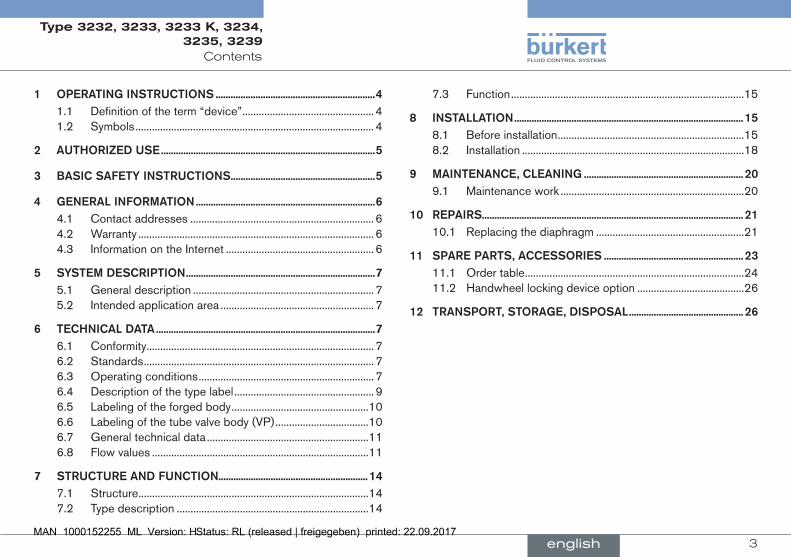
Contents
1 OperatinginstructiOns................................................................41.1 Definition of the term “device” ................................................ 41.2 Symbols ....................................................................................... 4
2 authOrizeduse......................................................................................5
3 BasicsafetyinstructiOns..........................................................5
4 generalinfOrmatiOn........................................................................64.1 Contact addresses ................................................................... 64.2 Warranty ...................................................................................... 64.3 Information on the Internet ...................................................... 6
5 systemdescriptiOn............................................................................75.1 General description .................................................................. 75.2 Intended application area ........................................................ 7
6 technicaldata........................................................................................76.1 Conformity ................................................................................... 76.2 Standards .................................................................................... 76.3 Operating conditions ................................................................ 76.4 Description of the type label ................................................... 96.5 Labeling of the forged body ..................................................106.6 Labeling of the tube valve body (VP) ..................................106.7 General technical data ...........................................................116.8 Flow values ...............................................................................11
7 structureandfunctiOn............................................................ 147.1 Structure ....................................................................................147.2 Type description ......................................................................14
7.3 Function .....................................................................................15
8 installatiOn............................................................................................158.1 Before installation ....................................................................158.2 Installation .................................................................................18
9 maintenance,cleaning................................................................ 209.1 Maintenance work ...................................................................20
10 repairs.........................................................................................................2110.1 Replacing the diaphragm ......................................................21
11 spareparts,accessOries........................................................ 2311.1 Order table ................................................................................2411.2 Handwheel locking device option .......................................26
12 transpOrt,stOrage,dispOsal.............................................. 26
english
Type 3232, 3233, 3233 K, 3234, 3235, 3239

4
Operating instructions
1 OperaTinginsTrucTiOnsThe operating instructions describe the entire life cycle of the device. Keep these instructions in a location which is easily accessible to every user and make these instructions available to every new owner of the device.
importantsafetyinformation.
Failure to observe these instructions may result in hazardous situations.
▶ The operating instructions must be read and understood.
1.1 Definitionoftheterm“device”
In these instructions, the term “device” always refers to the Type 3232, 3233, 3233 K, 3234, 3235 and 3239.
1.2 symbols
Danger!
Warnsofanimmediatedanger. ▶ Failure to observe the warning may result in a fatal or serious injury.
Warning!
Warnsofapotentiallydangeroussituation. ▶ Failure to observe the warning may result in serious injuries or death.
Caution!
Warnsofapossibledanger. ▶ Failure to observe this warning may result in a medium or minor injury.
note!
Warnsofdamagetoproperty.
Indicates important additional information, tips and recommendations.
Refers to information in these operating instructions or in other documentation.
▶ designates instructions for risk prevention.
→ designates a procedure which you must carry out.
english
Type 3232, 3233, 3233 K, 3234, 3235, 3239

5
Authorized use
2 auThOrizeDuse
non-authorizeduseofthedevicesmaybedangeroustopeople,nearbyequipmentandtheenvironment.
▶ The diaphragm valves of Types 3232, 3233, 3233 K, 3234, 3235 and 3239 are designed for the control of contaminated, ultra-pure or sterile media, as well as for abrasive or aggressive media (also with higher viscosity).
▶ In the potentially explosion-risk area the device may be used only according to the specification on the separate Ex type label. For use observe the additional information enclosed with the device together with safety instructions for the explosion-risk area.
▶ Devices without a separate Ex type label may not be used in a potentially explosive area.
▶ During use observe the authorized data, the operating conditions and conditions of use specified in the contract documents and operating instructions.
▶ The device may be used only in conjunction with third-party devices and components recommended and authorized by Bürkert.
▶ Correct transportation, correct storage and installation and care-ful use and maintenance are essential for reliable and faultless operation.
▶ Use the device only as intended.
3 BasicsafeTyinsTrucTiOns
These safety instructions do not make allowance for any
• Contingencies and events which may arise during the installation, operation and maintenance of the devices.
• Local safety regulations – the operator is responsible for observing these regulations, also with reference to the installation personnel.
danger–highpressure. ▶ Before loosening the lines and valves, turn off the pressure and vent the lines.
riskofelectricshock. ▶ Before reaching into the device or the equipment, switch off the power supply and secure to prevent reactivation!
▶ Observe applicable accident prevention and safety regulations for electrical equipment.
dangerofburstingfromoverpressure. ▶ Observe the specifications on the type label for maximum control and medium pressure.
▶ Observe permitted medium temperature.
riskofburnsorriskoffireifusedcontinuouslythroughhotdevicesurface.
▶ Keep the device away from highly flammable substances and media and do not touch with bare hands.
english
Type 3232, 3233, 3233 K, 3234, 3235, 3239
6
General information
generalhazardoussituations.
To prevent injury, ensure that: ▶ The system cannot be activated unintentionally. ▶ When closing the valve, tighten it hand-tight only. Overtightening may prematurely damage the diaphragm.
▶ Installation and repair work may be carried out by authorized technicians only and with the appropriate tools.
▶ After an interruption in the power supply or pneumatic supply, ensure that the process is restarted in a defined or controlled manner.
▶ The device may be operated only when in perfect condition and in consideration of the operating instructions.
▶ The general rules of technology apply to application planning and operation of the device.
To prevent damage to property of the device, ensure: ▶ The devices may be used only for media which do not attack the body and seal materials (see type label). Information on the resistance of materials to the media is available on the Internet at: www.burkert.com
▶ Do not put any loads on the body. ▶ Do not make any external modifications to the device body. Do not paint the body parts or screws.
4 generalinfOrmaTiOn
4.1 contactaddresses
germany
Bürkert Fluid Control Systems Sales Center Christian-Bürkert-Str. 13-17 D-74653 Ingelfingen Tel. + 49 (0) 7940 - 10 91 111 Fax + 49 (0) 7940 - 10 91 448 E-mail: [email protected]
international
Contact addresses can be found on the final pages of the printed operating instructions.
And also on the Internet at: www.burkert.com
4.2 Warranty
The warranty is only valid if the device is used as intended in accordance with the specified application conditions.
4.3 informationontheinternet
The operating instructions and data sheets for Types 3232, 3233, 3233 K, 3234, 3235, 3239 can be found on the Internet at: www.burkert.com
english
Type 3232, 3233, 3233 K, 3234, 3235, 3239

7
System description
5 sysTemDescripTiOn
5.1 generaldescription
Type 3232, 3233, 3233 K, 3234, 3235 and 3239 is a manually con-trolled diaphragm valve with diaphragm seal. The valve is self-draining in appropriate installation position.
5.2 intendedapplicationarea
The diaphragm valve of Type 3232 is designed for the control of con-taminated and aggressive media. The valves of Type 3233, 3233 K, 3234, 3235 and 3239 can be used even for ultra-pure or sterile media with a higher viscosity.
The valves may only control media which do not attack the body and seal materials (see type label). Information on the resistance of materials to the media is available from your Bürkert sales office.
6 TechnicalDaTa
6.1 conformity
Type 3232, 3233, 3233 K, 3234, 3235, 3239 conforms with the EU Directives according to the EU Declaration of Conformity.
6.2 standards
The applied standards, which verify conformity with the EU Directives, can be found on the EU-Type Examination Certificate and / or the EU Declaration of Conformity.
6.3 Operatingconditions
Warning!
dangerofburstingfromoverpressure.
If the device ruptures, the medium may cause injuries, chemical burns or scalds.
▶ Do not exceed the maximum medium pressure. Observe specifi-cations on the type label!
▶ Observe permitted ambient and media temperature.
english
Type 3232, 3233, 3233 K, 3234, 3235, 3239

8
Technical data
6.3.1 allowabletemperatures
ambienttemperatureforactuators:
material temperature
PPS Up to 130 °C (briefly up to 150 °C)
Stainless steel Up to 130 °C (briefly up to 150 °C)
Gray cast iron Up to 130 °C (briefly up to 150 °C)
Tab. 1: Ambient temperature for actuators
mediumtemperatureforbody:
Bodymaterial temperature
Stainless steel -10...+140 °C
PVC (see PT-Graph) -10...+60 °C
PVDF (see PT-Graph) -10...+120 °C
PP (see PT-Graph) -10...+80 °C
Tab. 2: Medium temperature for body
mediumtemperaturefordiaphragms:
material temperature remarks
EPDM (AB) -10...+130 °C Steam sterilisation up to +140 °C / 60 min
EPDM (AD) -5...+143 °C Steam sterilisation up to +150 °C / 60 min
FKM (FF) 0...+130 °C No steam / dry heat up to +150 °C / 60 min
PTFE (EA) -10...+130 °C Steam sterilisation up to +140 °C / 60 min
material temperature remarks
Advanced PTFE (EU)
-5...+143 °C Steam sterilisation up to +150 °C / 60 min
Advanced PTFE (ET)
-10...+90 °C -
Gylon (ER) -5...+130 °C Steam sterilisation up to +140 °C / 60 min
Tab. 3: Medium temperature for diaphragms
6.3.2 maximumpermittedmediumpressure
Permitted medium pressure depending on the medium temperature:
DN 15 - 6510
8
6
4
2
20 40 60 80 100 120 140
PVC
PVDF
PP
Temperature [°C]
Med
ium
pre
ssur
e [b
ar]
Fig. 1: Graph of medium pressure / Medium temperature
english
Type 3232, 3233, 3233 K, 3234, 3235, 3239
9
Technical data
maximumpermittedmediumpressure
The values apply to body made of:
• plastic,
• stainless steel: block material, forged, casted and tube valve body.
Orifice(diaphragm
size)dn
[mm]
max.switchablemediumpressure[bar]
handwheelandbonnetpps
handwheelpps/Bonnetstainlesssteel
epdm/fKm ptfe/advanced
ptfe/laminatedadvanced
ptfe
epdm/fKm ptfe/advanced
ptfe/laminatedadvanced
ptfe
8 10 10 10 10
15 10 10 10 10
20 10 10 10 10
25 10 10 10 10
32 10 10 10 10
40 10 10 10 10
50 7 7 10 10
Tab. 4: Maximum permitted medium pressure
maximumpermittedmediumpressure
Orifice(diaphragm
size)dn
[mm]
max.switchablemediumpressure[bar]
handwheelandbonnetstainlesssteel
epdm/fKm ptfe/advancedptfe/laminatedadvanced
ptfe
65 10 10
80 10 10
100 6 6
Tab. 5: Maximum permitted medium pressure
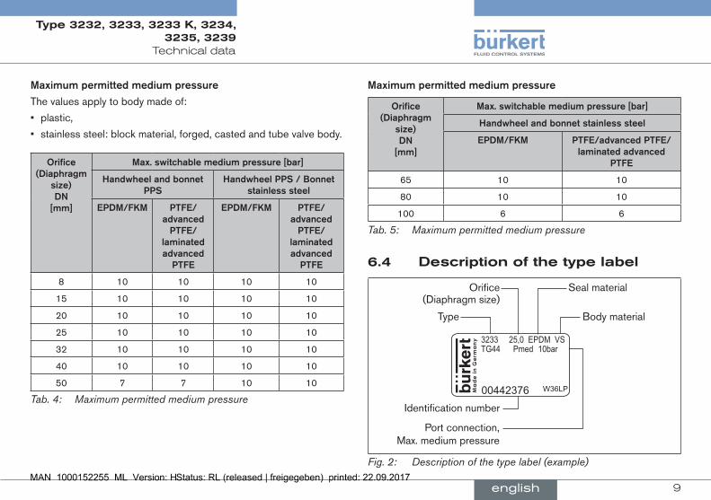
6.4 Descriptionofthetypelabel
3233 25,0 EPDM VS
Ma
de
in G
erm
any
00442376 W36LP
TG44 Pmed 10bar
Type
Orifice (Diaphragm size)
Body material
Identification number
Seal material
Port connection, Max. medium pressure
Fig. 2: Description of the type label (example)
english
Type 3232, 3233, 3233 K, 3234, 3235, 3239

10
Technical data
6.5 labelingoftheforgedbody
XXXXXXXXXX
XX F
1.4435/316L(VS)PN16/CWP150
XXXXXXXX/XXX
XXXXXXXXXX
Batch number/ manufacturing code
Company logo
Material
Nominal pressure
Production/order number (F-part)
Serial number
Self-drain angle
Customized text (optional)
Connection orifice and tube sizes
Fig. 3: Labeling of the forged body
6.6 labelingofthetubevalvebody(Vp)
1.4435316L(VP) XXXXXXXX
XXXXXXXXXX
PN16 / CWP150
XXXXXXXX / XXXXXXX / XXXXXX
Material HeatCompany logo
Nominal pressure
Connection orifice and pipe dimensions
Self-drain angle / Customer-specific text
(optional)
Production number order number / Serial number
Fig. 4: Labeling of the tube valve body (VP)
english
Type 3232, 3233, 3233 K, 3234, 3235, 3239

11
Technical data
6.7 generaltechnicaldata
materials
Body Tube valve body (VA, VP), Precision casting (VG), Forged steel (VS), PP, PVC, PVDF
Actuator Handwheel and bonnet PPS Handwheel PPS and bonnet stainless steel Handwheel and bonnet stainless steel DN65 to DN100
Diaphragm EPDM, PTFE, FKM
connections
Medium connection Welded connection according to DIN EN 1127 (ISO 4200), DIN 11850 series 2, DIN 11866 (ASME-BPE 2005) other connections on request
media
Flow media Type 3232; contaminated, aggressive, ultrapure, sterile media and media with higher viscosity
installationposition In any position, floor drain valve type 3235;
actuator face down
6.8 flowvalues
6.8.1 flowvaluesforforgedbodies
Kvsvalues[m3/h] forforgedbodies
diaph-ragmsize
Orificeconnec-tion(dn)
actua-torsize
sealmate-rial
din isO asme Bs sms
8 6 C/40 EPDM 1.1
PTFE 1.1
8 / 1/4" C/40 EPDM 1.7 1.5 0.7 0.5
PTFE 1.9 2.0 0.7 0.5
10 / 3/8" C/40 EPDM 1.5 1.5 1.6 1.4
PTFE 1.9 2.0 1.8 1.6
15 / 1/2" C/40 EPDM 1.5
PTFE 1.9
15 10 / 3/8" E/63 EPDM 3.5 5.5
PTFE 3.4 5.2
15 / 1/2" E/63 EPDM 6.5 6.5 3.1 3.7
PTFE 6.0 6.0 3.1 3.6
20 / 3/4" E/63 EPDM 6.5
PTFE 6.0
20 20 / 3/4" F/80 EPDM 12.4 12.5 8.4 8.9
PTFE 12.0 12.0 8.5 8.8
english
Type 3232, 3233, 3233 K, 3234, 3235, 3239

12
Technical data
25 25 / 1" F/80 EPDM 20.0 18.0 15.5 16.0
PTFE 17.0 16.0 14.5 14.8
40 32 H/125 EPDM 34.0
PTFE 34.0
40 / 1 1/2"
H/125 EPDM 40.0 41.0 37.0 38.0
PTFE 40.0 40.0 37.5 38.0
50 50 / 2" H/125 EPDM 66.0 66.0 66.0 66.0
PTFE 66.0 67.0 66.0 66.0
2 1/2" H/125 EPDM 66.0
PTFE 66.0
Tab. 6: Kvs values for forged bodies
6.8.2 flowvaluesforcastbodiesandplasticbodies
Kvsvalue[m3/h] forcastbodiesVgandplasticbodiespd.pp.pV
diaphragmsize
Orificeconnection(dn)
sealmaterial
castbodyVg(allstandards)
plasticbody(allmaterials)*
8 8 EPDM 0.95 -
PTFE 1.5 -
15 15 EPDM 5.6 3
PTFE 5.3 3
20 20 EPDM 10.7 7
PTFE 10.5 6.7
25 25 EPDM 14.6 11.4
PTFE 13.6 10
32 32 EPDM - 17.5
PTFE - 17.1
40 40 EPDM 35.0 24.5
PTFE 35.0 24.0
50 50 EPDM 47.0 41.5
PTFE 48.0 41.5
Tab. 7: Kvs values for cast bodies and plastic bodies
* Plastic bodies: measured with bodies ASV
english
Type 3232, 3233, 3233 K, 3234, 3235, 3239

13
Technical data
6.8.3 flowvaluesfortubevalvebody
Kvsvalues[m3/h] fortubevalvebodyVp(ihu2)tVB3g
diaphragmsize
Orificeconnection(dn)
actuatorsize
sealmaterial
din isO asme
8 8 / 1/4" C/40 EPDM 1.9
PTFE 2.4
10 / 3/8" C/40 EPDM 1.9
PTFE 2.4
15 / 1/2" C/40 EPDM
PTFE 2.2
15 15 / 1/2" E/63 EPDM 7.2 7
PTFE 6.7 6.6
20 / 3/4" E/63 EPDM 6.9
PTFE 5.5 6.5
20 20 / 3/4" F/80 EPDM 13.5
PTFE 12.1
25 / 1" F/80 EPDM 14.9
PTFE 13.7 12.7
25 25 / 1" E/63 EPDM 17.3
PTFE 14.1
32 E/63 EPDM 18.6
PTFE 14.2
25 / 1" F/80 EPDM 19.1
PTFE 15.6
32 F/80 EPDM 20.0
PTFE 15.8
32 32 G/100 EPDM 36.0
PTFE 36.0
40 / 1 1/2" G/100 EPDM 35.0
PTFE 34.5 32.0
40 40 / 1 1/2" H/125 EPDM 48.0
PTFE 47.0
50 / 2" H/125 EPDM 46.0
PTFE 43.5 45.0
50 50 / 2" H/125 EPDM 70.0
PTFE 70.0
Tab. 8: Kvs values for tube valve body VP
english
Type 3232, 3233, 3233 K, 3234, 3235, 3239

14
Structure and Function
7 sTrucTureanDfuncTiOn
7.1 structure
The manually actuated diaphragm valve consists of a manual actuator and a 2/2-way valve body.
7.2 Typedescription
The types differ in the body.
7.2.1 Type3232,3233and3233K
Handwheel with position indicator (see chapter “7.3.1”)
Attachment
Diaphragm body
Port connection
Fig. 5: Example of the 2/2-way valve type 3232, 3233 and 3233 K
7.2.2 Types3234,3235and3239
type Body structure
T-Valve Type 3234
T-Valve body
Tank bottom valve
Type 3235
Tank bottom valve with welding flange
Y-Valve Type 3239
Y-Valve body
Tab. 9: Structure. Types 3234, 3235 and 3239
english
Type 3232, 3233, 3233 K, 3234, 3235, 3239

15
Installation
7.3 function
The manual actuation of the handwheel transfers the force via a spindle and opens and closes the valve.
7.3.1 positionindicator
actuatorsizedn4,dn6,dn8anddn10
When the valve is opened, a yellow mark is visible between the bonnet and the handwheel.
actuatorsizedn15todn50
From DN15 a yellow cylinder provides information on the valve position:
• Yellow cylinder completely retracted in the handwheel: Valveclosed(CLOSED position)
• Yellow cylinder projects all the way out of the handwheel: Valveopened(OPEN position)
actuatorsizedn65,dn80anddn100
From DN65 an spindle extension indicates the valve position:
• Spindle extension completely retracted in the handwheel: Valveclosed (CLOSED position)
• Spindle extension projects all the way out of the handwheel: Valveopened (OPEN position)
8 insTallaTiOn
Danger!
riskofinjuryfromhighpressureintheequipment. ▶ Before loosening the lines and valves, turn off the pressure and vent the lines.
riskofinjuryduetoelectricalshock. ▶ Before reaching into the device or the equipment, switch off the power supply and secure to prevent reactivation.
▶ Observe applicable accident prevention and safety regulations for electrical equipment.
Warning!
riskofinjuryfromimproperinstallation. ▶ Installation may be carried out by authorized technicians only and with the appropriate tools.
riskofinjuryfromunintentionalactivationofthesystemandanuncontrolledrestart.
▶ Secure system from unintentional activation. ▶ Following assembly, ensure a controlled restart.
8.1 Beforeinstallation
• Before connecting the valve, ensure the pipelines are flush.
• The flow direction is optional.
english
Type 3232, 3233, 3233 K, 3234, 3235, 3239

16
Installation
8.1.1 installationpositiongeneral
installationforself-drainageofthebody
It is the responsibility of the installer and operator to ensure self-drainage.
installationforleakagedetection
One of the bores in the diaphragm socket for monitoring leakage must be at the lowest point.
8.1.2 installationposition2/2-wayvalve
• The manually actuated diaphragm valve can be installed in any position.
To ensure self-drainage:
→ Install body inclined by angle α = 10° to 40° to the horizontal (see “Fig. 6”). Forged and cast body feature a mark which must face upwards (12 o’clock position, see “Fig. 7”).
→ Observe an inclination angle of 1° – 5°.
→ One of the bores in the diaphragm socket for monitoring leakage must be at the lowest point.
αAngle α: 10° to 40°
Inclination to the line axis 1° – 5°
Fig. 6: Installation position for self-drainage of the body
Mark for self-drainage angle
Fig. 7: Mark for the correct installation position
english
Type 3232, 3233, 3233 K, 3234, 3235, 3239
17
Installation
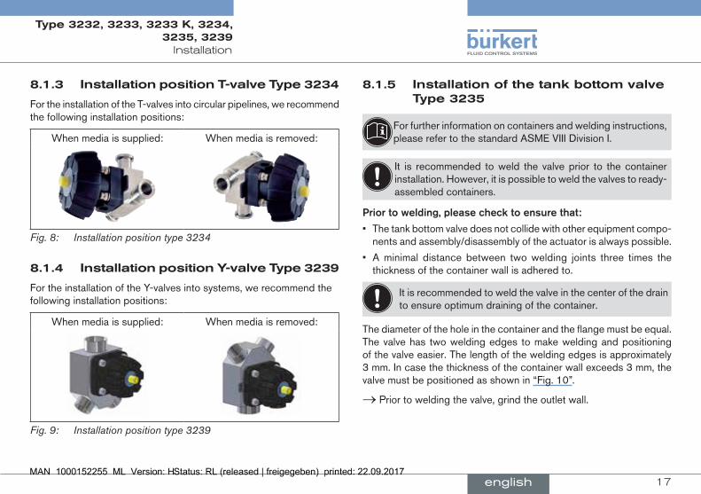
8.1.3 installationpositionT-valveType3234
For the installation of the T-valves into circular pipelines, we recommend the following installation positions:
When media is supplied: When media is removed:
Fig. 8: Installation position type 3234
8.1.4 installationpositiony-valveType3239
For the installation of the Y-valves into systems, we recommend the following installation positions:
When media is supplied: When media is removed:
Fig. 9: Installation position type 3239
8.1.5 installationofthetankbottomvalveType3235
For further information on containers and welding instructions, please refer to the standard ASME VIII Division I.
It is recommended to weld the valve prior to the container installation. However, it is possible to weld the valves to ready-assembled containers.
priortowelding,pleasechecktoensurethat:
• The tank bottom valve does not collide with other equipment compo-nents and assembly/disassembly of the actuator is always possible.
• A minimal distance between two welding joints three times the thickness of the container wall is adhered to.
It is recommended to weld the valve in the center of the drain to ensure optimum draining of the container.
The diameter of the hole in the container and the flange must be equal. The valve has two welding edges to make welding and positioning of the valve easier. The length of the welding edges is approximately 3 mm. In case the thickness of the container wall exceeds 3 mm, the valve must be positioned as shown in “Fig. 10”.
→ Prior to welding the valve, grind the outlet wall.
english
Type 3232, 3233, 3233 K, 3234, 3235, 3239

18
Installation
Grinding point on tank
Fig. 10: Grinding point on tank
Prior to commencing the welding process, check the charge number indicated on the supplied manufacturer‘s certificate 3.1.
→ Position the flange into the hole so that the flange surface is tangent to the drain surface. → Tack 4 welding points and check the position of the valve. → Weld the valve evenly to the inside and outside of the container, with gas being supplied and using welding material compatible with the valve‘s stainless steel 316 L (DIN 1.4435). → Allow the welds to cool down before burnishing and cleaning them according to the applicable specifications.
These instructions assist in the installation of the tank bottom valves and allow the prevention of deformation and softening within the containers.
Please observe the applicable laws and regulations of the respective country with regard to the qualification of welders and the execution of welding work.
8.1.6 preparatorywork
→ Clean pipelines (sealing material, swarf, etc.).
→ Support and align pipelines.
deviceswithweldedorgluedbody:
Before welding or gluing the body, the actuator and the diaphragm must be removed.
8.2 installation
Warning!
riskofinjuryfromimproperinstallation!
Non-observance of the tightening torque is dangerous as the device may be damaged.
▶ Observe tightening torque during installation (see “8.2.2 Tight-ening torques for diaphragms”).
8.2.1 Deviceswithweldedorgluedbody
note!
topreventdamage.
Before welding or gluing the body, the actuator and the diaphragm must be removed.
english
Type 3232, 3233, 3233 K, 3234, 3235, 3239

19
Installation
→ Cross-loosen fastening screws and remove actuator with dia-phragm from the body.
→ Weld or glue body in the pipeline.
→ After welding or gluing in the body, smooth the body surface (if required) by grinding.
→ Clean the body carefully.
→ Place actuator on the body.
→ Lightly cross-tighten the fastening screws until the diaphragm is between the body and actuator. Do not tighten screws yet.
→ Activate the diaphragm valve twice to position the diaphragm correctly.
→ Tighten the fastening screws up to the permitted tightening torque (see tables in chapter “8.2.2 Tightening torques for diaphragms”).
8.2.2 Tighteningtorquesfordiaphragms
Orifice(diaphragmsize)
dn[mm]
actuatorppsorstainlesssteel
diaphragmepdm/fKm
diaphragmptfe/advancedptfe/laminatedadvancedptfe
8 2 2,5
15 3,5 4
20 4 4,5
25 5 6
32 6 8
40 8 10
50 12 15
Tab. 10: Tightening torques for diaphragms. Actuator PPS or stainless steel
Orifice(diaphragmsize)
dn[mm]
actuatorstainlesssteel
diaphragmepdm/fKm
diaphragmptfe/advancedptfe/laminatedadvancedptfe
65 20 30
80 30 40
100 40 50
Tab. 11: Tightening torques for diaphragms. Actuator stainless steel
english
Type 3232, 3233, 3233 K, 3234, 3235, 3239

20
Maintenance, Cleaning
9 mainTenance,cleaning
Danger!
riskofinjuryduetoelectricalshock. ▶ Before reaching into the system , switch off the power supply and secure to prevent reactivation.
▶ Observe applicable accident prevention and safety regulations for electrical equipment.
Warning!
riskofinjuryfromimpropermaintenance. ▶ Installation may be carried out by authorized technicians only and with the appropriate tools.
riskofinjuryfromunintentionalactivationofthesystemandanuncontrolledrestart.
▶ Secure system from unintentional activation. ▶ Following maintenance, ensure a controlled restart.
9.1 maintenancework
The following maintenance work is required for the diaphragm valve:
→ After the first steam sterilization or when required retighten body screws crosswise.
9.1.1 WearingpartsofthediaphragmvalveParts which are subject to natural wear:
• Seals
• Diaphragm
→ If leaks occur, replace the particular wearing parts with an appro-priate spare part (see chapter “11”).
A bulging PTFE diaphragm may reduce the flow-rate.
9.1.2 servicelifeofthediaphragm
The service life of the diaphragm depends on the following factors:
• Diaphragm material,
• Medium,
• Medium pressure,
• Medium temperature.
9.1.3 actuator
The actuator of the diaphragm valve is maintenance-free provided it is used according to these operating instructions.
9.1.4 cleaning
Commercially available cleaning agents can be used to clean the outside.
note!
avoidcausingdamagewithcleaningagents. ▶ Before cleaning, check that the cleaning agents are compatible with the body materials and seals.
english
Type 3232, 3233, 3233 K, 3234, 3235, 3239
21
Repairs
10 repairs
Danger!
riskofinjuryfromhighpressureintheequipment. ▶ Before loosening the lines and valves, turn off the pressure and vent the lines.
riskofinjuryduetoelectricalshock. ▶ Before reaching into the system , switch off the power supply and secure to prevent reactivation.
▶ Observe applicable accident prevention and safety regulations for electrical equipment.
Warning!
riskofinjuryfromimpropermaintenance. ▶ Repairs may be carried out by authorized technicians only and with the appropriate tools.
▶ Observe the tightening torques. ▶ On completion of the work check valve for leaks and function.
riskofinjuryfromunintentionalactivationofthesystemandanuncontrolledrestart.
▶ Secure system from unintentional activation. ▶ Following maintenance, ensure a controlled restart.
10.1 replacingthediaphragm
Danger!
riskofinjuryfromdischargeofmedium(acid,alkali,hotmedia).
It is dangerous to remove the device under pressure due to the sudden release of pressure or discharge of medium.
▶ Before removing a device, switch off the pressure and vent the lines. ▶ Completely drain the lines.
fasteningtypes
Orifice(diaphragmsize)
dn[mm]
fasteningtypesfordiaphragm
ptfe epdm/fKm
8 Diaphragm buttoned Diaphragm buttoned
15 Diaphragm with bayonet catch
Diaphragm with bayonet catch20
25
Diaphragm with bayonet catch
Diaphragm screwed in40
50
65
80 Diaphragm with bayonet catch
Diaphragm screwed in100
Tab. 12: Fastening types for diaphragm
english
Type 3232, 3233, 3233 K, 3234, 3235, 3239

22
Repairs
Diaphragm
4 fastening screws
Manual actuator
4 fastening screws
BodyMark tab for direction of flow
Fig. 11: Replacing the diaphragm
→ Clamp valve body in a holding device (applies only to valves not yet installed).
→ Cross-loosen fastening screws and remove actuator with dia-phragm from the body.
→ Detach or unscrew old diaphragm. If bonnet is with a bayonet catch, loosen the diaphragm by turning it 90°. For orifice DN25-DN50 observe chapter “10.1.1”.
→ Turn handwheel all the way clockwise (CLOSED position).
→ Install new diaphragm in the actuator (see “Tab. 12”).
→ Turn handwheel all the way counter-clockwise (OPEN position).
→ Align diaphragm. notemarkerfordirectionofflow!
→ Place actuator back on the body.
→ Lightly cross-tighten the fastening screws until the diaphragm is between the body and actuator. donottightenscrewsyet.
→ Activate the diaphragm valve once to position the diaphragm correctly.
→ Tighten the fastening screws with the valve in the open position up to the permitted tightening torque (see tables in chapter “10.1.2 Tightening torques for diaphragms”).
→ Check the tightening torque of the screws again.
10.1.1 switchbetweenpTfeandepDmdiaphragms
Orificedn8:
→ Detach PTFE diaphragm and attach new EPDM diaphragm.
Orificedn15anddn20:
→ Loosen PTFE diaphragm bayonet and attach new EPDM diaphragm.
Orificedn25uptodn50:
→ Loosen PTFE diaphragm bayonet.
→ Place the insert in the pressure piece.
→ Insert and screw in EPDM diaphragm.
english
Type 3232, 3233, 3233 K, 3234, 3235, 3239
23
Spare parts, Accessories
10.1.2 Tighteningtorquesfordiaphragms
Orifice(diaphragmsize)
dn[mm]
actuatorppsorstainlesssteel
diaphragmepdm/fKm
diaphragmptfe/advancedptfe/laminatedadvancedptfe
8 2 2,5
15 3.5 4
20 4 4.5
25 5 6
32 6 8
40 8 10
50 12 15
Tab. 13: Tightening torques for diaphragms, actuator PPS or stainless steel
Orifice(diaphragmsize)
dn[mm]
actuatorstainlesssteel
diaphragmepdm/fKm
diaphragmptfe/advancedptfe/laminatedadvancedptfe
65 20 30
80 30 40
100 40 50
Tab. 14: Tightening torques for diaphragms, actuator stainless steel
11 spareparTs,accessOries
Caution!
riskofinjuryand/ordamagebytheuseofincorrectparts.
Incorrect accessories and unsuitable spare parts may cause injuries and damage the device and the surrounding area.
▶ Use only original accessories and original spare parts from Bürkert.
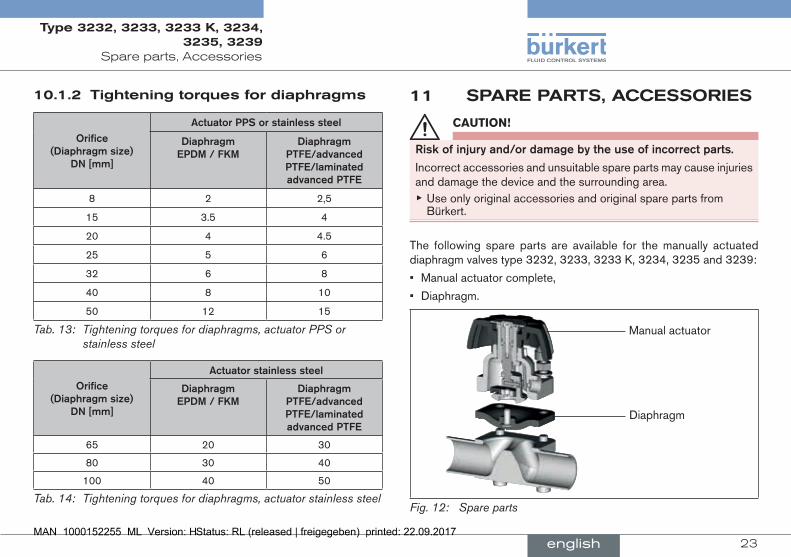
The following spare parts are available for the manually actuated diaphragm valves type 3232, 3233, 3233 K, 3234, 3235 and 3239:
• Manual actuator complete,
• Diaphragm.
Manual actuator
Diaphragm
Fig. 12: Spare parts
english
Type 3232, 3233, 3233 K, 3234, 3235, 3239

24
Spare parts, Accessories
11.1 Ordertable
11.1.1 Ordertablesformanualactuators(types3232,3233and3233K)
Orifice(diaphragm
size)[mm]
handwheelandbonnetpps
handwheelpps,bonnetstainlesssteel
diaphragmepdm,fKm
diaphragmptfe/
advancedptfe/
laminatedadvanced
ptfe
diaphragmepdm,fKm
diaphragmptfe/
advancedptfe/
laminatedadvanced
ptfe
8 194 809 194 809 271 974 271 974
15 432 9781) 432 978 432 9801) 432 980
20 432 9851) 432 985 432 9871) 432 987
25 432 991 432 992 432 993 432 994
32 432 998 432 999 433 000 433 001
40 433 005 433 006 433 007 433 008
50 433 012 433 013 433 014 433 015
Tab. 15: Order table for manual actuator
1) Use diaphragm with bayonet connection (BC) (see “Tab. 17”).
Manual actuators for orifice DN65, DN80 and DN100 on request.
Orifice(diaphragm
size)[mm]
handwheelandbonnetstainlesssteel
handwheelandbonnetstainlesssteel(fortor
tankbottomvalve)
diaphragmepdm,fKm
diaphragmptfe/
advancedptfe/
laminatedadvanced
ptfe
diaphragmepdm,fKm
diaphragmptfe/
advancedptfe/
laminatedadvanced
ptfe
8 271 975 271 975 271 977 271 977
15 432 9811) 432 981 441 2701) 441 270
20 432 9881) 432 988 449 1281) 449 128
25 427 755 432 995 441 267 441 271
32 427 756 433 002 - -
40 427 757 433 009 441 268 441 276
50 427 758 433 016 441 269 441 277
Tab. 16: Order table for manual actuators1) Use diaphragm with bayonet connection (BC) (see “Tab. 17”).
english
Type 3232, 3233, 3233 K, 3234, 3235, 3239
25
Spare parts, Accessories
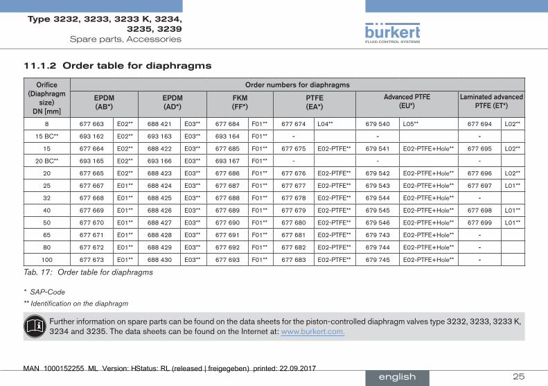
11.1.2 Ordertablefordiaphragms
Orifice(diaphragm
size)dn[mm]
Ordernumbersfordiaphragms
epdm(aB*)
epdm(ad*)
fKm(ff*)
ptfe(ea*)
advancedptfe(eu*)
laminatedadvancedptfe(et*)
8 677 663 E02** 688 421 E03** 677 684 F01** 677 674 L04** 679 540 L05** 677 694 L02**
15 BC** 693 162 E02** 693 163 E03** 693 164 F01** - - -
15 677 664 E02** 688 422 E03** 677 685 F01** 677 675 E02-PTFE** 679 541 E02-PTFE+Hole** 677 695 L02**
20 BC** 693 165 E02** 693 166 E03** 693 167 F01** - - -
20 677 665 E02** 688 423 E03** 677 686 F01** 677 676 E02-PTFE** 679 542 E02-PTFE+Hole** 677 696 L02**
25 677 667 E01** 688 424 E03** 677 687 F01** 677 677 E02-PTFE** 679 543 E02-PTFE+Hole** 677 697 L01**
32 677 668 E01** 688 425 E03** 677 688 F01** 677 678 E02-PTFE** 679 544 E02-PTFE+Hole** -
40 677 669 E01** 688 426 E03** 677 689 F01** 677 679 E02-PTFE** 679 545 E02-PTFE+Hole** 677 698 L01**
50 677 670 E01** 688 427 E03** 677 690 F01** 677 680 E02-PTFE** 679 546 E02-PTFE+Hole** 677 699 L01**
65 677 671 E01** 688 428 E03** 677 691 F01** 677 681 E02-PTFE** 679 743 E02-PTFE+Hole** -
80 677 672 E01** 688 429 E03** 677 692 F01** 677 682 E02-PTFE** 679 744 E02-PTFE+Hole** -
100 677 673 E01** 688 430 E03** 677 693 F01** 677 683 E02-PTFE** 679 745 E02-PTFE+Hole** -
Tab. 17: Order table for diaphragms
* SAP-Code
** Identification on the diaphragm
Further information on spare parts can be found on the data sheets for the piston-controlled diaphragm valves type 3232, 3233, 3233 K, 3234 and 3235. The data sheets can be found on the Internet at: www.burkert.com.
english
Type 3232, 3233, 3233 K, 3234, 3235, 3239
26
Transport, Storage, Disposal
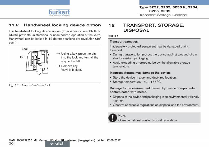
11.2 handwheellockingdeviceoption
The handwheel locking device option (from actuator size DN15 to DN50) prevents unintentional or unauthorized operation of the valve. Handwheel can be locked in 12 detent positions per revolution (30° each).
Lock
Pin → Using a key, press the pin into the lock and turn all the way to the left.
→ Remove key. Valve is locked.
Fig. 13: Handwheel with lock
12 TranspOrT,sTOrage,DispOsal
note!
transportdamages.
Inadequately protected equipment may be damaged during transport.• During transportation protect the device against wet and dirt in
shock-resistant packaging. • Avoid exceeding or dropping below the allowable storage
temperature.
incorrectstoragemaydamagethedevice.
• Store the device in a dry and dust-free location.• Storage temperature: -40…+55 °C.
damagetotheenvironmentcausedbydevicecomponentscontaminatedwithmedia.
• Dispose of the device and packaging in an environmentally friendly manner.
• Observe applicable regulations on disposal and the environment.
note:
Observe national waste disposal regulations.
english
Type 3232, 3233, 3233 K, 3234, 3235, 3239


www.burkert.com
Recommended