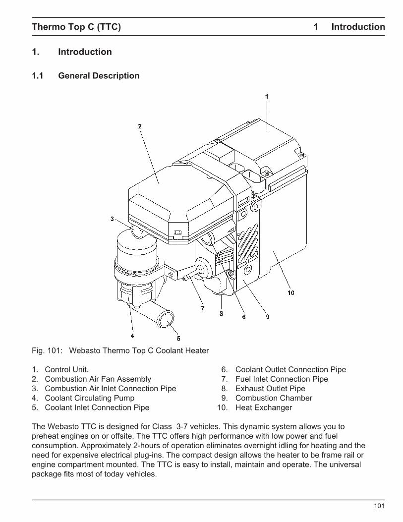
Coolant Heater
Thermo Top (TTC)
Operating Instructions Installation Instructions

hermo Top C (TTC)
-
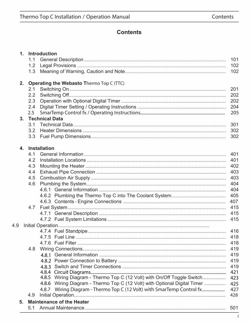
Thermo Top C Installation / Operation Manual Contents
2.5 SmarTemp Control fx / Operating Instructions............................................................................. 205
4.8.7 Wiring Diagram - Thermo Top C (12 Volt) with SmarTemp Control fx..................... 427428
4.8.14.8.24.8.34.8.4 Circuit Diagrams........................................................................................................................... 421 4.8.5 4.8.6
423425
& Comfort N.A.,
& Comfort N.A.,
& comfort N.A.,
Instant Heat Heat
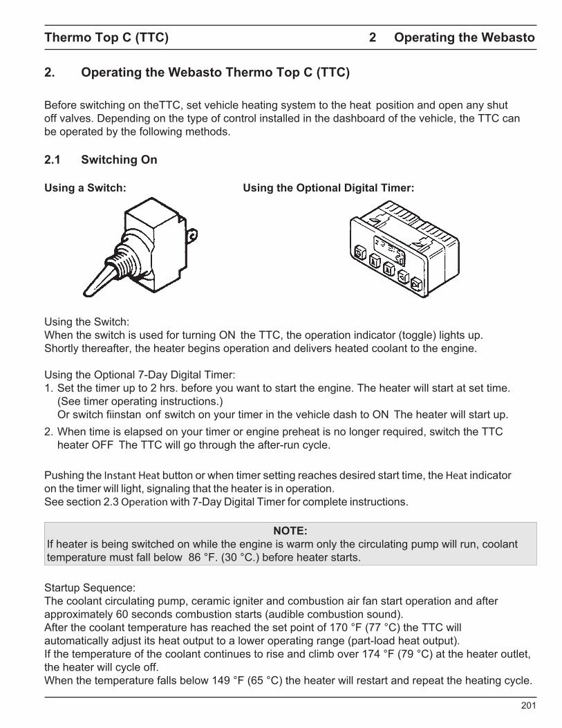
Operation
Instant Heat
Instant Heat
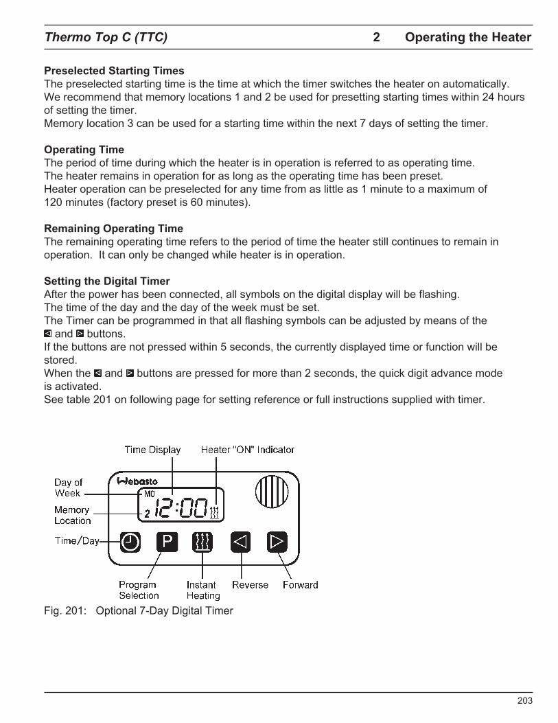
Thermo Top C (TTC) 2 Operating the Heater
2.5 Operation with Optional SmarTemp Control fx
Preselected Starting Times The preselected starting time is the time at which the timer switches the heater on automatically. The Webasto SmarTemp Control fx allows for preset start-up cycles of your Webasto heater up to 7 days in advance with 4 unique programs for each day.
Operating Time The period of time during which the heater is in operation is referred to as operating time. The heater remains in operation for as long as the operating time has been preset. Heater operation can be preselected for any time from as little as 10 minutes to a maximum of 120 minutes (factory preset is 60 minutes).
Remaining Operating Time The remaining operating time refers to the period of time the heater still continues to remain in operation. This can be changed with duration menu feature explain further in menu descriptions on page 206.
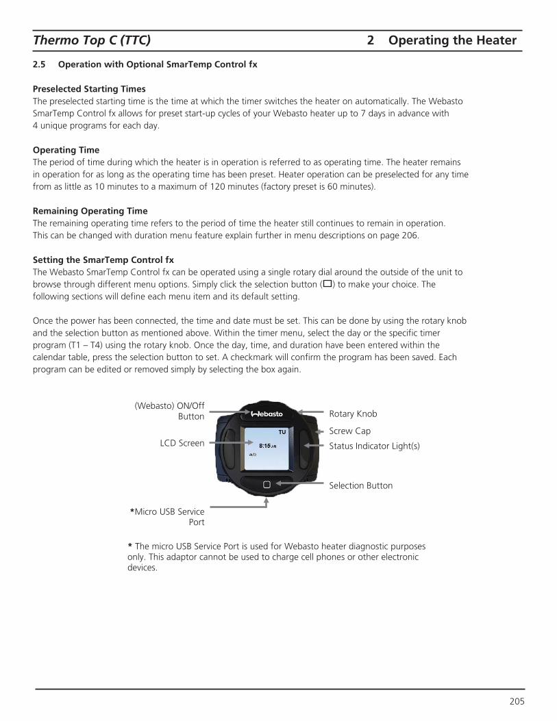
Setting the SmarTemp Control fx The Webasto SmarTemp Control fx can be operated using a single rotary dial around the outside of the unit to browse through different menu options. Simply click the selection button ( ) to make your choice. The following sections will define each menu item and its default setting.
Once the power has been connected, the time and date must be set. This can be done by using the rotary knob and the selection button as mentioned above. Within the timer menu, select the day or the specific timer program (T1 – T4) using the rotary knob. Once the day, time, and duration have been entered within the calendar table, press the selection button to set. A checkmark will confirm the program has been saved. Each program can be edited or removed simply by selecting the box again.
(Webasto) ON/Off Button Rotary Knob
LCD Screen Screw Cap
Status Indicator Light(s)
Selection Button
*Micro USB ServicePort
* The micro USB Service Port is used for Webasto heater diagnostic purposesonly. This adaptor cannot be used to charge cell phones or other electronic devices.
205
2 Operating the Heater Thermo Top (TTC)
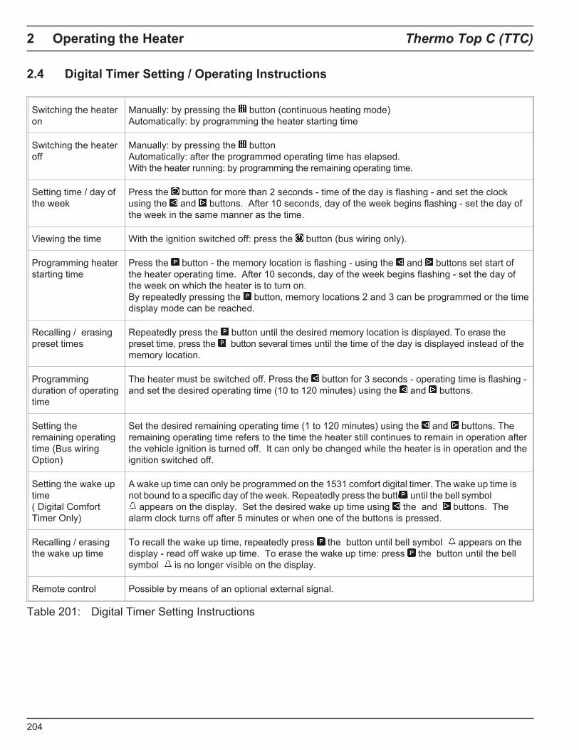
2.6 SmarTemp Control fx / Operating instructions
Definitions Default
Time & Date Time & Date allows user to properly set the current date and time. User also has the ability to switch between AM/PM and 24 hour modes.
AM / PM
(12 Hour)
Mode Two modes are possible:
– Auto mode will allow the heater to turn ON/OFF based on the pre-defined timer programs.Manual ON/OFF operation is still possible while in this mode.
– Manual Mode allows the heater to be manually operated via the Webasto button on theSmarTemp Control fx. While in Manual Mode, all Auto Mode functionality is disabled (Timersinactive).
Note: While in manual mode the heater will continue to operate based on the pre-defined “Duration” set by the user. See “Duration” for further detail.
Manual
Duration Duration allows for the selection of timed heater run-time. Set range is between 10 – 120 minutes selectable by 10 minute increments.
While using Manual Mode, the “Duration” setting will be used for the run-time of the heater when the Webasto button is pressed.
60 minutes
Timer Timer allows the user to set 4 heater start-up cycles per day up to 7 days in advance. Select the day or the specific timer program (T1 – T4) using the rotary knob and the selection button. Once the day, time, and duration have been entered, press the selection button to set. A checkmark will confirm the program has been saved. Each program can be edited or removed simply by selecting the box again.
Note: Setting the Duration run-time (in the Duration section) before setting a timer program will default all new programs to the user defined duration time.
No Presets
Skip The Skip feature looks similar to timer programming; however when a specific timer program is selected, it will update the checkmark to an “s” for skipped. When a program has been skipped, it will disable that specific timer program for one cycle (7 day period). Preset timer programming will reactivate after this one-time skip cycle.
Note: To permanently remove a program, refer to the “Timer” section.
N/A
LVD LVD “Low Voltage Disconnect” allows the user to adjust the battery voltage level at which the Webasto SmarTemp Control fx will shut down heater functionality.
If battery voltage is equal to or less than the threshold selected +0.1v, the heater will not start. i.e. if an 11.5v threshold is selected the heater cannot be started until B+ has reached 11.7v.
12 volt - Range between 11v – 12.5v
24 volt - Range between 21v – 25.5v 12.1v
24.2v
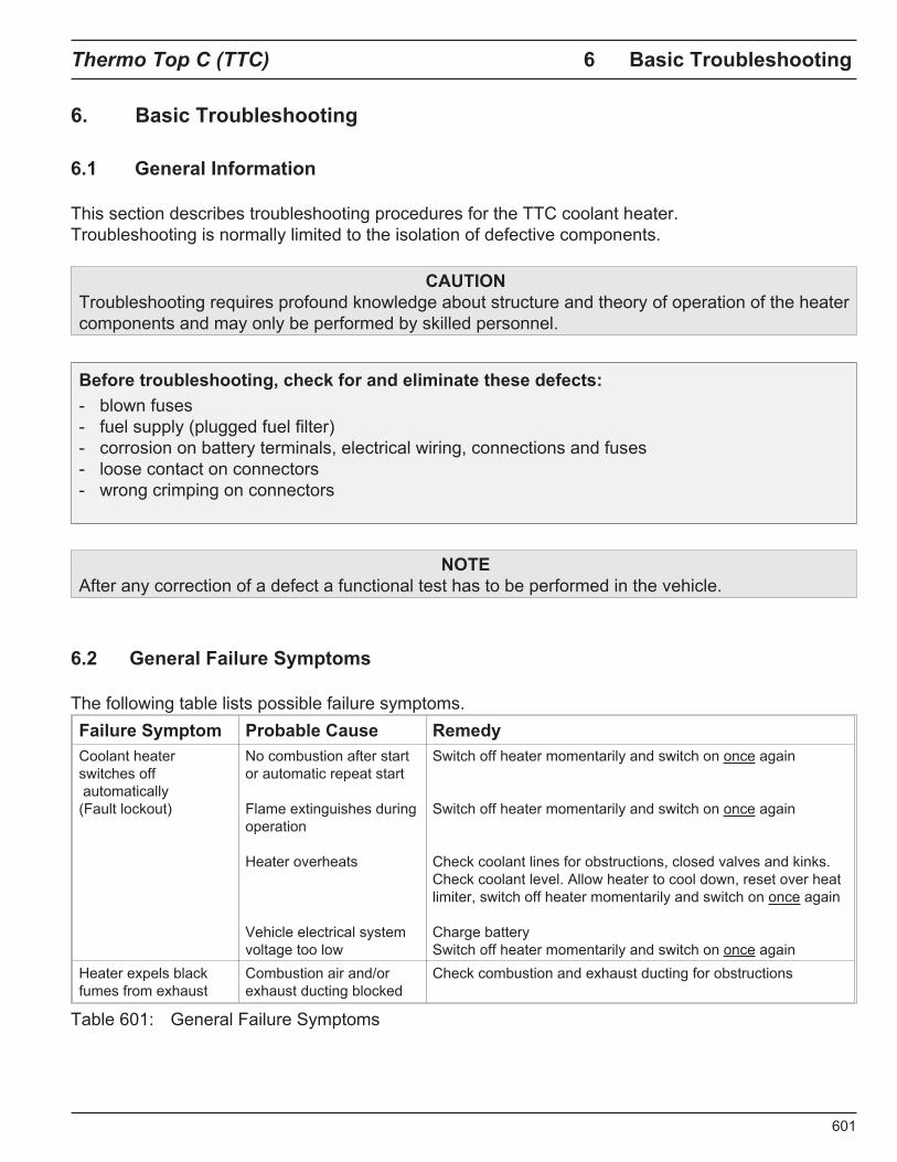
Error Codes This section will log the last 5 error codes and the date that it was set. Highlight and select an error code for a full description.
If the heater produces an error code, the status indicator lights will flash red and the error will display on the main screen. Error codes cannot be reset through the Webasto SmarTemp Control fx. Refer to the heater service manual for resetting an error code.
Note: Error code functionality does not apply to Thermo Top C heaters. Errors codes for this product can still be obtained using PC Diagnostics. Refer to the applicable service manual by visiting www.techwebasto.com for detailed PC diagnostics information.
No Errors
Hour Meter The hour meter logs the operating hours that the heater is commanded “ON” from the SmarTemp Control fx.
Note: For warranty purposes a diagnostic printout is still required where applicable. This hour meter is for reference only!
N/A
Default Default allows the user to perform a factory reset of the control settings and saved timer program data.
N/A
SW Version This displays the firmware version of the Webasto SmarTemp Control fx. Installed Version
Back Select this to return to the previous screen. N/A
Table 202: SmarTemp Control Setting Instructions
206
�
& Comfort N.A.,
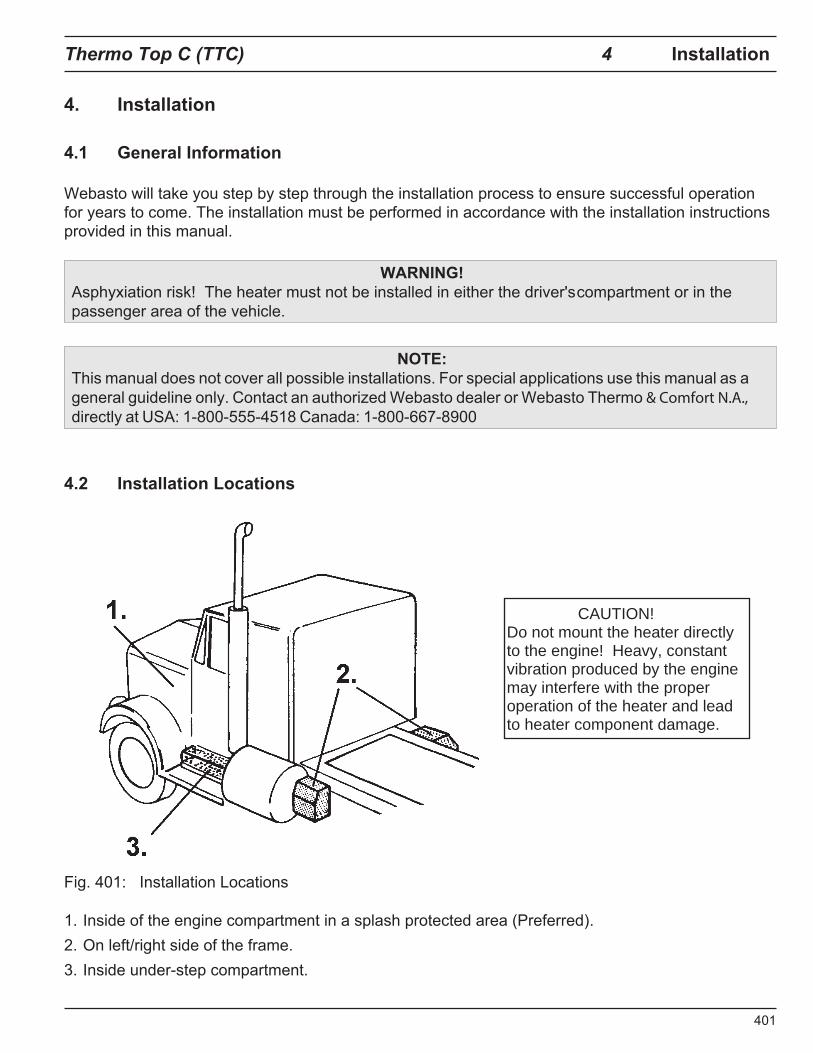
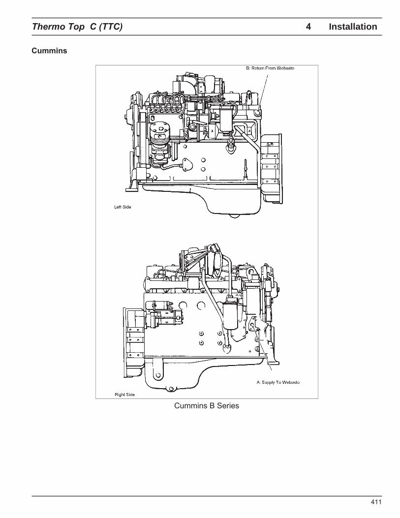
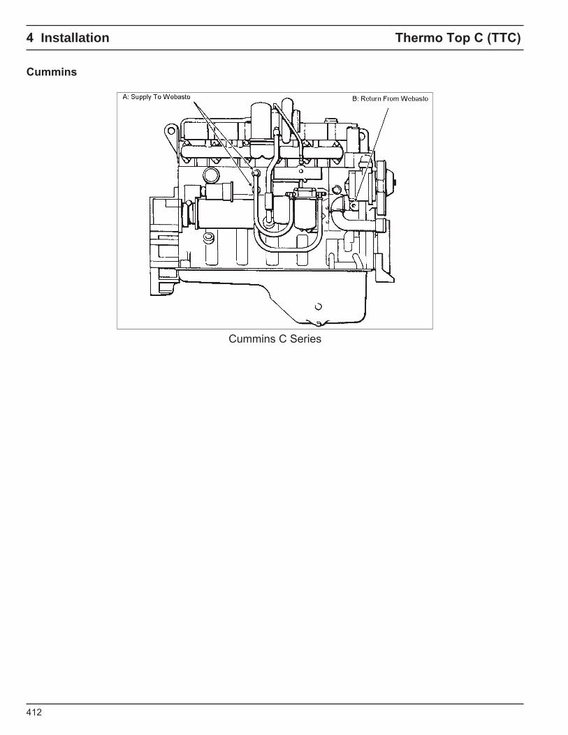
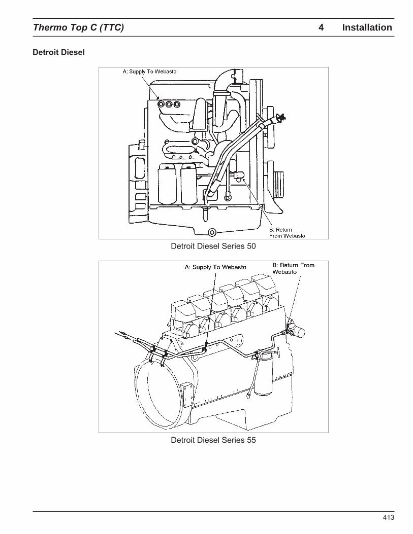
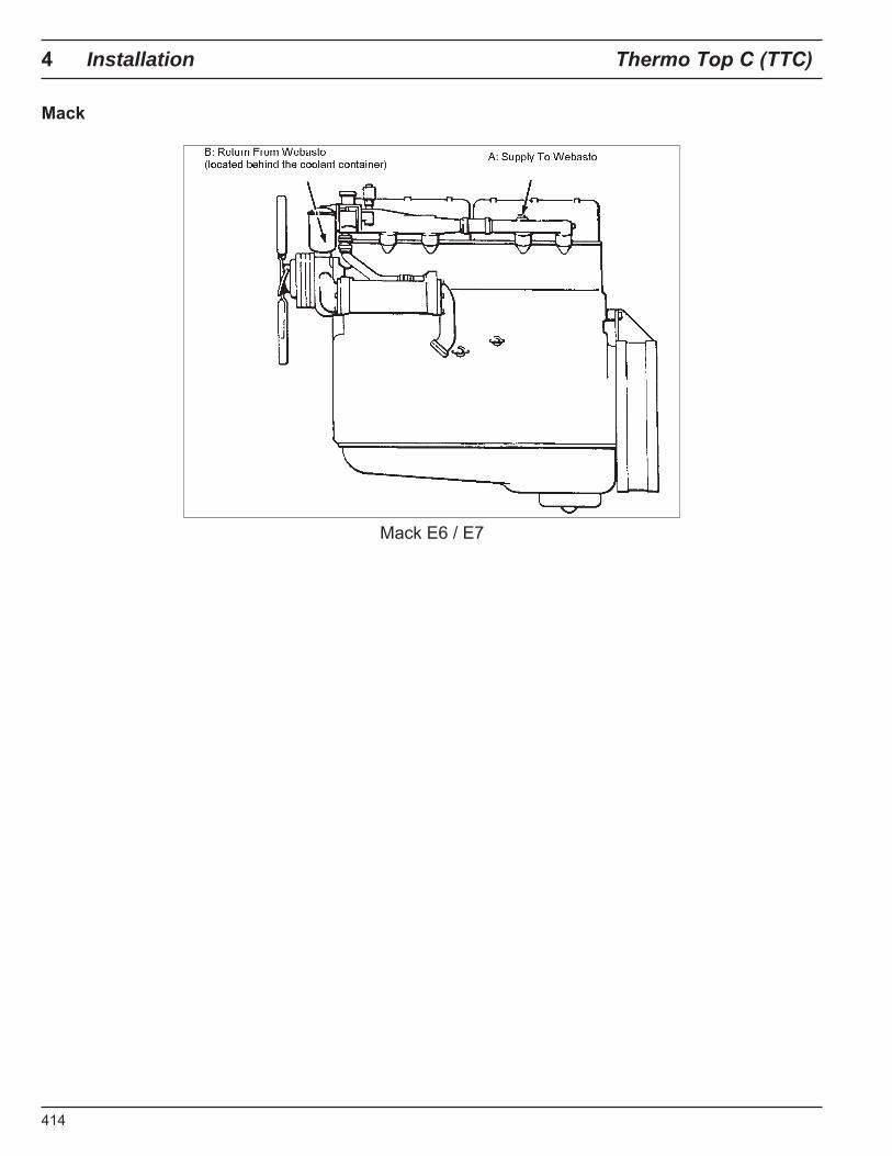
CAUTION!Do not mount the heater directly to the engine! Heavy, constant vibration produced by the engine may interfere with the proper operation of the heater and lead to heater component damage.
P-
"
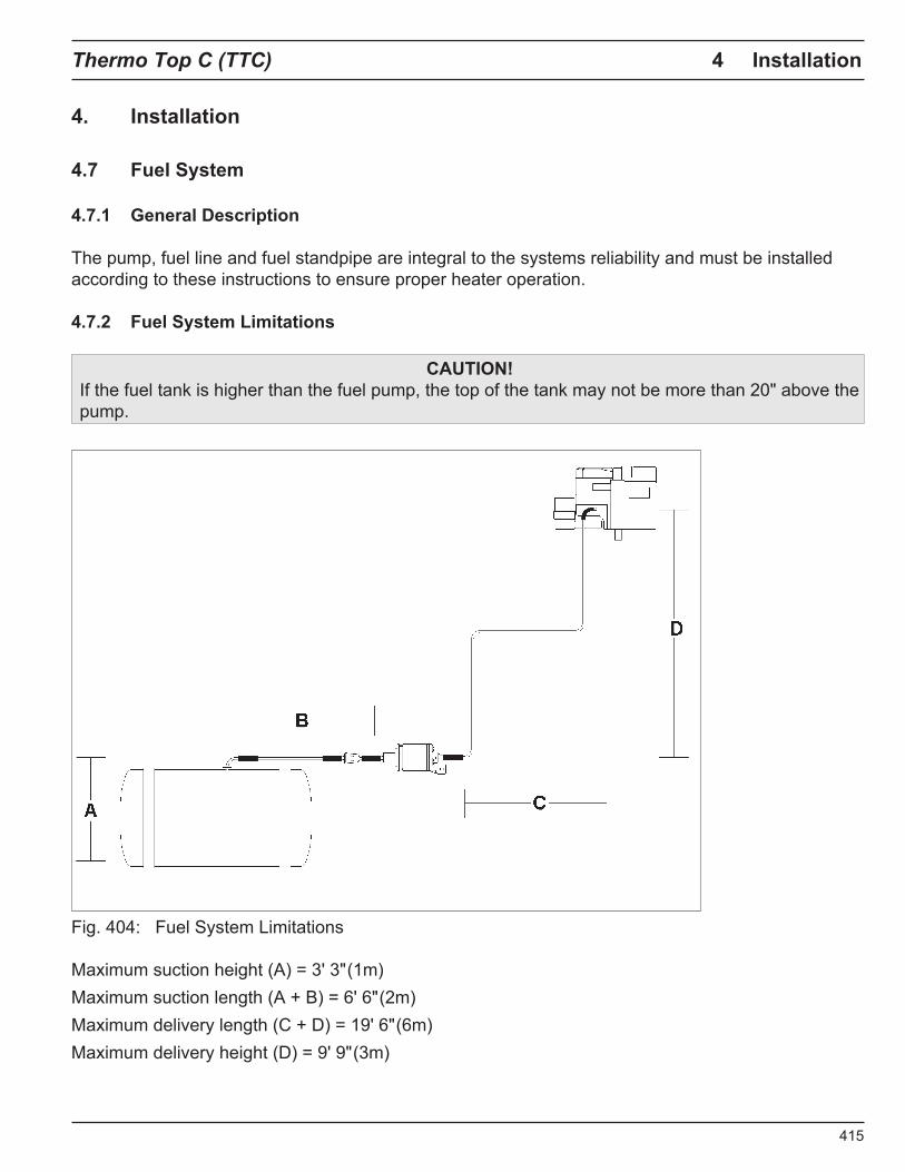
) Installation
Installation
TC) 4 Installation
Installation
Installation
Installation
Installation
Installation
"
)
"
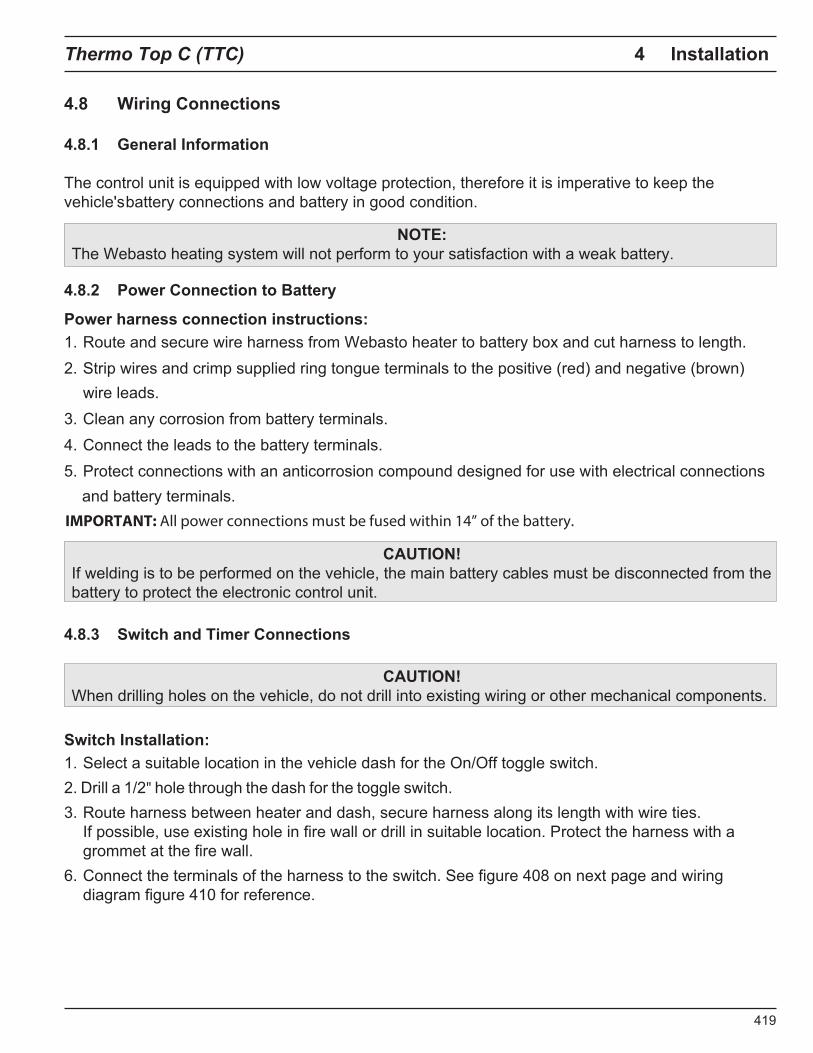
IMPORTANT: All power connections must be fused within 14” of the battery.
4 Installation Thermo Top (TTC)
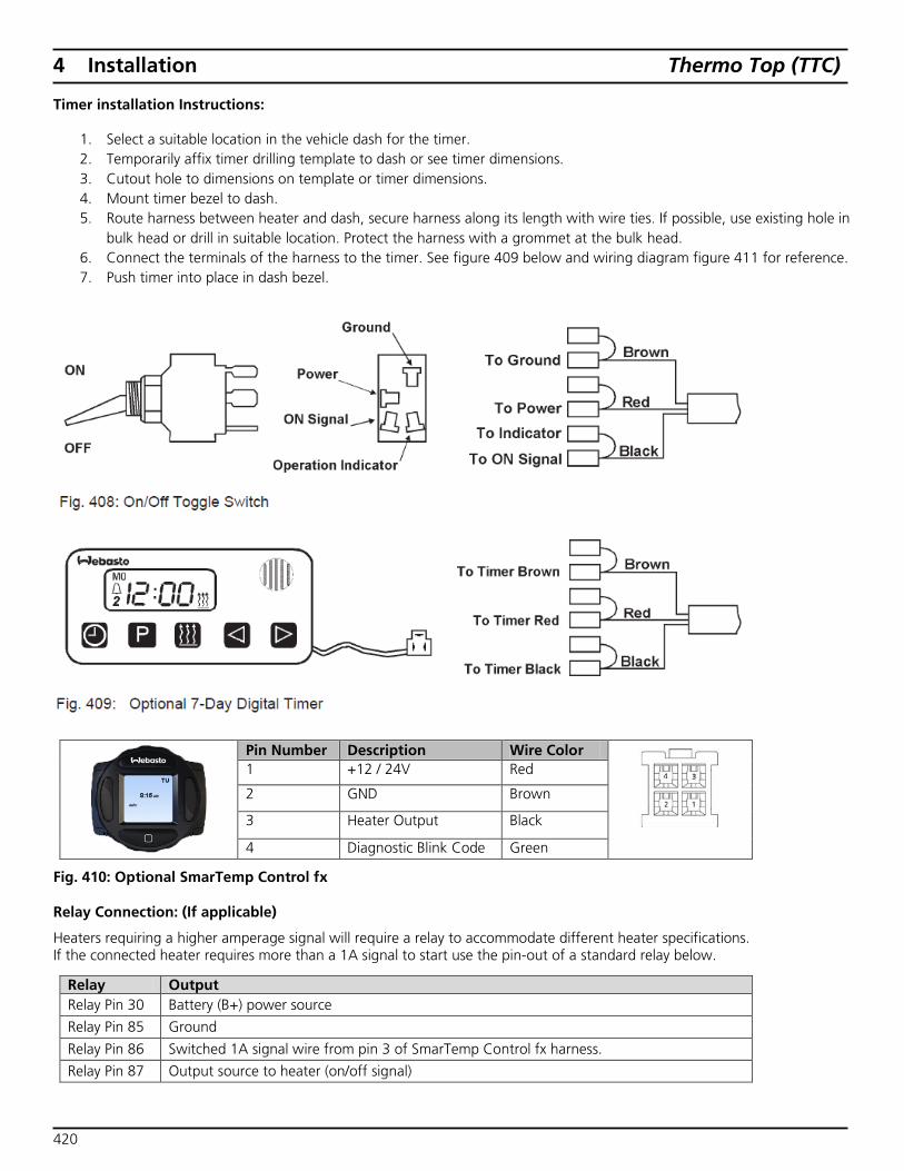
Timer installation Instructions:
1. Select a suitable location in the vehicle dash for the timer. 2. Temporarily affix timer drilling template to dash or see timer dimensions. 3. Cutout hole to dimensions on template or timer dimensions. 4. Mount timer bezel to dash. 5. Route harness between heater and dash, secure harness along its length with wire ties. If possible, use existing hole in
bulk head or drill in suitable location. Protect the harness with a grommet at the bulk head. 6. Connect the terminals of the harness to the timer. See figure 409 below and wiring diagram figure 411 for reference. 7. Push timer into place in dash bezel.
Pin Number Description Wire Color
1 +12 / 24V Red
2 GND Brown
3 Heater Output Black
4 Diagnostic Blink Code Green
Fig. 410: Optional SmarTemp Control fx
Relay Connection: (If applicable)
Heaters requiring a higher amperage signal will require a relay to accommodate different heater specifications. If the connected heater requires more than a 1A signal to start use the pin-out of a standard relay below.
Relay Output Relay Pin 30 Battery (B+) power source
Relay Pin 85 Ground
Relay Pin 86 Switched 1A signal wire from pin 3 of SmarTemp Control fx harness.
Relay Pin 87 Output source to heater (on/off signal)
420
4 Thermo Top (TTC) Installation
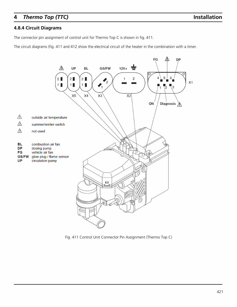
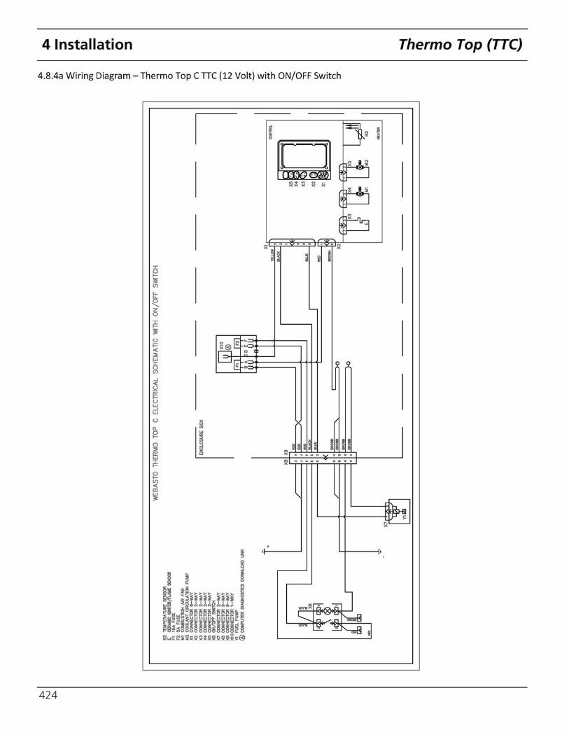
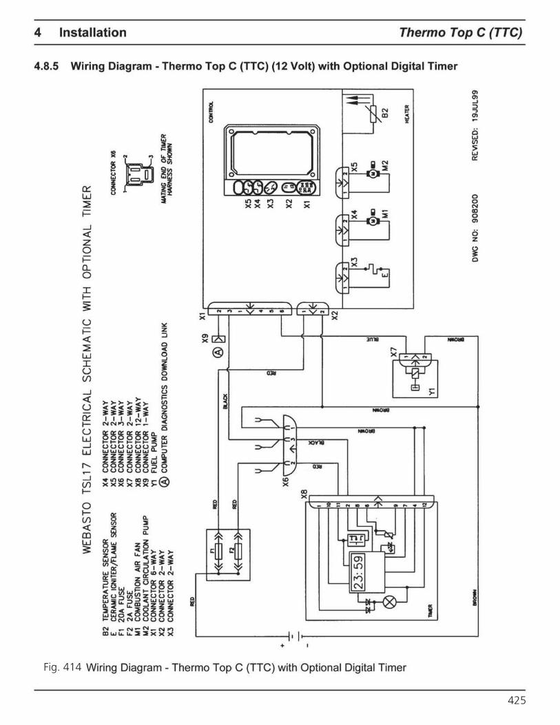
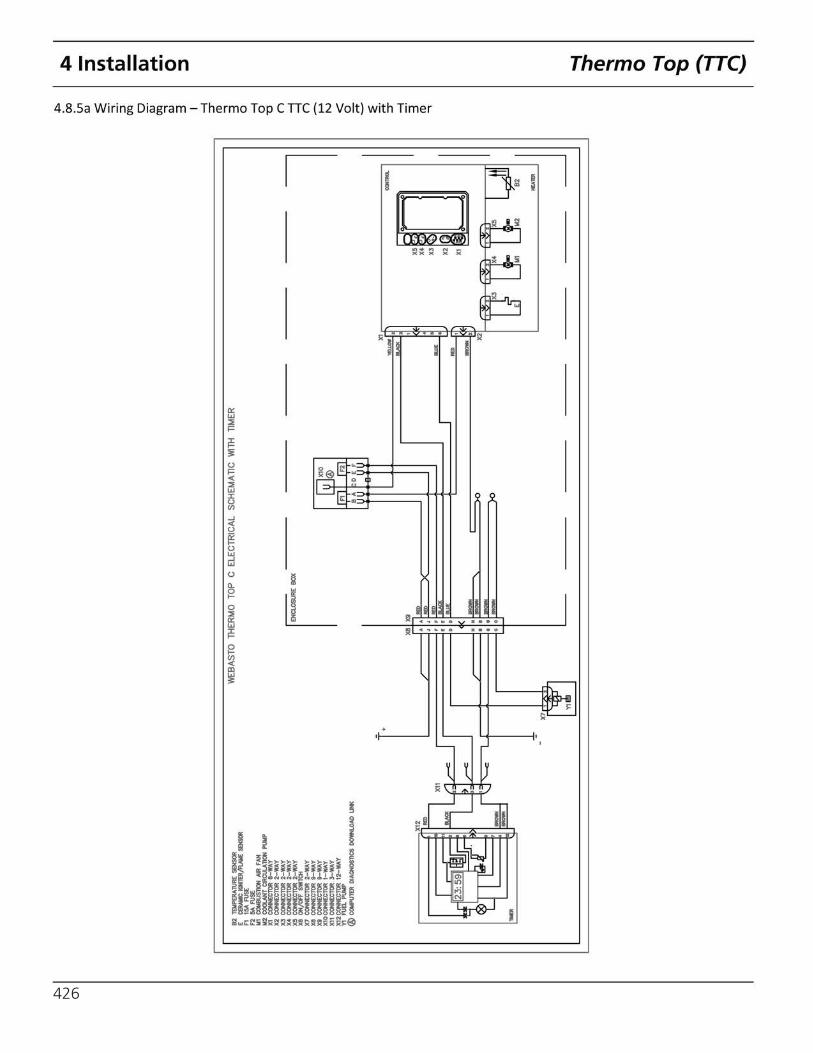
4.8.4 Circuit Diagrams
The connector pin assignment of control unit for Thermo Top C is shown in fig. 411.
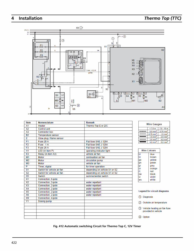
The circuit diagrams (fig. 411 and 412 show the electrical circuit of the heater in the combination with a timer.
Fig. 411 Control Unit Connector Pin Assignment (Thermo Top C)
421
4 Installation Thermo Top (TTC)
Fig. 412 Automatic switching Circuit for Thermo Top C, 12V Timer
422
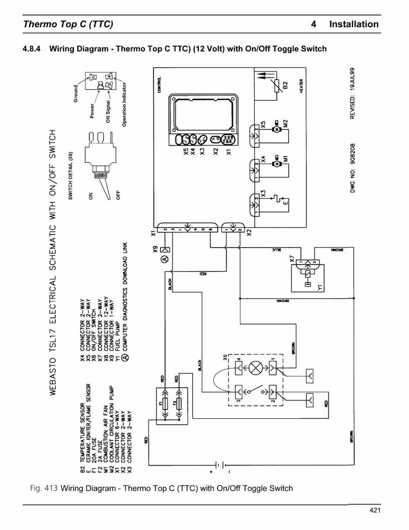
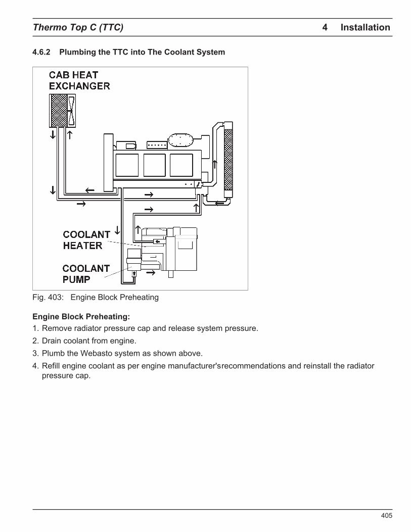
Fig. 413
.i::.
N .....
~
::::::!.
::
I co
0 a» co
.....
. Q
) 3 -l
::r
CD
...... 3 0 -l
0 "O
()
'=!
-l
()
..........
. :;: ;:::
:;: ::r 0 ::I - 0 ~ -l
0 co
co
CD
(/) :;: ;::::;:
()
::r
WE
BA
ST
O
TS
L 1
7
EL
EC
TR
ICA
L
SC
HE
MA
TIC
W
ITH
O
N/O
FF
S
WIT
CH
82
TE
MP
ER
ATU
RE
S
EN
SO
R
E
CER
AMIC
IG
NIT
ER
/FLA
ME
SE
NSO
R
F1
20
A F
US
E
F2
2
A F
US
E
Ml
CO
MB
US
TIO
N
AIR
F
AN
M
2 C
OO
LAN
T O
RC
ULA
TIO
N
PU
MP
X1
C
ON
NE
CTO
R
6-W
AY
X4
C
ON
NE
CTO
R
2-
WA
Y
X5
C
ON
NE
CTO
R
2-
WA
Y
X6
O
N /O
FF
S
V.H
CH
X
7 C
ON
NE
CTO
R
2-W
AY
X
8
CO
NN
EC
TOR
1
2-W
AY
X
9 C
ON
NE
CTO
R
1-W
AY
Y1
F
UE
L P
UM
P
SW
ITC
H D
ET
AIL
(X
6)
Gro
und
X2
C
ON
NE
CTO
R
2-W
AY
X
3
CO
NN
EC
TOR
2
-WA
Y
@ C
OM
PU
TER
D
IAG
NO
ST
ICS
D
OW
NLO
AD
LI
NK
O
pera
tion
Ind
icat
or
ACO
+
llf;O
8RO
ltl
RED
Am
8'.M
:K X
6
-,
41
~ ~
! I 1
I _
J lll
O'M
I
I
X9 X1f\""~~~~~~~~~~~~~~-,
@ D
l-----
12
CO
NT
llCll
~31
~I
X2
= I
XS
X
4
X.3
!1'i
X2
X1
OW
G
NO
: 9
08
20
8
o.
0 ~
l'
'o
82
H[A
T(l
l
RE
VIS
ED
: 1
9JU
L9
9
~
()0
~
~
~.
:::::s cc c sr cc ~ 3 -l ::::r
CD .., 3 0 -l
0 "C
0 :1 0 - -~ ....., <
0 ;::; - :E ;:::;: ::::r
0 :::::s - 0 ~ -l
0 cc
cc
CD "' :E ;:::;:
(') ::::r
:;!
CD ~ 0 O' "tl
()
--..
"""f
"""f
-52
~
::::J
(A -S» S»
:::::!': 0 ::::J
4
82
TEM
PER
A nJA
E S
EM
stft
E
CE
RAM
IC I
GN
!IR
/IUM
E S
DIS
llR
n 15
A F
USE
F2
SA F
USE
Il
l C
OllB
USl
lOH
AIR
FA
N
112
COO
LAN
T C
IRC
IJU
llON
PIM
' X
I <X
IHN
EC10
R &
-WA
Y
X2
CO
NIE
CTO
R 2
-WA
Y
XJ
CO
NIE
C10
R 2
-WA
Y
X4
CO
NIE
C10
R 2
-WA
Y
X!I
CO
NIE
C10
R 2
-WA
Y
XII OH/~ S
YC
ltH
1:1
OO
NN
EC10
R 2
-WA
Y
lC8
CO
NN
EC10
R ~WAY
XII
OO
NN
EC10
R ~WAY
XIO
CO
NN
EC
10R
I-W
AY
Y1
FU
El.
PIJM
P ®
OO
llPllT
ER
ov.
GN
OS
llCS
OO
YH.O
AI>
lM(
""
WEB
ASTO
TH
ERM
O
TOP
C E
LEC
TRIC
AL
SC
HE
MA
TIC
WIT
H
ON
/OF
F S
WIT
CH
r~
X8
I X
9
~
l I -
:[]
XJ
'
X2
'
I X
I
!""
00
:p,
. Q
) ~
:::::!.
:::J
O'Q
0 c;·
O'Q
... Q) 3 I -i
;;;;
ro
... 3 0 -i
0 -0
n =1 n .......
N <
0 ~
:E
;:::;:
;;;;
0 z -0 "Tl
"Tl
Vl :E
;::::;:
n ;;;;
~ - :::::
s "' r+ DJ - - DJ r+ -·
0 :::::s :;!
tb ~ 0 Qi
"'O "=i
~
....__
5
4 ~
::::!.
::
J co
0 or
co
...,
Q
) 3 -I
::r
CD
...,
3 0 -I
0 "O
()
...-.. =1 ()
......... :E ~
::r 0 "E.
5·
::J
Q) 0 ce· ~
Q) =!
3 CD ...,
+
WE
BA
STO
TS
L 17
E
LEC
TR
ICA
L S
CH
EM
A T
IC
WIT
H
OP
TIO
NA
L TI
ME
R
82
TE
MP
ER
ATU
RE
S
EN
SO
R
E
CERA
MIC
IG
NIT
ER/F
LAM
E SE
NSO
R F1
2
0A
FU
SE
F
2 2
A F
US
E
M1
CO
MB
US
TIO
N
AIR
F
AN
M
2 C
OO
LAN
T C
IRC
ULA
TIQ
ll.I
PU
MP
X1
C
ON
NE
CTO
R
6-W
AY
X
2
CO
NN
EC
TOR
2
-WA
Y
X3
C
ON
NE
CTO
R
2-W
AY
11£D
IE>
RED
.--~~~~~~~~--,XS
'----------1
12
1
1M
ll -
X4
CO
NN
EC
TOR
2
-WA
Y
XS
C
ON
NE
CTO
R
2-W
AY
X
6 C
ON
NE
CTO
R
3-W
AY
X
7
CO
NN
EC
TOR
2
-WA
Y
XB
C
ON
NE
CTO
R
12
-WA
Y
X9
C
ON
NE
CTO
R
1-W
AY
Y1
F
UE
L P
UM
P
@ C
OM
PU
TER
D
IAG
NO
STI
CS
D
OW
NLO
AD
LI
NK
CON
NEC
TOR
X&
u:
MAn
NG (
HO
OF
nUER
H
AR
N£S
S SH
OW
N
X9
X1
'
aAO
C
i @
l?J-
-jzf
) __
__
_ _
ll
CO
ll'll
lOl
0 0.
; X
6
X2
I II
= I
X5
X4
X3~
X2
X1
owe
NO
: 9
oa
20
0
P' Ou
82
Ht:
Alt
ll
RE
VIS
ED
: 1
9JU
L9
9
""
I ~
!» U'I ~
::::!. :::s
cc c I»
cc
G1 3 -t
::r
CD 3 0 -t
0 'C
0 ~
0 - -..... N <
0 ;::; - ~ ;+
::r
0 'C
:::!:
0 :::s
I» c cc ;: - ~ 3 CD .,
- ::::s tA Dr - m e.
0 ::::s :;!
C'D ~ 0 "Ci
"'O
0 --.. .....
rj
~
26
82
TE
MP
DtA
'llJR
E S
ENSO
R
E
CO
WIC
IClllER~ s
ocsa
t n
1
M F
USE
F2
!IA
FU
SE
W1
CX'.li
l9US
TION
JiM
. FA
H
112
ooot
NIT
CIR
CU
lAllO
N P
IJllP
X1
CO
NN
ECTO
R &
-WA
Y
X2
CO
NN
ECTO
R 2
-WA
Y
X3
CO
NN
EClll
R 2
-WA
Y
X4 C
ON
NEC
Tat
2-W
AY
XS
CO
NNEC
TOR
2-W
AY
X
8 O
N/C
fT S
'M1C
H
'1:1
CON
HEC
TOR
2-W
AY
X
S C
XN
EC
TOR
t-W
AY
X
I O
OfK
CT
OR
9-W
AY
X
10C
CH
tEC
TO
R 1
-WA
Y
X11
COfre
CCTO
R 3-
WA
Y
X12
CX
HtE
CTO
R 1
2-W
AY
Y1
FU
Ei. P
IJllP
@
CO
llPll1
tR C
CA
CN
OS
llCS
DO
'llNLO
AD
U«
WE
BA
STO
lH
ER
MO
TO
P
C E
LEC
TR
ICA
L S
CH
EM
AT
IC
WllH
TI
ME
R
r-X
lll
lC9
I I
11
I
"""
I I
!!!!!!
!! - Tf:
.. - ..
+>-
00
V1
Q) ~
::::!.
:::
J O
'Q
0 c;·
O'Q
... Q) 3 I -i
;;;;
ro
... 3 0 -i
0 -0
n
l =1 n ....
... N
<
0 ~
:E
-~~
l
~[]
:~ --
;:::;:
;;;;
::!
3 ro ...
~ - ::::
s "' ,....
QJ - - QJ ,....
-·
0 ::::s :;!
tb ~ 0 Qi
-0 '=i
~
....__
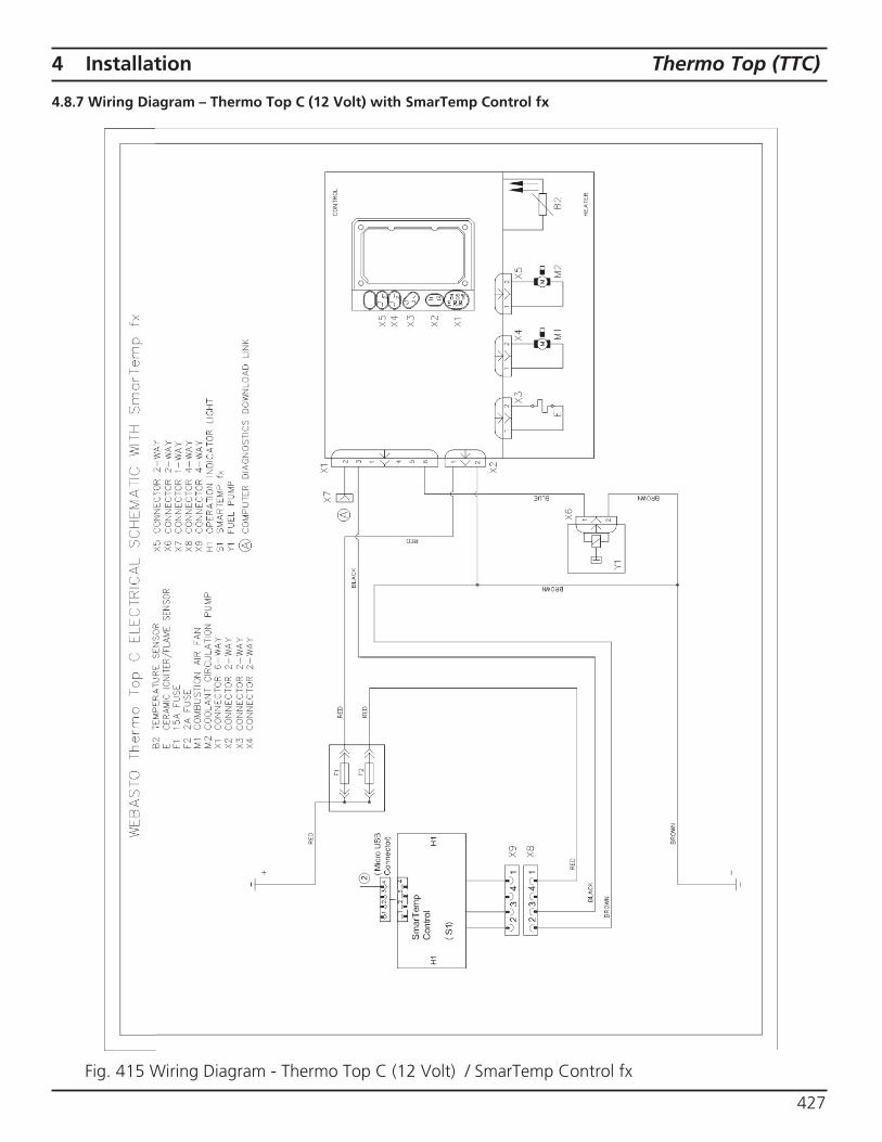
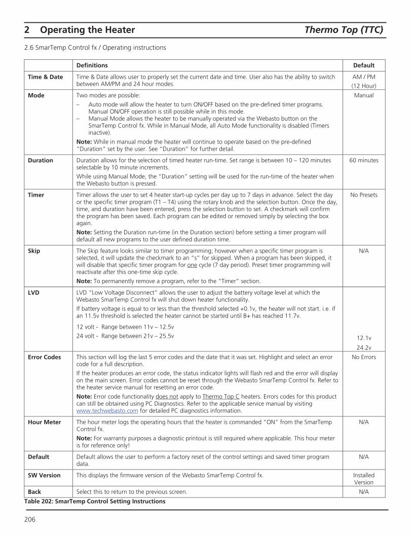
Thermo Top (TTC) 4 Installation
4.8.7 Wiring Diagram – Thermo Top C (12 Volt) with SmarTemp Control fx
27
5
Instant Heat
8
& Comfort N.A., Inc
9
Instant On
1320920A B


Org. 3/2000 Rev. 2/2014 907512
Webasto Thermo & Comfort N.A., Inc. 15083 North Road Fenton, MI 48430 Technical Assistance Hotline USA: (800) 860-7866 Canada: (800) 667-8900 www.webasto.us www.techwebasto.com
Recommended