Arnold Schwarzenegger Governor
OPEN AUTOMATED DEMAND RESPONSECOMMUNICATIONS SPECIFICATION
(Version 1.0)
Prepared For: California Energy Commission Public Interest Energy Research Program Prepared By: Lawrence Berkeley National Laboratory Akuacom
PIER
FIN
AL
PRO
JEC
T R
EPO
RT
April 2009
CEC-500-2009-063


Prepared By: Demand Response Research Center Lawrence Berkeley National Laboratory Mary Ann Piette Girish Ghatikar Sila Kiliccote Ed Koch Dan Hennage Peter Palensky Charles McParland Berkeley, California 94720 Commission Contract No. 500-03-026
Prepared For: Public Interest Energy Research (PIER)
California Energy Commission
Ivin Rhyne
Project Manager
Kristy Chew/ Chris Scruton Contract Manager
Pedro Gomez / Norm Bourassa
Program Area Lead
Energy Systems Integration / Buildings
Mike Gravely
Office Manager
Energy Systems Research
Martha Krebs, Ph.D. PIER Director
Thom Kelly
Deputy Director
ENERGY RESEARCH & DEVELOPMENT DIVISION
Melissa Jones
Executive Director

DISCLAIMER
This report was prepared as the result of work sponsored by the California Energy Commission. It does not necessarily represent the views of the Energy Commission, its employees or the State of California. The Energy Commission, the State of California, its employees, contractors and subcontractors make no warrant, express or implied, and assume no legal liability for the information in this report; nor does any party represent that the uses of this information will not infringe upon privately owned rights. This report has not been approved or disapproved by the California Energy Commission nor has the California Energy Commission passed upon the accuracy or adequacy of the information in this report.
Disclaimer This document was prepared as an account of work sponsored by the United States
Government. While this document is believed to contain correct information, neither the
United States Government nor any agency thereof, nor The Regents of the University of
California, nor any of their employees, makes any warranty, express or implied, or
assumes any legal responsibility for the accuracy, completeness, or usefulness of any
information, apparatus, product, or process disclosed, or represents that its use would
not infringe privately owned rights. Reference herein to any specific commercial
product, process, or service by its trade name, trademark, manufacturer, or otherwise,
does not necessarily constitute or imply its endorsement, recommendation, or favoring
by the United States Government or any agency thereof, or The Regents of the
University of California. The views and opinions of authors expressed herein do not
necessarily state or reflect those of the United States Government or any agency thereof
or The Regents of the University of California.
Ernest Orlando Lawrence Berkeley National Laboratory
Attention: Mary Ann Piette
Demand Response Research Center
One Cyclotron Road, MS 90R3111
Berkeley, CA 94720. United States of America
E‐mail: [email protected]
Website: http://openadr.lbl.gov/

Acknowledgements
The work described in this report was coordinated by the Demand Response Research
Center and funded by the California Energy Commission (Energy Commission), Public
Interest Energy Research (PIER) Program, under Work for Others Contract No. 500‐03‐
026 and by the U.S. Department of Energy under Contract No. DE‐AC02‐05CH11231.
The authors would like to thank the Technical Advisory Group (listed below) for their
assistance in this document. The authors also want to acknowledge Ron Hofmann and
Roger Levy, consultants to the California Energy Commission and LBNL, and David
Watson, former LBNL employee, for their ongoing support. The authors also want to
thank Nance Matson for her assistance in finalizing this document.
Please cite this report as follows:
Piette, Mary Ann, Girish Ghatikar, Sila Kiliccote, Ed Koch, Dan Hennage, Peter
Palensky, and Charles McParland. 2009. Open Automated Demand Response
Communications Specification (Version 1.0). California Energy Commission, PIER
Program. CEC‐500‐2009‐063.
i

ii

Preface
The California Energy Commission’s Public Interest Energy Research (PIER) Program
supports public interest energy research and development that will help improve the
quality of life in California by bringing environmentally safe, affordable, and reliable
energy services and products to the marketplace.
The PIER Program conducts public interest research, development, and demonstration
(RD&D) projects to benefit California.
The PIER Program strives to conduct the most promising public interest energy research
by partnering with RD&D entities, including individuals, businesses, utilities, and
public or private research institutions.
PIER funding efforts are focused on the following RD&D program areas:
Buildings End‐Use Energy Efficiency
Energy Innovations Small Grants
Energy‐Related Environmental Research
Energy Systems Integration
Environmentally Preferred Advanced Generation
Industrial/Agricultural/Water End‐Use Energy Efficiency
Renewable Energy Technologies
Transportation
Open Automated Demand Response Communications Specification is the final report
for the Open Automated Demand Response project by the Demand Response Research
Center (Contract Number 500‐03‐026), conducted by Lawrence Berkeley National
Laboratory. The information from this project contributes to PIER’s Energy Systems
Integration Program.
For more information about the PIER Program, please visit the Energy Commission’s
Website at www.energy.ca.gov/research/ or contact the Energy Commission at
916‐654‐4878.
iii

iv

Table of Contents ABSTRACT ................................................................................................................................................ XI
EXECUTIVE SUMMARY .......................................................................................................................... 1
PATENTS...................................................................................................................................................... 3
PARTICIPANTS .......................................................................................................................................... 4
TECHNICAL ADVISORY GROUP........................................................................................................... 4
1.0 INTRODUCTION.................................................................................................................................. 5
2.0 SCOPE .................................................................................................................................................... 9
2.1. Purpose .................................................................................................................................................. 9 2.2. Reason ................................................................................................................................................... 9
3.0 NORMATIVE REFERENCES........................................................................................................... 11
4.0 USE OF THIS SPECIFICATION....................................................................................................... 13
4.1. Implementing Demand Response Automation Server Interface.......................................................... 13 4.2. Proper Use and Citation....................................................................................................................... 15
5.0 DEMAND RESPONSE AUTOMATION SERVER REQUIREMENTS ........................................ 17
5.1. General Role of Demand Response Automation Server in Demand Response Programs and Dynamic Pricing .............................................................................................................................................. 17
5.2. Use Cases .............................................................................................................................................. 17 5.2.1.Use Case Scenarios........................................................................................................................ 17 5.3 Use Case Scenarios................................................................................................................................. 18 5.3.1. Program Configuration................................................................................................................. 18 5.3.2.Generalized Use Cases for Demand Response Programs.............................................................. 19 5.4. Overall Requirements .......................................................................................................................... 32
6.0 SPECIFICATIONS.............................................................................................................................. 33
6.1. Automated Demand Response Architecture........................................................................................ 33 6.2. General Requirements ......................................................................................................................... 35 6.3. Common Requirements ....................................................................................................................... 36 6.3.1. Demand Response Automation Server User Accounts and Security Roles ............................... 37 6.3.2. Logs and Reports ...................................................................................................................... 37 The DRAS Client Communications State............................................................................................. 38 All Transactions With the DRAS.......................................................................................................... 38 Exceptions and Alarm Conditions ....................................................................................................... 38 6.3.3. Operator Notifications .............................................................................................................. 38 6.3.4. Testing ...................................................................................................................................... 39 6.4. Introduction to Data Entities Used By Interface Functions ................................................................. 39 6.4.1. Data Entities in Support of Utility and ISO Use Case Actions ................................................. 40 Utility Issues DR Event........................................................................................................................ 41 Utility Configuration of DRAS ............................................................................................................ 43 Utility Manages Bids ........................................................................................................................... 46 Utility gets Logs and Alarms ............................................................................................................... 46 6.4.2. Data Entities in Support of Participant Operator Functions.................................................... 47 Participant Configuration ................................................................................................................... 47 6.4.3. Data Entities in Support of Demand Response Automation Server Client Functions .......... 52
v

6.5. Demand Response Event Models ........................................................................................................ 53 6.5.1. Utility or ISO View of a Demand Response Event................................................................ 54 6.5.2. Propagation of Demand Response Events by the Demand Response Automation Server .... 57 6.5.3. Demand Response Automation Server Client View of Demand Response Events ................ 72 6.6. Demand Response Automated Bidding Models .................................................................................. 83
7.0 FUNCTIONAL SPECIFICATIONS ........................................................................................... 87
7.1. Utility or ISO Operator Functions ....................................................................................................... 87 7.1.1. Utility or ISO Handling Demand Response Events .............................................................. 87 7.1.2. Utility or ISO Support for Automated Bidding ..................................................................... 88 7.1.3. Utility or ISO Configure Demand Response Automation Server.......................................... 89 7.1.4. Utility or ISO Monitoring of Demand Response Automation Server Related Activities ....... 91 7.2. Demand Response Automation Server Client Functions..................................................................... 91 7.3. Participant Operator Functions ............................................................................................................ 93 7.3.1. Opting Out of Demand Response Events .............................................................................. 93 7.3.2. Submitting Feedback (Facility Status) to Demand Response Automation Server ................ 94 7.3.3. Automated Bidding ............................................................................................................... 94 7.3.4. Configuration of Participant Related Information in Demand Response Automation Server .. .............................................................................................................................................. 95 7.3.5. Monitoring of Demand Response Automation Server Related Activities.............................. 98 7.3.6. Installation and Testing of Demand Response Automation Server Clients .......................... 99
8.0 DETAILED DATA MODELS AND SCHEMAS .................................................................... 101
8.1. UtilityProgram................................................................................................................................... 101 8.2. UtilityDREvent.................................................................................................................................. 101 8.3. ResponseSchedule ............................................................................................................................. 101 8.4. ProgramConstraint............................................................................................................................. 101 8.5. ParticipantAccount ............................................................................................................................ 101 8.6. OptOutState ....................................................................................................................................... 101 8.7. Logs 101 8.8. Feedback............................................................................................................................................ 101 8.9. EventInfo ........................................................................................................................................... 102 8.10. DRASClient....................................................................................................................................... 102 8.11. Bid 102 8.12. EventState.......................................................................................................................................... 102
9.0 DETAILED APPLICATION PROGRAMMING INTERFACE SPECIFICATIONS................. 103
9.1. Utility Program Operator APIs.......................................................................................................... 103 9.2. Participant Operator APIs.................................................................................................................. 103 9.3. DRAS Client APIs............................................................................................................................. 103 9.3.1. Use of Simple REST Services to Exchange DR EventState Information............................. 104 9.3.2. Use of Simple SOAP Services to Exchange DR EventState Information ............................ 105 9.3.3. Use of BACnet Web Services to Exchange DR EventState Information ............................. 107
10.0 SECURITY POLICY................................................................................................................. 113
10.1. Scope 113 10.2. Access Control and Security Roles.................................................................................................... 113
11.0 FUTURE DEVELOPMENTS................................................................................................... 117
12.0 DEFINITIONS, ACRONYMS AND ABBREVIATIONS ...................................................... 119
APPENDIX A: XSD SCHEMA FILES ...................................................................................................... 1
APPENDIX B: WSDL INTERFACE FILES............................................................................................. 1
vi

APPENDIX C: SECURITY ANALYSIS AND REQUIREMENTS ........................................................ 1
C.1 Assumptions ............................................................................................................................................ 1 C.2 Existing Security Standards ..................................................................................................................... 1 C.3 DRAS Risk Context................................................................................................................................. 2 C.4 DRAS Sources of Risk ............................................................................................................................ 4 C.5 Adverse Risk-Related Effects .................................................................................................................. 5 C.6 Security Requirements ............................................................................................................................. 7
APPENDIX D: DR PROGRAM USE CASES........................................................................................... 1
D.1 General Use Case Definitions and Nomenclature.................................................................................... 1 D.1.1 Use Case Elements .......................................................................................................................... 1 D.2 Specific Use Cases ................................................................................................................................ 3 D.2.1 Critical Peak Pricing (CPP) ........................................................................................................... 3 D.2.2 Demand Bidding Program (DBP) ................................................................................................. 12 D.2.3 Capacity Bidding Program (CBP) ................................................................................................ 23 D.2.4 Base Interruptible Program (BIP)................................................................................................. 37 D.2.5 Peak Day Credit (PDC) ............................................................................................................... 47 D.2.6 DR Programs with Programmable Communicating Thermostat (PCT) ...................................... 56 D.2.7 Generic Real-Time Pricing Based Programs (RTP) ...................................................................... 61
vii

List of Figures
Figure 1. DRAS Client Interfaces ................................................................................ 14 Figure 2. Automated Generic Event-Based Program (GEBP) Use Case ..................... 24 Figure 3. Generic Bidding Process (GBP) ................................................................... 29 Figure 4. General Automated Events Architecture with Standalone DRAS................ 34 Figure 5. General Automated Bidding Architecture with Standalone DRAS.............. 34 Figure 6. Use Case References to Functional Specification ........................................ 35 Figure 7. Utility Issued DR Event Entity ..................................................................... 42 Figure 8. Utility Configuration Entities ....................................................................... 45 Figure 9. Utility Logs and Client Alarms..................................................................... 46 Figure 10. Participant Configuration Entities................................................................ 48 Figure 11. Participant Submit Bid Entity ...................................................................... 49 Figure 12. Participant Opt-Out Entities......................................................................... 50 Figure 13. Participant Feedback Entities....................................................................... 51 Figure 14. Client Alarms and Utility Logs.................................................................... 52 Figure 15. DRAS Client DR Event State Entities ......................................................... 53 Figure 16. DR Event Model (Utility or ISO View)....................................................... 55 Figure 17. State Transition Diagram ............................................................................. 55 Figure 18. Relevant Attributes and Structures for Event Propagation .......................... 59 Figure 19. Sample Configuration - Participant Accounts and DRAS Clients............... 60 Figure 20. DR Event Propagation for Program P2–All Participant Accounts .............. 61 Figure 21. DR Event Propagation for Program P2–Specific Participant Accounts A3,
A4................................................................................................................. 62 Figure 22. DR Event Propagation for Program P1–Specific Participant Account A1.. 63 Figure 23. DR Event Propagation for Program P2–Groups G2, G4 ............................. 64 Figure 24. DR Event Propagation for Program P2–Specific DRAS Clients C1, C4, C5
65 Figure 25. DR Event Propagation for Program P2–Specific Locations L1, L3............ 66 Figure 26. DR Event Propagation for Program P2–Groups G2 and Participants A4
Specified ...................................................................................................... 67 Figure 27. DR Event Constraint Model (Which DRAS Clients Receive the Event) .... 69 Figure 28. Program Constraints and Filters................................................................... 70 Figure 29. DR Event Window Depending Upon Filter Constraints.............................. 71 Figure 30. DR Event Notification Time Depending Upon Filter Constraints............... 72 Figure 31. DR Event Duration Depending Upon Duration Constraints........................ 72 Figure 32. PUSH Model Sequence Diagram................................................................. 74 Figure 33. PULL Model Sequence Diagram................................................................. 74 Figure 34. DR Event State Model (Simple Client View).............................................. 80 Figure 35. DR Event Model (Utility or ISO View)....................................................... 80 Figure 36. Transition Diagram for a General DR Event ............................................... 82 Figure 37. DRAS Client DR Event State Simple DRAS Client State Transition
Diagram........................................................................................................ 83 Figure 38. State Transition Diagram for a Participant’s Bid State................................ 84 Figure 39. Bidding Sequence Diagram ......................................................................... 85
viii
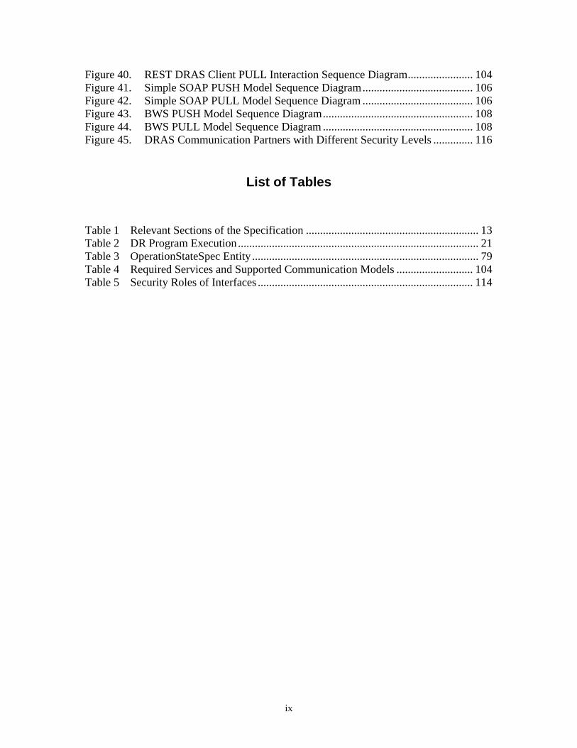
Figure 40. REST DRAS Client PULL Interaction Sequence Diagram....................... 104 Figure 41. Simple SOAP PUSH Model Sequence Diagram....................................... 106 Figure 42. Simple SOAP PULL Model Sequence Diagram ....................................... 106 Figure 43. BWS PUSH Model Sequence Diagram..................................................... 108 Figure 44. BWS PULL Model Sequence Diagram ..................................................... 108 Figure 45. DRAS Communication Partners with Different Security Levels .............. 116
List of Tables
Table 1 Relevant Sections of the Specification ............................................................. 13 Table 2 DR Program Execution..................................................................................... 21 Table 3 OperationStateSpec Entity ................................................................................ 79 Table 4 Required Services and Supported Communication Models ........................... 104 Table 5 Security Roles of Interfaces ............................................................................ 114
ix

x

Abstract
The development of the Open Automated Demand Response Communications
Specification, also known as OpenADR or Open Auto‐DR, began in 2002 following the
California electricity crisis. This specification describes an open standards‐based
communications data model designed to promote common information exchange
between the utility or Independent System Operator and electric customers using
demand response price and reliability signals. OpenADR is one element of the Smart
Grid information and communications technologies that are being developed to
improve optimization between electric supply and demand. The intention of the open
automated demand response communications data model is to provide interoperable
signals to building and industrial control systems that are pre‐programmed to take
action based on a demand response signal, enabling a demand response event to be fully
automated, with no manual intervention. The concept of an open specification is
intended to allow anyone to implement the signaling systems, the automation server, or
the automation clients. This communication specification is an essential enabling
technology for California’s future electrical grid. OpenADR will provide benefits to
California by both increasing the number of facilities that participate in demand
response, and reducing the cost to conduct frequent and persistent participation in
demand response. The work has been carried out by the Demand Response Research
Center (DRRC), which is managed by Lawrence Berkeley National Laboratory.
Keywords: Demand response, buildings, electricity use, automation, communications,
open standards, data models, specifications
xi

xii

Executive Summary
The development of the Open Automated Demand Response Communications
Specification, also known as OpenADR or Open Auto‐DR, began in 2002 following the
California electricity crisis. In California, the United States, and abroad, many utilities,
governments, electric independent systems operators and others have been pursuing
demand response to manage the growing demand for electricity and peak capacity of
the electric systems. Demand response (DR) has been defined as “…action taken to
reduce electricity demand in response to price, monetary incentives, or utility directives
so as to maintain reliable electric service or avoid high electricity prices1.ʺ OpenADR is
one element of the Smart Grid information and communications technologies that are
being developed to improve matching between electric supply and demand.
The research that led to this document was funded by the California Energy
Commission as part of its Public Interest Energy Research Program. The work has been
carried out by the Demand Response Research Center (DRRC) which is managed by
Lawrence Berkeley National Laboratory. The research explored the feasibility of
developing a low cost communications infrastructure to improve the reliability,
repeatability, robustness, and cost‐effectiveness of demand response in commercial
buildings. One key research question was: Could today’s communications and
information technologies be used to automate demand response operations of
commercial buildings using standardized electricity price and reliability signals? Six
years of research, development, and demonstration have led to this open data model.
This document outlines a communications exchange signals specification to enable
demand response in end‐use participant or customer systems.
Open Automated Demand Response is a communications data model designed to
facilitate sending and receiving of DR signals from a utility or independent system
operator to electric customers. The intention of the data model is to interact with
building and industrial control systems that are pre‐programmed to take action based
on a DR signal, enabling a demand response event to be fully automated, with no
manual intervention. Open specification is intended to allow anyone to implement the
signaling systems, the automation server or the automation clients.
Definition of Open Automated Demand Response Communications
OpenADR Communications have the following defining features:
1 U.S. Federal Energy Regulatory Commission (FERC), 2007 Assessment of Demand Response
and Advanced Metering, Staff Report, available: http://www.ferc.gov/legal/staff‐reports/09‐07‐
demand‐response.pdf .
1

Continuous, Secure, and Reliable ‐ Provides continuous, secure, and reliable two‐
way communications infrastructures where the clients at the end‐use site receive
and acknowledge to the DR automation server upon receiving the DR event
signals.
Translation ‐ Translates DR event information to continuous Internet signals to
facilitate DR automation. These signals are designed to interoperate with Energy
Management and Control Systems, lighting, or other end‐use controls.
Automation ‐ Receipt of the external signal is designed to initiate automation
through the use of pre‐programmed demand response strategies determined and
controlled by the end‐use participant.
Opt‐Out ‐ Provides opt‐out or override function to participants for a DR event if
the event comes at a time when reduction in end‐use services is not desirable by
participants.
Complete Data Model ‐ Describes a rich data model and architecture to
communicate price, reliability, and other DR activation signals.
Scalable Architecture ‐ Provides scalable communications architecture to
different forms of DR programs, end‐use buildings, and dynamic pricing.
Open Standards ‐ Open standards‐based technology such as Simple Object
Access Protocol (SOAP) and Web services form the basis of the communications
model.
OpenADR has been field tested in a number of DR programs in California. The scope of
this communications specification focuses on signals for DR events and prices. This
specification also covers the signaling data model and does not cover information
related to specific DR electric reduction or shifting strategies.
The Open Auto‐DR Communications Specification is designed to facilitate automating
demand response actions at the customer location, whether it is electric load shedding or
shifting. The question is often asked if the communications data model can be used for
continuous operations, every day. The answer is yes. Many emergency or reliability DR
events occur at specific times when the electric grid is strained. The Open Auto‐DR
communications are designed to coordinate such signals to building or industrial control
systems. Open Auto‐DR is also designed to provide continuous dynamic price signals
such as hourly day‐ahead or day‐of real time pricing. With such price information an
automated client can be designed to continuously monitor these prices and translate this
information into continuous automated control and response strategies within a facility.
Potential Benefits
OpenADR will provide benefits to California by both increasing the number of facilities
that participate in demand response, and reducing the cost to conduct frequent and
persistent participation in demand response. Furthermore OpenADR will improve the
feasibility of achieving the stateʹs policy goals of moving toward dynamic pricing, such
as critical peak or real time pricing, for all customers. Increasing participation in
2

demand response can reduce the need for new electric supply, reduces the need for new
transmission and distribution systems, and helps reduce overall electricity prices.
The OpenADR Communications Specification provides the following benefits:
Open Specification–Provides a standardized DR communications and signaling
infrastructure using open, non‐proprietary, industry‐approved data models that
can be implemented for both dynamic prices and DR emergency or reliability
events.
Flexibility–Provides open communications interfaces and protocols that are
flexible, platform‐independent, interoperable, and transparent to end‐to‐end
technologies and software systems.
Innovation and Interoperability–Encourages open innovation and
interoperability, and allows controls and communications within a facility or
enterprise to build on existing strategies to reduce technology operation and
maintenance costs, stranded assets, and obsolesce in technology.
Ease of Integration–Facilitates integration of common Energy Management and
Control Systems (EMCS), centralized lighting, and other end‐use devices that can
receive a relay or Internet signals (such as eXtensible Markup Languge [XML]).
Remote Access– Facilitates opt‐out or override functions through a participant
Web portal to manage standardized DR‐related operation modes to DR strategies
and control systems.
Future Research
The Demand Response Research Center will continue to conduct research to support
broader development and deployment of OpenADR. Future work will include
continued collaboration with formal industry standards development organizations to
harmonize these data models with related efforts. The Demand Response Research
Center will also continue to evaluate end‐use DR control strategies for homes, large and
small commercial buildings, and industrial facilities.
Patents
Attention is called to the possibility that implementation of this specification may
require use of subject matter covered by patent rights. By publication of this
specification, no position is taken with respect to the existence or validity of any patent
rights in connection therewith. The California Energy Commission, Lawrence Berkeley
National Laboratory, and the Demand Response Research Center shall not be
responsible for identifying patents or patent applications for which a license may be
required to implement this specification or for conducting inquiries into the legal
validity or scope of those patents that are brought to its attention.
3

4
Participants
The OpenADR Working Group had the following members:
Ed Koch, Chair, Akuacom Mary Ann Piette, LBNL
Girish Ghatikar, LBNL Peter Palnesky, Univ. of Pretoria
Dan Hennage, Akuacom David Holmberg, NIST
Sila Kiliccote, LBNL Dave Robin, Automated Logic Controls
Jim Butler, Cimetrics Charles McParland, LBNL
Technical Advisory Group
The following members of the Technical Advisory Group (TAG) members had executive
oversight of the OpenADR specification and contributed by review and approval of the
specification. Some organizations and affiliations have deputies for continued
participation and voting.
Organization Member Pacific Gas and Electricity Peter Chan Pacific Gas and Electricity Albert Chiu Southern California Edison Kevin G. Wood Southern California Edison Eric Parker San Diego Gas and Electric Terry Mohn San Diego Gas and Electric Julia Mendoza California Independent Systems Operator Walt Johnson California Independent Systems Operator John Goodin National Institute of Standards and Technology David Holmberg California Energy Commission Ivin Rhyne Levy Associates Roger Levy California Institute of Energy and Environment Ron Hofmann California Institute of Energy and Environment Gaymond Yee University of California Berkeley Nate Ota University of California Berkeley Alex Do Grid Net David Watson Sacramento Municipal Utility District Alvaro Mendoza
Electric Power Research Institute Bill Howe Electric Power Research Institute Chuck Thomas EnerNex Corporation Eric Gunther EnerNex Corporation Grant Gilchrist

1.0 Introduction The development of the Open Automated Demand Response Communications
Specification, also known as OpenADR or Open Auto‐DR, began in 2002 following the
California electricity crisis. In California, the United States, and abroad many utilities,
governments, electric Independent Systems Operators and others have been pursuing
demand response to manage the growing demand for electricity and peak capacity of
the electric systems. Demand Response (DR) has been defined as “…action taken to
reduce electricity demand in response to price, monetary incentives, or utility directives
so as to maintain reliable electric service or avoid high electricity prices1 .ʺ OpenADR is
one element of the Smart Grid information and communications technologies that are
being developed to improve optimization between electric supply and demand.
The research that led to this document was funded by the California Energy
Commission’s Public Interest Energy Research Program. The work has been carried out
by the Demand Response Research Center (DRRC), which is managed by Lawrence
Berkeley National Laboratory. The initial goal of the research was to explore the
feasibility of developing a low cost communications infrastructure to improve the
reliability, repeatability, robustness, and cost‐effectiveness of demand response in
commercial buildings. One key research question was: could today’s communications
and information technologies be used to automate demand response operations of
commercial buildings using standardized electricity price and reliability signals? Six
years of research, development, and demonstration have led to this open data model.
This document outlines a communications specification to exchange signals to enable
demand response in end‐use participant or customer systems.
Open Automated Demand Response is a communications data model designed to
facilitate sending and receiving DR signals from a utility or independent system
operator to electric customers. The intention of the data model is to interact with
building and industrial control systems that are pre‐programmed to take action based
on a DR signal, enabling a demand response event to be fully automated, with no
manual intervention. The OpenADR specification is a highly flexible infrastructure
design to facilitate common information exchange between a utility or Independent
System Operator (ISO) and their end‐use participants. The concept of an open
specification is intended to allow anyone to implement the signaling systems, providing
the automation server or the automation clients.
OpenADR Communications have the following defining features:
Continuous, Secure, and Reliable—Provides continuous, secure, and reliable
two‐way communications infrastructures where the clients at the end‐use site
1 U.S. Federal Energy Regulatory Commission (FERC), 2007 Assessment of Demand Response
and Advanced Metering, Staff Report, available: http://www.ferc.gov/legal/staff‐reports/09‐07‐
demand‐response.pdf.
5

receive and acknowledge to the DR automation sever upon receiving the DR
event signals.
Translation—Translates DR event information to continuous Internet signals to
facilitate DR automation. These signals are designed to interoperate with Energy
Management and Control Systems, lighting, or other end‐use controls.
Automation—Receipt of the external signal is designed to initiate automation
through the use of pre‐programmed demand response strategies determined and
controlled by the end‐use participant.
Opt‐Out—Provides opt‐out or override function to participants for a DR event if
the event comes at a time when reduction in end‐use services is not desirable.
Complete Data Model—Describes a rich data model and architecture to
communicate price, reliability, and other DR activation signals.
Scalable Architecture—Provides scalable communications architecture to
different forms of DR programs, end‐use buildings, and dynamic pricing.
Open Standards—Open standards‐based technology such as Simple Object
Access Protocol (SOAP) and Web services form the basis of the communications
model.
The authors refer to OpenADR as a “communications data model” to facilitate
information exchange between two end‐points, the utility or ISO and the facility. It is not
a protocol that specifies “bit‐structures” or “semantics” as some communications
protocols do. In some references the term “system,” “technology,” or “service” is used to
refer to the features of OpenADR.
OpenADR is in use in over 200 facilities in California providing an automation system
for several DR programs. These programs provide over 50 MW of DR in commercial
and industrial facilities. Several reports present the history of the automated DR
research2. While the scope of this communications specification focuses on signals for
DR events and prices, significant research has explored the controls strategies and
techniques to automated DR in commercial buildings3. This specification also covers the
signaling data model and does not cover information related to specific DR electric
2These reports are available at http://drrc.lbl.gov/drrc‐pubsall.html:
Piette, M.A., S. Kiliccote, G. Ghatikar, Design and Implementation of an Open,
Interoperable Automated Demand Response Infrastructure, Proceedings of the Grid‐
Interop Forum, October 2007, LBNL‐63665.
Koch, E., M.A. Piette, Architecture Concepts and Technical Issues for an Open,
Interoperable Automated Demand Response Infrastructure. Proceedings of the Grid‐
Interop Forum,. October 2007. LBNL‐63664.
Piette, M.A, D. Watson, N. Motegi, S. Kiliccote Automated Critical Peak Pricing Field
Tests: 2006 Pilot Program Description and Results. August, 2007. LBNL‐62218.
3 Motegi, N., M.A. Piette, D.S. Watson, S. Kiliccote, P. Xu. Introduction to Commercial Building
Control Strategies and Techniques for Demand Response. May 2007. LBNL‐59975.
6

reduction or shifting strategies. This communications specification has also been used
for automating DR in industrial facilities.
The Open Auto‐DR Communications Specification is designed to facilitate automating
demand response actions at the customer location, whether it is electric load shedding or
shifting. The authors are often asked if the communications data model can be used for
continuous operations. The answer is yes. Many emergency or reliability DR events
occur at specific times when the electric grid is strained. The Open Auto‐DR
communications are designed to coordinate such signals to building or industrial control
systems. Open Auto‐DR is also designed to provide continuous dynamic price signals
such as hourly day‐ahead or day‐of real time pricing. With such price information an
automated client can be designed to continuously monitor these prices and translate this
information into continuous automated control and response strategies within a facility.
The Open Auto‐DR Communications Specification provides the following benefits:
Open Specification–Provides a standardized DR communications and signaling
infrastructure using open, non‐proprietary, industry‐approved data models that
can be implemented for both dynamic prices and DR emergency or reliability
events.
Flexibility–Provides open communications interfaces and protocols that are
flexible, platform‐independent, interoperable, and transparent to end‐to‐end
technologies and software systems.
Innovation and Interoperability–Encourages open innovation and
interoperability, and allows controls and communications within a facility or
enterprise to build on existing strategies to reduce technology operation and
maintenance costs, stranded assets, and obsolesce in technology.
Ease of Integration–Facilitates integration of common Energy Management and
Control Systems (EMCS), centralized lighting, and other end‐use devices that can
receive a relay or Internet signals (such as XML).
Remote Access– Facilitates opt‐out or override functions through a participant
Web portal to manage standardized DR‐related operation modes to DR strategies
and control systems.
This report has the following structure. It begins with a section that outlines the scope,
purpose, and reason for the OpenADR specification, followed by an introduction to the
use of the specification and implementation concepts. Next are the DR Automation
Server (DRAS) requirements, component and functional specifications, followed by the
data models and schemas. The final sections discuss the application program interfaces,
security policies, and future plans. The future plans for OpenADR include additional
collaboration with formal standards groups. A set of appendices contain support schema
and interface files, a discussion of security issues, and DR program use cases.
7

8

2.0 Scope The Open Automated Demand Response Communications Specification defines the
interface to the functions and features of a Demand Response Automation Server
(DRAS) that is used to facilitate the automation of customer response to various
Demand Response programs and dynamic pricing through a communicating client. This
specification, referred to as OpenADR, also addresses how third parties such as utilities,
ISOs, energy and facility managers, aggregators, and hardware and software
manufacturers will interface to and utilize the functions of the DRAS in order to
automate various aspects of demand response (DR) programs and dynamic pricing.
2.1. Purpose The success of DR programs and dynamic pricing developed by utilities and ISOs
depend upon timely and reliable communications of events and information to
participants in the DR programs and dynamic pricing. If the DR communications being
sent can be automatically translated into load sheds or shifts by the participants without
the need for human intervention, then the process of participating in the demand
response programs can be made more cost effective, reliable, and easy to implement.
This OpenADR specification provides a software interoperability framework, benefit
facilities and public or private industry, enable innovation, and ease availability to the
widest range of facilities for the present and in the future. This specification describes a
suite of functions and capabilities that will allow the automated communications of DR
information exchange between utilities or ISOs and their participants. OpenADR is part
of the new Smart Grid technologies such as advanced information, control, and
communications technologies. These technologies are designed to help optimize the
linkages between electric supply and demand.
2.2. Reason Some participants such as aggregators and large corporations have wide spread
geographical operations across multiple electrical jurisdictions and thus must deal with
multiple utilities. Likewise utilities and ISOs must perform systems integration and
testing with each participant in a DR program. By using a standardized interchange
mechanism like the DRAS across multiple utilities and/or ISOs, the effort and cost of
participating in demand response programs and dynamic pricing will be lessened.
9

10

3.0 Normative References The following referenced documents are useful for the application of this document. For
dated references, only the edition cited applies. For undated references, the latest edition
of the referenced document (including any amendments or corrigenda) applies. The use
of the OpenADR specification does not require Building Automation Control NETwork
(BACnet) implementation.
“BACnet/WS Web Services Interface,” ANSI/ASHRAE Addendum Cc to
ANSI/ASHRAE Standard 135‐2004.
Request for Comment (RFC): RFC 2246: The Transport Layer Security (TLS)
Protocol Version 1.0, Internet Engineering Task Force, Jan 1999.
11

12

4.0 Use of This Specification
This document is designed to specify a set of functions that must be implemented on a
so called DRAS. As previously discussed, the DRAS is an infrastructure component that
is used for the automated delivery of DR event information to facilities and aggregators.
The documentation is intended to satisfy the following:
Allow utilities and ISOs the ability to interface their Information Technology (IT)
infrastructure to a compliant DRAS.
Allow control manufacturers to interface their EMCS or other controls to a
compliant DRAS.
Allow a variety of operators (e.g. facility and participant operators) to gain an
understanding of the level of control in their participation in DR programs and
dynamic pricing utilizing a compliant DRAS.
Allow IT personnel to create user interfaces (UI) for both the utility or ISO and
the participant operators of a compliant DRAS.
Allow third parties to build a compliant DRAS or clients that may receive DR
signals from a DRAS or DRAS Client.
This document can be used to satisfy the requirements of a number of entities as
described above. It is not necessary that each entity read this document in its entirety.
Table 1 gives guidance on the relevant sections of the OpenADR specification that
should be read depending upon their requirements.
Table 1 Relevant Sections of the Specification
Entity Relevant Sections Utility or ISO interfacing their IT infrastructure to 3rd party DRAS 5, 6, 7.1, 8, 9.1, 9.2, 10 Control manufacturers building equipment to interface to the DRAS
5, 6.1, 6.4.3, 6.5.3, 7.2, 8.12, 9.3, 10
Facility and Participant Managers 5, 6, 7.3, 8, 9.2, 10 Web designers and programmer building Participant user interfaces.
5, 6, 7.3, 8, 9.2, 10
Web designers and programmer building utility user interfaces. 5, 6, 7.1, 8, 9.1, 9.2, 10 Implementers of a DRAS ALL
Source: Lawrence Berkeley National Laboratory/ Akuacom
4.1. Implementing Demand Response Automation Server Interface
This OpenADR specification is intended to specify the various functions that must exist
in a complaint DRAS. It is not intended to specify the precise technology or
implementation details of each of the functions in the interface. For example, although
this document may specify that SOAP Web services must be used and a Web Service
13

Description Language (WSDL) file may be given for the interface, there is no
requirement that a specific language or computing platform be used to actually
implement the DRAS. The same is true for many of the data models and entities. While a
precise eXtensible Mark‐up Language (XML) schema may be given to facilitate the
exchange of various pieces of information, there are no requirements on how that
information is stored internally or what if any database schemas are used. Also, the look
and feel and implementation of the DRAS user interface is outside the scope of this
OpenADR specification.
In addition this document describes three distinct types of interface groups which
depend upon on what entity is interfacing to the DRAS and include:
1. Utility and ISO Operator Interfaces
2. Participant Operator Interfaces
3. DRAS Client Interfaces
The following diagram, Figure 1, shows the context for these three types of interfaces.
Figure 1. DRAS Client Interfaces Source: Lawrence Berkeley National Laboratory/ Akuacom
The purpose of the OpenADR specification is to promote interoperability among various
parties. Depending upon how the DRAS is deployed there may not be a requirement for
interoperability among one or more of the interfaces described above and thus there
may not be a requirement that a DRAS that is compliant with this OpenADR
specification implement those interfaces. For example:
14

The DRAS is developed by a third party separate from the utility or ISO and the
operator interfaces are developed by third party developers. In this case all three
interfaces would need to exist for a fully compliant DRAS.
The DRAS is fully integrated and owned within a utility’s IT infrastructure and
thus interface group (1) is not necessary. Furthermore the utility developed the
Web pages for the various operators and thus interface group (2) is not required.
Interface group (3) is still required.
The DRAS is developed by a third party separate from the utility or ISO, but the
operator interfaces were developed by the same party providing the DRAS and
have been fully integrated with the DRAS. In this case all interface groups (1)
and (3) need to exist, but not (2).
Note that while interface groups (1) and (2) may or may not be required, interface group
(3) is always required for a compliant DRAS.
When implementing a DRAS it will be important to specify with which of the interface
groups given above the DRAS is compliant. The detailed Application Programming
Interface (API) specifications of Section 9 are divided into three sections corresponding
to the interface groups given above. In order to be compliant with one of the above
sections it will be necessary to implement all of the functions given in the corresponding
section of Section 9.
4.2. Proper Use and Citation The proper citation of this OpenADR specification is as follows:
“The (subsystem in question) shall meet or exceed the requirements established in Open
Automated Demand Response Communications Specification (Version 1.0)”.
Modifications to the OpenADR specification to meet specific circumstances of the user
are permissible, so long as they are clearly identified in supporting documentation
which accompanies the specification as part of a procurement process. When this is
desired, it may be stipulated as in the citation as exampled below:
“The (subsystem in question) must meet the requirements established in Open
Automated Demand Response Communications Specification (Version 1.0) for the
portion of the OpenADR specification that they are implementing.”
Users are strongly discouraged against making generic or unspecific statements such as
“(subsystem in question) shall meet all applicable sections of DRRC, Open Automated
Demand Response Communications Specification.” Such statements create the potential
for differing assessments by the user and the vendors or supplier as to what is
applicable.
15

16

5.0 Demand Response Automation Server Requirements
5.1. General Role of Demand Response Automation Server in Demand Response Programs and Dynamic Pricing
The DRAS is an infrastructure component in Automated Demand Response programs
that facilitates the communications among the entities (e.g. utilities, ISOs) that produce
and distribute electricity and the entities (e.g. facilities and aggregators) that manage the
consumption of electricity.
The purpose of the DRAS is to automate the various communication channels necessary
for Automated Demand Response programs and dynamic pricing. Such
communications include varied price and reliability related messages and information
that are sent from utilities or ISOs to the various parties that manage the consumption of
electricity in order to curtail the consumption of electricity during peak periods.
5.2. Use Cases
This section presents a typical use case of Automated Demand Response programs with
the focus being the role of the DRAS in those programs and dynamic pricing. The use
case presented in this section is a generalization. Appendix D contains use cases for
specific DR programs and dynamic pricing, including detailed descriptions of the
symbols and nomenclature used in the use case diagrams. The following roles are used
in the use cases.
5.2.1. Use Case Scenarios
Utility-Based Roles
Utility Program Operator. This is a human operator that manages various
aspects of the utility’s DR programs and dynamic pricing.
Program Notifier. This is a computer sub‐system or human operator that is
responsible for notifying the participants of the DR events and related
information.
Program Settlement. This is a computer sub‐system or human operator that is
responsible for performing the settlements associated with DR programs and
dynamic pricing by measuring the usage of electricity on a per participant basis
and feeding the information into the utilityʹs billing system.
DRAS Roles
Event Notifier. This is a sub‐system of the DRAS that notifies the participants
about DR events initiated by the utility. This is specifically designed for the
machine to machine communications necessary to automate the DR program.
RTP Notifier. This is a sub‐system of the DRAS that notifies the participants
about real‐time pricing (RTP) information as it becomes available. This is
17

Program Notifier. This is a sub‐system of the DRAS that notifies participant
operators of various events related to DR programs and dynamic pricing.
Bidding Proxy. This is a sub‐system of the DRAS that acts as an automated
bidding proxy for DR programs and dynamic pricing that require participants to
submit bids to the utility.
DRAS Client Roles
DRAS Event Client. This is a sub‐system of the DRAS Client and is responsible
for notifying the facility’s automation sub‐systems about DR program events.
DRAS Feedback Client. This is a sub‐system of the DRAS that provides feedback
to the DRAS concerning what is happening in a facility in response to a DR
event.
DRAS Operator. A human actor with the responsibility of creating other users.
Participant Roles
Participants are the customers of the utilities or ISOs that are participating in the DR
programs and dynamic pricing. In general there will be one or more operators as part of
the participant’s organization that is responsible for managing various aspects of their
involvement in the DR program. Within the context of the use cases, there are the
following roles:
Facility Manager. A human operator responsible for managing various aspects of
the facility related to the DR program. Within the context of this document a
facility manager may also be referred to as a “Participant Manager” or a
“Participant Operator”.
Aggregator Manager. A human operator responsible for managing various
aspects of the aggregator’s participation in the DR program.
5.3. Use Case Scenarios Each use case is presented with three broad scenarios:
Program Configuration
Program Execution
Program Maintenance
Each of these scenarios discusses the actions taken by the various roles within that
scenario.
5.3.1. Program Configuration
Program configuration consists of the actions taken to set up and automate a specific DR
program with the emphasis being on the configuration of the DRAS to participate in the
18

program. In some cases, configuration activities may be listed that are not related to the
DRAS. These activities are listed only to give completeness to the overall DR program
and will not be covered in detail.
Program Execution
Program execution consists of the actions taken to actually execute and participate in the
Auto‐DR program. This is the set of actions required for the utility to send DR‐related
information to the participants that are participating in the program. Emphasis is placed
on the actions related to the DRAS. In some cases there may be activities listed that are
not related to the DRAS. These activities are listed only to give completeness to the
overall DR program and will not be covered in detail.
Program Maintenance
Program maintenance consists of the actions related to maintaining a DR program such
as changing configurations, generating reports and monitoring DRAS activities.
Emphasis is placed on the actions related to the DRAS. In some cases, activities may be
listed that are not related to the DRAS. These activities are listed only to give
completeness to the overall DR program and will not be covered in detail.
5.3.2. Generalized Use Cases for Demand Response Programs
Table 2 is a spreadsheet that shows the various demand response functions (actions) as
they exist across the various use cases documented in Appendix D and is useful for
identifying actions which are common across all programs and dynamic pricing. Note
that the actions are generalizations of the various actions across all the programs and
dynamic pricing listed above.
The following generalizations can be made with respect to the operation of the DRAS:
The use cases which include the use of aggregators are very similar to the use
cases which operate directly with facilities and facility managers; therefore it is
reasonable to treat the aggregator roles and the facility manager roles to be
equivalent.
All the use cases that are only for propagating events have very similar sets of
steps for the various scenarios. The differences are related to the type of
information transmitted with the events.
All the use cases that automate the bidding process include a very similar set of
steps.
Although the bidding process is linked to specific events there is not a strong
coupling between the steps used in the bidding process and the steps involved in
propagating events.
In analyzing the DR programs and dynamic pricing so far one can see that there are two
general classes of functions:
19

20
Actions related to the automation of DR event notification.
Actions related to the automation of the DR bidding process.
Based upon this analysis, it is possible to generate general use cases that cover these two
functional classes. These use cases are presented in the subsequent sections.

Table 2 DR Program Execution
DR Program Execution
Configuration Actions on DRAS Actions By DRAS Maintenance
Program Configure Program
Configure DRAS Client Connection
Configure Bids
Request Bids
Initiate DR
Event Program Opt Out
Set Load
Status
Set Current
Bids
Send DR
Event Info
Notify Request for Bid
Notify Bid
Status
Utility Operator Reports
Client Reports
Utility Operator X X Utility Program Notifier X Utility Info System
DRAS Client X X
CPP
Client Operator X X X Utility Operator X X Utility Program Notifier X X Utility Info System X
DRAS Client X X
DBP
Client Operator X X X X X X Utility Operator X X Utility Program Notifier X X Utility Info System X
DRAS Client X X
CBP
Client Operator X X X X X X
21

DR Program Execution
Configuration Actions on DRAS Actions By DRAS Maintenance
Program Configure Program
Configure DRAS Client Connection
Configure Bids
Request Bids
Initiate DR
Event Program Opt Out
Set Load
Status
Set Current
Bids
Send DR
Event Info
Notify Request for Bid
Notify Bid
Status
Utility Operator Reports
Client Reports
Utility Operator X X Utility Program Notifier X Utility Info System DRAS Client X X
BIP
Client Operator X X X Utility Operator X X Utility Program Notifier X Utility Info System DRAS Client X X
PDC
Client Operator X X X Utility Operator X X Utility Program Notifier X Utility Info System DRAS Client X X
PCT
Client Operator X X X
22

23
DR Program Execution
Configuration Actions on DRAS Actions By DRAS Maintenance
Program Configure Program
Configure DRAS Client Connection
Configure Bids
Request Bids
Initiate DR
Event Program Opt Out
Set Load
Status
Set Current
Bids
Send DR
Event Info
Notify Request for Bid
Notify Bid
Status
Utility Operator Reports
Client Reports
Utility Operator X X Utility Program Notifier X Utility Info System DRAS Client X X
RTP
Client Operator X X X
Source: Lawrence Berkeley National Laboratory/ Akuacom

Generic Event-Based Programs (GEBP)
As stated, there are many similarities in the sequence of steps used to propagate events
in the various use cases. The use case presented in this section represents a
generalization of those use cases into a Generic Event Based Program (GEBP) (Figure 2).
which is based on the General (GEN) use case diagram. Note that the following
generalizations have been made:
There is no distinction between the various types of participants that interface to
the DRAS or participate in the program.
Figure 2. Automated Generic Event-Based Program (GEBP) Use Case Source: Lawrence Berkeley National Laboratory/ Akuacom GEBP Configuration
This includes entering all the information necessary for the participant to participate in
the GEBP DR program and involves the following actions:
1. The utility program operator sets up the GEBP program in their Utility
Information System (UIS). This includes signing up participants and entering all
required information necessary for the participants to participate in the GEBP
program into the UIS. The details of this process are beyond the scope of this
document.
24

2. The utility program operator configures the GEBP in the DRAS for the facility.
This includes entering information into the DRAS to allow the participant
manager to access the DRAS and set up their DRAS Client so that it may
communicate with the DRAS. It includes entering the following information:
Program definition:
o Program schedule constraints such as time of day, duration, etc.
o Type of information (e.g. prices, levels, etc.) specified as part of a DR
event.
o Program event information provided to DRAS Client for signal mapping
Utility assigned account number used for settlement
Participant identification
Participant password
Geographic location
Grid location
3a. The participant manager configures the participant site’s EMCS or network for
DR, possibly in conjunction with the EMCS vendor and IT staff. This could
include programming the EMCS to respond to DR events and shed or shift loads
appropriately. The details of this are beyond the scope of this document.
3b. The participant manager configures the DRAS Clients. DRAS Clients may take
many forms, both in terms of hardware and software. This step configures the
DRAS Client so that it can communicate with the facilities’ systems that are
responsible for managing the loads. The details of the process are beyond the
scope of this document.
3c. The participant manager configures the DR program parameters and DRAS
Client connection in DRAS. This step establishes the connection between the
DRAS Client and the DRAS. Typically this includes the following types of
information:
Identification and password of the participant
Contact information (phone number, pager, email address, etc.)
DRAS Client communications parameters
o DRAS IP address
o Identification
o Password
o IP connection information
o Polling frequency (if DRAS Client is polling)
Optional ‐ Load reduction potential (per time block per level)
Exception parameters
25

Opt‐out dates
Note that this action is currently depicted as occurring in the DRAS, but depending
upon how this step is subsequently implemented in a future formal OpenADR
standard; this may be performed in the DRAS Client and not in the DRAS.
GEBP Execution
The set of actions to execute GEBP events include the following steps:
1. The utility program operator creates the GEBP DR event in the Utility
Information System. In this step, a program operator schedules a GEBP event in
the Utility Information System. The details of this process are beyond the scope
of this document.
2. The utility program notifier gets the GEBP DR event information from their
Utility Information System and initiates the GEBP DR event in the DRAS. The
information sent to the DRAS by the utility program notifier sub‐system includes
the following information:
Program type
Date and time of the event
Date and time issued
Geographic location
Participants list (account numbers)
3. The event notifier in the DRAS sends the GEBP DR event information to the
appropriate DRAS Clients in the GEBP DR program. The GEBP DR event
information sent to the DRAS Clients includes the following:
Utility event information for intelligent DRAS Clients
o Date and time of the event
o Date and time issued
o Geographic location (optional)
o Mode and pending signals
Mode signal levels for simple DRAS Clients (e.g. normal, moderate, high)
Event pending signal for simple DRAS Clients (e.g. yes/no, or simple
quantification of how far in advance notification is to be sent)
As part of this interaction, there is a confirmation message sent by the DRAS
Client to the DRAS to indicate that it has received the DR event information. In
addition there is an indicator of whether a DRAS Client is opting in or out of a
DR event when it sends the confirmation message. This allows the opt‐out
function to be performed on the automation equipment in the facility and sent to
the DRAS as part of the DRAS and DRAS Client interaction.
26

4. The DRAS event client at the participant site sends the event information to the
participant systems responsible for load shed. The details of this process are
beyond the scope of this document.
5. The DRAS feedback client at the participant site sends the system load status to
the DRAS. This is a feedback mechanism that is used to record how the
participant site responded to the DR event or status of the facility outside an
event (e.g. near real time load). It includes the following information:
Program identifier
Facility identifier
Date and time of the event (shed or shift)
Shed data in kW/kWh
Near real time load
Load reduction end uses (Heating, ventilation and air conditioning [HVAC],
lighting)
Event Type (Day‐ahead, Day‐of)
6. The utility program settlement program measures usage in a facility and
conducts the settlement activity in the Utility Information System. This process is
beyond the scope of this document.
Note that one of the functions not included in the steps given above is the ability for the
utility program operator to modify or cancel an already issued DR event. This is shown
in Figure 2 as “Modify GEN Event.”
GEBP Maintenance
This scenario consists of a set of actions which are necessary to maintain the GEBP
program. Unlike the configuration and execution scenarios that have a prescribed set of
steps, this set of actions are the possible actions that may be performed by the various
roles at unrelated times.
1a. The utility program operator gets the operation reports. The participant manager
can get the following status information from the DRAS at any time:
Event status (for all participants):
o current outstanding events
Load reduction potential based upon all participants in program
(optional)
Feedback from DRAS Clients (for those that have optional
feedback)
o Event logs
1b. The participant manager checks the status. The utility program operator can get
the following status information from the DRAS at any time:
DRAS Client communications status:
27

o Current status
o Last contact
o Current signals levels
o Current participant manual control levels (opt‐out)
o Communication logs
o Signal logs
o Manual control logs
Event status (same as above)
1c. The utility program operator adds, modifies, and deletes facilities participating
in the program. This is similar to the original configuration step.
1d. The participant manager opts out of the DR program. At any time, the
participant manager can opt out of the DR program on the DRAS. When in an
opt‐out condition, DR events are not propagated to the DRAS Client. The opt‐out
can be either for the entire program or a single event. There is a method as part
of the participant interface to allow operators to opt out of a DR event at any
time on the DRAS.
1e. The utility program operator and/or the participant manager receive an
exception notification from the DRAS when there is an error (this is not shown in
the diagram). When an error condition occurs in the DRAS which may require
some sort of action by either the participant manager or the utility program
operator, the DRAS will send a message to the respective operators via email,
voice or pager. Note that this alarming interface does not cover exception
conditions that are part of the DRAS operation and managed by the DRAS
operator. Such exceptions might include machine and platform specific
exceptions such as “out of disk space” and are outside the scope of this
document. The types of exceptions covered by this interface include DRAS Client
communications failure.
Generic Bidding Programs (GBP)
This section presents a use case for Generic Bidding Programs (GPB, Figure 3). This is
intended to represent how a generalized bidding process may be automated by the
DRAS. This covers only the bidding and bid acceptance process and does not cover the
event propagation process which was presented in the previous section.
28

Figure 3. Generic Bidding Process (GBP) Source: Lawrence Berkeley National Laboratory/ Akuacom
GBP Configuration
This includes entering all the information necessary for the participant to participate in
the DR program and involves the following actions.
1. The utility program operator sets up the GBP program in the Utility Information
System (UIS). This includes signing up participants and entering all required
information necessary for participation in the GBP program. The details of this
process are beyond the scope of this document.
2. The utility program operator configures the GBP in the DRAS for the facility.
This includes entering information into the DRAS to allow the facility operator to
access the DRAS and set up their DRAS Client so that it may communicate with
the DRAS. It includes entering the following information:
Program definition:
o Program schedule constraints such as time of day, duration, etc.
o Type of information (e.g. prices, levels, etc.) specified as part of a DR
event.
o Program event information to DRAS Client signal mapping
29

Utility assigned account number used for settlement
Participant identification
Participant password
Geographic location
Grid location
Manager contact information (phone number, pager, email address, etc.)
3. The participant manager sets standing bid in the DRAS. This is the bid that will
be automatically placed by the DRAS when a request for bid comes from the
utility. It includes the following:
Load reduction bids per time block (price and load amount)
GBP Execution
The bidding process includes the following steps:
1. The utility program operator creates a GBP bidding event in Utility Information
System. In this step, a program operator schedules a GBP bidding event in the
Utility Information System. The details of this process are beyond the scope of
this document.
2. The utility program notifier gets GBP bidding event information from the Utility
Information System and initiates GBP Request for bids in the DRAS. The
information sent to the DRAS by the utility program notifier sub‐system includes
the following information:
Program type
Date and time of the event
Date and time issued
Geographic location
Participant list (account numbers)
Request For Bids (RFB) issue date and time
RFB close time
Price offered for load reduction per time block
3. The DRAS program notifier sends request for bid to the participant manager.
This notification typically comes in the form of an email, phone call or page.
4. The participant manager can adjust or cancel the current bid in the DRAS. This is
an optional step and allows the manager to adjust their bid for that particular
event. If this step is not performed then the DRAS will submit the standing bid
after the end of the bid period.
5. After the bidding time limit has expired, the bidding proxy in the DRAS sets the
current bid in the UIS. The information sent by the DRAS includes the following
for each participant:
30

Participant account number
Load reduction bids per time block
6. The utility program notifier gets the accepted bids from the Utility Information
System and sets the accepted and rejected bids in the DRAS. The information
concerning the accepted bid includes the following:
Participant list (account number)
Accept or Reject
Load reduction bids per time block (for verification)
7. The DRAS program notifier sends the acceptance or rejection notification to the
participant manager via phone, email, and/or page.
GBP Maintenance
This scenario consists of a set of actions which are necessary to maintain the GBP
program. Unlike the configuration and execution scenarios, this set of actions is less a
prescribed set of steps and more a set of possible actions that may be performed by the
various roles at unrelated times.
1a. The utility program operator gets the operation reports. The utility program
operator can get the following status information from the DRAS at any time:
Event status (for all participants)
o current outstanding events
Load reduction potential based upon all participants in program
(optional)
Feedback from DRAS Clients (for those that have optional feedback)
o event logs
Bids and signal levels per time block for current events (for all participants,
individually and those grouped together)
1b. The participant manager checks status. The participant manager can get the
following status information from the DRAS at any time.
DRAS Client communications status
o current status
o last contact
o current signals levels
o current participant manual control levels (opt‐out)
o communications logs
o signal logs
o manual control logs
Event status (same as above)
31

Bids and signal levels per time block for current events
1c. The utility program operator adds, modifies, and deletes facilities participating
in the program. This is similar to the original configuration step.
1d. The participant manager opts out of the DR program. At any time, the
participant manager can opt out of the DR program on the DRAS. When in an
opt‐out condition, DR events are not propagated to the DRAS Client. The opt‐out
can be either for the entire program or a single event. In addition, the DRAS does
not propagate bids to the utility IT system for participants that have opted out of
a DR event.
1e. The participant manager configures a standing bid in the DRAS.
5.4. Overall Requirements
This section presents a general list of requirements for the DRAS that may be
independent of specific use cases. The general high level requirements include:
Should use industry accepted methods and standards to ease integration and
access to DRAS services from third parties.
Must follow a well established set of security policies to insure that all exchanges
of information are authenticated, private, and maintain integrity of the
information being exchanged.
Must allow easy integration with end user facility IT infrastructure:
o Ease in dealing with firewalls
o Good IT network citizen (i.e. no security risk, insignificant network load,
etc).
The latency of DR events sent from the utility to the end user should be no more
than 1 minute, depending upon the configuration of the interaction between the
DRAS and DRAS Client.
The DRAS must maintain accurate time within 15 seconds.
The DRAS should have a means to allow participants to participate in multiple
DR programs and dynamic pricing through the same DRAS.
The DRAS should recover gracefully from facility faults with minimum lost data.
Examples of such faults might be power failures or connectivity loss.
32

6.0 Specifications
This section gives specifications for the various components and functions of the DRAS.
6.1. Automated Demand Response Architecture
Figures 4 and 5 show the component and system architecture that interface with the
DRAS to manage the actual automated DR events. Likewise the Figures show the
architecture of the components and systems that interface to the DRAS to automate the
submissions of bids by participants in a DR program that requires bidding.
The look and feel and implementation of the User Interface (UI) used to perform various
functions on the DRAS communications is outside the scope of this specification. Thus,
the DRAS UI Web Server and the Web Client are shown outside the realm of the DRAS.
What is standardized is the exchange of information with the DRAS that allows a UI to
be built that can be used to view and manipulate the information exchanged with the
DRAS. In theory it is possible to support the UI on the DRAS and particular
implementations of the DRAS may do this, but how the user interface is implemented is
not part of this specification. By using the standardized information exchange specified
in this specification, it will be possible for third parties to implement a UI with their own
look and feel and still interact with the DRAS in a standards‐based fashion.
The figures include a so called “Third Party Notification System.” This sub‐system is
responsible for notifications to facility operators using various existing technologies
such as phone, pages, email, fax, etc. The purpose of showing this as a separate
component is to highlight the fact that certain types of notifications (such as voice mail)
will not be part of the specification and may be provided by third party systems. The
systems may be part of the utility infrastructure, but in the most general case they are a
standalone service as depicted in the diagrams. At a minimum, the DRAS must support
direct e‐mail notification to the facility that includes exception handling and bidding
information. This is separate from the notifications that may be provided by a third
party notification system.
It is important to note in the architecture shown in Figures 4 and 5 that the DRAS itself is
depicted as a standalone service from both the utility and participant’s IT infrastructure.
This is the most general case and is what is used as the main use case in this OpenADR
specification. In fact, specific incarnations of the DRAS may be integrated within either
the utility or participant’s IT infrastructure and services and thus the interfaces to the
DRAS may not be implemented as depicted in these figures.
33
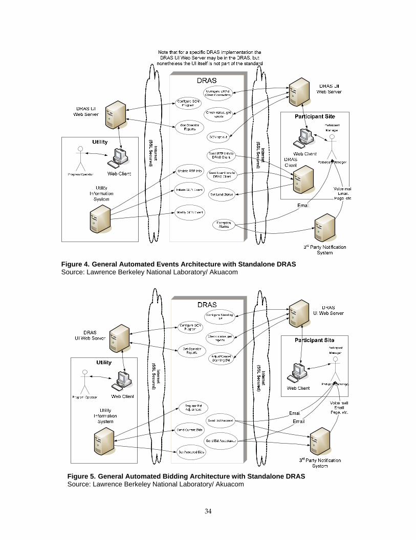
Figure 4. General Automated Events Architecture with Standalone DRAS Source: Lawrence Berkeley National Laboratory/ Akuacom
Figure 5. General Automated Bidding Architecture with Standalone DRAS Source: Lawrence Berkeley National Laboratory/ Akuacom
34

6.2. General Requirements
In analyzing various use cases and the architectures in the previous section, it is possible
to group the various functional requirements as shown in Figure 6.
DRAS
Utility/ISO FunctionsDRAS Client Functions
Utility/ISO - Handling DR Events
Initiate GEN Event
Modify GEN EventUpdate RTP Info
Request BidAdjustment
Participant – Submitting Feedback
Set Load Status
DRAS Client - Receive DR Event Information
Send Event Info toDRAS Client
Send RTP Info toDRAS Client
Participant – Opting Out of DR Events
GEN opt out
Utility/ISO – Configure DRAS
Configure GENProgram
Utility/ISO – Monitor DRAS Related Activities
Get OperatorReports
Operator Notifications
Send Bid RequestSend Bid AcceptanceException Alarms
Participant –Configure DRAS
Configure DRASClient Connection
Participant – Automated Bidding
Adjust/CancelStanding Bid
Configure StandingBid
Participant – Monitor DRAS Related Activities
Check status, getreports
Utility/ISO – Automated Bidding
Send Current Bids Set Accepted Bids
Participant Functions
Figure 6. Use Case References to Functional Specification Source: Lawrence Berkeley National Laboratory/ Akuacom
The interface functions supported by the DRAS can be classified into three groups:
Utility and ISO functions
Participant functions
DRAS Client functions
This classification reflects the role of the DRAS as an integration point between the
utility or ISO and the participants and the DRAS Clients. Because the DRAS may not be
a standalone entity, but instead may be integrated with a utility’s IT infrastructure, it is
not a requirement that the DRAS support those functions tagged as utility or ISO
functions. In the case where the DRAS is not integrated with the utility IT infrastructure
35

and supplied as a standalone entity, then it should support the interfaces tagged as
utility or ISO.
Furthermore, a particular implementation of the DRAS may contain a Web server that is
responsible for serving up a Web‐based user interface (UI) to the participant operators.
In this scenario it is not a requirement that the participant functions be made available
for third parties to implement their own Web‐based UI and therefore the methods
specified as part of the participant interface need not exist. Instead the functions
normally provided by the participant interface will be provided by some sort of UI or
tool that is integrated with the DRAS and therefore need not utilize the methods
specified in the participant interface. If it is a requirement that the DRAS allows third
parties to build Web‐based clients for participants then the methods described as part of
the participant interface must exist as specified below.
In any case, the DRAS must support the methods tagged as belonging to the DRAS
Client interface.
The participant, utility or ISO, and DRAS Client interfaces are further decomposed into
specific methods and covered in more detail below.
In addition to the functional descriptions given below, the data model entities used as
parameters for each of these methods are also described. The conceptual data models
developed are from the point of view of the utilities, participants, and DRAS Clients and
are depicted in the conceptual entity relationship diagram (ERD) in Section 6.4.1.
For the remainder of this document the term function and method are interchangeable
and take on their normal meaning, i.e. referring to a software interface construct that is
used to execute a certain well defined set of functionality.
6.3. Common Requirements
All DRAS functions must satisfy the following requirements:
They must all be implemented using some type of reliable communications,
meaning that it must be possible to determine if information exchanged as part
of executing the function was received correctly.
All functions must adhere to the minimum security policies specified in Section
10.
All functions must be implemented using industry standard Web services.
All functions must restrict access based upon a well documented set of security
roles.
36

6.3.1. Demand Response Automation Server User Accounts and Security Roles
For security reasons, each of the functions accessed through the interfaces of the DRAS
defined in this specification can only be accessed by users with an appropriate
authorization on the DRAS. Further details are described in DRAS security policies. In
addition, accounts that are created to allow access to functions on the DRAS have one or
more security roles. The following types of security roles are used:
DRAS Operator – DRAS operators are highly trusted individuals with wide
ranging access to all information and functions of the DRAS documented in this
specification including creating other users with their appropriate security roles.
DRAS operators cannot be created via any of the interfaces documented in this
specification.
Participant Manager – Participant managers have access to all the information
associated with a particular participant account. They are created by using the
functions described in Section 0.3. Within the context of this document a
participant manager may also be referred to as a “Participant Operator”.
DRAS Client – The DRAS Client represents the software agent for the machine to
machine communications between the DRAS and the participant facility. DRAS
Clients are created as part of the configuration process described in Section 0.2.
Utility and ISO Operator – Utility and ISO operators have access to all the utility
methods and functions in the DRAS. This process is beyond the scope of this
document.
DRAS Client Installer (Technical Coordinators) – These are the individuals that
are responsible for installing and testing DRAS Clients in the field. How these
accounts are created are beyond the scope of this document.
Participant manager and DRAS Client accounts are established as part of the
configuration of the DRAS as described in Section 0. The DRAS operator, utility
program operator, and DRAS Client installer accounts are managed by processes
that are outside the scope of this document.
6.3.2. Logs and Reports
The DRAS must track and log the items described in this section. In general each of the
items logged are accessible by the various operators. In addition the DRAS must
monitor exception conditions that result in so called alarms. In general, alarms result in
the notification of various operators as described in Section 6.3.3.
DRAS operators and utility program operators may access the logs and alarms of all the
transactions regardless of the participant while participant managers may only access
the logs and alarms associated with their transactions. Also no one should be permitted
to delete logs.
37

As a practical matter the DRAS cannot keep logs forever since their size will eventually
fill up available storage resources. It is therefore not a requirement that the DRAS keep
logs indefinitely. The process to specify the historical DRAS communications logs is
beyond the scope of this document. The various items that are logged by the DRAS are
detailed below.
The DRAS Client Communications State
The DRAS is required to track the communications state of each DRAS Client. A DRAS
Client may be in one of the following communications states:
Online – the DRAS Client is communicating properly.
Degraded (online with errors ‐ note that the threshold for this is implementation‐
specific)
Communications Failed.
Out of Service (provisioned offline for testing, maintenance, etc.)
As described by the functions in Section 0, the DRAS Client’s communication state can
be queried at any time.
All Transactions With the DRAS
The DRAS must log all invocations of functions as part of its normal operation. The
information recorded is specified by the TransactionLog entity as described in the data
model section. As described in Section 0 the DRAS Client’s transaction logs may be
queried at any time.
Exceptions and Alarm Conditions
The following alarms must be tracked by the DRAS.
DRAS Client communication going ON or OFF line.
In general alarms result in operator notifications as described in Section 6.3.3. In
addition alarms must be logged by the DRAS so that they may be queried using the
functions described in Section 0.
6.3.3. Operator Notifications
The DRAS may send notifications to various human operators under a variety of
circumstances. In order to notify the human operators the DRAS must support email
notification and may support interfacing to third party notification systems. Third party
notification systems include pagers, voice mail, text messages, etc. The process of how
the DRAS interfaces to third party notification systems is beyond the scope of this
document.
38

In general, participant operators and utility program operators may be sent notifications
by the DRAS. The email contact information for a participant operator is specified in the
ParticipantAccount object for that participant as described in the data model section. The
utility program operator’s email contact information is specified when their account is
set up by the DRAS operator. The process to specify the format of the email messages
that are sent to the various operators is beyond the scope of this document.
The DRAS must send the following notifications:
DRAS Client ON or OFF line. The DRAS must track when a DRAS Client goes
ON or OFF line and when it does it must send an email notification to the
following operators:
o The participant operator(s) who manages that DRAS Client if so configured
to receive notifications.
o The utility program operator who configured the participant account to
receive these notifications.
o All DRAS operators.
DR event initiated. When the utility or ISO issues a DR event or modifies an
existing DR event then a notification must be sent to all participant operators that
are associated with DRAS Clients that would normally receive that event. Note
that the program may require bidding by the participant in which case this
notification may be a request for a bid.
Participant bids accepted or rejected. When a participant’s bids have been
accepted or rejected the participant operator must be notified.
6.3.4. Testing
The DRAS must support the testing of DR event configurations and communications
with DRAS Clients. It must support the following types of tests:
End to end testing of DR events. It supports this by allowing the utility or ISO to
initiate so called test events. These are treated like any other DR events by the
DRAS including sending the DR event information to DRAS Clients. The only
difference is that there is a field in the DR event information that signifies that
the event is a test event. When the DRAS Client receives test events it may
choose to deal with it in whatever fashion is appropriate for the test scenario in
the facility, including ignoring it.
DRAS Client testing. There is a way for DRAS Client installers to take a DRAS
Client off line in the DRAS and send it test messages. The DRAS Client installer
has the ability to set various state variables that are used by DRAS Clients so that
they can be manually controlled. See Section 7.3.6.
6.4. Introduction to Data Entities Used By Interface Functions
39

This section gives a brief description of the various data entities used for information
exchange via the various functions described in this specification. This section is only
meant to give a brief introduction and conceptual overview of the various data entities.
The conceptual data model represents the various data elements that are part of the
DRAS operation as they are viewed from the point of view of the utility or ISO and the
participants. It is not intended to represent a specific database schema that is
implemented in the DRAS but rather represent the various data elements that are used
by, the utility or ISO, participants, and DRAS Clients when they interface to the DRAS.
The conceptual data model is represented by several Entity‐Relationship (ER) diagrams.
Each diagram is a collection of entities and the relationships between them. Each Entity
represents a basic data element with the following characteristics:
Name of the data entity
Primary Key of the entity (“PK”). This is an identifier that represents how the
entity may be referenced by other entities.
Data elements or attributes. These are the various fields of the entity.
References to other entities. Often a particular entity will refer to another entity,
represented by the foreign key (“FK”). These foreign keys are the primary keys
of the entities that they refer to.
Key to Interface Function Figures
Each discussion in this section focuses on those entities that are shaded in the
corresponding reference figures. Un‐shaded entities have been defined elsewhere as part
of another process. Furthermore, attributes in bold are required while the others are
optional. Arrows are used when one entity refers to another. The text label on the arrow
notes the type of relationship between the two entities. The number sequence associated
with the arrow specifies how many of the entities are referred to in the relationship, for
example:
1..* means at least one but possibly many (one to many)
1 means exactly one (one to one)
* means zero to many
Note that while this section is relatively descriptive in nature, the name given for each of
the entities and their accompanying fields and attributes match the names given in
Section 0, which contains a more detailed description of the schemas for each of the
entities presented here.
6.4.1. Data Entities in Support of Utility and ISO Use Case Actions
The entities in this section are specifically used by the various operations in support of
the utility or ISO functions. As such, they are organized according to the various
functions that may be performed.
40

Utility Issues DR Event
These are the entities used when the Utility or ISO initiates a DR event. In particular the
UtilityDREvent entity is used to specify all the information associated with a DR event
and contains the following general attributes:
eventIdentifier – This is a globally unique ID that is specified by the utility or ISO
when the DR event is issued. It is subsequently used to associate and retrieve
information related to a particular DR event.
programName – This is an identifier that specifies which DR program the DR
event is being issued for.
eventModNumber – This is a sub identifier to the event identifier and is used
specifically to determine when changes have been made to the DR event
information since the last time it was issued. For example, the very first time a
DR event is initiated by the utility or ISO, this has a number of 0 and will
continue to have a value of 0 for each and every subsequent transmission unless
the DR event is subsequently modified by the utility or ISO. At that time this
number is increased to the next version number, indicating the original event
was modified.
utilityITName – This is an optional field which is the name and/or version
number of the utility IT system that initiated the DR event.
Destinations – This is a list of identifiers that specifies who is to receive the DR
event. Note that it can be any of the following:
o Explicit Participant Account User ID(s) (uid)
o Group identifiers
o DRAS Client location specifications
eventTiming – Various timing parameters for the event, including:
o notificationTime – This is the time at which the participants should be
notified of the DR event.
o startTime – This is the date and time that the DR event becomes active.
o endTime – This is the date and time that the DR event ends.
biddingInformation – If a program supports bidding by the participants then the
following fields are also included.
o openingTime – This is the time at which the participants may start placing
bids.
o closingTime – This is the time at which the bidding will close and is the
deadline for which the utility may receive the bids from the DRAS.
Event Information – This is the information associated with the DR event and is a
list of EventInfoInstance entity as described below.
41
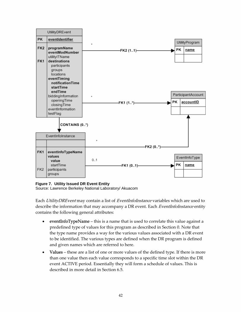
Figure 7. Utility Issued DR Event Entity Source: Lawrence Berkeley National Laboratory/ Akuacom
Each UtilityDREvent may contain a list of EventInfoInstance variables which are used to
describe the information that may accompany a DR event. Each EventInfoInstance entity
contains the following general attributes:
eventInfoTypeName – this is a name that is used to correlate this value against a
predefined type of values for this program as described in Section 0. Note that
the type name provides a way for the various values associated with a DR event
to be identified. The various types are defined when the DR program is defined
and given names which are referred to here.
Values – these are a list of one or more values of the defined type. If there is more
than one value then each value corresponds to a specific time slot within the DR
event ACTIVE period. Essentially they will form a schedule of values. This is
described in more detail in Section 6.5.
42

Participants – this is a list of participants for which these values apply. It allows
the information associated with a DR event to be applied to specific participants.
Groups – this is a list of groups for which these values apply. Since participants
may belong to a group, groups are another way of specifying which participants
are to receive the information.
As can be seen by the diagram it is assumed that the following entities exist before an
UtilityDREvent is created that refer to them:
UtilityProgram
ParticipantAccount
EventInfoType
Utility Configuration of DRAS
When the utility or ISO configures the DRAS, it uses the entities shown in Figure 8.
The UtilityProgram entity represents all the information associated with a DR program
that is created by a utility or ISO. Each program has a set of attributes that describe how
the program is managed and run from the point of view of the DRAS and participants.
The attributes include the following type of information:
A name.
A ProgramConstraint entity in the form of time and date attributes which specify
when a DR event can be issued.
List of participants that participate in the program.
Parameters that control how bidding is performed by a participant as part of the
program.
Specifications for the type of information that can be associated with a DR event
in the form of EventInfoType entities.
A priority for the program in relation to other programs.
The EventInfoType entities are part of the UtilityProgram entities and are used to
specify the type of information that may be associated with a DR event when one is
issued. Examples of this kind of information may include things like real time prices,
shed or shift levels, etc. An EventInfoType contains the following general attributes.
A name.
A specification for the data type of the information.
A specification for constraints on the allowable values such as minimum and
maximum values.
A specification for a schedule if the values may change according to some fixed
schedule during the course of a DR event. An example might be prices where
43

EventInfoType entities are described in more detail in Section 6.5.
The ParticipantAccount entity contains all the attributes associated with a participant. It
contains the following types of information:
Participant name.
Access credentials (e.g. user name and password) for accessing the functions of
the DRAS. Note that a ParticipantAccount may have multiple DRAS Clients
associated with their account and each of the DRAS Clients will have access
credentials that are distinct and separate from the access credentials specified
here.
Groups that the participant may belong to. Groups are a way to refer to more
than one participant for various operations of the DRAS.
Programs and dynamic pricing activities that the participants may participate in.
ProgramConstraint variables associated with how the participant may
participate in a Program.
DRASClient entities that describe the DRAS Clients that the participant will use
to communicate with the DRAS.
Bidding information for any standing bid that the participant may set up.
Contact information for the DRAS to send notifications to the participant
operators.
The ParticipantAccount entity is created by the utility and various fields may be edited
by the participant. See Section 8.5 for a more detailed description of the
ParticipantAccount entity.
44

Figure 8. Utility Configuration Entities Source: Lawrence Berkeley National Laboratory/ Akuacom
45

Utility Manages Bids
When a participant submits bids to participate in a DR event, those bids are sent to the
utility or ISO. The data entities used to represent the bids are described in Section 0.
Utility gets Logs and Alarms
The DRAS is required to maintain logs and track alarms that record a variety of
activities associated with the DRAS. The data entities used to represent these activities
are show in the conceptual ER diagrams in Figure 9. Each entity contains enough
information so that it is possible to determine who, when, and what was involved. These
are described in more detail in Section 8.7.
Figure 9. Utility Logs and Client Alarms Source: Lawrence Berkeley National Laboratory/ Akuacom
46

6.4.2. Data Entities in Support of Participant Operator Functions
Participant Configuration
The conceptual ER diagram, Figure 10, shows the various entities that may be created
and configured by the participant. They represent the pieces of data that are used for
various operations involving the participant.
The utility or ISO creates a ParticipantAccount. The participant may edit only a subset of
the attributes associated with this entity. See Section 8.5 for a detailed description.
The participant may define a number of ProgramConstraints. Each of these is associated
with a particular program and defines limitations of how a participant may participate
in that program. Note that the ProgramConstraints which are defined for a particular
participant are intended to customize the various schedule attributes of how a
participant participates in a program and are distinct from the ProgramConstraints that
a utility may define globally for a program. The ProgramConstraints for the participant
supersede the ProgramConstraints that are defined for the program as a whole. See
Sections 0 and 8.4 for a detailed description of this entity.
A ParticipantAccount may have a number of Bid entities that represent standing bids
associated with specific programs that may require bidding. See Sections 6.6 and 8.11 for
a more detailed description of this entity.
A ParticipantAccount may also define a number of DRASClient entities. A DRASClient
entity represents the information associated with a DRAS Client and includes the
following types of information:
Type of DRAS Client–Simple or Smart type.
Programs that the DRAS Client may participate in.
ProgramConstraints that define how the DRAS Client will participate in
programs.
Communications parameters that define how the DRAS Client communicates
with the DRAS.
Location information.
ResponseSchedule entities for the various programs and dynamic pricing that
the DRAS Client may participate in if the DRAS Client is a Simple type.
See Section 8.10 for a more detailed description of a DRASClient entity. See Section 0 for
a more detailed description of Simple and Smart DRAS Clients.
The ResponseSchedule entities are used by Simple DRAS Clients and represent the
translation of the DR event information into simple levels and status. As shown in
Figure 10 a ResponseSchedule entity is a collection of OperationStates. See Sections 6.5
and 8.3 for a more detailed description.
47
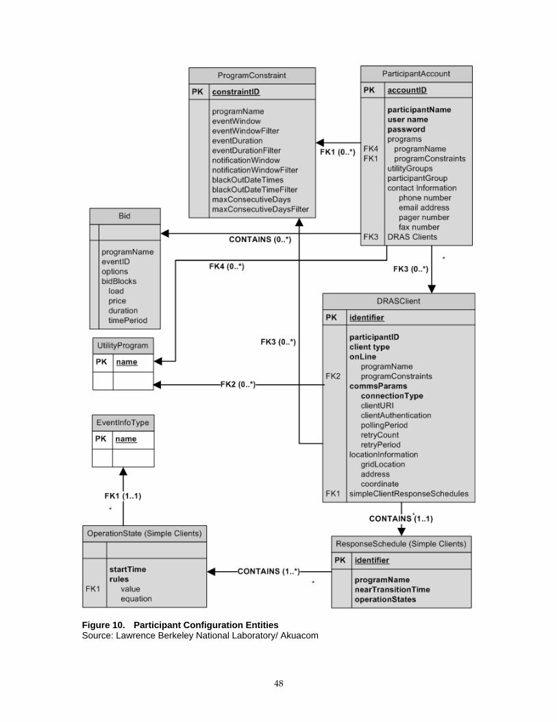
Figure 10. Participant Configuration Entities Source: Lawrence Berkeley National Laboratory/ Akuacom
48

Participant Operator Submit Bids
When a DR event is issued by the utility or ISO requiring bidding, the participant uses
the Bid entity to submit those bids. The Bid entity is described in more detail in Section
8.11.
Figure 11. Participant Submit Bid Entity Source: Lawrence Berkeley National Laboratory/ Akuacom
Participant Operator Opt-Out State of DR Events
A participant may choose to opt‐out or override participating in DR events. The
participant does this by using the OptOutState entity to set up one or more conditions
within the DRAS that define when the participant will not participate in a DR event. The
OptOutState may have the following attributes:
Which DR programs the conditions apply to. If not specified, it defaults to all
programs.
Which DRAS Clients the conditions apply to. If not specified, it defaults to all
DRAS Clients.
Which DR event the conditions apply to. If not specified, it defaults to all DR
events.
A schedule which defines when the conditions apply.
49

Note that there can be more than one such set of conditions established by the
participant. See Section 8.6.
Figure 12. Participant Opt-Out Entities Source: Lawrence Berkeley National Laboratory/ Akuacom
Participant Operator Submits Feedback
The participant may use the ParticipantFeedback entity to notify the DRAS about
various conditions or information related to the participant. Examples include demand
data and how the participant is responding to a DR event. The Feedback information can
be read by the utility or ISO. See Section 8.8 for a more detailed description of the
ParticipantFeedback entity. Note that ParticipantFeedback may be submitted by various
roles within the system both human and machine. This entity would be used by all such
transactions to submit the feedback.
50

Figure 13. Participant Feedback Entities Source: Lawrence Berkeley National Laboratory/ Akuacom
Participant Operator Gets Logs and Alarms
The DRAS is required to maintain logs and track alarms that record a variety of
activities associated with the DRAS. The data entities used to represent these activities
are show in the conceptual ER diagrams in Figure 14 (repeated here for reference; Figure
14 is the same as Figure 9). Each entity contains enough information so that it is possible
to determine who, when, and what was involved in a DR event. These are described in
more detail in Section 8.7. The participant operator is only allowed to access logs for
which they have access rights, i.e. those items related to their ParticpantAccounts.
51

Transactions Logs
user nameroledate/time stampmethod namedescriptionresult
DRASClientAlarms
date/time stampDRAS Client IDDescriptionstatus
Figure 14. Client Alarms and Utility Logs Source: Lawrence Berkeley National Laboratory/ Akuacom
6.4.3. Data Entities in Support of Demand Response Automation Server Client Functions
As shown in the conceptual ER diagram, Figure 15, the interaction between the DRAS
and the DRAS Client involves two entities. The first is the EventState which is a
representation of the “state” that the DRAS Client may be in with respect to a DR event.
This entity is sent from the DRAS to the DRAS Client. The second is a confirmation
message (EventStateConfirmation) or acknowledgement that the DRAS Client sends to
the DRAS to notify the DRAS that it has received an EventState message. Note that most
of the fields in the EventStateConfirmation are simply copies of the fields from the
EventState message that it is replying to. Note that the DRAS Name field provides a
means for DRAS Clients to interact with more than one DRAS even though each DRAS
may have no knowledge or interdependencies between them.
The EventState contains all the relevant information that describes a specific DR event to
the DRAS Client. The same EventState entity is used for both Simple and Smart DRAS
Client types. The EventState is described in more detail in Sections 6.5.3 and 8.12. Note
that specific Web service interfaces may have a slightly different schema for the
EventState as described in Section 9.3.
52
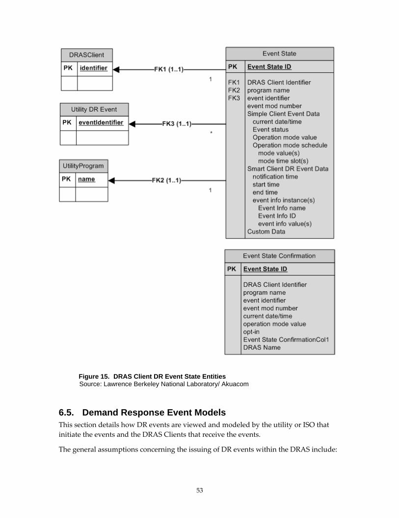
Figure 15. DRAS Client DR Event State Entities Source: Lawrence Berkeley National Laboratory/ Akuacom
6.5. Demand Response Event Models This section details how DR events are viewed and modeled by the utility or ISO that
initiate the events and the DRAS Clients that receive the events.
The general assumptions concerning the issuing of DR events within the DRAS include:
53

The DRAS is assumed to be managed by a single business entity. While there
may be multiple utility or ISO operator accounts, there is only a single business
entity that is responsible for issuing DR events. This means that if there is a
DRAS that is managed by a third party there cannot be more than one utility or
ISO that can issue DR events through that DRAS. This assumption is designed to
avoid conflicts between events and other issues that should be resolved by the
entity that is issuing the DR events.
Only one event for a specific DRAS Client may be active at any time. See below
for a more formal definition of an “active” event. There may be multiple events
issued and pending, but only one of them will be active.
DR programs may have a priority associated with them.
DR events with overlapping active periods may be issued, but only if they are
from different programs and dynamic pricing and only if the programs have a
priority associated with them. DR events for programs and dynamic pricing with
higher priorities supersede the events of programs and dynamic pricing with
lower priorities. If two programs and dynamic pricing with overlapping events
have the same priority then the program whose event was activated first takes
priority.
6.5.1. Utility or ISO View of a Demand Response Event
When the utility or ISO initiates a DR event it uses an UtilityDREvent entity which
contains the following general attributes:
The DR program the event is for.
Time and date parameters concerning when the event will take place.
Time and date parameters concerning when participants should be notified of
the upcoming event.
Who and/or where to send the DR event information.
Information associated with the event (EventInfo). This is program specific
information that is related to the event, e.g. RTP or shed or shift level.
Demand Response Event Time Parameters and States
Figure 16 shows the different time parameters associated with DR event states. The
participants are notified of an upcoming event at the Issue Time (A).The time period
between the Event Start Time (B) and the Event End Time (C) is known as the
“ACTIVE” state for the DR event. The “ACTIVE” state for the DR event is the only state
or time during which the EventInfo is valid. The time period from the Issue Time (A) till
the Start Time (B) is the “PENDING” state of the DR event. The “PENDING” state of the
DR event is the time during which the DR event is pending, “IDLE” periods, with
respect to this DR event, are the times before the Issue Time (A) and after the End Time
(C). Event Information (D) is the information associated with a DR event ‐ See Section 0
54

for what information is included. Another way to look at state transitions is provided in
Figure 17; this figure is described in detail in Section 6.5.3.4.
Figure 16. DR Event Model (Utility or ISO View) Source: Lawrence Berkeley National Laboratory/ Akuacom
Figure 17. State Transition Diagram Source: Lawrence Berkeley National Laboratory/ Akuacom
55

DR Event Information
DR programs and dynamic pricing are typically designed to use a variety of information
to cause reactions by participants to DR events that are issued by the utility or ISO. In
some cases prices are used to trigger responses to the DR events while in other case it
might be a shed or shift level. In general, there can be a wide range of different types of
information associated with a DR event depending upon how the DR program was
designed. Therefore, the data models used to describe the information associated with
DR events are designed to accommodate the wide range of information that may be
associated with a DR event. This information is represented by EventInfo entities.
When a program is defined within the DRAS, there are specifications associated with the
program that define what type of information may be associated with a DR event when
one is issued for that program. Each type specification for an EventInfo is referred to as
an EventInfoType. A program may be defined that allows for multiple different types to
be associated with a program. Each EventInfoType contains the following attributes and
elements.
EventInfoType
Name – this is the name of the type of event in use. Analogous to a variable
name.
typeID – this identifies the type of information and may take on one of the
following values:
o PRICE_ABSOLUTE – Price number, i.e. $0.25
o PRICE_RELATIVE – Change in price, i.e. ‐$0.05
o PRICE_MULTIPLE – Multiple of current price, i.e. 1.5
o LOAD_LEVEL – Amount of load based on an enumeration, i.e. moderate,
high, etc.
o LOAD_AMOUNT – Fixed amount of load to shed or shift, i.e. 5 MW
o LOAD_PERCENTAGE – Percentage of load to shed or shift, i.e. 10%
o GRID_RELIABILITY – Number from 0–100 signifying the reliability of the
grid. 100 signifies the highest level of reliability while 0 is the lowest.
scheduleType – This specifies how a schedule may be associated with the DR
event information is defined and may take on the following values:
o NONE – There is no schedule and thus EventInfo does not change values
during the entire DR event ACTIVE state.
o DYNAMIC–The time schedule is not fixed during configuration, but can be
set when the DR event is issued.
o STATIC–The schedule is fixed when the DR program is configured within
the DRAS
56

Schedule – If the scheduleType is STATIC, this is the configured schedule. A
schedule is a sequence of time slots that are valid over the entire ACTIVE period
of a DR event.
enumerations – This is a list that defines a fixed set of values that the EventInfo
instance may take. If defined, the EventInfo instance is an enumeration and can
take on any of the values in the list. If left undefined, the EventInfo instance can
take on any contiguous value between the minValue and maxValue.
minValue – Minimum possible value of an EventInfo instance.
maxValue – Maximum possible value of an EventInfo instance.
Note that when a DR event is issued the EventInfo instances that are associated with the
DR event may take on values that change according to some schedule during the
ACTIVE state of the DR event. Also note that the schedule that defines when these
values change may be defined as part of the definition of an EventInfoType or it may be
defined when the DR event is issued. See Section 8.9 for a detailed description of the
EventInfoType schema.
How the EventInfoTypes are used by the DRAS Clients varies depending upon whether
it is a Simple or Smart DRAS Client. See Section 6.5.3 for a more detailed description of
how DRAS Clients view DR events and how they use the EventInfo instances and types
of information.
6.5.2. Propagation of Demand Response Events by the Demand Response Automation Server
The propagation of DR events from the utility or ISO to the DRAS Clients is controlled
by a number of data entities and parameters that are configured by the utility or ISO
and/or the participant. In general there exists the following hierarchy:
Programs and dynamic pricing (DR events are issued as part of a program)
- Participants which belong to programs
o DRAS Clients which belong to participants and programs
When a DR event (UtilityDREvent) is issued there is a so called “destination” attribute
which specifies which DRAS Clients will ultimately receive the DR event information.
The destination specification may take on one or more of the following attributes:
Participants – this is a list of participants that reference ParticpantAccount
entities that should receive the DR event. If a participant is specified then it is
assumed that all the DRAS Clients that belong to that participant will receive the
DR event. The exceptions are those DRAS Clients that explicitly do not belong to
the program that the DR event was issued for.
Groups – Participants can belong to a Utility Group. Utility Groups are used as a
shorthand way of specifying more than one participant. Specifying a Utility
57

Group is functionally equivalent to specifying each individual participant that
belongs to that group.
DRAS Clients – this is simply an explicit list of the specific DRAS Clients that
should receive the DR event.
Location – Each of the DRAS Clients may have a location attribute that is used to
specify where geographically on the utility or ISO grid that a DRAS Client is
located. That location attribute can be used as a means to specify which DRAS
Clients should receive a DR event.
Each of the attributes above may be used to define a set of DRAS Clients. For example
each participant may have one or more DRAS Clients associated with their account on
the DRAS. Therefore, if a particular ParticipantAccount is specified then it is referring to
all the DRAS Clients associated with that account. Since each of the attributes above
represent a different criteria for specifying a set of DRAS Clients they can be used in
conjunction with each other to specify a specific set of DRAS Clients by logically taking
the intersection of all the sets of DRAS Clients that are specified by each attribute.
It should be noted that these propagation rules are a form of business logic within the
DRAS and must be implemented by each DRAS that complies with this OpenADR
specification. The various parameters and assumptions that the DRAS must follow are
shown in Figure 18.
58

Figure 18. Relevant Attributes and Structures for Event Propagation Source: Lawrence Berkeley National Laboratory/ Akuacom
Demand Response Event Propagation Examples
Figures 19 through 26 shows how a DR event must be propagated by the DRAS based
upon various destination parameters. Figure 19 provides the sample configuration that
will be used as a basis for Figures 20 through 26, which provide examples of how the
same configuration may be used to propagate DR events in different ways depending
upon the destination specification for a DR event. The bold arrows in each diagram
illustrate where the DR event is logically being propagated, including:
59

DR Event Propagation for program P2–All Participant Accounts (Figure 20)
DR Event Propagation for Program P2–Specific Participant Accounts A3, A4 (
Figure 21)
DR Event Propagation for Program P1–Specific Participant Account A1 (Figure
22)
DR Event Propagation for Program P2–Groups G2, G4 (Figure 23)
DR Event Propagation for Program P2–Specific DRAS Clients C1, C4, C5 (Figure
24)
DR Event Propagation for Program P2–Specific Locations L1, L3 (Figure 25)
DR Event Propagation for Program P2–Groups G2 and Participants A4 Specified
(Figure 26)
Participant Acct – A1- Programs: P1, P2- Groups: G1, G2
DR Event- Program P1- Destinations
- Participants: none- Groups: none- DRAS Client: none- Location: none
DRAS Client DRAS Client DRAS Client DRAS Client DRAS Client
DRAS Client – C1- Programs: ALL- Location: L1, L2
DRAS Client – C2- Programs: P1- Location: L3
DRAS Client – C3- Programs: ALL- Location: L1
DRAS Client – C4- Programs: P2- Location: L2
DRAS Client – C5- Programs: ALL- Location: L3
Participant Acct – A2- Programs: P1,P2,P3- Groups: G2, G3
Participant Acct – A3- Programs: P2- Groups: G3
Participant Acct – A4- Programs: P2, P3- Groups: G3, G4
Figure 19. Sample Configuration - Participant Accounts and DRAS Clients Source: Lawrence Berkeley National Laboratory/ Akuacom
60

Figure 20. DR Event Propagation for Program P2–All Participant Accounts Source: Lawrence Berkeley National Laboratory/ Akuacom
61

Figure 21. DR Event Propagation for Program P2–Specific Participant Accounts A3, A4 Source: Lawrence Berkeley National Laboratory/ Akuacom
62

Figure 22. DR Event Propagation for Program P1–Specific Participant Account A1 Source: Lawrence Berkeley National Laboratory/ Akuacom
63

Figure 23. DR Event Propagation for Program P2–Groups G2, G4 Source: Lawrence Berkeley National Laboratory/ Akuacom
64

Figure 24. DR Event Propagation for Program P2–Specific DRAS Clients C1, C4, C5 Source: Lawrence Berkeley National Laboratory/ Akuacom
65

Figure 25. DR Event Propagation for Program P2–Specific Locations L1, L3 Source: Lawrence Berkeley National Laboratory/ Akuacom
66
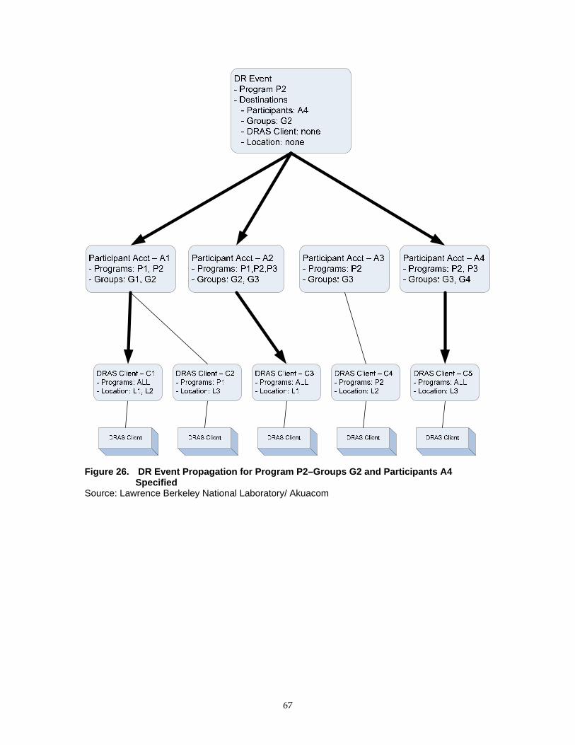
Figure 26. DR Event Propagation for Program P2–Groups G2 and Participants A4 Specified
Source: Lawrence Berkeley National Laboratory/ Akuacom
67

Program Constraints
This section describes how so called program constraints effect the propagation of DR
events. Program constraints are represented by the ProgramConstraint entity. The
ProgramConstraint entity represents a set of parameters that constrain various time and
date parameters associated with a particular DR event. See Sections 0 and 8.4 for a more
detailed discussion of the ProgramConstraint entity. When a DR event is issued the
DRAS compares the parameters of the DR event against various sets of program
constraints as the DR event is propagated. Figure 27 shows the different points at which
ProgramConstraint variables maybe applied to a DR event as it is propagated to a
specific DRAS Client.
First the DRAS compares the DR program against ProgramConstraint variables that are
configured to be part of the program. In addition to ProgramConstraint variables
associated with a program as a whole, it is possible for the utility or ISO to create
ProgramConstraint variables that are applicable to a single DR event. If
ProgramConstraint variables exist for a single DR event then they will supersede any
ProgramConstraint variables that may exist for the program as a whole. No comparisons
are made if a program or a DR event does not have ProgramConstraint variables.
Next the DR event is compared against the ProgramConstraint variables for every
participant that is deemed to receive the DR event. Each participant may or may not
associate a set of ProgramConstraint variables with their ParticipantAccount that are
related to a particular program. If there are no ProgramConstraint variables for the
participant and program in question then no comparison is done.
Next the DR event is compared against ProgramConstraint variables for every DRAS
Client that is deemed to receive the DR event as described above. Each DRAS Client
may or may not associate a set of ProgramConstraint variables that are related to a
particular program. If there are no ProgramConstraint variables for the DRAS Client and
program in question then no comparison is done.
The attributes of the ProgramConstraint variables at successive levels must not be in
conflict with the attributes at the level above it. What this means is that attributes of the
ProgramConstraint variables of a DRAS Client must not be in conflict with attributes of
the ProgramConstraint variables of a participant which in turn must not be in conflict
with attributes of the ResponseSchedule for a program as a whole. Constraints are
considered to be in conflict if it is impossible for any DR event to satisfy any of the
constraints.
68
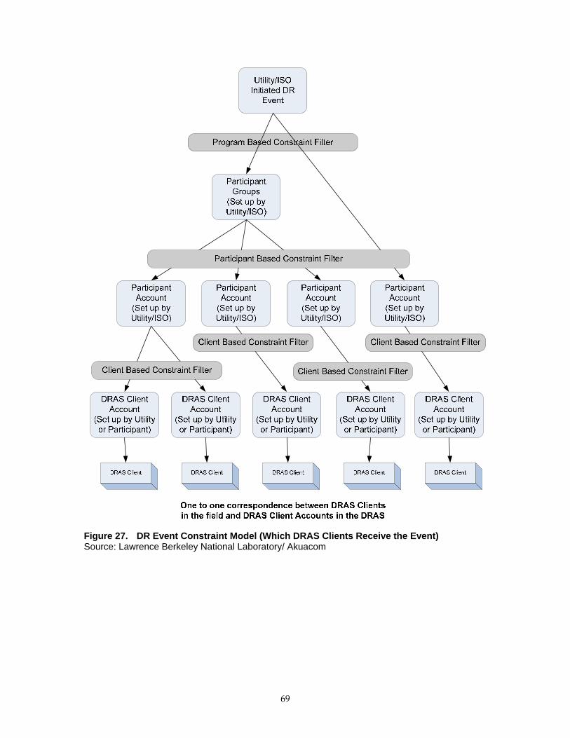
Figure 27. DR Event Constraint Model (Which DRAS Clients Receive the Event) Source: Lawrence Berkeley National Laboratory/ Akuacom
69

Figure 28 shows the comparison process of the DR event as it progresses through the DR
event propagation process. The various parameters compared against the issued DR
event include:
Event window – This is the valid time window during the day that a DR event
can occur.
Event duration – This is the maximum event duration for a DR event.
Notification window – This is the minimum and maximum time before an event
that a participant can be notified of a DR event.
Blackout dates – These are dates during which DR events can not be issued.
Valid dates – These are the dual of the blackout dates and represent the ONLY
dates during which a DR event may be issued.
Max consecutive days – This is the maximum consecutive days that a DR event
can be issued.
Each of these parameters is optional, but if they are defined then they are compared to
the following DR event parameters:
Notification time
Start time
End time
Figure 28. Program Constraints and Filters Source: Lawrence Berkeley National Laboratory/ Akuacom
The process of comparison checks the parameters of the DR event against the relevant
parameters of the ProgramConstraint entity. If there is a mismatch then the DRAS must
take an action which is further specified in the ProgramConstraint entity. Each
parameter in the ProgramConstraint entity has a corresponding attribute which specifies
how the DRAS will respond to mismatches between the DR event and the
ProgramConstraint entity. The possible actions are the following:
ACCEPT – simply accept the issued DR event regardless of any conflicts.
70

REJECT – reject any DR events that conflict with configured constraints.
FORCE – regardless of what the issued DR events parameters are (even if there is
no conflict) force them to be the parameters that were configured in the
ProgramConstraint entity.
RESTRICT – modify the DR event parameters so that they legally fall within the
bounds of the attributes in the ProgramConstraint entity.
Each of these are referred to as “filter constraints” since they specify how the DR event
may be filtered by the DRAS.
Figures 28 through 30 illustrate the various actions taken when there are mismatches
between the DR event and the attribute of the ProgramConstraint variables. Each
diagram represents a different schedule related attribute of the DR event and how that
specific attribute is handled when there is a conflict between the DR event that is issued
and some ProgramConstraint that it is being compared against.
Figure 29. DR Event Window Depending Upon Filter Constraints Source: Lawrence Berkeley National Laboratory/ Akuacom
71

Figure 30. DR Event Notification Time Depending Upon Filter Constraints Source: Lawrence Berkeley National Laboratory/ Akuacom
Figure 31. DR Event Duration Depending Upon Duration Constraints Source: Lawrence Berkeley National Laboratory/ Akuacom
6.5.3. Demand Response Automation Server Client View of Demand Response Events
This section presents the DR event model used by the DRAS Client.
72

When a DR event is issued by the utility or ISO, information concerning the DR event is
sent to the various DRAS Clients at the appropriate time depending upon the state of the
DR event and the state of the DRAS Client. The type of information sent from the DRAS
to the DRAS Client concerning the DR event includes the following:
DRAS Client identifier
Program name associated with the DR event
Identifier for the DR event that was issued by the utility or ISO
Transaction identifier for the DR event message. Used to identify specific DR
event messages.
Flag to signify if the DR event is a test message
Flag to signify whether the DRAS Client is on or off line
Simple DRAS Client data – this data is intended to be used by Simple DRAS
Clients
o Event status
o Operation mode value
o Current time
o Operation mode schedule
Smart DRAS Client data – this information is intended to be used by Smart
DRAS Clients.
o Event notification time
o Event start time
o Event end time
o Event information (EventInfo instances)
Custom data – this is a placeholder for information that is intended to be used for
purposes beyond the scope of this document. It may be used to send proprietary
commands or information to a DRAS Client.
This collection of information is represented by the EventState entity and represents the
state that a DRAS Client is in with respect to a particular DR event. See Section 8.12 for a
more detailed description of the EventState data model and schema.
This rest of this section describes in more detail how the EventState entity is exchanged
with the DRAS Client.
Modes of Interaction (PUSH Versus PULL)
The DRAS and the DRAS Client may exchange EventState information using two
different modes of interaction ‐ PUSH and PULL.
In the PUSH mode (Figure 32), the EventState information is “pushed” from the DRAS
to the DRAS Client. This means that the communication of the EventState information is
73

initiated by the DRAS. In terms of Web services this means that that DRAS Client is the
Web server and the DRAS is the Web client.
Figure 32. PUSH Model Sequence Diagram Source: Lawrence Berkeley National Laboratory/ Akuacom
Note that in the PUSH model of information exchange the EventState is transmitted to
the DRAS Client whenever the state of the DR event that is being monitored by the
DRAS changes. The various states of the EventState are discussed in more detail below.
In the PULL mode ( Figure 33), the EventState information is “pulled” from the DRAS
by the DRAS Client. This means that the communication of the EventState information is
initiated by the DRAS Client. In other words, the DRAS Client polls the DRAS for the
EventState information. In terms of Web services this means that the DRAS is the Web
server and the DRAS Client is the Web client. In the PULL model of information
exchange the EventState may be requested by the DRAS Client at any time.
Figure 33. PULL Model Sequence Diagram Source: Lawrence Berkeley National Laboratory/ Akuacom
74

Note that in both cases the DRAS Client sends a confirmation message to the DRAS
upon receipt of the EventState information. This confirmation message is intended to
give an additional level of confirmation beyond the reliable communications used for
the Web services interface and to allow the DRAS Client to give additional information
related to how it intends to respond to the DR event. More information concerning the
details of the confirmation message data model can be found in 8.12.
The DRAS must use the EventStateConfimation message as a means to confirm that the
DRAS Client has received the EventState information. If an EventStateConfirmation
message is not received within some time out period then the DRAS must assume that
the EventState message was not received by the DRAS Client.
The DRAS must support two‐way communications for both the PUSH and the PULL
model of interaction, but the DRAS Client is only required to support one or the other.
Typically the PULL model may be used since the DRAS Client has more control over the
communications including the ability to more easily communicate through firewalls and
being network‐friendly. The PUSH method would typically be used in scenarios where
very low latency of the messages delivery is required when a state change occurs. The
specific situation of implementing PUSH versus PULL models is outside the scope of
this document.
Simple Versus Smart DRAS Clients
The DRAS supports two different types of DRAS Clients – Simple and Smart.
The Smart DRAS Client is assumed to be capable of dealing with all the EventInfo
information that may be associated with a DR event that is initiated by the utility or ISO.
It can parse all the EventInfo information and make decisions about how to respond to
that particular DR event information.
On the other hand there are many cases where a Simple DRAS client is needed. These
cases have simplified EMCS that are incapable of any sophisticated logic or the ability to
deal with the wide range of information types that may be associated with a DR event.
In these cases, the DRAS translates the EventInfo information associated with a DR
event into a much simpler form, known as a Simple DRAS Client.
The DRAS must be capable of dealing with both Smart and Simple DRAS Clients.
Details on both of these scenarios are described below.
DR Event Information
DR programs are typically designed to use a variety of information to cause reactions by
participants to DR events that are issued by the utility or ISO. In some cases prices are
used to trigger responses to the DR events while in other cases it might be a shed or shift
level. In general there can be a wide range of different types of information associated
with a DR event depending upon how the DR program was designed. Therefore, the
data models used to describe the information associated with DR events are designed to
75

accommodate the wide range of information that may be associated with a DR event.
This information is represented by EventInfoInstance entities.
When a program is defined within the DRAS there are specifications associated with the
program that define what type of information may be associated with a DR event when
one is issued for that program. Each type specification for an EventInfoInstance is
referred to as an EventInfoType. A program may be defined that allows for multiple
different types to be associated with a program. Each EventInfoType contains the
following attributes and elements:
EventInfoType
Name – This is the name of the type. Analogous to a variable name.
typeID – This identifies the type of information and may take on one of the
following values:
o PRICE_ABSOLUTE ‐ Price number, i.e. $0.25
o PRICE_RELATIVE ‐ Change in price, i.e. ‐$0.05
o PRICE_MULTIPLE ‐ Multiple of current price, i.e. 1.5
o LOAD_LEVEL ‐ Amount of load based on an enumeration, i.e. moderate,
high, etc.
o LOAD_AMOUNT ‐ Fixed amount of load to shed or shift, i.e. 5 MW
o LOAD_PERCENTAGE ‐ Percentage of load to shed or shift, i.e. 10%
o GRID_RELIABILITY ‐ Number signifying the reliability of the grid
scheduleType – This specifies how a schedule may be associated with the DR
Event information is defined and may take on the following values:
o NONE – There is no schedule and thus the EventInfo does not change values
during the entire DR event ACTIVE state.
o DYNAMIC – The time schedule is not fixed during configuration, but can be
set when the DR event is issued.
o STATIC – The schedule is fixed when the DR program is configured within
the DRAS
Schedule – If the scheduleType is STATIC then this is the configured schedule. A
schedule is a sequence of time slots that are valid over the entire ACTIVE period
of a DR event. Each time slot may take on a different value in the
EventInfoInstance
enumerations – This is a list that defines a fixed set of values that the EventInfo
instance may take. If defined, the EventInfoInstance is an enumeration and can
take on any of the values in the list. If left undefined, the EventInfo instance can
take on any contiguous value between the minValue and maxValue.
minValue – Minimum possible value of an EventInfoInstance.
maxValue – Maximum possible value of an EventInfoInstance.
76
Note that when a DR event is issued, the EventInfoInstance variables that are associated
with the DR event may take on values that change according to some schedule during
the ACTIVE state of the DR event. Also note that the schedule that defines when these
values change may be defined as part of the definition of an EventInfoType or it may be
defined when the DR event is issued. See Section 8.9 for a detailed description of the
EventInfoType schema.
Note that the DRAS Client never sees the EventInfoType definitions within the DRAS.
Nonetheless it is useful to understand their structure in order to understand how the
DRAS translates information from the various EventInfoInstance variables described
below into the simple levels used by a Simple DRAS Client.
The EventInfoType defines the type of information that is associated with a DR event
and are specified as part of a program. Thus when a DR event is actually initiated it
contains instances of the EventInfoType that were defined to belong to the program.
These instances are referred to as an EventInfoInstance and from the DRAS Clients point
of view are defined as follows.
EventInfoInstance
eventInfoName – This is the same as the name field in the corresponding
EventInfoType definition.
eventInfoTypeID – This is the type identifier of the data and takes on the value
defined in the typeID of the EventInfoType definition.
eventInfoValues – These are the actual values of the instances. There may be
more than one if there is a schedule of values.
See Section 8.12 for a detailed description of the EventInfoInstance schema, especially as
it applies to how the schedule of values is defined.
Smart DRAS Client Event Information
The EventState message sent to a DRAS Client contains the following set of fields:
Smart DRAS Client type data–this information is intended to be used by Smart
DRAS Client
o Event notification time
o Event start time
o Event end time
o Event information (EventInfoInstance)
This information is derived directly from the DR event (UtilityDREvent) that was issued
by the utility or ISO. The “event information” field is simply the collection of
EventInfoInstance data as described above. In general the event timing (notification,
start, and end times) is the same as what was specified in the DR event when it was
issued by the utility or ISO, but there may be exceptions if there were
77

ProgramConstraint variables defined within the DRAS that caused these values to be
altered. For more information on ProgramConstraint see Section 0.
It is assumed that a Smart DRAS Client is capable of parsing and dealing with the
various fields defined above.
Simple DRAS Client Event Information
It is assumed that a Simple DRAS Client type is not capable of dealing with the
sophistication of the information that a Smart DRAS Client is. Therefore, the EventState
information for a participant with a Simple DRAS Client is a simplified derivation of the
information sent by the utility or ISO when the DR event is initiated. In this case there
are the following two state variables that describe the DR event state:
Operation Mode: This depicts the operational state of the facility and can take on
the following values:
(1) NORMAL operation
(2) MODERATE shed or shift
(3) HIGH shed or shift
(4) SPECIAL
Event Status: This depicts the current temporal state of a DR event and can take
on the following values:
(1) NONE – no event pending
(2) FAR – event pending far into the future.
(3) NEAR – event pending soon.
(4) NOW – event currently in process.
In general, the Event status variable always transitions from NONE to FAR to NEAR to
NOW. The transition from FAR to NEAR is a configurable parameter of a program and
in fact there may not even be a NEAR state in which case the FAR value could simply be
interpreted as meaning “Event Pending”.
The Operation Mode variable takes on values according to a schedule during the event
that is defined by the participant or the utility or ISO. This schedule is specified by using
a set of rules that determine how the EventInfoInstance of the UtilityDREvent is
translated into one of the simple values of the operation mode. Since the participant is
free to schedule how the Operation Mode variable changes, this defines a so called
“Response Schedule” for how that participant responds to DR events. The response
schedule is represented by the ResponseSchedule entity.
A ResponseSchedule is an ordered list of rules represented by the OperationStateSpec
entity. An OperationStateSpec within a ResponseSchedule represents a set of rules that
are valid within a specific time slot of the ACTIVE period of the DR event. These rules
dictate how the Operation Mode variable will transition during the time slot of the
78

OperationStateSpec. The time slots that define the different OperationStateSpec entities
form points at which the Operation Mode values may transition, but the Operation
Mode values may also transition at times in the middle of the time slot associated with
an OperationStateSpec if the value associated with an EventInfoInstance happens to
change then.
The rules within an OperationStateSpec are expressed in terms of a table wherein each
row in the table represents a Boolean equation such that if the equation is true then the
corresponding Operation Mode value will be set. The equations are Boolean
comparisons of the existing EventInfoType names for this program. Table 3 is an
example table for a single OperationStateSpec entity where there are two
EventInfoTypes with the names of RTP and BID that were defined for the program.
Table 3 OperationStateSpec Entity
Value Equation MODERATE SHED OR SHIFT RTP > 5 & BID > 10 HIGH SHED OR SHIFT RTP > 10 & BID > 10 MODERATE SHED OR SHIFT RTP > 5 & BID < 5 SPECIAL RTP > 15 NORMAL OPERATION TRUE
Source: Lawrence Berkeley National Laboratory/ Akuacom
Note that each row in the table is evaluated from top to bottom until one of the
equations is true. Whichever equation is true then the corresponding value is used to set
the operation mode value. Note that if none of the rows are true then the operation
mode value does not change. It is therefore good practice to put a default TRUE value at
the very end which will be used if none of the other equations are true.
The following Boolean operations should be supported:
AND
OR
XOR
NOT
GREATER THAN, GREATER THAN OR EQUAL
LESS THAN, LESS THAN OR EQUAL
EQUAL, NOT EQUAL
GROUPING, i.e. parenthesis
In general the equation can be represented as a simple string. It is beyond the scope of
this document to define the exact syntax of the rules strings.
Figure 34 shows a number of different Operation Mode transitions during the ACTIVE
period of the DR event. These transitions of the Operation Mode value could be caused
79
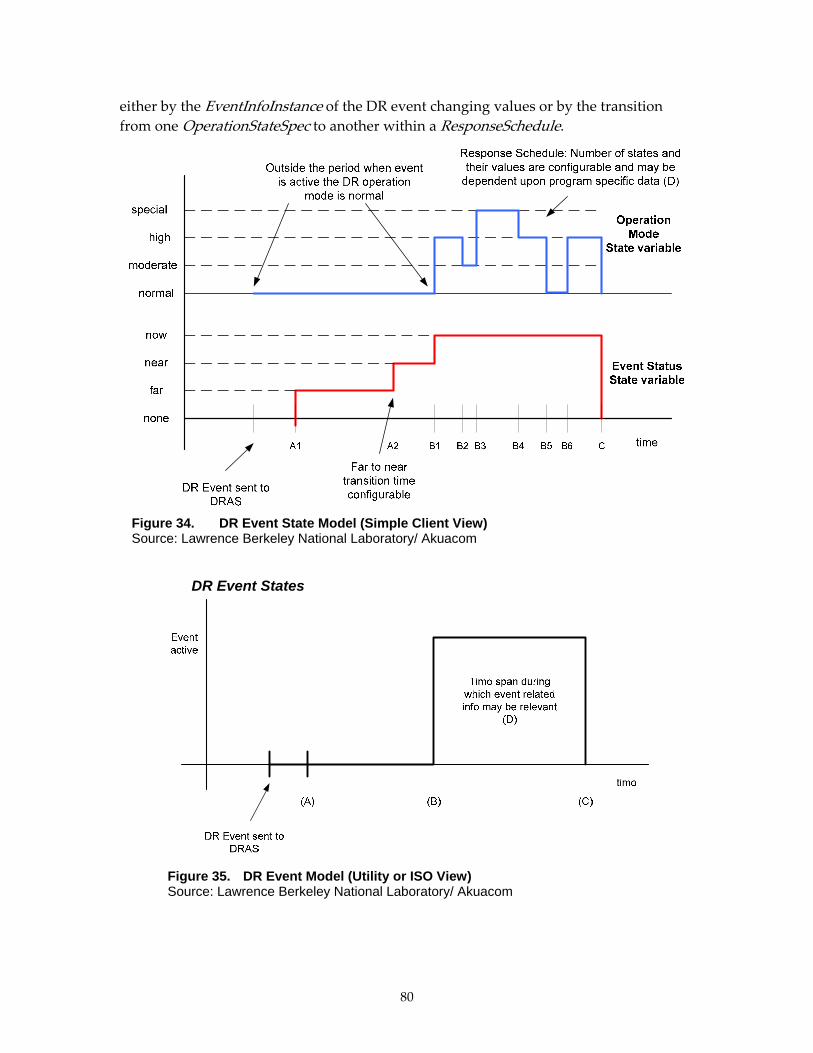
either by the EventInfoInstance of the DR event changing values or by the transition
from one OperationStateSpec to another within a ResponseSchedule.
Figure 34. DR Event State Model (Simple Client View) Source: Lawrence Berkeley National Laboratory/ Akuacom
DR Event States
Figure 35. DR Event Model (Utility or ISO View) Source: Lawrence Berkeley National Laboratory/ Akuacom
80

For reference purposes, the DR Event Model (Figure 16) is repeated here as Figure 35.
From the DRAS point of view a DRAS Client may be in one of the following modes of
operation:
opt‐in – DR events are handled and sent to the DRAS Client as they normally
would be.
opt‐out – The DRAS Client has opted out from receiving DR event information
and none will be sent when they are in this state.
Test – This is used for test purposes and is analogous to the DRAS Client being
off line. No DR events will be sent automatically from the DRAS, but a DRAS
installer may send test messages to the DRAS Client.
Note that the states listed above are all from the point of view of the DRAS and the
DRAS Client responds to the state the DRAS is in. It is the DRAS that changes its
behavior and where the logic resides in relation to the DRAS Client.
The DRAS is responsible for tracking the event states for each of the DRAS Clients in
order to send the DR event information to the DRAS Client at the appropriate time.
From the DRAS Client’s point of view there is a so‐called DR event state the DRAS
Clients are in which is represented by the EventState entity. Normally a DRAS Client’s
event state is “IDLE” meaning that there are currently no active or pending DR events.
This changes when the utility or ISO initiates a DR event in the DRAS. The DRAS tracks
the DR event state for each DRAS Client and can provide the current state information at
any time for that DRAS Client. It can be in different states, depending upon whether the
participant uses a Smart DRAS Client or a Simple DRAS Client.
Figure 36 is the state transition diagram for a general DR event. For a Smart DRAS Client
these are the only states that are relevant, but for a Simple DRAS Client there may be
sub states during the ACTIVE period which each represent the various level transitions
of the Operation Mode variable.
81

IDLE
PENDING
ACTIVE
DR Event Initiated by Utility/ISO AND current time = Event Issue Time
Current time = DR Event Start Time
DR Event End Time
Figure 36. Transition Diagram for a General DR Event Source: Lawrence Berkeley National Laboratory/ Akuacom
Figure 37 shows the example state transition diagram that corresponds to Figure 36.
Note that the large states correspond directly to Figure 36 and are the only states that
exist for a Smart DRAS Client, whereas the sub‐states within the ACTIVE state are
additional states that may exist for a Simple DRAS Client.
The notion of states are important because the transition times from one state to another
define the times when the EventState entity is sent from the DRAS to the DRAS Client in
PUSH mode. In PULL mode the DRAS Client polls the DRAS and it simply responds
with the appropriate EventState that corresponds to the time when the poll was made.
82

IDLESet Event Pending = noneSet Shed Mode = normal
ACTIVE
current time = DR Event End Time
PENDING
State A1Set Event Pending = far
State A2Set Event Pending = near
current time = A2
DR Event Initiated by Utility/ISO AND current time = Event Issue Time
Current time = DR Event Start Time
State B1Set Event Pending = now
Set Shed Mode = high
State B2Set Shed Mode = moderate
State B3Set Shed Mode = special
State B4Set Shed Mode = high
State B5Set Shed Mode = normal
State B6Set Shed Mode = high
current time = B2
current time = B3
current time = B4
current time = B5
current time = B6
Figure 37. DRAS Client DR Event State Simple DRAS Client State Transition Diagram Source: Lawrence Berkeley National Laboratory/ Akuacom
6.6. Demand Response Automated Bidding Models The DRAS may support automated bidding by participants into DR programs by
supporting the concept of a “standing bid” for that participant. A standing bid is a bid
that will be submitted by the DRAS for a participant if no other bid is submitted by the
participant. The ability to automatically submit standing bids increases the level of
participation in programs that require bidding. In some case the utility’s or ISO’s IT
infrastructure will already support the notion of standing bids and in those cases it is not
necessary for the DRAS to provide this functionality. In fact there may be scenarios
where there are programs that require bidding, but all the bidding is handled by a
different system than the DRAS, including the handling of standing bids. In this case,
from the DRAS point of view, the program will not require bidding and all the DR
events are simply issued by the utility or ISO as in the case of programs with no bidding.
The utility or ISO will simply handle all the bidding as they normally would and use the
DRAS to issue the DR events.
The remainder of this section assumes that the DRAS is handling the automated
submission of standing bids. From the participant’s point of view there is a so called bid
83

state that they are in (see Figure 37). Normally the state is “IDLE” meaning that there are
currently no outstanding requests for bids. This changes when the utility or ISO initiates
a DR event for a program that may require bidding. In this case the DRAS will issue a
request for bids by notifying the participant operators via email or some other means.
The DRAS then tracks the bid state for each participant and can provide the current state
information at any time for that participant. The state variables associated with each bid
request include:
Program – the program associated with requests for Bids.
Notify time – the time that participants are notified of the request for Bids.
Start time – the start time of the bidding
End time – the end time of the bidding
Bid info – this gives program and DR event related information related to
bidding.
The Bid entity is used by both the utility or ISO and the participants to represent bids as
described in Section 8.11. Bid state transition diagrams are shown in Figures 38 and 39.
There is a separate state diagram for each program and DR event that a participant may
submit bids for. The bidding sequences in Figure 38 are initiated by the utility or ISO
when they initiate a DR event for a program that requires bidding by the participant. In
some cases the bidding is open and closed according to some fixed schedule which is not
associated with a specific event. In this case the opening and closing of the entry of bids
is simply according to some schedule.
IDLE
BIDDING OPEN
AWAIT ACCEPTANCE
Bid request Initiated by Utility/ISO (DR Event initiated) AND current time = Notify Time
Current time = Bidding close time
Accept/Reject Notification ReceivedCancel Bids
Figure 38. State Transition Diagram for a Participant’s Bid State Source: Lawrence Berkeley National Laboratory/ Akuacom
84

Figure 39 shows the sequence diagram for the bidding process. Note the following:
Step 3 is optional and if it is not performed then the standing bid for the
participant is submitted.
Step 4a represents the submission of the bid to the utility or ISO after the bid is
submitted by the participant. If Step 3 is not performed by the participant then
this step is not performed. This step may happen immediately after Step 3 or at a
scheduled time (i.e. like Step 4b in Figure 38).
Step 4b is performed at a specifically scheduled time and represents the
submission of the standing bid if the participant does not manually submit a bid
as part of Step 3. Since this happens at a scheduled time, participants have time
to submit bids or change their standing bid.
Note that the DRAS should be configurable such that Step 4a is not performed
immediately after it is submitted by the participant, but rather at a scheduled time like
the standing bid is submitted.
Steps 2 and 6 are machine to human communications and can utilize either email
or some third‐party notification system.
Figure 39. Bidding Sequence Diagram Source: Lawrence Berkeley National Laboratory/ Akuacom
When the utility or ISO notifies the DRAS of all bid acceptances (step 5), the acceptances
come in the form of a list of UtilityDREvent entities that describe each of the DR events
85

86
that need to be issued to the participants whose bids were accepted. This allows for the
utility or ISO to customize a DR event for each participant that will reflect the bids that
they made. Note that it is a requirement that each of the UtilityDREvent entities that are
issued as part of the list of accepted participants have the SAME event identifier as the
original DR event that was issued and initiated the request for bids.
Upon receiving the list of UtilityDREvent that signify the participants whose bids were
accepted the DRAS will notify the participant operators (Step 6) and send the DR events
to the relevant DRAS Clients (Step 7).
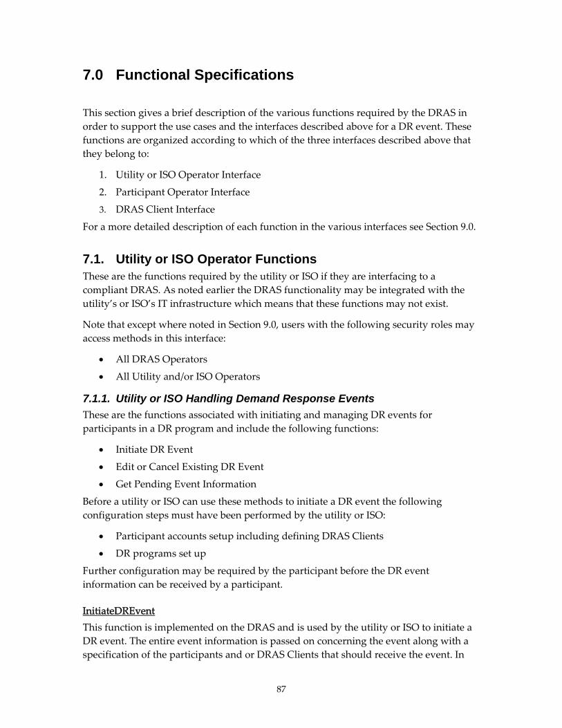
7.0 Functional Specifications
This section gives a brief description of the various functions required by the DRAS in
order to support the use cases and the interfaces described above for a DR event. These
functions are organized according to which of the three interfaces described above that
they belong to:
1. Utility or ISO Operator Interface
2. Participant Operator Interface
3. DRAS Client Interface
For a more detailed description of each function in the various interfaces see Section 9.0.
7.1. Utility or ISO Operator Functions These are the functions required by the utility or ISO if they are interfacing to a
compliant DRAS. As noted earlier the DRAS functionality may be integrated with the
utility’s or ISO’s IT infrastructure which means that these functions may not exist.
Note that except where noted in Section 9.0, users with the following security roles may
access methods in this interface:
All DRAS Operators
All Utility and/or ISO Operators
7.1.1. Utility or ISO Handling Demand Response Events
These are the functions associated with initiating and managing DR events for
participants in a DR program and include the following functions:
Initiate DR Event
Edit or Cancel Existing DR Event
Get Pending Event Information
Before a utility or ISO can use these methods to initiate a DR event the following
configuration steps must have been performed by the utility or ISO:
Participant accounts setup including defining DRAS Clients
DR programs set up
Further configuration may be required by the participant before the DR event
information can be received by a participant.
InitiateDREvent
This function is implemented on the DRAS and is used by the utility or ISO to initiate a
DR event. The entire event information is passed on concerning the event along with a
specification of the participants and or DRAS Clients that should receive the event. In
87

the case where bidding is required as part of the program then this method will initiate
the bidding process.
ModifyDREvent
This function is used to edit a previously issued DR event. It must reference the DR
event identifier that was assigned by the utility or ISO when the original event was
issued. The following types of modifications can be made to an already initiated DR
event:
Cancel a DR Event
Change the participant list
Modify DR Event parameters
AdjustDREventParticipants
This function will modify the list of participants that will receive an already existing DR
event. It is somewhat redundant with the functionality available with the more general
ModifyDREvent method, but is deemed to be done frequently enough to merit its own
method to make it easier.
GetDREventInformation
This function is used to get information related to currently pending or active DR events
within the DRAS.
SetEventConstraint
This method is used to set ProgramConstraint variables that are applied to a specific DR
event.
GetEventConstraint
This method is used to fetch the ProgramConstraint variables that are applied to a
specific DR event.
7.1.2. Utility or ISO Support for Automated Bidding
The following functions are used by the utility or ISO to manage the participant’s
bidding that is associated with a particular DR event. These functions include the
following:
Query the DRAS about existing bids
DRAS sends bids to the utility’s or ISO’s IT system
Close the bidding
Notify the DRAS of which bids were accepted or rejected
The bidding process proceeds as described in Section 6.6.
88

When participant bids are sent from the DRAS to the utility or ISO both a PUSH and
PULL model is supported by the DRAS. In the PUSH model the bid information is sent
by the DRAS to the utility or ISO by initiating the communications with the utility’s or
ISO’s IT system. It does this by invoking a function on the utility’s or ISO’s IT system.
In the PULL model the utility or ISO queries the DRAS for the bidding information by
invoking a function of the DRAS to retrieve the information.
GetCurrentBids (PULL MODEL)
This function allows the utility or ISO to request the current participant bids from the
DRAS. The utility or ISO can either request bids for a specific event or all the standing
bids for a specific program.
SetCurrentBids (PUSH MODEL)
This function is implemented on the utility’s or ISO’s IT system and allows the DRAS to
proactively send the participant’s bid information to the utility or ISO. It is beyond the
scope of this document as to how this method’s end point URL is specified and
configured or how the DRAS’ credentials for invoking this method are configured with
the DRAS.
CloseBidding
This function is used to explicitly close the bidding for a particular DR event. When
bidding is closed participants can no longer submit bids. When a DR event that requires
bidding is issued it has a time in which the bidding will close. This function can close
that bidding before that time.
SetBidStatus
This function is used to notify the DRAS of which previously submitted participant bids
have been rejected and accepted.
7.1.3. Utility or ISO Configure Demand Response Automation Server
These functions are used by the utility or ISO to configure the DRAS to support the DR
programs and specifically the delivery of DR events to the participants in the DR
program. The functions configure and edit the account and program information
associated with a DR program. The various data model entities associated with DR
programs from the utility’s and ISO’s point of view are described in Sections 6.4.1 and 0.
Depending upon the business process, the utility or ISO may also take responsibility for
performing the configuration of the data entities normally configured by the participant.
In that case the functions specified in Section 7.3 would also be performed by the utility
or ISO.
89

Manage Programs
The following functions are associated with managing DR programs within the DRAS.
From the point of view of the DRAS a DR program is represented by the UtilityProgram
entity and thus these functions represent the manipulation of that entity within the
DRAS.
CreateProgram
This function is used to create a new DR program.
ModifyProgram
This function is used to modify an existing program that was created with the
CreateProgram function.
DeleteProgram
This function is used to delete an existing program that was created with the
CreateProgram function.
GetPrograms
This function is used to get all the information related to programs including the
program constraints and event Info Types associated with the program.
AdjustProgramParticipants
This function is used to add or remove a participant from a program.
Manage Participant Accounts
The following functions are associated with managing participant accounts, and
specifically the management of those accounts as they relate to programs. Each
participant account is represented by a ParticipantAccount entity as described in
Sections 6.3.4 and 8.5. A ParticipantAccount object is associated with an UtilityProgram
object which allows the participant represented by that account to receive DR events
from the DRAS. In addition, a participant may have a set of ProgramConstraints that are
specific to how that participant operates within a specific program. Note that these are
different from the ProgramConstraints that were associated with the program as a
whole and are specific to the participant. This is described in more detail in Section 6.5.2.
CreateParticipantAccounts
This function is used to create one or more participant accounts.
ModifyParticipantAccounts
This function is used to modify existing participant accounts.
90

DeleteParticipantAccounts
This function is used to delete participant accounts that were created with the
CreateParticipantAccounts function.
GetParticipantAccounts
This function is used to fetch information related to participant accounts.
GetGroups
This function returns all the groups for all the participants.
7.1.4. Utility or ISO Monitoring of Demand Response Automation Server Related Activities
The DRAS logs various transaction and alarms as described in Section 6.3.2. The
functions described in this section provide a means to query those logs.
GetDRASClientCommsStatus
This function is for retrieving a DRAS Client’s current communication state.
GetDRASTransactions
This function is used to retrieve any of the transaction logs associated with the DRAS.
GetDRASClientAlarms
This function is used to retrieve DRAS Client Alarms that have been logged within the
DRAS.
GetParticipantFeedback
This function is used to fetch a list of Feedback objects based upon a set of search
criteria.
7.2. Demand Response Automation Server Client Functions This section is a functional description of the methods required for the DRAS and DRAS
Client to exchange information concerning DR events. As described above there is both
a PUSH and a PULL model of interaction between the DRAS and the DRAS Client. In
both cases an EventState entity is passed from the DRAS to the DRAS Client and a
Confirmation message is sent from the DRAS Client to the DRAS to acknowledge receipt
of the message. Section 8.12 gives a detailed description of the EventState and
EventStateConfirmation entities.
This section only specifies the functional requirements of the methods that are to be
implemented on the DRAS and the DRAS Client. Unlike other functions described in
this section that are intended to be implemented using SOAP, there are in fact a number
of different ways in which the functions in this section can be implemented such as
91

BACnet Web services and simple REST (Representational State Transfer). See Section 9.3
for a more detailed description of the actual methods that are used.
Send DR Event Information (PUSH) to DRAS Client
This function is implemented on the DRAS Client. An EventState entity is sent by the
DRAS to a DRAS Client whenever the participant’s DR event state changes or when the
DR event information has been changed by the utility or ISO. This includes canceling the
DR event. When the DRAS Client receives the EventState entity it must send the DRAS
an EventStateConfirmation entity as described in Section 6.5.3. Sending the confirmation
message includes the DRAS Client invoking the method on the DRAS that is used for
sending confirmation messages as described in Section 6.5.3. See Section 8.12 for a
description of the EventState object.
Get DR Event Information (PULL for DRAS Client)
This function is used in the PULL model of interaction between the DRAS and DRAS
Client to fetch information concerning any pending DR events. It logically operates the
same as its PUSH cousin and allows the exchange of the same information. When the
DRAS Client receives the EventState entity it must send the DRAS an
EventStateConfirmation entity as described in Section 8.12. As part of the security policy
the DRAS must ensure that the security credentials that were used by the DRAS Client
to invoke this function match the various parameters passed into this function.
Parameters
Participant ID
Program ID
DRAS Client ID (for example, username and password)
Return Values
An EventState object as described in Section 8.12.
Authorized Users
All DRAS Operators
DRAS Client associated with the Participant ID
Send Event State Confirmation to DRAS
This function is implemented on the DRAS and is used by the DRAS Client to send
confirmation that it has received a specific instance of an EventState object. If this
function is not invoked by the DRAS Client within the time out period after the DRAS
sends an EventState object the DRAS must assume that the EventState object was not
received properly by the DRAS Client. As part of the security policy the DRAS must
ensure that the security credentials that were used by the DRAS Client to invoke this
function match the various parameters associated with the EventStateConfirmation
object.
92

Note that the EventStateConfirmation object also contains a flag which specifies whether
the DRAS Client is opting in or out of the DR event. An EventStateConfirmation object
can therefore be used to initiate the opt‐out state at the DRAS Client and to notify the
DRAS of this state. Since the opt‐out state can be set within the DRAS Client at any time,
the EventStateConfirmation object can be sent at any time using a previously confirmed
EventState.
Parameters
EventStateConfirmation object as described in Section 8.12.
Return Values
SUCCESS or FAILURE
Authorized Users
All DRAS Operators
DRAS Client associated with the EventState Confirmation object.
7.3. Participant Operator Functions The functions described in this section are part of the participant operator interface. In
general users with the following security roles may access the functions within this
interface:
All DRAS Operators
All Utility or ISO Operators
All Participant Managers
For security reasons if the role of the user accessing this method is a participant manager
then the user name or password of the participant manager must match the user name
or password on the participant accounts that are associated with the return values.
Also a few of the functions described in this section may be accessed by user with the
DRAS Client installer security role.
7.3.1. Opting Out of Demand Response Events
An opt‐out state is a set of conditions for which the participant will not be participating
in DR events. An opt‐out state is represented by the OptOutState entity as described in
Section 8.6, opt‐out states can be based upon specific DR events, programs, or DRAS
Clients. In addition there can be a schedule associated with an opt‐out state. There may
be multiple opt‐out states associated with a participant and the DRAS must check each
of the configured opt‐out states to determine if a participant will receive a DR event. It is
implementation specific for the DRAS to define what happens if an opt‐out schedule
starts or ends in the middle of a DR event period.
93

The functions in this section are for managing opt‐out states for participants. Participant
managers can only manage opt‐out states for accounts that are associated with their
ParticipantAccount.
The functions described in this section may also be used by the automation system in the
facility in the use case where the opt‐out state of the facility is set at the automation
system and not through some specific user interface on the DRAS. Note that the opt‐out
state of a facility can also be set through the DRAS Client interaction by using the
EventStateConfirmation which contains a flag that specifies whether the DRAS Client is
opting out of a DR event.
CreateOptOutState
This function is used to create an opt‐out state for a participant.
DeleteOptOutState
This function is used to delete a previously created opt‐out state for a participant.
GetOptOutState
This function is used to fetch opt‐out states for a participant.
7.3.2. Submitting Feedback (Facility Status) to Demand Response Automation Server
These functions are used by the participant to provide feedback concerning the status of
the facility. The manner in which the feedback is provided might include a number of
different actors including both human and machine which may include the DRAS
Client.
SetDREventFeedback
This function is used to send information to the DRAS concerning the state of the facility
and how the participant or DRAS Client reacted to the DR event being issued. Note that
in general feedback may be sent at any time and may or may not be associated with a
specific DR event.
GetDREventFeedback
This function is used to fetch a list of feedback objects that were created with the
SetDREventFeedback function.
7.3.3. Automated Bidding
The functions described in this section are used by the participants to manage their bids
that are associated with those DR events that require bidding. Bids are represented by
the Bid entity. The bidding process is described in Section 6.6.
SubmitStandingBid
94

This function is used to set a participant’s standing bid for a program.
GetStandingBid
This function is used to fetch a participant’s standing bid for a program.
DeleteStandingBid
This function is used to delete a participant’s standing bid for a program.
SubmitBid
This function is used to set a participant’s real‐time bid for a program.
GetBid
This function is used to fetch a participant’s real‐time bid for a program.
7.3.4. Configuration of Participant Related Information in Demand Response Automation Server
These functions are used by the participants to configure the DRAS for the reception of
DR events that are associated with a specific program. The following entities are
managed by the participant and are involved in how they operate and receive DR
events:
ParticipantAccount
DRASClient
ResponseSchedule
ProgramConstraints
Note that it is not a requirement that the utility or ISO allow access by any participant to
the configuration functions detailed in this section. In that case all configuration
functions would be performed by a utility or DRAS operator.
Manage Participant Accounts
The participant accounts are created by the DRAS or the utility or ISO operators. It is not
required that the DRAS allow access to ParticipantAccount information by the
participant. The DRAS may be configured to operate in a number of different ways:
Participant has no access to ParticipantAccount information and the utility or
ISO is responsible for all configuration of this information as described above.
Participant may view, but can not modify any of the fields in the
ParticipantAccount entity.
Participant can both view and modify the information in the ParticipantAccount
entity.
95

It is beyond the scope of this document to specify how the DRAS is configured to
operate in one of the modes described above, but it is the assumption of this section that
it is configured to operate in mode 2 or 3 as described above.
GetParticipantAccounts
This function is used to get the participant’s account information (ParticipantAccount).
ModifyParticipantAccount
This function is used to modify existing participant accounts. While certain fields of the
ParticipantAccount may be viewed by a participant manager, they may not be modified.
These fields include the following:
Participant uid
Participant name
User name
Program names
Managing DRAS Clients
Each participant may have multiple DRAS Clients associated with their account. These
functions are used to manage the DRAS Clients.
CreateDRASClient
This function is used to create a DRAS Client. Note that program constraints and
response schedules may be created through a separate set of functions and need not be
created using this function.
ModifyDRASClient
This function is used to modify an existing DRAS Client.
DeleteDRASClient
This function is used to delete an existing DRAS Client.
GetDRASClientInfo
This function is used to fetch DRAS Client information associated with participant.
Managing Program Constraints
These functions are used to manage program constraints. A participant’s program
constraints are always associated with a particular program and in addition they are also
associated with either the participant account as a whole or a specific DRAS Client.
Therefore these functions are used to manage both the program constraints that are for a
participant as a whole as well as the constraints that are associated with a specific DRAS
Client.
96

GetParticipantProgramConstraints
This function is used to fetch the ProgramConstraints object associated with the
participant as a whole.
SetParticipantProgramConstraints
This function is used to assign the ProgramConstraints object associated with the
participant as a whole.
DeleteParticipantProgramConstraints
This function is used to delete the ProgramConstraints object associated with the
participant as a whole.
GetDRASClientProgramConstraints
This function is used to fetch the ProgramConstraints object associated with a specific
DRAS Client.
SetDRASClientProgramConstraints
This function is used to assign the ProgramConstraint object associated with a specific
DRAS Client.
DeleteDRASClientProgramConstraints
This function is used to delete the ProgramConstraint object associated with a specific
DRAS Client.
Managing Simple DRAS Client Response Schedules
As described in Section 0, response schedules are primarily intended for Simple DRAS
Clients and are used to specify how to translate the EventInfo information associated
with a DR event into the simpler Operation Mode variable transitions during the
ACTIVE period of the DR event. The ResponseSchedule entity is used to define these
translation rules and is associated with specific programs and DRAS Clients.
In order to create a ResponseSchedule for a DRAS Client the following information is
required from the DRAS and may be used by a participant UI to create a
ResponseSchedule:
List of all EventInfoTypes that may be associated with the program in question.
A consolidated set of ProgramConstraints that apply to a particular DRAS Client.
If there is an explicit set of program constraints defined for a DRAS Client then
those are used, else if there are program constraints defined for the participant as
a whole then those are used, else the program constraints that are defined for the
program as a whole is used.
97

Because of the way that program constraints are defined it is always possible to derive a
set of ProgramConstraints that will be applied to a particular DRAS Client for a specific
program.
With this information it should be possible to build a tool or editor that can be used to
create response schedules.
The functions described in this section are used to manage the response schedules.
GetProgramInformation
This function is used to retrieve the information necessary to help an operator edit and
specify a response schedule and its operating states.
CreateResponseSchedule
This function is used to create a ResponseSchedule for a specific DRAS Client and
program.
DeleteResponseSchedule
This function is used to delete a ResponseSchedule for a specific DRAS Client and
program.
GetResponseSchedule
This function is used to fetch a ResponseSchedule for a specific DRAS Client and
program.
7.3.5. Monitoring of Demand Response Automation Server Related Activities
The DRAS logs various transaction and alarms as described in Section 6.3.2. The
functions described in this section provide a means to query those logs.
GetDRASClientCommsStatus
This function is for retrieving a DRAS Client’s current communication state.
GetDRASTransactions
This function is used to retrieve any of the transaction logs associated with the DRAS.
GetDRASClientAlarms
This function is used to retrieve DRAS Client Alarms that have been logged within the
DRAS.
98

99
7.3.6. Installation and Testing of Demand Response Automation Server Clients
These functions are used to test the communications between a DRAS Client and the
DRAS. It does this by allowing the DRAS Client to be put into test mode. When a DRAS
Client is in the test mode of operation then it is considered to be off line by the DRAS
and does not receive normal EventState messages when DR events occur. If the DRAS
Client is a Simple DRAS Client then these functions can be used to manually set the
Operation Mode values of the DRAS Client. In the case of a Smart DRAS Client it can be
used to test the reception of EventState messages.
SetTestMode
This function puts a DRAS Client into or out of test mode. If a DRAS Client is in test
mode then it is essentially off line and will not receive any automated DR signals from
the DRAS.
SetTestModeState
This function sends a test message to a DRAS Client and if it is a Simple DRAS Client
then it can be used to set the operation mode and event state values. The DRAS Client
must be in test mode for this method to work.
GetTestModeState
This function is used to get the current operation state of the DRAS Client if it is in test
mode.

100

8.0 Detailed Data Models and Schemas
The detailed schemas described in this section are all specified and documented using
XML Schema Definition (XSD). All the documentation for the schemas is embedded in
their respective XSD schema files. What is displayed in this section is simply a human
readable form of that documentation that was extracted from the XSD file using a
particular tool. If so desired the reader may take the machine readable source XSD file
and browse it with a tool of their choosing.
The recent XSD versions are available on the LBNL Website– http://openadr.lbl.gov/src/.
For example, http://openadr.lbl.gov/src/EventState.xsdrefers to the EventState.xsd
source file.
8.1. UtilityProgram See UtilityProgram.xsd
8.2. UtilityDREvent See UtilityDREvent.xsd
8.3. ResponseSchedule See ResponseSchedule.xsd
8.4. ProgramConstraint See ProgramConstraint.xsd
8.5. ParticipantAccount See ParticipantAccount.xsd
8.6. OptOutState See OptOutState.xsd
8.7. Logs See Logs.xsd
8.8. Feedback See FeedBack.xsd
101

8.9. EventInfo See EventInfo.xsd
8.10. DRASClient See DRASClient.xsd
8.11. Bid See Bid.xsd
8.12. EventState See EventState.xsd
102

9.0 Detailed Application Programming Interface Specifications
The detailed Application Programming Interfaces (APIs) described in this section are for
the most part specified using a Web Service Description Language (WSDL), which is the
standard method for specifying a SOAP Web service interface. All the documentation
for the methods and their parameters specified in the APIs are embedded in their
respective WSDL files. What is displayed in this section is simply a human readable
form of that documentation that was extracted from the WSDL file using a particular
tool. If so desired the reader may take the source WSDL file and browse it with a tool of
their choosing.
Recent API versions are posted on the LBNL Website (http://openadr.lbl.gov/src/) and
include Bacnet DRAS Definition and DRAS Instance XML files For example;
http://openadr.lbl.gov/src/bacnet.wsdl refers to the bacnet.wsdl source file.
9.1. Utility Program Operator APIs This section details the methods in the API that are provided for the utility program
operator methods as described in this section. There is a one to one correspondence
between the functions described in that section and the method documentation
presented here.
See UtilityOperator.wsdl
See UtilityInterface.wsdl
9.2. Participant Operator APIs See ParticipantOperator.wsdl
9.3. DRAS Client APIs This section details the methods of the API that are used for the communications
between the DRAS and a DRAS Client. As previously discussed, the DRAS Client API is
responsible for communicating DR EventState information to the DRAS Client in the
participant’s facility whether it is an end user or an aggregator. This API also includes
the EventStateConfirmation message that is also sent from the DRAS Client to the DRAS
upon receipt of the EventState information. See Sections 6.5.3 and 7.2 for a more detailed
description of this interaction.
Many potential DRAS Clients are limited in capabilities and not sophisticated enough to
support a SOAP interface. Therefore there are three distinct types of interfaces described
here–one using a simple REST type of Web service interface, a simple SOAP type of
Web service, and one using a more sophisticated SOAP interface that utilizes a BACnet
Web Services (BWS) interface.
103

The DRAS must support the BACnet simple SOAP Web service interface and may
support the simple REST Web service interface and may support the BACnet SOAP Web
service interface. Table 4 below indicates (with ‘X”) the required and optional services to
be supported by this OpenADR specification and their supporting communication
models.
Table 4 Required Services and Supported Communication Models
DRAS Client API Required PUSH PULL
Simple REST Services X
Simple SOAP Services X X X
BACnet SOAP Service (CSML) X X
CSML = Control Systems Modeling Language Source: Lawrence Berkeley National Laboratory/ Akuacom
9.3.1. Use of Simple REST Services to Exchange DR EventState Information
It is recommended that DRAS Clients use a SOAP interface to the DRAS, but for DRAS
Clients with limited communications capabilities that do not support a full SOAP
protocol stack, the simple REST interface presented in this section is a means to interface
to the DRAS and exchange DR event information. The REST interface must support all
the requirements of the DRAS Security Policy as described in Section 10.
The REST interface does not support the PUSH model of interaction with the DRAS. A
DRAS Client interacting with the DRAS uses Hyper Transfer Text Protocol (HTTP) Get
to fetch EventState entities from the DRAS and subsequently uses HTTP Post to send the
EventStateConfirmation messages back to the DRAS. This is depicted in the sequence
diagram in Figure 40.
Figure 40. REST DRAS Client PULL Interaction Sequence Diagram Source: Lawrence Berkeley National Laboratory/ Akuacom
104

When the HTTP GET is invoked the DRAS returns an EventState entity. The EventState
When the HTTP POST is invoked to send the confirmation message an
tity is
Note that the path names used to access these services are implementation specific and
9.3.2. Use of Simple SOAP Services to Exchange DR EventState
capabilities to support a full SOAP protocol stack, the simple
The DRAS and supporting DRAS Client should exchange EventState information using
s
Using PULL architecture, the DRAS Client uses simple SOAP service to fetch the
ses simple SOAP service to
mple
nce diagram Figure 41, in the PUSH mode of interaction the
e
d
pt
entity is documented in Section 8.12.
EventStateConfirmation entity is posted. The EventStateConfirmation en
documented in Section 8.12.
not covered in this document.
Information
For DRAS Clients with
SOAP interface presented in this section is a means to interface to the DRAS and
exchange DR event information. The simple SOAP interface must support all the
requirements of the DRAS Security Policy as described in Section 10.
two different modes of interaction–PUSH and PULL–as described earlier in “Section
6.5.3.1, Modes of Interaction (PUSH versus PULL).” The following message exchange
must be supported by simple SOAP services:
entire XML message of DR EventState information.
Alternatively, using PUSH architecture, the DRAS u
send the entire XML message of DR EventState information to DRAS Client.
The DRAS Client at the facility parses the values of EventState information.
For both PUSH and PULL architecture, the DRAS Client at the facility
acknowledges with EventStateConfirmation message to DRAS using si
SOAP service.
As shown in the seque
EventState information is “pushed” from the DRAS to the DRAS Client using simpl
SOAP service. This means, the communication of the EventState information is initiate
by the DRAS. In terms of Web services this means that that DRAS Client is the Web
server and the DRAS is the Web client. The DRAS Client must acknowledge the recei
of message using EventStateConfirmation message.
105

Figure 41. Simple SOAP PUSH Model Sequence Diagram Source: Lawrence Berkeley National Laboratory/ Akuacom
As shown in the sequence diagram Figure 42, in the PULL mode of interaction the
EventState information is “pulled” from the DRAS by the DRAS Client using simple
SOAP service. This means, the communication of the EventState information is initiated
by the DRAS Client. In other words the DRAS Client polls the DRAS for the EventState
information. In terms of Web services this means that the DRAS is the Web server and
the DRAS Client is the Web client. The client must acknowledge the receipt of message
using EventStateConfirmation message.
Figure 42. Simple SOAP PULL Model Sequence Diagram Source: Lawrence Berkeley National Laboratory/ Akuacom
Simple SOAP Web Services API
This simple SOAP services API and the minimum methods that must be supported are
as described in Section 9.3.1 that are similar for simple REST services. The EventState
entity is documented in Section 8.12 and the EventStateConfirmation entity is
documented in Section 8.12.
106

9.3.3. Use of BACnet Web Services to Exchange DR EventState Information
For those requiring interoperability with BACnet, this OpenADR specification may
optionally use the BACnet Web Services (BWS) specification (ANSI/ASHRAE
Addendum C to Standard 135‐2004) to communicate with BACnet‐based systems.
The generic BWS data model allows interoperability with DRAS‐issued DR event
information and to schedule response strategies using Smart and Simple DRAS clients.
The DRAS‐BACnet Server and supporting DRAS Client should exchange EventState
information using two different modes of interaction–PUSH and PULL–as described
earlier in “Section 6.5.3.1, Modes of Interaction (PUSH versus PULL).”
To enable interoperability between the DRAS and BACnet‐based controls implementing
BWS, the following message exchanges must be supported:
Using PULL architecture, the Client uses BWS’ simple getValue service to read
the entire XML message of DR EventState information as String value from the
DRAS‐BACnet Server.
Alternatively, using PUSH architecture, the DRAS‐BACnet Server uses BWS’
simple setValue service to send the entire XML message of DR event state
information as String value to the DRAS Client.
The DRAS Client at the facility parses the String value of EventState information.
For both PUSH and PULL architecture, the DRAS Client at the facility
acknowledges with the String value of EventStateConfirmation information to
the DRAS‐BACnet Server using BWS’ simple setValue service.
As shown in the sequence diagram Figure 43, in the PUSH mode of interaction the
EventState information is “pushed” from the DRAS‐BACnet Server to the DRAS Client
to a pre‐defined node path of a tree using setValue service. This means, the
communication of the EventState information is initiated by the DRAS‐BACnet Server.
In terms of Web services this means that that DRAS Client is the Web server and the
DRAS‐BACnet Server is the Web client. The root of the tree is “DRAS” and the event
state is written to node “DRAS/EventState.” For real‐time pricing this node is
“DRAS/RTP.” The DRAS Client must acknowledge the receipt of message using
EventStateConfirmation message to the same node within specified timeout period
using setValue service.
107

Figure 43. BWS PUSH Model Sequence Diagram Source: Lawrence Berkeley National Laboratory/ Akuacom
As shown in the sequence diagram Figure 44, in the PULL mode of interaction the
EventState information is “pulled” from the DRAS‐BACnet Server by the DRAS Client
from a pre‐defined node path of a tree using getValue service. This means, the
communication of the EventState information is initiated by the DRAS Client. In other
words the DRAS Client polls the DRAS‐BACnet Server for the EventState information.
In terms of Web services this means that the DRAS‐BACnet Server is the Web server and
the DRAS Client is the Web client. The root of the tree is “DRAS” and the event state is
read from node “DRAS/EventState.” For real‐time pricing this node is “DRAS/RTP.” The
client must acknowledge the receipt of message to the same node using setValue service.
Figure 44. BWS PULL Model Sequence Diagram Source: Lawrence Berkeley National Laboratory/ Akuacom
108

Services Supported by DRAS-BACnet Server
While BWS has many services that support various aspects of control systems
specifications, most of them are not relevant to the DRAS‐BACnet server and getValue
and setValue services are being used. The other two services getDefaultLocale and
getSupportedLocals are required as per BWS specifications and must also be supported
by the DRAS to exchange DR event data with the DRAS‐BACnet server. These services
are described in brief below. Refer BACnet Web Services (BWS) specification
(ANSI/ASHRAE Addendum C to Standard 135‐2004) for further details such as
structure and procedures.
getValue Service
This BWS service is used to retrieve a single value for a single attribute of a single node.
This service always returns its results as a single string.
This service can be used to retrieve primitive attributes, such as Value, and array
attributes, such as PossibleValues. The format of this string result is dictated by the
attributeʹs datatype and the service options.
If this service is used for an array attribute, then the array elements shall be
concatenated into a single semicolon delimited string that can be easily split at the client
since the element strings are not allowed to contain semicolon characters. If the client
would rather retrieve an array of individual strings, it can use the getArray or
getArrayRange service instead.
A typical programming language signature for this service is:
CString getValue(CString options, CString path)
setValue Service
This BWS service is used to set a new value for a single attribute of a single node. The
format of the new value is dictated by the attributeʹs datatype and the service options.
This service always returns its results as a single string.
If the service option ʺreadbackʺ is true, then, after setting the value, this service shall
read the value back and the result shall be as if the client had called getValue using the
same path and service options. This allows the client to see the effects of any value
modification by the server as well as check for errors.
Only the Value attribute is writable.
This service is required to be provided if the setValues service is provided.
A typical programming language signature for this service is:
CString setValue(CString options, CString path, CString Value)
getDefaultLocale Service
109

This BWS required service retrieves the locale that the server has configured for its
default locale. The empty string (ʺʺ) shall be returned if there is no default locale, in
which case the canonical form shall be used for all values.
A typical programming language signature for this service is:
CString getDefaultLocale (CString options)
getSupportedLocals Service
This BWS required service can be used to retrieve the list of locales supported by the
server. If the server does not support multiple locales, then this service shall return only
the default locale. If the server does not support localization, and only uses the canonical
form, then an array with no entries shall be returned unless the noEmptyArrays service
option is true, in which case the result array shall contain a single entry for the
WS_ERR_EMPTY_ARRAY error condition.
A typical programming language signature for this service is:
CString[] getSupportedLocales (CString options)
EventState Schemas Used for the BACnet Interface
The DRAS‐BACnet server EventState schema information is represented using Control
System Modeling Language (CSML), which is both a data definition and data instance
language. While the CSML file with DRAS information and data structure is machine
and human readable and has an XML schema for validating the CSML file; however, the
CSML in itself is a schema for control systems data model. The definition file defines the
simple data structure of EventState schema and an instance file has instances of these
data structures. Together these files represent implementation of devices, objects, and
properties within a given device or collection of devices1.
XML schema is adequate for defining the structure of the CSML file, but is not rich
enough to capture all the information that is needed to fully define a BACnet control
systemʹs data structure, presentation, and semantics. These definition and instance
CSML files reference the schema defined in the supported BWS XSD file. An example of
CSML implementation and supporting XSD are detailed below:
See DR‐034E‐22w2 Example DRAS Definition.xml
See DR‐034F‐22w2 Example DRAS Instance.xml
1 http://xml.coverpages.org/facilitiesXML.html#csml
110

BACnet Web Services API
This section details the BWS services in the API that should be provided for the BACnet
methods. This API includes all BACnet services and the minimum methods that must be
supported are described in Section 9.4.2.
See bacnet.wsdl.
111

112

10.0 Security Policy This section outlines the security policy of the communications with the DRAS and
identifies the minimum security elements and interfaces that are required by this
OpenADR specification.
10.1. Scope
In general there are many modes of attacks upon any sort of IT infrastructure ranging
from intruders gaining physical access to the servers to remotely accessing the servers
through open communication channels. This OpenADR specification only covers the
communication protocols used to interact with the DRAS and the DRAS Clients. It is
therefore only intended to cover modes of attack that would be perpetrated by using one
of the communications channels that are used to implement the interface to the DRAS as
described in the analysis section of Appendix C. Any other certainly necessary security
measures (firewalls, intrusion detection, etc.) are not covered.
The DRAS has three distinct Web service interfaces, named after their principal users,
who are subject to this security policy:
1. Utility and ISO Operator Interface
2. Participant Operator Interface
3. DRAS Client Interface
The DRAS Client has one Web service interface (DRAS Interface) that is addressed by
the DRAS.
As described above, both the DRAS and the DRAS Clients can act as a server or a client
in a client/server relation.
10.2. Access Control and Security Roles
There are a number of types of users that require access to the DRAS. Each user may
have different requirements on the type of functions they can perform and data they
may access. To support limiting the access of the DRAS users based on their
requirements, the DRAS must support the security roles outlined in Section 6.3.1.
These security roles are designed to limit access to the various methods in each of the
Web service interfaces. Table 5 describes how each of the security roles is limited within
each of the Interfaces.
113

Table 5 Security Roles of Interfaces
Utility Interface
Participant Interface DRAS Client Interface
DRAS Interface on DRAS Client
DRAS n/a* n/a* n/a* Full Access DRAS Operator Full access Full access Full access none Participant Operator
none Access to all methods, but limited scope in what can be done, viewed, etc. with each method.
none none
Utility Program Operator
Full access Full access none none
DRAS Client none None Full access n/a* DRAS Client Installer
none Limited to a limited number of methods used for testing.
none none
*n/a–not applicable Source: Lawrence Berkeley National Laboratory/ Akuacom
For many of the functions described in this document the DRAS must limit the
invocation of the data and methods that are accessible based upon the credentials of the
user who is accessing the function. For example if a user with the participant operator
role accesses the GetParticipantAccount function it must only have access to those
ParticipantAccount entities that match the credentials of the user accessing the function.
The various access restrictions based upon the security roles is documented with each
function described above.
Additionally, for time‐critical services, the DRAS can establish a connection to the DRAS
Clientʹs DRAS interface for performing a PUSH transaction.
All public communication interfaces are subject to the following requirements
[RFC4949]:
Confidentiality: The content of communication and the identity of users must be
protected from third parties
Integrity: Communication must be protected from manipulation
Authentication: Communication is only allowed between authenticated and
known partners
Non‐repudiation: Transactions and message delivery can not be denied neither
by the origin nor the recipient.
These requirements can be addressed via one of the following methods:
DRAS Sec Method A: Secure tunnel with server‐side certificates in conjunction
with username or password client authentication
DRAS Sec Method B: Secure tunnel with server‐side and client side certificates
DRAS Sec Method C: Web Services Security (reserved for future use, not
described in this version)
114

Additionally, authenticated clients have individual visibility of the respective serverʹs
data and services. This access control is specifically addressed in the detailed
documentation for each method in the DRAS API. For each method the following is
specified:
The security role is allowed access to the method.
For particular security roles the type of information is allowed to be returned for
each method. For example, a user with the participant manager role can only
access information that is related to the participant account that they are
associated with.
Security Management like key and certificate distribution, firmware updates, key
revocation, etc. is implementation dependent and thus not in the scope of this document.
The Secure Tunnel, Transport Layer Security Protocol (TLS), Version 1.0 (or newer) with
Rivest, Shamir & Adleman PK cryptography (RSA) extension has been chosen.
Certificate revocation lists must be used. Each transaction is a separate TLS Sessions that
is terminated after the response. The following cipher suite choice reflects the most
interoperable selection of state‐of‐the‐art TLS APIs at creation of the OpenADR
specification and shall be considered as a minimum level and must‐have for the DRAS.
The additional support for stronger ciphers is explicitly encouraged, as long as they are
part of the official TLS specification as published by the Internet Engineering Task Force (IETF):
Key exchange: RSA1024
Data Encryption: 3DES (Data Encryption Standard), AES128 (Advanced
Encryption Standard)
Message Integrity Code (MIC): Secure Hash Algorithm (SHA1) – MIC: SHA1
Message Authentication Code (MAC): Hashed MAC (HMAC) – MAC ‐ HMAC‐
SHA1
The stable state of the system is that all API interfaces satisfy the above requirements up
to a certain extent that corresponds to the particular threat level and system value.
Reaching this state depends on the particular implementation. If the security of one
interface depends on the security of another interface (e.g. a cryptographic key for
interface A derived from a password that is received by a human user via interface B
and entered via interface C), it must be shown that the entire information chain satisfies
the overall security requirements. Key distribution and management is therefore
considered implementation dependent.
An implementation chooses the security measures for the non‐API interfaces according
to the usage scenario, threat levels, protected values, etc. The minimum level, given in
this document, might (Client A) or might not (Client B and C) be right for a particular
implementation as examples shown in Figure 45. Higher security measures can easily be
integrated into the DRAS if necessary (Client C) as long as they are based on open
115

standards. Communication partners with lower security levels (Client B) have to use a
security proxy.
ClientA ClientB
Proxy
ClientC
DRAS
Figure 45. DRAS Communication Partners with Different Security Levels Source: Lawrence Berkeley National Laboratory/ Akuacom
The choice of security technologies like ciphers shall be limited to those that are open
with freely available standards.
116

11.0 Future Developments This document represents a multi‐year and multi‐institutional effort to define how the
DR signaling between utilities or ISOs and commercial and industrial facilities is
performed to automate the process of issuing and responding to DR events and dynamic
prices. Many aspects of the data models described in this document are already
demonstrated and are in use in a variety of DR programs. The next steps in developing
the OpenADR specification will include the following objectives:
Expand OpenADR to additional DR programs and dynamic tariffs to gain more
experience with new use cases.
Engage a larger audience of stakeholders and industry experts to further develop
the OpenADR specification.
Continue collaboration with formal industry standards development
organizations.
Objectives 2 and 3 are being satisfied by creating OpenADR groups within both the
Utility Communications Architecture (UCA) International Users Group1 and
Organization for the Advancement of Structured Information Standards (OASIS)2. Both
these groups are highly respected with strong ties to formal standards groups like
International Electrotechnical Commission (IEC)3. Future development of the OpenADR
specification will take place within UCA and OASIS with the objective of moving
OpenADR to a formal standards organization such as IEC. There will be a high degree
of cooperation between UCA and OASIS and with each playing a complementary role in
the further development of the OpenADR specification.
The official public review period was between May and July 2008, with comments
accepted until November 2008. A significant number of comments were submitted by a
variety of stakeholders. While many of the comments were addressed in this version,
some will be addressed in future revisions within the UCA or OASIS. A detailed
compilation of all the comments received can be found at http://openadr.lbl.gov/. The
following is a general characterization of the type of issues that will be addressed in
future OpenADR specification development:
Feedback from Facilities to Utility or ISO: While the current version of the
document has interfaces for providing feedback information from the facility to
the utility or ISO, further analysis is required for more detailed specification(s) to
address specific types of feedback such as control strategy or electricity load
information.
Security of Communications Channel: While a comprehensive security analysis
is provided in this document, there are a number of issues such as scalability,
1 UCA International Users Group: http://www.ucaiug.org/ 2 OASIS: http://www.oasis‐open.org/ 3 IEC: http://www.iec.ch/
117

118
interoperability, and credential management that could benefit from further
analysis. In addition, it may be beneficial to harmonize the security policies with
entities within OASIS and UCA.
Network Scalability: Further detailed analysis for very high volume message
traffic.
Readability: Evaluate the need to categorize key elements of the specification.
The current specification contains interfaces for the utility or ISO and
participants. It may be beneficial to modify and separate the specification into
more than one document, with the initial focus on the utility or ISO to participant
communications.
Expansion of Client Interfaces: Support additional DRAS Client interfaces such
as Object Linking and Embedding (OLE) for Process Control (OPC) Unified
Architecture (OPC‐UA).
Harmonization: Evaluate OpenADR harmonization with other industry efforts
that are standardizing models for common data entities such as dynamic pricing.
Ancillary Services: Explore the use of OpenADR in other markets such as
wholesale and ancillary services.
Implementation Guidelines: Develop OpenADR implementation and compliance
guidelines to foster interoperability.
Benefits to California
OpenADR will provide benefits to California by both increasing the number of facilities
that participate in demand response, and reducing the cost to conduct frequent and
persistent participation in demand response. Furthermore, OpenADR will improve the
feasibility of achieving the stateʹs policy goals of moving toward dynamic pricing, such
as critical peak or real time pricing, for all customers. Increasing participation in
demand response reduces the need for new electric supply, reduces the need for new
transmission and distribution systems, and helps reduce overall electricity prices.

12.0 Definitions, Acronyms and Abbreviations For the purposes of this report, the following terms and definitions apply:
AMI‐SEC Advanced Metering Infrastructure ‐ SECurity
API Application Programming Interface
Auto‐DR Automated Demand Response
BACnet Building Automation Control NETwork
BIP Base Interruptible Program
CBP Capacity Bidding Program
CIP Critical Infrastructure Protection
CPP Critical Peak Pricing
CSML Control Systems Modeling Language
DBP Demand Bidding Program
DR Demand Response
DRAS Demand Response Automation Server
DRRC Demand Response Research Center
E‐DBP Electronic Demand Bidding Program or (Automated) Demand
Bidding Program
EMCS Energy Management Control Systems
GBP Generic Bidding Programs
GEBP Generic Event‐Based Programs
HVAC Heating, ventilation and air conditioning
HTTP Hyper Transfer Text Protocol
IETF Internet Engineering Task Force
IP Internet Protocol
ISO Independent System Operator
IT Information Technology
kW Kilowatt
kWh Kilowatt Hour
NIST National Institute of Standards and Technology
NOC Network Operating Center
OASIS Organization for the Advancement of Structured Information
Standards
PG&E Pacific Gas and Electric
PCT Programmable Communicating Thermostat
OpenADR Open Automated Demand Response or Open Auto‐DR
PDC Peak Day Credit
REST Representational State Transfer
RFC Request for Comment
RTP Real‐Time Pricing
SDG&E San Diego Gas & Electric
119

120
SHA Secure Hash Algorithm
SOAP Simple Object Access Protocol
TLS Transport Layer Security
UI User Interface
UIS Utility Information System
WSDL Web Service Description Language
XML eXtensible Markup Language
XSD XML Schema Definition

Appendix A: XSD Schema Files The following XSD schema files are posted at http://openadr.lbl.gov/src/, including both
documentation and source code formats:
Bid.xsd 14-Jan-2009 12:08 3.4K
DR‐034A‐22w Schema.xsd 15-Jan-2009 16:18 39K
DRAS.xsd 14-Jan-2009 12:08 1.8K
DRASClient.xsd 14-Jan-2009 12:08 11K
EventInfo.xsd 14-Jan-2009 12:08 12K
EventState.xsd 14-Jan-2009 12:08 25K
FeedBack.xsd 14-Jan-2009 12:08 4.8K
Logs.xsd 14-Jan-2009 12:08 5.7K
OptOutState.xsd 14-Jan-2009 12:08 4.5K
ParticipantAccount.xsd 14-Jan-2009 12:08 11K
ProgramConstraint.xsd 14-Jan-2009 12:08 13K
ResponseSchedule.xsd 14-Jan-2009 12:08 9.8K
UtilityDREvent.xsd 14-Jan-2009 12:08 9.7K
UtilityProgram.xsd 14-Jan-2009 12:08 9.8K
APA‐1

APA‐2

Appendix B: WSDL Interface Files The most recent versions of the following WSDL interface files and API specifications,
including documentation and source code formats, are posted at
http://openadr.lbl.gov/src/):
DRASClientBACnet.wsdl 14-Jan-2009 12:08 4.0K
ParticipantOperator.wsdl 14-Jan-2009 12:08 110K
UtilityInterface.wsdl 14-Jan-2009 12:08 2.5K
UtilityOperator.wsdl 14-Jan-2009 12:08 66K
bacnet.wsdl 14-Jan-2009 12:08 12K
APB‐1

APB‐1

Appendix C: Security Analysis and Requirements This appendix provides a high‐level security analysis of the various risk factors
associated with the Open Automated Demand Response Communications Specification,
also known as OpenADR or Open Auto‐DR. The appendix also presents a set of security
requirements based on this analysis.
C.1 Assumptions The following assumptions form the basis of the OpenADR security analysis:
This document is an Application Programming Interface (API) specification. Therefore
for the sake of this discussion, the security perimeter of the DRAS encompasses the
functions that define the API. The only malicious activities considered within the scope
of this document are those that may be enabled by someone using one of the functions
defined by this document. The malicious activity itself need not be the actual use of one
of the API functions. For example, the case where third parties may be monitoring the
activity of an authorized user’s access of an API function which subsequently enables
some other type of malicious activity that may not include the API function (i.e., stealing
sensitive information).
All the functions defined in this document are implemented using industry standard
Web services. This means that there is a well defined data model (typically utilizing
HTTP) that defines how the functions are invoked. Web services typically utilize IP
networks and more specifically the Internet, although this may not be necessarily
All users have a set of credentials and must identify themselves to the DRAS to use any
of the functions defined in this document. Note that certificate management and
distribution are for the actual server and client implementation and not part of the
OpenADR data model itself. Also, depending on communications technology selection,
user certificates will play a role in securing the client/server data communications
architecture. The details of certificate management for this purpose are outside the scope
of this document.
This specification assumes that there are well defined security roles for users that restrict
the scope of the user’s access (machine to machine and human to machine) to functions
defined in OpenADR and the data that can be accessed through those functions. The
management of these roles as well as their scope and granularity, while important in
understanding OpenADR operations, are outside the scope of this document.
C.2 Existing Security Standards It is the intent that the OpenADR specification leverage existing security policies and
standards when applicable. The following policies and standards are therefore relevant
to this effort:
North America Electric Reliability Corporation (NERC) Critical Infrastructure
Protection (CIP) CIP‐002 through CIP‐009
APC‐1

National Institute of Standards and Technology (NIST) SP800‐82 Guide to
Industrial Control Systems (ICS) Security
Organization for the Advancement of Structured Information Standards
(OASIS)Web Services Security Standards
Open Advanced Meter Infrastructure Security (OpenAMI‐SEC) Policies
It should be noted that AMI‐SEC (Advanced Metering Infrastructure – SECurity) has
performed an in‐depth analysis of a wide range of risk factors and objectives that are
within a domain similar to that of the DRAS. In many respects the scope of the AMI‐SEC
analysis is much broader than what is addressed by the DRAS. Where there are relevant
use cases and analyses, the security policy of the DRAS should satisfy the analysis and
requirements as established by the AMI‐SEC working group.
It should also be noted that because the DRAS is utilizing Web services as the
infrastructure to implement the specified functions, the DRAS should adhere to the
security principles and policies as specified by OASIS and other committees or
organizations, such as the Internet Engineering Task Force (IETF), Web Services
Interoperability (WSI), World Wide Web Consortium (W3C), etc., that specialize in
specifications for transactions and interactions that utilize the Internet–in particular,
those involved in electronic commerce transactions.
C.3 DRAS Risk Context This document primarily describes a set of APIs and the communications services
required to support the semantics of those APIs. It also contains a suitable information
model that is capable of supporting both client and server roles of a distributed demand
response client/server system architecture. When taken as a whole, they provide a
reasonably complete set of communication and semantic requirements for the functional
aspects of a modern DRAS system. Having said this, no specification of a modern,
distributed computing application can be considered complete without a thorough
discussion of both the implicit and explicit security requirements needed to ensure its
correct behavior.
Security issues intersect with OpenADR implementations on two fundamental levels–
each of which is associated with a different set of risks. For the purpose of analysis,
assume that communications between participating DR systems is reliable, private and
authenticated. This means the following:
The message byte streams sent by either client or server arrive at their
destination correctly–the received byte stream is a full fidelity copy of the sent
stream.
The messages sent in either direction are not viewed or interpreted by any third
party–they are considered private.
The receiver of each message can be absolutely certain about the identity of the
message sends–i.e., that the true identity of the sender is known.
APC‐2

Given this ideal and, unfortunately, unrealistic depiction, operation of an OpenADR
specification is reasonably secure–but not completely without risk. The facility manager
who manages a DRAS Client could decide to not honor their commitments to shed loads
when requested. The facility manager could refuse to honor their bid obligations or, by
utilizing an unforeseen feature of energy pricing policy, attempt to “game” the system.
And, of course, a latent design or coding error in a particular OpenADR implementation
could surface and paralyze the entire system for an extended period of time. All of these
activities would, in some way, put the OpenADR operation and the utility or ISO
enterprise at risk. And, like the unforeseen “hacker” attack (see details below), they can
happen with little warning and have substantial operational and monetary effects.
However, as risks, these activities are reasonably foreseeable and, to a large degree, can
be mitigated through good application, business practices, and policies within the
OpenADR enterprise itself. Similarly, in the software implementation, diligent
application of accepted, best‐practice software engineering methods can substantially
reduce the risks associated with technical failures in implementing the OpenADR data
model (e.g. misconfigured systems, lost or corrupted transaction log files, or poorly
implemented system privilege management and password access control).
Unfortunately, for automated DR purposes, OpenADR is of little value unless it is
deployed in a widely‐distributed environment–an environment with a multitude of risks
for reliable data communications. Like all widely‐distributed systems, the exposure of
critical program data communications functions to real‐world conditions creates
increased operational risk of malicious attacks. Real world deployment of OpenADR,
therefore, requires additional efforts to secure reliable and robust system operation.
Specifically, these efforts are centered on securing client server communications.
However, it is worth differentiating the types of new risk exposure encountered when
deploying OpenADR in the “wild”. Since DRAS Clients and servers are, in fact,
computer systems, they are subject to attempts by hackers to log in and obtain sufficient
system privileges to carry out some form of malicious attack. While this would clearly
interrupt or curtail OpenADR operations, the root cause, unauthorized access to the
system, is a problem for all computers directly connected to the Internet. There is little
that the OpenADR specification can do to strengthen system security against illegitimate
logins than, perhaps, require that it be executed on systems that enforce industry “best
practices” to prevent unauthorized access. However, since the OpenADR architecture is
based on reliable, private, authenticated communications between system components,
it is important that this specification require additional measures to secure data
communications. For this reason, great effort has been taken to specify “best practices”
security implementations, such as Web services security and Transport Layer Security
(TLS), for data communications.
It is worth noting that implementations of these OpenADR specifications will never, in a
meaningful way, exist outside of a larger system context that are part of the
infrastructure. This larger context, which includes features such as utility or ISO to
DRAS connectivity, operational policies for system log security, mechanisms for
APC‐3

assigning roles to individual users, key distribution, etc., contains a number of system
elements and process outside the scope of this document. And, although these
additional system elements interact closely with the core functions described here, they
bring along additional unique risks. While the core functions described in this
OpenADR specification are only meaningful when implemented as part of a larger,
operational DR system, there are critical areas of the infrastructure, taken as a whole,
that are correctly beyond the scope of this document. In other words, even if the core
functions described in this document are implemented in a perfectly secure fashion, the
overall robustness of the OpenADR enterprise is dependent on risks found at both the
OpenADR specification, DRAS, and associated systems.
C.4 DRAS Sources of Risk Table C1 lists a general classification of the types of activities that may adversely affect
DRAS operations. The severity of risk is on a spectrum of 1 to 3 with 1 indicating the
most severe.
Table C1. DRAS Sources of Risks and General Classification
Accidental or non-Malicious Activities Severity
Operational errors by either utility or ISO and customer that limit a customer’s
ability to respond to DR events. This could range from utility or ISO database data entry errors to incorrect equipment control settings at customer sites.
3
Minor telecommunications equipment failures that affect only a portion of
DRAS Clients.
3 to 2
Major IT equipment failure at A DRAS site or widespread, regional telecommunications outage.
1
Fatal DRAS software implementation flaws that surface under unusual or unexpected circumstances.
UNKNOWN
Malicious, non-Communications Related Activities Severity
Participant denies submitting bid 2 Participant denies receiving DR event information 2
Intentional manipulation of DR events issued by the DRAS. 3
Manipulation (i.e. “gaming”) of the DRAS system by one or more customers
on discovery of unintentional flaw in system software implementation.
3
Malicious Communications-based Activities Severity
Flood the DRAS communications channel with non-DR related Internet traffic (Denial of Service attack).
1
Modify existing configuration data in the DRAS including programs,
participants, etc.
1
APC‐4
Issue spurious or detrimental DR events 1
Modify existing DR events, including canceling them and changing which
DRAS Clients receive the events.
1
View data within the DRAS including participant information and user activities.
1
View private data contained in messages flowing to and from the DRAS. 1
Potentially gain access to a DRAS Client’s credentials and directly access the DRAS Client (e.g. “man in the middle attack”).
1
Disable the DRAS Client from receiving DR events 1
Manually issue messages to DRAS Client 1
Shut down all DRAS operations 1
Shut out access to other operators 1
Submit Bids for participants 1
Reject/Accept Bids 1
Mimic the DRAS Client and intercept DR event messages 1
Submit false feedback information 1
Participant denies submitting bid 2
Participant denies receiving DR event information 2
Source: Lawrence Berkeley National Laboratory/ Akuacom
C.5 Adverse Risk-Related Effects One important observation is that, regardless of the malicious or accidental nature of the
above risks, when they are encountered, their effect is to limit the ability of customers to
respond to DR signals. Some failure scenarios will cause longer disruptions than others
and the geographical extent of the disruption will vary with the nature of the action. But
the results are substantially the same. For example, some, or all, of the DR enterprise
could be inoperable for some length of time. As a result, these risks have real and
tangible, costs associated with them. Every hour that some, or all, of the DR enterprise is
“off line”, both Utilities and customers are denied the opportunity to optimize the cost
of respective operations. But, there does not appear to be a clear signature that
differentiates the kinds of adverse results that follow from an accidental error or a truly
malicious attack.
It should also be noted that these actions, either accidental or malicious, should not
present any increased risk to either the safety of utility or ISO and customer operations
staff or to major electrical equipment. Given the scope of DR activities, as defined in this
specification, DR events are not intended to be part of time critical, closed loop control
designs that could adversely affect the safety of either personnel or equipment. While
Auto‐DR systems are clearly intended to be reliable and robust over long periods of
time, by their distributed nature, they are always at some risk of suffering a
APC‐5

communications failure–malicious or otherwise. The inclusion of OpenADR mediated
load control as an essential, system‐critical part of a closed loop dispatch design would
be inappropriate. Therefore, at the highest level, the OpenADR applications should be
designed to be “intrinsically safe” in the presence of unexpected communications
failures–accidental or malevolent.
While it is clear that OpenADR systems should be designed to avoid any potential harm
to people or equipment, systems can also be designed, using the existing specification, to
detect and ignore “unreasonable” DR events that could otherwise trigger large,
automated reductions in power use. Consider a DRAS Client that receives a DR event
indicating a large and unsupportable increase in the cost of electrical power. This event
could be the result of the utility or ISO operator error, malicious “hacker” activity
following a communications security breech, or even a yet‐undiscovered programming
“bug”. Regardless of the source of this “unreasonable” DR pricing event, DRAS Clients
could, if not properly protected, automatically respond by shedding substantial power
loads in order to avoid drastically increased power costs. While this operation may be
safe, in the above sense of not endangering people or equipment, it may prove costly to
large‐scale industrial processes or to commercial building occupants during periods of
extreme cold weather. Fortunately, OpenADR has a mechanism for detecting such
unusual DR events and placing all potentially automatic changes for these events in a
“pending” state, subject to DRAS Client approval. This verification can be as simple as
calling the local utility or ISO dispatch office or receiving a confirming email from the
relevant DRAS. The critical point is that, regardless of their accidental or malicious
nature, the OpenADR specification contains mechanisms for trapping critical or unusual
DR events and requiring independent verification before taking any action.
Ultimately, the result of persistent or chaotic communications malfunctions (accidental
or malevolent) is the potential erosion of trust or reputation between an OpenADR
enterprise and its customers. This is, perhaps, the most insidious and least understood
major risk. The motivation to participate in a DR program is derived from a customer’s
ability to exchange reduced flexibility in electrical power consumption for a monetary
value. OpenADR technology provides the mechanism to accomplish this goal by
managing the exchange while minimizing the effort required on the part of the
consumer. Although operational problems arise in almost any enterprise, the
assumption borne out by daily experience is that, eventually, these problems can be
resolved if the appropriate parties communicate. However, if unknown third parties
intrude into the business relationship and instigate chaotic or, even worse, malevolent
activity, then the element of trust will quickly erode. One need only look at the level of
effort that successful Internet vendors put into their customer support centers to
understand how critical trust is to computer communications mediated relationships.
As noted earlier, when OpenADR systems become inoperable or partially ineffective,
both Utilities and customers incur both real losses and missed “opportunity costs.”
Since the results of either accidental or malicious actions are essentially the same, risk
reduction in all the areas noted above will, in aggregate, improve the cost effectiveness
APC‐6

of automating DR. It is clear that any reduction in the risk exposure for data
communications disruption will benefit the OpenADR enterprise. In large part, this is
exactly the risk profile experienced by most electronic commerce‐based businesses. They
are at risk from both internal and external actions, accidental and malicious, that
ultimately drive their financial success. Therefore, the security model they apply to data
communications reliability is, in large part, directly applicable to the needs of the
OpenADR enterprise. By leveraging the risk analysis seen in the electronic commerce
domain, one can take advantage of the larger community of interests that are focused on
securing distributed data communications and, ultimately, share much of the common
security infrastructure that has been developed. The primary security area focused on
within this OpenADR specification, namely secure distributed data communications, are
the security standards in general use by electronic commerce applications, TLS and Web
services, are appropriate for addressing OpenADR communications security risks.
C.6 Security Requirements The following set of general security requirements is derived from the risk analysis
above:
All of the Web service methods defined by the various DRAS interfaces should
be accessible only by authorized users.
The DRAS must prevent the access of sensitive information stored within the
DRAS except by authorized users. Sensitive information is defined as any
information that would not otherwise be publicly available.
Information stored within the DRAS must not be modified except by authorized
users.
The DRAS must protect the confidentiality of the participants, utilities and ISOs
that are using the DRAS. This means that the identity of the parties accessing and
using the DRAS should be kept confidential from all unintended users.
Information exchanged with the DRAS must maintain confidentiality and
integrity from 3rd parties (protection from inspection and interference from
unintended users) while it is in transit to or from the DRAS.
It must be possible for interfaces on utility or ISO and participant sites that are
accessed by the DRAS (i.e. PUSH mode of operation) to be made secure such that
those interfaces can only be accessed with the proper credentials.
The DRAS must provide alternate channels of notification in order allow humans
to verify and authorize interactions with the DRAS in scenarios where it is
operationally required to have multiple levels of verification and authorization
before any actions be taken in response to a message from the DRAS. An
example of such an alternate channel might be an email or voice message to an
operator.
The DRAS must support the non‐repudiation of the following transactions:
APC‐7

APC‐8
a. Bids submitted by participants
b. Reception by participants of DR event messages
Where applicable the DRAS should adopt security methods and policies from
other standards bodies such as NIST, OASIS or UtilityAMI (Utility Advanced
Metering Infrastructure).

Appendix D: DR Program Use Cases This section lists use cases related to the Open Automated Demand Response
Communications Specification, also known as OpenADR or Open Auto‐DR. Most use
cases are derived from actual DR programs and dynamic tariffs in operation today.
Some are either generalizations of exiting programs, or envisioned as yet to be defined
DR programs. It is not intended to be an exhaustive list of all known DR programs and
potential dynamic tariffs, but a representative sampling.
The descriptions of the DR programs and dynamic tariffs listed in this section rely on
specific programs currently being offered, but should be viewed as examples that are
used within the context of an automated DR program. The use cases should not be taken
to literally reflect how the current DR programs operate, but how they might operate in
an automated fashion with a DRAS.
D.1 General Use Case Definitions and Nomenclature Each use case consists of the following documentation:
A textual description of the elements of the use case.
A diagram that depicts the relationship between various roles, actions, and
systems in the use case.
A set of use case scenarios with accompanying procedures and steps that
describe the sequence of actions that are part of that scenario.
D.1.1 Use Case Elements
Each use case’s elements or components include systems, actions and roles.
D.1.1.1 Systems
In use case diagrams, systems are denoted by rectangles that encompass actions, roles
and other sub‐systems (See Figure D1).
S Y S T E M
Figure D1. Use Case System Source: Lawrence Berkeley National Laboratory/ Akuacom
The use cases that follow consist of the following systems:
Utility: This is the entire utility or ISO organization that is responsible for the
distribution of electricity.
APD‐1

Utility Information System (UIS): This is the IT system and software within the
utility that is used to manage the Utilities operations. Much of what is depicted
in this sub‐system in the use case are not directly related to the DRAS, but
included anyway for completeness in depicting the DR programs. Thus even
though what is depicted in the use case may vary considerably between different
Utilities, it is the goal of this effort that such differences do not effect the
operation of the DRAS.
DRAS: This system is the focus of this document.
Facility: The building or factory where electricity is consumed.
Aggregator: A third party responsible for managing a collection of facilities
while providing a single interface to the utility or ISO for the management and
billing of those facilities.
DRAS Client: This is a sub‐system within the facility or aggregator that is
responsible for bridging communications between the DRAS and any automated
system (e.g., EMCS) that is responsible for controlling energy consumption. It
may be a software‐based DRAS Client that is implemented with an existing sub‐
system such as the EMCS or it may be a dedicated piece of hardware whose only
responsibility is to proxy communications between the DRAS and EMCS.
It is the goal of the OpenADR specification that the DRAS communications are
independent of the platform and technologies in which the DRAS Client is implemented
and that the DRAS supports a range of DRAS Clients with different capabilities. It is not
within the scope of this document to specify how the DRAS Client interfaces and
communicates with the facility EMCS or IT systems. The DRAS will support two classes
of DRAS Clients henceforth referred to as “Intelligent” DRAS Clients and “Simple”
DRAS Clients. Intelligent DRAS Clients are typically software based and are able to
make sophisticated decisions based upon the information available. Therefore Intelligent
DRAS Clients should receive all available information concerning DR events generated
from the Utilities. On the other hand Simple DRAS Clients have little or no capabilities
for making decisions are typically just hardwired to existing EMCS systems via relays.
As such they receive very simple signal waveforms associated with DR events such as
high, medium, and normal which get mapped to relay contacts. The mapping between
the utility or ISO generated DR events and the signal levels are performed in the DRAS
before being sent to the DRAS Client.
D.1.1.2 Actions
Actions are depicted as ovals and are tasks that are performed by a role within a system
(Figure D2).
Actions
Figure D2. Use Case Actions Source: Lawrence Berkeley National Laboratory/ Akuacom
APD‐2

D.1.1.3 Roles
Typically, a role (or an actor in a role) is a member of a system and is responsible for
performing actions on a system. The relationship between a role and an action is
depicted by a line from the role to the action in the diagram. A role may be filled by a
human, or by some hardware or software entity. Human roles are depicted differently
from machine roles as shown in Figure D3.
Machine Human
Figure D3. Use Case Roles Source: Lawrence Berkeley National Laboratory/ Akuacom
D.2 Specific Use Cases The following sections outline some specific use cases of DR programs currently being
offered by the utilities or ISOs.
D.2.1 Critical Peak Pricing (CPP)
Critical Peak Pricing (CPP) is a DR program that is currently offered by all three
California investor owned utilities (IOUs.) Pacific Gas and Electric’s (PG&E’s) website,
http://www.pge.com/biz/demand_response/critical_peak_pricing/, provides the
following description of a PG&E CPP program:
CPP events will generally be triggered by temperature, but may also be activated by
PG&E as warranted by extreme system conditions:
Special alerts issued by the California Independent System Operator
Under conditions of high forecasted California spot market power prices
For testing or evaluation purposes
D.2.1.1 CPP Directly to Facility
The following set of use cases concern CPP programs which are enacted directly with
participant facilities. The use case diagram can be seen in Figure D4.
APD‐3
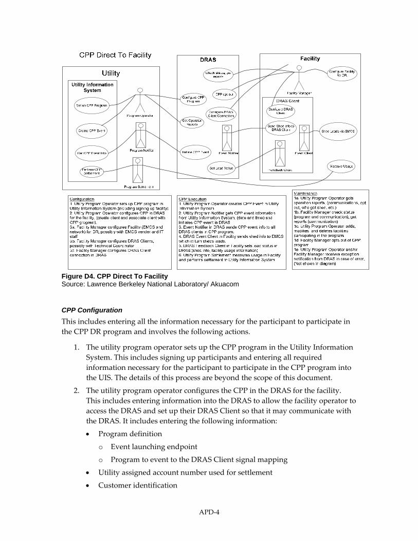
Figure D4. CPP Direct To Facility Source: Lawrence Berkeley National Laboratory/ Akuacom
CPP Configuration
This includes entering all the information necessary for the participant to participate in
the CPP DR program and involves the following actions.
1. The utility program operator sets up the CPP program in the Utility Information
System. This includes signing up participants and entering all required
information necessary for the participant to participate in the CPP program into
the UIS. The details of this process are beyond the scope of this document.
2. The utility program operator configures the CPP in the DRAS for the facility.
This includes entering information into the DRAS to allow the facility operator to
access the DRAS and set up their DRAS Client so that it may communicate with
the DRAS. It includes entering the following information:
Program definition
o Event launching endpoint
o Program to event to the DRAS Client signal mapping
Utility assigned account number used for settlement
Customer identification
APD‐4
Customer password
Geographic location
Grid location
3a. The facility manager configures the facility’s EMCS and network for DR, possibly
in conjunction with the EMCS vendor and IT staff. This could include
programming the EMCS to respond to DR events and shed or shift loads
appropriately. The details of this process are beyond the scope of this document.
3b. The facility manager configures DRAS Clients, possibly in conjunction with the
technical coordinator. DRAS Clients may take many forms, both in terms of
hardware and software. This step configures the DRAS Client so that it can
communicate with the Facilities systems that are responsible for managing the
loads. The details of this process are beyond the scope of this document.
3c. The facility manager configures DR program parameters and DRAS Client
connection in the DRAS. This step establishes the connection between the DRAS
Client and the DRAS. Typically this includes the following types of information:
Identification and password of the Customer participating in the program
Contact information, i.e. phone number, pager, email, etc.
DRAS Client communications parameters
o DRAS IP address
o identification
o password
o IP connection information
o polling frequency if polling the DRAS Client
Optionally ‐ Load reduction potential (per time block per level)
Exception parameters
Opt‐out dates
Note that this action is currently depicted as occurring in the DRAS, but depending
upon how this step is subsequently implemented in future OpenADR standards, this
may be performed in the DRAS Client and not in the DRAS.
CPP Execution
The actions to execute CPP events consist of the following steps:
1. The utility program operator creates the CPP event in the Utility Information
System. In this step a program operator schedules the CPP event in the Utility
Information System. The details of this process are beyond the scope of this
document.
APD‐5

2. The utility program notifier gets the CPP event information from the Utility
Information System and initiates the CPP event in the DRAS. The information
sent to the DRAS by the utility program notifier sub‐system includes:
Program type
Date and time of the event
Date and time issued
Geographic location
Customer list (account numbers)
3. The event notifier in the DRAS sends the CPP event information to all DRAS
Clients in the CPP program. The CPP event information sent to the DRAS Clients
includes:
Utility event information for Intelligent DRAS Clients
o Date and time of the event
o Date and time issued
o Geographic location (optional)
o Mode and pending signals
Mode signal levels for Simple DRAS Clients (e.g. normal, moderate, high)
Event pending signal for Simple DRAS Clients (e.g. yes/no, or simple
quantification of how far in advance notice is to be sent)
4. The DRAS Event Client for the facility sends shed or shift information to the
EMCS which in turn sheds loads. The details of this process are beyond the scope
of this document.
5. The DRAS Feedback Client for the facility sends the system load status to the
DRAS. This is a feedback mechanism that is used to record how the facility
responded to the DR event. It includes the following information:
Program identifier
Facility identifier
Date and time of the event (shed or shift)
Shed data in kW/kWh
Load reduction end uses (HVAC, lighting, etc.)
6. The utility program settlement measures usage in the facility and performs
settlement in the Utility Information System. How this process is done is beyond
the scope of this document.
CPP Maintenance
This scenario consists of a set of actions which are necessary to maintain the CPP
program. Unlike the configuration and execution scenarios this set of actions are less a
APD‐6

prescribed set of steps and more a set of possible actions that may be performed by the
various roles at unrelated times.
1a. The utility program operator gets the operation reports. The utility program
operator can get the following status information from the DRAS at any time:
Event status (for all participants)
o current outstanding events
Load reduction potential based upon all customers in program
(optional)
Feedback from DRAS Clients (for those that have optional feedback)
o event logs
1b. The facility manager checks the status. The utility program operator can get the
following status information from the DRAS at any time:
DRAS Client communications status
o current status
o last contact
o current signals levels
o current customer manual control levels (opt‐out)
o communication logs
o signal logs
o manual control logs
Event status (same as above)
1c. The utility program operator adds, modifies and deletes facilities participating in
the program. This is similar to the original configuration step.
1d. The facility manager opts out of the DR program. At any time, the facility
manager can opt‐out of the DR program on the DRAS. When in an opt‐out
condition, DR events are not propagated to the DRAS Client. The opt‐out can be
either for the entire program or a single event or a specific event‐mode (e.g.
normal, moderate, high)
1e. The utility program operator and/or the facility manager receives an exception
notification from the DRAS in case of an error (this is not shown in the diagram).
When an error condition occurs in the DRAS which may require some sort of
action by either the participant or the utility the DRAS will send a message to the
respective operators via email, voice or pager. Note that this alarming interface
does not cover exception conditions that are part of the DRAS operation and
managed by the DRAS operator, which are outside the scope of this document.
The type of exceptions covered by this interface includes:
DRAS Client communications failure.
APD‐7

D.2.1.2 CPP via Aggregator
In the actual CPP programs currently offered by PG&E, the aggregators do not typically
play a role. The following use cases envision how an aggregator might play a role with
the DRAS. It is very similar to the direct to facility use case. The use case diagram can be
seen in Figure D5.
Figure D5. CPP via Aggregator Source: Lawrence Berkeley National Laboratory/ Akuacom
CPP Configuration
This includes entering all the information necessary for the participant to participate in
the CPP DR program and involves the following actions.
1. The utility program operator sets up the CPP program in the Utility Information
System. This includes signing up participants and entering all required
information necessary for the participant to participate in the CPP program into
the UIS. The details of this process are beyond the scope of this document.
2. The utility program operator configures the CPP in the DRAS for the facility.
This includes entering information into the DRAS to allow the facility operator to
access the DRAS and set up their DRAS Client so that it may communicate with
the DRAS. It includes entering the following information:
APD‐8

Program definition
o Event launching endpoint
o Program to event to DRAS Client signal mapping
Utility assigned account number used for settlement
Customer identification
Customer password
Geographic location
Grid location
3a. The aggregator configures the facility (EMCS and network) for DR, possibly in
conjunction with the EMCS vendor and IT staff. The details of this process are
beyond the scope of this document.
3b. The aggregator configures the DRAS Clients, possibly in conjunction with the
technical coordinator. DRAS Clients may take many forms, both in terms of
hardware and software. This step configures the DRAS Client so that it can
communicate with the aggregator’s systems that are responsible for managing
the loads. The details of this process are beyond the scope of this document.
3c. The aggregator configures the DR program parameters and the DRAS Client
connection in the DRAS. This step establishes the connection between the DRAS
Client and the DRAS. Typically this includes the following types of information:
Identification and password of the Customer participating in the program.
Contact information, i.e. phone number, pager, email, etc.
DRAS Client communications parameters.
o DRAS IP address
o identification
o password
o IP connection information
o polling frequency if a polling the DRAS Client.
Optionally ‐ Load reduction potential (per time block per level)
Exception parameters.
Opt‐out dates
Note that this action is currently depicted as occurring within the DRAS, but
depending upon how this step is subsequently implemented in a future OpenADR
standards, this may be performed within the DRAS Client and not within the DRAS.
CPP Execution
The set of actions to execute CPP events include the following steps:
APD‐9

1. The utility program operator creates CPP event in the Utility Information
System. In this step a program operator schedules a CPP event in the Utility
Information System. The details of this process are beyond the scope of this
document.
2. The utility program notifier gets CPP event information from the Utility
Information System and initiates CPP event in the DRAS. The information sent to
the DRAS by the utility program notifier sub‐system includes the following
information:
Program type
Date and time of the event
Date and time issued
Geographic location
Customer list (account numbers)
3. The event notifier in the DRAS sends CPP event information to all DRAS Clients
in CPP program. The CPP event information sent to the DRAS Clients includes
the following:
Utility event information for Intelligent DRAS Clients
o Date and time of the event
o Date and time issued
o Geographic location (optional)
o Mode and pending signals
Mode signal levels for Simple DRAS Clients (e.g. normal, moderate, high)
Event pending signal for Simple DRAS Clients (e.g. yes/no, or simple
quantification of how far in advance notice is to be sent)
4. The DRAS Event Client for the facility sends shed or shift information to the
aggregator’s system which in turn causes the aggregator to shed or shift loads in
various facilities. How this process is done is beyond the scope of this document.
5. The DRAS Feedback Client for the aggregator’s system sends the system load
status to the DRAS. This is a feedback mechanism that is used to record how the
facility responded to the DR event. It includes the following information:
Program identifier
Facility identifier
Date and time of the event (shed or shift)
Shed data in kW/kWh
Load reduction end uses (HVAC, lighting, etc.)
APD‐10

6. The utility program settlement measures usage in the facility and performs
settlement in the Utility Information System. The details of this process are
beyond the scope of this document.
CPP Maintenance
This scenario consists of a set of actions which are necessary to maintain the CPP
program. Unlike the Configuration and Execution scenarios this set of actions are less a
prescribed set of steps and more a set of possible actions that may be performed by the
various roles at unrelated times.
1a. The utility program operator gets the operation reports. The utility program
operator can get the following status information from the DRAS at any time:
Event status (for all participants)
o current outstanding events
Load reduction potential based upon all customers in program
(optional)
Feedback from DRAS Clients (for those that have optional feedback)
o event logs
1b. The facility manager checks status. The utility program operator can get the
following status information from the DRAS at any time:
DRAS Client communications status
o current status
o last contact
o current signals levels
o current customer manual control levels (opt‐out)
o communication logs
o signal logs
o manual control logs
Event status (same as above)
1c. The utility program operator adds, modifies and deletes facilities participating in
the program. This is similar to the original configuration step.
1d. The aggregator opts out of the DR program. At any time, the aggregator or the
aggregator acting as facility manager can opt out of the DR program on the
DRAS. When there is an opt‐out condition, DR events are not propagated to the
DRAS Client. The opt‐out can be either for the entire program or a single event.
1e. The utility program operator and/or the aggregator operator receive an exception
notification from the DRAS in case of an error (this is not shown in the diagram).
When an error condition occurs in the DRAS which may require some sort of
action by either the participant or the utility the DRAS will send a message to the
APD‐11

respective operators via email, voice or pager. Note that this alarming interface
does not cover exception conditions that are part of the DRAS operation and
managed by the DRAS operator, which is outside the scope of this document.
The types of exceptions covered by this interface include:
DRAS Client communications failure.
D.2.2 Demand Bidding Program (DBP)
The Demand Bidding Program (DBP) is offered by PG&E. PG&E’s website,
http://www.pge.com/mybusiness/energysavingsrebates/demandresponse/dbp/, has the
following description of this program:
The (Automated) Demand Bidding Program (E‐DBP) pays an incentive to reduce
electric loads according to a voluntary bid made for a scheduled load reduction on
the following non‐holiday weekday. Under this program, participants receive a
credit equal to the product of the qualified kilowatt (kW) energy reduction and the
incentive price of up to $0.60/kWh.
How the Day‐Ahead Program Works
When the forecasted system reserve margins for the next day result in the California
Independent System Operator (CAISO) issuing an Alert Notice, or when the CAISO
day‐ahead forecasted peak demand is 43,000 megawatts (MW) or greater, or when
Pacific Gas and Electric Company (PG&E), in its sole opinion, forecasts that
resources will not be adequate, PG&E may request load reduction bids from
customers for the following non‐holiday weekday. Customers seeking to participate
in the E‐DBP can submit bids for a proposed level of curtailment.
Participating customers will have until 12:00 noon on the day before a proposed
curtailment event to submit bids via the ITRON’s Inter‐Act website. Upon
evaluation from Pacific Gas and Electric Company, customers will be notified of bid
acceptance after 4 p.m. of the same day. Unless a specific megawatt (MW) limit is
requested, PG&E will accept all bids. Participants must bid a minimum of two
consecutive hours throughout the day and must meet the minimum energy
reduction threshold of 50 kilowatts (kW) for single account and 200 kilowatts (kW)
for aggregated accounts.
Day‐Ahead Incentives
The Day‐Ahead E‐DBP incentives are calculated on an hourly basis, and will be
equal to the product of the qualified kW reduction for each hour a bid was accepted
and the incentive price of $0.50/kWh.
How the Day‐Of Program Works
When the CAISO issues any alert during the day reflecting stress on the system,
PG&E may implement an E‐DBP event for that same day. Customers have one hour
after a Day‐Of event has been issued to submit bids for a proposed level of
APD‐12

curtailment. Unless a specific megawatt (MW) limit is requested, PG&E will accept
all bids.
If a customer already has accepted‐bids for the Day‐Ahead program customers may
1) increase its bids for those hours that the Day‐Ahead and Day‐Of DBP events
coincide, and 2) submit new bids for those hours in the Day‐Of DBP event that were
not a part of the Day‐Ahead event. If no adjustments to the bid are made the
participation is automatically transferred to the Day‐Of program with the higher
incentive price.
Day‐Of Incentives
The Day‐Of E‐DBP incentives are calculated on an hourly basis, and will be equal to
the product of the qualified kW reduction for each hour a bid was accepted and the
incentive price of $0.60/kWh.
D.2.2.1 DBP Directly to Facilities
The following set of use cases concern CPP programs which are enacted directly with
participant facilities. The use case diagram can be seen in Figures D6 and D7.
Figure D6. DB Program Configuration Source: Lawrence Berkeley National Laboratory/ Akuacom
APD‐13

Figure D7. DBP Direct to Facility Source: Lawrence Berkeley National Laboratory/ Akuacom
DBP Configuration
This includes entering all the information necessary for the participant to participate in
the DBP DR program and involves the following actions.
1. The utility program operator sets up the DBP program in the Utility Information
System. This includes signing up participants and entering all the required
information necessary for the participant to participate in the DBP program into
the UIS. The details of this process are beyond the scope of this document.
2. The utility program operator configures the DBP in the DRAS for the facility.
This includes entering information into the DRAS to allow the facility operator to
access the DRAS and set up their DRAS Client so that it may communicate with
the DRAS. It includes entering the following information:
Program definition
APD‐14

o Event launching endpoint
o Program to event to DRAS Client signal mapping
Utility assigned account number used for settlement
Customer identification
Customer password
Geographic location
Grid location
3a. The facility manager configures the facility (EMCS and network) for DR, possibly
in conjunction with the EMCS vendor and IT staff. This could include
programming the EMCS to respond to DR events and shed or shift loads
appropriately. The details of this process are beyond the scope of this document.
3b. The facility manager configures the DRAS Clients, possibly in conjunction with
the technical coordinator. DRAS Clients may take many forms, both in terms of
hardware and software. This step configures the DRAS Client so that it can
communicate with the Facilities systems that are responsible for managing the
loads. The details of this process are beyond the scope of this document.
3c. The facility manager configures a standing bid in the DRAS. This is the bid that
will be automatically placed by the DRAS when a request for bids comes from
the utility. It includes the following:
Load reduction bids per time block (price and load amount)
3d. The facility manager configures the DR program parameters and DRAS Client
connection in the DRAS. This step establishes the connection between the DRAS
Client and the DRAS. Typically this includes the following types of information:
Identification and password of the Customer participating in the program.
Contact information, i.e. phone number, pager, email, etc.
DRAS Client communications parameters.
o DRAS IP address
o identification
o password
o IP connection information
o polling frequency if a polling DRAS Client.
Optionally–Load reduction potential (per time block per level)
Exception parameters.
Opt‐out dates
Note that this action is currently depicted as occurring in the DRAS, but depending
upon how this step is subsequently implemented in a future OpenADR standards,
this may be performed in the DRAS Client and not in the DRAS.
APD‐15

DBP Execution
The set of actions to execute DBP events include the following steps:
1. The utility program operator creates or schedules the DBP event in the Utility
Information System. The details of this process are beyond the scope of this
document.
2. The utility program notifier gets the DBP event information from the Utility
Information System and initiates a DBP event in the DRAS. The information sent
to the DRAS by the utility program notifier sub‐system includes the following
information:
Program type
Date and time of the event
Date and time issued
Geographic location
Customer list (account numbers)
Request For Bids (RFB) issue date and time
RFB close time
Price offered for load reduction per time block
3. The DRAS program notifier sends request for bid to the facility manager. This
notification typically comes in the form of an email, phone call or page.
4. The facility manager adjusts or cancels their current bid in the DRAS. This is an
optional step and allows the Manager to adjust their bid for that particular event. If
this step is not performed then the DRAS will submit the standing bid after some
period of time.
5. After time limit has expired the Bidding Proxy in the DRAS sets the current bid in
the Utility Information System. The information sent by the DRAS includes the
following:
Customer account number
Load reduction bids per time block
6. The utility program notifier gets accepted bids from the Utility Information System
and sets accepted bids in the DRAS. The accepted bids form the set of participants
that the DRAS will send DB shed or shift events to. The information concerning
accepted bids include:
Customer list (account number)
APD‐16

Accept or reject
Load reduction bids per time block (for verification)
7. The DRAS program notifier sends the acceptance notification to the facility manager.
The manager is notified of an accepted bid via phone, email, or page.
8. The event notifier in the DRAS sends the DBP event information to all DRAS Clients
whose bids were accepted. The DBP event information sent to the DRAS Clients
includes the following:
Utility event information for Intelligent DRAS Clients
o Date and time of the event
o Date and time issued
o Geographic location (optional)
o Mode and pending signals
Mode signal levels for Simple DRAS Clients (e.g. normal, moderate, high)
Event pending signal for Simple DRAS Clients (e.g. yes/no, or simple
quantification of how far in advance notice is to be sent)
9. The DRAS Event Client in the facility sends shed or shift information to the EMCS
which in turn causes loads to be shed or shift. How this process is done is beyond
the scope of this document.
10. The DRAS Feedback Client in the aggregator’s system sends the system load status
information to the DRAS. This is a feedback mechanism that is used to record how
the facility responded to the DR event. It includes the following information:
Program identifier
Facility identifier
Date and time of the event (shed or shift)
Shed data in kW/kWh
Load reduction end uses (HVAC, lighting, etc.)
Event Type (Day‐Ahead or Day‐Of)
11. The utility program settlement measures usage in the facility and performs
settlement in the Utility Information System. How this process is done is beyond the
scope of this document.
DBP Maintenance
This scenario consists of a set of actions which are necessary to maintain the DBP
program. Unlike the configuration and execution scenarios this set of actions are less a
prescribed set of steps and more a set of possible actions that may be performed by the
various roles at unrelated times.
1a. The utility program operator gets the operation reports. The utility program
operator can get the following status information from the DRAS at any time:
APD‐17

Event status (for all participants)
o current outstanding events
Load reduction potential based upon all customers in program
(optional)
Feedback from DRAS Clients (for those that have optional feedback)
o event logs
Bids and signal levels per time block for current events (for all participants,
indivually and grouped together)
1b. The facility manager checks status. The facility manager can get the following
status information from the DRAS at any time:
DRAS Client communications status
o current status
o last contact
o current signals levels
o current customer manual control levels (opt‐out)
o communication logs
o signal logs
o manual control logs
Event status (same as above)
Bids and signal levels per time block for current events
1c. The utility program operator adds, modifies or deletes facilities participating in
the program. This is similar to the original configuration step.
1d. The facility manager opts out of the DR program. At any time, the facility
manager can opt‐out of the DR program on the DRAS. When there is an opt‐out
condition, DR events are not propagated to the DRAS Client. The opt‐out can be
either for the entire program or a single event.
1e. The facility manager adjusts standing bid in the DRAS.
1f. The utility program operator and/or the facility manager receive an exception
notification from the DRAS in case of an error (this is not shown in the diagram).
When an error condition occurs in the DRAS which may require some sort of
action by either the participant or the utility the DRAS will send a message to the
respective operators via email, voice or pager. Note that this alarming interface
does not cover exception conditions that are part of the DRAS operation and
managed by the DRAS operator, which is outside the scope of this document.
The types of exceptions covered by this interface include:
DRAS Client Communications Failure
APD‐18

D.2.2.2 DBP via Third Party Aggregators
The following set of use cases concern DBP programs which are enacted with
aggregators. The use case diagram can be seen in Figure D8.
Figure D8. DBP with Aggregator Source: Lawrence Berkeley National Laboratory/ Akuacom
DBP Configuration
This includes entering all the information necessary for the participant to participate in
the DBP DR program and involves the following actions:
1. The utility program operator sets up the DBP program in the Utility Information
System. This includes signing up participants and entering all required
information necessary for the participant to participate in the DBP program into
the UIS. The details of this process are beyond the scope of this document.
2. The utility program operator configures the DBP in the DRAS for the facility.
This includes entering information into the DRAS to allow the facility operator to
APD‐19
access the DRAS and set up their DRAS Client so that it may communicate with
the DRAS. It includes entering the following information:
Program definition
o Event launching endpoint
o Program to event to DRAS Client signal mapping
Utility assigned account number used for settlement
Customer identification
Customer password
Geographic location
Grid location
3a. The aggregator configures their systems for DR. The details of this process are
beyond the scope of this document.
3b. The aggregator configures the DRAS Clients, possibly in conjunction with the
technical coordinator. DRAS Clients may take many forms, both in terms of
hardware and software. This step configures the DRAS Client so that it can
communicate with the aggregator systems that are responsible for managing the
loads. The details of this process are beyond the scope of this document.
3c. The aggregator sets their standing bid in the DRAS. This is the bid that will be
automatically placed by the DRAS when a request for bids comes from the
utility. It includes the following:
Load reduction bids per time block (price and load amount)
3d. The aggregator configures the DR program parameters and the DRAS Client
connection in the DRAS. This step establishes the connection between the DRAS
Client and the DRAS. Typically this includes the following types of information:
Identification and password of the Customer participating in the program.
Contact information, i.e. phone number, pager, email, etc.
DRAS Client communications parameters.
o DRAS IP address
o identification
o password
o IP connection information
o polling frequency if a polling DRAS Client.
Optionally ‐ Load reduction potential (per time block per level)
Exception parameters.
Opt‐out dates
APD‐20
Note that this action is currently depicted as occurring in the DRAS, but depending
upon how this step is subsequently implemented in a future OpenADR standards,
this may be performed in the DRAS Client and not in the DRAS.
DBP Execution
The set of actions to execute DBP events include the following steps:
1. The utility program operator creates the DBP event in the Utility Information
System. In this step a program operator schedules a DBP event in the Utility
Information System. The details of this process are beyond the scope of this
document.
2. The utility program notifier gets DBP event information from the Utility
Information System and initiates the DBP event in the DRAS. The information
sent to the DRAS by the utility program notifier sub‐system includes the
following information:
Program type
Date and time of the event
Date and time issued
Geographic location
Customer list (account numbers)
Request For Bids (RFB) issue date and time
RFB close time
Price offered for load reduction per time block
3. The DRAS program notifier sends a request for bid to the aggregator. This
notification typically comes in the form of an email, phone call or page.
4. The aggregator adjusts or cancels their current bid in the DRAS. This is an
optional step and allows the Manager to adjust their bid for that particular event.
If this step is not performed then the DRAS will submit the standing bid after
some pre‐set period of time.
5. After the time limit has expired, the Bidding Proxy in the DRAS sets the current
bid in the Utility Information System. The information sent by the DRAS
includes the following:
Customer account number
Load reduction bids per time block
6. The utility program notifier gets accepted bids from the Utility Information
System and sets accepted bids in the DRAS. The accepted bids form the set of
participants that the DRAS will send DB shed or shift events to. The information
concerning accepted bids include:
Customer list (account number)
APD‐21

Accept or reject
Load reduction bids per time block (for verification)
7. The DRAS program notifier sends the acceptance notification to the facility
manager. The manager is notified of an accepted bid via phone, email, or page.
8. The event notifier in the DRAS sends DBP event information to all DRAS Clients
whose bids were accepted. The DBP event information sent to the DRAS Clients
includes the following:
Utility event information for Intelligent DRAS Clients
o Date and time of the event
o Date and time issued
o Geographic location (optional)
o Mode and pending signals
Mode signal levels for Simple DRAS Clients (e.g. normal, moderate, high)
Event pending signal for Simple DRAS Clients (e.g. yes/no, or simple
quantification of how far in advance notice is to be sent)
9. The DRAS Event Client for the facility sends shed or shift information to the
aggregator’s system which in turn causes the aggregator to shed or shift loads in
various facilities. How this process is done is beyond the scope of this document.
10. The DRAS Feedback Client for the aggregator’s system sends the system load
status to the DRAS. This is a feedback mechanism that is used to record how the
facility responded to the DR event. It includes the following information:
Program identifier
Facility identifier
Date and time of the event (shed or shift)
Shed data in kW/kWh
Load reduction end uses (HVAC, lighting, etc.)
Event Type (Day‐Ahead or Day‐Of)
11. The utility program settlement measures usage in the facility and performs
settlement in Utility Information System. How this process is done is beyond the
scope of this document.
DBP Maintenance
This scenario consists of a set of actions which are necessary to maintain the DBP
program. Unlike the Configuration and Execution scenarios this set of actions are less a
prescribed set of steps and more a set of possible actions that may be performed by the
various roles at unrelated times.
1a. The utility program operator gets operation reports. The utility program
operator can get the following status information from the DRAS at any time:
APD‐22

Event status (for all participants)
o current outstanding events
Load reduction potential based upon all customers in program
(optional)
Feedback from DRAS Clients (for those that have optional feedback)
o event logs
Bids and signal levels per time block for current events (for all participants,
indivually and grouped together)
1b. The aggregator checks status. The aggregator can get the following status
information from the DRAS at any time:
DRAS Client communications status
o current status
o last contact
o current signals levels
o current customer manual control levels (opt‐out)
o communication logs
o signal logs
o manual control logs
Event status (same as above)
Bids and signal levels per time block for current events
1c. The utility program operator adds, modifies and deletes facilities participating in
the program. This is similar to the original configuration step.
1d. The aggregator opts out of the DR program. At any time, the aggregator or the
aggregator acting as facility manager can opt out of the DR program on the
DRAS. When there is an opt‐out condition, DR events are not propagated to the
DRAS Client. The opt‐out can be either for the entire program or a single event.
1e. The aggregator adjusts standing bid in the DRAS.
1f. The utility program operator and/or the aggregator receive an exception
notification from the DRAS in case of an error (this is not shown in the diagram).
When an error condition occurs in the DRAS which may require some sort of
action by either the participant or the utility the DRAS will send a message to the
respective operators via email, voice or pager. Note that this alarming interface
does not cover exception conditions that are part of the DRAS operation and
managed by the DRAS operator, which is outside the scope of this document.
The types of exceptions covered by this interface include:
DRAS Client communications failure.
D.2.3 Capacity Bidding Program (CBP)
APD‐23

The Capacity Bidding Program (CBP) is offered by PG&E. PG&E’s website,
http://www.pge.com/mybusiness/energysavingsrebates/demandresponse/cbp/, provides
the following description of this program:
The Capacity Bidding Program (E‐CBP) is a mandatory program that pays you a
monthly incentive to reduce your load to a pre‐determined amount when an electric
resource generation facility reaches or exceeds heat rates of 15,000 BTU/kWh. E‐CBP
operates seasonally from May 1 to October 31.
How It Works
To participate in the program, you must simply identify which of the two option best
suites you and your business line — Day Ahead or Day Of program hours are 11:00
a.m. to 7:00 p.m., Monday through Friday excluding Pacific Gas and Electric
Company holidays and weekends.
Day‐Ahead Curtailment
Maximum of one event per day
Will not exceed 24 events per month
Notices will be issued by 3:00 p.m. on the business day before the operation day.
Directly-Enrolled Customer in Day-Ahead Option
Product May June July August September October
1-4 $0.00/kW $2.97/kW $12.48/kW $17.26/kW $10.64/kW $0.00/kW
2-6 $0.00/kW $2.97/kW $12.48/kW $17.26/kW $10.64/kW $0.00/kW
4-8 $0.00/kW $2.97/kW $12.48/kW $17.26/kW $10.64/kW $0.00/kW
Aggregators in Day-Ahead Option
Product May June July August September October
1-4 $0.00/kW $3.71/kW $15.60/kW $21.57/kW $13.30/kW $0.00/kW
2-6 $0.00/kW $3.71/kW $15.60/kW $21.57/kW $13.30/kW $0.00/kW
4-8 $0.00/kW $3.71/kW $15.60/kW $21.57/kW $13.30/kW $0.00/kW
Day‐Of Curtailment
Maximum of one event per day
APD‐24
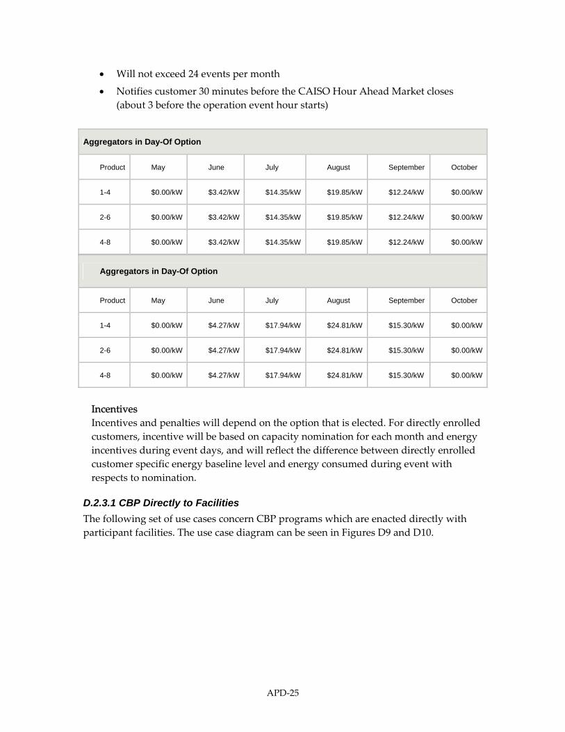
Will not exceed 24 events per month
Notifies customer 30 minutes before the CAISO Hour Ahead Market closes
(about 3 before the operation event hour starts)
Aggregators in Day-Of Option
Product May June July August September October
1-4 $0.00/kW $3.42/kW $14.35/kW $19.85/kW $12.24/kW $0.00/kW
2-6 $0.00/kW $3.42/kW $14.35/kW $19.85/kW $12.24/kW $0.00/kW
4-8 $0.00/kW $3.42/kW $14.35/kW $19.85/kW $12.24/kW $0.00/kW
Aggregators in Day-Of Option
Product May June July August September October
1-4 $0.00/kW $4.27/kW $17.94/kW $24.81/kW $15.30/kW $0.00/kW
2-6 $0.00/kW $4.27/kW $17.94/kW $24.81/kW $15.30/kW $0.00/kW
4-8 $0.00/kW $4.27/kW $17.94/kW $24.81/kW $15.30/kW $0.00/kW
Incentives
Incentives and penalties will depend on the option that is elected. For directly enrolled
customers, incentive will be based on capacity nomination for each month and energy
incentives during event days, and will reflect the difference between directly enrolled
customer specific energy baseline level and energy consumed during event with
respects to nomination.
D.2.3.1 CBP Directly to Facilities
The following set of use cases concern CBP programs which are enacted directly with
participant facilities. The use case diagram can be seen in Figures D9 and D10.
APD‐25

Figure D9 CBP Program Configuration Source: Lawrence Berkeley National Laboratory/ Akuacom
APD‐26

Figure D10. CBP Direct to Facility Source: Lawrence Berkeley National Laboratory/ Akuacom
CBP Configuration
This includes entering all the information necessary for the participant to participate in
the DBP DR program and involves the following actions.
1. The utility program operator sets up the DBP program in the Utility Information
System. This includes signing up participants and entering all required
information necessary for the participant to participate in the DBP program into
the UIS. The details of this process are beyond the scope of this document.
2. The utility program operator configures the DBP in the DRAS for the facility.
This includes entering information into the DRAS to allow the facility operator to
access the DRAS and set up their DRAS Client so that it may communicate with
the DRAS. It includes entering the following information:
Program definition
Event launching endpoint
Program to event to DRAS Client signal mapping
APD‐27

Utility assigned account number used for settlement
Customer identification
Customer password
Geographic location
Grid location
3a. The facility manager configures the facility’s EMCS and network for DR, possibly
in conjunction with the EMCS vendor and IT staff. This could include
programming the EMCS to respond to DR events and shed or shift loads
appropriately. The details of this process are beyond the scope of this document.
3b. The facility manager configures the DRAS Clients, possibly in conjunction with
the technical coordinator. DRAS Clients may take many forms, both in terms of
hardware and software. This step configures the DRAS Client so that it can
communicate with the Facilities systems that are responsible for managing the
loads. The details of this process are beyond the scope of this document.
3c. The facility manager sets the standing bid in the DRAS. This is the bid that will
be automatically placed by the DRAS when a request for bids comes from the
Utility. It includes the following:
Load reduction bids per time block (price and load amount)
3d. The facility manager configures the DR program parameters and the DRAS
Client connection in the DRAS. This step establishes the connection between the
DRAS Client and the DRAS. Typically this includes the following types of
information:
Identification and password of the Customer participating in the program
Contact information, i.e. phone number, pager, email, etc.
DRAS Client communications parameters
o DRAS IP address
o identification
o password
o IP connection information
o polling frequency if a polling DRAS Client
Optionally–Load reduction potential (per time block per level)
Exception parameters
Opt‐out dates
Note that this action is currently depicted as occurring in the DRAS, but depending
upon how this step is subsequently implemented in a future OpenADR standards,
this may be performed in the DRAS Client and not in the DRAS.
APD‐28
CBP Execution
CBP includes a bidding process, but unlike DBP the request for bids are not linked
directly to the shedding events. The bidding process and the shedding process are two
distinct sets of steps. Because of this de‐coupling it is unlikely that the DRAS would play
a useful role in automating the bidding process, but it is still documented here for
completeness.
The bidding process includes the following steps:
1. The utility program operator creates the CBP Bidding event in the Utility
Information System. In this step a program operator schedules the CBP Bidding
event in the Utility Information System. The details of this process are beyond
the scope of this document.
2. The utility program notifier gets the CBP bidding event information from the
Utility Information System and initiates the CBP Request for bids in the DRAS.
The information sent to the DRAS by the utility program notifier sub‐system
includes the following information:
Program type
Date and time of the event
Date and time issued
Geographic location
Customer list (account numbers)
Request For Bids (RFB) issue date and time
RFB close time
Price offered for load reduction per time block
3. The DRAS program notifier sends the request for bid to the facility manager.
This notification typically comes in the form of an email, phone call or page.
4. The facility manager adjusts or cancels their current bid in the DRAS. This is an
optional step and allows the Manager to adjust their bid for that particular event.
If this step is not performed, the DRAS will submit the standing bid after a pre‐
set period of time.
5. After the pre‐bid time limit has expired, the Bidding Proxy in the DRAS sets the
current bid in the Utility Information System. The information sent by the DRAS
includes the following:
Customer account number
Load reduction bids per time block
The shedding process includes the following steps:
APD‐29

1. The utility program operator creates the CBP Shed event in the Utility
Information System. In this step a program operator schedules the CBP Shed
event in the Utility Information System. The details of this process are beyond
the scope of this document.
2. The utility program notifier gets the accepted bids from the Utility Information
System and initiates the CB Shed in the DRAS. The accepted bids form the set of
participants that the DRAS will send CB shed or shift events to. The information
concerning accepted bids includes:
Customer list (account number)
Accept or reject
Load reduction bids per time block (for verification)
3. The DRAS program notifier sends the acceptance notification to the facility
manager. The manager is notified of an accepted bid via phone, email, or page.
4. The event notifier in the DRAS sends the CB event information to all the DRAS
Clients whose bids were accepted. The DBP event information sent to the DRAS
Clients includes the following information:
Utility event information for Intelligent DRAS Clients
o Date and time of the event
o Date and time issued
o Geographic location (optional)
o Mode and pending signals
Mode signal levels for Simple DRAS Clients (e.g. normal, moderate, high)
Event pending signal for Simple DRAS Clients (e.g. yes/no, or simple
quantification of how far in advance notice is to be sent)
5. The DRAS Event Client for the facility sends the shed or shift information to the
EMCS which in turn causes loads to be shed or shift in related facilities. How this
process is done is beyond the scope of this document.
6. The DRAS Feedback Client for the participant facility sends the system load
status information to the DRAS. This is a feedback mechanism that is used to
record how the facility responded to the DR event. It includes the following
information:
Program identifier
Facility identifier
Date and time of the event (shed or shift)
Shed data in kW/kWh
Load reduction end uses (HVAC, lighting, etc.)
Event Type (Day‐Ahead or Day‐Of)
APD‐30

7. The utility program settlement measures usage in the facility and performs
settlement in the Utility Information System. How this process is done is beyond
the scope of this document.
CBP Maintenance
This scenario consists of a set of actions which are necessary to maintain the DBP
program. Unlike the Configuration and Execution scenarios this set of actions are less a
prescribed set of steps and more a set of possible actions that may be performed by the
various roles at unrelated times.
1a. The utility program operator gets the operation reports. The utility program
operator can get the following status information from the DRAS at any time:
Event status (for all participants)
o current outstanding events
Load reduction potential based upon all customers in program
(optional)
Feedback from DRAS Clients (for those that have optional feedback)
o event logs
Bids and signal levels per time block for current events (for all participants,
indivually and grouped together)
1b. The facility manager checks status. The facility manager can get the following
status information from the DRAS at any time:
DRAS Client communications status
o Current status
o Last contact
o Current signals levels
o Current customer manual control levels (opt‐out)
o Communication logs
o Signal logs
o Manual control logs
Event status (same as above)
Bids and signal levels per time block for current events
1c. The utility program operator adds, modifies or deletes facilities participating in
the program. This is similar to the original configuration step.
1d. The facility manager opts out of the DR program. At any time, the facility
manager can opt out of the DR program on the DRAS. When there is an opt‐out
condition, DR events are not propagated to the DRAS Client. The opt‐out can be
either for the entire program or a single event.
1e. The facility manager adjusts their standing bid in the DRAS.
APD‐31

1f. The utility program operator and/or the facility manager receive an exception
notification from the DRAS in case of an error (this is not shown in the diagram).
When an error condition occurs in the DRAS which may require some sort of
action by either the participant or the utility the DRAS will send a message to the
respective operators via email, voice or pager. Note that this alarming interface
does not cover exception conditions that are part of the DRAS operation and
managed by the DRAS operator, which is outside the scope of this document.
The types of exceptions covered by this interface include:
DRAS Client communications failure.
D.2.3.2 CBP via Aggregators
The following set of use cases concern CBP programs which are enacted with
aggregators. The use case diagram based on difference configurations can be seen in
Figures D10 and D11.
Figure D11. CBP Direct to Facility Source: Lawrence Berkeley National Laboratory/ Akuacom
APD‐32

CBP Configuration
This includes entering all the information necessary for the participant to participate in
the DBP DR program and involves the following actions:
1. The utility program operator sets up the DBP program in the Utility Information
System. This includes signing up participants and entering all required
information necessary for the participant to participate in the DBP program into
the UIS. The details of this process are beyond the scope of this document.
2. The utility program operator configures the DBP in the DRAS for the facility.
This includes entering information into the DRAS to allow the facility operator to
access the DRAS and set up their DRAS Client so that it may communicate with
the DRAS. It includes entering the following information:
Program definition
o Event launching endpoint
o Program to event to DRAS Client signal mapping
Utility assigned account number used for settlement
Customer identification
Customer password
Geographic location
Grid location
3a. The aggregator configures their systems for DR. The details of this process are
beyond the scope of this document.
3b. The aggregator configures the DRAS Clients, possibly in conjunction with the
technical coordinator. DRAS Clients may take many forms, both in terms of
hardware and software. This step configures the DRAS Client so that it can
communicate with the aggregator systems that are responsible for managing the
loads. The details of this process are beyond the scope of this document.
3c. The aggregator sets a standing bid in the DRAS. This is the bid that will be
automatically placed by the DRAS when a request for bids comes from the
utility. It includes the following:
Load reduction bids per time block (price and load amount)
3d. The aggregator configures DR program parameters and DRAS Client connection
in the DRAS. This step establishes the connection between the DRAS Client and
the DRAS. Typically this includes the following types of information:
Identification and password of the Customer participating in the program
Contact information, i.e. phone number, pager, email, etc.
APD‐33

DRAS Client communications parameters
o DRAS IP address
o identification
o password
o IP connection information
o polling frequency if a polling DRAS Client
Optionally ‐ Load reduction potential (per time block per level)
Exception parameters
Opt‐out dates
Note that this action is currently depicted as occurring in the DRAS, but depending
upon how this step is subsequently implemented in a future OpenADR standards,
this may be performed in the DRAS Client and not in the DRAS.
CBP Execution
CBP includes a bidding process, but unlike DBP the request for bids are not linked
directly to the shedding events. Therefore the bidding process and the shedding process
are two distinct sets of steps. Because of this de‐coupling it is unlikely that the DRAS
would play a useful role in automating the bidding process, but it is documented here
for completeness.
The bidding process includes the following steps:
1. The utility program operator creates the CBP Bidding event in the Utility
Information System. In this step a program operator schedules a CBP Bidding
event in the Utility Information System. The details of this process are beyond
the scope of this document.
2. The utility program notifier gets the CBP bidding event information from the
Utility Information System and initiates the CBP Request for bids in the DRAS.
The information sent to the DRAS by the utility program notifier sub‐system
includes the following information:
Program type
Date and time of the event
Date and time issued
Geographic location
Customer list (account numbers)
Request For Bids (RFB) issue date and time
RFB close time
Price offered for load reduction per time block
APD‐34

3. The DRAS program notifier sends the request for bid to the aggregator. This
notification typically comes in the form of an email, phone call or page.
4. The aggregator adjusts or cancels the current bid in the DRAS. This is an optional
step and allows the Manager to adjust their bid for that particular event. If this
step is not performed then the DRAS will submit the standing bid after some pre‐
set period of time.
5. After the pre‐bid time limit has expired, the Bidding Proxy in the DRAS sets the
current bid in the Utility Information System. The information sent by the DRAS
includes the following:
Customer account number
Load reduction bids per time block
The shedding process includes the following steps:
1. The utility program operator creates the CBP Shed event in the Utility
Information System. In this step a program operator schedules a CBP Shed event
in the Utility Information System. The details of this process are beyond the
scope of this document.
2. The utility program notifier gets accepted bids from the Utility Information
System and initiates the CBP Shed in the DRAS. The accepted bids form the set of
participants that the DRAS will send the CB shed or shift events to. The
information concerning accepted bids include:
Customer list (account number)
Accept or reject
Load reduction bids per time block (for verification)
3. The DRAS program notifier sends the acceptance notification to the aggregator. The
aggregator operator is notified of an accepted bid via phone, email, or page.
4. The event notifier in the DRAS sends the CBP event information to all DRAS
Clients whose bids were accepted. The CBP event information sent to the DRAS
Clients includes:
Utility event information for Intelligent DRAS Clients
o Date and time of the event
o Date and time issued
o Geographic location (optional)
o Mode and pending signals
Mode signal levels for Simple DRAS Clients (e.g. normal, moderate, high)
Event pending signal for Simple DRAS Clients (e.g. yes/no, or simple
quantification of how far in advance notice is to be sent)
APD‐35

5. The DRAS Event Client for the facility sends shed or shift information to the
aggregator’s system which in turn causes the aggregator to shed or shift loads in
various facilities. How this process is done is beyond the scope of this document.
6. The DRAS Feedback Client in the aggregator’s system sends the system load
status to the DRAS. This is a feedback mechanism that is used to record how the
facility responded to the DR event. It includes the following information:
Program identifier
Facility identifier
Date and time of the event (shed or shift)
Shed data in kW/kWh
Load reduction end uses (HVAC, lighting, etc.)
Event Type (Day‐Ahead or Day‐Of)
7. The utility program settlement measures usage in the facility and performs
settlement in the Utility Information System. The details of this process are
beyond the scope of this document.
CBP Maintenance
This scenario consists of a set of actions which are necessary to maintain the DBP
program. Unlike the Configuration and Execution scenarios this set of actions are less a
prescribed set of steps and more a set of possible actions that may be performed by the
various roles at unrelated times.
1a. The utility program operator gets the operation reports. The utility program
operator can get the following status information from the DRAS at any time:
Event status (for all participants)
o current outstanding events
Load reduction potential based upon all customers in program
(optional)
Feedback from DRAS Clients (for those that have optional feedback)
o event logs
Bids and signal levels per time block for current events (for all participants,
indivually and grouped together)
1b. The aggregator checks status. The aggregator can get the following status
information from the DRAS at any time:
DRAS Client communications status
o current status
o last contact
o current signals levels
o current customer manual control levels (opt‐out)
APD‐36

o communication logs
o signal logs
o manual control logs
Event status (same as above)
Bids and signal levels per time block for current events
1c. The utility program operator adds, modifies or deletes facilities participating in
the program. This is similar to the original configuration step.
1d. The aggregator opts out of the DR program. At any time, the aggregator or the
aggregator acting as facility manager can opt out of the DR program on the
DRAS. When there is an opt‐out condition, DR events are not propagated to the
DRAS Client. The opt‐out can be either for the entire program or a single event.
1e. The aggregator adjusts their standing bid in the DRAS.
1f. The utility program operator and/or the aggregator receive an exception
notification from the DRAS in case of an error (this is not shown in the diagram).
When an error condition occurs in the DRAS which may require some sort of
action by either the participant or the utility, the DRAS will send a message to
the respective operators via email, voice or pager. Note that this alarming
interface does not cover exception conditions that are part of the DRAS operation
and managed by the DRAS operator, which is outside the scope of this
document. The types of exceptions covered by this interface include:
DRAS Client communications failure.
D.2.4 Base Interruptible Program (BIP)
The Base Interruptible Program (BIP) is offered by PG&E. PG&E’s website,
http://www.pge.com/mybusiness/energysavingsrebates/demandresponse/baseinterrupti
ble/, provides the following description of this program:
The Base Interruptible Program, or E‐BIP, is a program that pays to reduce your
electricity consumption to a pre‐determined amount when the California
Independent System Operator (CAISO) issues a load curtailment notice or in the
event of a local reliability emergency. There are two separate options for
participation. The mandatory option (option A) gives participating customers a
monthly payment for committing to reduce electricity demand to a predetermined
point when called upon. The voluntary option (option B) pays customers a fixed
amount per kilowatt reduced during a curtailment event.
How It Works
To participate in the program, participants must identify a designated load, or ʺfirm
service levelʺ, below your average peak demand. To participate, you must set a firm
service level at least 15 percent of your highest monthly maximum load with a
minimum designated load of 100 kW. New participants must elect one of two
available options.
APD‐37

Option A:
Gives the customer a 30 minute notification prior to mandatory curtailment of
load exceeding the established firm service level.
Monthly participation incentives are determined by the Potential Load
Reduction as calculated by the difference between the customer’s average
monthly seasonal demand and the designated firm service level.
Monthly incentives are determined by the following table:
Potential Load reduction Monthly Incentive
500 kW and below $8.00 per kW
501 kW–1,000 kW $8.50 per kW
1,001 kW and above $9.00 per kW
Failure to reduce loads during an event will result in a $6.00 charge per kilowatt
hour for energy use over the firm service level.
Option B:
Gives the customer a four‐hour notification and $0.60 per kWh incentive for a
qualifying load reduction during the curtailment event.
To qualify for the incentive, customers must reduce load to within 15% of the
designated firm service level.
There is no penalty for failing to reduce loads during an event.
To participate, you must commit to curtail: At least 15 percent of your average
monthly load or a minimum of 100 kW, whichever is greater
E‐BIP curtailment events are limited to:
Option A: A maximum of one event per day and four hours per event. The program
will not exceed 10 events per month, or 120 hours per calendar year.
Option B: There are no event limits on this voluntary option.
Aggregators
A customer may enroll directly with Pacific Gas and Electric Company or with a
third‐party aggregator. An aggregator is an entity appointed by a customer, to act on
behalf of the customer with respect to all aspects of the program, including receipt of
notices, receipt of incentive payments, and payment of penalties.
D.2.4.1 BIP Directly to Facilities
The following set of use cases concern BIP programs which are enacted directly with
participant facilities. The use case diagram can be seen in Figure D12.
APD‐38

Figure D12. BIP Direct to Facility Source: Lawrence Berkeley National Laboratory/ Akuacom
BIP Configuration
This includes entering all the information necessary for the participant to participate in
the BIP DR program and involves the following actions.
1. The utility program operator sets up the BIP program in the Utility Information
System. This includes signing up participants and entering all required
information necessary for the participant to participate in the BIP program into
the UIS. The details of this process are beyond the scope of this document.
2. The utility program operator configures the BIP in the DRAS for the facility. This
includes entering information into the DRAS to allow the facility operator to
access the DRAS and set up their DRAS Client so that it may communicate with
the DRAS. It includes entering the following information:
Program definition
o Event launching endpoint
o Program to event to DRAS Client signal mapping
APD‐39
Utility assigned account number used for settlement
Customer identification
Customer password
Geographic location
Grid location
3a. The facility manager configures the facility’s EMCS and network for DR, possibly
in conjunction with the EMCS vendor and IT staff. This could include
programming the EMCS to respond to DR events and shed or shift loads
appropriately. The details of this process are beyond the scope of this document.
3b. The facility manager configures DRAS Clients, possibly in conjunction with the
technical coordinator. DRAS Clients may take many forms, both in terms of
hardware and software. This step configures the DRAS Client so that it can
communicate with the Facility’s systems that are responsible for managing the
loads. The details of this process are beyond the scope of this document.
3c. The facility manager configures the DR program parameters and DRAS Client
connection in the DRAS. This step establishes the connection between the DRAS
Client and the DRAS. Typically this includes the following types of information:
Identification and password of the Customer participating in the program.
Contact information, i.e. phone number, pager, email, etc.
DRAS Client communications parameters
o DRAS IP address
o identification
o password
o IP connection information
o polling frequency if a polling DRAS Client
Optionally–Load reduction potential (per time block per level)
Exception parameters
Opt‐out dates
Note that this action is currently depicted as occurring in the DRAS, but depending
upon how this step is subsequently implemented in a future OpenADR standards,
this may be performed in the DRAS Client and not in the DRAS.
BIP Execution
The set of actions needed to execute BIP events include the following steps:
a. The utility program operator creates the BIP event in the Utility Information
System. In this step a program operator schedules a BIP event in the Utility
Information System. The details of this process are beyond the scope of this
document.
APD‐40

b. The utility program notifier gets the BIP event information from the Utility
Information System and initiates the BIP event in the DRAS. The information
sent to the DRAS by the utility program notifier sub‐system includes the
following information:
Program type
Date and time of the event
Date and time issued
Geographic location
Customer list (account numbers)
c. The event notifier in the DRAS sends the BIP event information to all DRAS
Clients in BIP program. The BIP event information sent to the DRAS Clients
includes the following:
Utility event info for Intelligent DRAS Clients
o Date and time of the event
o Date and time issued
o Geographic location (optional)
o Mode and pending signals
Mode signal levels for Simple DRAS Clients (e.g. normal, moderate, high)
Event pending signal for Simple DRAS Clients (e.g. yes/no, or simple
quantification of how far in advance notice is to be sent)
d. The DRAS Event Client for the facility sends shed or shift information to the
EMCS which in turn sheds loads. How this process is done is beyond the scope
of this document.
e. The DRAS Feedback Client for the facility sends the system load status to the
DRAS. This is a feedback mechanism that is used to record how the facility
responded to the DR event. It includes the following information:
Program identifier
Facility identifier
Date and time of the event (shed or shift)
Shed data in kW/kWh
Load reduction end uses (HVAC, lighting, etc.)
Event Type (Day‐Ahead or Day‐Of)
f. The utility program settlement measures usage in the facility and performs
settlement in the Utility Information System. How this process is done is beyond
the scope of this document.
APD‐41

BIP Maintenance
This scenario consists of a set of actions which are necessary to maintain the BIP
program. Unlike the Configuration and Execution scenarios this set of actions are less a
prescribed set of steps and more a set of possible actions that may be performed by the
various roles at unrelated times.
1a. The utility program operator gets the operation reports. The utility program
operator can get the following status information from the DRAS at any time:
Event status (for all participants)
o current outstanding events
Load reduction potential based upon all customers in program
(optional)
Feedback from DRAS Clients (for those that have optional feedback)
o event logs
1b. The facility manager checks the status. The utility program operator can get the
following status information from the DRAS at any time:
DRAS Client communications status
o Current status
o Last contact
o Current signals levels
o Current customer manual control levels (opt‐out)
o Communication logs
o Signal logs
o Manual control logs
Event status (same as above)
1c. The utility program operator adds, modifies or deletes facilities participating in
the program. This is similar to the original configuration step.
1d. The facility manager opts out of the DR program. At any time, the facility
manager can opt out of the DR program on the DRAS. When there is an opt‐out
condition, DR events are not propagated to the DRAS Client. The opt‐out can be
either for the entire program or a single event.
1e. The utility program operator and/or the facility manager receive an exception
notification from the DRAS in case of an error (this is not shown in the diagram).
When an error condition occurs in the DRAS which may require some sort of
action by either the participant or the utility the DRAS will send a message to the
respective operators via email, voice or pager. Note that this alarming interface
does not cover exception conditions that are part of the DRAS operation and
managed by the DRAS operator, which is outside the scope of this document.
The types of exceptions covered by this interface include:
APD‐42

DRAS Client communications failure.
D.2.4.2 BIP via Third Party Aggregators
The following use cases envision how an aggregator might play a role with the DRAS
for BIP. This is depicted in Figure D13. It is very similar to the direct to the facility use
case.
DRAS
Program Operator
Facility
Utility Information
System
Initiate BIP Event
Configure BIPProgram
Measure Usage
Configuration1. Utility Program Operator sets up BIP program in Utility Information System (including signing up aggregator)2. Utility Program Operator configures BIP in DRAS for the aggregator. (create client and associate client with BIP grogram).3a. Aggregator Operator configures Facilities (possibly EMCS and network) for DR, possibly with EMCS vendors and IT staff.3b. Aggregator Operator configures DRAS Clients, possibly with Technical Coordinator.3c. Aggregator Operator configures DRAS Client connection in DRAS.
BIP Execution1. Utility Program Operator creates BIP Event in Utility Information System .2. Utility Program Notifier gets BIP event information from Head End. (date and time) and initiates BIP event in DRAS3. Event Notifier in DRAS sends shed info to DRAS clients the Aggregator Information System.5. DRAS Event Client notifies other Aggregator systems (unknown and out of scope of this discussion) which in turn causes Aggregator to shed loads in various facilities.6. DRAS Feedback Client in Aggregator Information System sets load status in DRAS (which facilities shed, facility usage information)7. Utility Program Settlement of the Utility measures usage in Facilities and performs settlement in Utility Information System.
Get OperatorReports
Maintenance1a. Utility Program Operator gets operation reports. (communications, opt out, who got shed, etc.)1b. Aggregator Operatorchecks status (program and communication), get reports (communication)1c. Utility Program Operator adds, modifies, and deletes facilities participating in the program.1d. Aggregator opts out of BIP program.1e. Utility Program Operator and/or Aggregator Operator receives exception notification from DRAS in case of error. (Not shown in diagram)
BIP via Aggregator
Aggregator Operator
Check status, getreports
Set up BIP Program
Get BIP Event Info
Perform BIPSettlement
Create BIP Event
BIP opt out
Utility
Aggregator Information System
Set Load Status
DRAS Client
Configure DRASClient
Send Shed Info toDRAS Client
Get Load Status
Shed Loads
Configure DRASClient Connection
Program Notifier
Program Settlement
Event Notifier
Event Client
Feedback Client
Configure Facilityfor Auto DR
Figure D13. BIP via Aggregator Source: Lawrence Berkeley National Laboratory/ Akuacom
BIP Configuration
This includes entering all the information necessary for the participant to participate in
the BIP DR program and involves the following actions.
1. The utility program operator sets up the BIP program in the Utility Information
System. This includes signing up participants and entering all required
information necessary for the participant to participate in the BIP program into
the UIS. The details of this process are beyond the scope of this document.
2. The utility program operator configures the BIP in the DRAS for the facility. This
includes entering information into the DRAS to allow the facility operator to
access the DRAS and set up their DRAS Client so that it may communicate with
the DRAS. It includes entering the following information:
APD‐43

Program definition
o Event launching endpoint
o Program to event to DRAS Client signal mapping
Utility assigned account number used for settlement
Customer identification
Customer password
Geographic location
Grid location
3a. The aggregator configures the facility’s EMCS and network for DR, possibly in
conjunction with the EMCS vendor and IT staff. The details of this process are
beyond the scope of this document.
3b. The aggregator configures DRAS Clients, possibly in conjunction with the
technical coordinator. DRAS Clients may take many forms, both in terms of
hardware and software. This step configures the DRAS Client so that it can
communicate with the aggregator’s systems that are responsible for managing
the loads. The details of this process are beyond the scope of this document.
3c. The aggregator configures the DR program parameters and the DRAS Client
connection in the DRAS. This step establishes the connection between the DRAS
Client and the DRAS. Typically this includes the following types of information:
Identification and password of the customer participating in the program
Contact information, i.e. phone number, pager, email, etc.
DRAS Client communications parameters
o DRAS IP address
o Identification
o Password
o IP connection information
o Polling frequency if a polling DRAS Client
Optionally–Load reduction potential (per time block per level)
Exception parameters
Opt‐out dates
Note that this action is currently depicted as occurring in the DRAS, but depending
upon how this step is subsequently implemented in a future OpenADR standards,
this may be performed in the DRAS Client and not in the DRAS.
BIP Execution
The set of actions to execute BIP events include the following steps:
APD‐44
1. The utility program operator creates the BIP event in the Utility Information
System. In this step a program operator schedules a BIP event in the Utility
Information System. The details of this process are beyond the scope of this
document.
2. The utility program notifier gets the BIP event information from the Utility
Information System and initiates the BIP event in the DRAS. The information
sent to the DRAS by the utility program notifier sub‐system includes the
following:
Program type
Date and time of the event
Date and time issued
Geographic location
Customer list (account numbers)
3. The event notifier in the DRAS sends the BIP event information to the
appropriate DRAS Clients in BIP program. The BIP event information sent to the
DRAS Clients includes the following:
Utility event information for Intelligent DRAS Clients
o Date and time of the event
o Date and time issued
o Geographic location (optional)
o Mode and pending signals
Mode signal levels for Simple DRAS Clients (e.g. normal, moderate, high)
Event pending signal for Simple DRAS Clients (e.g. yes/no, or simple
quantification of how far in advance notice is to be sent)
4. The DRAS Event Client for the facility sends shed or shift information to the
aggregator’s system which in turn causes the aggregator to shed or shift loads
within facilities. How this process is done is beyond the scope of this document.
5. The DRAS Feedback Client in the aggregator’s system sends the system load
status information to the DRAS. This is a feedback mechanism that is used to
record how the facility responded to the DR event. It includes the following
information:
Program identifier
Facility identifier
Date and time of the event (shed or shift)
Shed data in kW/kWh
Load reduction end uses (HVAC, lighting, etc.)
Event Type (Day‐Ahead or Day‐Of)
APD‐45

6. The utility program settlement measures usage in the facility and performs
settlement in the Utility Information System. How this process is done is beyond
the scope of this document.
BIP Maintenance
This scenario consists of a set of actions which are necessary to maintain the BIP
program. Unlike the configuration and execution scenarios this set of actions are less a
prescribed set of steps and more a set of possible actions that may be performed by the
various roles at unrelated times.
1a. The utility program operator gets the operation reports. The utility program
operator can get the following status information from the DRAS at any time:
Event status (for all participants)
o Current outstanding events
Load reduction potential based upon all customers in program
(optional)
Feedback from DRAS Clients (for those that have optional feedback)
o Event logs
1b. The facility manager checks status. The facility manager can get the following
status information from the DRAS at any time:
DRAS Client communications status
o Current status
o Last contact
o Current signals levels
o Current customer manual control levels (opt‐out)
o Communication logs
o Signal logs
o Manual control logs
Event status (same as above)
1c. The utility program operator adds, modifies or deletes facilities participating in
the program. This is similar to the original configuration step.
1d. The aggregator opts out of the DR program. At any time, the aggregator or the
aggregator acting as facility manager can opt out of the DR program on the
DRAS. When there is an opt‐out condition, DR events are not propagated to the
DRAS Client. The opt‐out can be either for the entire program or a single event.
1e. The utility program operator and/or the aggregator receive an exception
notification from the DRAS in case of an error (this is not shown in the diagram).
When an error condition occurs in the DRAS which may require some sort of
action by either the participant or the utility the DRAS will send a message to the
APD‐46

respective operators via email, voice or pager. Note that this alarming interface
does not cover exception conditions that are part of the DRAS operation and
managed by the DRAS operator, which is outside the scope of this document.
The types of exceptions covered by this interface include:
DRAS Client communications failure.
D.2.5 Peak Day Credit (PDC)
Peak Day Credit (PDC) is a DR program offered by San Diego Gas & Electric (SDG&E).
The following is a brief description from the SDG&E web site,
http://www.sdge.com/peakday2020/:
What is the Peak Day Credit program?
Participating businesses can receive a credit on their bill when they reduce their
electric usage an average of 10‐20% during on‐peak hours when given one‐day
advance notice. Peak Day is part of SDG&E’s Demand Response program
portfolio—a component of SDG&E’s long‐term resource plan, and one of the ways
SDG&E is helping the regional economy.
How does the program work?
You will receive notification the day before a peak energy day is called. On a peak
energy day, you will be asked to reduce your electricity consumption by an average
of 10‐20% from 11 a.m. to 6 p.m. The program runs through September 30.
How is a peak energy day determined?
A peak energy day may be called one of two ways: 1) when both the next day
forecasted temperature at Miramar Marine Corps Air Station is 84 degrees or higher,
and the current day’s local electric system load reaches 3,620 megawatts; 2) due to
extreme conditions such as an alert called by the California Independent System
Operator.
D.2.5.1 PDC Directly to Facilities
The following set of use cases concern PDC programs which are enacted directly with
participant facilities. The use case diagram can be seen in Figure D14.
APD‐47

Figure D14. PDC Direct to Facility Source: Lawrence Berkeley National Laboratory/ Akuacom
PDC Configuration
This includes entering all the information necessary for the participant to participate in
the PDC DR program and involves the following actions.
1. The utility program operator sets up the PDC program in the Information
System. This includes signing up participants and entering all required
information necessary for the participant to participate in the PDC program into
the UIS. The details of this process are beyond the scope of this document.
2. The utility program operator configures the PDC in the DRAS for the facility.
This includes entering information into the DRAS to allow the facility operator to
access the DRAS and set up their DRAS Client so that it may communicate with
the DRAS. It includes entering the following information:
Program definition
o Event launching endpoint
o Program to event to DRAS Client signal mapping
Utility assigned account number used for settlement
APD‐48

Customer identification
Customer password
Geographic location
Grid location
3a. The facility manager configures the facility’s EMCS and network for DR, possibly
in conjunction with the EMCS vendor and IT staff. This could include
programming the EMCS to respond to DR events and shed or shift loads
appropriately. The details of this process are beyond the scope of this document.
3b. The facility manager configures the DRAS Clients, possibly in conjunction with
the technical coordinator. DRAS Clients may take many forms, both in terms of
hardware and software. This step configures the DRAS Client so that it can
communicate with the Facilities systems that are responsible for managing the
loads. The details of this process are beyond the scope of this document.
3c. The facility manager configures the DR program parameters and DRAS Client
connection in the DRAS. This step establishes the connection between the DRAS
Client and the DRAS. Typically this includes the following types of information:
Identification and password of the Customer participating in the program.
Contact information, i.e. phone number, pager, email, etc.
DRAS Client communications parameters
o DRAS IP address
o Identification
o Password
o IP connection information
o Polling frequency if a polling DRAS Client
Optionally ‐ Load reduction potential (per time block per level)
Exception parameters
Opt‐out dates
Note that this action is currently depicted as occurring in the DRAS, but depending
on how this step is subsequently implemented in a future OpenADR standards, this
may be performed in the DRAS Client and not in the DRAS.
PDC Execution
The set of actions to execute PDC events include the following steps:
1. The utility program operator creates the PDC event in the Utility Information
System. In this step a program operator schedules a PDC event in the Utility
Information System. The details of this process are beyond the scope of this
document.
APD‐49

2. The utility program notifier gets the PDC event information from the Utility
Information System and initiates PDC event in the DRAS. The information sent
to the DRAS by the utility program notifier sub‐system includes the following
information:
Program type
Date and time of the event
Date and time issued
Geographic location
Customer list (account numbers)
3. The event notifier in the DRAS sends the PDC event information to the
appropriate DRAS Clients in PDC program. The PDC event information sent to
the DRAS Clients includes the following:
Utility event information for Intelligent DRAS Clients
o Date and time of the event
o Date and time issued
o Geographic location (optional)
o Mode and pending signals
Mode signal levels for Simple DRAS Clients (e.g. normal, moderate, high)
Event pending signal for Simple DRAS Clients (e.g. yes/no, or simple
quantification of how far in advance notice is to be sent)
4. The DRAS Event Client for the facility sends shed or shift information to the
EMCS which in turn sheds loads. How this process is done is beyond the scope
of this document.
5. The DRAS Feedback Client for the facility sends the system load status to the
DRAS. This is a feedback mechanism that is used to record how the Facility
responded to the DR event. It includes the following information:
Program identifier
Facility identifier
Date and time of the event (shed or shift)
Shed data in kW/kWh
Load reduction end uses (HVAC, lighting, etc.)
Event Type (Day‐Ahead or Day‐Of)
6. The utility program settlement measures usage in Facility and performs
settlement in the Utility Information System. How this process is done is beyond
the scope of this document.
APD‐50

PDC Maintenance
This scenario consists of a set of actions which are necessary to maintain the PDC
program. Unlike the configuration and execution scenarios this set of actions are less a
prescribed set of steps and more a set of possible actions that may be performed by the
various roles at unrelated times.
1a. The utility program operator gets the operation reports. The utility program
operator can get the following status information from the DRAS at any time:
Event status (for all participants)
o Current outstanding events
Load reduction potential based upon all customers in program
(optional)
Feedback from DRAS Clients (for those that have optional feedback)
o Event logs
1b. The facility manager checks status. The facility manager can get the following
status information from the DRAS at any time:
DRAS Client communications status
o Current status
o Last contact
o Current signals levels
o Current customer manual control levels (opt‐out)
o Communication logs
o Signal logs
o Manual control logs
Event status (same as above)
1c. The utility program operator adds, modifies and deletes facilities participating in
the program. This is similar to the original configuration step.
1d. The facility manager opts out of the DR program. At any time, the facility
manager can opt out of the DR program on the DRAS. When there is an opt‐out
condition, DR events are not propagated to the DRAS Client. The opt‐out can be
either for the entire program or a single event.
1e. The utility program operator and/or the facility manager receive an exception
notification from the DRAS in case of an error (this is not shown in the diagram).
When an error condition occurs in the DRAS which may require some sort of
action by either the participant or the utility the DRAS will send a message to the
respective operators via email, voice or pager. Note that this alarming interface
does not cover exception conditions that are part of the DRAS operation and
managed by the DRAS operator, which is outside the scope of this document.
The types of exceptions covered by this interface include:
APD‐51

DRAS Client communications failure.
D.2.5.2 PDC via Third-Party Aggregators
The following use cases envision how an aggregator might play a role with the DRAS
for PDC. This is depicted in Figure D15. It is very similar to the direct to facility use case.
Figure D15. PDC via Aggregator Source: Lawrence Berkeley National Laboratory/ Akuacom
PDC Configuration
This includes entering all the information necessary for the participant to participate in
the PDC DR program and involves the following actions.
1. The utility program operator sets up the PDC program in the Utility Information
System. This includes signing up participants and entering all required
information necessary for the participant to participate in the PDC program into
the UIS. The details of this process are beyond the scope of this document.
APD‐52

2. The utility program operator configures the PDC in the DRAS for the facility.
This includes entering information into the DRAS to allow the facility operator to
access the DRAS and set up their DRAS Client so that it may communicate with
the DRAS. It includes entering the following information:
Program definition
o Event launching endpoint
o Program to event to DRAS Client signal mapping
Utility assigned account number used for settlement
Customer identification
Customer password
Geographic location
Grid location
3a. The aggregator configures the facility’s EMCS and network for DR, possibly in
conjunction with the EMCS vendor and IT staff. The details of this process are
beyond the scope of this document.
3b. The aggregator configures the DRAS Clients, possibly in conjunction with the
technical coordinator. DRAS Clients may take many forms, both in terms of
hardware and software. This step configures the DRAS Client so that it can
communicate with the aggregator’s systems that are responsible for managing
the loads. The details of this process are beyond the scope of this document.
3c. The aggregator configures DR program parameters and DRAS Client connection
in the DRAS. This step establishes the connection between the DRAS Client and
the DRAS. Typically this includes the following types of information:
Identification and password of the Customer participating in the program.
Contact information, i.e. phone number, pager, email, etc.
DRAS Client communications parameters.
o DRAS IP address
o identification
o password
o IP connection information
o polling frequency if a polling DRAS Client.
Optionally ‐ Load reduction potential (per time block per level)
Exception parameters.
Opt‐out dates
Note that this action is currently depicted as occurring in the DRAS, but depending
upon how this step is subsequently implemented in a future OpenADR standards,
this may be performed in the DRAS Client and not in the DRAS.
APD‐53
PDC Execution
The set of actions to execute PDC events include the following steps:
1. The utility program operator creates the PDC event in the Utility Information
System. In this step a program operator schedules the PDC event in the Utility
Information System. The details of this process are beyond the scope of this
document.
2. The utility program notifier gets the PDC event information from the Utility
Information System and initiates the PDC event in the DRAS. The information
sent to the DRAS by the utility program notifier sub‐system includes the
following information:
Program type
Date and time of the event
Date and time issued
Geographic location
Customer list (account numbers)
3. The event notifier in the DRAS sends PDC event information to all DRAS Clients
in PDC program. The PDC event information sent to the DRAS Clients includes
the following:
Utility event information for Intelligent DRAS Clients
o Date and time of the event
o Date and time issued
o Geographic location (optional)
o Mode and pending signals
Mode signal levels for Simple DRAS Clients (e.g. normal, moderate, high)
Event pending signal for Simple DRAS Clients (e.g. yes/no, or simple
quantification of how far in advance notice is to be sent)
4. The DRAS Event Client in the facility sends shed or shift information to
aggregator’s system which in turn causes aggregator to shed or shift loads in
various facilities. How this process is done is beyond the scope of this document.
5. The DRAS Feedback Client in the aggregator’s system sends the system load
status to the DRAS. This is a feedback mechanism that is used to record how the
facility responded to the DR event. It includes the following information:
Program identifier
Facility identifier
Date and time of the event (shed or shift)
Shed data in kW/kWh
Load reduction end uses (HVAC, lighting, etc.)
APD‐54

Event Type (Day‐Ahead or Day‐Of)
6. The utility program settlement measures usage in the facility and performs
settlement in the Utility Information System. How this process is done is beyond
the scope of this document.
DPDC Maintenance
This scenario consists of a set of actions which are necessary to maintain the PDC
program. Unlike the configuration and execution scenarios this set of actions are less a
prescribed set of steps and more a set of possible actions that may be performed by the
various roles at unrelated times.
1a. The utility program operator gets the operation reports. The utility program
operator can get the following status information from the DRAS at any time:
Event status (for all participants)
o current outstanding events
Load reduction potential based upon all customers in program
(optional)
Feedback from DRAS Clients (for those that have optional feedback)
o event logs
1b. The facility manager checks status. The utility program operator can get the
following status information from the DRAS at any time:
DRAS Client communications status
o current status
o last contact
o current signals levels
o current customer manual control levels (opt‐out)
o communication logs
o signal logs
o manual control logs
Event status (same as above)
1c. The utility program operator adds, modifies or deletes facilities participating in
the program. This is similar to the original configuration step.
1d. The aggregator opts out of the DR program. At any time, the aggregator or the
aggregator acting as facility manager can opt out of the DR program on the
DRAS. When there is an opt‐out condition, DR events are not propagated to the
DRAS Client. The opt‐out can be either for the entire program or a single event.
1e. The utility program operator and/or the aggregator receive an exception
notification from the DRAS in case of an error (this is not shown in the diagram).
When an error condition occurs in the DRAS which may require some sort of
APD‐55

action by either the participant or the utility the DRAS will send a message to the
respective operators via email, voice or pager. Note that this alarming interface
does not cover exception conditions that are part of the DRAS operation and
managed by the DRAS operator, which is outside the scope of this document.
The types of exceptions covered by this interface include:
DRAS Client communications failure.
D.2.6 DR Programs with Programmable Communicating Thermostat (PCT)
Programmable Communicating Thermostats (PCTs) are currently being developed that
in the future may allow small commercial and residential facilities to participate in DR
programs. One of the PCT communication modes currently being developed uses a
broadcast wireless network such as sub‐carrier FM. Such a network would allow large
numbers of PCTs to simultaneously receive a single broadcast transmission of
information. Upon receiving the information, the PCT can take appropriate action by
changing the set point of the HVAC unit that it is controlling, thus providing a means to
shed or shift loads.
The use case for the PCT scenario includes a PCT Network Operating Center (NOC) that
is responsible for managing all broadcast transmissions to the PCT. The DRAS will
interface to the NOC to facilitate communications with the PCT much like it does in the
previous use cases. From the DRAS point of view, the PCTs do not represent a radical
departure from other participant sites or devices.
This section presents a proposed architecture and use case for communicating with
PCTs in DR programs. The use case diagram is depicted in Figure D16.
APD‐56

Figure D16. PCT Shed Event Source: Lawrence Berkeley National Laboratory/ Akuacom
PCT DR Configuration
This includes entering all the information necessary for the participant to participate in
the PCT DR program and involves the following actions:
1. The utility program operator sets up the PCT program in the Utility Information
System. This includes signing up participants and entering all required
information necessary for the participant to participate in the PCT program into
the UIS. The details of this process are beyond the scope of this document.
2. The utility program operator configures the PCT DR in the DRAS for the facility.
This includes entering information into the DRAS to allow the facility operator to
access the DRAS and set up their DRAS Client so that it may communicate with
the DRAS. It includes entering the following information:
Program definition
o Event launching endpoint
o Program to event to DRAS Client signal mapping
Utility assigned account number used for settlement
APD‐57

Customer identification
Customer password
Geographic location
Grid location
Grouping parameter
3a. The Network Manager configures the NOC for the DR program. This may
include grouping PCTs to match the grouping parameters set up by the utility
DR program. The details of this process are beyond the scope of this document.
3b. The Network Manager configures the DRAS Clients, possibly in conjunction
with the technical coordinator. DRAS Clients may take many forms, both in
terms of hardware and software. This step configures the DRAS Client so that it
can communicate with the Facilities’ systems that are responsible for managing
the loads. The details of this process are beyond the scope of this document.
3c. The Network Manager configures the DR program parameters and the DRAS
Client connection in the DRAS. This step establishes the connection between the
DRAS Client and the DRAS. Typically this includes the following types of
information:
Identification and password of the Customer participating in the program
Contact information, i.e. phone number, pager, email, etc.
DRAS Client communications parameters
o DRAS IP address
o identification
o password
o IP connection information
o polling frequency if a polling DRAS Client
Optionally–Load reduction potential (per time block per level)
Exception parameters
Opt‐out dates
Note that this action is currently depicted as occurring in the DRAS, but depending
upon how this step is subsequently implemented in a future OpenADR standards,
this may be performed in the DRAS Client and not in the DRAS.
PCT DR Execution
The set of actions to execute PCT events include the following steps:
1. The utility program operator creates the PCT DR event in the Utility Information
System. In this step a program operator schedules a PCT event in the Utility
Information System. The details of this process are beyond the scope of this
document.
APD‐58

2. The utility program notifier gets the PCT DR event information from the Utility
Information System and initiates the PCT DR event in the DRAS. The
information sent to the DRAS by the utility program notifier sub‐system includes
the following:
Program type
Date and time of the event
Date and time issued
Geographic location
Customer list (account numbers)
3. The event notifier in the DRAS sends the PCT DR event information to the
appropriate DRAS Clients in the PCT DR program. The PCT event information
sent to the DRAS Clients includes the following:
Utility event information for Intelligent DRAS Clients
o Date and time of the event
o Date and time issued
o Geographic location (optional)
o Mode and pending signals
Mode signal levels for Simple DRAS Clients (e.g. normal, moderate, high)
Event pending signal for Simple DRAS Clients (e.g. yes/no, or simple
quantification of how far in advance notice is to be sent)
4. The DRAS Event Client in the NOC sends event information to the PCT Signal
Broadcaster which in turn broadcasts the event information to the PCTs. How
this process is done is beyond the scope of this document.
5. The DRAS Feedback Client in the NOC sends the system load status to the
DRAS. This is a feedback mechanism that is used to record how the facility
responded to the DR event. It includes the following information:
Program identifier
Facility identifier
Date and time of the event (shed or shift)
Shed data in kW/kWh
Load reduction end uses (HVAC, lighting, etc.)
Event Type (Day‐Ahead or Day‐Of)
6. The utility program settlement measures usage in the facility and performs
settlement in the Utility Information System. How this process is done is beyond
the scope of this document.
APD‐59

PCT DR Maintenance
This scenario consists of a set of actions which are necessary to maintain the PCT
program. Unlike the configuration and execution scenarios this set of actions are less a
prescribed set of steps and more a set of possible actions that may be performed by the
various roles at unrelated times.
1a. The utility program operator gets the operation reports. The utility program
operator can get the following status information from the DRAS at any time:
Event status (for all participants)
o current outstanding events
Load reduction potential based upon all customers in program
(optional)
Feedback from DRAS Clients (for those that have optional feedback)
o event logs
1b. The Network Manager checks status. The utility program operator can get the
following status information from the DRAS at any time:
DRAS Client communications status
o current status
o last contact
o current signals levels
o current customer manual control levels (opt‐out)
o communication logs
o signal logs
o manual control logs
Event status (same as above)
1c. The utility program operator adds, modifies or deletes facilities participating in
the program. This is similar to the original configuration step.
1d. The Network Manager opts out of the DR program. At any time, the Network
Manager can opt out of the DR program on the DRAS. When there is an opt‐out
condition, DR events are not propagated to the DRAS Client. The opt‐out can be
either for the entire program or a single event.
1e. The utility program operator and/or Network Manager receive an exception
notification from the DRAS in case of an error (this is not shown in the diagram).
When an error condition occurs in the DRAS which may require some sort of
action by either the participant or the utility the DRAS will send a message to the
respective operators via email, voice or pager. Note that this alarming interface
does not cover exception conditions that are part of the DRAS operation and
managed by the DRAS operator, which is outside the scope of this document.
The types of exceptions covered by this interface include:
APD‐60

DRAS Client communications failure.
D.2.7 Generic Real-Time Pricing Based Programs (RTP)
So far the use cases presented are event based meaning that a DR event is generated that
is propagated to the participants. Another useful stream of information that may be
used to manage DR programs is Real‐Time Pricing (RTP). RTP is somewhat different
than an event in that it is potentially a continuously changing quantity that may change
more frequently than the normal DR events. This may be a continuous tariff and not a
utility program per se. Furthermore there are two modes of operation that may effect
how RTP information is used to manage participant loads:
1. Real‐time prices are propagated from the Utilities to the participants via the
DRAS and the participants then use this information to shed or shift loads.
2. Real‐time prices are sent by the Utilities to the DRAS which then in turn
generates DR events based upon some configured business logic for a particular
participant or program. Since simple DR events are presumably easier for the
participants to deal with in their shedding logic this alleviates the need for the
participants to do any complicated programming to use the RTP information.
Clearly any use case that uses RTP information should support both the scenarios listed
above.
The following use cases show how Real‐Time Pricing may be used for DR programs in
conjunction with the DRAS. The use case diagram for this scenario is shown in Figure
D17.
APD‐61

Figure D17. Generic Real-Time Pricing (RTP) Source: Lawrence Berkeley National Laboratory/ Akuacom
D.2.7.1 RTP Configuration
This includes entering all the information necessary for the participant to participate in
the RTP DR program and involves the following actions:
1. The utility program operator sets up the RTP program in the Utility Information
System. This includes signing up participants and entering all required
information necessary for the participant to participate in the RTP program into
the UIS. The details of this process are beyond the scope of this document.
2. The utility program operator configures the RTP in the DRAS for the facility.
This includes entering information into the DRAS to allow the participant
Manager to access the DRAS and set up their DRAS Client so that it may
communicate with the DRAS. It includes entering the following information:
Program definition
o Event launching endpoint
o Program to event to DRAS Client signal mapping
APD‐62

Utility assigned account number used for settlement
Customer identification
Customer password
Geographic location
Grid location
3a. The participant manager configures the participant site’s EMCS and/or network
for DR, possibly in conjunction with the EMCS vendor and IT staff. This could
include programming the EMCS to respond to DR events and shed or shift loads
appropriately. The details of this process are beyond the scope of this document.
3b. The participant manager configures the DRAS Clients, possibly in conjunction
with the technical coordinator. DRAS Clients may take many forms, both in
terms of hardware and software. This step configures the DRAS Client so that it
can communicate with the Facility’s systems that are responsible for managing
the loads. The details of this process are beyond the scope of this document.
3c. The participant manager configures the DR program parameters and DRAS
Client connection in the DRAS. This step establishes the connection between the
DRAS Client and the DRAS. Typically this includes the following types of
information:
Identification and password of the Customer participating in the program
Contact information, i.e. phone number, pager, email, etc.
DRAS Client communications parameters
o DRAS IP address
o Identification
o Password
o IP connection information
o Polling frequency if a polling DRAS Client
Optionally ‐ Load reduction potential (per time block per level)
Exception parameters
Opt‐out dates
Note that this action is currently depicted as occurring in the DRAS, but depending
upon how this step is subsequently implemented in a future OpenADR standards,
this may be performed in the DRAS Client and not in the DRAS.
3d. The participant manager configures the RTP‐event mapping in the DRAS. This is
the logic that determines what types of events are generated in response to the
RTP information received by the DRAS. Note that the participant site may not
receive events at all, but may prefer to receive the RTP information. This is part
of the configuration process. Also note that this configuration process may be
performed by the program operator of the utility.
APD‐63

D.2.7.2 RTP Execution
The set of actions to execute RTP programs include the following steps:
1. The utility program operator updates the RTP information in the Utility
Information System. This may be done automatically and could be scheduled to
occur at some regular time interval or as pricing information changes and needs
to be propagated to the participant as part of the DR program. The details of how
the pricing information is changed are beyond the scope of this document.
2. The utility program notifier gets the RTP information from the Utility
Information System and updates the pricing information in the DRAS. The
information sent to the DRAS by the utility program notifier sub‐system includes
the following information:
Program type
RTP information
Date and time of the RTP information
Date and time issued
Geographic location
Customer list (account numbers)
3a. The event notifier in the DRAS takes the RTP information and, based upon the
RTP‐event mapping, generates an event and sends it to the appropriate DRAS
Clients in the RTP program. The event information includes the following:
Utility event information for Intelligent DRAS Clients
o Date and time of the event
o Date and time issued
o Geographic location (optional)
o Mode and pending signals
Mode signal levels for Simple DRAS Clients (e.g. normal, moderate, high)
Event pending signal for Simple DRAS Clients (e.g. yes/no, or simple
quantification of how far in advancee notice is to be sent)
3b. When configured, the RTP notifier in the DRAS updates the RTP information in
the appropriate DRAS Clients. The RTP information includes the following:
Utility RTP information for Intelligent DRAS Clients
o Date and time of the RTP
o Date and time issued
o Geographic location (optional)
APD‐64

4. Based upon the price and/or event information received the DRAS Event Client
for the participant site sends event information to all appropriate participant side
systems which results in loads being shed or shifted. The details of this process
are beyond the scope of this document.
5. The DRAS Feedback Client for the participant site sends the system load status to
the DRAS. This is a feedback mechanism that is used to record how the
participant site responded to the DR event. It includes the following information:
Program identifier
Facility identifier
Date and time of the event (shed or shift)
Shed data in kW/kWh
Load reduction end uses (HVAC, lighting, etc.)
Event Type (Day‐Ahead or Day‐Of)
6. The utility program settlement measures usage in the facility and performs
settlement in the Utility Information System. The details of this process are
beyond the scope of this document.
D.2.7.3 RTP Maintenance
This scenario consists of a set of actions which are necessary to maintain the RTP
program. Unlike the configuration and execution scenarios this set of actions are less a
prescribed set of steps and more a set of possible actions that may be performed by the
various roles at unrelated times.
1a. The utility program operator gets the operation reports. The utility program
operator can get the following status information from the DRAS at any time:
Event status (for all participants)
o current outstanding events
Load reduction potential based upon all customers in program
(optional)
Feedback from DRAS Clients (for those that have optional feedback)
o event logs
1b. The participant manager checks the status. The utility program operator can get
the following status information from the DRAS at any time:
DRAS Client communications status
o current status
o last contact
o current signals levels
o current customer manual control levels (opt‐out)
o communication logs
APD‐65

APD‐66
o signal logs
o manual control logs
Event status (same as above)
1c. The utility program operator adds, modifies or deletes facilities participating in
the program. This is similar to the original configuration step.
1d. The participant manager opts out of the DR program. At any time, the facility
manager can opt out of the DR program on the DRAS. When there is an opt‐out
condition, DR events are not propagated to the DRAS Client. The opt‐out can be
either for the entire program or a single event.
1e. The participant manager modifies the RTP‐event mapping logic.
1f. The utility program operator and/or the participant manager receive an
exception notification from the DRAS in case of an error (this is not shown in the
diagram). When an error condition occurs in the DRAS which may require some
sort of action by either the participant or the utility the DRAS will send a
message to the respective operators via email, voice or pager. Note that this
alarming interface does not cover exception conditions that are part of the DRAS
operation and managed by the DRAS operator, which is outside the scope of this
document. The types of exceptions covered by this interface include:
DRAS Client communications failure.
Recommended