Oct. 2006 Fault Masking Slide 1
Fault-Tolerant Computing
Dealing with Low-Level Impairments
Oct. 2006 Fault Masking Slide 2
About This Presentation
Edition Released Revised Revised
First Oct. 2006
This presentation has been prepared for the graduate course ECE 257A (Fault-Tolerant Computing) by Behrooz Parhami, Professor of Electrical and Computer Engineering at University of California, Santa Barbara. The material contained herein can be used freely in classroom teaching or any other educational setting. Unauthorized uses are prohibited. © Behrooz Parhami
Oct. 2006 Fault Masking Slide 3
Fault Masking

Oct. 2006 Fault Masking Slide 4
Oct. 2006 Fault Masking Slide 5
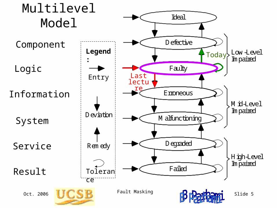
Multilevel Model
Component
Logic
Service
Result
Information
System
Low-Level Impaired
Mid-Level Impaired
High-Level Impaired
Initial Entry
Deviation
Remedy
Legned:
Ideal
Defective
Faulty
Erroneous
Malfunctioning
Degraded
Failed
Legend:
Tolerance
Entry Last lecture
Today
Oct. 2006 Fault Masking Slide 6
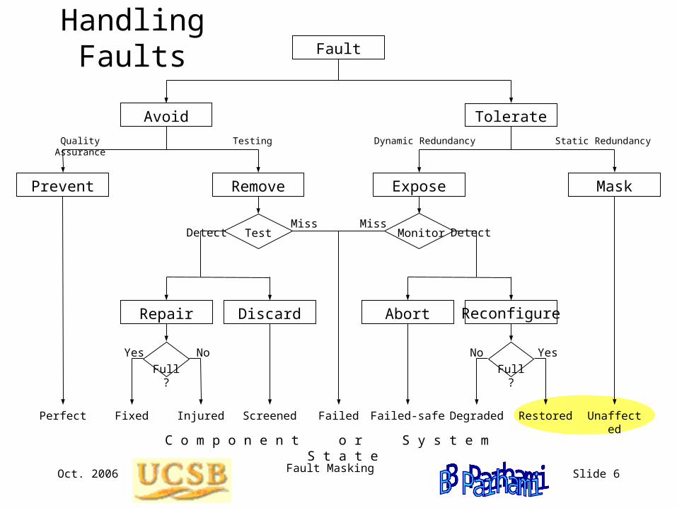
Handling Faults
Repair Discard Abort
Prevent Remove Expose Mask
Avoid Tolerate
Fault
Quality Assurance Testing Dynamic Redundancy Static Redundancy
Full? Full?
MonitorTest
Yes Yes No No
Perfect Fixed Restored UnaffectedInjured Screened Failed-safe DegradedFailed
Detect Miss DetectMiss
C o m p o n e n t o r S y s t e m S t a t e
Reconfigure
Oct. 2006 Fault Masking Slide 7
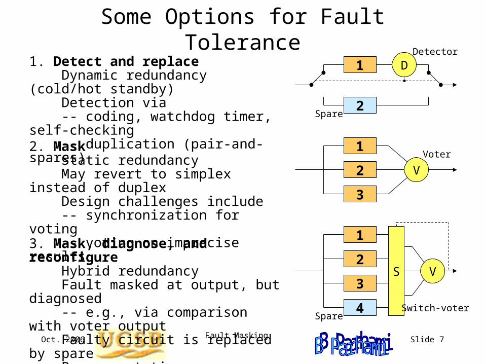
Some Options for Fault Tolerance1. Detect and replace Dynamic redundancy (cold/hot standby) Detection via -- coding, watchdog timer, self-checking -- duplication (pair-and-spares)
2. Mask Static redundancy May revert to simplex instead of duplex Design challenges include -- synchronization for voting -- voting on imprecise results
3. Mask, diagnose, and reconfigure Hybrid redundancy Fault masked at output, but diagnosed -- e.g., via comparison with voter output Faulty circuit is replaced by spare Becomes static upon spare exhaustion
V2
3
1 Voter
D
2
1 Detector
Spare
VS2
3
1
4 Switch-voter Spare
Oct. 2006 Fault Masking Slide 8
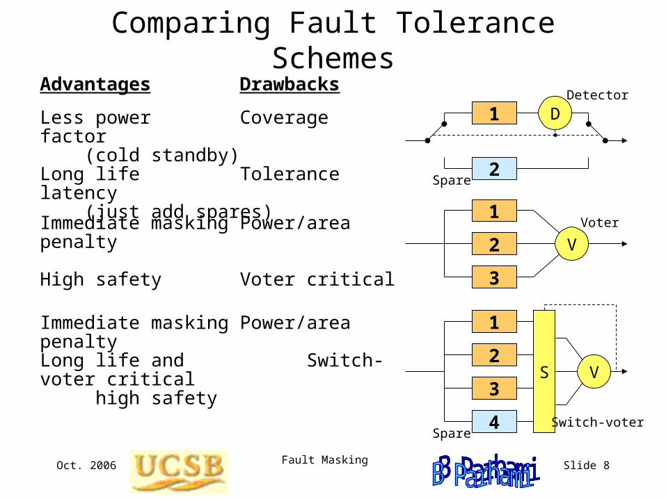
Comparing Fault Tolerance SchemesAdvantages Drawbacks
Less power Coverage factor (cold standby)Long life Tolerance latency (just add spares)
Immediate masking Power/area penalty High safety Voter critical
Immediate masking Power/area penalty
Long life and Switch-voter critical high safety
V2
3
1 Voter
D
2
1 Detector
Spare
VS2
3
1
4 Switch-voter Spare
Oct. 2006 Fault Masking Slide 9
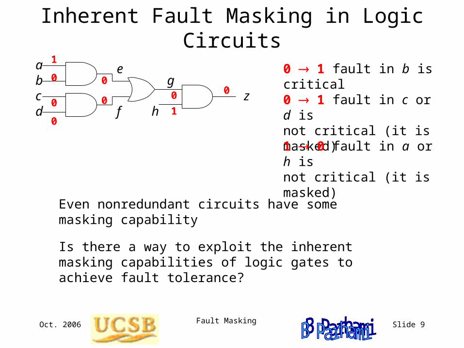
Inherent Fault Masking in Logic Circuits
0 1 fault in b is critical b c
a
d f
g e
h z
1
0 0
0
0
01
0 00 1 fault in c or d is not critical (it is masked)
1 0 fault in a or h is not critical (it is masked)
Even nonredundant circuits have some masking capability
Is there a way to exploit the inherent masking capabilities of logic gates to achieve fault tolerance?
Oct. 2006 Fault Masking Slide 10
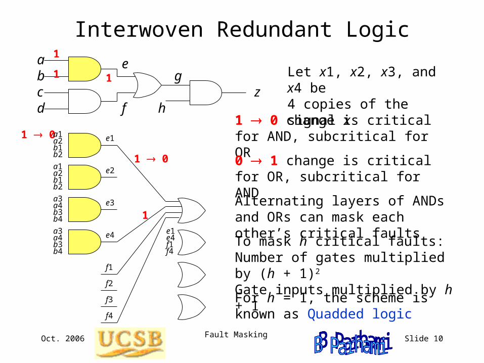
Interwoven Redundant Logic
Let x1, x2, x3, and x4 be 4 copies of the signal x
1 0
b c
a
d f
g e
h z
1 0
a1a2b1b2
a1a2b1b2
a3a4b3b4
a3a4b3b4
e1
e2
e3
e4
f1
f2
f3
f4
e1e4f1f4
1 0 change is critical for AND, subcritical for OR
0 1 change is critical for OR, subcritical for AND
To mask h critical faults: Number of gates multiplied by (h + 1)2 Gate inputs multiplied by h + 1For h = 1, the scheme is known as Quadded logic
Alternating layers of ANDs and ORs can mask each other’s critical faults
1
1 1
1
Oct. 2006 Fault Masking Slide 11
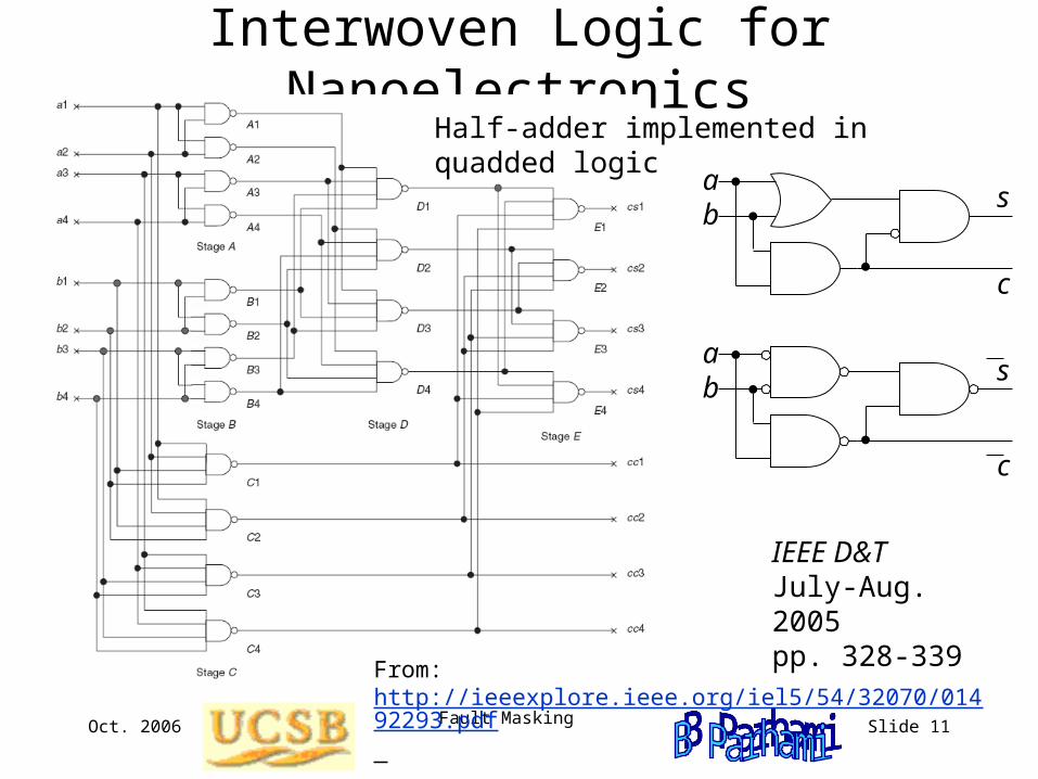
Interwoven Logic for NanoelectronicsHalf-adder implemented in quadded logic
From: http://ieeexplore.ieee.org/iel5/54/32070/01492293.pdf
IEEE D&TJuly-Aug. 2005pp. 328-339
b
c
a s
b a
c
s
Oct. 2006 Fault Masking Slide 12
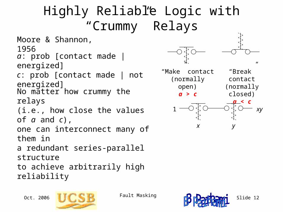
Highly Reliable Logic with “Crummy” Relays
Moore & Shannon, 1956
a: prob [contact made | energized]c: prob [contact made | not energized]
“Make” contact(normally open)
a > c
“Break” contact(normally closed)
a < c
x y
xy1
No matter how crummy the relays(i.e., how close the values of a and c), one can interconnect many of them in a redundant series-parallel structure to achieve arbitrarily high reliability
Oct. 2006 Fault Masking Slide 13
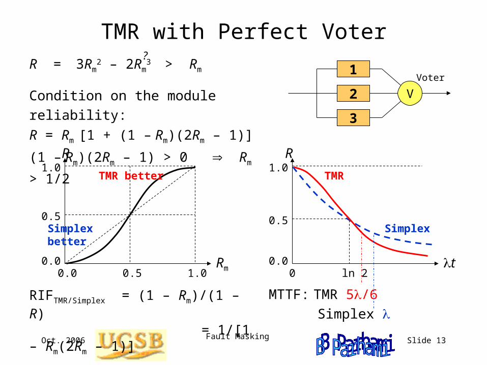
TMR with Perfect Voter
Condition on the module reliability:
R = Rm [1 + (1 – Rm)(2Rm – 1)]
(1 – Rm)(2Rm – 1) > 0 Rm > 1/2
V2
3
1 Voter
R
Rm1.0
0.0
1.0
0.50.0
0.5
TMR better
Simplex better
R
t0
0.5
1.0
ln 20.0
TMR
Simplex
MTTF: TMR 5/6
Simplex
R = 3Rm2 – 2Rm
3 > Rm
?
RIFTMR/Simplex = (1 – Rm)/(1 – R) = 1/[1 – Rm(2Rm – 1)]
Oct. 2006 Fault Masking Slide 14
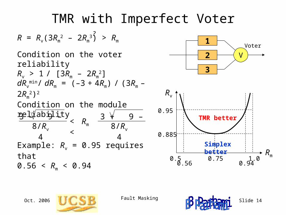
TMR with Imperfect Voter
Condition on the voter reliabilityRv > 1 / [3Rm – 2Rm
2]V2
3
1 Voter
TMR better
Rv
Rm0.5 1.0
0.885
0.95
0.750.56 0.94
Simplex better
Condition on the module reliability
3 – 9 – 8/Rv
4 3 + 9 – 8/Rv
4< Rm <
dRvmin/ dRm = (–3 + 4Rm) / (3Rm – 2Rm
2)2
Example: Rv = 0.95 requires that0.56 < Rm < 0.94
R = Rv(3Rm2 – 2Rm
3) > Rm
?
Oct. 2006 Fault Masking Slide 15
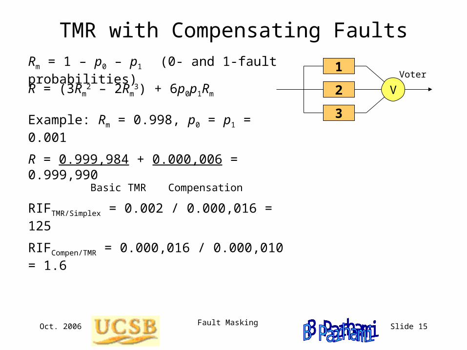
TMR with Compensating Faults
V2
3
1 Voter
Example: Rm = 0.998, p0 = p1 = 0.001
R = 0.999,984 + 0.000,006 = 0.999,990 Basic TMR Compensation
RIFTMR/Simplex = 0.002 / 0.000,016 = 125
RIFCompen/TMR = 0.000,016 / 0.000,010 = 1.6
Rm = 1 – p0 – p1 (0- and 1-fault probabilities)
R = (3Rm2 – 2Rm
3) + 6p0p1Rm
Oct. 2006 Fault Masking Slide 16
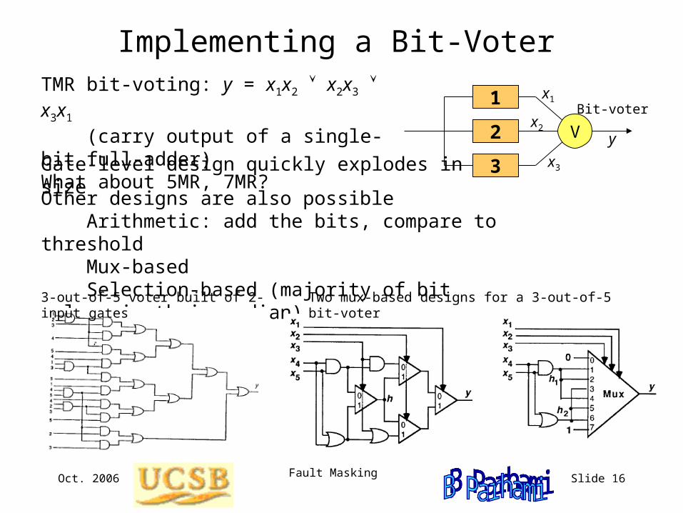
Implementing a Bit-VoterTMR bit-voting: y = x1x2 x2x3 x3x1 (carry output of a single-bit full-adder)What about 5MR, 7MR? V2
3
1 Bit-voter
x1
x2
x3
y
Other designs are also possible Arithmetic: add the bits, compare to threshold Mux-based Selection-based (majority of bit values is their median)
3-out-of-5 voter built of 2-input gates Two mux-based designs for a 3-out-of-5 bit-voter
Gate-level design quickly explodes in size
Oct. 2006 Fault Masking Slide 17
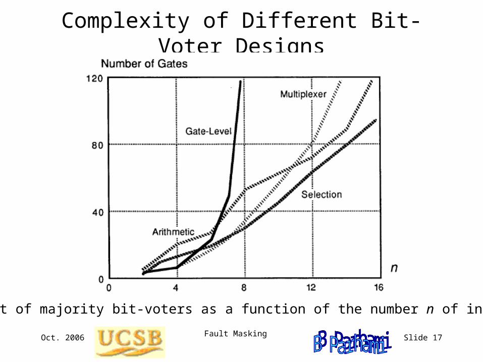
Complexity of Different Bit-Voter Designs
Cost of majority bit-voters as a function of the number n of inputs
Oct. 2006 Fault Masking Slide 18
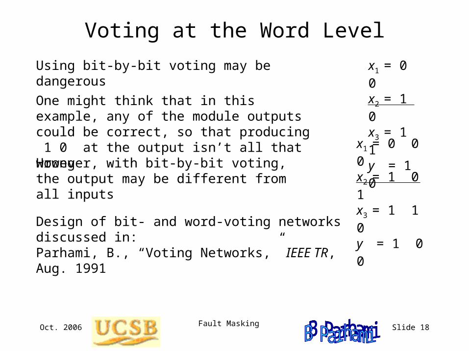
Voting at the Word Level
Using bit-by-bit voting may be dangerous
One might think that in this example, any of the module outputs could be correct, so that producing 1 0 at the output isn’t all that wrong
x1 = 0 0x2 = 1 0x3 = 1 1y = 1 0
However, with bit-by-bit voting, the output may be different from all inputs
x1 = 0 0 0x2 = 1 0 1x3 = 1 1 0y = 1 0 0
Design of bit- and word-voting networks discussed in:Parhami, B., “Voting Networks,” IEEE TR, Aug. 1991
Oct. 2006 Fault Masking Slide 19
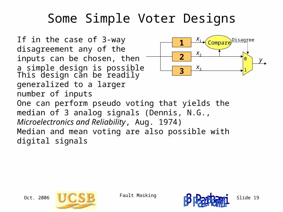
Some Simple Voter Designs
If in the case of 3-way disagreement any of the inputs can be chosen, then a simple design is possible
One can perform pseudo voting that yields the median of 3 analog signals (Dennis, N.G., Microelectronics and Reliability, Aug. 1974)
Median and mean voting are also possible with digital signals
This design can be readily generalized to a larger number of inputs
2
3
1x1
x2
x3
y
Compare
0
1
Disagree
Oct. 2006 Fault Masking Slide 20
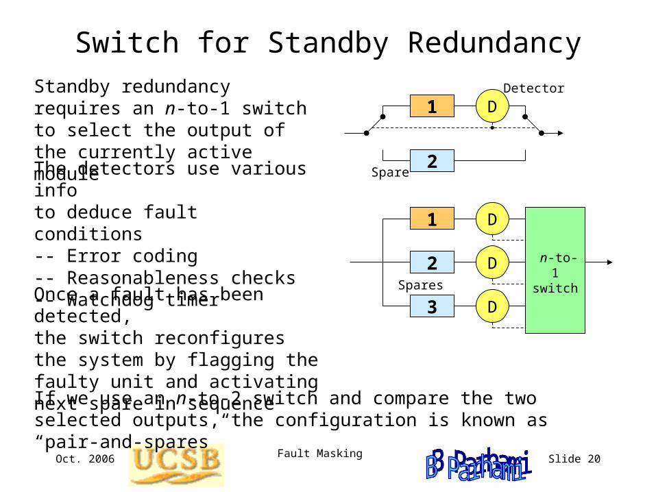
Switch for Standby RedundancyStandby redundancy requires an n-to-1 switch to select the output of the currently active module
The detectors use various info to deduce fault conditions-- Error coding-- Reasonableness checks-- Watchdog timer
D
2
1 Detector
Spare
D
2
1
Spares
D
3 D
n-to-1 switch
Once a fault has been detected, the switch reconfigures the system by flagging the faulty unit and activating next spare in sequence
If we use an n-to-2 switch and compare the two selected outputs, the configuration is known as “pair-and-spares”
Oct. 2006 Fault Masking Slide 21
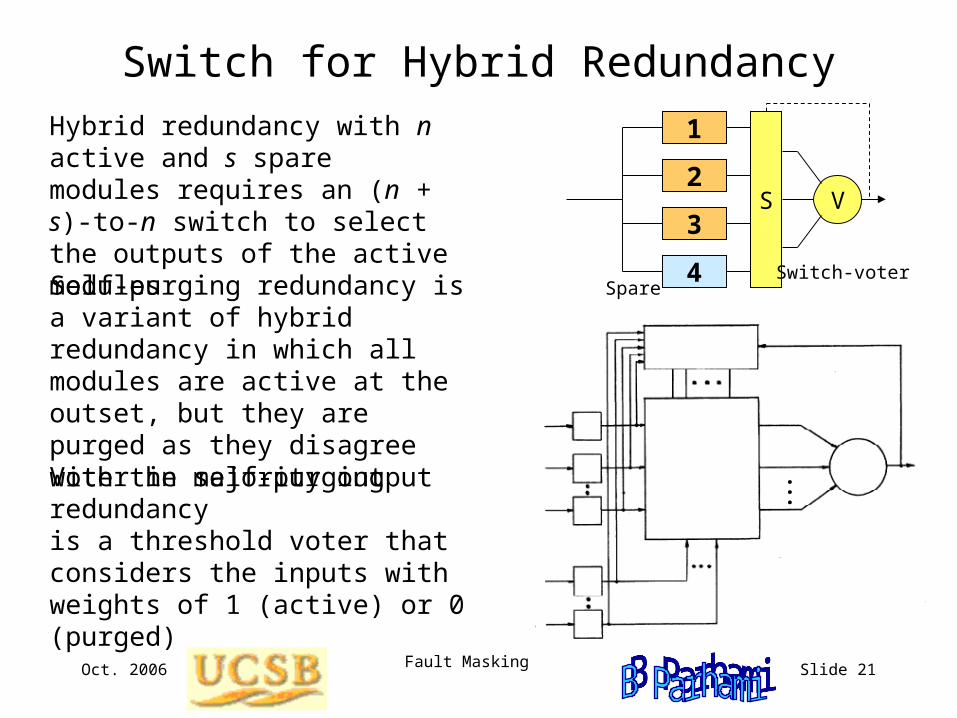
Switch for Hybrid RedundancyHybrid redundancy with n active and s spare modules requires an (n + s)-to-n switch to select the outputs of the active modules
Self-purging redundancy is a variant of hybrid redundancy in which all modules are active at the outset, but they are purged as they disagree with the majority output
VS2
3
1
4 Switch-voter Spare
...Voter in self-purging redundancy is a threshold voter that considers the inputs with weights of 1 (active) or 0 (purged)
Oct. 2006 Fault Masking Slide 22
Applications of nMR and Hybrid Redundancy
The Space Shuttle:
Uses 5-way redundancy in hardware Originally, 3 operational units and 2 spares (one warm, one cold) More recently, 4 operational units and 1 spare
Additionally, uses two independently developed software systems
Japanese Shinkansen “Bullet” Train
Triple-duplex system (6-fold redundancy)
...
Recommended