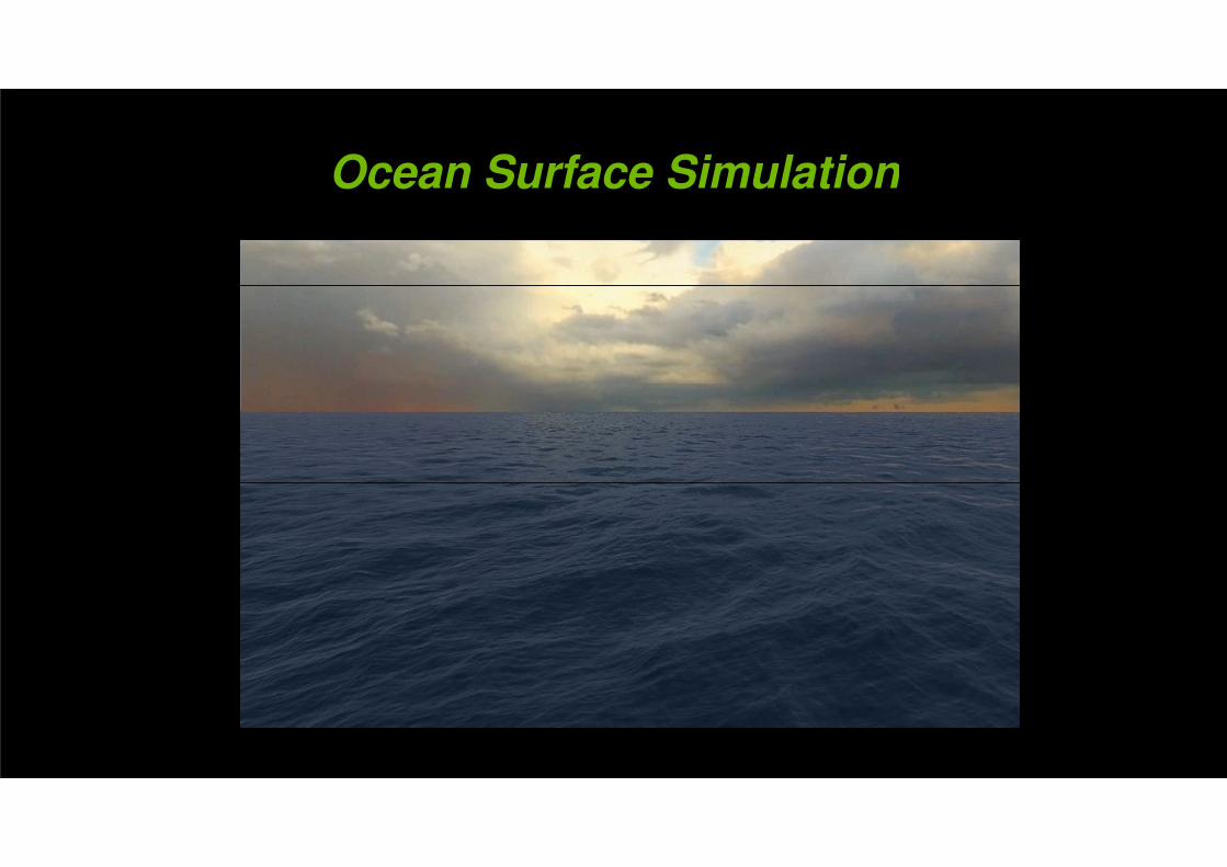
Ocean Surface SimulationOcean Surface Simulation
List of the ContentList of the Content
• Simulation Algorithm• Simulation Algorithm
• Rendering• Rendering
• DirectX Compute Implementation• DirectX Compute Implementation
• Performance• Performance
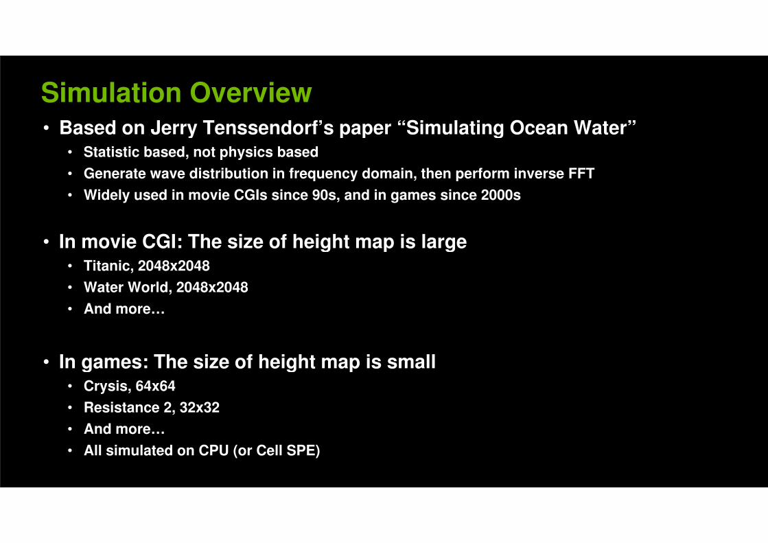
Simulation Overview• Based on Jerry Tenssendorf’s paper “Simulating Ocean Water”• Based on Jerry Tenssendorf’s paper “Simulating Ocean Water”
• Statistic based, not physics based
• Generate wave distribution in frequency domain, then perform inverse FFT • Generate wave distribution in frequency domain, then perform inverse FFT
• Widely used in movie CGIs since 90s, and in games since 2000s
• In movie CGI: The size of height map is large• In movie CGI: The size of height map is large• Titanic, 2048x2048
• Water World, 2048x2048
• And more…• And more…
• In games: The size of height map is small• In games: The size of height map is small• Crysis, 64x64
• Resistance 2, 32x32
• And more…• And more…
• All simulated on CPU (or Cell SPE)
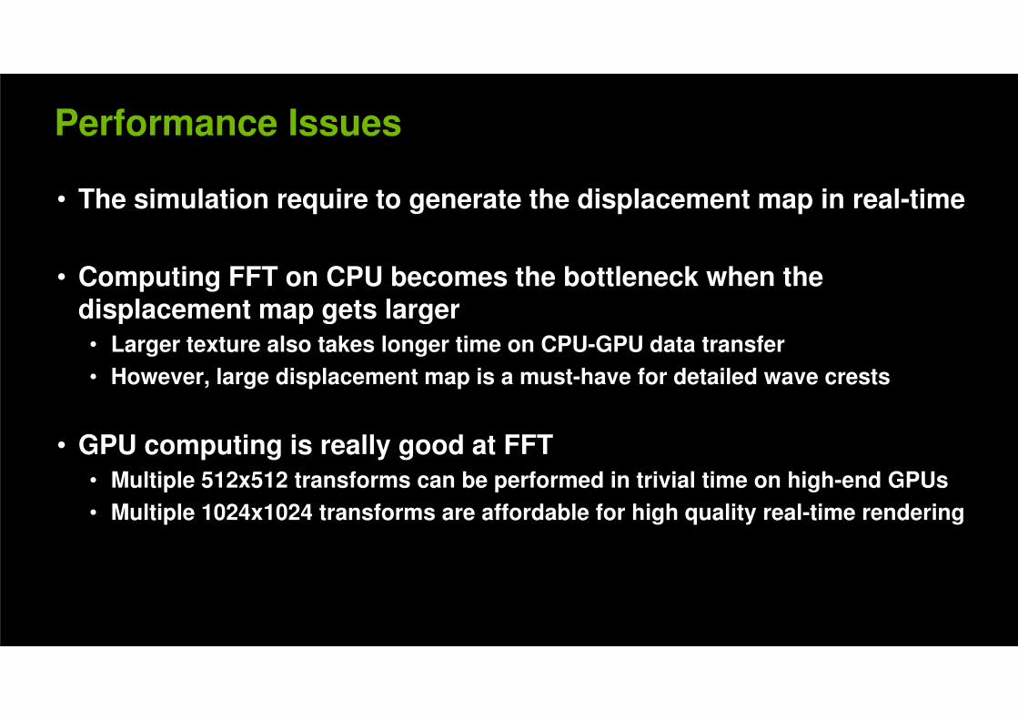
Performance Issues
• The simulation require to generate the displacement map in real-time
• Computing FFT on CPU becomes the bottleneck when the displacement map gets largerdisplacement map gets larger
• Larger texture also takes longer time on CPU-GPU data transfer
• However, large displacement map is a must-have for detailed wave crests
• GPU computing is really good at FFT
• Multiple 512x512 transforms can be performed in trivial time on high-end GPUs• Multiple 512x512 transforms can be performed in trivial time on high-end GPUs
• Multiple 1024x1024 transforms are affordable for high quality real-time rendering
The Algorithm: Wave Composition
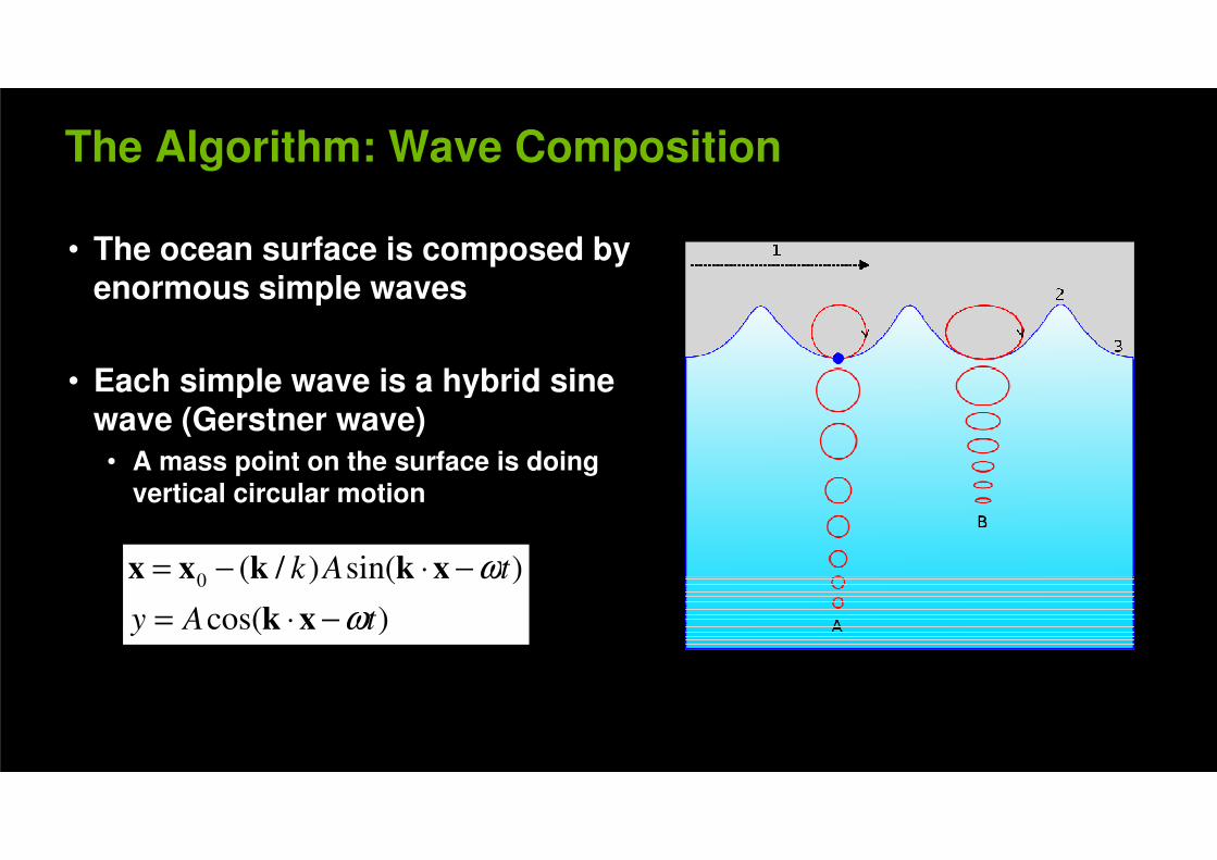
• The ocean surface is composed by enormous simple wavesenormous simple waves
• Each simple wave is a hybrid sine • Each simple wave is a hybrid sine wave (Gerstner wave)
• A mass point on the surface is doing vertical circular motionvertical circular motion
)sin()/(0 tAk ω−⋅−= xkkxx
)cos(
)sin()/(0
tAy
tAk
ω
ω
−⋅=
−⋅−=
xk
xkkxx
The Algorithm: Statistic Model
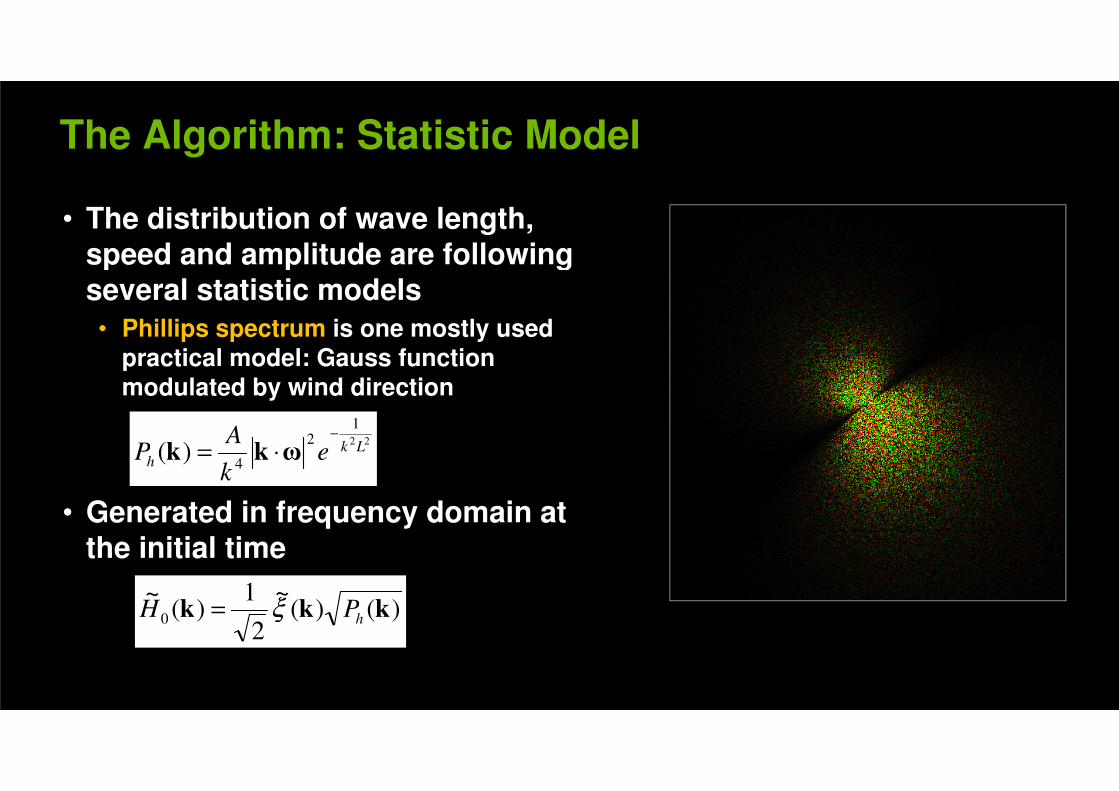
• The distribution of wave length, speed and amplitude are following speed and amplitude are following several statistic models
• Phillips spectrum is one mostly used
practical model: Gauss function practical model: Gauss function modulated by wind direction
22
12
)( LkeA
P−
⋅= ωkk
• Generated in frequency domain at
222
4)( Lk
h ek
AP
−
⋅= ωkk
the initial time
)()(~
2
1)(
~0 kkk hPH ξ= )()(
2)(0 kkk hPH ξ=
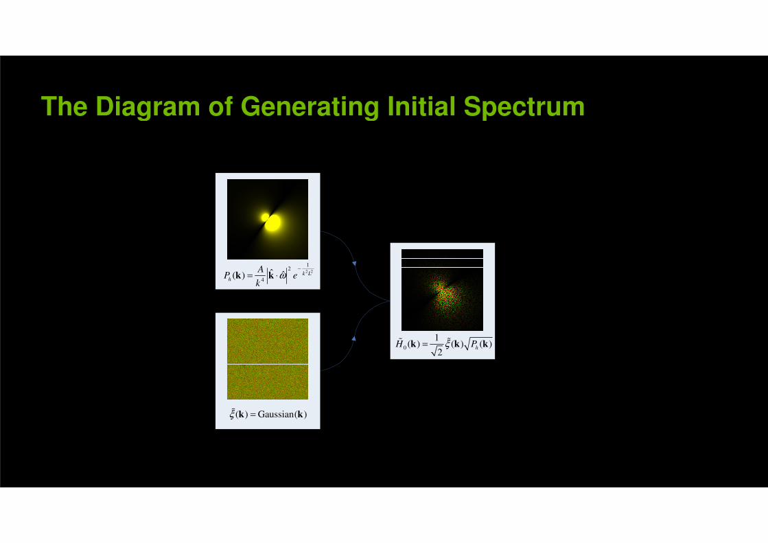
The Diagram of Generating Initial Spectrum The Diagram of Generating Initial Spectrum
2 2
12
4ˆ ˆ( ) k L
h
AP e
kω
−
= ⋅k k
0
1( ) ( ) ( )
2hH Pξ=k k k%%
( ) Gaussian( )ξ =k k%
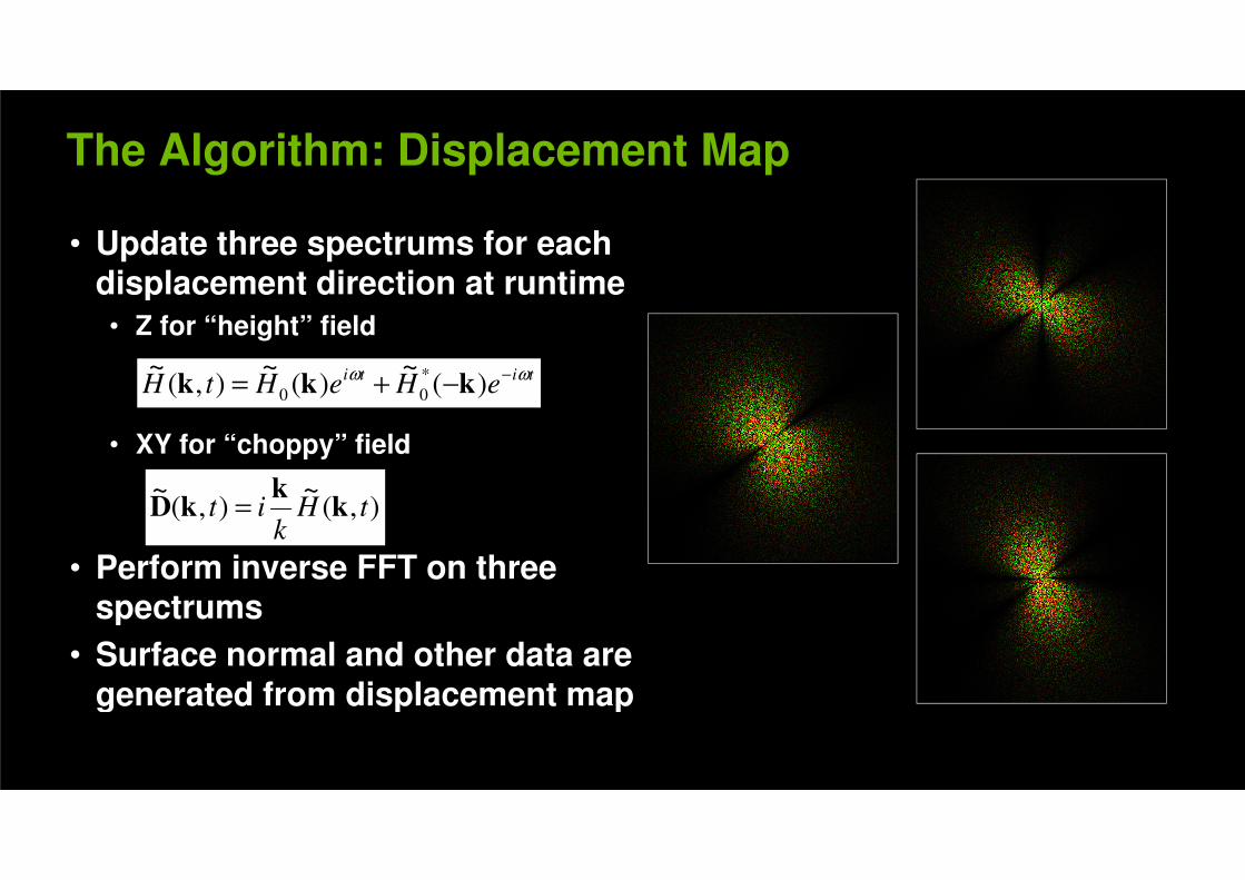
The Algorithm: Displacement Map
• Update three spectrums for each displacement direction at runtimedisplacement direction at runtime
• Z for “height” field
titieHeHtH
ωω −−+= )(~
)(~
),(~ *
00 kkk
• XY for “choppy” field
eHeHtH −+= )()(),( 00 kkk
),(~
),(~
tHit kk
kD =
• Perform inverse FFT on three spectrums
),(~
),(~
tHk
it kk
kD =
spectrums
• Surface normal and other data are
generated from displacement mapgenerated from displacement map
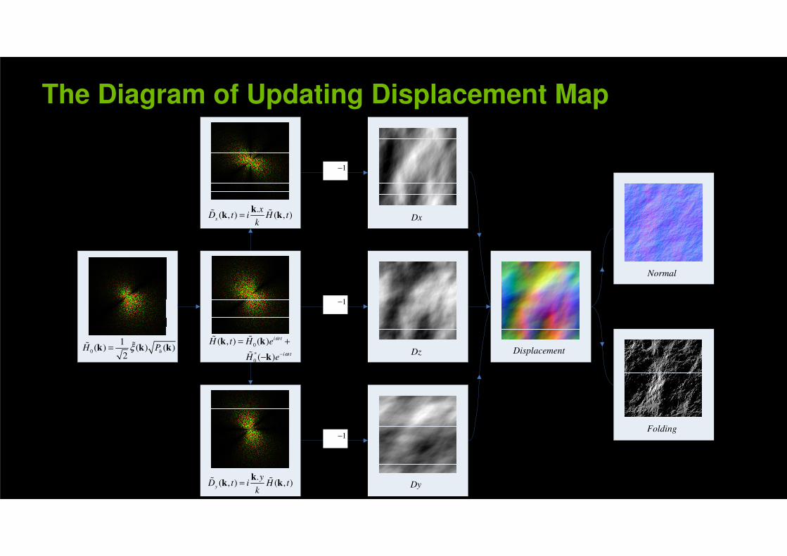
The Diagram of Updating Displacement Map
1−
.( , ) ( , )
x
xD t i H t
k=
kk k% %
Dx
Normal
1−
0
1( ) ( ) ( )
2h
H Pξ=k k k%% 0
*
0
( , ) ( )
( )
i t
i t
H t H e
H e
ω
ω−
= +
−
k k
k
% %
% Dz Displacement
Folding1−
.( , ) ( , )y
yD t i H t
k=
kk k% %
Dy
1−
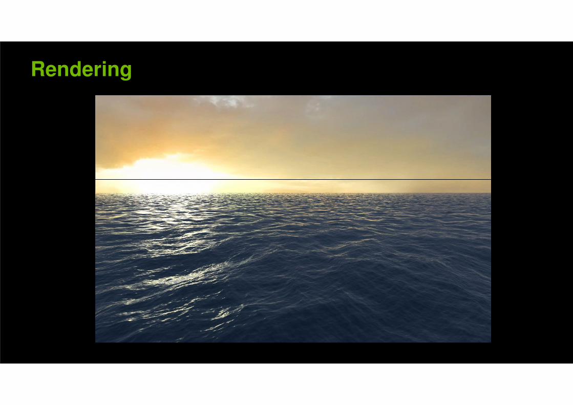
Rendering
Screen Space vs. World Space
• Screen SpacePro
• Minimal mesh wastage
• Can be extended to horizon easily
ConCon• Distracting alias at distance due to undersampling
• Require huge off-screen mesh chunks to cover gaps along the screen edges
• World Space• World SpacePro
• Can be mapped to displacement map straightforwardly
• No undersampling alias
Con• Need more complicated way extending to horizon• Need more complicated way extending to horizon
• Produce many sub-pixel triangles at distance
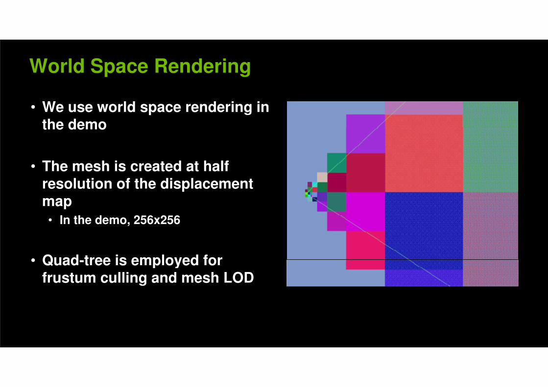
World Space Rendering
• We use world space rendering in the demothe demo
• The mesh is created at half • The mesh is created at half resolution of the displacement map
• In the demo, 256x256• In the demo, 256x256
• Quad-tree is employed for • Quad-tree is employed for frustum culling and mesh LOD
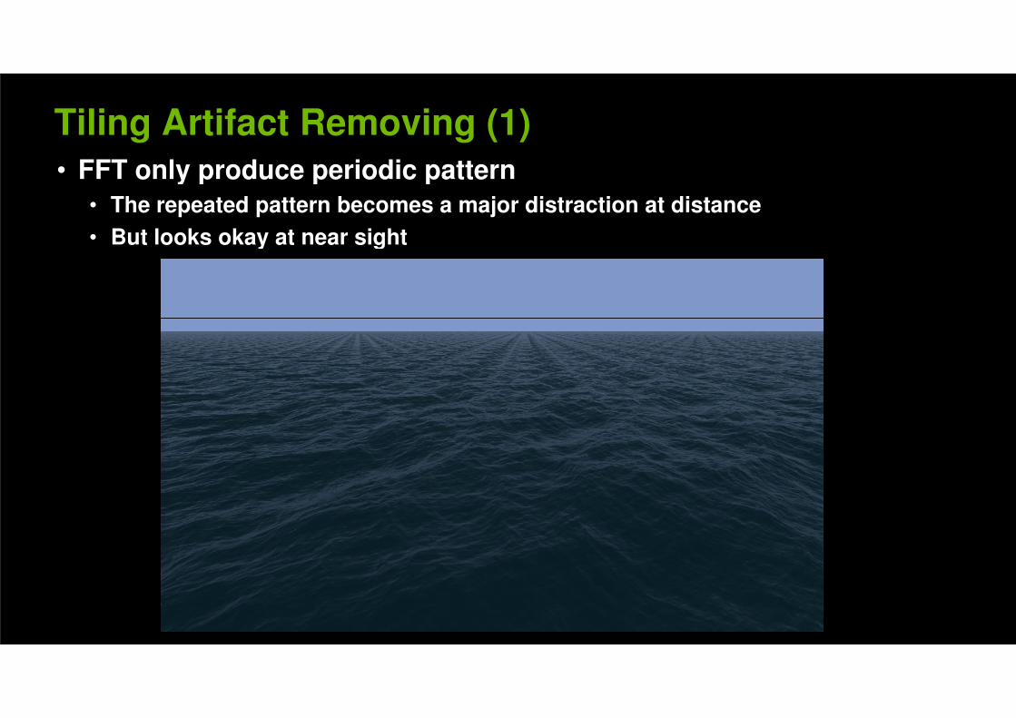
Tiling Artifact Removing (1)
• FFT only produce periodic pattern • FFT only produce periodic pattern
• The repeated pattern becomes a major distraction at distance
• But looks okay at near sight• But looks okay at near sight
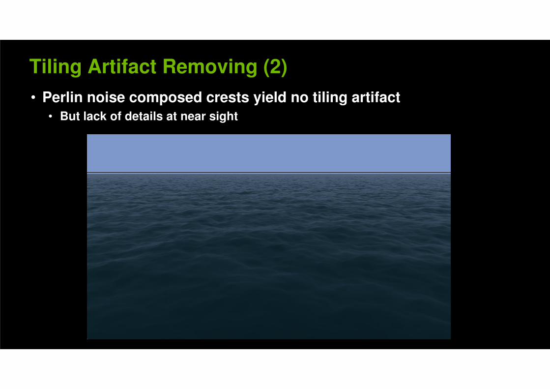
Tiling Artifact Removing (2)
• Perlin noise composed crests yield no tiling artifact
• But lack of details at near sight
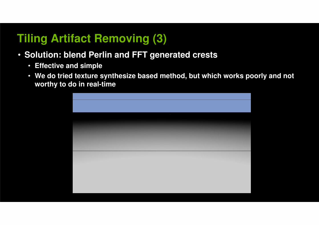
Tiling Artifact Removing (3)
• Solution: blend Perlin and FFT generated crests
• Effective and simple
• We do tried texture synthesize based method, but which works poorly and not • We do tried texture synthesize based method, but which works poorly and not worthy to do in real-time
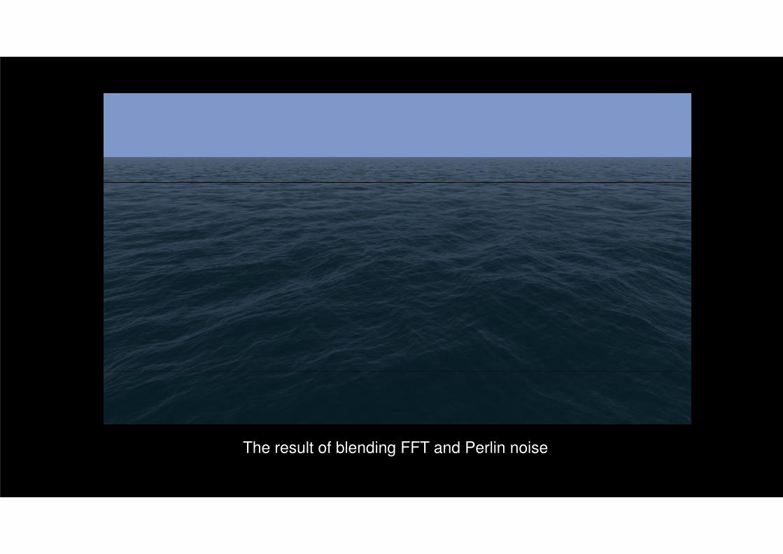
The result of blending FFT and Perlin noise
Ocean Shading (1)
• The demo only rendered for deep ocean water
• Shallow water rendering is much more complicated• Shallow water rendering is much more complicated
• Shading components
• Water body color: using a constant color
• Fresnel term for reflection: read from a pre-computed texture
• Reflected color: using a small cubemap blend with a constant sky color• Reflected color: using a small cubemap blend with a constant sky color
• Vertical streak: computed from a modified specular term
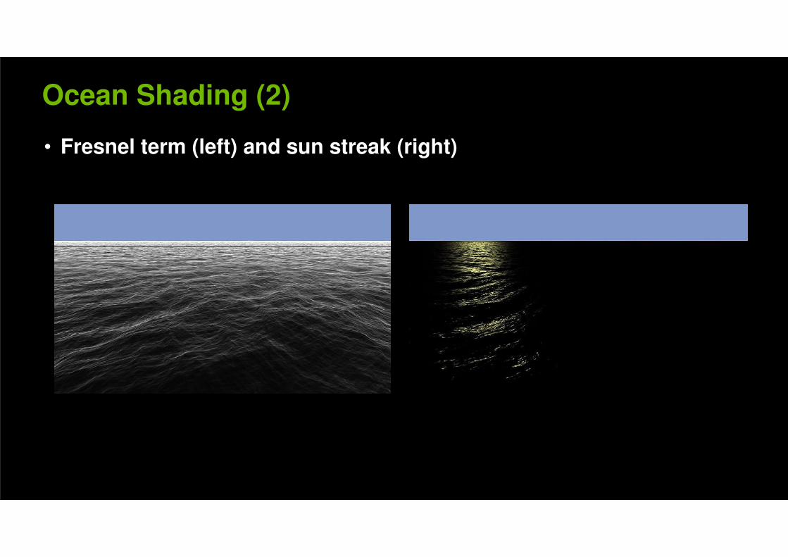
Ocean Shading (2)
• Fresnel term (left) and sun streak (right)
DirectX Compute Implementation
• Use DX Compute to
• Update three spectrums each frame• Update three spectrums each frame
• Perform three 512x512 inverse FFTs each frame
• Use Pixel Shader to• Use Pixel Shader to
• Read the results from FFT and interleave the data into displacement map
• Generate normal map• Generate normal map
Details on DX Compute code
• Inverse FFT
• Currently, only 512x512 transform is implemented in the SDK sample• Currently, only 512x512 transform is implemented in the SDK sample
• Higher than 1024x1024 will produce visible artifact due to FP precision
• Using CS4.0 to run on DX10 level GPU (G8x and later)
• Using complex-to-complex transform for better coalescing performance• Using complex-to-complex transform for better coalescing performance
• UAV usage (Unordered Access View)• UAV usage (Unordered Access View)
• CS4.x only supports 1 UAV per compute shader
• To output to three buffers for the three spectrums, just allocate one big buffer and manage the offsets for each bufferand manage the offsets for each buffer
• A pixel shader is employed to read the transformed data from the UAV and interleave them into a FP32x4 texture
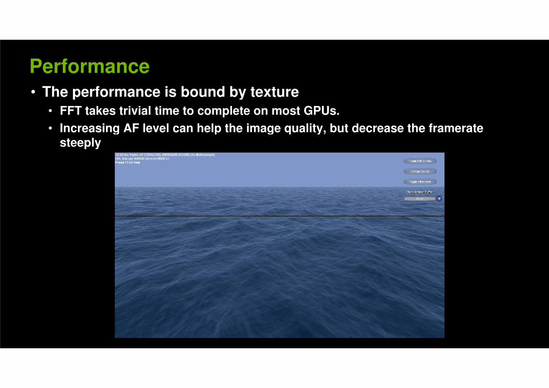
Performance
• The performance is bound by texture• The performance is bound by texture
• FFT takes trivial time to complete on most GPUs.
• Increasing AF level can help the image quality, but decrease the framerate • Increasing AF level can help the image quality, but decrease the framerate steeply
Acknowledgement
• Thanks for Victor Podlozhnyuk for providing FFT code, Simon Green • Thanks for Victor Podlozhnyuk for providing FFT code, Simon Green for various suggestions, Cyril Zeller and Cem Cebenoyan for supporting doing this demo
Recommended