SPACE Research Centre
SPACE Research CentreSchool of Mathematical and Geospatial Sciences
RMIT University, Australiawww.rmit.edu.au/space
Numerical Ray Tracing of GPS Radio
Occultation Paths
R. Norman, K. Zhang, J. Le Marshall, B. Carter,
C. S. Wang, Y. Li, S. Gordon and T. Manning
SPACE Research Centre
4-Apr-12 IROWG-2 2012 / Kefei Zhang 2
Overview
� Background and aim
� Ray tracing
� Refractivity and major features in the Ionosphere
� Refractivity in the Stratosphere and Troposphere
� Ray tracing program
� Simulated GPS to LEO propagation results
� Summary
SPACE Research Centre
4-Apr-12 IROWG-2 2012 / Kefei Zhang 3
ASRP Scheme
• ASRP – Australian Space Research Program
• Recent Australian government initiative
• To support priorities of national space policy
• PNT and earth obs key priorities identified
• Administered by The Australian Ministry of DIISR
• Astronomy, Astrophysics & Cosmology – expressly ruled out
• Competitive ~10% successful rate
• Geospatial / geodesy community is a winner!
– 4 out of 10 funded, 44% of the total funding
• RMIT University
– Platform Technologies for Space, Atmosphere and Climate
• Other projects relevant to IROWG
• Australian National University - GRACE Follow-on Mission
• EOS Space Systems Pty Ltd - Automated Laser Tracking of Space Debris
• UNSW - SAR Formation Flying
SPACE Research Centre
4-Apr-12 IROWG-2 2012 / Kefei Zhang 4
The RMIT led ASRP Project
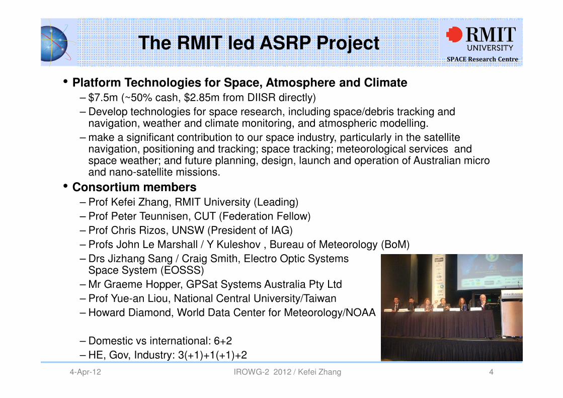
• Platform Technologies for Space, Atmosphere and Climate
– $7.5m (~50% cash, $2.85m from DIISR directly)
– Develop technologies for space research, including space/debris tracking and navigation, weather and climate monitoring, and atmospheric modelling.
– make a significant contribution to our space industry, particularly in the satellite navigation, positioning and tracking; space tracking; meteorological services and space weather; and future planning, design, launch and operation of Australian micro and nano-satellite missions.
• Consortium members
– Prof Kefei Zhang, RMIT University (Leading)
– Prof Peter Teunnisen, CUT (Federation Fellow)
– Prof Chris Rizos, UNSW (President of IAG)
– Profs John Le Marshall / Y Kuleshov , Bureau of Meteorology (BoM)
– Drs Jizhang Sang / Craig Smith, Electro Optic Systems Space System (EOSSS)
– Mr Graeme Hopper, GPSat Systems Australia Pty Ltd
– Prof Yue-an Liou, National Central University/Taiwan
– Howard Diamond, World Data Center for Meteorology/NOAA
– Domestic vs international: 6+2
– HE, Gov, Industry: 3(+1)+1(+1)+2
SPACE Research Centre
4-Apr-12 IROWG-2 2012 / Kefei Zhang 5
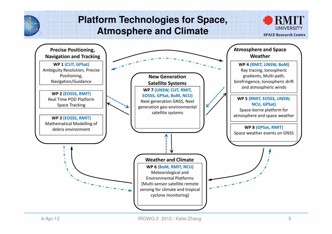
Platform Technologies for Space, Atmosphere and Climate
WP 1 (CUT, GPSat)
Ambiguity Resolution, Precise
Positioning,
Navigation/Guidance
WP 2 (EOSSS, RMIT)
Real Time POD Platform
Space Tracking
WP 3 (EOSSS, RMIT)
Mathematical Modelling of
debris environment
Precise Positioning,
Navigation and Tracking
WP 5 (RMIT, EOSSS, UNSW,
NCU, GPSat)
Space-borne platform for
atmosphere and space weather
WP 4 (RMIT, UNSW, BoM)
Ray tracing, Ionospheric
gradients, Multi-path,
birefringence, Ionospheric drift
and atmospheric winds
Atmosphere and Space
Weather
WP 8 (GPSat, RMIT)
Space weather events on GNSS
WP 7 (UNSW, CUT, RMIT,
EOSSS, GPSat, BoM, NCU)
Next generation GNSS, Next
generation geo-environmental
satellite systems
New Generation
Satellite Systems
WP 6 (BoM, RMIT, NCU)
Meteorological and
Environmental Platforms
(Multi-sensor satellite remote
sensing for climate and tropical
cyclone monitoring)
Weather and Climate
SPACE Research Centre
4-Apr-12 IROWG-2 2012 / Kefei Zhang 6
Aim
� The aim of this study is to use ray tracing technique and the best available ionospheric models to investigate the effects of the ionosphere and atmosphere on GNSS signals. � i.e. refractive bending, elapsed time delay, the received divergent signal strength
� This is important for improving ionosphere and atmosphere retrieval techniques and to help to improve accuracy in GNSS PNT (positioning, navigation and timing).
� The focus of this study is on GNSS RO propagation where we use numerical ray tracing based on geometrical optics to simulate GPS to LEO signal paths.
SPACE Research Centre
4-Apr-12 IROWG-2 2012 / Kefei Zhang 7
Ray tracing Techniques
There are two main forms of ray tracing and they are:
� Numerical Ray tracing
Generally requires a form of Haselgrove equations where these equations are integrated at each step along the ray path
• A new 3-D ray tracing technique developed – to trace a ray tube consisting of the principle ray and a pair of linearly independent ray variations.
• Used to determine the divergent signal strength and also aid homing-in capability
� Analytical ray tracing
Analytical ray tracing as its name suggests uses explicit equations to represent the ionopshere and lower atmosphere as well as the ray parameters.
This technique is much quicker than numerical ray tracing, but in the past has been restricted to much simpler ionospheric models.
• A new 3-D segment method analytical ray tracing technique (3-D SMART) developed.
• It is currently primarily used for HF radar applications
SPACE Research Centre
4-Apr-12 IROWG-2 2012 / Kefei Zhang 8
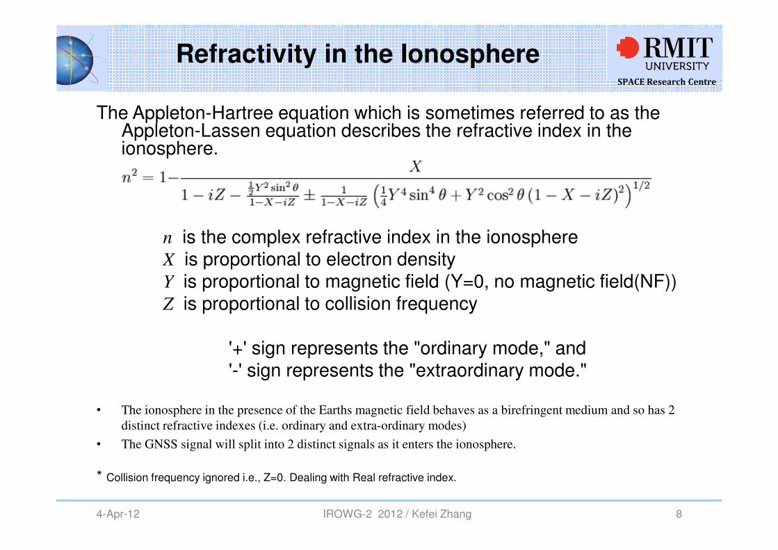
Refractivity in the Ionosphere
The Appleton-Hartree equation which is sometimes referred to as the Appleton-Lassen equation describes the refractive index in the ionosphere.
n is the complex refractive index in the ionosphereX is proportional to electron densityY is proportional to magnetic field (Y=0, no magnetic field(NF))Z is proportional to collision frequency
'+' sign represents the "ordinary mode," and '-' sign represents the "extraordinary mode."
• The ionosphere in the presence of the Earths magnetic field behaves as a birefringent medium and so has 2
distinct refractive indexes (i.e. ordinary and extra-ordinary modes)
• The GNSS signal will split into 2 distinct signals as it enters the ionosphere.
* Collision frequency ignored i.e., Z=0. Dealing with Real refractive index.

SPACE Research Centre
4-Apr-12 IROWG-2 2012 / Kefei Zhang 9
Earth’s Ionosphere
Examples of the vertical layer structure in the ionosphere
The ionosphere is the region from about 60 km to 1000 km in altitude, where the solar radiance produces a partially ionized plasma of mostly H+ and He+ above 1000 km, O+ from 300 to 500 km and molecular ion (NO+, O2+, N2+) below 200 km.
SPACE Research Centre
4-Apr-12 IROWG-2 2012 / Kefei Zhang 10
Major features in the Ionosphere
Some of the major features in the ionosphere are
�Equatorial anomaly
�Mid and high-latitude ionospheric troughs
�Sunrise and sunset terminators
�Seasonal and diurnal variations
�Solar cycle effects and increased solar activity
The refractive gradients in the ionosphere that cause the electromagnetic signal to bend/refract in accordance to Snell’s law, the larger the refractive gradients the more refraction.
It is important to understand the refractive gradients to improve PNT and RO measurements.
SPACE Research Centre
4-Apr-12 IROWG-2 2012 / Kefei Zhang 11
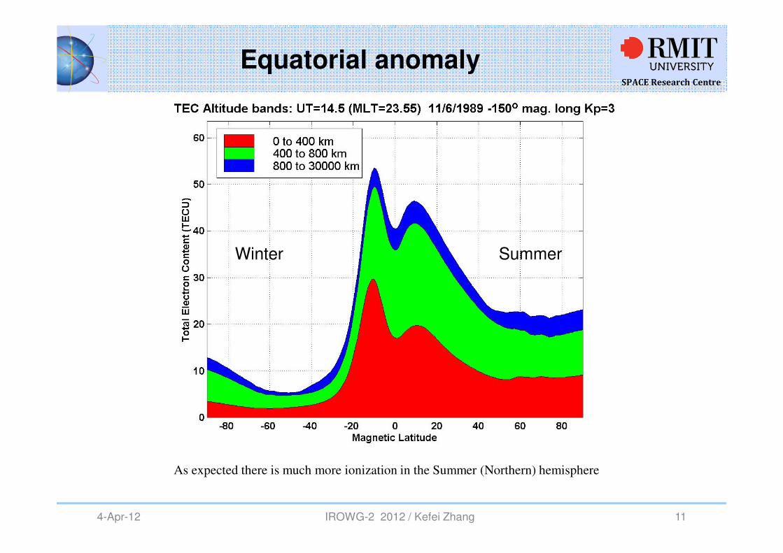
Equatorial anomaly
As expected there is much more ionization in the Summer (Northern) hemisphere
Winter Summer
SPACE Research Centre
4-Apr-12 IROWG-2 2012 / Kefei Zhang 12
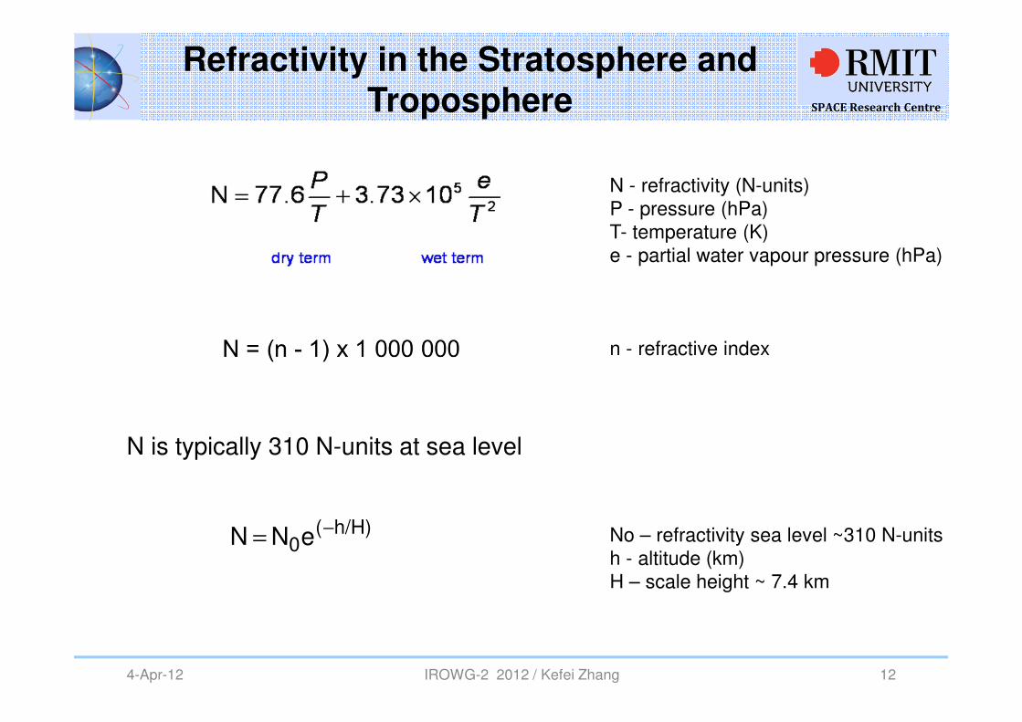
Refractivity in the Stratosphere and
Troposphere
N is typically 310 N-units at sea level
h/H)(0eNN −
=
N - refractivity (N-units)P - pressure (hPa)T- temperature (K)e - partial water vapour pressure (hPa)
n - refractive index
No – refractivity sea level ~310 N-unitsh - altitude (km)H – scale height ~ 7.4 km
SPACE Research Centre
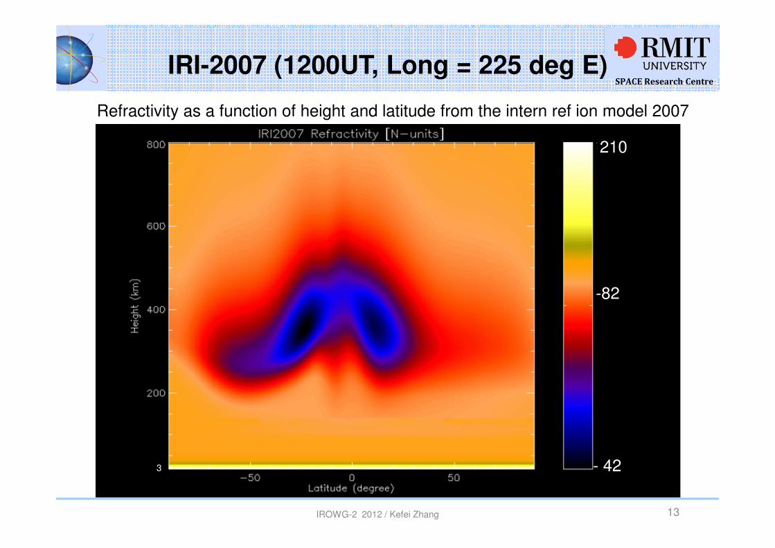
IRI-2007 (1200UT, Long = 225 deg E)
IROWG-2 2012 / Kefei Zhang
210
- 42
-82
3
13
Refractivity as a function of height and latitude from the intern ref ion model 2007
SPACE Research Centre
4-Apr-12 IROWG-2 2012 / Kefei Zhang 14
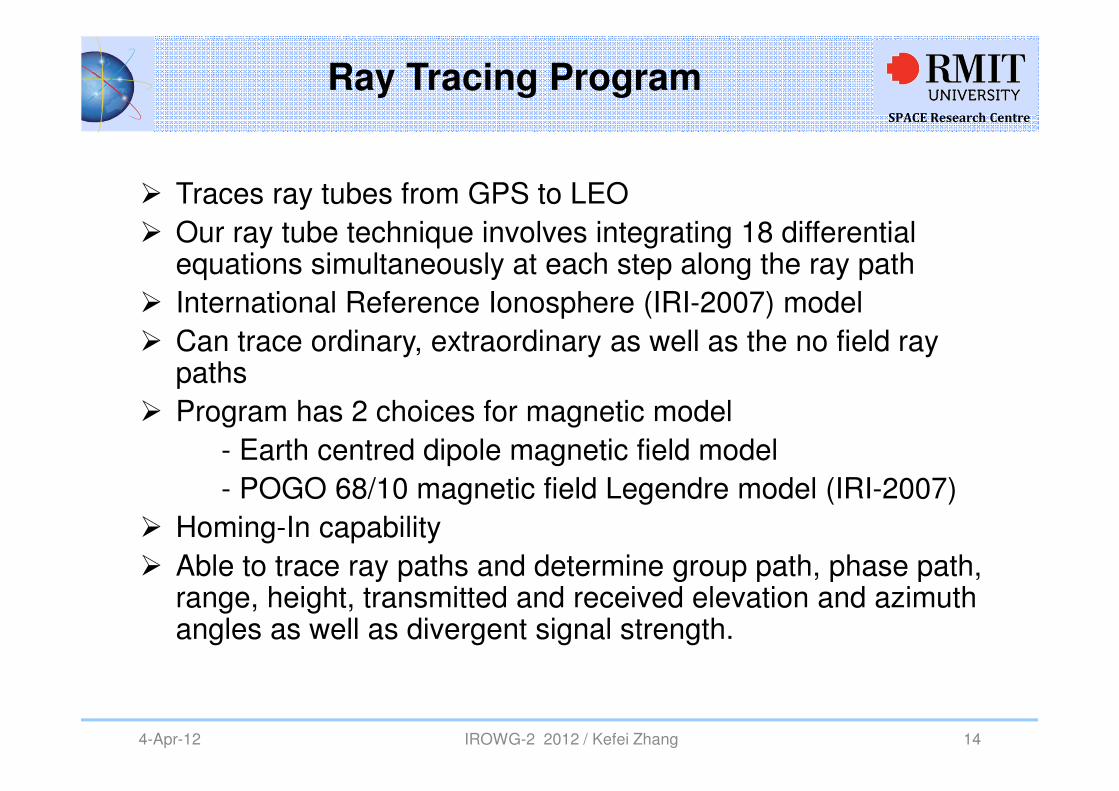
Ray Tracing Program
� Traces ray tubes from GPS to LEO
� Our ray tube technique involves integrating 18 differential equations simultaneously at each step along the ray path
� International Reference Ionosphere (IRI-2007) model
� Can trace ordinary, extraordinary as well as the no field ray paths
� Program has 2 choices for magnetic model
- Earth centred dipole magnetic field model
- POGO 68/10 magnetic field Legendre model (IRI-2007)
� Homing-In capability
� Able to trace ray paths and determine group path, phase path, range, height, transmitted and received elevation and azimuth angles as well as divergent signal strength.
SPACE Research Centre
4-Apr-12 IROWG-2 2012 / Kefei Zhang 15
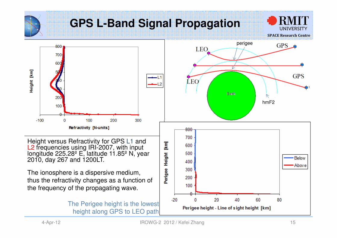
GPS L-Band Signal Propagation
Height versus Refractivity for GPS L1 and L2 frequencies using IRI-2007, with input longitude 225.28º E, latitude 11.85º N, year 2010, day 267 and 1200LT.
The Perigee height is the lowest height along GPS to LEO path
perigeeperigee
hmF2
The ionosphere is a dispersive medium, thus the refractivity changes as a function of the frequency of the propagating wave.
SPACE Research Centre
4-Apr-12 IROWG-2 2012 / Kefei Zhang 16
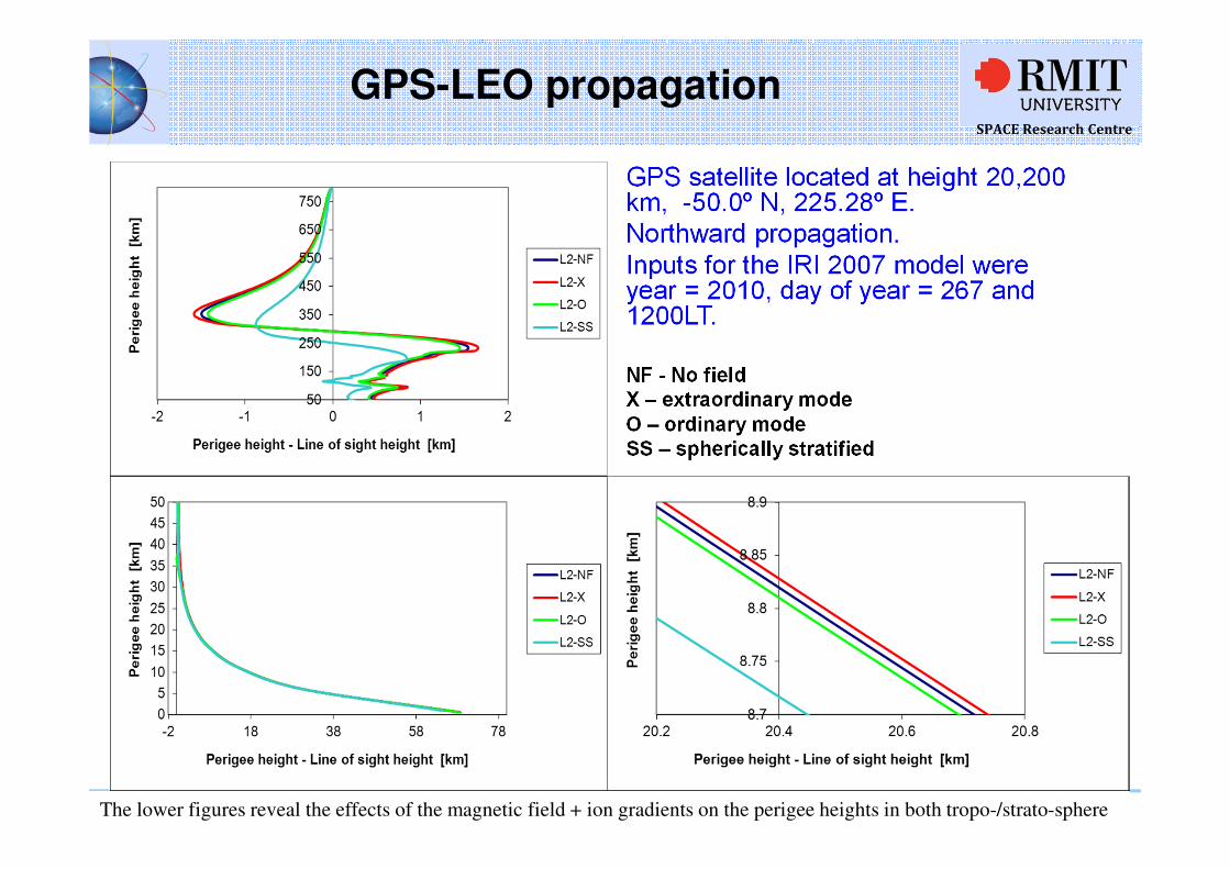
GPS-LEO propagation
GPS satellite located at height 20,200 km, -50.0º N, 225.28º E. Northward propagation. Inputs for the IRI 2007 model were year = 2010, day of year = 267 and 1200LT.
NF - No fieldX – extraordinary modeO – ordinary modeSS – spherically stratified
The lower figures reveal the effects of the magnetic field + ion gradients on the perigee heights in both tropo-/strato-sphere
SPACE Research Centre
4-Apr-12 IROWG-2 2012 / Kefei Zhang 17
Perigee height and Tangent Point
0
100
200
300
400
500
600
700
800
900
25000 26000 27000 28000 29000 30000
Group Path [km]
Pe
rig
ee
he
igh
t [k
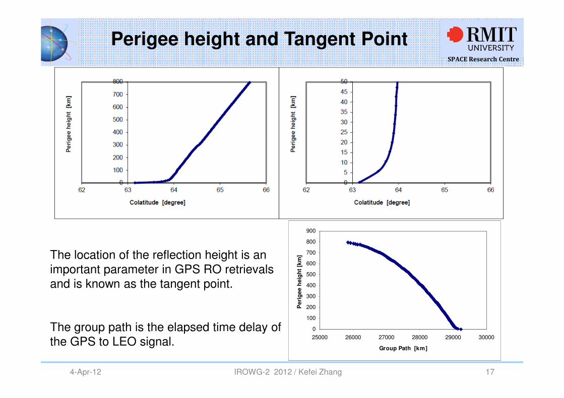
m]The location of the reflection height is an
important parameter in GPS RO retrievals and is known as the tangent point.
The group path is the elapsed time delay of the GPS to LEO signal.
SPACE Research Centre
4-Apr-12 IROWG-2 2012 / Kefei Zhang 18
Signal Strength - divergent power loss
0
200
400
600
800
-186 -184 -182 -180 -178
Divergent Signal Strength [dBm]
Peri
gee h
eig
ht
[km
]
0
10
20
30
40
50
-186 -184 -182 -180 -178
Divergent Signal Strength [dBm]
Peri
gee h
eig
ht
[km
]
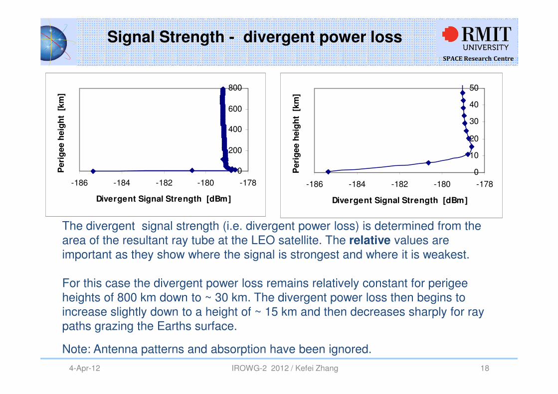
The divergent signal strength (i.e. divergent power loss) is determined from the area of the resultant ray tube at the LEO satellite. The relative values are important as they show where the signal is strongest and where it is weakest.
For this case the divergent power loss remains relatively constant for perigee heights of 800 km down to ~ 30 km. The divergent power loss then begins to increase slightly down to a height of ~ 15 km and then decreases sharply for ray paths grazing the Earths surface.
Note: Antenna patterns and absorption have been ignored.
SPACE Research Centre
4-Apr-12 IROWG-2 2012 / Kefei Zhang 19
Summary
�The aim of this study was to investigate the effects of the ionosphere and atmosphere on GNSS signals. This is important for improving ionosphere and atmosphere retrieval techniques and to help to improve accuracy in GPS positioning and navigation
�In this study we developed a new 3-D numerical ray tracing technique to simulate GPS RO L-band frequency paths.
�Simulated numerical ray paths in the troposphere showed significant bending of more than 60 km above the GPS-LEO line of sight.
�The birefringent nature of the ionosphere produces two distinct signals the extraordinary and the ordinary modes and these signal paths can differ by ~20 metres in the lower atmosphere.
SPACE Research Centre
SPACE Research CentreSchool of Mathematical and Geospatial Sciences
RMIT University, Australiawww.rmit.edu.au/space
Thank you
IROWG Denver 2012 Kefei Zhang (RMIT)20
Professor Kefei Zhang
Satellite Positioning for Atmosphere, Climate and Environment (SPACE) Research CentreSchool of Mathematical and GeoSpatial Sciences
RMIT University
Tel: +61-3-99253272, [email protected], http://www.rmit.edu.au/SPACE
Recommended