International Journal of Energy and Power Engineering 2016; 5(2): 83-89 http://www.sciencepublishinggroup.com/j/ijepe doi: 10.11648/j.ijepe.20160502.18 ISSN: 2326-957X (Print); ISSN: 2326-960X (Online)
Numerical Analysis of Thermosyphon Solar Water Heaters
Samuel Sami, Edwin Marin, Jorge Rivera
Research Center for Renewable Energy, Catholic University of Cuenca, Cuenca, Ecuador
Email address: [email protected] (S. Sami)
To cite this article: Samuel Sami, Edwin Marin, Jorge Rivera. Numerical Analysis of Thermosyphon Solar Water Heaters. International Journal of Energy and
Power Engineering. Vol. 5, No. 2, 2016, pp. 83-89. doi: 10.11648/j.ijepe.20160502.18
Received: January 26, 2016; Accepted: February 3, 2016; Published: May 11, 2016
Abstract: This paper presents the modeling and simulation as well as validation of a natural circulation closed
thermosyphon glass tube solar collector water heater. Energy conservation equations for the heat transfer fluid flow and the
storage tank were written in finite-difference form, integrated and solved to yield the characteristics of the thermosyphon
system at different solar insolations and water mass flow rate conditions as well as water temperatures. Comparison between
experimental data and numerical prediction of the proposed showed that the model predicted fairly the evacuation of storage
tank temperature at various initial temperature of the water at the storage tank.
Keywords: Thermal Solar Collector, Thermosyphon, Water Heater, Modeling, Analysis Validation
1. Introduction
Water heating typically represents a significant percentage
of energy consumption in domestic, industrial applications.
Carbon baseline fuels water heating produce emissions of
greenhouse gases and other pollutants. Due to high cost
primary energy resources and their associated with serious
environmental issues, solar energy is an alternative viable
source of energy for water heating. Solar water heating can
be characterized as active or passive [1-5]. An active system
is based on an electric pump to circulate the working fluid
through the solar collector. In passive solar water heating,
heat-transfer fluid uses thermosyphoning phenomenon to
circulate the water by the buoyancy forces and is replaced by
colder water from the bottom of the tank [5]. This continuous
circulation continues until heats up water in the storage tank
(Figure 1).
Abgo reported on the performance profile of a
thermosyphon solar water heater [6]. The performance
evaluation was based on the mathematical models that
describe the test system and some measured experimental
data. The effect of some of the design and operating
parameters that have been shown to affect the system’s
performance was investigated. Numerical simulation of
steady state natural convection heat transfer in a 3-
dimensional single-ended tube subjected to a nanofluid has
been presented by Shahi et al. [7]. It was a simplified model
for single-ended evacuated solar tube of water glass
evacuated solar water tube heater. It was assumed in the
model that the water sealed tube is adiabatic and also the tube
opening is subject to copper-water nanofluid. Governing
equations were based upon cylindrical coordinate system.
Another numerical analysis of a modified evacuated tubes
solar collector was presented by Sato, et al. [8]. This paper
proposed a study of solar water heating with evacuated tubes,
their operation, characteristics and operating parameters.
Furthermore, another analytical study was reported by
Hammadi [9] on the study of solar water heating system with
natural circulation in Basrah. The results show that the
performance of the solar water heater depends on parameters
such as tilt angle and orientation of the collector, wind
velocity, area of the collector, latitude, and solar time.
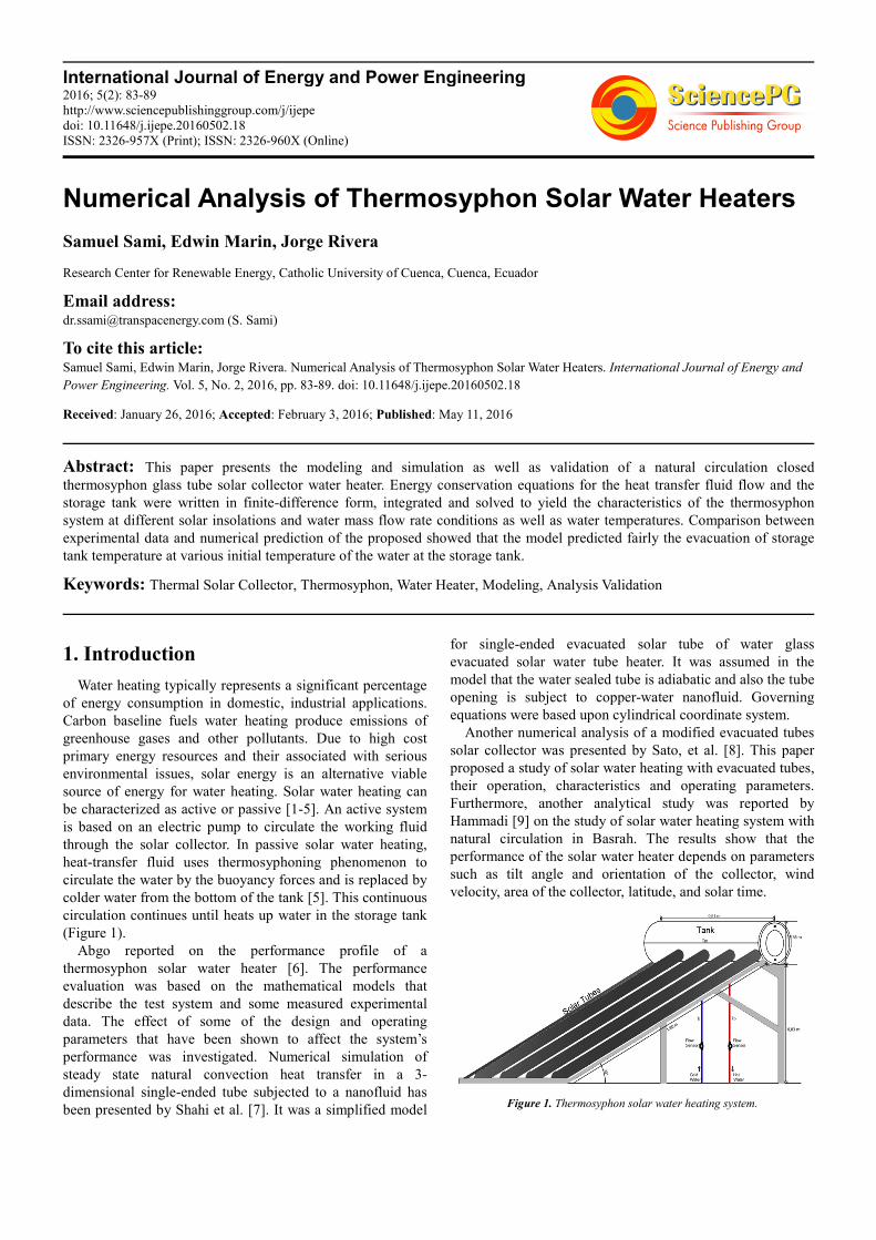
Figure 1. Thermosyphon solar water heating system.
84 Samuel Sami et al.: Numerical Analysis of Thermosyphon Solar Water Heaters
2. Mathematical Model
A schematic of the system under study is depicted in
Figure 1. The system consists of a thermal solar panel, with
solar glass tubes as water tube heater and control valves.
Specifications of the solar glass tube collector are given in
Table.1. As in passive solar water heating system, the water
as heat-transfer fluid uses thermosyphoning phenomenon to
circulate between the solar tubes and tank. With the
buoyancy forces colder water is replaced from the bottom of
the tank. This continuous circulation continues until heats up
water in the storage tank (Figure 1). The storage was filled
with 150 liters of water and the working fluid tubes were
filled with working fluid. The working fluid flows inside the
tubes in the collectors and by thermosyphoning back to the
solar water storage tank. In the solar collector the solar
radiation is absorbed by the working fluid. Due to the
absorption of solar radiation, working fluid temperature
increases. Thus, because of the difference of working fluid
densities, the heated working fluid moves upward to the
storage tank. The heat from the working fluid is transferred to
the cold water and increases its temperature in storage tank.
The following parameters were recorded at 1 minute intervals
for the purpose of validation of the proposed model; cold
water temperature working fluid temperature, solar collector
temperature, storage tank temperature, solar insolation
(W/m2), ambient temperature, wind velocity (m/sec.), hot
water temperature and relative humidity (%).
The conservation equations and heat transfer equations
were written for each water solar glass tube collector, storage
tank and heat transfer fluid as follows;
Energy conservation and heat transfer equations:
The mass flow rate circulating through the solar glass tube
collector can be calculated using the following formula [9];
128 ������
= � � �´ ��� − ��� ��� ��� �� + � (1)
Equation (1) can be rewritten as follows;
! = "# $ %´ �&'( &)��*� +,- ./ 01 ����
2�3 �� (2)
and;
�� − �� = 4∝6�(7 6��&8(&9�:;<
(3)
Where Tm is;
�� = &'0&)� (4)
The heat transfer coefficient of wind is given by [9, 10];
ℎ = 2.8 + 3 @A�B (5)
In addition, the following parameters; density, specific
heat, coefficient of water expansion, as well as volume of
storage tank are defined as follows respectively;
= 1001 − 0.08832� − 0.003427�� (6)
FG = 4226 − 3.244� + 0.00575�� − 0.0003656� (7)
�´ = �0.3 + 0.116� − 0.0004���10(J (8)
K = L 2�.M2MM0�.�2N�& − 0.12O 10(P (9)
Meanwhile, the energy equation for the thermosyphon
solar water heater during daily solar radiation can be written
as follows [6];
Q &�R + S��� − ��� + TU�V�FG ��� − ��� = W��XY�; Z´ [; (10)
The rate of water evacuated from the storage tank is given
by;
&�R = \'�]^�� _´ 6�( `a�&8( &'�(b��R�c< �&8( &'�d
e (11)
Where τα_ is effective transmittance-absorptance and F1
represents collector efficiency factor, and U is collector
overall heat loss coefficient.
W, and Tm are the total heat capacity of the system, and
the mean system temperature respectively. B is a constant
which can be taken as 1 if water is drawn from the middle of
the tank and 2 if it drawn from the top of the tank [6].
The solar collector energy conversion efficiency can be
calculated as follows;
Ƞc= Qu/Ac Io (12)
Where Qu is energy absorbed by the collector.
The energy absorbed by the collector can be obtained as
follows [6];
Qu = Ac F1[ Io (τα) – Ul ( Tm-Ta)] (13)
Where,
F1: is the collector efficiency factor
Ul: is the collector overall heat loss coefficient (W/m2K)
Solving the aforementioned mentioned equations yield the
water mass flow rate evacuated from the storage tank, energy
absorbed by solar collector, energy conversion efficiency as
well the storage tank temperature during the water evacuation
from the tank.
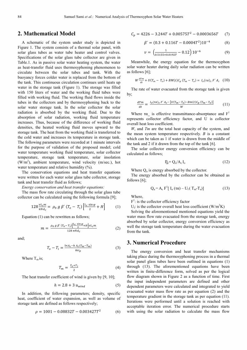
3. Numerical Procedure
The energy conversion and heat transfer mechanisms
taking place during the thermosyphoning process in a thermal
solar panel glass tubes have been outlined in equations (1)
through (13). The aforementioned equations have been
written in finite-difference form, solved as per the logical
flow diagram shown in Figure 2 as a function of time. First
the input independent parameters are defined and other
dependent parameters were calculated and integrated to yield
evacuated water mass flow rate as per equation (2) and the
temperature gradient in the storage tank as per equation (11).
Iterations were performed until a solution is reached with
acceptable iteration error. The numerical procedure starts
with using the solar radiation to calculate the mass flow
International Journal of Energy and Power Engineering 2016; 5(2): 83-89 85
water circulating in the solar panel due buoyancy forces. This
follows by predicting the water temperature profile as a
function of time.
Table 1. Specifications of the water glass solar tubes collector.
SUNSHORE VACUUM TUBES SPECIFICATION
Model 58*1800
Material Borosilicate glass
Outer tube dia Ȼ 58 mm
Inner tube dia Ȼ 47 mm
Tubes length 1800 mm
Tubes number 10
Thickness 1.6 mm
Vacuum inner pressure ≤ 5.0 x 10⁻³ Pa
Absorptivity ≥ 0.92 (AM 1.5)
Emissivity ≤ 0.08 (80°C ± 5°C)
Absorptivity coating Al/Copper/Stainless or Al/N/AL
Thermal expansion 3.3
Stagnation temperature ≥ 270°C
Heat loss 22 W/(m3, K)
Maximum strength
30mm iron ball dropped directly against the
tubes from 450mm high attitude, the tube
without any damages
Anti-freezing - 30°C
Resist Hailstone 25 mm diameter hailstone
Life time 15 years
Figure 2. Logical flow diagram.
4. Results and Discussion
The thermosyphon solar water heater shown in Figure. 1,
has specifications outlined in Table. 1. The storage tank
capacity of 150 liters was connected to plastic pipes
connections for the circulation of the water from and to the
collector. In this section, we first present numerical
simulation results of the solar water heater system presented
in reference [6] under various conditions and secondly
validate our proposed model with experimental data.
The aforementioned system of equations (1) through (13)
in finite-difference formulation has been numerically solved
and samples of the predicted results are plotted in Figures 3
through 15 under different inlet conditions such as insolation,
heat transfer fluid flow rates and heat transfer fluid
temperatures as well as solar panel inclination angles. In
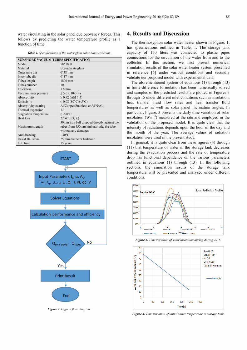
particular, Figure. 3 presents the daily time variation of solar
insolation (W/m2) measured at the site and employed in the
validation of the proposed model. It is quite clear that the
intensity of radiations depends upon the hour of the day and
the month of the year. The average values of radiation
insolation were used in the present study.
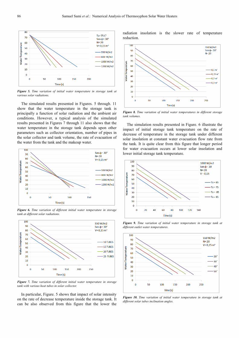
In general, it is quite clear from these figures (4) through
(11) that temperature of water in the storage tank decreases
during the evacuation process and the rate of temperature
drop has functional dependence on the various parameters
outlined in equations (1) through (13). In the following
sections, the simulation results of the storage tank
temperature will be presented and analyzed under different
conditions.
Figure 3. Time variation of solar insolation during during 2015.
Figure 4. Time variation of initial water temperature in storage tank.
86 Samuel Sami et al.: Numerical Analysis of Thermosyphon Solar Water Heaters
Figure 5. Time variation of initial water temperature in storage tank at
various solar radiations.
The simulated results presented in Figures. 5 through. 11
show that the water temperature in the storage tank is
principally a function of solar radiation and the ambient air
conditions. However, a typical analysis of the simulated
results presented in Figures 7 through 11 also shows that the
water temperature in the storage tank depends upon other
parameters such as collector orientation, number of pipes in
the solar collector and tank volume, the rate of evacuation of
the water from the tank and the makeup water.
Figure 6. Time variation of different initial water temperature in storage
tank at different solar radiations.
Figure 7. Time variation of different initial water temperature in storage
tank with various heat tubes in solar collector.
In particular, Figure. 5 shows that impact of solar intensity
on the rate of decrease temperature inside the storage tank. It
can be also observed from this figure that the lower the
radiation insolation is the slower rate of temperature
reduction.
Figure 8. Time variation of initial water temperatures in different storage
tank volumes.
The simulation results presented in Figure. 6 illustrate the
impact of initial storage tank temperature on the rate of
decrease of temperature in the storage tank under different
solar insolation at constant water evacuation flow rate from
the tank. It is quite clear from this figure that longer period
for water evacuation occurs at lower solar insolation and
lower initial storage tank temperature.
Figure 9. Time variation of initial water temperature in storage tank at
different outlet water temperatures.
Figure 10. Time variation of initial water temperature in storage tank at
different solar tubes inclination angles.
International Journal of Energy and Power Engineering 2016; 5(2): 83-89 87
However, Figure. 7 showed that increasing the number of
solar tubes will prolong the water evacuation time of the
storage water tank at constant solar insolation. It is also
evident from the results presented in this figure that the
higher the number of solar tubes the higher the water storage
tank temperature.
Figure 8 has been constructed to examine the impact of the
storage tank volume on the time variation of initial water
temperature and the water evacuation time from the storage
tank. It is obvious that the bigger the storage tank volume the
longer period the evacuation takes.
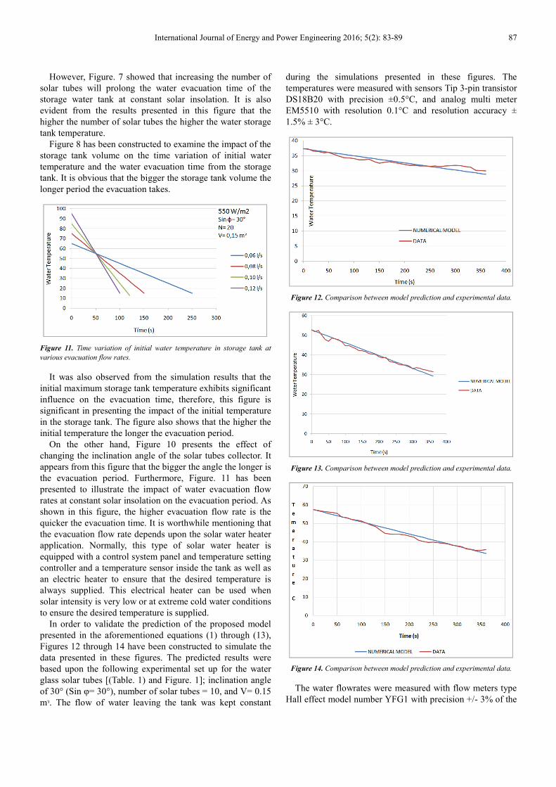
Figure 11. Time variation of initial water temperature in storage tank at
various evacuation flow rates.
It was also observed from the simulation results that the
initial maximum storage tank temperature exhibits significant
influence on the evacuation time, therefore, this figure is
significant in presenting the impact of the initial temperature
in the storage tank. The figure also shows that the higher the
initial temperature the longer the evacuation period.
On the other hand, Figure 10 presents the effect of
changing the inclination angle of the solar tubes collector. It
appears from this figure that the bigger the angle the longer is
the evacuation period. Furthermore, Figure. 11 has been
presented to illustrate the impact of water evacuation flow
rates at constant solar insolation on the evacuation period. As
shown in this figure, the higher evacuation flow rate is the
quicker the evacuation time. It is worthwhile mentioning that
the evacuation flow rate depends upon the solar water heater
application. Normally, this type of solar water heater is
equipped with a control system panel and temperature setting
controller and a temperature sensor inside the tank as well as
an electric heater to ensure that the desired temperature is
always supplied. This electrical heater can be used when
solar intensity is very low or at extreme cold water conditions
to ensure the desired temperature is supplied.
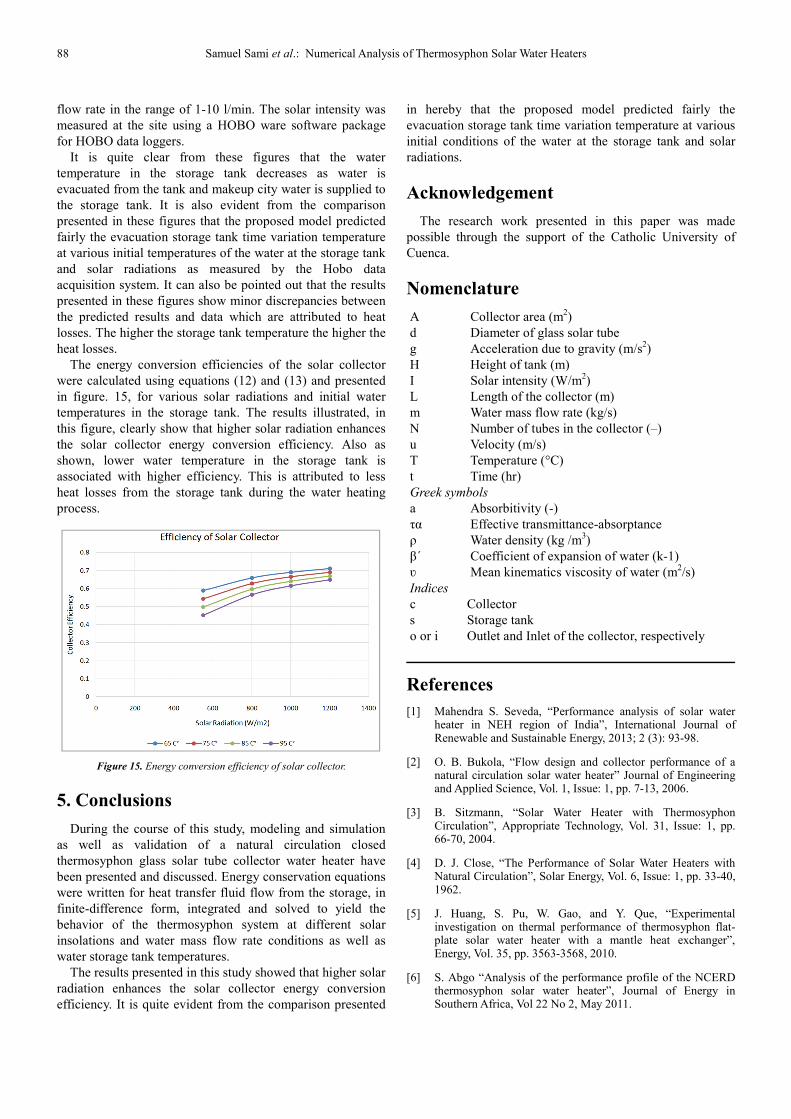
In order to validate the prediction of the proposed model
presented in the aforementioned equations (1) through (13),
Figures 12 through 14 have been constructed to simulate the
data presented in these figures. The predicted results were
based upon the following experimental set up for the water
glass solar tubes [(Table. 1) and Figure. 1]; inclination angle
of 30° (Sin φ= 30°), number of solar tubes = 10, and V= 0.15
mᵌ. The flow of water leaving the tank was kept constant
during the simulations presented in these figures. The
temperatures were measured with sensors Tip 3-pin transistor
DS18B20 with precision ±0.5°C, and analog multi meter
EM5510 with resolution 0.1°C and resolution accuracy ±
1.5% ± 3°C.
Figure 12. Comparison between model prediction and experimental data.
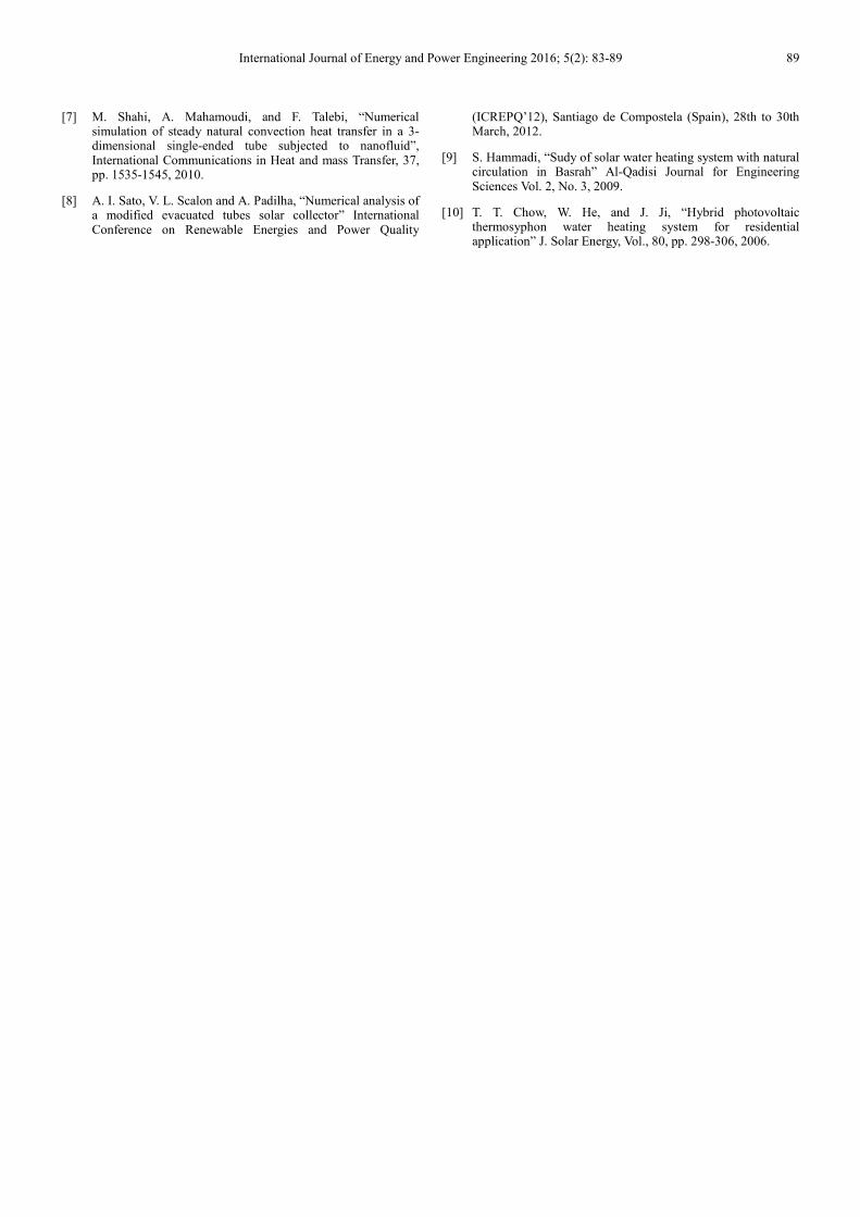
Figure 13. Comparison between model prediction and experimental data.
Figure 14. Comparison between model prediction and experimental data.
The water flowrates were measured with flow meters type
Hall effect model number YFG1 with precision +/- 3% of the
88 Samuel Sami et al.: Numerical Analysis of Thermosyphon Solar Water Heaters
flow rate in the range of 1-10 l/min. The solar intensity was
measured at the site using a HOBO ware software package
for HOBO data loggers.
It is quite clear from these figures that the water
temperature in the storage tank decreases as water is
evacuated from the tank and makeup city water is supplied to
the storage tank. It is also evident from the comparison
presented in these figures that the proposed model predicted
fairly the evacuation storage tank time variation temperature
at various initial temperatures of the water at the storage tank
and solar radiations as measured by the Hobo data
acquisition system. It can also be pointed out that the results
presented in these figures show minor discrepancies between
the predicted results and data which are attributed to heat
losses. The higher the storage tank temperature the higher the
heat losses.
The energy conversion efficiencies of the solar collector
were calculated using equations (12) and (13) and presented
in figure. 15, for various solar radiations and initial water
temperatures in the storage tank. The results illustrated, in
this figure, clearly show that higher solar radiation enhances
the solar collector energy conversion efficiency. Also as
shown, lower water temperature in the storage tank is
associated with higher efficiency. This is attributed to less
heat losses from the storage tank during the water heating
process.
Figure 15. Energy conversion efficiency of solar collector.
5. Conclusions
During the course of this study, modeling and simulation
as well as validation of a natural circulation closed
thermosyphon glass solar tube collector water heater have
been presented and discussed. Energy conservation equations
were written for heat transfer fluid flow from the storage, in
finite-difference form, integrated and solved to yield the
behavior of the thermosyphon system at different solar
insolations and water mass flow rate conditions as well as
water storage tank temperatures.
The results presented in this study showed that higher solar
radiation enhances the solar collector energy conversion
efficiency. It is quite evident from the comparison presented
in hereby that the proposed model predicted fairly the
evacuation storage tank time variation temperature at various
initial conditions of the water at the storage tank and solar
radiations.
Acknowledgement
The research work presented in this paper was made
possible through the support of the Catholic University of
Cuenca.
Nomenclature
A Collector area (m2)
d Diameter of glass solar tube
g Acceleration due to gravity (m/s2)
H Height of tank (m)
I Solar intensity (W/m2)
L Length of the collector (m)
m Water mass flow rate (kg/s)
N Number of tubes in the collector (–)
u Velocity (m/s)
T Temperature (°C)
t Time (hr)
Greek symbols
a Absorbitivity (-)
τα Effective transmittance-absorptance
ρ Water density (kg /m3)
β´ Coefficient of expansion of water (k-1)
ʋ Mean kinematics viscosity of water (m2/s)
Indices
c Collector
s Storage tank
o or i Outlet and Inlet of the collector, respectively
References
[1] Mahendra S. Seveda, “Performance analysis of solar water heater in NEH region of India”, International Journal of Renewable and Sustainable Energy, 2013; 2 (3): 93-98.
[2] O. B. Bukola, “Flow design and collector performance of a natural circulation solar water heater” Journal of Engineering and Applied Science, Vol. 1, Issue: 1, pp. 7-13, 2006.
[3] B. Sitzmann, “Solar Water Heater with Thermosyphon Circulation”, Appropriate Technology, Vol. 31, Issue: 1, pp. 66-70, 2004.
[4] D. J. Close, “The Performance of Solar Water Heaters with Natural Circulation”, Solar Energy, Vol. 6, Issue: 1, pp. 33-40, 1962.
[5] J. Huang, S. Pu, W. Gao, and Y. Que, “Experimental investigation on thermal performance of thermosyphon flat-plate solar water heater with a mantle heat exchanger”, Energy, Vol. 35, pp. 3563-3568, 2010.
[6] S. Abgo “Analysis of the performance profile of the NCERD thermosyphon solar water heater”, Journal of Energy in Southern Africa, Vol 22 No 2, May 2011.
International Journal of Energy and Power Engineering 2016; 5(2): 83-89 89
[7] M. Shahi, A. Mahamoudi, and F. Talebi, “Numerical simulation of steady natural convection heat transfer in a 3-dimensional single-ended tube subjected to nanofluid”, International Communications in Heat and mass Transfer, 37, pp. 1535-1545, 2010.
[8] A. I. Sato, V. L. Scalon and A. Padilha, “Numerical analysis of a modified evacuated tubes solar collector” International Conference on Renewable Energies and Power Quality
(ICREPQ’12), Santiago de Compostela (Spain), 28th to 30th March, 2012.
[9] S. Hammadi, “Sudy of solar water heating system with natural circulation in Basrah” Al-Qadisi Journal for Engineering Sciences Vol. 2, No. 3, 2009.
[10] T. T. Chow, W. He, and J. Ji, “Hybrid photovoltaic thermosyphon water heating system for residential application” J. Solar Energy, Vol., 80, pp. 298-306, 2006.
Recommended