FORM ON007Rev. 02/02/2011 -1-
INSPECTION GUIDE
P210/ROLLS-ROYCE ENGINE CONVERSION
DATE:_______________________ WORK ORDER NO.______________
REGISTRATION:_______________ ENGINE S/N:_________________
AIRCRAFT S/N:_______________ ENGINE TT:__________________
AIRFRAME TT:________________ HOBBS:______________________
OWNER:__________________________________
TYPE OF INSPECTION:_____________________
NOTE: WHEN DOING ANNUAL INSPECTION YOU MUST COMPLETEALL INSPECTIONS THROUGH 300-HOUR INSPECTION
GENERAL
GENERAL
Airworthiness Directive Compliance ___________
Placards required by Type Certificate data sheet ___________
FORM ON007Rev. 02/02/2011 -2-
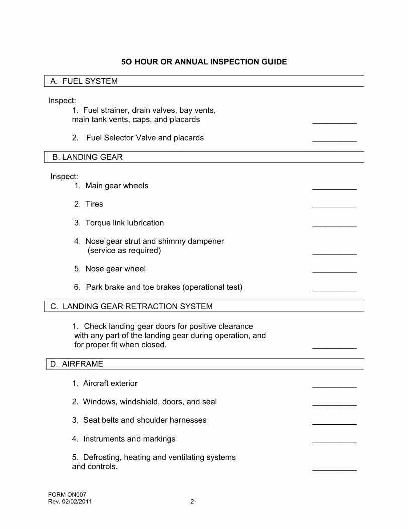
5O HOUR OR ANNUAL INSPECTION GUIDE
A. FUEL SYSTEM
Inspect:1. Fuel strainer, drain valves, bay vents,main tank vents, caps, and placards __________
2. Fuel Selector Valve and placards __________
B. LANDING GEAR
Inspect:1. Main gear wheels __________
2. Tires __________
3. Torque link lubrication __________
4. Nose gear strut and shimmy dampener(service as required) __________
5. Nose gear wheel __________
6. Park brake and toe brakes (operational test) __________
C. LANDING GEAR RETRACTION SYSTEM
1. Check landing gear doors for positive clearancewith any part of the landing gear during operation, andfor proper fit when closed. __________
D. AIRFRAME
1. Aircraft exterior __________
2. Windows, windshield, doors, and seal __________
3. Seat belts and shoulder harnesses __________
4. Instruments and markings __________
5. Defrosting, heating and ventilating systemsand controls. __________
FORM ON007Rev. 02/02/2011 -3-
50 HOUR OR ANNUAL INSPECTION GUIDE
D. AIRFRAME (Cont.)
6. Lights, switches, circuit breakers, fuses,and spare fuses __________
7. Exterior lights __________
8. Radios, radio controls, avionics, and flightinstruments __________
9. Battery and battery cables. Check electrolytelevel and clean battery each 50 hours or each
30 days __________
10. Oxygen supply - Inspect masks, hose and fittingsfor condition, routing and support __________
11. Seat Rails - inspect for cracks __________
12. Inspect rudder cable tension __________
E. CONTROL SYSTEMS
Always check for correct direction of movement,correct travel, and correct cable tension. Inspect:
1. Trim control wheels, indicators, actuator andbungee __________
2. Flap control switch, flap rollers, and flapposition indicator __________
3. Elevators, trim tab, hinges, and push-pulltube __________
4. External skins of control surfaces and tabs __________
5. Ailerons, hinges, and control rods __________
FORM ON007Rev. 02/02/2011 -4-
F. POWERPLANT
1. FUEL NOZZLE – Remove fuel nozzle and clean perRolls-Royce Maintenance ManualCAUTION: Do not remove fuel nozzle and igniter plugat the same time.After cleaning nozzle install fuel line and torque to80-120 in.- lbs. __________
2. IGNITER PLUG - Remove igniter plug andinspect. [74-20-01, para. 2.A]. __________
3. STARTER/GENERATOR - Remove rear cooling tubeand starter-generator shroud. Check brush wear perStarter Generator Maintenance Manual, and clean allcarbon dust from commentator and brush area withcompressed air. Reinstall air cooling tube. __________
1OO HOUR OR ANNUAL INSPECTION GUIDE
50-HOUR INSPECTION PLUS:
A. OPERATIONAL INSPECTION
1. BATTERY SWITCH - Check for proper operation.Check instruments for serviceability __________
2. STARTER - Check for proper operation.Starter must be able to rotate engine up to 15%before supplying fuel to combustion section. __________
3. CONDITION LEVER - Check for proper operation __________
4. POWER LEVER - Check for proper operation __________
5. N1 INDICATOR - Check for proper operation,readings, and fluctuations __________
6. TURBINE OUTLET TEMPERATURE (TOT) - Check forproper operation, temperature, and fluctuations __________
FORM ON007Rev. 02/02/2011 -5-
100 HOUR OR ANNUAL INSPECTION GUIDE
A. OPERATIONAL INSPECTION (Cont.)
150 HOURS
NOTE CALIBRATE THE ENGINE SUPPLIED THERMOCOUPLE ASSEMBLY
[77-20-01, para 2].
CALIBRATE THE TOT INDICATING SYSTEM IN ACCORDANCE WITHMANUFACTURER’S INSTRUCTIONS.
7. ENGINE OIL PRESSURE AND TEMPERATURE –Check for proper pressure, temperature limits, and unusualfluctuations __________
8. TORQUE PRESSURE - Check for normal readings andunusual fluctuations __________
9. AMMETER - Generator ON. Check for properindication and unusual fluctuations __________
10. PROPELLER DE-ICE - Check for proper operationand amperage draw on ammeter __________
11. IDLE RPM - Check for proper RPM and anyunusual fluctuations or instability __________
12. ALL ENGINE CONTROLS - Check for proper operationallimits, engine, and propeller response and rigging.Check friction locks for proper operation __________
13. FUEL QUANTITY GAGES - Check for proper operationand unusual fluctuations __________
14. FUEL TOTALIZER - Check for correct setting andproper operation __________
FORM ON007Rev. 02/02/2011 -6-
100 HOUR OR ANNUAL INSPECTION GUIDE
A. OPERATIONAL INSPECTION (Cont.)
15. FUEL PUMPS -- Check fuel pumps 1 and 2 forproper operation, unusual noise, or fluctuations __________
16. FUEL TANK SELECTION - Check for proper operationand positive detents in BOTH, L, and R positions __________
17. ALL LIGHTS - Check for condition, attachment,cracked, or broken lenses. Check switches,knobs, and circuit breakers for looseness andoperation __________
18. STALL WARNING SYSTEM - Check for proper operationand amperage draw on ammeter __________
19. HEATING & VENTILATING SYSTEMS - Checkfor proper operation, heat and air flow output. Checkcontrols for freedom of operation __________
20. RADIO OPERATION - Check for proper operationand security and switches and knobs __________
21. FLAPS -- Check for noisy operation, full travel,and proper indication __________
22. PITOT HEAT - Check amperage draw on ammeterand for proper heating of unit __________
23. FLIGHT INSTRUMENTS - Check for condition andproper operation __________
24. BRAKES - Check for condition and wear, ease ofoperation, and proper release of the parking brake.Check for unusual brake chatter. __________
25. EMERGENCY LOCATER TRANSMITTER - Check for properoperation and assure that the ELT is armed when the airplane isreturned to service __________
26. SWITCHES, CIRCUIT BREAKERS - Check for properoperation __________
FORM ON007Rev. 02/02/2011 -7-
100 HOUR OR ANNUAL INSPECTION GUIDE
A. OPERATIONAL INSPECTION (Cont.)
27. FLIGHT CONTROLS, TRIM CONTROLS, AND TRIMINDICATORS - Check freedom of movement andproper operation through full travel with and withoutflaps extended. Check electric trim controls for operation __________
28. ANTENNAS AND CABLES - Check for properoperation __________
B. POWERPLANT (*See Rolls-Royce 250-B17F Series Operationand Maintenance Manual for Referenced Sections
1. NACELLE SKIN - Check for deformation and obviousdamage or cracks. Check for loose or missing parts __________
2. NACELLE STRUCTURE - Check for cracks anddeformation. Check for loose or missing rivets orconcealed damage __________
3. COWLING - Check for condition and security.Check camlocks and oil access door __________
4. COWL FLAP - Check for travel, deformation, andsecurity. Inspect for cracks __________
5. BATTERY - Inspect for cleanliness, tight connections,and add distilled water to maintain a level 3/8 inch abovethe top of the separators. Inspect the vents and overflowtube for obstructions. Check for security and properattachment. Check for corrosion. Make certain the batteryis clean. Water or dirt on battery surfaces can cause thebattery to discharge.
ANNUAL INSPECTION ONLY: Perform Battery CapacityTest (See Attachment A) __________
6. PLUMBING - Inspect plumbing and associatedaccessories for condition (such as cracks andfraying) and attachment. Check plumbingclearance and secure against possible chafing. __________
FORM ON007Rev. 02/02/2011 -8-
100 HOUR OR ANNUAL INSPECTION GUIDE
B. POWERPLANT (Cont.)
7. ENGINE OIL TANK - Check for cracks, leaks, properfluid level, deformation, and security. __________
8. OIL COOLER - Check oil cooler, lines, and fittingsfor condition, security, chafing, and leaks. __________
9. PROPELLER AND MOUNTING BOLTS - Checkfor condition and security. Check the tip of the bladesfor evidence of lightning strikes. If there is evidence oflightning strikes, consult the propeller manufacturer,the engine manufacturer, and the airframe manufacturer.Inspect the blades for cracks, dents, nicks, scratches,erosion,corrosion, security, and movement in the hub __________
10. PROPELLER SPINNER - Check for deformation,security, and cracks __________
11. PROPELLER HUB - Check for cracks, excessivelyleaking seals, and condition __________
12. STARTER/GENERATOR - Remove rear cooling tubeand starter-generator shroud. Check brush wear perStarter Generator Maintenance Manual, and clean allcarbon dust from commentator and brush area withcompressed air. Reinstall air cooling tube. __________
13. EXHAUST SYSTEM - Check for cracks, deformation,leaks and security of clamps __________
14. FIREWALL - Check for wrinkles, damage, or cracks.Check all electrical and control access holes forproper sealing. __________
15. HOSE AND DUCTS - Check all fuel, oil, and airhoses or ducts for leakage, cracks, deteriorationand damage. Check fittings for security __________
FORM ON007Rev. 02/02/2011 -9-
100 HOUR OR ANNUAL INSPECTION GUIDE
B. POWERPLANT (Cont.)
16. ENGINE ACCESSORIES - Check for condition,security and leaks. Check wiring, hoses, andtubes, for chafing, security and leaks Fuel Pump __________ Fuel Controls __________ N2 Governor __________ Propeller Tachometer __________ Tachometer Generators __________ Vacuum Pump __________
17. ENGINE MOUNT FRAME - Check for cracks,corrosion, and security. Check mount pad bolts forloose or missing bolts and safety __________
18. ENGINE MOUNTS - Inspect rubber cushions forcracks, splits, separation, and deterioration.Check through bolts and nuts for condition andSecurity __________
19. ENGINE CONTROLS - Check controls and associatedequipment for condition, attachment, alignment, andrigging __________
20. FUEL CONTROL AND POWER TURBINE GOVERNORLINKAGE - Check for freedom of operation, full travel, andproper rigging. Check security of linkage and for loose orworn linkage and linkage bolts. [76-00-00, Par. 1A]. __________
21. ELECTRICAL WIRING AND EQUIPMENT - Inspectelectrical wiring and associated equipment andaccessories for fraying and attachment __________
22. ENGINE - Inspect the entire engine for looseor missing bolts, broken or loose connections,security of mounting accessories and brokenor missing lockwire. Check accessible areasfor obvious damage and evidence of fuel oroil leakage. __________
FORM ON007Rev. 02/02/2011 -10-
100 HOUR OR ANNUAL INSPECTION GUIDE
B. POWERPLANT - (Cont.)
23. ELECTRIC PROPELLER DE-ICEa) Check for service damage to the de-iceheaters, brush blocks, springs, and brushes.Check for attachment and security. __________
b) Check the lead straps and all otherclamps, connectors, and wiring for electricalsoundness, security, and attachment. __________
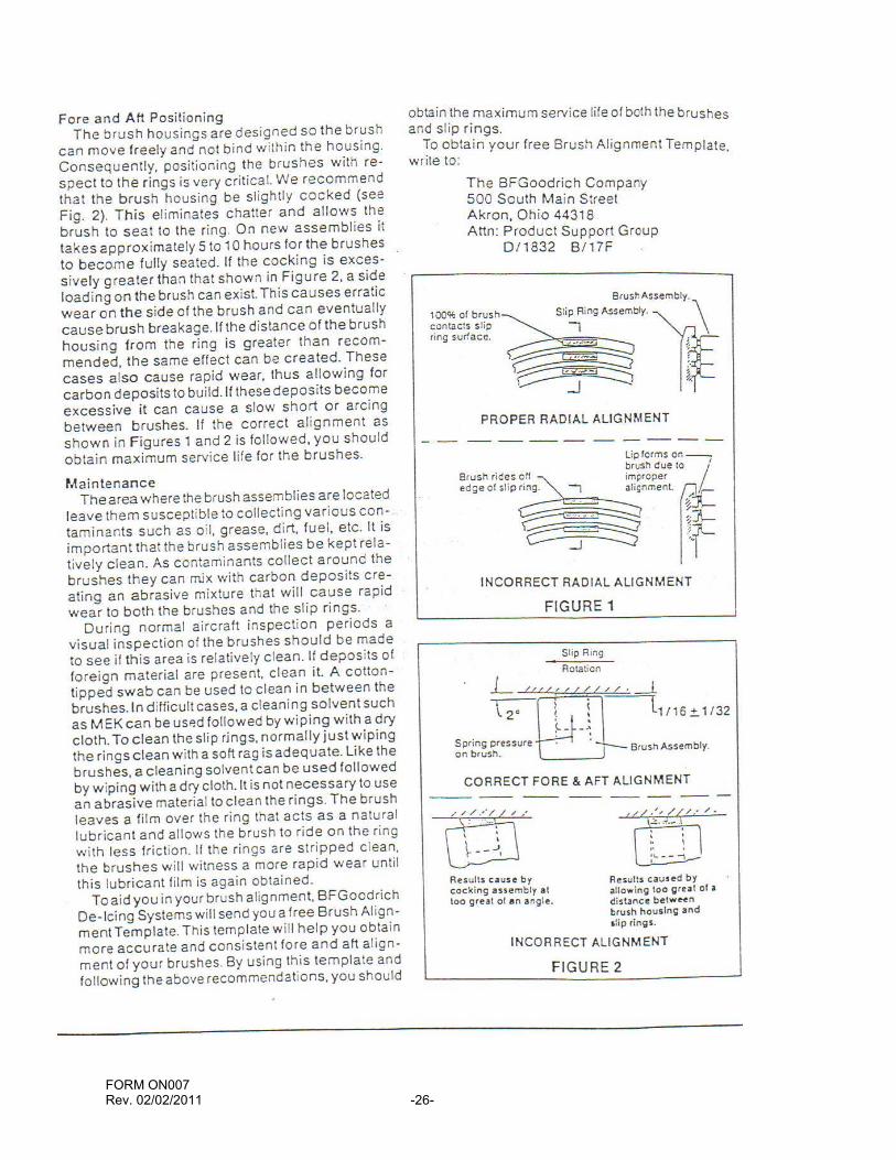
c) Check the slip rings for roughness, cracks,burned or discolored areas and for deposits ofoil, grease, or dirt. Check for security andattachment. See BFGoodrich Prop Tips(Attachment B) __________
d) Check de-ice boots for wrinkles, loose ortorn areas. __________
24. AIR INLET – (If equipped with electrical Style)Check inlet fairing for condition and security of attachment
and element wiring for security. Remove all foreign materialwhich might be drawn into the compressor inlet.
AIR INLET – (If equipped with Bleed-Air Heated Style)Check rubber seal for condition and security of attachment.Remove all foreign material which might be drawn intoCompressor inlet. __________
25. COMPRESSOR - Inspect compressor inlet guidevanes and visible blades and vanes for foreign objectdamage. __________
26. COMPRESSOR CLEANING - Clean compressor withchemical wash solution as required if operatingin a smoggy area [72-30-00, para 5-B] __________
27. COMPRESSOR SCROLL - Inspect thecompressor scroll for cracks or breaks at theanti-ice air valve and customer bleed ports. If cracksor breaks are found check engine for possiblecauses of vibration [72-00-00, para. 1-C(2)]. __________
FORM ON007Rev. 02/02/2011 -11-
100 HOUR OR ANNUAL INSPECTION GUIDE
B. POWERPLANT (Cont.)
28. Inspect Pc filter for proper clamping and security[73-20-03, para. 2-B]. __________
29. Using a 10x power glass, inspect the condition ofthe Pc filter and fitting for distress/cracks, andthe elbow in the scroll for distress/cracks/properalignment. No cracks are permissible in eitherthe Pc filter or the Compressor Scroll __________
30. Remove the Scroll-to-Pc Filter Tube Assembly andinspect for cracks using a 10x power glass. Payparticular attention to the flared ends of thetube for cracks, and to the areas beneath thefloating ferrules for fretting damage. Tubesfound to contain cracks and/or excessivefretting damage are to be replaced by new partsof the same part number as removed. __________
NOTEEXCESSIVE FRETTING IS PRESENT WHENTHE FERRULE HAS CHAFED THE TUBESUFFICIENTLY TO WEAR A STEP THATCAN BE FELT WITH A THUMBNAILOR OTHER INSPECTION AID.
31. AIR DISCHARGE TUBES - Inspect for excessivelooseness, inserts that are locked or backing out ofthe scroll. If locked or loose inserts are detected,check engine for possible causes of vibration. __________
32. ANTI-ICE VALVE - Check anti-ice valve forsecurity, worn parts, and proper operation.Valve need not be removed unless a problem isdetected [75-10-01, para. 2]. __________
33. COMPRESSOR MOUNT INSERTS - Check inserts forlooseness or oil leakage. Replace if loose andcheck engine for possible causes of vibration[72-60-00, para. 4.E & F]. __________
FORM ON007Rev. 02/02/2011 -12-
100 HOUR OR ANNUAL INSPECTION GUIDE
B. POWERPLANT (Cont.)
34. TURBINE SUPPORTS - Inspect the turbine supportassemblies and engine exhaust duct for conditionof welded joints, for cracks, and buckling[72-50-00, para. 8.A]. __________
35. TURBINE OIL PRESSURE CHECK VALVE – Inspectand clean the check valve [72-60-00, para. 2.J]. __________
36. TURBINE OIL PRESSURE TUBE SCREEN – Inspectand clean the tube screen. __________
37. SCAVENGE OIL FLOW - Measure the oil flow fromscavenge passage and external sump of the powerturbine support [72-50-00, para. 6.D]. __________
FLOW AMOUNT P.T._____________cc (Min 90cc)G.P._____________cc (Min 75cc)
38. MAGNETIC DRAIN PLUGS - Inspect, clean, andcheck magnetic drain plugs [72-00-00, para. 10.H]. __________
39. Inspect the start counter for proper operation(increase in count) and for loose, chafed,frayed, or broken wires and loose connectors. __________
40. Check the condition of the bleed valve gasket(without removing bleed valve). Replace gasketif air leaks (blowouts) can be detected. __________
41. COMBUSTION CASE - Inspect the outer combustioncase for condition. Inspect the weld joints ofcases that do not have the brazed screenreinforcement in the armpit area [72-40-00, par 2.B]. __________
42. BURNER DRAIN VALVE - Clean the burner drainvalve [72-40-00, para. 3.A].
__________
FORM ON007Rev. 02/02/2011 -13-
100 HOUR OR ANNUAL INSPECTION GUIDE
B. POWERPLANT (Cont.)
43. IGNITION LEAD - Inspect the ignition lead forburning, chafing, or cracking of conduit and looseconnections and broken lockwire [74-20-02, para. 02]. __________
44. IGNITER PLUG - Remove igniter plug andinspect. [74-20-01, para. 2.A]. __________
45. EXTERNAL SCAVENGE OIL FILTER - Check filterbypass warning indicator for bypass condition __________
46. FUEL NOZZLE – Remove fuel nozzle and clean perRolls-Royce Maintenance ManualCAUTION: Do not remove fuel nozzle and igniter plugat the same time.After cleaning nozzle install fuel line and torque to80-120 in.- lbs. __________
C. FUEL SYSTEM
Check fuel lines and check valve [Beginning withP21000390 and earlier aircraft modified by SK210-93,check that the fuel line insulation in the nose geartunnel is in good condition.] __________
D. LANDING GEAR
1. MAIN GEAR STRUT-TO-PIVOT ATTACHMENT – Check __________
2. SPRINGS - check condition of all springs. __________
3. POWER PACK CHECK VALVE SCREEN - Clean. __________
E. ENGINE RECORDS
1. Review engine records for time or cyclelimited parts, components, accessories, or modules __________
2. Review engine records for compliance withall mandatory bulletins, inspections, andairworthiness directives __________
FORM ON007Rev. 02/02/2011 -14-
100 HOUR OR ANNUAL INSPECTION GUIDE
B. POWERPLANT (Cont.)
3. Enter component changes, inspectioncompliance, etc. in log book as required __________
*Note 1 REFER TO TABLE 602 AND TABLE III-9 of Rolls-Royce 250-B17 SeriesOperation and Maintenance Manual for details of this inspection procedure.
2OO HOUR INSPECTION GUIDEOR
ANNUAL INSPECTION GUIDE
100-HOUR INSPECTION PLUS:
A. FUEL SYSTEM
1. Check fuel reservoirs for cracks and leaking __________
2. Check fuel drains and sump drains __________
[Compliance with Cessna Single Engine CustomerCare, Service Information Letter SE82-36 __________
B. LANDING GEAR
1. Check brake fluid, lines, hoses, linings, disk __________
2. Check main gear springs __________
3. Inspect parking brake system __________
4. Inspect nose gear fork __________
5. Inspect nose gear steering system __________
FORM ON007Rev. 02/02/2011 -15-
C. LANDING GEAR RETRACTION SYSTEM
NOTEWHEN PERFORMING AN INSPECTION OF THE LANDINGGEAR RETRACTION SYSTEM, THE AIRCRAFT MUST BE
PLACED ON JACKS AND AN EXTERNAL ELECTRICALPOWER SOURCE OF AT LEAST 60-A SHOULD BE USED
TO PREVENT DRAIN ON THE AIRCRAFT BATTERY WHILEOPERATING THE SYSTEM.
1. Operate the landing gear through fivefault-free cycles __________
2. Check all hydraulic system components forsecurity, hydraulic leaks, and any apparent damageto components or mounting structure __________
200 HOUR OR ANNUAL INSPECTION
C. LANDING GEAR RETRACTION SYSTEM (Cont.)
3. Check doors, hinges, hinge pins and linkagefor evidence of wear, other damage, and securityof attachment. __________
4. Inspect internal wheel well and tunnel structurefor cracks, dents, loose rivets, bolts, andnuts, corrosion and other damage. __________
5. Check electrical wiring and switches for securityof connections, switch operation, and check gearposition indicator lights for proper operation.Check wiring for proper routing and support. __________
6. Perform operational check and ensure properrigging of all systems and components includingdownlocks, uplocks, doors, switches, actuators,and power pack (observing cycle time). __________
FORM ON007Rev. 02/02/2011 -16-
200 HOUR OR ANNUAL INSPECTION
D. AIRFRAME (Cont.)
Inspect:1. Aircraft structure __________
2. Seat stops, seat rails, upholstery, structureand mounting __________
3. Control column bearings, sprockets, pulleys,cables, chains and turnbuckles __________
4. Control lock, control wheel, and controlcolumn mechanism __________
5. Gyros central air filter __________
6. Instrument wiring and plumbing __________
7. Instrument panel, shock mounts, groundstraps, cover, decals and labeling __________
8. Cabin upholstery, trim, sun visors, and ashtrays __________
9. Area beneath floor, lines, hoses, wires andcontrol cables __________
10.Pitot and static systems __________
11. Stall warning unit and pitot heater __________
12.Oxygen system __________
13.De-ice system plumbing __________
14.De-ice system components __________
15.De-ice system boots __________
FORM ON007Rev. 02/02/2011 -17-
E. CONTROL SYSTEMS
NOTEIN ADDITION TO THE ITEMS LISTED BELOW, ALWAYS
CHECK FOR CORRECT DIRECTION OF MOVEMENT, CORRECTTRAVEL, AND CORRECT CABLE TENSION
Inspect:1. Cables, terminals, pulleys, pulley brackets,cable guards, turnbuckles, and fairleads __________
2. Chains, terminals, sprockets, and chainguards __________
3. Travel stops __________
4. Decals and labeling __________
5. Flap motor, transmission, limit switches,structure, linkage, bellcranks, etc __________
6. Rudder pedal assemblies and linkage __________
7. Internal structure of control surfaces __________
300 HOUR OR ANNUAL INSPECTION
1OO-HOUR AND 2OO-HOUR INSPECTIONS PLUS:
A. ENGINE
CAUTION: If Firewall Shutoff is pulled to accomplish fuelFilter change, you must loosen line on engine driven pumpWithin 10 minutes or fuel pressure gauge in cockpit willBe damaged.
1. OIL SYSTEM - Drain oil system and refill.Remove, clean, and reinstall the oil filterand magnetic drain plugs. Drain oil coolerand reinstall plug. __________
2. SCAVENGE FILTER - Install new filter(FACET P/N 038088-08) __________
FORM ON007Rev. 02/02/2011 -18-
300 HOUR OR ANNUAL INSPECTION
A. ENGINE (Cont.)
3. COMPRESSOR CASE - Inspect the compressorCase when operating in an erosive or corrosive environment __________
EVERY 300 HOURS: Perform Compressor Half RemovalAnd Inspection [72-30-00] __________
4. FUEL FILTER - If the aircraft is equippedwith an engine fuel filter differential pressure warningsystem, replace the throw-away filter only when anindication of contamination is obtained or every 300hours, whichever occurs first. __________
NOTE
WHEN THERE IS EVIDENCE THAT THE FUEL PUMPFILTER HAS BYPASSED, THE GAS PRODUCER
FUEL CONTROL STRAINER ASSEMBLYMUST BE CLEANED.
5. FUEL FILTER BYPASS VALVE -- Perform a bypassvalve operational check whenever a fuel filter is replaced. __________
6. FUEL FILTER ELEMENT - Replace the airframemounted fuel filter element (Facet P/N 1737800) __________
7. TURBINE SCAVENGE OIL SYSTEM -[72-50-00]
a) Visually inspect external sump. Cleaninternal carbonaceous deposits from sump __________
b) Inspect the power turbine supportscavenge strut. Clean internal carbonaceousdeposits from strut. __________
8. FUEL FILTER BOWL - Purge air from bowl areaafter filter inspection or replacement. Remove line onengine fuel pump and drain until there are no bubblescoming from the line; squeeze line on pump whencompleted __________
FORM ON007Rev. 02/02/2011 -19-
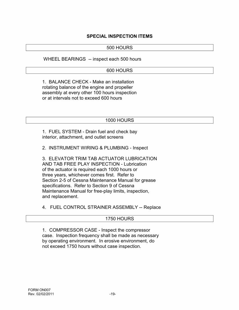
SPECIAL INSPECTION ITEMS
500 HOURS
WHEEL BEARINGS -- inspect each 500 hours
600 HOURS
1. BALANCE CHECK - Make an installationrotating balance of the engine and propellerassembly at every other 100 hours inspectionor at intervals not to exceed 600 hours
1000 HOURS
1. FUEL SYSTEM - Drain fuel and check bayinterior, attachment, and outlet screens
2. INSTRUMENT WIRING & PLUMBING - Inspect
3. ELEVATOR TRIM TAB ACTUATOR LUBRICATIONAND TAB FREE PLAY INSPECTION - Lubricationof the actuator is required each 1000 hours orthree years, whichever comes first. Refer toSection 2-5 of Cessna Maintenance Manual for greasespecifications. Refer to Section 9 of CessnaMaintenance Manual for free-play limits, inspection,and replacement.
4. FUEL CONTROL STRAINER ASSEMBLY -- Replace
1750 HOURS
1. COMPRESSOR CASE - Inspect the compressorcase. Inspection frequency shall be made as necessaryby operating environment. In erosive environment, donot exceed 1750 hours without case inspection.
FORM ON007Rev. 02/02/2011 -20-
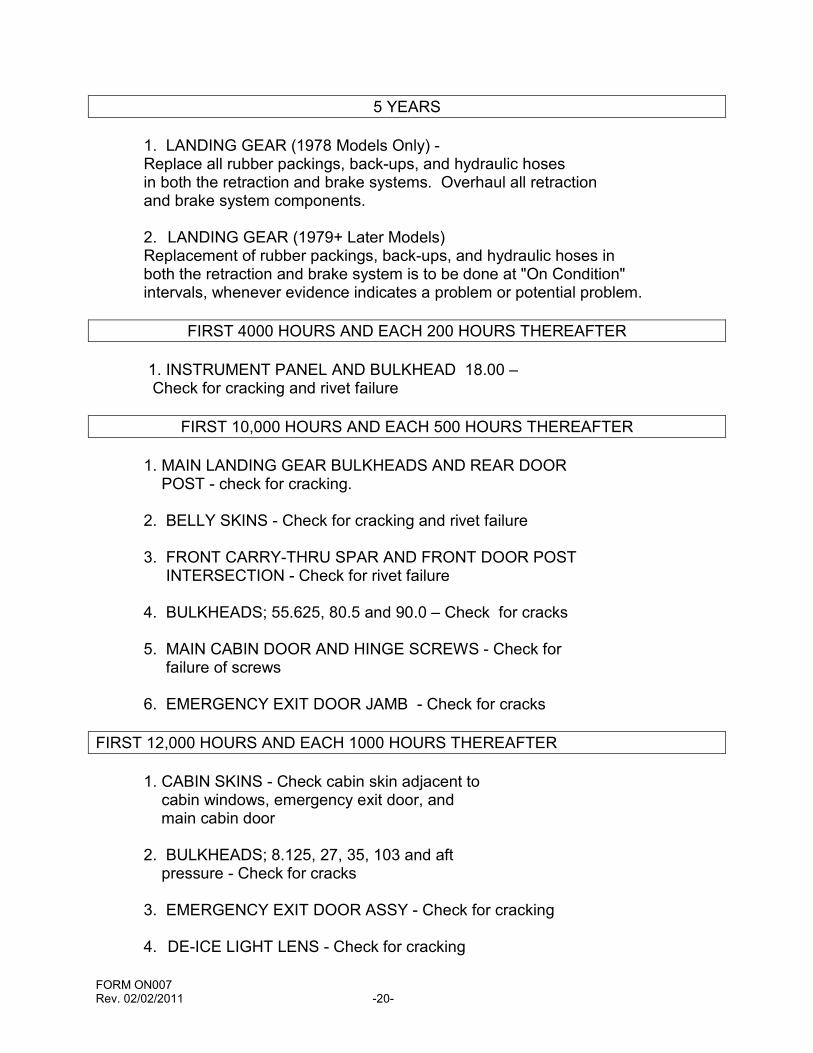
5 YEARS
1. LANDING GEAR (1978 Models Only) -Replace all rubber packings, back-ups, and hydraulic hosesin both the retraction and brake systems. Overhaul all retractionand brake system components.
2. LANDING GEAR (1979+ Later Models)Replacement of rubber packings, back-ups, and hydraulic hoses inboth the retraction and brake system is to be done at "On Condition"intervals, whenever evidence indicates a problem or potential problem.
FIRST 4000 HOURS AND EACH 200 HOURS THEREAFTER
1. INSTRUMENT PANEL AND BULKHEAD 18.00 –Check for cracking and rivet failure
FIRST 10,000 HOURS AND EACH 500 HOURS THEREAFTER
1. MAIN LANDING GEAR BULKHEADS AND REAR DOORPOST - check for cracking.
2. BELLY SKINS - Check for cracking and rivet failure
3. FRONT CARRY-THRU SPAR AND FRONT DOOR POSTINTERSECTION - Check for rivet failure
4. BULKHEADS; 55.625, 80.5 and 90.0 – Check for cracks
5. MAIN CABIN DOOR AND HINGE SCREWS - Check forfailure of screws
6. EMERGENCY EXIT DOOR JAMB - Check for cracks
FIRST 12,000 HOURS AND EACH 1000 HOURS THEREAFTER
1. CABIN SKINS - Check cabin skin adjacent tocabin windows, emergency exit door, andmain cabin door
2. BULKHEADS; 8.125, 27, 35, 103 and aftpressure - Check for cracks
3. EMERGENCY EXIT DOOR ASSY - Check for cracking
4. DE-ICE LIGHT LENS - Check for cracking

FORM ON007Rev. 02/02/2011 -21-
OVERHAUL AND REPLACEMENT SCHEDULE
POWERPLANT
MODULAR OVERHAUL
Component TBO (Hr) HMI (Hr)
Compressor 3500 NoneGearbox On condition NoneTurbine 3500 17501
Propeller ReductionGearbox, P/N 23050802 On condition NonePropeller ReductionGearbox, P/N 23033880 2200 None
SECTIONALIZED OVERHAUL – ACCESSORIES
Accessories Recommended Time Between Overhauls (Hours)
Component Recommended TBOFuel Pump - Sundstrand 2250Fuel Pump – Argo-Tech (TRW)P/N 386500-5 4000P/N 386500-1 -2 -3 -4 3500CECO (RR P/N 23070459) 3500P/N 113300-03A1 (CECO P/N0Fuel Control 2500Woodward Combined Governor 2000Woodward Propeller Overspeed Governor 1750Fuel Nozzle 2500Bleed Valve 1500
1 ) Refer to Chapter 05 [Rolls-Royce Operation & Maintenance Manual] for life limits ofcertain rotating parts. It is the responsibility of the operator to assure that the life limitsare never exceeded.
FORM ON007Rev. 02/02/2011 -22-
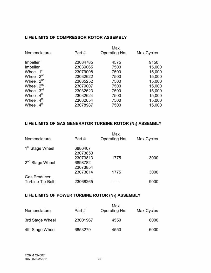
LIFE LIMITS OF COMPRESSOR ROTOR ASSEMBLY
Max.Nomenclature Part # Operating Hrs Max Cycles
Impeller 23034785 4575 9150Impeller 23039065 7500 15,000Wheel, 1st 23079008 7500 15,000Wheel, 2nd 23032622 7500 15,000Wheel, 2nd 23035252 7500 15,000Wheel, 2nd 23079007 7500 15,000Wheel, 3rd 23032623 7500 15,000Wheel, 4th 23032624 7500 15,000Wheel, 4th 23032654 7500 15,000Wheel, 4th 23078987 7500 15,000
LIFE LIMITS OF GAS GENERATOR TURBINE ROTOR (N1) ASSEMBLY
Max.Nomenclature Part # Operating Hrs Max Cycles
1st Stage Wheel 68864072307385323073813 1775 3000
2nd Stage Wheel 68987822307385423073814 1775 3000
Gas ProducerTurbine Tie-Bolt 23068265 ------ 9000
LIFE LIMITS OF POWER TURBINE ROTOR (N2) ASSEMBLY
Max.Nomenclature Part # Operating Hrs Max Cycles
3rd Stage Wheel 23001967 4550 6000
4th Stage Wheel 6853279 4550 6000
FORM ON007Rev. 02/02/2011 -23-
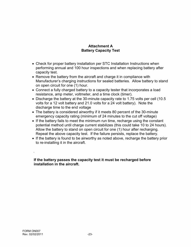
Attachment ABattery Capacity Test
Check for proper battery installation per STC Installation Instructions whenperforming annual and 100 hour inspections and when replacing battery aftercapacity test.
Remove the battery from the aircraft and charge it in compliance withManufacturer’s charging instructions for sealed batteries. Allow battery to standon open circuit for one (1) hour.
Connect a fully charged battery to a capacity tester that incorporates a loadresistance, amp meter, voltmeter, and a time clock (timer).
Discharge the battery at the 30-minute capacity rate to 1.75 volts per cell (10.5volts for a 12 volt battery and 21.0 volts for a 24 volt battery). Note thedischarge time to the end voltage
The battery is considered airworthy if it meets 80 percent of the 30-minuteemergency capacity rating (minimum of 24 minutes to the cut off voltage)
If the battery fails to meet the minimum run time, recharge using the constantpotential method until charge current stabilizes (this could take 10 to 24 hours).Allow the battery to stand on open circuit for one (1) hour after recharging.Repeat the above capacity test. If the failure persists, replace the battery.
If the battery is found to be airworthy as noted above, recharge the battery priorto re-installing it in the aircraft.
.
If the battery passes the capacity test it must be recharged beforeinstallation in the aircraft.
FORM ON007Rev. 02/02/2011 -24-
Attachment BPropeller De-Icing Tips
FORM ON007Rev. 02/02/2011 -25-
FORM ON007Rev. 02/02/2011 -26-
Recommended


![arXiv:1407.0927v1 [cs.SE] 3 Jul 2014Landing-Gear Extended Landing-Gear Retracted Landing-Gear Box Landing Wheel Door Figure 1: Landing Gear System such as airport runways [11]. Three](https://img.pdfslide.us/doc/110x75/5e9397289f16a23cdf089611/arxiv14070927v1-csse-3-jul-2014-landing-gear-extended-landing-gear-retracted.jpg)

![Landing Gear Accessories - goldlinequalityparts.com€¦ · 12 Landing Gear Accessories Landing Gear Accessories 13 [254.0mm] 10.00" [254.0mm] 10.00" [111.3mm] 4.38" [304.8mm] 12.00"](https://img.pdfslide.us/doc/110x75/5f42201687106b11477aac9b/landing-gear-accessories-12-landing-gear-accessories-landing-gear-accessories.jpg)