NOR 2018-18 – V02 – 09JUL18 – 787 Briefing
Norwegian Boeing 787-8/9 Dreamliner
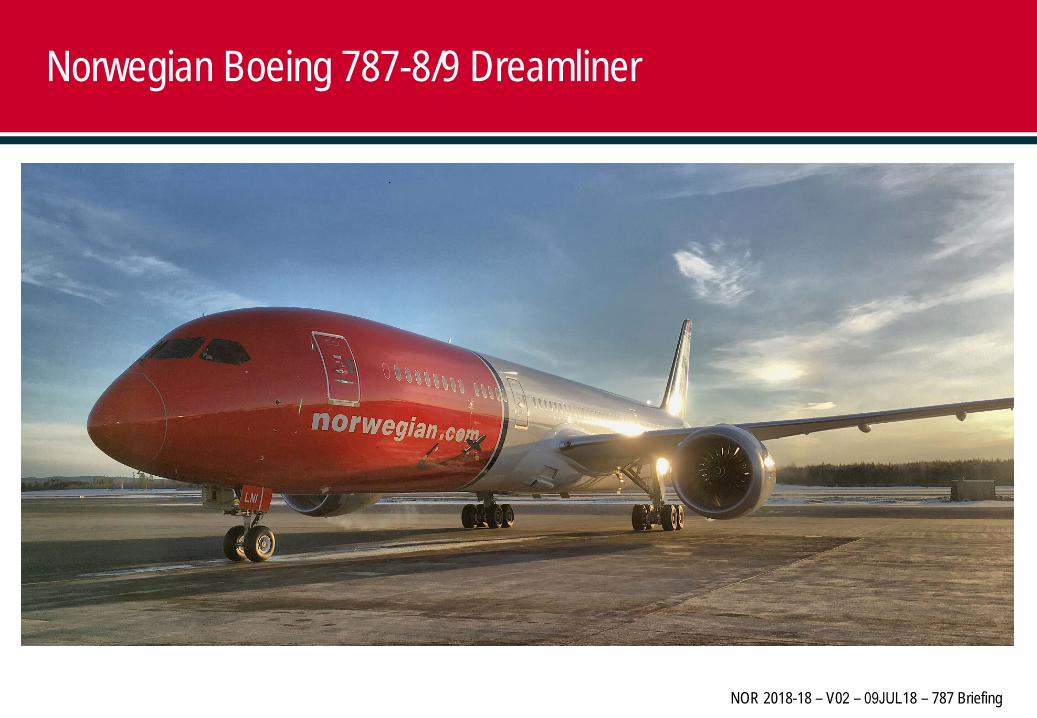
Composites50%
Aluminum20%
Titanium15%
Steel10%
Other5%
Carbon laminateCarbon sandwichOther compositesAluminumTitaniumTitanium/steel/aluminum
Aircraft Construction Materials
2
The Boeing 787 makes greater use of composite materials in its airframe and primary structure than any previous Boeing commercial airplane. Undertaking the design process without preconceived ideas enabled Boeing engineers to specify the optimum material for specific applications throughout the airframe.The result is an airframe comprising nearly half carbon fiber reinforced plastic and other composites. This approach offers weight savings on average of 20 percent compared to more conventional aluminum designs.Selecting the optimum material for a specific application meant analyzing every area of the airframe to determine the best material, given the operating environment and loads that a component experiences over the life of the airframe. For example, aluminum is sensitive to tension loads but handles compression very well. On the other hand, composites are not as efficient in dealing with compression loads but are excellent at handling tension. The expanded use of composites, especially in the highly tension-loaded environment of the fuselage, greatly reduces maintenance due to fatigue when compared with an aluminum structure. Titanium can withstand comparable loads better than aluminum, has minimal fatigue concerns, and is highly resistant to corrosion. Titanium use has been expanded on the 787 to roughly 14 percent of the total airframe.
Carbon Fiber Hidden Damage
3
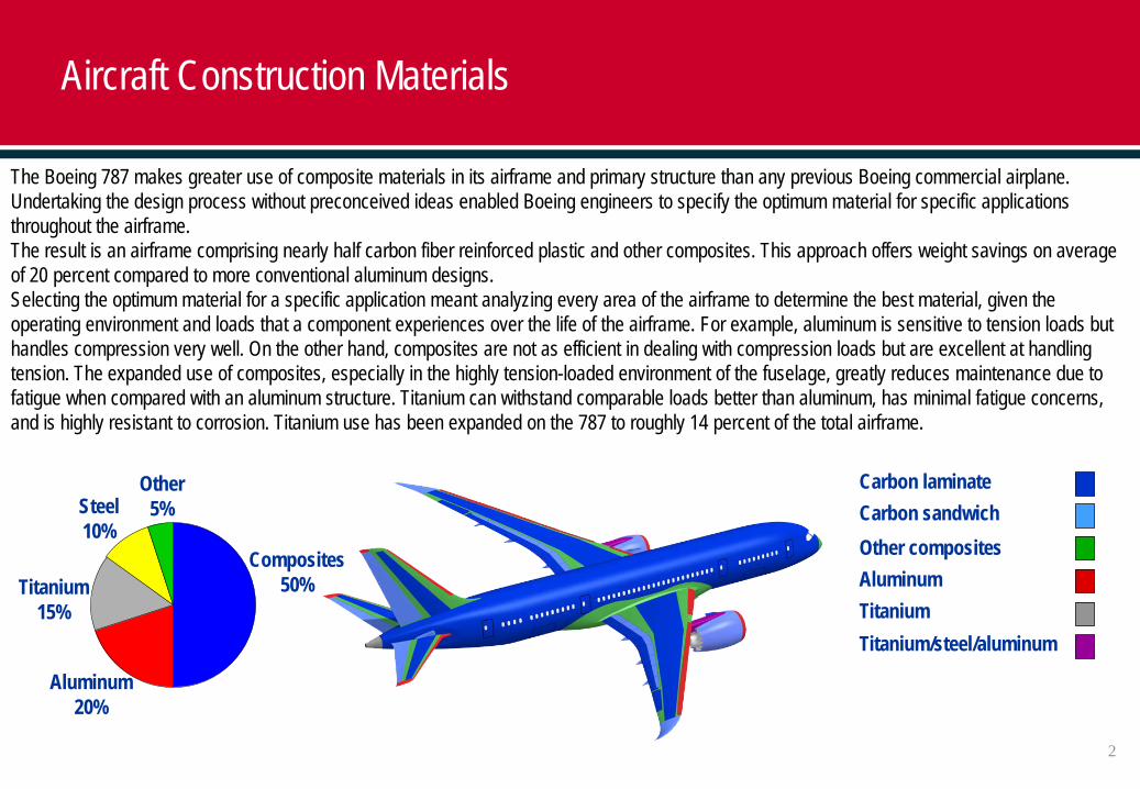
Reporting of damage or any form of contact with the aircraft is critical as damage may not be visually detected as easily as on an aluminum aircraft. Although there may not be visible damage externally there is a possibility of delaminating occurring internally. Any contact with the aircraft, no matter how small and any marks or paint damage, MUST be reported immediately in order to have qualified engineers assess the damage using a special testing device.
4
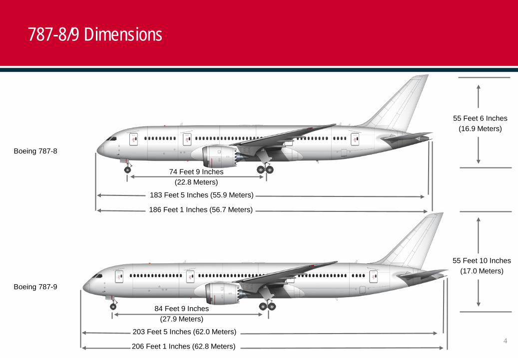
787-8/9 Dimensions
74 Feet 9 Inches (22.8 Meters)
183 Feet 5 Inches (55.9 Meters)
186 Feet 1 Inches (56.7 Meters)
84 Feet 9 Inches (27.9 Meters)
203 Feet 5 Inches (62.0 Meters)
206 Feet 1 Inches (62.8 Meters)
Boeing 787-8
Boeing 787-9
55 Feet 10 Inches (17.0 Meters)
55 Feet 6 Inches (16.9 Meters)
5
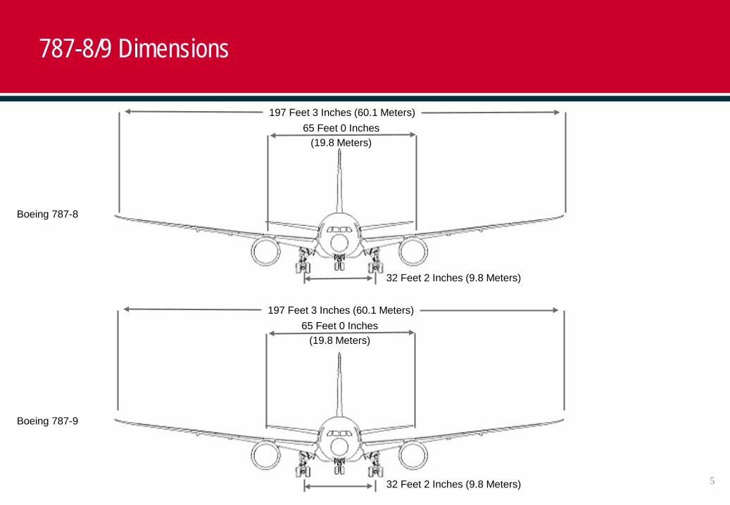
787-8/9 Dimensions
65 Feet 0 Inches (19.8 Meters)
197 Feet 3 Inches (60.1 Meters)
65 Feet 0 Inches (19.8 Meters)
197 Feet 3 Inches (60.1 Meters)
Boeing 787-8
Boeing 787-9
32 Feet 2 Inches (9.8 Meters)
32 Feet 2 Inches (9.8 Meters)
6
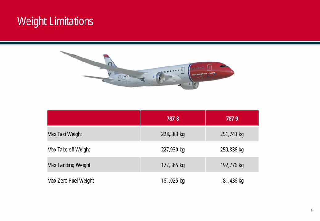
Weight Limitations
787-8 787-9
Max Taxi Weight 228,383 kg 251,743 kg
Max Take off Weight 227,930 kg 250,836 kg
Max Landing Weight 172,365 kg 192,776 kg
Max Zero Fuel Weight 161,025 kg 181,436 kg
7
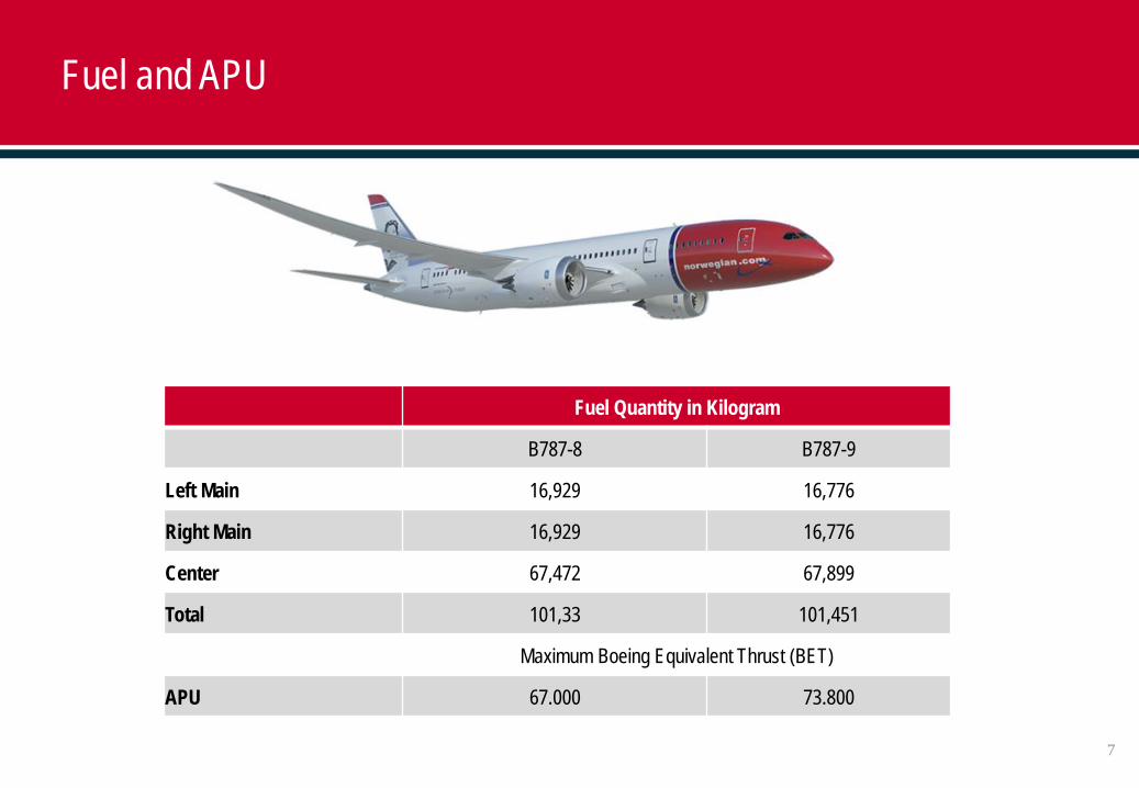
Fuel and APU
Fuel Quantity in Kilogram
B787-8 B787-9
Left Main 16,929 16,776
Right Main 16,929 16,776
Center 67,472 67,899
Total 101,33 101,451
Maximum Boeing Equivalent Thrust (BET)
APU 67.000 73.800
8
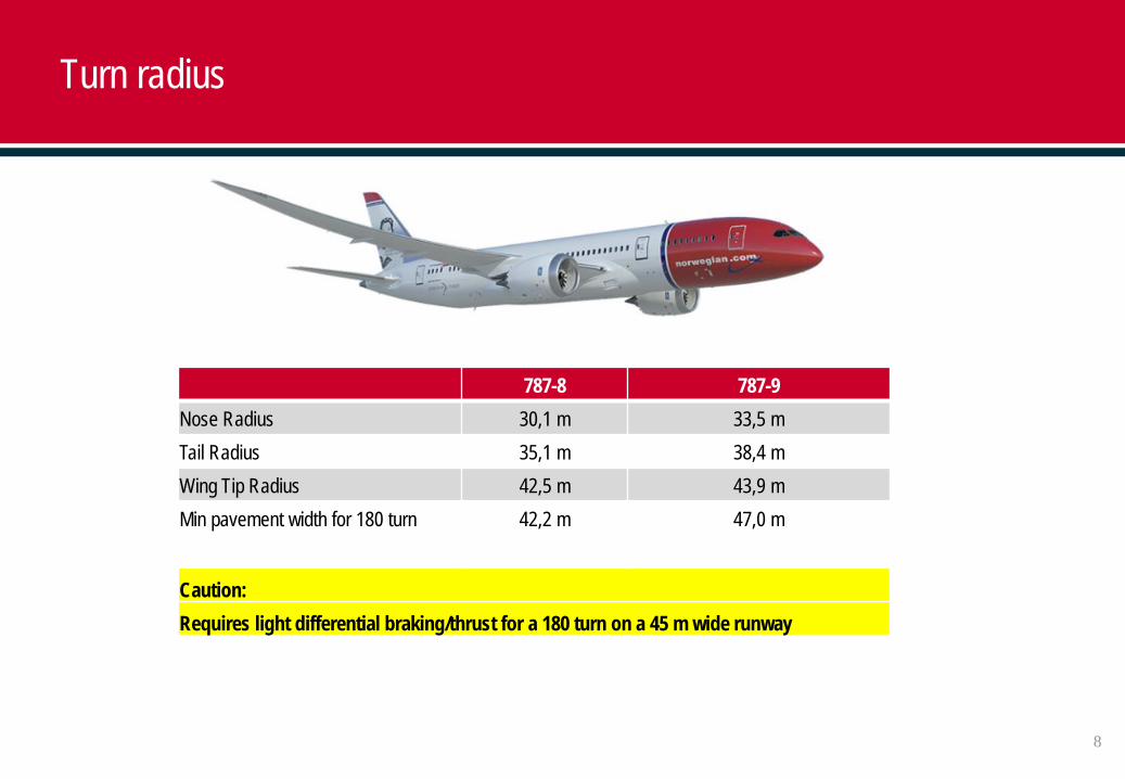
Turn radius
787-8 787-9Nose Radius 30,1 m 33,5 mTail Radius 35,1 m 38,4 mWing Tip Radius 42,5 m 43,9 mMin pavement width for 180 turn 42,2 m 47,0 m
Caution: Requires light differential braking/thrust for a 180 turn on a 45 m wide runway
9
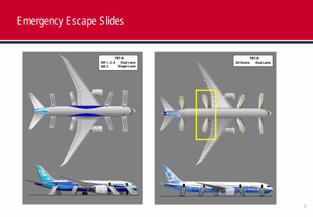
Emergency Escape Slides
10
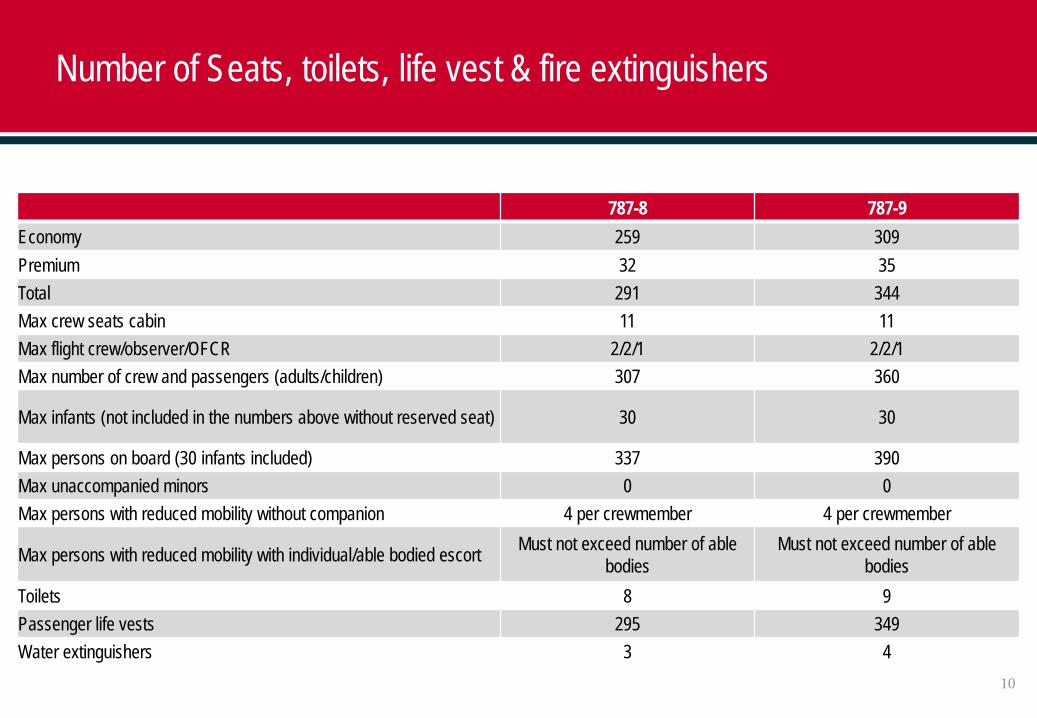
Number of Seats, toilets, life vest & fire extinguishers
787-8 787-9Economy 259 309Premium 32 35Total 291 344Max crew seats cabin 11 11Max flight crew/observer/OFCR 2/2/1 2/2/1Max number of crew and passengers (adults/children) 307 360
Max infants (not included in the numbers above without reserved seat) 30 30
Max persons on board (30 infants included) 337 390Max unaccompanied minors 0 0Max persons with reduced mobility without companion 4 per crewmember 4 per crewmember
Max persons with reduced mobility with individual/able bodied escort Must not exceed number of able bodies
Must not exceed number of able bodies
Toilets 8 9Passenger life vests 295 349Water extinguishers 3 4
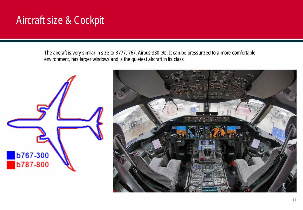
The aircraft is very similar in size to B777, 767, Airbus 330 etc. It can be pressurized to a more comfortable environment, has larger windows and is the quietest aircraft in its class
Aircraft size & Cockpit
11
12
Jet bridge
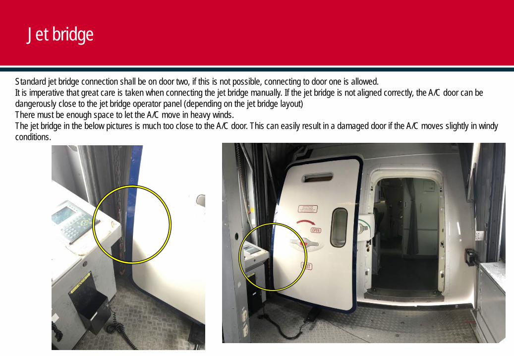
Standard jet bridge connection shall be on door two, if this is not possible, connecting to door one is allowed.It is imperative that great care is taken when connecting the jet bridge manually. If the jet bridge is not aligned correctly, the A/C door can be dangerously close to the jet bridge operator panel (depending on the jet bridge layout)There must be enough space to let the A/C move in heavy winds.The jet bridge in the below pictures is much too close to the A/C door. This can easily result in a damaged door if the A/C moves slightly in windy conditions.
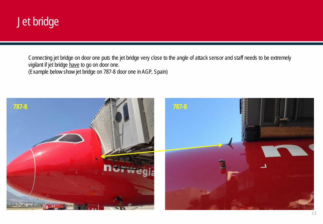
Connecting jet bridge on door one puts the jet bridge very close to the angle of attack sensor and staff needs to be extremely vigilant if jet bridge have to go on door one. (Example below show jet bridge on 787-8 door one in AGP, Spain)
787-8 787-8
Jet bridge
13
Jet bridge
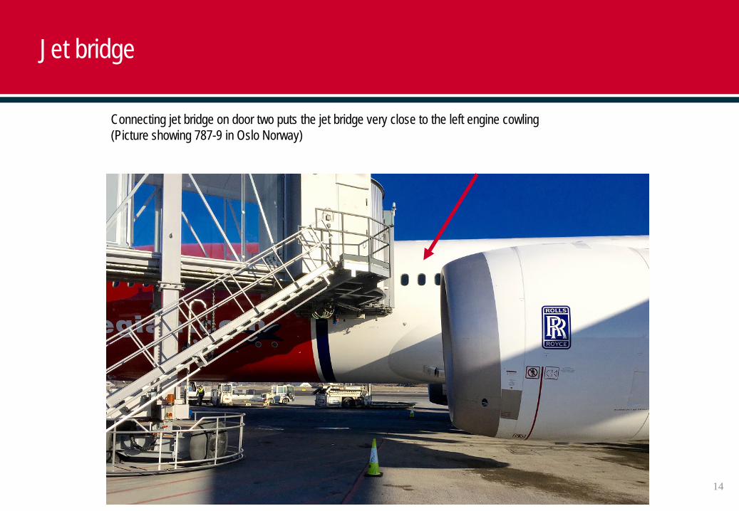
Connecting jet bridge on door two puts the jet bridge very close to the left engine cowling(Picture showing 787-9 in Oslo Norway)
14
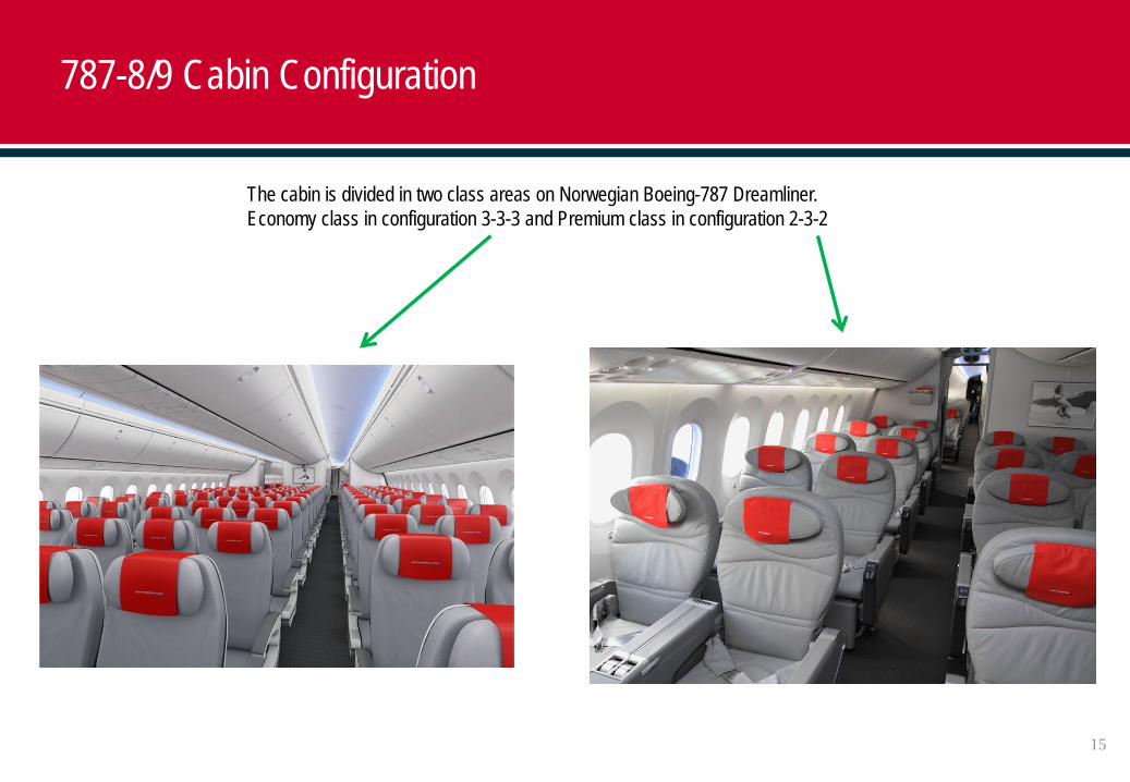
The cabin is divided in two class areas on Norwegian Boeing-787 Dreamliner. Economy class in configuration 3-3-3 and Premium class in configuration 2-3-2
787-8/9 Cabin Configuration
15
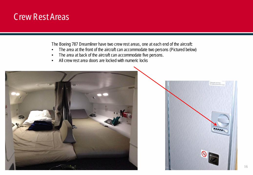
Crew Rest Areas
The Boeing 787 Dreamliner have two crew rest areas, one at each end of the aircraft: • The area at the front of the aircraft can accommodate two persons (Pictured below)• The area at back of the aircraft can accommodate five persons.• All crew rest area doors are locked with numeric locks
16

787-8/9 Aircraft Doors
17
1 2 3 4
5 6 7
Location 1 2 3 4 5 6 7
Door Passenger entry door 1(left side)
Passenger entry door 2(left side)
Passenger entry door 3(left side)
Passenger entry door 4(left side)
Forward cargo door(right side)
Aft cargo door(right side)
BulkCargo door(left side)
Maximum ground heights787-8
185.5 in(471.2 cm)
185.2 in(470.4 cm)
188.4 in478.5 cm
194.2 in(493.3 cm)
108.2 in(274.8 cm)
114.4 in(290.4 cm)
118.9 in(302.0 cm)
Maximum ground heights787-9
189 in(480 cm)
189 in(480 cm)
192.2 in488 cm
200 in(508 cm)
111 in(282 cm)
118.9 in(302 cm)
120.1 in(305 cm)
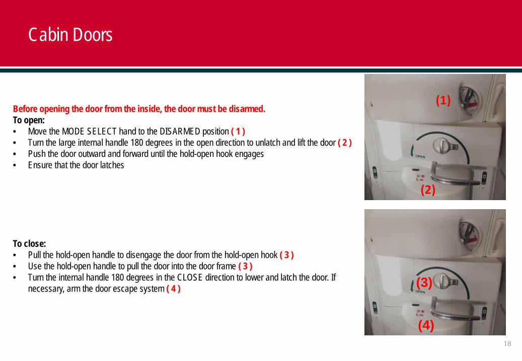
Before opening the door from the inside, the door must be disarmed.To open:• Move the MODE SELECT hand to the DISARMED position ( 1 )• Turn the large internal handle 180 degrees in the open direction to unlatch and lift the door ( 2 )• Push the door outward and forward until the hold-open hook engages• Ensure that the door latches
To close:• Pull the hold-open handle to disengage the door from the hold-open hook ( 3 )• Use the hold-open handle to pull the door into the door frame ( 3 )• Turn the internal handle 180 degrees in the CLOSE direction to lower and latch the door. If
necessary, arm the door escape system ( 4 )
(1)
(2)
Cabin Doors
18
(3)
(4)
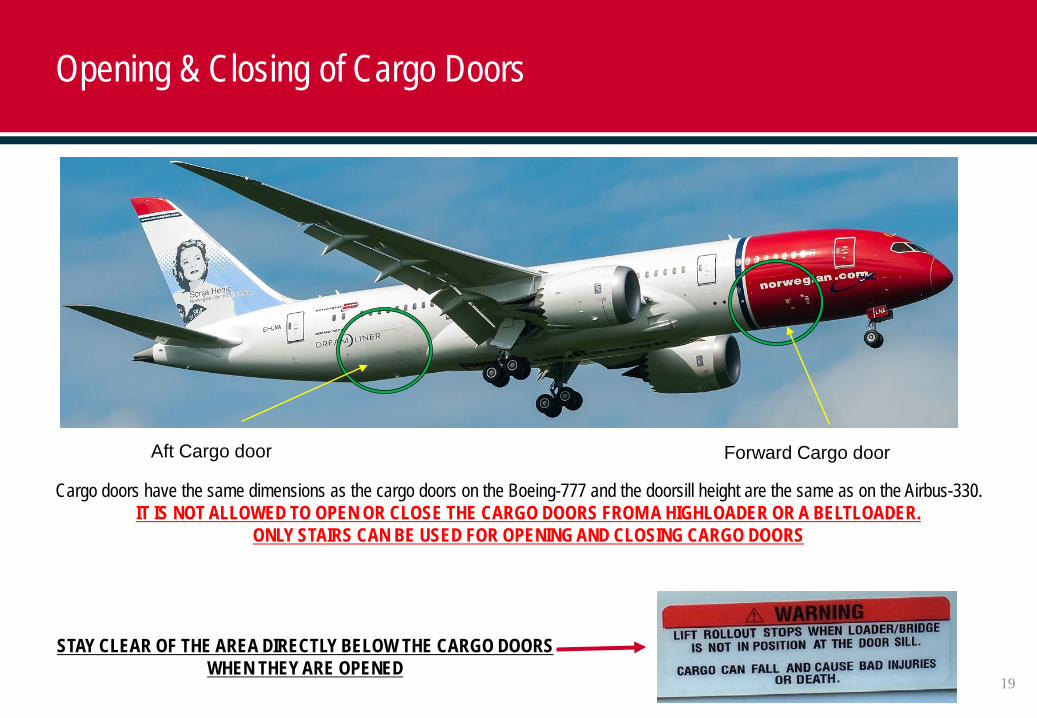
Cargo doors have the same dimensions as the cargo doors on the Boeing-777 and the doorsill height are the same as on the Airbus-330.IT IS NOT ALLOWED TO OPEN OR CLOSE THE CARGO DOORS FROM A HIGHLOADER OR A BELTLOADER.
ONLY STAIRS CAN BE USED FOR OPENING AND CLOSING CARGO DOORS
Aft Cargo door Forward Cargo door
Opening & Closing of Cargo Doors
19
STAY CLEAR OF THE AREA DIRECTLY BELOW THE CARGO DOORS WHEN THEY ARE OPENED
20
Opening & Closing of Cargo Doors
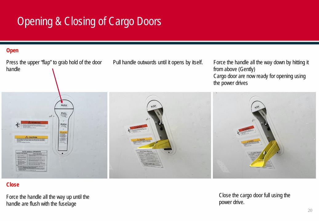
Press the upper “flap” to grab hold of the door handle
Pull handle outwards until it opens by itself. Force the handle all the way down by hitting it from above (Gently)Cargo door are now ready for opening using the power drives
Open
Force the handle all the way up until the handle are flush with the fuselage
Close the cargo door full using the power drive.
Close
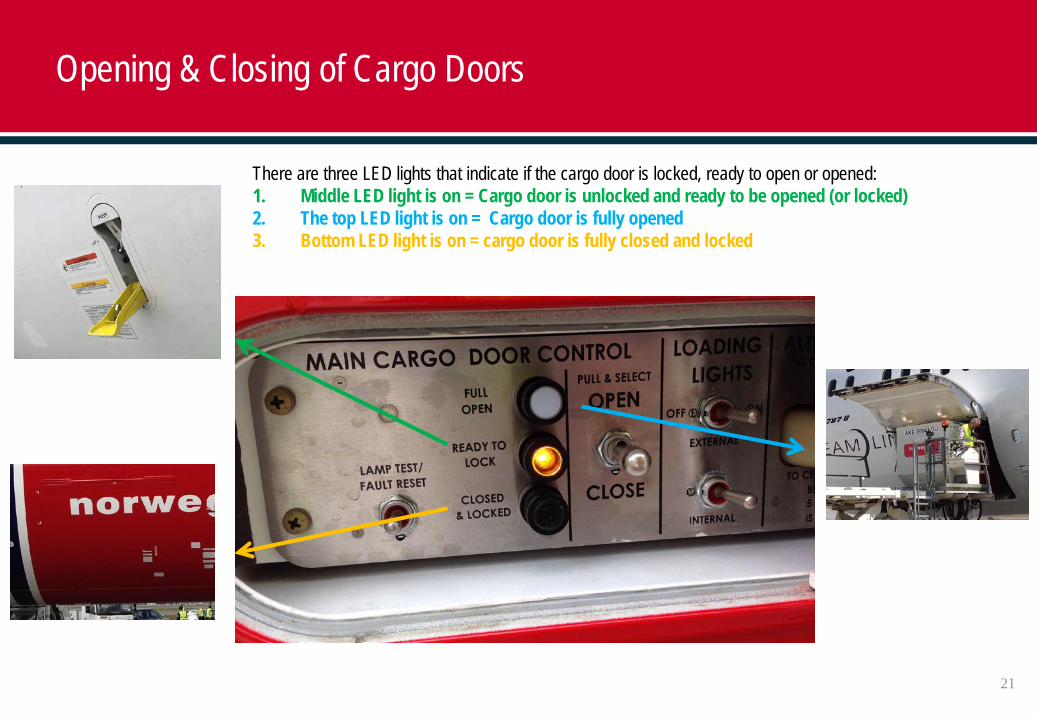
There are three LED lights that indicate if the cargo door is locked, ready to open or opened:1. Middle LED light is on = Cargo door is unlocked and ready to be opened (or locked)2. The top LED light is on = Cargo door is fully opened3. Bottom LED light is on = cargo door is fully closed and locked
21
Opening & Closing of Cargo Doors
22
Opening & Closing of Cargo Doors
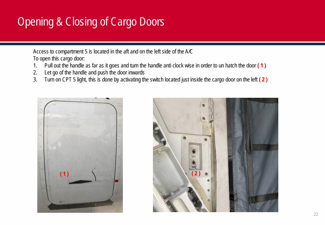
Access to compartment 5 is located in the aft and on the left side of the A/CTo open this cargo door:1. Pull out the handle as far as it goes and turn the handle anti clock wise in order to un hatch the door ( 1 )2. Let go of the handle and push the door inwards3. Turn on CPT 5 light, this is done by activating the switch located just inside the cargo door on the left ( 2 )
( 1 ) ( 2 )
23
Opening & Closing of Cargo Doors
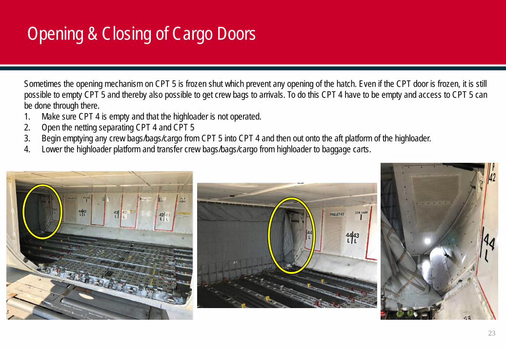
Sometimes the opening mechanism on CPT 5 is frozen shut which prevent any opening of the hatch. Even if the CPT door is frozen, it is still possible to empty CPT 5 and thereby also possible to get crew bags to arrivals. To do this CPT 4 have to be empty and access to CPT 5 can be done through there.1. Make sure CPT 4 is empty and that the highloader is not operated.2. Open the netting separating CPT 4 and CPT 53. Begin emptying any crew bags/bags/cargo from CPT 5 into CPT 4 and then out onto the aft platform of the highloader.4. Lower the highloader platform and transfer crew bags/bags/cargo from highloader to baggage carts.
24
Approaching Cargo Door Opening
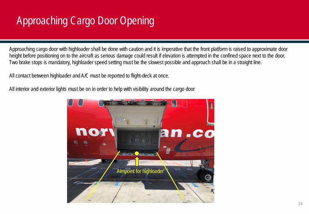
Approaching cargo door with highloader shall be done with caution and it is imperative that the front platform is raised to approximate door height before positioning on to the aircraft as serious damage could result if elevation is attempted in the confined space next to the door. Two brake stops is mandatory, highloader speed setting must be the slowest possible and approach shall be in a straight line.
All contact between highloader and A/C must be reported to flight-deck at once.
All interior and exterior lights must be on in order to help with visibility around the cargo door
Aimpoint for highloader
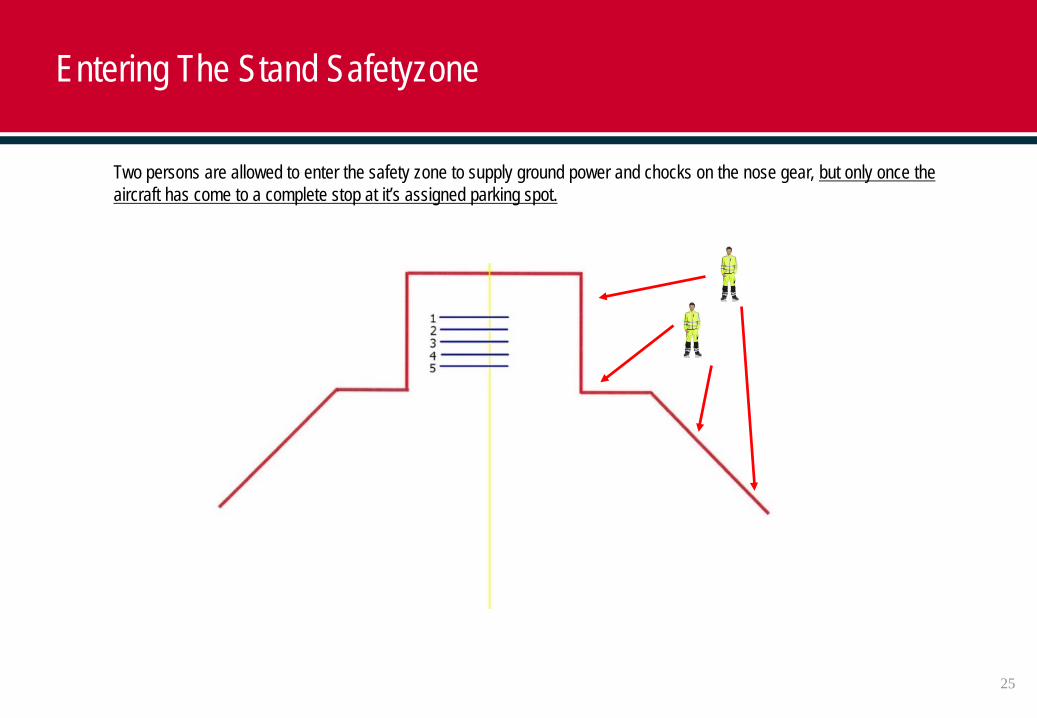
Entering The Stand Safetyzone
Two persons are allowed to enter the safety zone to supply ground power and chocks on the nose gear, but only once the aircraft has come to a complete stop at it’s assigned parking spot.
25
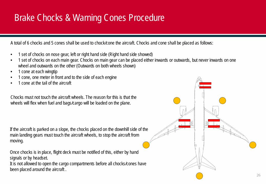
Chocks must not touch the aircraft wheels. The reason for this is that the wheels will flex when fuel and bags/cargo will be loaded on the plane.
Brake Chocks & Warning Cones Procedure
If the aircraft is parked on a slope, the chocks placed on the downhill side of the main landing gears must touch the aircraft wheels, to stop the aircraft from moving.
Once chocks is in place, flight deck must be notified of this, either by hand signals or by headset.It is not allowed to open the cargo compartments before all chocks/cones have been placed around the aircraft .
A total of 6 chocks and 5 cones shall be used to chock/cone the aircraft. Chocks and cone shall be placed as follows:
• 1 set of chocks on nose gear, left or right hand side (Right hand side showed)• 1 set of chocks on each main gear. Chocks on main gear can be placed either inwards or outwards, but never inwards on one
wheel and outwards on the other (Outwards on both wheels shown)• 1 cone at each wingtip• 1 cone, one meter in front and to the side of each engine• 1 cone at the tail of the aircraft
26
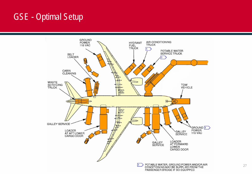
GSE - Optimal Setup
27
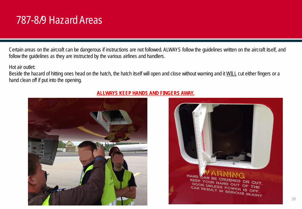
Certain areas on the aircraft can be dangerous if instructions are not followed. ALWAYS follow the guidelines written on the aircraft itself, and follow the guidelines as they are instructed by the various airlines and handlers.
Hot air outlet: Beside the hazard of hitting ones head on the hatch, the hatch itself will open and close without warning and it WILL cut either fingers or a hand clean off if put into the opening.
ALLWAYS KEEP HANDS AND FINGERS AWAY.
787-8/9 Hazard Areas
28
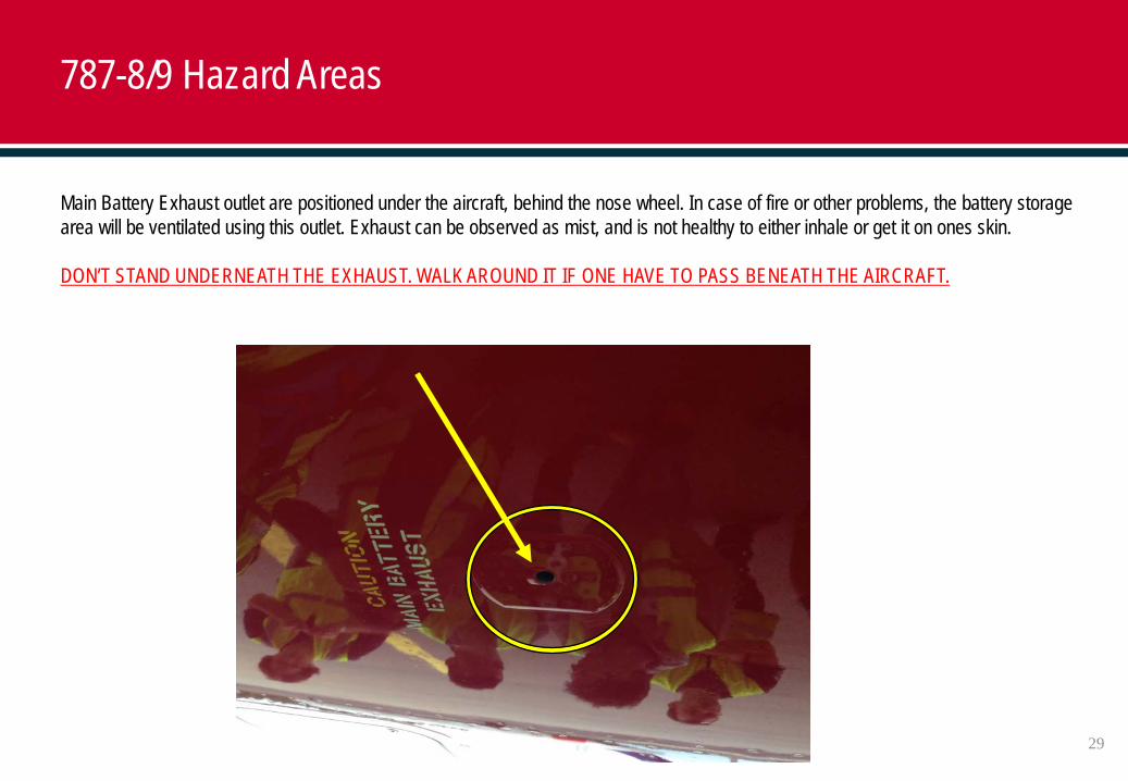
Main Battery Exhaust outlet are positioned under the aircraft, behind the nose wheel. In case of fire or other problems, the battery storage area will be ventilated using this outlet. Exhaust can be observed as mist, and is not healthy to either inhale or get it on ones skin.
DON’T STAND UNDERNEATH THE EXHAUST. WALK AROUND IT IF ONE HAVE TO PASS BENEATH THE AIRCRAFT.
787-8/9 Hazard Areas
29
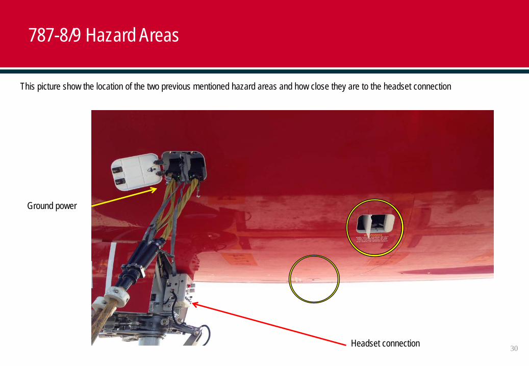
Headset connection
Ground power
This picture show the location of the two previous mentioned hazard areas and how close they are to the headset connection
787-8/9 Hazard Areas
30
787-8/9 Service Hatches
31
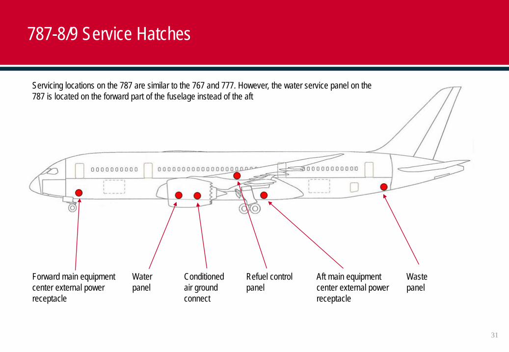
Servicing locations on the 787 are similar to the 767 and 777. However, the water service panel on the 787 is located on the forward part of the fuselage instead of the aft
Forward main equipment center external power receptacle
Water panel
Conditioned air ground connect
Refuel control panel
Aft main equipment center external power receptacle
Waste panel
787-8/9 Service Hatches
32
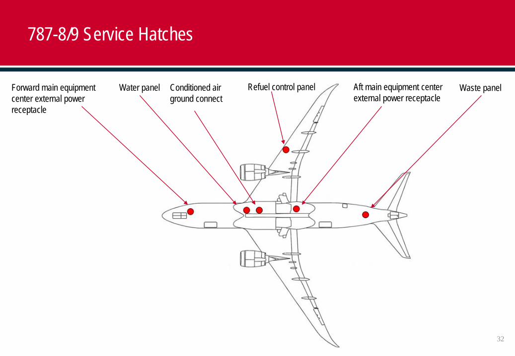
Refuel control panel Forward main equipment center external power receptacle
Conditioned air ground connect
Water panel Waste panelAft main equipment center external power receptacle
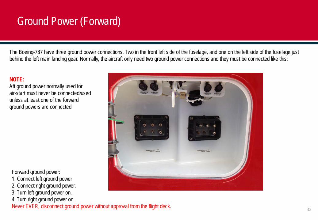
Forward ground power:1: Connect left ground power2: Connect right ground power.3: Turn left ground power on.4: Turn right ground power on.Never EVER, disconnect ground power without approval from the flight deck.
The Boeing-787 have three ground power connections. Two in the front left side of the fuselage, and one on the left side of the fuselage just behind the left main landing gear. Normally, the aircraft only need two ground power connections and they must be connected like this:
NOTE:Aft ground power normally used forair-start must never be connected/usedunless at least one of the forwardground powers are connected
Ground Power (Forward)
33
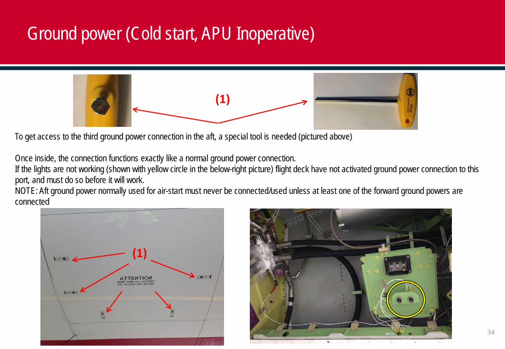
To get access to the third ground power connection in the aft, a special tool is needed (pictured above)
Once inside, the connection functions exactly like a normal ground power connection.If the lights are not working (shown with yellow circle in the below-right picture) flight deck have not activated ground power connection to this port, and must do so before it will work.NOTE: Aft ground power normally used for air-start must never be connected/used unless at least one of the forward ground powers are connected
Ground power (Cold start, APU Inoperative)
(1)
(1)
34
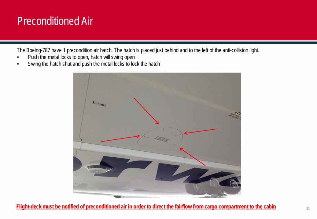
The Boeing-787 have 1 precondition air hatch. The hatch is placed just behind and to the left of the anti-collision light.• Push the metal locks to open, hatch will swing open• Swing the hatch shut and push the metal locks to lock the hatch
Flight-deck must be notified of preconditioned air in order to direct the fairflow from cargo compartment to the cabin
Preconditioned Air
35
Boeing 787-8/9 LIR/LIRF ULD Positions (787-8 shown)
36
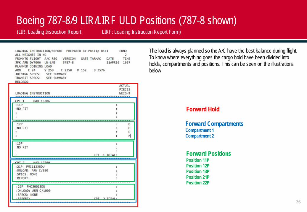
The load is always planned so the A/C have the best balance during flight. To know where everything goes the cargo hold have been divided into holds, compartments and positions. This can be seen on the illustrations below
Forward Hold
Forward CompartmentsCompartment 1Compartment 2
Forward PositionsPosition 11PPosition 12PPosition 13PPosition 21PPosition 22P
(LIR: Loading Instruction Report LIRF: Loading Instruction Report Form)
37
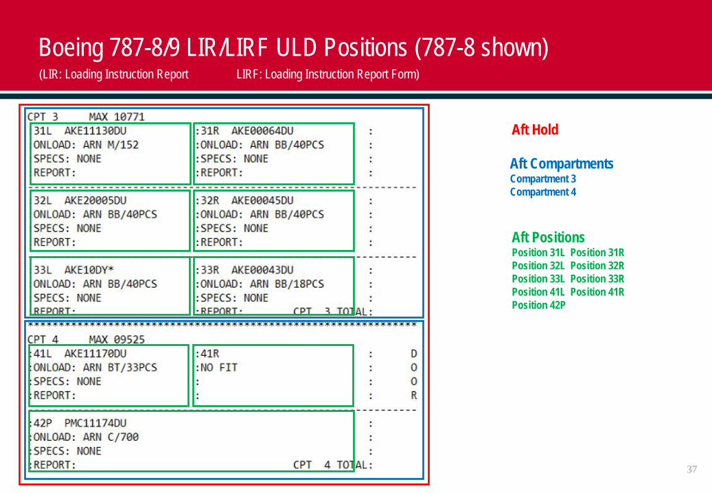
Aft Hold
Aft CompartmentsCompartment 3Compartment 4
Aft PositionsPosition 31L Position 31RPosition 32L Position 32RPosition 33L Position 33RPosition 41L Position 41RPosition 42P
Boeing 787-8/9 LIR/LIRF ULD Positions (787-8 shown)(LIR: Loading Instruction Report LIRF: Loading Instruction Report Form)
38
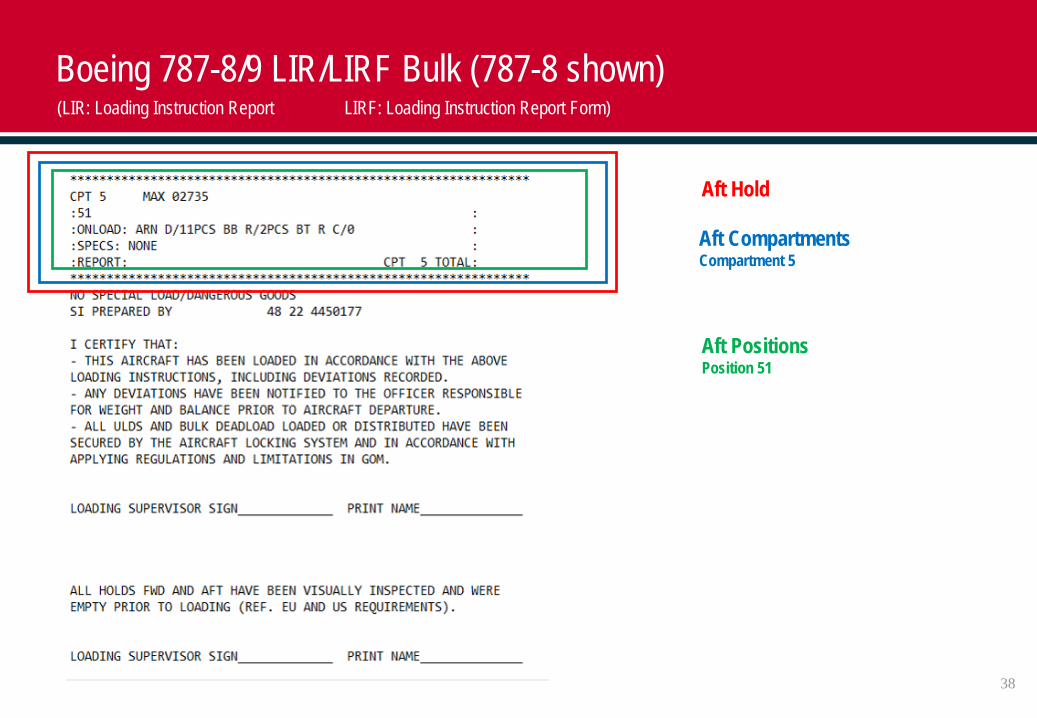
Aft Hold
Aft CompartmentsCompartment 5
Aft PositionsPosition 51
Boeing 787-8/9 LIR/LIRF Bulk (787-8 shown)(LIR: Loading Instruction Report LIRF: Loading Instruction Report Form)
39
Boeing 787-8/9 LIR/LIRF ULD Positions (787-8 shown)
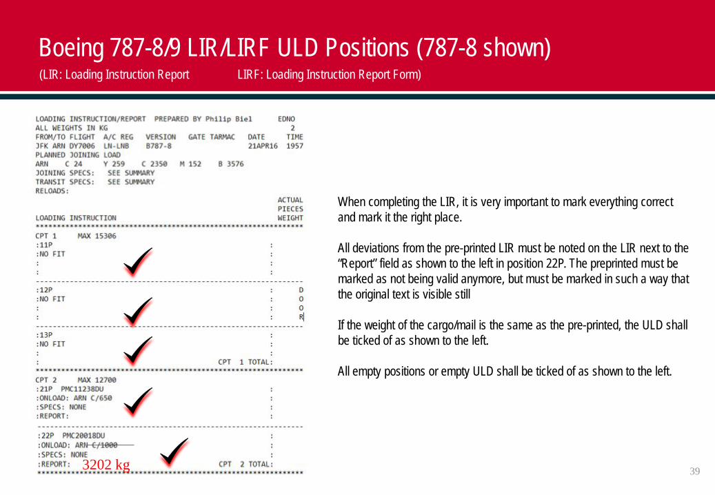
When completing the LIR, it is very important to mark everything correct and mark it the right place.
All deviations from the pre-printed LIR must be noted on the LIR next to the “Report” field as shown to the left in position 22P. The preprinted must be marked as not being valid anymore, but must be marked in such a way that the original text is visible still
If the weight of the cargo/mail is the same as the pre-printed, the ULD shall be ticked of as shown to the left.
All empty positions or empty ULD shall be ticked of as shown to the left.
3202 kg
(LIR: Loading Instruction Report LIRF: Loading Instruction Report Form)
40
Boeing 787-8/9 LIR/LIRF ULD Positions (787-8 shown)(LIR: Loading Instruction Report LIRF: Loading Instruction Report Form)
202 kg
20 pcs
X
34 pcs41 pcs
34 pcs
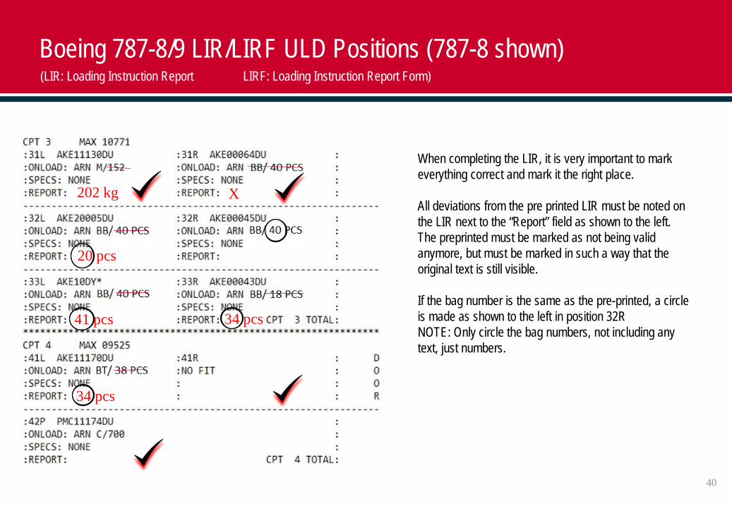
When completing the LIR, it is very important to mark everything correct and mark it the right place.
All deviations from the pre printed LIR must be noted on the LIR next to the “Report” field as shown to the left. The preprinted must be marked as not being valid anymore, but must be marked in such a way that the original text is still visible.
If the bag number is the same as the pre-printed, a circle is made as shown to the left in position 32RNOTE: Only circle the bag numbers, not including any text, just numbers.
41
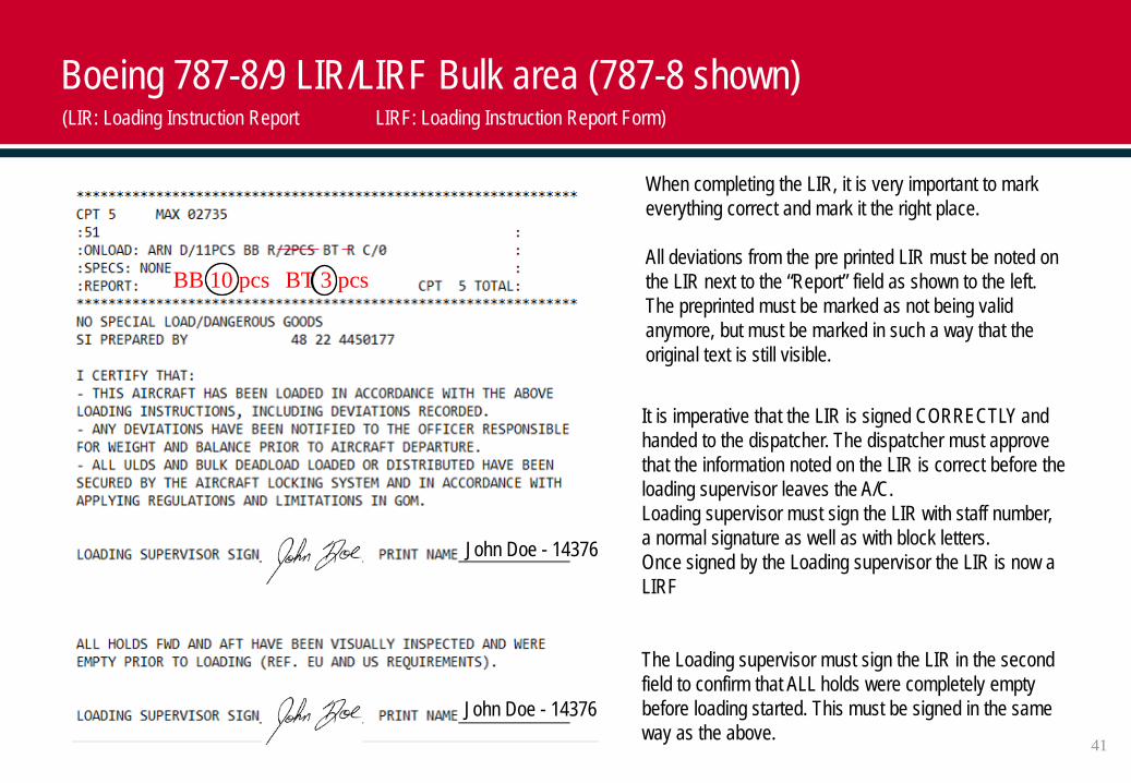
BB 10 pcs BT 3 pcs
Boeing 787-8/9 LIR/LIRF Bulk area (787-8 shown)
When completing the LIR, it is very important to mark everything correct and mark it the right place.
All deviations from the pre printed LIR must be noted on the LIR next to the “Report” field as shown to the left. The preprinted must be marked as not being valid anymore, but must be marked in such a way that the original text is still visible.
It is imperative that the LIR is signed CORRECTLY and handed to the dispatcher. The dispatcher must approve that the information noted on the LIR is correct before the loading supervisor leaves the A/C.Loading supervisor must sign the LIR with staff number, a normal signature as well as with block letters.Once signed by the Loading supervisor the LIR is now a LIRF
The Loading supervisor must sign the LIR in the second field to confirm that ALL holds were completely empty before loading started. This must be signed in the same way as the above.
(LIR: Loading Instruction Report LIRF: Loading Instruction Report Form)
John Doe - 14376
John Doe - 14376
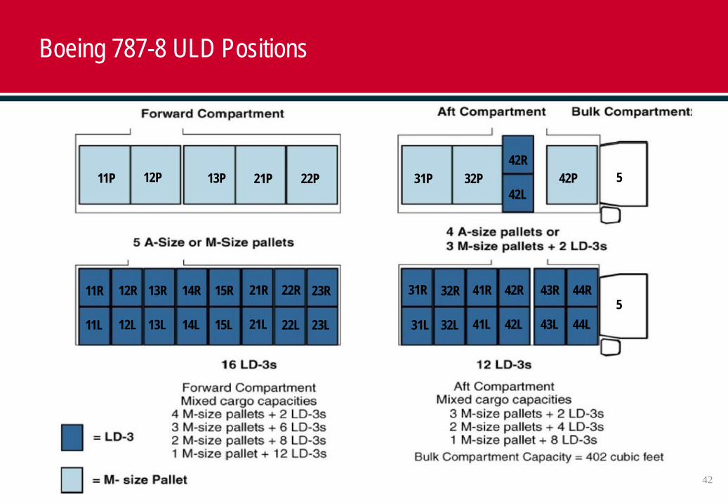
Boeing 787-8 ULD Positions
42
22P21P13P12P11P 31P 32P 42P
23R22R21R15R14R13R12R11R
23L22L21L15L14L13L12L11L
5
44R43R42R41R32R31R
44L43L42L41L32L31L
42R
42L
5
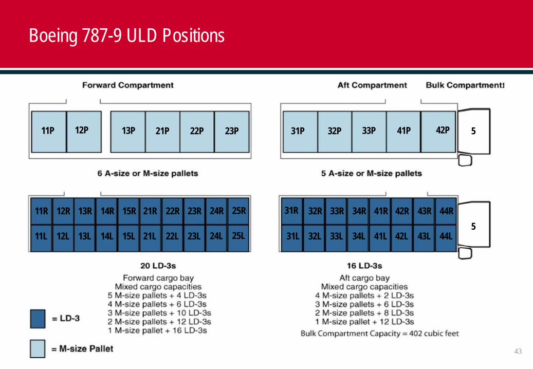
Boeing 787-9 ULD Positions
43
22P 23P21P13P12P11P 31P 32P 33P 41P 42P
25R24R23R22R21R15R14R13R12R11R
25L24L23L22L21L15L14L13L12L11L5
44R43R42R41R34R33R32R31R
44L43L42L41L34L33L32L31L
5
44
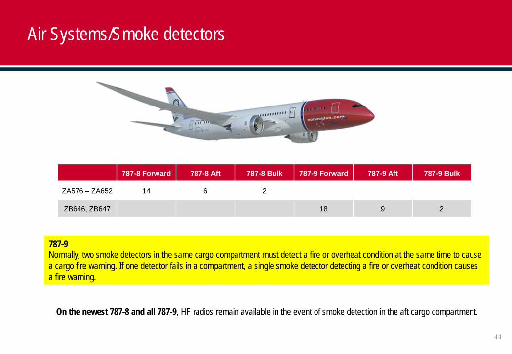
Air Systems/Smoke detectors
787-8 Forward 787-8 Aft 787-8 Bulk 787-9 Forward 787-9 Aft 787-9 Bulk
ZA576 – ZA652 14 6 2
ZB646, ZB647 18 9 2
787-9Normally, two smoke detectors in the same cargo compartment must detect a fire or overheat condition at the same time to cause a cargo fire warning. If one detector fails in a compartment, a single smoke detector detecting a fire or overheat condition causes a fire warning.
On the newest 787-8 and all 787-9, HF radios remain available in the event of smoke detection in the aft cargo compartment.
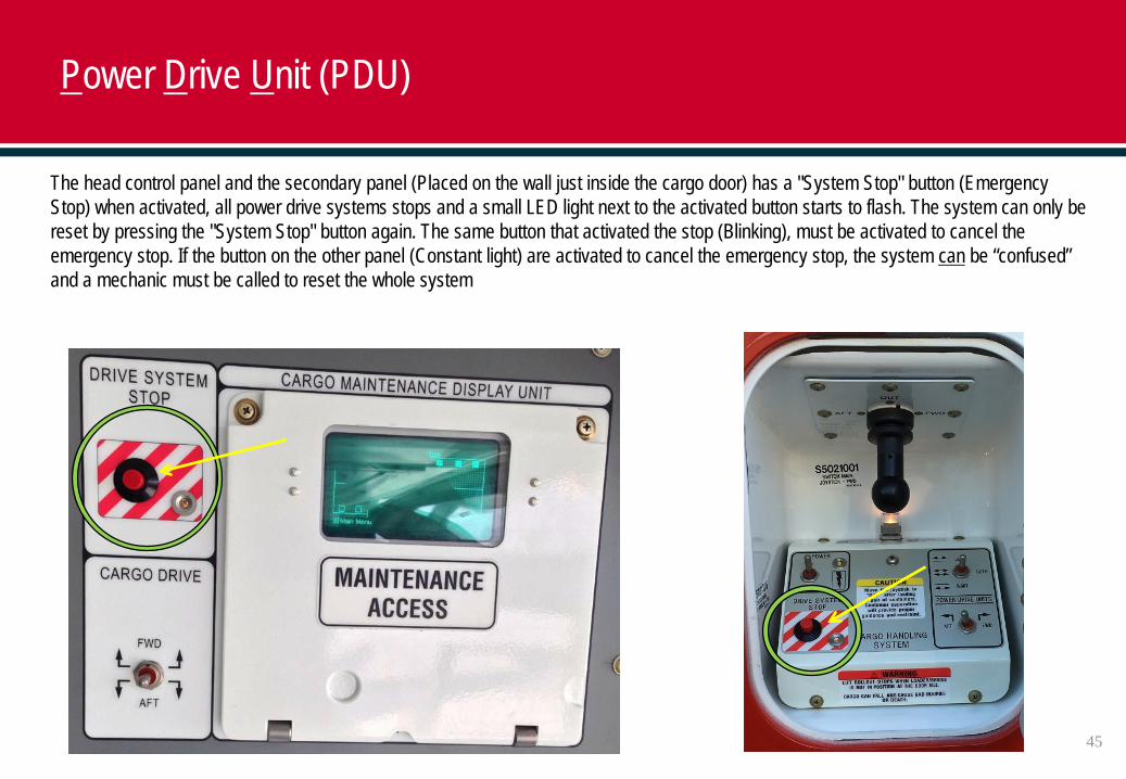
The head control panel and the secondary panel (Placed on the wall just inside the cargo door) has a "System Stop" button (Emergency Stop) when activated, all power drive systems stops and a small LED light next to the activated button starts to flash. The system can only be reset by pressing the "System Stop" button again. The same button that activated the stop (Blinking), must be activated to cancel the emergency stop. If the button on the other panel (Constant light) are activated to cancel the emergency stop, the system can be “confused” and a mechanic must be called to reset the whole system
Power Drive Unit (PDU)
45
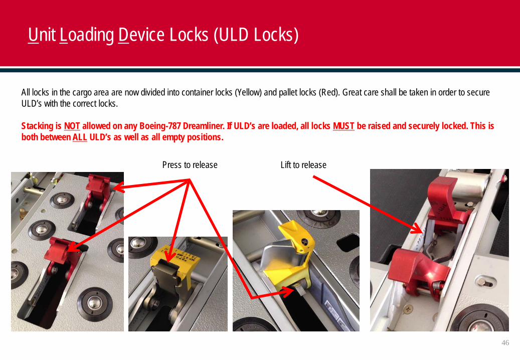
All locks in the cargo area are now divided into container locks (Yellow) and pallet locks (Red). Great care shall be taken in order to secure ULD’s with the correct locks.
Stacking is NOT allowed on any Boeing-787 Dreamliner. If ULD’s are loaded, all locks MUST be raised and securely locked. This is both between ALL ULD’s as well as all empty positions.
Press to release Lift to release
Unit Loading Device Locks (ULD Locks)
46
47
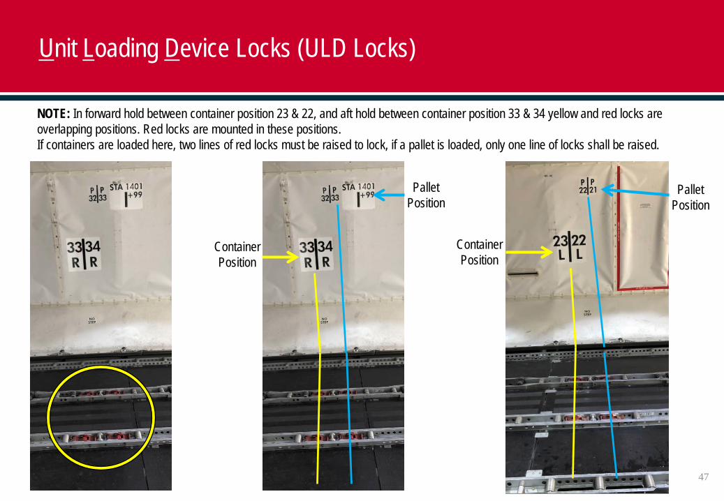
Unit Loading Device Locks (ULD Locks)
NOTE: In forward hold between container position 23 & 22, and aft hold between container position 33 & 34 yellow and red locks are overlapping positions. Red locks are mounted in these positions.If containers are loaded here, two lines of red locks must be raised to lock, if a pallet is loaded, only one line of locks shall be raised.
ContainerPosition
ContainerPosition
PalletPosition
PalletPosition
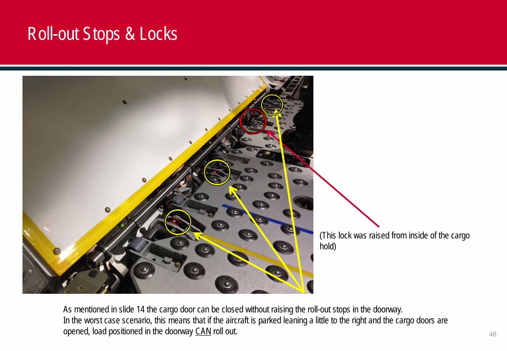
As mentioned in slide 14 the cargo door can be closed without raising the roll-out stops in the doorway.In the worst case scenario, this means that if the aircraft is parked leaning a little to the right and the cargo doors are opened, load positioned in the doorway CAN roll out.
(This lock was raised from inside of the cargo hold)
Roll-out Stops & Locks
48
49
Loading ULD’s
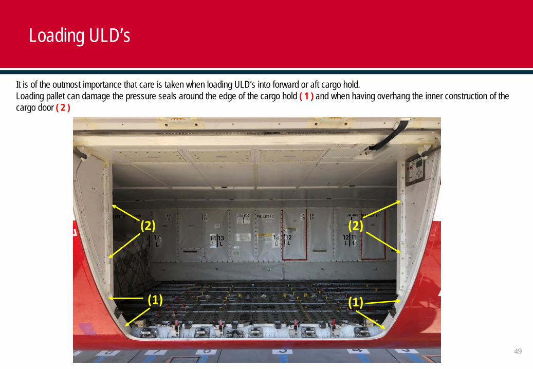
It is of the outmost importance that care is taken when loading ULD’s into forward or aft cargo hold.Loading pallet can damage the pressure seals around the edge of the cargo hold ( 1 ) and when having overhang the inner construction of the cargo door ( 2 )
(1) (1)
(2) (2)
50
Loading ULD’s
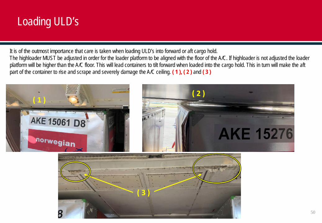
It is of the outmost importance that care is taken when loading ULD’s into forward or aft cargo hold.The highloader MUST be adjusted in order for the loader platform to be aligned with the floor of the A/C. If highloader is not adjusted the loader platform will be higher than the A/C floor. This will lead containers to tilt forward when loaded into the cargo hold. This in turn will make the aft part of the container to rise and scrape and severely damage the A/C ceiling. ( 1 ), ( 2 ) and ( 3 )
( 1 )( 2 )
( 3 )
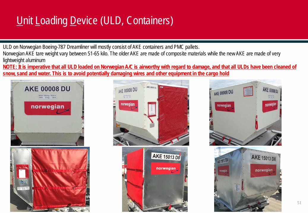
ULD on Norwegian Boeing-787 Dreamliner will mostly consist of AKE containers and PMC pallets. Norwegian AKE tare weight vary between 51-65 kilo. The older AKE are made of composite materials while the new AKE are made of very lightweight aluminumNOTE: It is imperative that all ULD loaded on Norwegian A/C is airworthy with regard to damage, and that all ULDs have been cleaned of snow, sand and water. This is to avoid potentially damaging wires and other equipment in the cargo hold
Unit Loading Device (ULD, Containers)
51
52
Unit Loading Device (ULD, Containers)
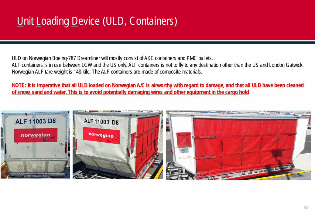
ULD on Norwegian Boeing-787 Dreamliner will mostly consist of AKE containers and PMC pallets. ALF containers is in use between LGW and the US only. ALF containers is not to fly to any destination other than the US and London Gatwick.Norwegian ALF tare weight is 148 kilo. The ALF containers are made of composite materials.
NOTE: It is imperative that all ULD loaded on Norwegian A/C is airworthy with regard to damage, and that all ULD have been cleaned of snow, sand and water. This is to avoid potentially damaging wires and other equipment in the cargo hold
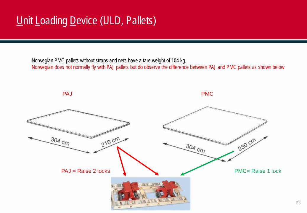
Norwegian PMC pallets without straps and nets have a tare weight of 104 kg.Norwegian does not normally fly with PAJ pallets but do observe the difference between PAJ and PMC pallets as shown below
Unit Loading Device (ULD, Pallets)
PMCPAJ
PAJ = Raise 2 locks PMC= Raise 1 lock
53
54
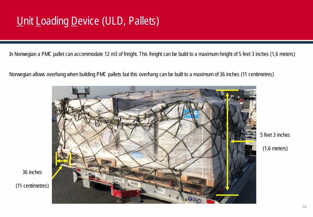
Unit Loading Device (ULD, Pallets)
In Norwegian a PMC pallet can accommodate 12 m3 of freight. This freight can be build to a maximum height of 5 feet 3 inches (1,6 meters)
Norwegian allows overhang when building PMC pallets but this overhang can be built to a maximum of 36 inches (11 centimetres)
5 feet 3 inches
(1,6 meters)
36 inches
(11 centimetres)
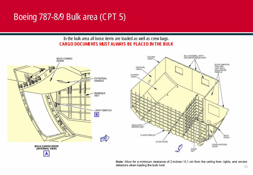
Boeing 787-8/9 Bulk area (CPT 5)
In the bulk area all loose items are loaded as well as crew bags. CARGO DOCUMENTS MUST ALWAYS BE PLACED IN THE BULK
55
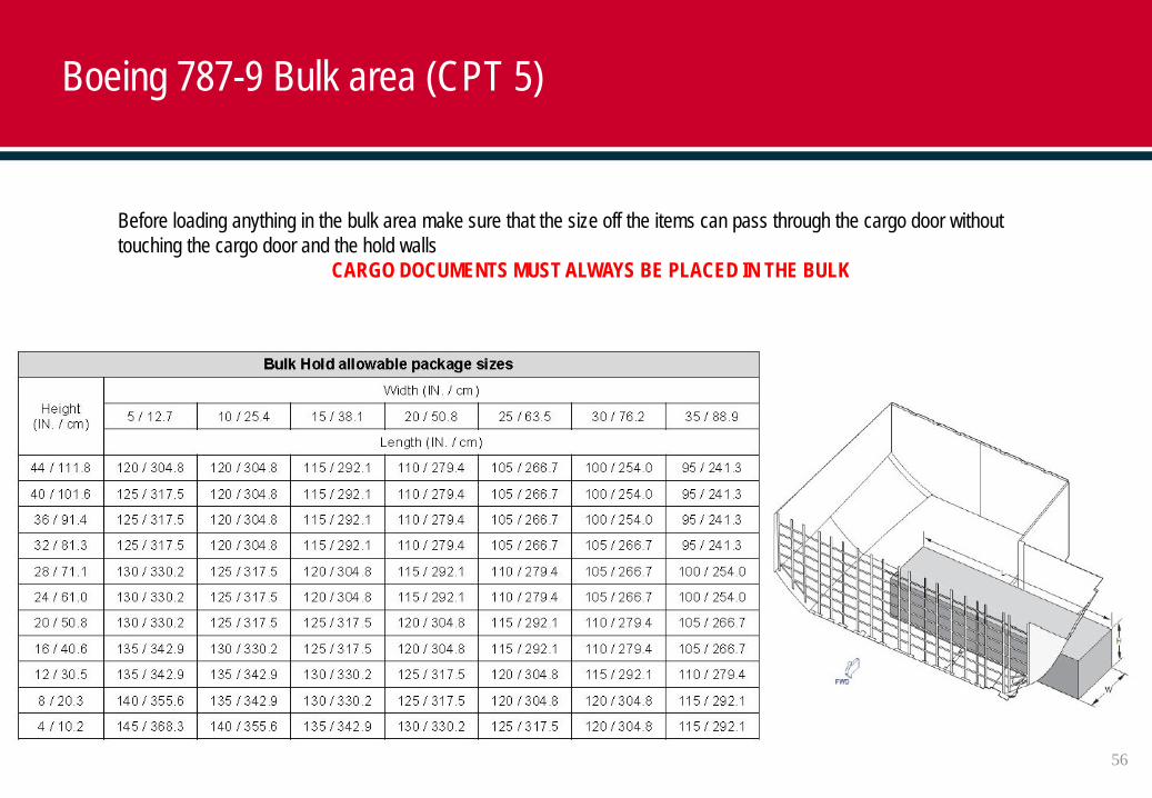
Boeing 787-9 Bulk area (CPT 5)
Before loading anything in the bulk area make sure that the size off the items can pass through the cargo door without touching the cargo door and the hold walls
CARGO DOCUMENTS MUST ALWAYS BE PLACED IN THE BULK
56
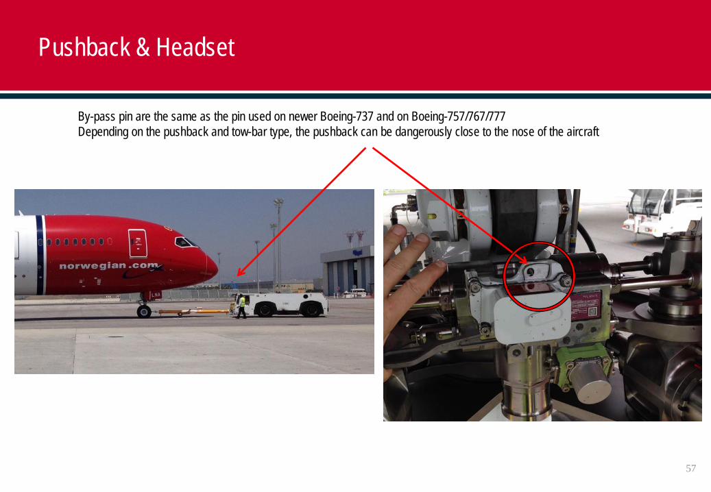
By-pass pin are the same as the pin used on newer Boeing-737 and on Boeing-757/767/777Depending on the pushback and tow-bar type, the pushback can be dangerously close to the nose of the aircraft
Pushback & Headset
57
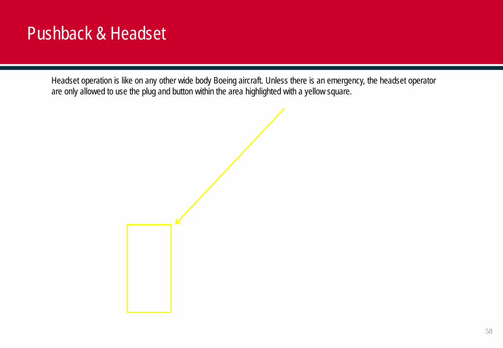
Headset operation is like on any other wide body Boeing aircraft. Unless there is an emergency, the headset operator are only allowed to use the plug and button within the area highlighted with a yellow square.
Pushback & Headset
58
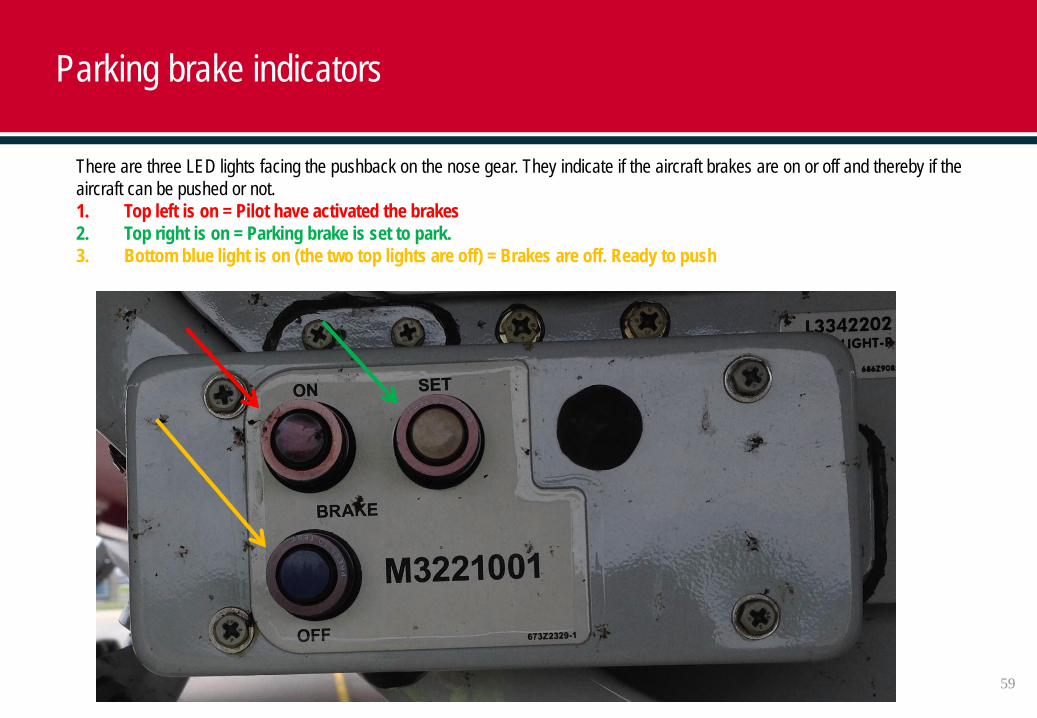
There are three LED lights facing the pushback on the nose gear. They indicate if the aircraft brakes are on or off and thereby if the aircraft can be pushed or not.1. Top left is on = Pilot have activated the brakes2. Top right is on = Parking brake is set to park.3. Bottom blue light is on (the two top lights are off) = Brakes are off. Ready to push
Parking brake indicators
59
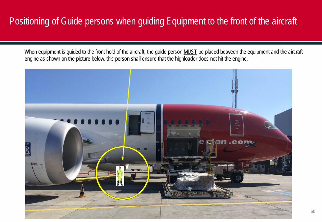
When equipment is guided to the front hold of the aircraft, the guide person MUST be placed between the equipment and the aircraft engine as shown on the picture below, this person shall ensure that the highloader does not hit the engine.
Positioning of Guide persons when guiding Equipment to the front of the aircraft
60
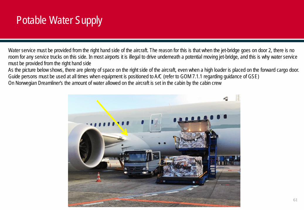
Water service must be provided from the right hand side of the aircraft. The reason for this is that when the jet-bridge goes on door 2, there is no room for any service trucks on this side. In most airports it is illegal to drive underneath a potential moving jet-bridge, and this is why water service must be provided from the right hand sideAs the picture below shows, there are plenty of space on the right side of the aircraft, even when a high loader is placed on the forward cargo door. Guide persons must be used at all times when equipment is positioned to A/C (refer to GOM 7.1.1 regarding guidance of GSE)On Norwegian Dreamliner's the amount of water allowed on the aircraft is set in the cabin by the cabin crew
Potable Water Supply
61
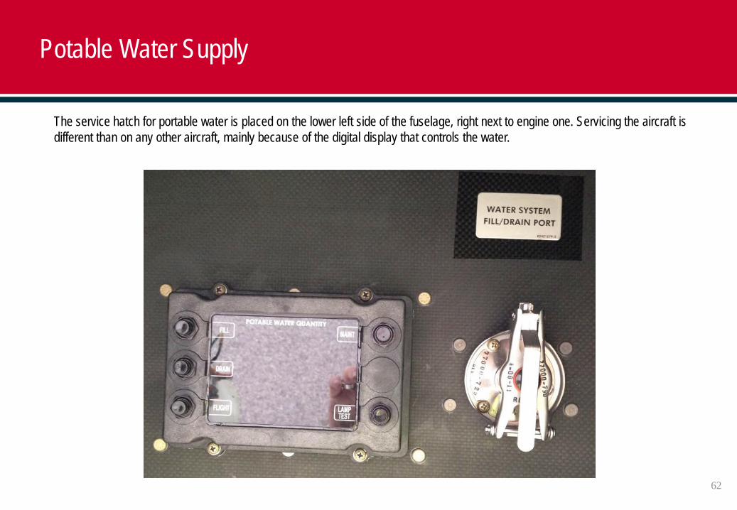
The service hatch for portable water is placed on the lower left side of the fuselage, right next to engine one. Servicing the aircraft is different than on any other aircraft, mainly because of the digital display that controls the water.
Potable Water Supply
62
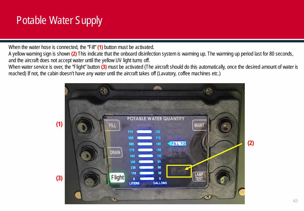
When the water hose is connected, the ”Fill” (1) button must be activated. A yellow warning sign is shown (2) This indicate that the onboard disinfection system is warming up. The warming up period last for 80 seconds, and the aircraft does not accept water until the yellow UV light turns off. When water service is over, the ”Flight” button (3) must be activated (The aircraft should do this automatically, once the desired amount of water is reached) If not, the cabin doesn’t have any water until the aircraft takes off (Lavatory, coffee machines etc.)
(1)
(3)
(2)
63
Potable Water Supply
Flight
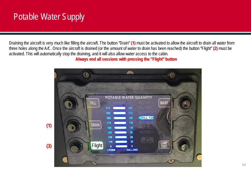
Draining the aircraft is very much like filling the aircraft. The button ”Drain” (1) must be activated to allow the aircraft to drain all water from three holes along the A/C. Once the aircraft is drained (or the amount of water to drain has been reached) the button ”Flight” (2) must be activated. This will automatically stop the draining, and it will also allow water access to the cabin.
Always end all sessions with pressing the ”Flight” button
64
Potable Water Supply
(1)
(3) Flight
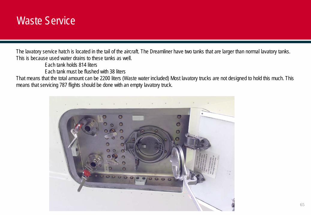
The lavatory service hatch is located in the tail of the aircraft. The Dreamliner have two tanks that are larger than normal lavatory tanks. This is because used water drains to these tanks as well.
Each tank holds 814 litersEach tank must be flushed with 38 liters
That means that the total amount can be 2200 liters (Waste water included) Most lavatory trucks are not designed to hold this much. This means that servicing 787 flights should be done with an empty lavatory truck.
65
Waste Service
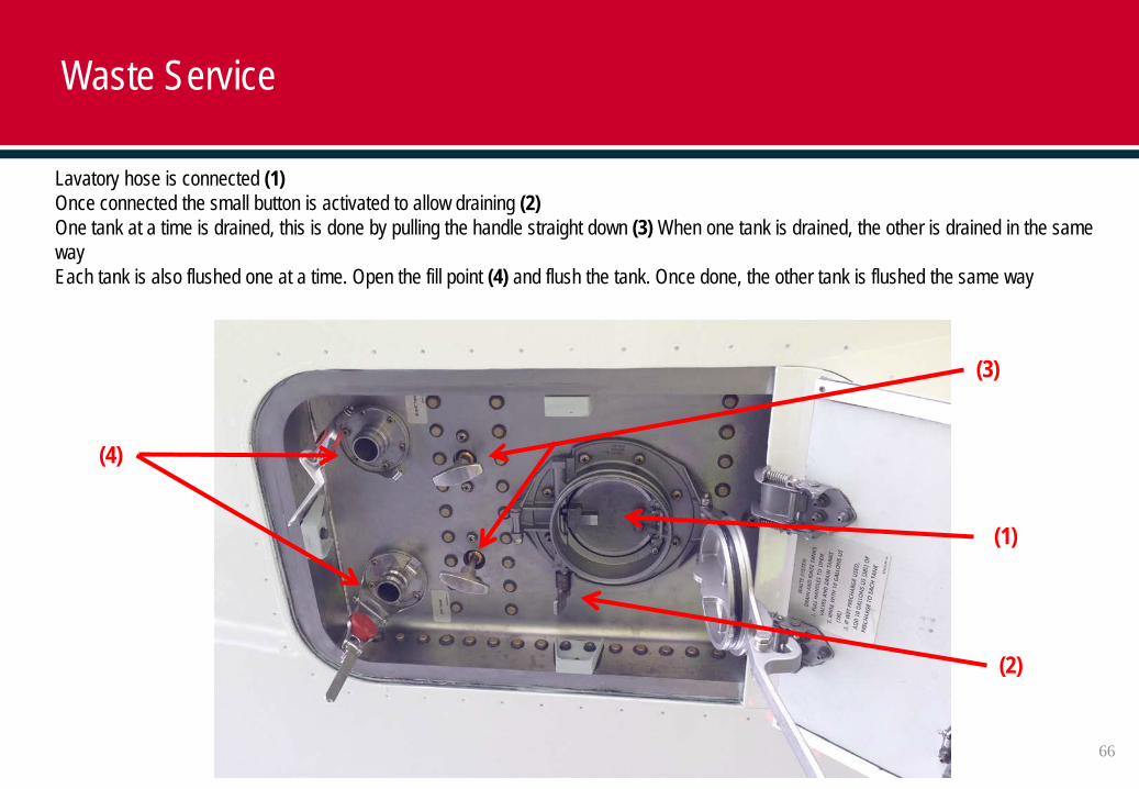
Lavatory hose is connected (1)Once connected the small button is activated to allow draining (2)One tank at a time is drained, this is done by pulling the handle straight down (3) When one tank is drained, the other is drained in the same wayEach tank is also flushed one at a time. Open the fill point (4) and flush the tank. Once done, the other tank is flushed the same way
(1)
(2)
(3)
(4)
66
Waste Service
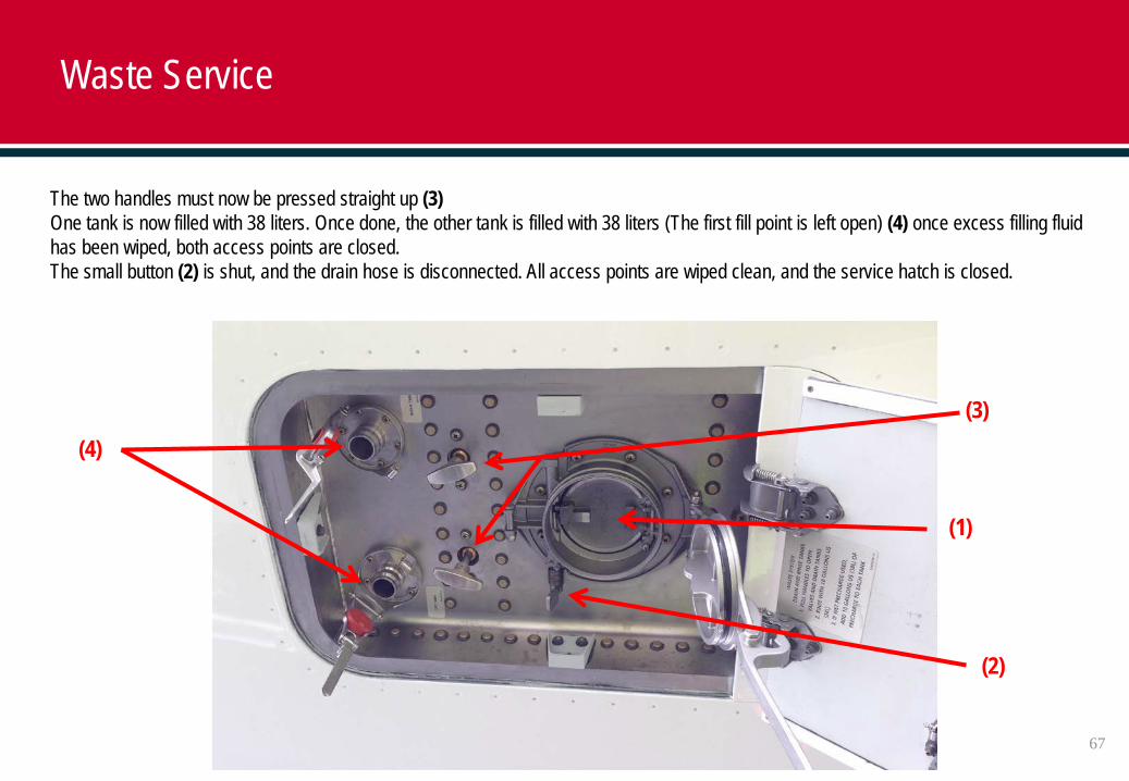
The two handles must now be pressed straight up (3)One tank is now filled with 38 liters. Once done, the other tank is filled with 38 liters (The first fill point is left open) (4) once excess filling fluid has been wiped, both access points are closed.The small button (2) is shut, and the drain hose is disconnected. All access points are wiped clean, and the service hatch is closed.
(3)(4)
(2)
(1)
67
Waste Service
68
End
Recommended