NORDSTROM VALVES®
IRON PLUG VALVES
Nordstrom Valves
AN ISO 9001 REGISTERED COMPANY
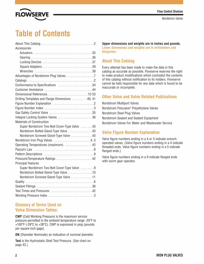
About This Catalog . . . . . . . . . . . . . . . . . . . . . . . . . . . . . . . .2Accessories
Actuators . . . . . . . . . . . . . . . . . . . . . . . . . . . . . . . . . . .35Gearing . . . . . . . . . . . . . . . . . . . . . . . . . . . . . . . . . . . . .36Locking Devices . . . . . . . . . . . . . . . . . . . . . . . . . . . . . .37Square Adapters . . . . . . . . . . . . . . . . . . . . . . . . . . . . . .39Wrenches . . . . . . . . . . . . . . . . . . . . . . . . . . . . . . . . . . .38
Advantages of Nordstrom Plug Valves . . . . . . . . . . . . . . . . .7Catalogs . . . . . . . . . . . . . . . . . . . . . . . . . . . . . . . . . . . . . . . .2Conformance to Specifications . . . . . . . . . . . . . . . . . . . . .34Customer Assistance . . . . . . . . . . . . . . . . . . . . . . . . . . . . .44Dimensional References . . . . . . . . . . . . . . . . . . . . . . . .12-33Drilling Templates and Flange Dimensions . . . . . . . . .40, 41Figure Number Explanation . . . . . . . . . . . . . . . . . . . . . . . . .2Figure Number Index . . . . . . . . . . . . . . . . . . . . . . . . . . . . . .3Gas Safety Control Valve . . . . . . . . . . . . . . . . . . . . . . . . . .35Integral Locking System Valves . . . . . . . . . . . . . . . . . . . . 36Materials of Construction
Super Nordstrom Two-Bolt Cover-Type Valve . . . . . . .43Nordstrom Bolted Gland-Type Valve . . . . . . . . . . . . . . .43Nordstrom Screwed Gland-Type Valve . . . . . . . . . . . . .43
Nordstrom Iron Plug Valves . . . . . . . . . . . . . . . . . . . . . .4, 5Operating Temperatures (maximum) . . . . . . . . . . . . . . . . 42Pascal’s Law . . . . . . . . . . . . . . . . . . . . . . . . . . . . . . . . . . . .8Pattern Descriptions . . . . . . . . . . . . . . . . . . . . . . . . . . . . . .8Pressure/Temperature Ratings . . . . . . . . . . . . . . . . . . . . . .42Principal Features
Super Nordstrom Two-Bolt Cover-Type Valve . . . . . . . .9Nordstrom Bolted Gland-Type Valve . . . . . . . . . . . . . . .10Nordstrom Screwed Gland-Type Valve . . . . . . . . . . . . .11
Quality . . . . . . . . . . . . . . . . . . . . . . . . . . . . . . . . . . . . . . . . .6Sealant Fittings . . . . . . . . . . . . . . . . . . . . . . . . . . . . . . . . . 36Test Times and Pressures . . . . . . . . . . . . . . . . . . . . . . . . .42Working Pressure Index . . . . . . . . . . . . . . . . . . . . . . . . . . . .3
Glossary of Terms Used onValve Dimension Tables:CWP (Cold Working Pressure) is the maximum servicepressure permitted in the ambient temperature range -20°F to+100°F (-29°C to +38°C). CWP is expressed in psig (poundsper square inch gage).
DN (Diameter Nominale) an indication of nominal diameter.
Test is the Hydrostatic Shell Test Pressure. (See chart onpage 42.)
Upper dimensions and weights are in inches and pounds.Lower dimensions and weights are in millimeters andkilograms.
About This CatalogEvery attempt has been made to make the data in thiscatalog as accurate as possible. Flowserve reserves the rightto make product modifications which contradict the contentsof this catalog without notification to its holders. Flowservecannot be held responsible for any data which is found to beinaccurate or incomplete.
Other Valve and Valve Related PublicationsNordstrom Multiport ValvesNordstrom Polyvalve® Polyethylene ValvesNordstrom Steel Plug ValvesNordstrom Sealant and Sealant EquipmentNordstrom Valves For Water and Wastewater Service
Valve Figure Number ExplanationValve figure numbers ending in a 4 or 5 indicate wrench-operated valves. (Valve figure numbers ending in a 4 indicatethreaded ends. Valve figure numbers ending in a 5 indicateflanged ends.)
Valve figure numbers ending in a 9 indicate flanged endswith worm gear operator.
Flow Control Division
Nordstrom Valves
2 IRON PLUG VALVES
Table of Contents
Flow Control Division
Nordstrom Valves
IRON PLUG VALVES 3
Figure Number . . . .Page
114 . . . . . . . . . . . . . . . .15
115 . . . . . . . . . . . . . . . .15
142 . . . . . . . . . . . . . . . .12
143 . . . . . . . . . . . . .12, 13
149 . . . . . . . . . . . . . . . .14
164 . . . . . . . . . . . . . . . .20
165 . . . . . . . . . . . . . . . .20
Figure Number . . . .Page
169 . . . . . . . . . . . . . . . .21
185 . . . . . . . . . . . . . . . .18
189 . . . . . . . . . . . . . . . .18
214 . . . . . . . . . . . . . . . .19
265 . . . . . . . . . . . . . . . .26
269 . . . . . . . . . . . . . . . .27
305 . . . . . . . . . . . . . . . .22
Figure Number . . . .Page
524 . . . . . . . . . . . . . . . .23
525 . . . . . . . . . . . . . . . .23
824 . . . . . . . . . . . . . . . .30
825 . . . . . . . . . . . . . . . .30
1169 . . . . . . . . . . . .16, 17
1485 . . . . . . . . . . . . . . .24
1489 . . . . . . . . . . . .24, 25
Figure Number . . . .Page
1585 . . . . . . . . . . . . . . .28
1589 . . . . . . . . . . . .28, 29
2815 . . . . . . . . . . . . . . .31
2865 . . . . . . . . . . . . . . .31
23144 . . . . . . . . . . . . . .33
24191 . . . . . . . . . . . . . .32
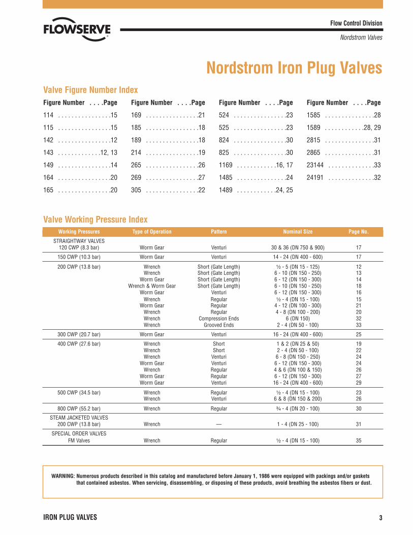
Nordstrom Iron Plug ValvesValve Figure Number Index
Valve Working Pressure IndexWorking Pressures Type of Operation Pattern Nominal Size Page No.
STRAIGHTWAY VALVES120 CWP (8.3 bar) Worm Gear Venturi 30 & 36 (DN 750 & 900) 17
150 CWP (10.3 bar) Worm Gear Venturi 14 - 24 (DN 400 - 600) 17
200 CWP (13.8 bar) Wrench Short (Gate Length) ¹�₂ - 5 (DN 15 - 125) 12Wrench Short (Gate Length) 6 - 10 (DN 150 - 250) 13
Worm Gear Short (Gate Length) 6 - 12 (DN 150 - 300) 14Wrench & Worm Gear Short (Gate Length) 6 - 10 (DN 150 - 250) 18
Worm Gear Venturi 6 - 12 (DN 150 - 300) 16Wrench Regular ¹�₂ - 4 (DN 15 - 100) 15
Worm Gear Regular 4 - 12 (DN 100 - 300) 21Wrench Regular 4 - 8 (DN 100 - 200) 20Wrench Compression Ends 6 (DN 150) 32Wrench Grooved Ends 2 - 4 (DN 50 - 100) 33
300 CWP (20.7 bar) Worm Gear Venturi 16 - 24 (DN 400 - 600) 25
400 CWP (27.6 bar) Wrench Short 1 & 2 (DN 25 & 50) 19Wrench Short 2 - 4 (DN 50 - 100) 22Wrench Venturi 6 - 8 (DN 150 - 250) 24
Worm Gear Venturi 6 - 12 (DN 150 - 300) 24Wrench Regular 4 & 6 (DN 100 & 150) 26
Worm Gear Regular 6 - 12 (DN 150 - 300) 27Worm Gear Venturi 16 - 24 (DN 400 - 600) 29
500 CWP (34.5 bar) Wrench Regular ¹�₂ - 4 (DN 15 - 100) 23Wrench Venturi 6 & 8 (DN 150 & 200) 26
800 CWP (55.2 bar) Wrench Regular ³�₄ - 4 (DN 20 - 100) 30
STEAM JACKETED VALVES200 CWP (13.8 bar) Wrench — 1 - 4 (DN 25 - 100) 31
SPECIAL ORDER VALVESFM Valves Wrench Regular ¹�₂ - 4 (DN 15 - 100) 35
WARNING: Numerous products described in this catalog and manufactured before January 1, 1986 were equipped with packings and/or gasketsthat contained asbestos. When servicing, disassembling, or disposing of these products, avoid breathing the asbestos fibers or dust.
Over the past 70 years, an estimated 70,000,000 Nordstromvalves have been installed in just about every type ofcommercial service imaginable. Many of these valves — stillin service today — are considerably older than the personscurrently operating them.
This widespread acceptance and long-time usage is a tributeto the versatility, proven performance and rugged durabilityof the Nordstrom valve design. It also demonstrates theeffectiveness of the many improvements that have resultedfrom Nordstrom’s continuing advances in valve design,materials application engineering and production technologywhich have upgraded valve performance while maintainingcompetitive pricing. Obviously, a great many users agreethat the Nordstrom iron plug valve is one of the best valueson the market today!
A Technology LeaderAt Nordstrom, high technological effort has been — andcontinues to be — dedicated to providing one of the valveindustry’s most outstanding research, development and testcapabilities, as well as advanced manufacturing systems.
Nordstrom’s broadening investment in product researchand development activities, computer aided designsystems, experimental and qualification testing facilities,new production techniques and state-of-the-art equipmentand plant facilities has resulted in greater efficiencies andcost savings in the design and production of Nordstromplug valves.
These ongoing efforts have continued to keep Nordstrom atthe forefront of plug valve technology, while assuringNordstrom’s leadership role in today’s plug valve marketplace.
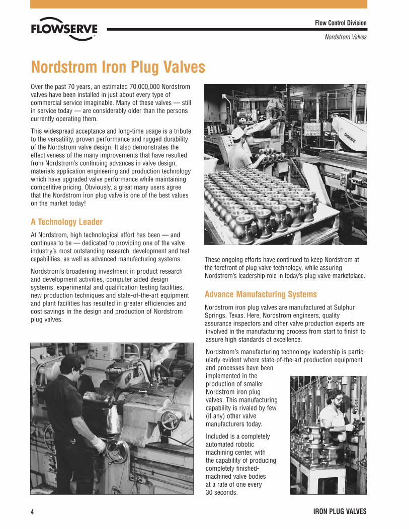
Advance Manufacturing SystemsNordstrom iron plug valves are manufactured at SulphurSprings, Texas. Here, Nordstrom engineers, qualityassurance inspectors and other valve production experts areinvolved in the manufacturing process from start to finish toassure high standards of excellence.
Nordstrom’s manufacturing technology leadership is partic-ularly evident where state-of-the-art production equipmentand processes have beenimplemented in theproduction of smallerNordstrom iron plugvalves. This manufacturingcapability is rivaled by few(if any) other valvemanufacturers today.
Included is a completelyautomated roboticmachining center, with the capability of producingcompletely finished-machined valve bodies at a rate of one every 30 seconds.
Flow Control Division
Nordstrom Valves
4 IRON PLUG VALVES
Nordstrom Iron Plug Valves
Flow Control Division
Nordstrom Valves
IRON PLUG VALVES 5
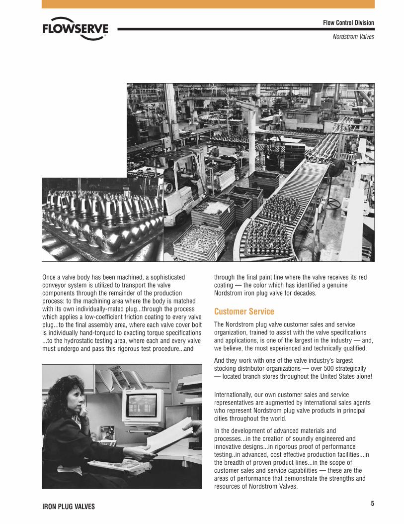
Once a valve body has been machined, a sophisticatedconveyor system is utilized to transport the valvecomponents through the remainder of the productionprocess: to the machining area where the body is matchedwith its own individually-mated plug...through the processwhich applies a low-coefficient friction coating to every valveplug...to the final assembly area, where each valve cover boltis individually hand-torqued to exacting torque specifications...to the hydrostatic testing area, where each and every valvemust undergo and pass this rigorous test procedure...and
through the final paint line where the valve receives its redcoating — the color which has identified a genuineNordstrom iron plug valve for decades.
Customer ServiceThe Nordstrom plug valve customer sales and serviceorganization, trained to assist with the valve specificationsand applications, is one of the largest in the industry — and,we believe, the most experienced and technically qualified.
And they work with one of the valve industry’s largeststocking distributor organizations — over 500 strategically— located branch stores throughout the United States alone!
Internationally, our own customer sales and servicerepresentatives are augmented by international sales agentswho represent Nordstrom plug valve products in principalcities throughout the world.
In the development of advanced materials andprocesses...in the creation of soundly engineered andinnovative designs...in rigorous proof of performancetesting..in advanced, cost effective production facilities...inthe breadth of proven product lines...in the scope ofcustomer sales and service capabilities — these are theareas of performance that demonstrate the strengths andresources of Nordstrom Valves.
Flow Control Division
Nordstrom Valves
IRON PLUG VALVES6
Flow Control Division
Nordstrom Valves
IRON PLUG VALVES 7
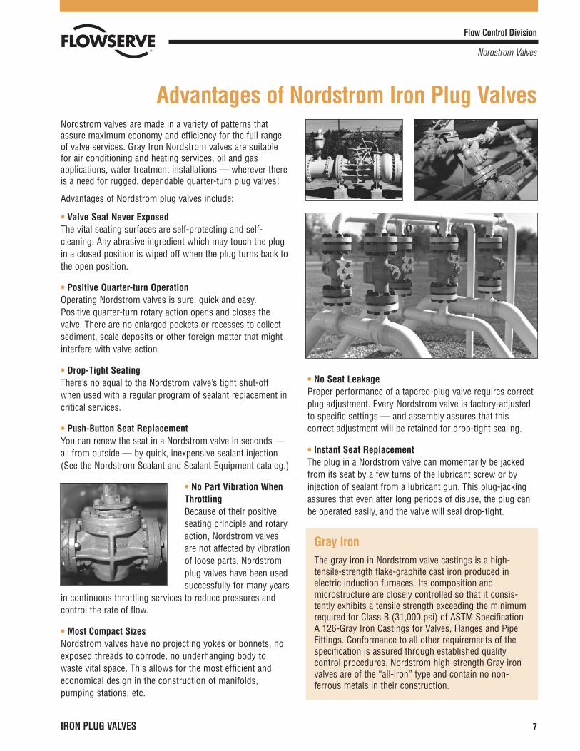
Nordstrom valves are made in a variety of patterns thatassure maximum economy and efficiency for the full rangeof valve services. Gray Iron Nordstrom valves are suitablefor air conditioning and heating services, oil and gasapplications, water treatment installations — wherever thereis a need for rugged, dependable quarter-turn plug valves!
Advantages of Nordstrom plug valves include:
• Valve Seat Never ExposedThe vital seating surfaces are self-protecting and self-cleaning. Any abrasive ingredient which may touch the plugin a closed position is wiped off when the plug turns back tothe open position.
• Positive Quarter-turn OperationOperating Nordstrom valves is sure, quick and easy.Positive quarter-turn rotary action opens and closes thevalve. There are no enlarged pockets or recesses to collectsediment, scale deposits or other foreign matter that mightinterfere with valve action.
• Drop-Tight SeatingThere’s no equal to the Nordstrom valve’s tight shut-offwhen used with a regular program of sealant replacement incritical services.
• Push-Button Seat ReplacementYou can renew the seat in a Nordstrom valve in seconds —all from outside — by quick, inexpensive sealant injection(See the Nordstrom Sealant and Sealant Equipment catalog.)
• No Part Vibration WhenThrottlingBecause of their positiveseating principle and rotaryaction, Nordstrom valvesare not affected by vibrationof loose parts. Nordstromplug valves have been usedsuccessfully for many years
in continuous throttling services to reduce pressures andcontrol the rate of flow.
• Most Compact SizesNordstrom valves have no projecting yokes or bonnets, noexposed threads to corrode, no underhanging body towaste vital space. This allows for the most efficient andeconomical design in the construction of manifolds,pumping stations, etc.
• No Seat LeakageProper performance of a tapered-plug valve requires correctplug adjustment. Every Nordstrom valve is factory-adjustedto specific settings — and assembly assures that thiscorrect adjustment will be retained for drop-tight sealing.
• Instant Seat ReplacementThe plug in a Nordstrom valve can momentarily be jackedfrom its seat by a few turns of the lubricant screw or byinjection of sealant from a lubricant gun. This plug-jackingassures that even after long periods of disuse, the plug canbe operated easily, and the valve will seal drop-tight.
Gray IronThe gray iron in Nordstrom valve castings is a high-tensile-strength flake-graphite cast iron produced inelectric induction furnaces. Its composition andmicrostructure are closely controlled so that it consis-tently exhibits a tensile strength exceeding the minimumrequired for Class B (31,000 psi) of ASTM SpecificationA 126-Gray Iron Castings for Valves, Flanges and PipeFittings. Conformance to all other requirements of thespecification is assured through established qualitycontrol procedures. Nordstrom high-strength Gray ironvalves are of the “all-iron” type and contain no non-ferrous metals in their construction.
Advantages of Nordstrom Iron Plug Valves
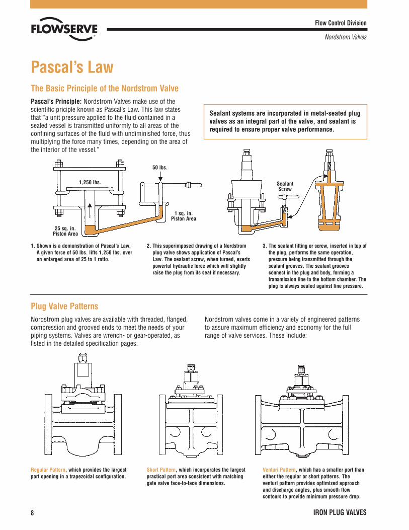
The Basic Principle of the Nordstrom ValvePascal’s Principle: Nordstrom Valves make use of thescientific priciple known as Pascal’s Law. This law statesthat “a unit pressure applied to the fluid contained in asealed vessel is transmitted uniformly to all areas of theconfining surfaces of the fluid with undiminished force, thusmultiplying the force many times, depending on the area ofthe interior of the vessel.”
Flow Control Division
Nordstrom Valves
8 IRON PLUG VALVES
Pascal’s Law
Sealant systems are incorporated in metal-seated plugvalves as an integral part of the valve, and sealant isrequired to ensure proper valve performance.
1. Shown is a demonstration of Pascal’s Law.A given force of 50 lbs. lifts 1,250 lbs. overan enlarged area of 25 to 1 ratio.
2. This superimposed drawing of a Nordstromplug valve shows application of Pascal’sLaw. The sealant screw, when turned, exertspowerful hydraulic force which will slightlyraise the plug from its seat if necessary.
3. The sealant fitting or screw, inserted in top ofthe plug, performs the same operation,pressure being transmitted through thesealant grooves. The sealant groovesconnect in the plug and body, forming atransmission line to the bottom chamber. Theplug is always sealed against line pressure.
Plug Valve PatternsNordstrom plug valves are available with threaded, flanged,compression and grooved ends to meet the needs of yourpiping systems. Valves are wrench- or gear-operated, aslisted in the detailed specification pages.
Nordstrom valves come in a variety of engineered patternsto assure maximum efficiency and economy for the fullrange of valve services. These include:
Regular Pattern, which provides the largestport opening in a trapezoidal configuration.
Short Pattern, which incorporates the largestpractical port area consistent with matchinggate valve face-to-face dimensions.
Venturi Pattern, which has a smaller port thaneither the regular or short patterns. Theventuri pattern provides optimized approachand discharge angles, plus smooth flowcontours to provide minimum pressure drop.
1,250 lbs.
25 sq. in.Piston Area
50 lbs.
1 sq. in.Piston Area
SealantScrew
Flow Control Division
Nordstrom Valves
IRON PLUG VALVES 9
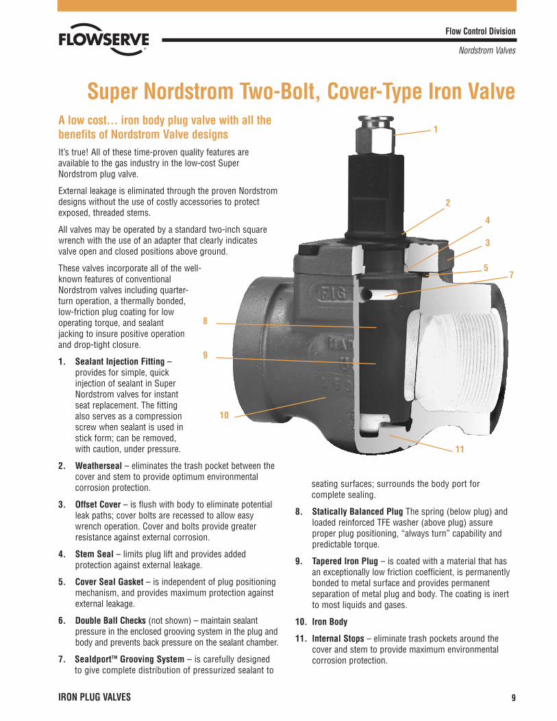
A low cost... iron body plug valve with all thebenefits of Nordstrom Valve designsIt’s true! All of these time-proven quality features areavailable to the gas industry in the low-cost SuperNordstrom plug valve.
External leakage is eliminated through the proven Nordstromdesigns without the use of costly accessories to protectexposed, threaded stems.
All valves may be operated by a standard two-inch squarewrench with the use of an adapter that clearly indicatesvalve open and closed positions above ground.
These valves incorporate all of the well-known features of conventionalNordstrom valves including quarter-turn operation, a thermally bonded,low-friction plug coating for lowoperating torque, and sealantjacking to insure positive operationand drop-tight closure.
1. Sealant Injection Fitting –provides for simple, quickinjection of sealant in SuperNordstrom valves for instantseat replacement. The fittingalso serves as a compressionscrew when sealant is used instick form; can be removed,with caution, under pressure.
2. Weatherseal – eliminates the trash pocket between thecover and stem to provide optimum environmentalcorrosion protection.
3. Offset Cover – is flush with body to eliminate potentialleak paths; cover bolts are recessed to allow easywrench operation. Cover and bolts provide greaterresistance against external corrosion.
4. Stem Seal – limits plug lift and provides addedprotection against external leakage.
5. Cover Seal Gasket – is independent of plug positioningmechanism, and provides maximum protection againstexternal leakage.
6. Double Ball Checks (not shown) – maintain sealantpressure in the enclosed grooving system in the plug andbody and prevents back pressure on the sealant chamber.
7. SealdportTM Grooving System – is carefully designedto give complete distribution of pressurized sealant to
seating surfaces; surrounds the body port forcomplete sealing.
8. Statically Balanced Plug The spring (below plug) andloaded reinforced TFE washer (above plug) assureproper plug positioning, “always turn” capability andpredictable torque.
9. Tapered Iron Plug – is coated with a material that hasan exceptionally low friction coefficient, is permanentlybonded to metal surface and provides permanentseparation of metal plug and body. The coating is inertto most liquids and gases.
10. Iron Body
11. Internal Stops – eliminate trash pockets around thecover and stem to provide maximum environmentalcorrosion protection.
Super Nordstrom Two-Bolt, Cover-Type Iron Valve
8
9
10
11
1
2
3
4
57

1. Wrench Square
2. Fixed Adjustment Gland
3. O-rings
4. Flexible Metal SealingDiaphragm and Gasket
5. Heavy-Wall Body
6. Plug
7. Sealant Fitting (Combination Sealant Screwand Gun Fitting)
8. Gland Cap Screw
9. Cover Cap Screw
10. Cover
11. Sealant Check Valve (Double Ball-Check PreventsEscape of Sealant)
12. Sealant Grooves (Provides “Sealdport” SealantSystem)
13. Sealant Chamber (Provides Plug “Jacking” Force)
In bolted gland-type valves, illustrated below, controlledplug motion is provided by flexing of the gland itself. Thebolted-type gland valves can be adjusted, if needed, butnormally require little attention for leak-free, easy-turningvalve performance.
The tapered plug is lapped individually with its matchingbody, providing perfect seating contact. The sealantchannels in the plug and body seats provide lubrication
which, together with the positive rotary action of thetapered-plug valve, protects the seating surfaces againstcorrosion, erosion, or accumulation of solid deposits. Thisvalve is designed with a heavy-wall body which isconstructed beyond its requirements as a pressure vesselfor its maximum rated working pressure to withstand thehigher-than-line sealant pressure and expected line stresses.
Flow Control Division
Nordstrom Valves
10 IRON PLUG VALVES
Nordstrom Bolted Gland-Type Iron Plug Valves
5
10
6
12
13
7
111 8
2
4
9
3
Flow Control Division
Nordstrom Valves
IRON PLUG VALVES 11
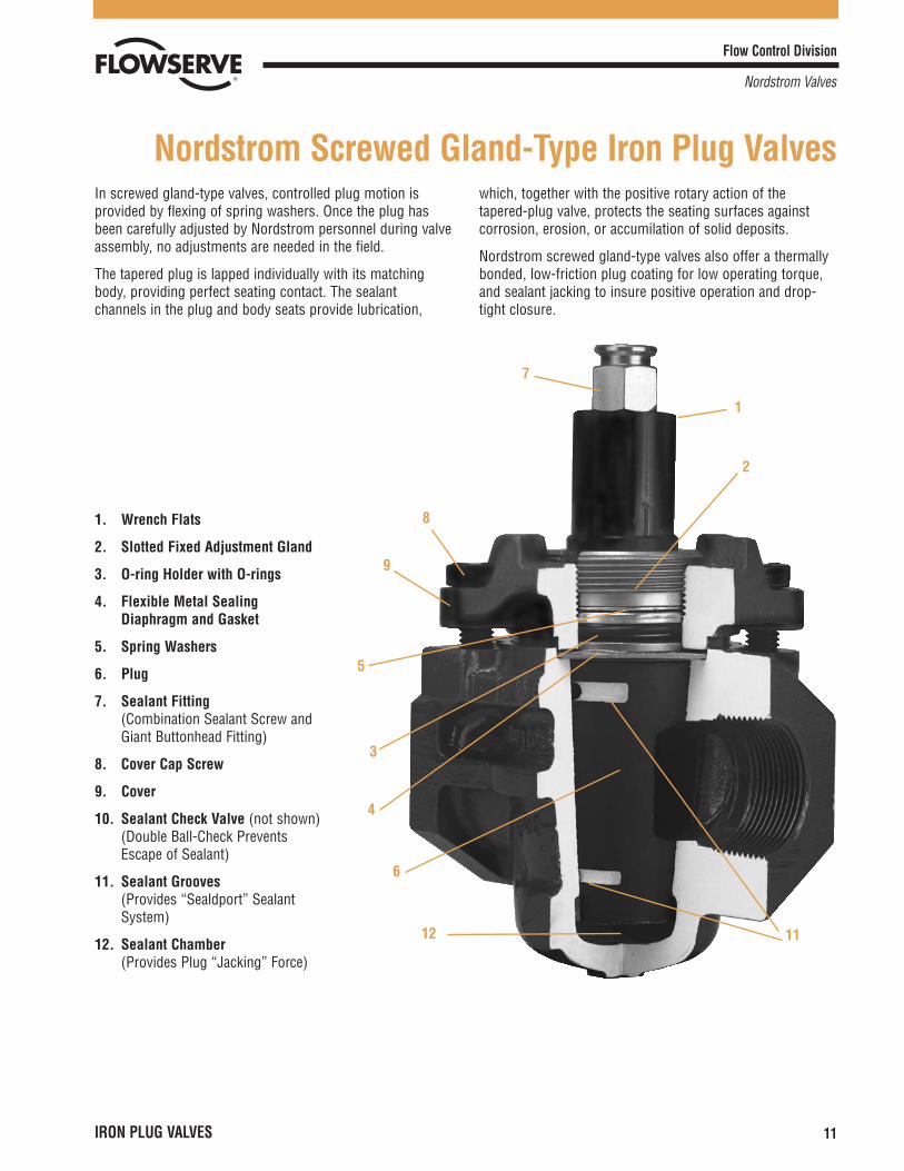
1. Wrench Flats
2. Slotted Fixed Adjustment Gland
3. O-ring Holder with O-rings
4. Flexible Metal SealingDiaphragm and Gasket
5. Spring Washers
6. Plug
7. Sealant Fitting(Combination Sealant Screw andGiant Buttonhead Fitting)
8. Cover Cap Screw
9. Cover
10. Sealant Check Valve (not shown) (Double Ball-Check PreventsEscape of Sealant)
11. Sealant Grooves(Provides “Sealdport” SealantSystem)
12. Sealant Chamber(Provides Plug “Jacking” Force)
In screwed gland-type valves, controlled plug motion isprovided by flexing of spring washers. Once the plug hasbeen carefully adjusted by Nordstrom personnel during valveassembly, no adjustments are needed in the field.
The tapered plug is lapped individually with its matchingbody, providing perfect seating contact. The sealantchannels in the plug and body seats provide lubrication,
which, together with the positive rotary action of thetapered-plug valve, protects the seating surfaces againstcorrosion, erosion, or accumilation of solid deposits.
Nordstrom screwed gland-type valves also offer a thermallybonded, low-friction plug coating for low operating torque,and sealant jacking to insure positive operation and drop-tight closure.
Nordstrom Screwed Gland-Type Iron Plug Valves
7
8
9
6
5
3
4
12
1
2
11
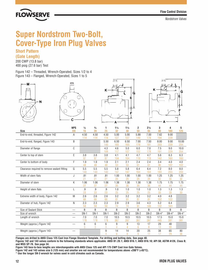
Short Pattern(Gate Length)200 CWP (13.8 bar)400 psig (27.6 bar) Test
Figure 142 – Threaded, Wrench-Operated, Sizes 1/2 to 4Figure 143 – Flanged, Wrench-Operated, Sizes 1 to 5
Flow Control Division
Nordstrom Valves
12 IRON PLUG VALVES
Super Nordstrom Two-Bolt, Cover-Type Iron Plug Valves
NPS ¹�₂ ³�₄ 1 1¹�₄ 1¹�₂ 2 2¹�₂ 3 4 5Size DN 15 20 25 32 40 50 65 80 100 125End-to-end, threaded, Figure 142 A 4.50 4.50 4.50 5.00 5.00 5.88 7.00 7.62 9.00
114 114 114 127 127 149 178 194 229End-to-end, flanged, Figure 143 B 5.50 6.50 6.50 7.00 7.50 8.00 9.00 10.00
140 165 165 178 191 203 229 254Diameter of flange C 4.3 4.6 5.0 6.0 7.0 7.5 9.0 10.0
109 117 127 152 178 191 229 254Center to top of stem E 3.8 3.8 3.8 4.1 4.1 4.7 4.7 5.6 6.3 6.3
97 97 97 104 104 119 119 142 160 160Center to bottom of body F 1.9 1.9 1.9 2.1 2.1 2.4 2.4 3.4 4.0 4.0
48 48 48 53 53 61 61 86 102 102Clearance required to remove sealant fitting G 5.5 5.5 5.5 5.8 5.8 6.4 6.4 7.2 8.0 8.0
140 140 140 147 147 163 163 183 203 203Width of stem flats J .81 .81 .81 1.00 1.00 1.00 1.00 1.25 1.25 1.25
21 21 21 25 25 25 25 32 32 32Diameter of stem K 1.06 1.06 1.06 1.38 1.38 1.38 1.38 1.75 1.75 1.75
27 27 27 35 35 35 35 44 44 44Height of stem flats L .9 .9 .9 1.0 1.0 1.0 1.0 1.3 1.3 1.3
23 23 23 25 25 25 25 33 33 33Extreme width of body, Figure 142 M 2.6 2.6 2.6 3.2 3.2 3.2 3.2 4.0 4.8
66 66 66 81 81 81 81 102 122Diameter of hub, Figure 142 N 2.3 2.3 2.3 2.9 2.9 3.6 4.3 5.2 6.4
58 58 58 74 74 91 109 132 163Size of Sealant Stick — B B B B B B B B B BSize of wrench — SN-1 SN-1 SN-1 SN-2 SN-2 SN-2 SN-2 SN-4* SN-4* SN-4*Length of wrench — 7.0 7.0 7.0 10.5 10.5 10.5 10.5 17.5 15.0 15.0
178 178 178 267 267 267 267 445 381 381Weight (approx.) Figure 142 — 6 6 6 9 9 13 17 29 48
3 3 3 4 4 6 8 13 22Weight (approx.) Figure 143 — 9 14 14 20 25 38 65 80
4 6 6 9 11 17 29 36Flanges are drilled to ANSI Class 125 Cast Iron Flange Standard Template. For drilling and bolting data, See page 40.Figures 142 and 143 valves conform to the following standards where applicable: ANSI B1.20.1; ANSI B16.1; ANSI B16.10; API 5B; ASTM A126, Class B;and MSS SP-78. See page 34.Figure 143 face-to-face lengths are interchangeable with ANSI Class 125 and API 175 CWP Cast Iron Gate Valves.Figure 142 and 143 valves size 5 (125 mm) and smaller are not recommended for temperatures above +200°F (+93°C).* Use the longer SN-3 wrench for valves used in cold climates such as Canada.
Flow Control Division
Nordstrom Valves
IRON PLUG VALVES 13
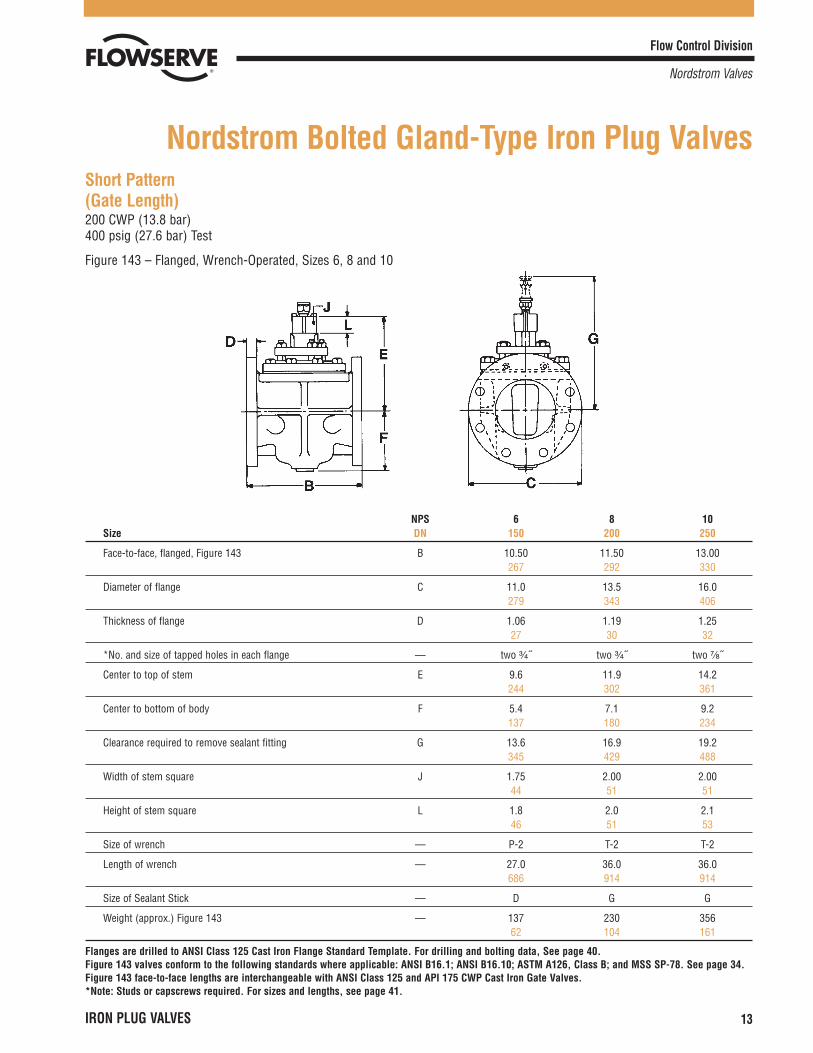
Short Pattern(Gate Length)200 CWP (13.8 bar)400 psig (27.6 bar) Test
Figure 143 – Flanged, Wrench-Operated, Sizes 6, 8 and 10
Nordstrom Bolted Gland-Type Iron Plug Valves
NPS 6 8 10Size DN 150 200 250
Face-to-face, flanged, Figure 143 B 10.50 11.50 13.00267 292 330
Diameter of flange C 11.0 13.5 16.0279 343 406
Thickness of flange D 1.06 1.19 1.2527 30 32
*No. and size of tapped holes in each flange — two ³�₄˝ two ³�₄˝ two ⁷�₈˝
Center to top of stem E 9.6 11.9 14.2244 302 361
Center to bottom of body F 5.4 7.1 9.2137 180 234
Clearance required to remove sealant fitting G 13.6 16.9 19.2345 429 488
Width of stem square J 1.75 2.00 2.0044 51 51
Height of stem square L 1.8 2.0 2.146 51 53
Size of wrench — P-2 T-2 T-2
Length of wrench — 27.0 36.0 36.0686 914 914
Size of Sealant Stick — D G G
Weight (approx.) Figure 143 — 137 230 35662 104 161
Flanges are drilled to ANSI Class 125 Cast Iron Flange Standard Template. For drilling and bolting data, See page 40.Figure 143 valves conform to the following standards where applicable: ANSI B16.1; ANSI B16.10; ASTM A126, Class B; and MSS SP-78. See page 34.Figure 143 face-to-face lengths are interchangeable with ANSI Class 125 and API 175 CWP Cast Iron Gate Valves.*Note: Studs or capscrews required. For sizes and lengths, see page 41.

Flow Control Division
Nordstrom Valves
14 IRON PLUG VALVES
Short Pattern(Gate Length)200 CWP (13.8 bar)400 psig (27.6 bar) Test
Figure 149 – Flanged, Worm-Gear-Operated, Sizes 6 through 12
NPS 6 8 10 12Size DN 150 200 250 300
Face-to-face, flanged, Figure 149 B 10.50 11.50 13.00 14.00267 292 330 356
Diameter of flange C 11.0 13.5 16.0 19.0279 343 406 483
Thickness of flange D 1.06 1.19 1.25 1.3127 30 32 33
*No. and size of tapped holes in each flange — two ³�₄˝ two ³�₄˝ two ⁷�₈˝ two ⁷�₈˝
Center to top of stem E 11.4 13.4 15.7 18.7289 340 399 475
Center to bottom of body F 5.4 7.1 9.2 10.6137 180 234 269
Clearance required to remove sealant fitting G 15.4 18.4 20.7 23.7391 467 526 602
Length of gear housing H 15.5 15.5 15.9 19.5394 394 404 495
Width of gear housing I 13.8 13.8 14.8 17.8351 351 376 452
Center to top of housing K 10.6 12.6 15.1 18.1269 320 384 460
Center of port to center of handwheel S 8.8 10.7 12.8 15.9224 272 325 404
Transverse centerline to center of worm shaft T 5.3 5.3 5.3 7.5135 135 135 191
Longitudinal centerline to face of handwheel U 12.6 12.6 13.3 14.5320 320 338 368
Overall diameter of handwheel W 20.0 20.0 23.0 26.0508 508 584 660
Turns of handwheel to open valve — 12¹�₂ 12¹�₂ 12¹�₂ 19¹�₂
Size of Sealant Stick — D G G G
Weight (approx.) Figure 149 — 228 321 458 760103 146 208 345
Flanges are drilled to ANSI Class 125 Cast Iron Flange Standard Template. For drilling and bolting data, See page 40.Figure 149 valves conform to the following standards where applicable: ANSI B16.1; ANSI B16.10; ASTM A126, Class B; and MSS SP-78. See page 34.*Note: Studs or capscrews required. For sizes and lengths, see page 41.
Flow Control Division
Nordstrom Valves
IRON PLUG VALVES 15
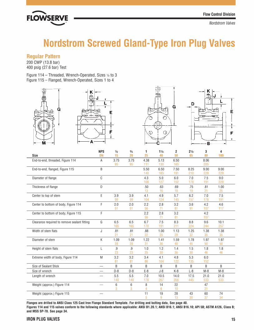
Regular Pattern200 CWP (13.8 bar)400 psig (27.6 bar) Test
Figure 114 – Threaded, Wrench-Operated, Sizes ¹�₂ to 3Figure 115 – Flanged, Wrench-Operated, Sizes 1 to 4
Nordstrom Screwed Gland-Type Iron Plug Valves
NPS ¹�₂ ³�₄ 1 1¹�₂ 2 2¹�₂ 3 4Size DN 15 20 25 40 50 65 80 100End-to-end, threaded, Figure 114 A 3.75 3.75 4.38 5.13 6.50 8.06
95 95 111 130 165 205End-to-end, flanged, Figure 115 B 5.50 6.50 7.50 8.25 9.00 9.00
140 165 191 210 229 229Diameter of flange C 4.3 5.0 6.0 7.0 7.5 9.0
108 127 152 178 191 229Thickness of flange D .50 .63 .69 .75 .81 1.00
13 16 18 19 21 25Center to top of stem E 3.9 3.9 4.1 4.9 5.7 6.2 7.0 7.5
99 99 104 124 145 157 178 191Center to bottom of body, Figure 114 F 2.0 2.0 2.2 2.8 3.2 3.6 4.2 4.6
51 51 56 71 81 91 107 117Center to bottom of body, Figure 115 F 2.2 2.8 3.2 4.2
56 71 81 107Clearance required to remove sealant fitting G 6.5 6.5 6.7 7.5 8.3 8.8 9.6 10.1
165 165 170 191 211 224 244 257Width of stem flats J .81 .81 .88 1.00 1.13 1.25 1.38 1.38
21 21 22 25 29 32 35 35Diameter of stem K 1.09 1.09 1.22 1.41 1.59 1.78 1.97 1.97
28 28 31 36 40 45 50 50Height of stem flats L .9 .9 1.0 1.2 1.4 1.5 1.8 1.8
23 23 25 30 36 38 46 46Extreme width of body, Figure 114 M 3.2 3.2 3.4 4.1 4.8 5.3 6.0
81 81 86 104 122 135 152Size of Sealant Stick — B B B B B B B BSize of wrench — D-8 D-8 E-8 J-8 K-8 L-8 M-8 M-8Length of wrench — 5.5 5.5 7.0 10.5 14.0 17.5 21.0 21.0
140 140 178 267 356 445 533 533Weight (approx.) Figure 114 — 6 6 8 14 22 47
3 3 4 6 10 21Weight (approx.) Figure 115 — 11 19 28 43 60 74
5 9 13 20 27 34
Flanges are drilled to ANSI Class 125 Cast Iron Flange Standard Template. For drilling and bolting data, See page 40.Figures 114 and 115 valves conform to the following standards where applicable: ANSI B1.20.1; ANSI B16.1; ANSI B16.10; API 5B; ASTM A126, Class B;and MSS SP-78. See page 34.
Flow Control Division
Nordstrom Valves
16 IRON PLUG VALVES
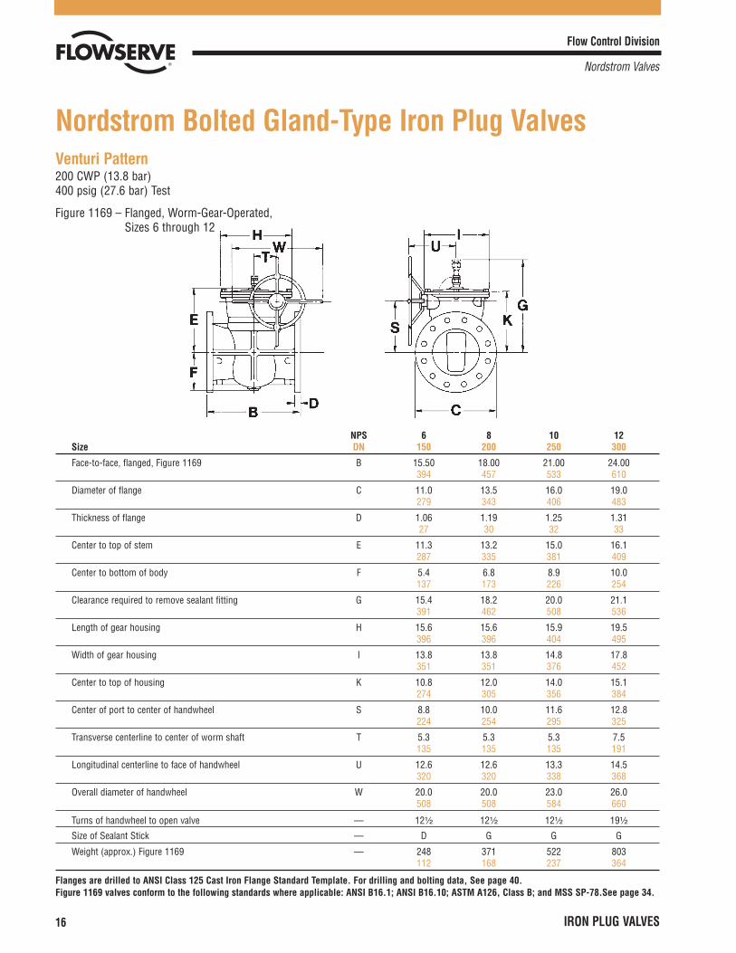
Venturi Pattern200 CWP (13.8 bar)400 psig (27.6 bar) Test
Figure 1169 – Flanged, Worm-Gear-Operated, Sizes 6 through 12
Nordstrom Bolted Gland-Type Iron Plug Valves
NPS 6 8 10 12Size DN 150 200 250 300
Face-to-face, flanged, Figure 1169 B 15.50 18.00 21.00 24.00394 457 533 610
Diameter of flange C 11.0 13.5 16.0 19.0279 343 406 483
Thickness of flange D 1.06 1.19 1.25 1.3127 30 32 33
Center to top of stem E 11.3 13.2 15.0 16.1287 335 381 409
Center to bottom of body F 5.4 6.8 8.9 10.0137 173 226 254
Clearance required to remove sealant fitting G 15.4 18.2 20.0 21.1391 462 508 536
Length of gear housing H 15.6 15.6 15.9 19.5396 396 404 495
Width of gear housing I 13.8 13.8 14.8 17.8351 351 376 452
Center to top of housing K 10.8 12.0 14.0 15.1274 305 356 384
Center of port to center of handwheel S 8.8 10.0 11.6 12.8224 254 295 325
Transverse centerline to center of worm shaft T 5.3 5.3 5.3 7.5135 135 135 191
Longitudinal centerline to face of handwheel U 12.6 12.6 13.3 14.5320 320 338 368
Overall diameter of handwheel W 20.0 20.0 23.0 26.0508 508 584 660
Turns of handwheel to open valve — 12¹�₂ 12¹�₂ 12¹�₂ 19¹�₂
Size of Sealant Stick — D G G G
Weight (approx.) Figure 1169 — 248 371 522 803112 168 237 364
Flanges are drilled to ANSI Class 125 Cast Iron Flange Standard Template. For drilling and bolting data, See page 40.Figure 1169 valves conform to the following standards where applicable: ANSI B16.1; ANSI B16.10; ASTM A126, Class B; and MSS SP-78.See page 34.
Flow Control Division
Nordstrom Valves
IRON PLUG VALVES 17
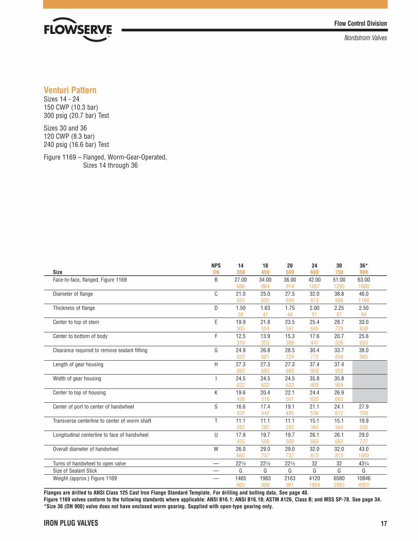
Venturi PatternSizes 14 - 24150 CWP (10.3 bar)300 psig (20.7 bar) Test
Sizes 30 and 36120 CWP (8.3 bar)240 psig (16.6 bar) Test
Figure 1169 – Flanged, Worm-Gear-Operated, Sizes 14 through 36
NPS 14 18 20 24 30 36*Size DN 350 450 500 600 750 900Face-to-face, flanged, Figure 1169 B 27.00 34.00 36.00 42.00 51.00 63.00
686 864 914 1067 1295 1600Diameter of flange C 21.0 25.0 27.5 32.0 38.8 46.0
533 635 699 813 986 1168Thickness of flange D 1.50 1.63 1.75 2.00 2.25 2.50
38 41 44 51 57 64Center to top of stem E 19.9 21.8 23.5 25.4 28.7 33.0
505 554 597 645 729 838Center to bottom of body F 12.5 13.9 15.3 17.6 20.7 25.6
318 353 389 447 526 650Clearance required to remove sealant fitting G 24.9 26.8 28.5 30.4 33.7 38.0
632 681 724 772 856 965Length of gear housing H 27.3 27.3 27.3 37.4 37.4
693 693 693 950 950Width of gear housing I 24.5 24.5 24.5 35.8 35.8
622 622 622 909 909Center to top of housing K 19.6 20.4 22.1 24.4 26.9
498 518 561 620 683Center of port to center of handwheel S 16.6 17.4 19.1 21.1 24.1 27.9
422 442 485 536 612 709Transverse centerline to center of worm shaft T 11.1 11.1 11.1 15.1 15.1 19.9
282 282 282 384 384 505Longitudinal centerline to face of handwheel U 17.9 19.7 19.7 26.1 26.1 29.0
455 500 500 663 663 737Overall diameter of handwheel W 26.0 29.0 29.0 32.0 32.0 43.0
660 737 737 813 813 1092Turns of handwheel to open valve — 22¹�₂ 22¹�₂ 22¹�₂ 32 32 43¹�₄
Size of Sealant Stick — G G G G G GWeight (approx.) Figure 1169 — 1465 1983 2163 4120 6580 10846
665 899 981 1869 2985 4920Flanges are drilled to ANSI Class 125 Cast Iron Flange Standard Template. For drilling and bolting data, See page 40.Figure 1169 valves conform to the following standards where applicable: ANSI B16.1; ANSI B16.10; ASTM A126, Class B; and MSS SP-78. See page 34.*Size 36 (DN 900) valve does not have enclosed worm gearing. Supplied with open-type gearing only.
Flow Control Division
Nordstrom Valves
18 IRON PLUG VALVES
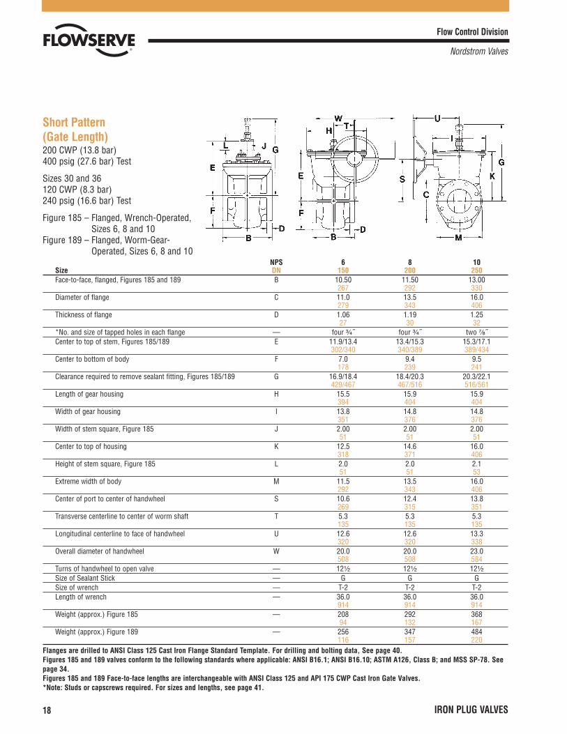
Short Pattern(Gate Length)200 CWP (13.8 bar)400 psig (27.6 bar) Test
Sizes 30 and 36120 CWP (8.3 bar)240 psig (16.6 bar) Test
Figure 185 – Flanged, Wrench-Operated,Sizes 6, 8 and 10
Figure 189 – Flanged, Worm-Gear-Operated, Sizes 6, 8 and 10
NPS 6 8 10Size DN 150 200 250Face-to-face, flanged, Figures 185 and 189 B 10.50 11.50 13.00
267 292 330Diameter of flange C 11.0 13.5 16.0
279 343 406Thickness of flange D 1.06 1.19 1.25
27 30 32*No. and size of tapped holes in each flange — four ³�₄˝ four ³�₄˝ two ⁷�₈˝Center to top of stem, Figures 185/189 E 11.9/13.4 13.4/15.3 15.3/17.1
302/340 340/389 389/434Center to bottom of body F 7.0 9.4 9.5
178 239 241Clearance required to remove sealant fitting, Figures 185/189 G 16.9/18.4 18.4/20.3 20.3/22.1
429/467 467/516 516/561Length of gear housing H 15.5 15.9 15.9
394 404 404Width of gear housing I 13.8 14.8 14.8
351 376 376Width of stem square, Figure 185 J 2.00 2.00 2.00
51 51 51Center to top of housing K 12.5 14.6 16.0
318 371 406Height of stem square, Figure 185 L 2.0 2.0 2.1
51 51 53Extreme width of body M 11.5 13.5 16.0
292 343 406Center of port to center of handwheel S 10.6 12.4 13.8
269 315 351Transverse centerline to center of worm shaft T 5.3 5.3 5.3
135 135 135Longitudinal centerline to face of handwheel U 12.6 12.6 13.3
320 320 338Overall diameter of handwheel W 20.0 20.0 23.0
508 508 584Turns of handwheel to open valve — 12¹�₂ 12¹�₂ 12¹�₂
Size of Sealant Stick — G G GSize of wrench — T-2 T-2 T-2Length of wrench — 36.0 36.0 36.0
914 914 914Weight (approx.) Figure 185 — 208 292 368
94 132 167Weight (approx.) Figure 189 — 256 347 484
116 157 220Flanges are drilled to ANSI Class 125 Cast Iron Flange Standard Template. For drilling and bolting data, See page 40.Figures 185 and 189 valves conform to the following standards where applicable: ANSI B16.1; ANSI B16.10; ASTM A126, Class B; and MSS SP-78. Seepage 34.Figures 185 and 189 Face-to-face lengths are interchangeable with ANSI Class 125 and API 175 CWP Cast Iron Gate Valves.*Note: Studs or capscrews required. For sizes and lengths, see page 41.
Flow Control Division
Nordstrom Valves
IRON PLUG VALVES 19
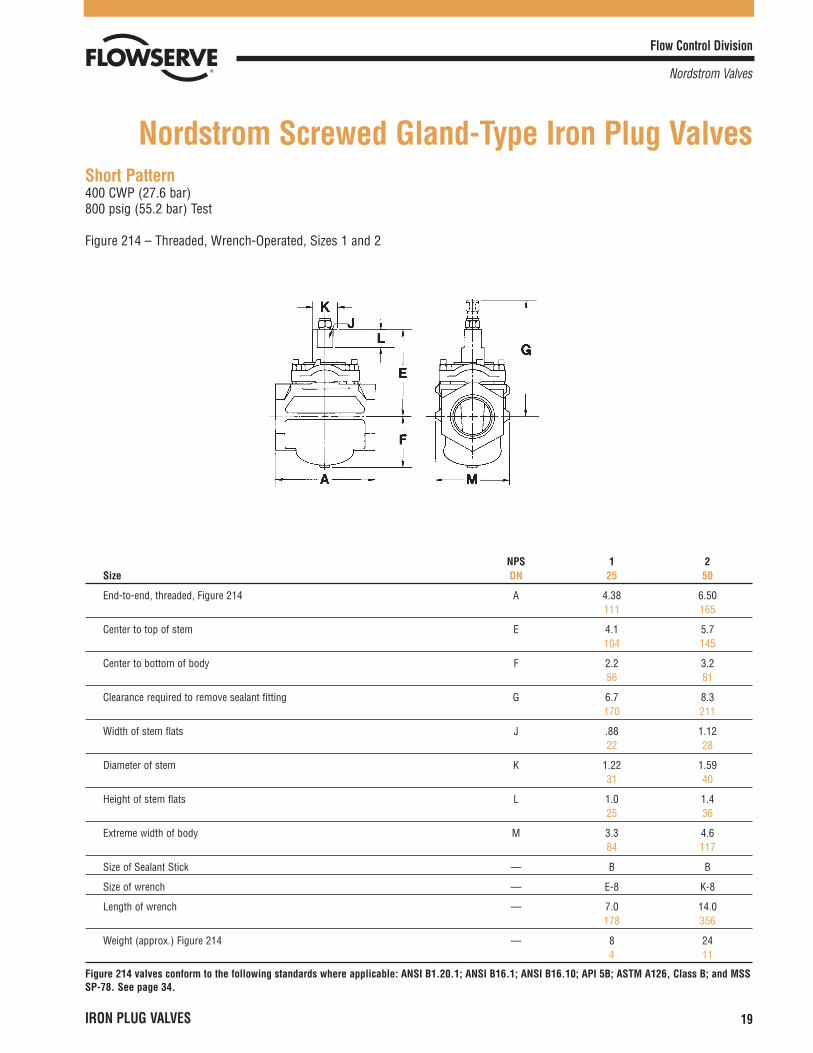
Short Pattern400 CWP (27.6 bar)800 psig (55.2 bar) Test
Figure 214 – Threaded, Wrench-Operated, Sizes 1 and 2
NPS 1 2Size DN 25 50
End-to-end, threaded, Figure 214 A 4.38 6.50111 165
Center to top of stem E 4.1 5.7104 145
Center to bottom of body F 2.2 3.256 81
Clearance required to remove sealant fitting G 6.7 8.3170 211
Width of stem flats J .88 1.1222 28
Diameter of stem K 1.22 1.5931 40
Height of stem flats L 1.0 1.425 36
Extreme width of body M 3.3 4.684 117
Size of Sealant Stick — B B
Size of wrench — E-8 K-8
Length of wrench — 7.0 14.0178 356
Weight (approx.) Figure 214 — 8 244 11
Figure 214 valves conform to the following standards where applicable: ANSI B1.20.1; ANSI B16.1; ANSI B16.10; API 5B; ASTM A126, Class B; and MSSSP-78. See page 34.
Nordstrom Screwed Gland-Type Iron Plug Valves

Flow Control Division
Nordstrom Valves
20 IRON PLUG VALVES
Regular Pattern200 CWP (13.8 bar)400 psig (27.6 bar) Test
Figure 164 – Threaded, Wrench-Operated, Size 4Figure 165 – Flanged, Wrench-Operated, Sizes 4, 6 and 8
Nordstrom Bolted Gland-Type Iron Plug Valves
NPS 4 6 8Size DN 100 150 200End-to-end, threaded, Figure 164 A 10.00
254Face-to-face, flanged, Figure 165 B 12.00 15.50 18.00
305 394 457Diameter of flange C 9.0 11.0 13.5
229 279 343Thickness of flange D 1.00 1.06 1.19
25 27 30Center to top of stem E 9.6 12.1 14.7
244 307 373Center to bottom of body, Figure 164 F 5.4
137Center to bottom of body, Figure 165 F 5.5 7.5 9.4
140 191 239Clearance required to remove sealant fitting G 13.4 17.1 19.7
340 434 500Width of stem square J 1.75 2.00 2.44
44 51 62Height of stem square L 1.8 2.1 2.4
46 53 61Extreme width of body, Figure 164 M 8.9
226Extreme width of body, Figure 165 M 8.9 13.5 17.0
226 343 432Size of wrench — P-2 T-2 V-2Length of wrench — 27.0 36.0 48.0
686 914 1219Size of Sealant Stick — D G GWeight (approx.) Figure 164 — 107
49Weight (approx.) Figure 165 — 129 277 500
59 126 227
Flanges are drilled to ANSI Class 125 Cast Iron Flange Standard Template. For drilling and bolting data, See page 40.Figures 164 and 165 valves conform to the following standards where applicable: ANSI B1.20.1; ANSI B16.1; ANSI B16.10; API 5B; ASTM A126, Class B; and MSS SP-78. See page 34.
Flow Control Division
Nordstrom Valves
IRON PLUG VALVES 21
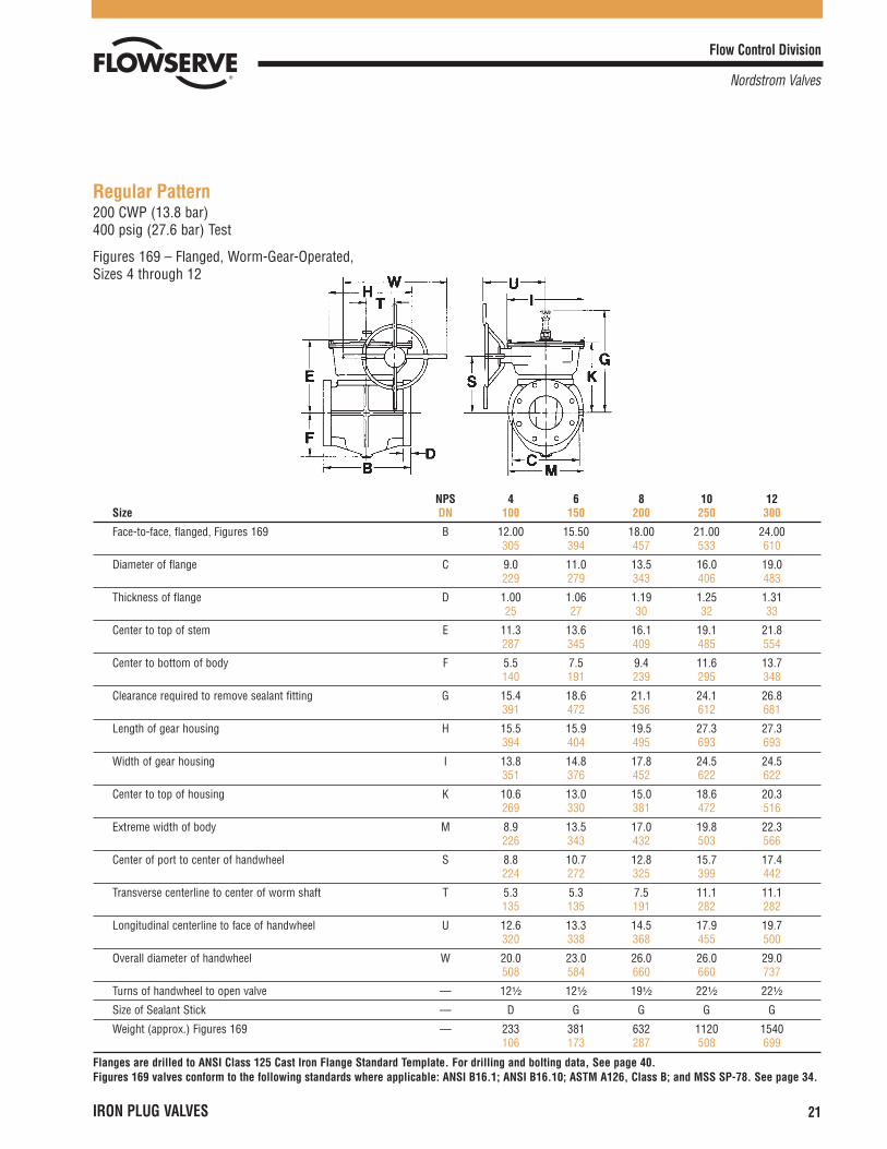
Regular Pattern200 CWP (13.8 bar)400 psig (27.6 bar) Test
Figures 169 – Flanged, Worm-Gear-Operated, Sizes 4 through 12
NPS 4 6 8 10 12Size DN 100 150 200 250 300
Face-to-face, flanged, Figures 169 B 12.00 15.50 18.00 21.00 24.00305 394 457 533 610
Diameter of flange C 9.0 11.0 13.5 16.0 19.0229 279 343 406 483
Thickness of flange D 1.00 1.06 1.19 1.25 1.3125 27 30 32 33
Center to top of stem E 11.3 13.6 16.1 19.1 21.8287 345 409 485 554
Center to bottom of body F 5.5 7.5 9.4 11.6 13.7140 191 239 295 348
Clearance required to remove sealant fitting G 15.4 18.6 21.1 24.1 26.8391 472 536 612 681
Length of gear housing H 15.5 15.9 19.5 27.3 27.3394 404 495 693 693
Width of gear housing I 13.8 14.8 17.8 24.5 24.5351 376 452 622 622
Center to top of housing K 10.6 13.0 15.0 18.6 20.3269 330 381 472 516
Extreme width of body M 8.9 13.5 17.0 19.8 22.3226 343 432 503 566
Center of port to center of handwheel S 8.8 10.7 12.8 15.7 17.4224 272 325 399 442
Transverse centerline to center of worm shaft T 5.3 5.3 7.5 11.1 11.1135 135 191 282 282
Longitudinal centerline to face of handwheel U 12.6 13.3 14.5 17.9 19.7320 338 368 455 500
Overall diameter of handwheel W 20.0 23.0 26.0 26.0 29.0508 584 660 660 737
Turns of handwheel to open valve — 12¹�₂ 12¹�₂ 19¹�₂ 22¹�₂ 22¹�₂
Size of Sealant Stick — D G G G G
Weight (approx.) Figures 169 — 233 381 632 1120 1540106 173 287 508 699
Flanges are drilled to ANSI Class 125 Cast Iron Flange Standard Template. For drilling and bolting data, See page 40.Figures 169 valves conform to the following standards where applicable: ANSI B16.1; ANSI B16.10; ASTM A126, Class B; and MSS SP-78. See page 34.
Flow Control Division
Nordstrom Valves
22 IRON PLUG VALVES
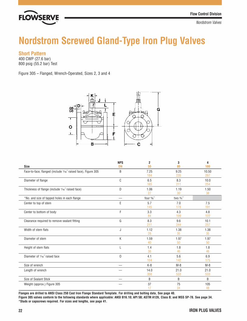
Short Pattern400 CWP (27.6 bar)800 psig (55.2 bar) Test
Figure 305 – Flanged, Wrench-Operated, Sizes 2, 3 and 4
Nordstrom Screwed Gland-Type Iron Plug Valves
NPS 2 3 4Size DN 50 80 100Face-to-face, flanged (include ¹�₁₆˝ raised face), Figure 305 B 7.25 9.25 10.50
184 235 267Diameter of flange C 6.5 8.3 10.0
165 211 254Thickness of flange (include ¹�₁₆˝ raised face) D 1.06 1.19 1.50
27 30 38*No. and size of tapped holes in each flange — four ⁵�₈˝ two ³�₄˝Center to top of stem E 5.7 7.0 7.5
145 178 191Center to bottom of body F 3.3 4.3 4.8
84 109 122Clearance required to remove sealant fitting G 8.3 9.6 10.1
211 244 257Width of stem flats J 1.12 1.38 1.38
28 35 35Diameter of stem K 1.59 1.97 1.97
40 50 50Height of stem flats L 1.4 1.8 1.8
36 46 46Diameter of ¹�₁₆˝ raised face O 4.1 5.6 6.9
104 142 175Size of wrench — K-8 M-8 M-8Length of wrench — 14.0 21.0 21.0
356 533 533Size of Sealant Stick — B B BWeight (approx.) Figure 305 — 37 75 105
17 34 48
Flanges are drilled to ANSI Class 250 Cast Iron Flange Standard Template. For drilling and bolting data, See page 40.Figure 305 valves conform to the following standards where applicable: ANSI B16.10; API 5B; ASTM A126, Class B; and MSS SP-78. See page 34.*Studs or capscrews required. For sizes and lengths, see page 41.
Flow Control Division
Nordstrom Valves
IRON PLUG VALVES 23
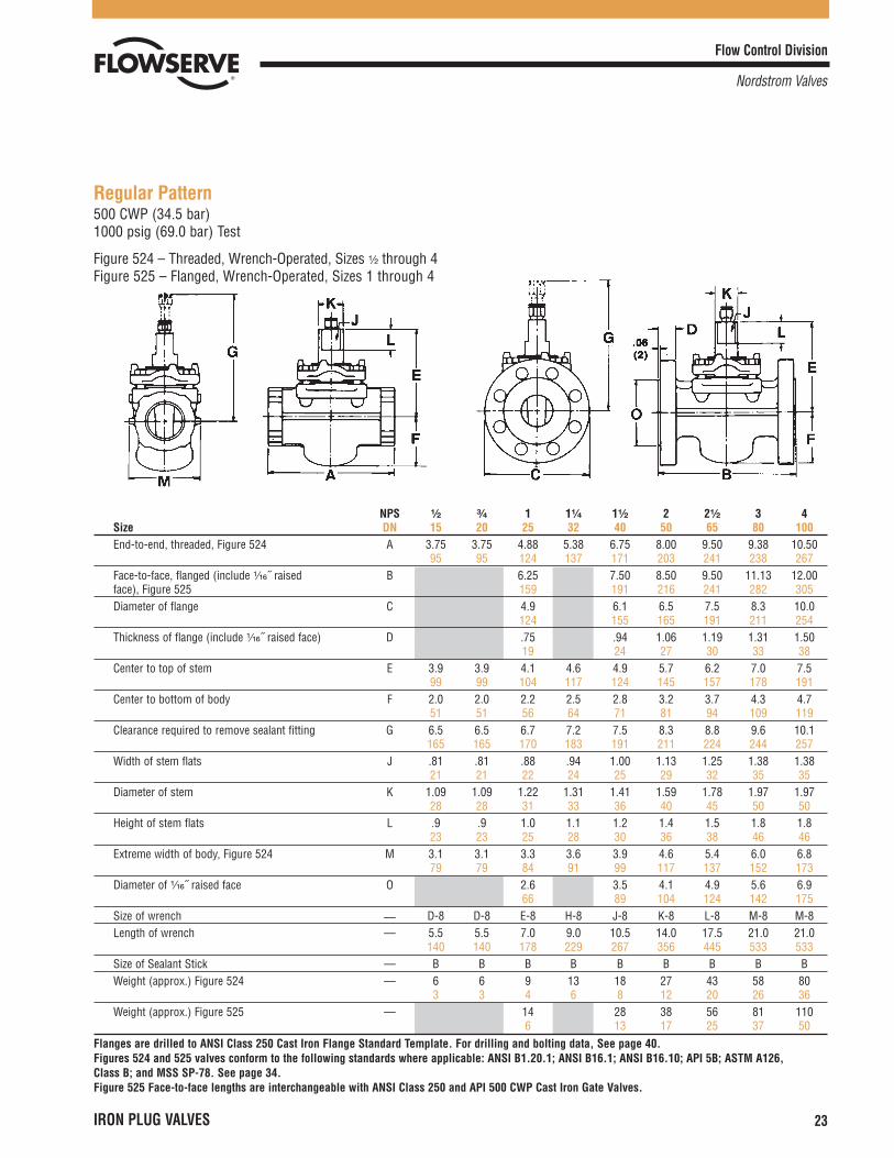
Regular Pattern500 CWP (34.5 bar)1000 psig (69.0 bar) Test
Figure 524 – Threaded, Wrench-Operated, Sizes ¹�₂ through 4Figure 525 – Flanged, Wrench-Operated, Sizes 1 through 4
NPS ¹�₂ ³�₄ 1 1¹�₄ 1¹�₂ 2 2¹�₂ 3 4Size DN 15 20 25 32 40 50 65 80 100End-to-end, threaded, Figure 524 A 3.75 3.75 4.88 5.38 6.75 8.00 9.50 9.38 10.50
95 95 124 137 171 203 241 238 267Face-to-face, flanged (include ¹�₁₆˝ raised B 6.25 7.50 8.50 9.50 11.13 12.00face), Figure 525 159 191 216 241 282 305Diameter of flange C 4.9 6.1 6.5 7.5 8.3 10.0
124 155 165 191 211 254Thickness of flange (include ¹�₁₆˝ raised face) D .75 .94 1.06 1.19 1.31 1.50
19 24 27 30 33 38Center to top of stem E 3.9 3.9 4.1 4.6 4.9 5.7 6.2 7.0 7.5
99 99 104 117 124 145 157 178 191Center to bottom of body F 2.0 2.0 2.2 2.5 2.8 3.2 3.7 4.3 4.7
51 51 56 64 71 81 94 109 119Clearance required to remove sealant fitting G 6.5 6.5 6.7 7.2 7.5 8.3 8.8 9.6 10.1
165 165 170 183 191 211 224 244 257Width of stem flats J .81 .81 .88 .94 1.00 1.13 1.25 1.38 1.38
21 21 22 24 25 29 32 35 35Diameter of stem K 1.09 1.09 1.22 1.31 1.41 1.59 1.78 1.97 1.97
28 28 31 33 36 40 45 50 50Height of stem flats L .9 .9 1.0 1.1 1.2 1.4 1.5 1.8 1.8
23 23 25 28 30 36 38 46 46Extreme width of body, Figure 524 M 3.1 3.1 3.3 3.6 3.9 4.6 5.4 6.0 6.8
79 79 84 91 99 117 137 152 173Diameter of ¹�₁₆˝ raised face O 2.6 3.5 4.1 4.9 5.6 6.9
66 89 104 124 142 175Size of wrench — D-8 D-8 E-8 H-8 J-8 K-8 L-8 M-8 M-8Length of wrench — 5.5 5.5 7.0 9.0 10.5 14.0 17.5 21.0 21.0
140 140 178 229 267 356 445 533 533Size of Sealant Stick — B B B B B B B B BWeight (approx.) Figure 524 — 6 6 9 13 18 27 43 58 80
3 3 4 6 8 12 20 26 36Weight (approx.) Figure 525 — 14 28 38 56 81 110
6 13 17 25 37 50Flanges are drilled to ANSI Class 250 Cast Iron Flange Standard Template. For drilling and bolting data, See page 40.Figures 524 and 525 valves conform to the following standards where applicable: ANSI B1.20.1; ANSI B16.1; ANSI B16.10; API 5B; ASTM A126, Class B; and MSS SP-78. See page 34.Figure 525 Face-to-face lengths are interchangeable with ANSI Class 250 and API 500 CWP Cast Iron Gate Valves.
Flow Control Division
Nordstrom Valves
24 IRON PLUG VALVES
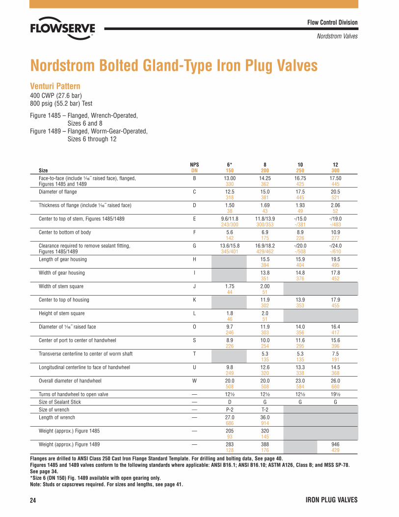
Venturi Pattern400 CWP (27.6 bar)800 psig (55.2 bar) Test
Figure 1485 – Flanged, Wrench-Operated, Sizes 6 and 8
Figure 1489 – Flanged, Worm-Gear-Operated, Sizes 6 through 12
Nordstrom Bolted Gland-Type Iron Plug Valves
NPS 6* 8 10 12Size DN 150 200 250 300Face-to-face (include ¹�₁₆˝ raised face), flanged, B 13.00 14.25 16.75 17.50Figures 1485 and 1489 330 362 425 445Diameter of flange C 12.5 15.0 17.5 20.5
318 381 445 521Thickness of flange (include ¹�₁₆˝ raised face) D 1.50 1.69 1.93 2.06
38 43 49 52Center to top of stem, Figures 1485/1489 E 9.6/11.8 11.8/13.9 -/15.0 -/19.0
243/300 300/353 -/381 -/483Center to bottom of body F 5.6 6.9 8.9 10.9
142 175 226 277Clearance required to remove sealant fitting, G 13.6/15.8 16.9/18.2 -/20.0 -/24.0Figures 1485/1489 345/401 429/462 -/508 -/610Length of gear housing H 15.5 15.9 19.5
394 404 495Width of gear housing I 13.8 14.8 17.8
351 376 452Width of stem square J 1.75 2.00
44 51Center to top of housing K 11.9 13.9 17.9
302 353 455Height of stem square L 1.8 2.0
46 51Diameter of ¹�₁₆˝ raised face O 9.7 11.9 14.0 16.4
246 303 356 417Center of port to center of handwheel S 8.9 10.0 11.6 15.6
226 254 295 396Transverse centerline to center of worm shaft T 5.3 5.3 7.5
135 135 191Longitudinal centerline to face of handwheel U 9.8 12.6 13.3 14.5
249 320 338 368Overall diameter of handwheel W 20.0 20.0 23.0 26.0
508 508 584 660Turns of handwheel to open valve — 12¹�₂ 12¹�₂ 12¹�₂ 19¹�₂
Size of Sealant Stick — D G G GSize of wrench — P-2 T-2Length of wrench — 27.0 36.0
686 914Weight (approx.) Figure 1485 — 205 320
93 145Weight (approx.) Figure 1489 — 283 388 946
128 176 429
Flanges are drilled to ANSI Class 250 Cast Iron Flange Standard Template. For drilling and bolting data, See page 40.Figures 1485 and 1489 valves conform to the following standards where applicable: ANSI B16.1; ANSI B16.10; ASTM A126, Class B; and MSS SP-78.See page 34.*Size 6 (DN 150) Fig. 1489 available with open gearing only.Note: Studs or capscrews required. For sizes and lengths, see page 41.

Flow Control Division
Nordstrom Valves
IRON PLUG VALVES 25
Venturi Pattern300 CWP (20.7 bar)600 psig (41.4 bar) Test
Figure 1489 – Flanged, Worm-Gear-Operated, Sizes 16 through 24
NPS 16 18 20 24Size DN 400 450 500 600Face-to-face (include ¹�₁₆˝ raised face), flanged, B 33.00 36.00 39.00 45.00Figure 1489 838 914 991 1143Diameter of flange C 25.5 28.0 30.5 36.0
648 711 775 914Thickness of flange (include ¹�₁₆˝ raised face) D 2.44 2.50 2.69 2.94
62 64 68 75Center to top of stem E 20.0 21.8 23.5 25.4
508 554 597 645Center to bottom of body F 13.0 14.5 15.9 17.9
330 368 404 455Clearance required to remove sealant fitting G 25.0 26.8 28.5 30.4
635 681 724 772Length of gear housing H 27.3 27.3 27.3 37.4
693 693 693 950Width of gear housing I 24.5 24.5 24.5 35.8
622 622 622 909Center to top of housing K 19.6 20.4 22.1 23.9
498 518 561 607Diameter of ¹�₁₆˝ raised face O 21.0 23.3 25.5 30.3
533 592 648 770Center of port to center of handwheel S 16.6 17.4 19.1 21.1
422 442 485 536Transverse centerline to center of worm shaft T 11.1 11.1 11.1 15.1
282 282 282 384Longitudinal centerline to face of handwheel U 17.9 19.7 19.7 26.1
455 500 500 663Overall diameter of handwheel W 26.0 29.0 29.0 32.0
660 737 737 813Turns of handwheel to open valve - 22¹�₂ 22¹�₂ 22¹�₂ 32Size of Sealant Stick - G G G GWeight (approx.) Figure 1489 - 1815 2515 2975 4220
823 1141 1349 1914
Flanges are drilled to ANSI Class 250 Cast Iron Flange Standard Template. For drilling and bolting data, See page 40.Figure 1489 valves conform to the following standards where applicable: ANSI B16.1; ANSI B16.10; ASTM A126, Class B; and MSS SP-78. See page 34.Note: Studs or capscrews required. For sizes and lengths, see page 41.

Flow Control Division
Nordstrom Valves
26 IRON PLUG VALVES
Regular Pattern400 CWP (27.6 bar)800 psig (55.2 bar) Test
Figure 265 – Flanged, Wrench-Operated, Sizes 4 and 6
NPS 4 6Size DN 100 150
Face-to-face, flanged, Figure 265 B 13.00 16.75330 425
Diameter of flange C 10.0 12.5254 318
Thickness of flange D 1.37 1.6835 43
Center to top of stem E 9.6 12.1244 307
Center to bottom of body F 5.7 7.8145 198
Clearance required to remove sealant fitting G 13.5 17.1343 434
Width of stem square J 1.75 2.0044 51
Height of stem square L 1.8 2.146 53
Extreme width of body M 10.0 14.3254 363
Diameter of ¹�₁₆˝ raised face O 6.9 9.6175 244
Size of wrench — P-2 T-2
Length of wrench — 27.0 36.0686 914
Size of Sealant Stick — D G
Weight (approx.) Figure 265 — 184 38583 175
Flanges are drilled to ANSI Class 250 Cast Iron Flange Standard Template. For drilling and bolting data, See page 40.Figure 265 valves conform to the following standards where applicable: ANSI B16.1; ANSI B16.10 (size 6 [DN 150] only); ASTM A126, Class B; and MSSSP-78. See page 34.
Flow Control Division
Nordstrom Valves
IRON PLUG VALVES 27
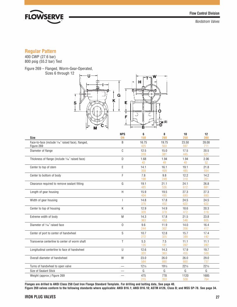
Regular Pattern400 CWP (27.6 bar)800 psig (55.2 bar) Test
Figure 269 – Flanged, Worm-Gear-Operated, Sizes 6 through 12
NPS 6 8 10 12Size DN 150 200 250 300Face-to-face (include ¹�₁₆˝ raised face), flanged, B 16.75 19.75 23.50 28.00Figure 269 425 503 597 711Diameter of flange C 12.5 15.0 17.5 20.5
318 381 445 521Thickness of flange (include ¹�₁₆˝ raised face) D 1.68 1.94 1.94 2.06
43 49 49 52Center to top of stem E 14.1 16.1 19.1 21.8
358 409 485 554Center to bottom of body F 7.8 9.8 12.2 14.2
198 249 310 361Clearance required to remove sealant fitting G 19.1 21.1 24.1 26.8
485 536 612 681Length of gear housing H 15.9 19.5 27.3 27.3
404 495 693 693Width of gear housing I 14.8 17.8 24.5 24.5
376 452 622 622Center to top of housing K 12.9 14.9 18.6 20.3
328 378 472 516Extreme width of body M 14.3 17.8 21.5 23.8
363 452 546 605Diameter of ¹�₁₆˝ raised face O 9.6 11.9 14.0 16.4
244 302 356 417Center of port to center of handwheel S 10.7 12.8 15.7 17.4
272 325 399 442Transverse centerline to center of worm shaft T 5.3 7.5 11.1 11.1
135 191 282 282Longitudinal centerline to face of handwheel U 12.6 14.3 17.9 19.7
320 363 455 500Overall diameter of handwheel W 23.0 26.0 26.0 29.0
584 660 660 737Turns of handwheel to open valve — 12¹�₂ 19¹�₂ 22¹�₂ 22¹�₂
Size of Sealant Stick — G G G GWeight (approx.) Figure 269 — 475 778 1120 1685
215 353 508 764
Flanges are drilled to ANSI Class 250 Cast Iron Flange Standard Template. For drilling and bolting data, See page 40.Figure 269 valves conform to the following standards where applicable: ANSI B16.1; ANSI B16.10; ASTM A126, Class B; and MSS SP-78. See page 34.
Flow Control Division
Nordstrom Valves
28 IRON PLUG VALVES
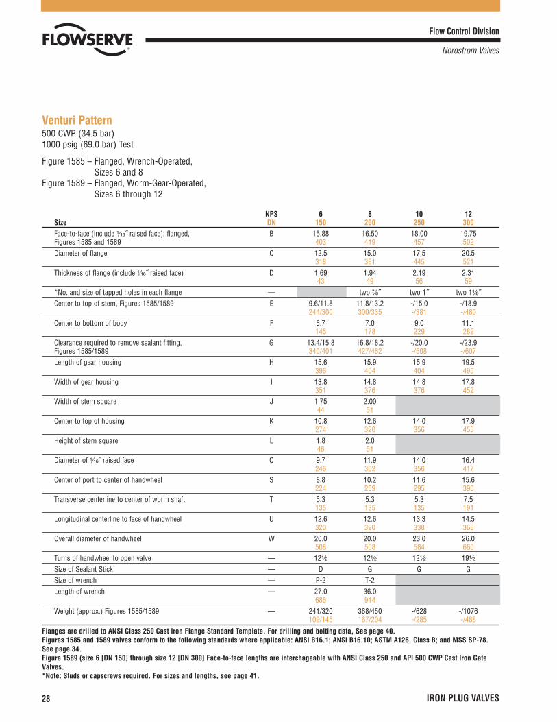
Venturi Pattern500 CWP (34.5 bar)1000 psig (69.0 bar) Test
Figure 1585 – Flanged, Wrench-Operated, Sizes 6 and 8
Figure 1589 – Flanged, Worm-Gear-Operated, Sizes 6 through 12
NPS 6 8 10 12Size DN 150 200 250 300Face-to-face (include ¹�₁₆˝ raised face), flanged, B 15.88 16.50 18.00 19.75Figures 1585 and 1589 403 419 457 502Diameter of flange C 12.5 15.0 17.5 20.5
318 381 445 521Thickness of flange (include ¹�₁₆˝ raised face) D 1.69 1.94 2.19 2.31
43 49 56 59*No. and size of tapped holes in each flange — two ⁷�₈˝ two 1˝ two 1¹�₈˝Center to top of stem, Figures 1585/1589 E 9.6/11.8 11.8/13.2 -/15.0 -/18.9
244/300 300/335 -/381 -/480Center to bottom of body F 5.7 7.0 9.0 11.1
145 178 229 282Clearance required to remove sealant fitting, G 13.4/15.8 16.8/18.2 -/20.0 -/23.9Figures 1585/1589 340/401 427/462 -/508 -/607Length of gear housing H 15.6 15.9 15.9 19.5
396 404 404 495Width of gear housing I 13.8 14.8 14.8 17.8
351 376 376 452Width of stem square J 1.75 2.00
44 51Center to top of housing K 10.8 12.6 14.0 17.9
274 320 356 455Height of stem square L 1.8 2.0
46 51Diameter of ¹�₁₆˝ raised face O 9.7 11.9 14.0 16.4
246 302 356 417Center of port to center of handwheel S 8.8 10.2 11.6 15.6
224 259 295 396Transverse centerline to center of worm shaft T 5.3 5.3 5.3 7.5
135 135 135 191Longitudinal centerline to face of handwheel U 12.6 12.6 13.3 14.5
320 320 338 368Overall diameter of handwheel W 20.0 20.0 23.0 26.0
508 508 584 660Turns of handwheel to open valve — 12¹�₂ 12¹�₂ 12¹�₂ 19¹�₂
Size of Sealant Stick — D G G GSize of wrench — P-2 T-2Length of wrench — 27.0 36.0
686 914Weight (approx.) Figures 1585/1589 — 241/320 368/450 -/628 -/1076
109/145 167/204 -/285 -/488
Flanges are drilled to ANSI Class 250 Cast Iron Flange Standard Template. For drilling and bolting data, See page 40.Figures 1585 and 1589 valves conform to the following standards where applicable: ANSI B16.1; ANSI B16.10; ASTM A126, Class B; and MSS SP-78.See page 34.Figure 1589 (size 6 [DN 150] through size 12 [DN 300] Face-to-face lengths are interchageable with ANSI Class 250 and API 500 CWP Cast Iron GateValves.*Note: Studs or capscrews required. For sizes and lengths, see page 41.
Flow Control Division
Nordstrom Valves
IRON PLUG VALVES 29
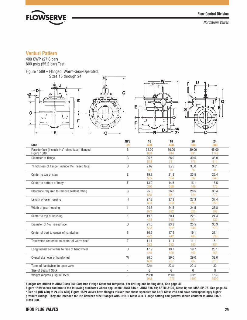
Venturi Pattern400 CWP (27.6 bar)800 psig (55.2 bar) Test
Figure 1589 – Flanged, Worm-Gear-Operated, Sizes 16 through 24
NPS 16 18 20 24Size DN 400 450 500 600Face-to-face (include ¹�₁₆˝ raised face), flanged, B 33.00 36.00 39.00 45.00Figure 1589 838 914 991 1143Diameter of flange C 25.5 28.0 30.5 36.0
648 711 775 914*Thickness of flange (include ¹�₁₆˝ raised face) D 2.69 2.75 3.00 3.31
68 70 76 84Center to top of stem E 19.9 21.8 23.5 25.4
505 554 597 645Center to bottom of body F 13.0 14.5 16.1 18.5
330 368 409 470Clearance required to remove sealant fitting G 25.0 26.8 28.5 30.4
635 681 724 772Length of gear housing H 27.3 27.3 27.3 37.4
693 693 693 950Width of gear housing I 24.5 24.5 24.5 35.8
622 622 622 909Center to top of housing K 19.6 20.4 22.1 24.4
498 518 561 620Diameter of ¹�₁₆˝ raised face O 21.0 23.3 25.5 30.3
533 592 648 770Center of port to center of handwheel S 16.6 17.4 19.1 21.1
422 442 485 536Transverse centerline to center of worm shaft T 11.1 11.1 11.1 15.1
282 282 282 384Longitudinal centerline to face of handwheel U 17.9 19.7 19.7 26.1
455 500 500 663Overall diameter of handwheel W 26.0 29.0 29.0 32.0
660 737 737 813Turns of handwheel to open valve - 22¹�₂ 22¹�₂ 22¹�₂ 32Size of Sealant Stick - G G G GWeight (approx.) Figure 1589 - 2080 2800 3525 5730
943 1270 1599 2599
Flanges are drilled to ANSI Class 250 Cast Iron Flange Standard Template. For drilling and bolting data, See page 40.Figure 1589 valves conform to the following standards where applicable: ANSI B16.1; ANSI B16.10; ASTM A126, Class B; and MSS SP-78. See page 34.*Size 16 (DN 400) to 24 (DN 600) Figure 1589 valves have flanges thicker than those specified for ANSI Class 250 and have correspondingly higherpressure ratings. They are intended for use between steel flanges ANSI B16.5 Class 300. Flange bolting and gaskets should conform to ANSI B16.5Class 300.

Flow Control Division
Nordstrom Valves
30 IRON PLUG VALVES
Regular Pattern800 CWP (55.2 bar)1600 psig (110.3 bar) Test
Figure 824 – Threaded, Wrench-Operated, Sizes ³�₄ through 3Figure 825 – Flanged, Wrench-Operated, Sizes 2 through 4
Nordstrom Screwed Gland-Type Iron Plug Valves
NPS ³�₄ 1 2 3 4Size DN 20 25 50 80 100End-to-end, threaded, Figure 824 A 3.75 4.88 8.13 10.00
95 124 206 254Face-to-face, flanged (include ¹�₄˝ raised face), B 11.50 14.00 17.00Figure 825 292 356 432Diameter of flange C 6.5 8.3 10.8
165 211 274Thickness of flange (not include ¹�₄˝ raised face) D 1.25 1.50 1.88
32 38 48Center to top of stem E 4.3 4.7 6.5 8.1 8.6
109 119 165 206 218Center to bottom of body F 1.8 2.1 3.2 4.5 5.0
46 53 81 114 127Clearance required to remove sealant fitting G 6.9 7.4 9.2 10.7 11.2
175 188 234 272 284Width of stem flats J .81 .88 1.12 1.38 1.38
21 22 28 35 35Diameter of stem K 1.09 1.22 1.59 1.97 1.97
28 31 40 50 50Height of stem flats L .8 .9 1.1 1.3 1.3
20 23 28 33 33Extreme width of body, Figure 824 M 3.2 3.3 6.3 7.8
81 84 160 198Diameter of ¹�₄˝ raised face O 3.6 5.0 6.2
91 127 157Size of wrench — SN-1 E-9 K-9 M-9 M-9Length of wrench — 7.0 7.0 14.0 34.0 34.0
178 178 356 864 864Size of Sealant Stick — B B B B BWeight (approx.) Figure 824 — 7 10 38 82
3 5 17 37Weight (approx.) Figure 825 — 56 118 178
25 54 81
Flanges are drilled to American Hydraulic Class 800 Cast Iron Flange Standard Template. For drilling and bolting data, See page 40.Figures 824 and 825 valves conform to the following standards where applicable: ANSI B1.20.1; ANSI B16.1; API 5B; ASTM A126, Class B; and MSS SP-78. See page 34.Flange dimensions and drilling are the same as for ANSI Class 600 steel flanges, except for flange thickness.
Flow Control Division
Nordstrom Valves
IRON PLUG VALVES 31
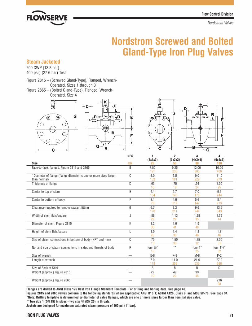
Steam Jacketed200 CWP (13.8 bar)400 psig (27.6 bar) Test
Figure 2815 – (Screwed Gland-Type), Flanged, Wrench-Operated, Sizes 1 through 3
Figure 2865 – (Bolted Gland-Type), Flanged, Wrench-Operated, Size 4
Nordstrom Screwed and Bolted Gland-Type Iron Plug Valves
NPS 1 2 3 4(2x1x2) (3x2x3) (4x3x4) (6x4x6)
Size DN 25 50 80 100Face-to-face, flanged, Figure 2815 and 2865 B 7.50 9.25 12.00 16.00
191 235 305 406*Diameter of flange (flange diameter is one or more sizes larger C 6.0 7.5 9.0 11.0than normal) 152 191 229 279Thickness of flange D .63 .75 .94 1.00
16 19 24 25Center to top of stem E 4.1 5.7 7.0 9.6
104 145 178 244Center to bottom of body F 3.1 4.6 5.6 8.4
79 117 142 213Clearance required to remove sealant fitting G 6.7 8.3 9.6 13.5
170 211 244 343Width of stem flats/square J .88 1.13 1.38 1.75
22 29 35 44Diameter of stem, Figure 2815 K 1.2 1.6 1.9
30 41 48Height of stem flats/square L 1.0 1.4 1.8 1.8
25 36 46 46Size of steam connections in bottom of body (NPT and mm) Q .75 1.50 1.25 2.00
19 38 32 51No. and size of steam connections in sides and throats of body R four ¹�₂˝ ** four 1˝ four 1¹�₄˝
15 25 32Size of wrench — E-8 K-8 M-8 P-2Length of wrench — 7.0 14.0 21.0 27.0
178 356 533 686Size of Sealant Stick — B B B DWeight (approx.) Figure 2815 — 22 49 99
10 22 45Weight (approx.) Figure 2865 — 216
98
Flanges are drilled to ANSI Class 125 Cast Iron Flange Standard Template. For drilling and bolting data, See page 40.Figures 2815 and 2865 valves conform to the following standards where applicable: ANSI B16.1; ASTM A126, Class B; and MSS SP-78. See page 34.*Note: Drilling template is determined by diameter of valve flanges, which are one or more sizes larger than nominal size valve.**Two size 1 (DN 25) in sides - two size ³�₄ (DN 20) in throats.Jackets are designed for maximum saturated steam pressure of 160 psi (11 bar).

Flow Control Division
Nordstrom Valves
32 IRON PLUG VALVES
Style 38 Compression Ends for Steel Pipe200 CWP (13.8 bar)400 psig (27.6 bar) Test
Figure 24191 – Wrench-Operated, Six Bolt End, Size 6
Nordstrom Bolted Gland-Type Iron Plug Valves
NPS 6Size DN 150
End-to-end, Figure 24191 A 18.00457
Center to top of stem E 9.6244
Center to bottom of body F 5.4137
Clearance required to remove sealant fitting G 13.7348
Width of stem square J 1.7544
Height of stem square L 1.846
Extreme width of body M 10.4264
Depth of hub bore N 2.564
Minimum inside diameter of hub O 6.7170
Size of wrench — P-2
Length of wrench — 27.0686
Size of Sealant Stick — D
Weight (approx.) Figure 24191 — 16374
Body and plug material conform to ASTM A126, Class B and MSS SP-78. See page 34.
Flow Control Division
Nordstrom Valves
IRON PLUG VALVES 33
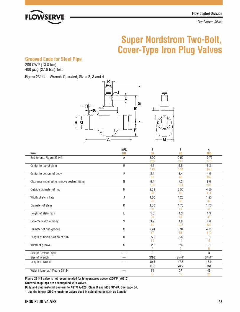
Grooved Ends for Steel Pipe200 CWP (13.8 bar)400 psig (27.6 bar) Test
Figure 23144 – Wrench-Operated, Sizes 2, 3 and 4
Super Nordstrom Two-Bolt, Cover-Type Iron Plug Valves
NPS 2 3 4Size DN 50 80 100End-to-end, Figure 23144 A 8.00 9.50 10.75
203 241 273Center to top of stem E 4.7 5.6 6.3
119 142 160Center to bottom of body F 2.4 3.4 4.0
61 86 102Clearance required to remove sealant fitting G 6.4 7.2 8.0
163 183 203Outside diameter of hub H 2.38 3.50 4.50
60 89 114Width of stem flats J 1.00 1.25 1.25
25 32 32Diameter of stem K 1.38 1.75 1.75
35 44 44Height of stem flats L 1.0 1.3 1.3
25 33 33Extreme width of body M 3.2 4.0 4.8
81 102 122Diameter of hub groove Q 2.24 3.34 4.33
57 85 110Length of finish portion of hub R .56 .56 .61
14 14 15Width of groove S .26 .26 .31
7 7 8Size of Sealant Stick — B B BSize of wrench — SN-2 SN-4* SN-4*Length of wrench — 10.5 17.5 15.0
267 445 381Weight (approx.) Figure 23144 — 14 27 46
6 12 21Figure 23144 valve is not recommended for temperatures above +200°F (+93°C).Grooved couplings are not supplied with valves.Body and plug material conform to ASTM A-126, Class B and MSS SP-78. See page 34.* Use the longer SN-3 wrench for valves used in cold climates such as Canada.
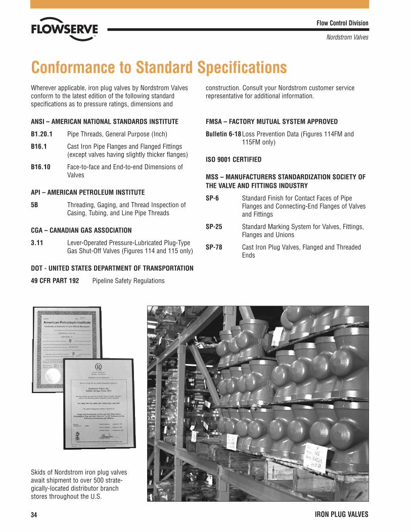
Wherever applicable, iron plug valves by Nordstrom Valvesconform to the latest edition of the following standardspecifications as to pressure ratings, dimensions and
construction. Consult your Nordstrom customer servicerepresentative for additional information.
Flow Control Division
Nordstrom Valves
34 IRON PLUG VALVES
Conformance to Standard Specifications
ANSI – AMERICAN NATIONAL STANDARDS INSTITUTE
B1.20.1 Pipe Threads, General Purpose (Inch)
B16.1 Cast Iron Pipe Flanges and Flanged Fittings(except valves having slightly thicker flanges)
B16.10 Face-to-face and End-to-end Dimensions ofValves
API – AMERICAN PETROLEUM INSTITUTE
5B Threading, Gaging, and Thread Inspection ofCasing, Tubing, and Line Pipe Threads
CGA – CANADIAN GAS ASSOCIATION
3.11 Lever-Operated Pressure-Lubricated Plug-TypeGas Shut-Off Valves (Figures 114 and 115 only)
DOT - UNITED STATES DEPARTMENT OF TRANSPORTATION
49 CFR PART 192 Pipeline Safety Regulations
FMSA – FACTORY MUTUAL SYSTEM APPROVED
Bulletin 6-18 Loss Prevention Data (Figures 114FM and115FM only)
ISO 9001 CERTIFIED
MSS – MANUFACTURERS STANDARDIZATION SOCIETY OFTHE VALVE AND FITTINGS INDUSTRY
SP-6 Standard Finish for Contact Faces of PipeFlanges and Connecting-End Flanges of Valvesand Fittings
SP-25 Standard Marking System for Valves, Fittings,Flanges and Unions
SP-78 Cast Iron Plug Valves, Flanged and ThreadedEnds
Skids of Nordstrom iron plug valvesawait shipment to over 500 strate-gically-located distributor branchstores throughout the U.S.
Flow Control Division
Nordstrom Valves
IRON PLUG VALVES 35
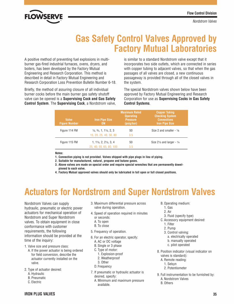
A positive method of preventing fuel explosions in multi-burner gas-fired industrial furnaces, ovens, dryers, andboilers, has been developed by the Factory MutualEngineering and Research Corporation. This method isdescribed in detail in Factory Mutual Engineering andResearch Corporation Loss Prevention Bulletin Number 6-18.
Briefly, the method of assuring closure of all individualburner cocks before the main burner gas safety shutoffvalve can be opened is a Supervising Cock and Gas SafetyControl System. The Supervising Cock, a Nordstrom valve,
is similar to a standard Nordstrom valve except that itincorporates two side outlets, which are connected in serieswith copper tubing to adjacent valves, so that when the gaspassages of all valves are closed, a new continuouspassageway is provided through all of the closed valves inthe system.
The special Nordstrom valves shown below have beenapproved by Factory Mutual Engineering and ResearchCorporation for use as Supervising Cocks in Gas SafetyControl Systems.
Gas Safety Control Valves Approved by Factory Mutual Laboratories
Maximum Rated Copper TubingOperating Checking System
Valve Iron Pipe Size Pressure ConnectionsFigure Number DN (psig/bar) Iron Pipe Size
Figure 114 FM ¹�₂, ³�₄, 1, 1¹�₂, 2, 3 50 Size 2 and smaller - ¹�₈15, 20, 25, 40, 50, 80 3.5
Figure 115 FM 1, 1¹�₂, 2, 2¹�₂, 3, 4 50 Size 2¹�₂ and larger - ¹�₄25, 40, 50, 65, 80, 100 3.5
Notes:1. Connection piping is not provided. Valves shipped with pipe plugs in lieu of piping.2. Suitable for manufactured, natural, propane and butane gases.3. Above valves are made on special order and require special wrenches that are permanently dowel-
pinned to each valve.4. Factory Mutual approved valves should only be lubricated in full open or full closed positions.
Nordstrom Valves can supplyhydraulic, pneumatic or electric poweractuators for mechanical operation ofNordstrom and Super Nordstromvalves. To obtain equipment in closeconformance with customerrequirements, the followinginformation should be provided at thetime of the inquiry:1. Valve size and pressure class:
A. If the power actuator is being orderedfor field conversion, describe theactuator currently installed on thevalve.
2. Type of actuator desired:A. HydraulicB. PneumaticC. Electric
3. Maximum differential pressure acrossvalve during operation.
4. Speed of operation required in minutesor seconds:A. To openB. To close
5. Frequency of operation.
6. For an electric operator, specify:A. AC or DC voltageB. Single or 3 phaseC. Type of motor:
1. Explosion-proof2. Weatherproof3. Other
D. Frequency
7. If pneumatic or hydraulic actuator isdesired, specify:A. Minimum and maximum pressure
available.
B. Operating medium:1. Gas2. Air3. Fluid (specify type)
C. Accessory equipment desired:1. Filter2. Pump3. Control valving:
a. electrically operatedb. manually operatedc. pilot operated
8. Position indicator (visual indicator onvalves is standard):A. Remote reading:
1. Selsyn2. Potentiometer
9. Full instrumentation to be furnished by:A. Nordstrom ValvesB. Others
Actuators for Nordstrom and Super Nordstrom Valves
Flow Control Division
Nordstrom Valves
36 IRON PLUG VALVES
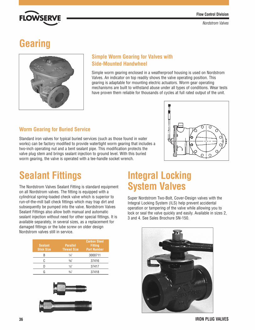
Gearing
Standard iron valves for typical buried services (such as those found in waterworks) can be factory modified to provide watertight worm gearing that includes atwo-inch operating nut and a bent sealant pipe. This modification protects thevalve plug stem and brings sealant injection to ground level. With this buriedworm gearing, the valve is operated with a tee-handle socket wrench.
Worm Gearing for Buried Service
Simple worm gearing enclosed in a weatherproof housing is used on NordstromValves. An indicator on top readily shows the valve operating position. Thisgearing is adaptable for mounting electric actuators. Worm gear operatingmechanisms are built to withstand abuse under all types of conditions. Wear testshave proven them reliable for thousands of cycles at full rated output of the unit.
Simple Worm Gearing for Valves withSide-Mounted Handwheel
The Nordstrom Valves Sealant Fitting is standard equipmenton all Nordstrom valves. The fitting is equipped with acylindrical spring-loaded check valve which is superior torun-of-the-mill ball check fittings which may trap dirt andsubsequently be pumped into the valve. Nordstrom ValvesSealant Fittings also allow both manual and automaticsealant injection without need for other special fittings. It isavailable separately, in several sizes, as a replacement fordamaged fittings or the lube screw on older designNordstrom valves still in service.
Sealant Fittings
Super Nordstrom Two-Bolt, Cover-Design valves with theIntegral Locking System (ILS) help prevent accidentaloperation or tampering of the valve while allowing you tolock or seal the valve quickly and easily. Available in sizes 2,3 and 4. See Sales Brochure SN-150.
Integral Locking System Valves
Carbon SteelSealant Parallel Fitting
Stick Size Thread Size Part Number
B ¹�₄" 3000711
C ³�₈" 37416
D ¹�₂" 37417
G ³�₄" 37418
Flow Control Division
Nordstrom Valves
IRON PLUG VALVES 37
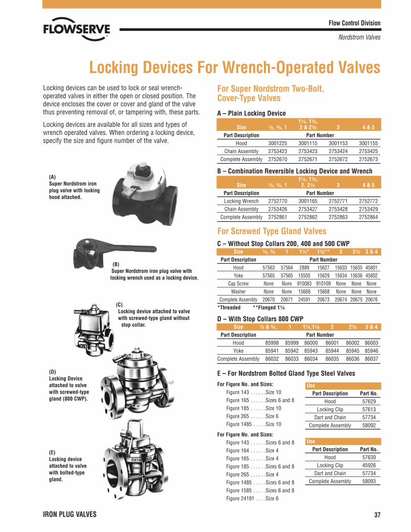
Locking devices can be used to lock or seal wrench-operated valves in either the open or closed position. Thedevice encloses the cover or cover and gland of the valvethus preventing removal of, or tampering with, these parts.
Locking devices are available for all sizes and types ofwrench operated valves. When ordering a locking device,specify the size and figure number of the valve.
(A)Super Nordstrom ironplug valve with lockinghood attached.
(B)Super Nordstrom iron plug valve withlocking wrench used as a locking device.
(C)Locking device attached to valvewith screwed-type gland without
stop collar.
(D)Locking Deviceattached to valvewith screwed-typegland (800 CWP).
(E)Locking deviceattached to valvewith bolted-typegland.
Locking Devices For Wrench-Operated ValvesFor Super Nordstrom Two-Bolt, Cover-Type Valves
A – Plain Locking Device1¹�₄, 1¹�₂,
Size ¹�₂, ³�₄, 1 2 & 2¹�₂ 3 4 & 5Part Description Part Number
Hood 3001225 3001115 3001153 3001155Chain Assembly 2753423 2753423 2753424 2753425
Complete Assembly 2752670 2752671 2752672 2752673
B – Combination Reversible Locking Device and Wrench1¹�₄, 1¹�₂,
Size ¹�₂, ³�₄, 1 2, 2¹�₂ 3 4 & 5Part Description Part NumberLocking Wrench 2752770 3001165 2752771 2752772Chain Assembly 2753426 2753427 2753428 2753429
Complete Assembly 2752861 2752862 2752863 2752864
For Screwed Type Gland ValvesC – Without Stop Collars 200, 400 and 500 CWP
Size ¹�₂, ³�₄ 1 1¹�₄* 1¹�₂** 2 2¹�₂ 3 & 4Part Description Part Number
Hood 57563 57564 2889 15627 15633 15635 45801Yoke 57565 57565 15505 15629 15634 15636 45802
Cap Screw None None 910083 910109 None None NoneWasher None None 15668 15668 None None None
Complete Assembly 20670 20671 24591 20673 20674 20675 20676*Threaded **Flanged 1¹�₄
D – With Stop Collars 800 CWPSize ¹�₂ & ³�₄, 1 1¹�₄,1¹�₂ 2 2¹�₂ 3 & 4
Part Description Part NumberHood 85998 85999 86000 86001 86002 86003Yoke 85941 85942 85943 85944 85945 85946
Complete Assembly 86032 86033 86034 86035 86036 86037
E – For Nordstrom Bolted Gland Type Steel ValvesFor Figure No. and Sizes:
Figure 143 . . . . . .Size 10Figure 165 . . . . . .Sizes 6 and 8Figure 185 . . . . . .Size 10Figure 265 . . . . . .Size 6Figure 1485 . . . . .Size 10
For Figure No. and Sizes:Figure 143 . . . . . .Sizes 6 and 8Figure 164 . . . . . .Size 4Figure 165 . . . . . .Size 4Figure 185 . . . . . .Sizes 6 and 8Figure 265 . . . . . .Size 4Figure 1485 . . . . .Sizes 6 and 8Figure 1585 . . . . .Sizes 6 and 8Figure 24191 . . . .Size 6
UsePart Description Part No.
Hood 57629Locking Clip 57613
Dart and Chain 57734Complete Assembly 58092
UsePart Description Part No.
Hood 57630Locking Clip 45926
Dart and Chain 57734Complete Assembly 58093
Flow Control Division
Nordstrom Valves
38
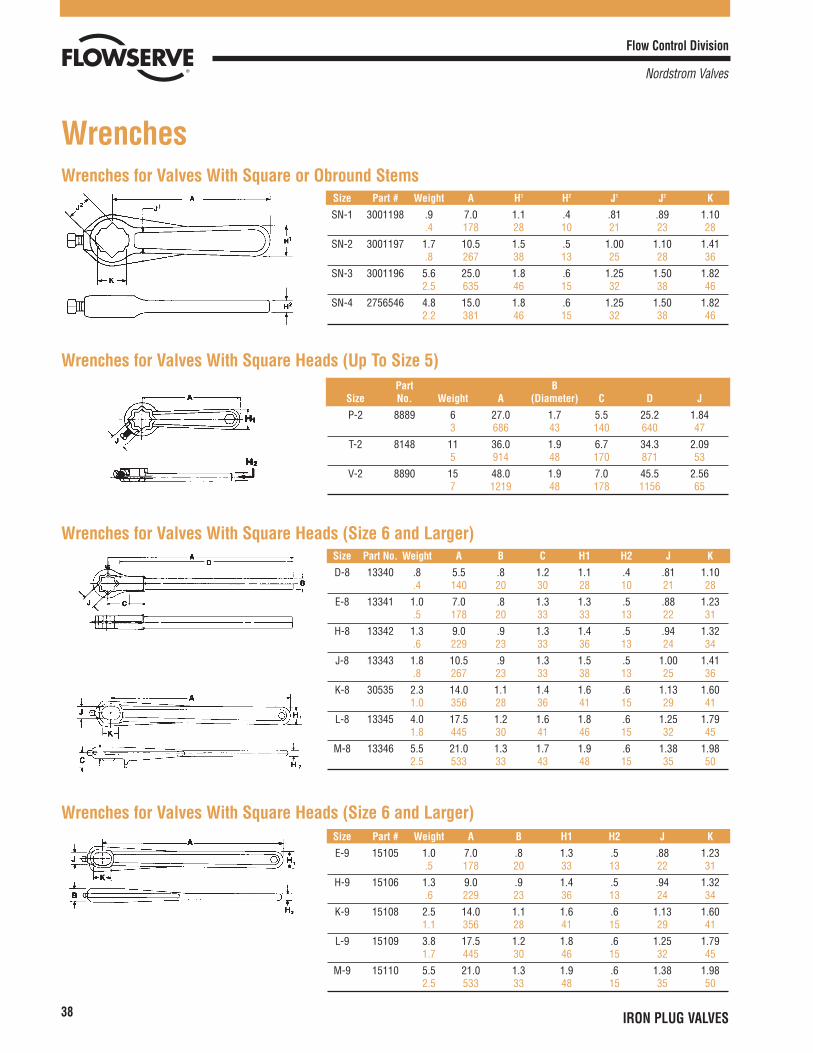
WrenchesWrenches for Valves With Square or Obround Stems
Wrenches for Valves With Square Heads (Up To Size 5)
Wrenches for Valves With Square Heads (Size 6 and Larger)
Wrenches for Valves With Square Heads (Size 6 and Larger)
Size Part # Weight A H1 H2 J1 J2 K
SN-1 3001198 .9 7.0 1.1 .4 .81 .89 1.10.4 178 28 10 21 23 28
SN-2 3001197 1.7 10.5 1.5 .5 1.00 1.10 1.41.8 267 38 13 25 28 36
SN-3 3001196 5.6 25.0 1.8 .6 1.25 1.50 1.822.5 635 46 15 32 38 46
SN-4 2756546 4.8 15.0 1.8 .6 1.25 1.50 1.822.2 381 46 15 32 38 46
Part BSize No. Weight A (Diameter) C D J
P-2 8889 6 27.0 1.7 5.5 25.2 1.843 686 43 140 640 47
T-2 8148 11 36.0 1.9 6.7 34.3 2.095 914 48 170 871 53
V-2 8890 15 48.0 1.9 7.0 45.5 2.567 1219 48 178 1156 65
Size Part No. Weight A B C H1 H2 J K
D-8 13340 .8 5.5 .8 1.2 1.1 .4 .81 1.10.4 140 20 30 28 10 21 28
E-8 13341 1.0 7.0 .8 1.3 1.3 .5 .88 1.23.5 178 20 33 33 13 22 31
H-8 13342 1.3 9.0 .9 1.3 1.4 .5 .94 1.32.6 229 23 33 36 13 24 34
J-8 13343 1.8 10.5 .9 1.3 1.5 .5 1.00 1.41.8 267 23 33 38 13 25 36
K-8 30535 2.3 14.0 1.1 1.4 1.6 .6 1.13 1.601.0 356 28 36 41 15 29 41
L-8 13345 4.0 17.5 1.2 1.6 1.8 .6 1.25 1.791.8 445 30 41 46 15 32 45
M-8 13346 5.5 21.0 1.3 1.7 1.9 .6 1.38 1.982.5 533 33 43 48 15 35 50
Size Part # Weight A B H1 H2 J K
E-9 15105 1.0 7.0 .8 1.3 .5 .88 1.23.5 178 20 33 13 22 31
H-9 15106 1.3 9.0 .9 1.4 .5 .94 1.32.6 229 23 36 13 24 34
K-9 15108 2.5 14.0 1.1 1.6 .6 1.13 1.601.1 356 28 41 15 29 41
L-9 15109 3.8 17.5 1.2 1.8 .6 1.25 1.791.7 445 30 46 15 32 45
M-9 15110 5.5 21.0 1.3 1.9 .6 1.38 1.982.5 533 33 48 15 35 50
IRON PLUG VALVES
Flow Control Division
Nordstrom Valves
IRON PLUG VALVES 39
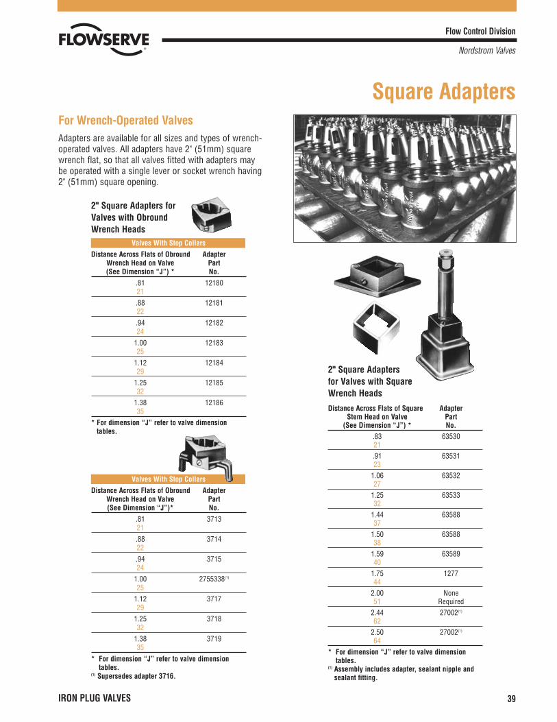
For Wrench-Operated ValvesAdapters are available for all sizes and types of wrench-operated valves. All adapters have 2" (51mm) squarewrench flat, so that all valves fitted with adapters may be operated with a single lever or socket wrench having 2" (51mm) square opening.
2" Square Adapters forValves with ObroundWrench Heads
Valves With Stop CollarsDistance Across Flats of Obround Adapter
Wrench Head on Valve Part(See Dimension “J”) * No.
.81 1218021.88 1218122.94 1218224
1.00 1218325
1.12 1218429
1.25 1218532
1.38 1218635
* For dimension “J” refer to valve dimensiontables.
Valves With Stop CollarsDistance Across Flats of Obround Adapter
Wrench Head on Valve Part(See Dimension “J”)* No.
.81 371321.88 371422.94 371524
1.00 2755338(1)
251.12 371729
1.25 371832
1.38 371935
* For dimension “J” refer to valve dimensiontables.
(1) Supersedes adapter 3716.
2" Square Adapters for Valves with Square Wrench Heads
Distance Across Flats of Square AdapterStem Head on Valve Part
(See Dimension “J”) * No..83 6353021.91 6353123
1.06 6353227
1.25 6353332
1.44 6358837
1.50 6358838
1.59 6358940
1.75 127744
2.00 None51 Required
2.44 27002(1)
622.50 27002(1)
64* For dimension “J” refer to valve dimension
tables.(1) Assembly includes adapter, sealant nipple and
sealant fitting.
Square Adapters
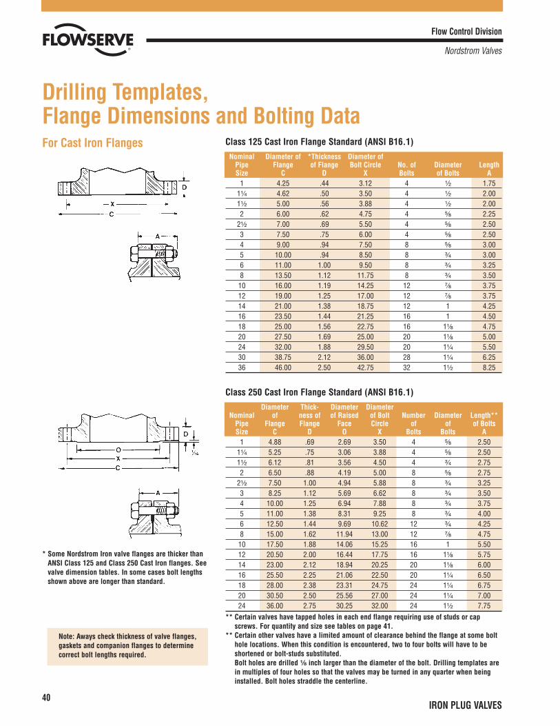
For Cast Iron Flanges
* Some Nordstrom Iron valve flanges are thicker thanANSI Class 125 and Class 250 Cast Iron flanges. Seevalve dimension tables. In some cases bolt lengthsshown above are longer than standard.
Note: Aways check thickness of valve flanges,gaskets and companion flanges to determinecorrect bolt lengths required.
Flow Control Division
Nordstrom Valves
40IRON PLUG VALVES
Drilling Templates, Flange Dimensions and Bolting Data
Class 125 Cast Iron Flange Standard (ANSI B16.1)Nominal Diameter of *Thickness Diameter of
Pipe Flange of Flange Bolt Circle No. of Diameter LengthSize C D X Bolts of Bolts A
1 4.25 .44 3.12 4 ¹�₂ 1.751¹�₄ 4.62 .50 3.50 4 ¹�₂ 2.001¹�₂ 5.00 .56 3.88 4 ¹�₂ 2.002 6.00 .62 4.75 4 ⁵�₈ 2.25
2¹�₂ 7.00 .69 5.50 4 ⁵�₈ 2.503 7.50 .75 6.00 4 ⁵�₈ 2.504 9.00 .94 7.50 8 ⁵�₈ 3.005 10.00 .94 8.50 8 ³�₄ 3.006 11.00 1.00 9.50 8 ³�₄ 3.258 13.50 1.12 11.75 8 ³�₄ 3.5010 16.00 1.19 14.25 12 ⁷�₈ 3.7512 19.00 1.25 17.00 12 ⁷�₈ 3.7514 21.00 1.38 18.75 12 1 4.2516 23.50 1.44 21.25 16 1 4.5018 25.00 1.56 22.75 16 1¹�₈ 4.7520 27.50 1.69 25.00 20 1¹�₈ 5.0024 32.00 1.88 29.50 20 1¹�₄ 5.5030 38.75 2.12 36.00 28 1¹�₄ 6.2536 46.00 2.50 42.75 32 1¹�₂ 8.25
Class 250 Cast Iron Flange Standard (ANSI B16.1)Diameter Thick- Diameter Diameter
Nominal of ness of of Raised of Bolt Number Diameter Length**Pipe Flange Flange Face Circle of of of BoltsSize C D O X Bolts Bolts A
1 4.88 .69 2.69 3.50 4 ⁵�₈ 2.501¹�₄ 5.25 .75 3.06 3.88 4 ⁵�₈ 2.501¹�₂ 6.12 .81 3.56 4.50 4 ³�₄ 2.752 6.50 .88 4.19 5.00 8 ⁵�₈ 2.75
2¹�₂ 7.50 1.00 4.94 5.88 8 ³�₄ 3.253 8.25 1.12 5.69 6.62 8 ³�₄ 3.504 10.00 1.25 6.94 7.88 8 ³�₄ 3.755 11.00 1.38 8.31 9.25 8 ³�₄ 4.006 12.50 1.44 9.69 10.62 12 ³�₄ 4.258 15.00 1.62 11.94 13.00 12 ⁷�₈ 4.7510 17.50 1.88 14.06 15.25 16 1 5.5012 20.50 2.00 16.44 17.75 16 1¹�₈ 5.7514 23.00 2.12 18.94 20.25 20 1¹�₈ 6.0016 25.50 2.25 21.06 22.50 20 1¹�₄ 6.5018 28.00 2.38 23.31 24.75 24 1¹�₄ 6.7520 30.50 2.50 25.56 27.00 24 1¹�₄ 7.0024 36.00 2.75 30.25 32.00 24 1¹�₂ 7.75
** Certain valves have tapped holes in each end flange requiring use of studs or capscrews. For quantity and size see tables on page 41.
** Certain other valves have a limited amount of clearance behind the flange at some bolthole locations. When this condition is encountered, two to four bolts will have to beshortened or bolt-studs substituted.Bolt holes are drilled ¹�₈ inch larger than the diameter of the bolt. Drilling templates arein multiples of four holes so that the valves may be turned in any quarter when beinginstalled. Bolt holes straddle the centerline.
Flow Control Division
Nordstrom Valves
41IRON PLUG VALVES
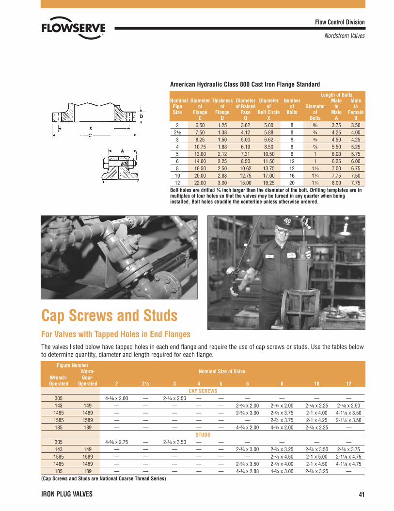
American Hydraulic Class 800 Cast Iron Flange StandardLength of Bolts
Nominal Diameter Thickness Diameter Diameter Number Male MalePipe of of of Raised of of Diameter to toSize Flange Flange Face Bolt Circle Bolts of Male Female
C D O X Bolts A B2 6.50 1.25 3.62 5.00 8 ⁵�₈ 3.75 3.50
2¹�₂ 7.50 1.38 4.12 5.88 8 ³�₄ 4.25 4.003 8.25 1.50 5.00 6.62 8 ³�₄ 4.50 4.254 10.75 1.88 6.19 8.50 8 ⁷�₈ 5.50 5.255 13.00 2.12 7.31 10.50 8 1 6.00 5.756 14.00 2.25 8.50 11.50 12 1 6.25 6.008 16.50 2.50 10.62 13.75 12 1¹�₈ 7.00 6.7510 20.00 2.88 12.75 17.00 16 1¹�₄ 7.75 7.5012 22.00 3.00 15.00 19.25 20 1¹�₄ 8.00 7.75
Bolt holes are drilled ¹�₈ inch larger than the diameter of the bolt. Drilling templates are inmultiples of four holes so that the valves may be turned in any quarter when beinginstalled. Bolt holes straddle the centerline unless otherwise ordered.
Cap Screws and StudsFor Valves with Tapped Holes in End FlangesThe valves listed below have tapped holes in each end flange and require the use of cap screws or studs. Use the tables belowto determine quantity, diameter and length required for each flange.
Figure NumberWorm- Nominal Size of Valve
Wrench- Gear-Operated Operated 2 2¹�₂ 3 4 5 6 8 10 12
CAP SCREWS305 4-⁵�₈ x 2.00 — 2-³�₄ x 2.50 — — — — — —143 149 — — — — — 2-³�₄ x 2.00 2-³�₄ x 2.00 2-⁷�₈ x 2.25 2-⁷�₈ x 2.501485 1489 — — — — — 2-³�₄ x 3.00 2-⁷�₈ x 3.75 2-1 x 4.00 4-1¹�₈ x 3.501585 1589 — — — — — — 2-⁷�₈ x 3.75 2-1 x 4.25 2-1¹�₈ x 3.50185 189 — — — — — 4-³�₄ x 2.00 4-³�₄ x 2.00 2-⁷�₈ x 2.25 —
STUDS305 4-⁵�₈ x 2.75 — 2-³�₄ x 3.50 — — — — — —143 149 — — — — — 2-³�₄ x 3.00 2-³�₄ x 3.25 2-⁷�₈ x 3.50 2-⁷�₈ x 3.751585 1589 — — — — — — 2-⁷�₈ x 4.50 2-1 x 5.00 2-1¹�₈ x 4.751485 1489 — — — — — 2-³�₄ x 3.50 2-⁷�₈ x 4.00 2-1 x 4.50 4-1¹�₈ x 4.75185 189 — — — — — 4-³�₄ x 2.88 4-³�₄ x 3.00 2-⁷�₈ x 3.25 —
(Cap Screws and Studs are National Coarse Thread Series)
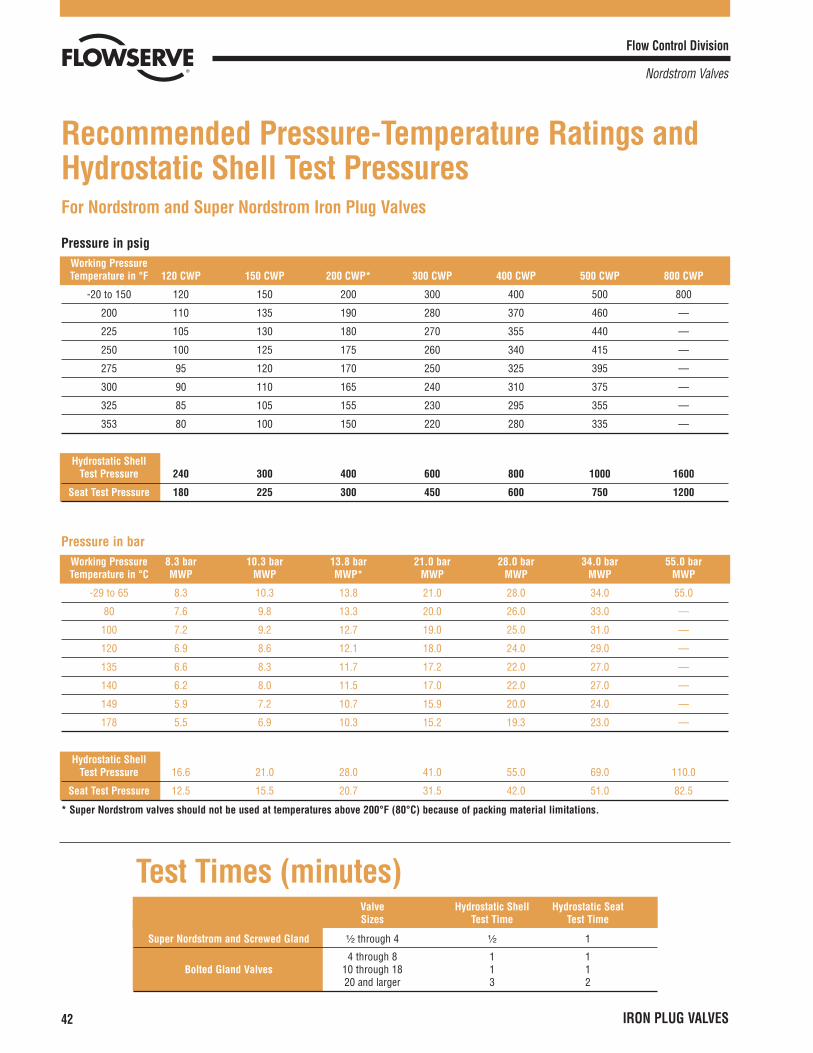
For Nordstrom and Super Nordstrom Iron Plug Valves
Pressure in psigWorking PressureTemperature in °F 120 CWP 150 CWP 200 CWP* 300 CWP 400 CWP 500 CWP 800 CWP
-20 to 150 120 150 200 300 400 500 800
200 110 135 190 280 370 460 —
225 105 130 180 270 355 440 —
250 100 125 175 260 340 415 —
275 95 120 170 250 325 395 —
300 90 110 165 240 310 375 —
325 85 105 155 230 295 355 —
353 80 100 150 220 280 335 —
Hydrostatic ShellTest Pressure 240 300 400 600 800 1000 1600
Seat Test Pressure 180 225 300 450 600 750 1200
Pressure in barWorking Pressure 8.3 bar 10.3 bar 13.8 bar 21.0 bar 28.0 bar 34.0 bar 55.0 barTemperature in °C MWP MWP MWP* MWP MWP MWP MWP
-29 to 65 8.3 10.3 13.8 21.0 28.0 34.0 55.0
80 7.6 9.8 13.3 20.0 26.0 33.0 —
100 7.2 9.2 12.7 19.0 25.0 31.0 —
120 6.9 8.6 12.1 18.0 24.0 29.0 —
135 6.6 8.3 11.7 17.2 22.0 27.0 —
140 6.2 8.0 11.5 17.0 22.0 27.0 —
149 5.9 7.2 10.7 15.9 20.0 24.0 —
178 5.5 6.9 10.3 15.2 19.3 23.0 —
Hydrostatic ShellTest Pressure 16.6 21.0 28.0 41.0 55.0 69.0 110.0
Seat Test Pressure 12.5 15.5 20.7 31.5 42.0 51.0 82.5
* Super Nordstrom valves should not be used at temperatures above 200°F (80°C) because of packing material limitations.
Flow Control Division
Nordstrom Valves
42 IRON PLUG VALVES
Recommended Pressure-Temperature Ratings andHydrostatic Shell Test Pressures
Test Times (minutes)Valve Hydrostatic Shell Hydrostatic SeatSizes Test Time Test Time
Super Nordstrom and Screwed Gland ¹�₂ through 4 ¹�₂ 1
4 through 8 1 1Bolted Gland Valves 10 through 18 1 1
20 and larger 3 2
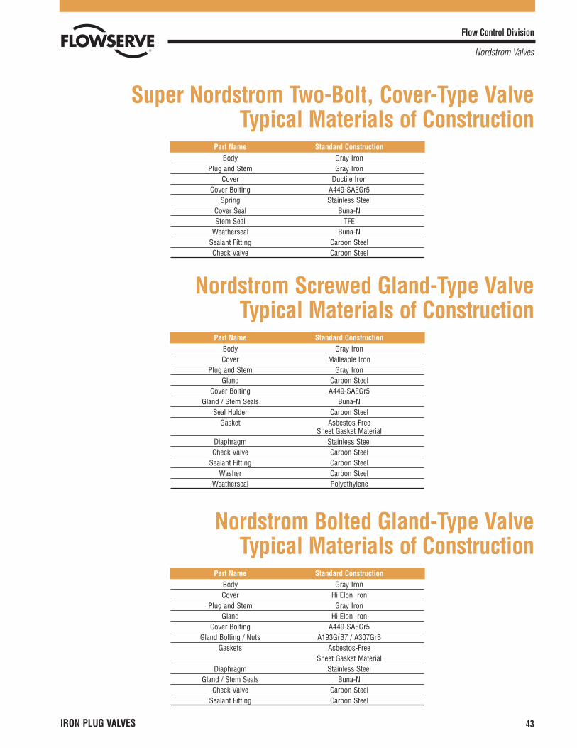
Flow Control Division
Nordstrom Valves
IRON PLUG VALVES 43
Super Nordstrom Two-Bolt, Cover-Type Valve Typical Materials of Construction
Part Name Standard ConstructionBody Gray Iron
Plug and Stem Gray IronCover Ductile Iron
Cover Bolting A449-SAEGr5Spring Stainless Steel
Cover Seal Buna-NStem Seal TFE
Weatherseal Buna-NSealant Fitting Carbon SteelCheck Valve Carbon Steel
Nordstrom Screwed Gland-Type Valve Typical Materials of Construction
Part Name Standard ConstructionBody Gray IronCover Malleable Iron
Plug and Stem Gray IronGland Carbon Steel
Cover Bolting A449-SAEGr5Gland / Stem Seals Buna-N
Seal Holder Carbon SteelGasket Asbestos-Free
Sheet Gasket MaterialDiaphragm Stainless SteelCheck Valve Carbon Steel
Sealant Fitting Carbon SteelWasher Carbon Steel
Weatherseal Polyethylene
Nordstrom Bolted Gland-Type Valve Typical Materials of Construction
Part Name Standard ConstructionBody Gray IronCover Hi Elon Iron
Plug and Stem Gray IronGland Hi Elon Iron
Cover Bolting A449-SAEGr5Gland Bolting / Nuts A193GrB7 / A307GrB
Gaskets Asbestos-FreeSheet Gasket Material
Diaphragm Stainless SteelGland / Stem Seals Buna-N
Check Valve Carbon SteelSealant Fitting Carbon Steel
Nordstrom Valves
Flow Control Division
Nordstrom Valves
Flowserve Corporation has established industry leadership in the design and manufacture of its products. When properly selected, this Flowserve product is designed to perform its intended function safely during its useful life.However, the purchaser or user of Flowserve products should be aware that Flowserve products might be used in numerous applications under a wide variety of industrial service conditions. Although Flowserve can (and often does)provide general guidelines, it cannot provide specific data and warnings for all possible applications. The purchaser/user must therefore assume the ultimate responsibility for the proper sizing and selection, installation, operation, andmaintenance of Flowserve products. The purchaser/user should read and understand the Installation Operation Maintenance (IOM) instructions included with the product, and train its employees and contractors in the safe use ofFlowserve products in connection with the specific application.
While the information and specifications contained in this literature are believed to be accurate, they are supplied for informative purposes only and should not be considered certified or as a guarantee of satisfactory results by reliancethereon. Nothing contained herein is to be construed as a warranty or guarantee, express or implied, regarding any matter with respect to this product. Because Flowserve is continually improving and upgrading its product design, thespecifications, dimensions and information contained herein are subject to change without notice. Should any question arise concerning these provisions, the purchaser/user should contact Flowserve Corporation at any one of itsworldwide operations or offices.
For more information about Flowserve Corporation, contact www.flowserve.com or call USA 1 800 225 6989.
© 2003 Flowserve Corporation, Irving, Texas, USA. Flowserve and Nordstrom Valves are registered trademarks of Flowserve Corporation. NVABR1003 (Replaces NI-100) 11/03 Printed in USA
Email: [email protected] visit www.flowserve.com
Authorized Distributors
For detailed information on these and otherNordstrom Valves products, call your customerservice representative for the name and number ofthe nearest authorized Nordstrom Valves distributor.
1511 Jefferson Street Sulphur Springs, Texas 75482USA1-800-225-6989
United States: Telephone: 903-885-4691 or 4693FAX: 903-439-3411
Latin America: Telephone: 903-439-3407 FAX: 903-439-3411
Other Countries: Telephone: 903-885-4692 FAX: 903-439-3404
Get The Nordstrom Valves Edge… • Value • Quality • Dependability
Around The World, Nordstrom Valves®
Lubricated Plug Valves Have WorkedFor Over 70 Years —
Recommended