NAVAL POSTGRADUATE SCHOOLLn
,.% Monterey, CaliforniaiLO P
S
TUTESIS
NEAR REAL TIME %*IHIF TELEMETIRY OF NEAR
SIHORE OCEANOGRAPIlIC DATA
by
Douglas L. .IcKinncy
June 1989
Thesis Advisor Steven R. Ramp
Approved for public release,&distribution unlimited. D'TIC
SELECTE' DEC 1989
89 12 14

DISLAIMEOTIc
THIS DOCUMENT IS BESTQUALITY AVAILABLE. THE COPY
FURNISHED TO DTIC CONTAINEDA SIGNIFICANT NUMBER OF
PAGES WHICH DO NOT
REPRODUCE LEGIBLY.

R FIPOR I 1)O(t \I I A I I 0\ I11M, F
t- pproved b'r public rclcas c: istribution 1,, unlimited.
f~ce m io! 7 Name of \1onitoi~ng Organization1 P' \ ~ ~35 aval Po ,tarad-u:itte School
\ \n-co CA \ M''ontrev CAX 93()43-50)
['a" No P~~c r )) : C\, IK .
I) . 'NIS,
'I~V I I- j
I 11 t r~ll\ N\- cturc-, 'r-l> tpropa''aion. loA -2 :,.t.
N I~I\ ~I I . x' aitha" lo\\ po\\'r wlOhutlptlorl atiJ ih lrVYKPc:T1Y. V0. L-1 uxI'r cq j 'woit.~t of a protot\ pc. .\ 'U a -u--.:t that a VII M3 NB1 NI pcc ~'c
', .1 tu of, ill a t occulno .T~ i c d ata.
1.21V
1A. ..

:\ofroved for pliNC release: distribution ir, unlimited.
Nea r Real ljnic \ I I Il' elenietry of' Near Shore 0(Xeanoeraplulc D~ata
b v
1)ouglaS L. NlCK1inevCommander. U nited States Navv
ILA- San I[rancisco StL-te UI. nivrsitx. 1 I6
Submitted in partial fuilfillment of thert&quiremenclts for the dc ,ree of'
NI\S I LR 01 SC I(LIN METEVIOROLOGY AND) PH YSICALOCEA.NOGRAPH Y
I-ron. the
NAVAL POSTGiRAI A I F SC (101,J inc I iSY)
Stecven R. Ramp.T 5\Av
7
IC:ean of Sciece) an-d L IT,'neerine

ABSTRACT
*isteI, reports onl the development and tests OF a low cost automated telemctr-v
sxysteml. Tis~c daill, transmlits, the ihtst 2-4 hours of coliictd data froin a near shore
Moored buoy% systemI.
I ncsj~::~nInto the different telemetry modes resulted In seleetineo a Nvery hicLh1
FreOuea1CV VI IIF narrow band frequency; modulation (NBf--M packet networking sys-
O.-ht~ propaa; to rioio inter-
fbcace a,iL!Uades a d clerr-or checkinv routie.
I C~\ 011 prt~tye sstem ueettha-t a VI IV NBFMN packetl s'cstei us
Accession For
DTIC TAB L
Ju ,t if ~~'~
Py*/
Ar' _ _ N

TABLE Of CONTEN-1IS
1INTROD)UCTION .......................
A. B3ACKGROUND ....................... I
I. Purpose of data collection for the study of i. cean currents ............. I
2. Direct measurements of velocity fields............................ 2
3. Telemetry options for oceanography............................. 3
4. Telemetry methods to recover direct measurement data in real time . .. . 4
B. SCOPE................. ........... I........................ 9
1. Requirement for real time telemetered data........................ 9
2. Design considera tionls to meet requiremicnt. .. .. .. .. .. .. .. .. .. .... 1
a. Near shore buoy system strategies..... .. .. .. .. .. .. .. .. .. .. . I
b. P~o-ekhire for automated teleinetrv .. .. .. .. .. .. .. .. .. .. .. .. .. 16
c. Reiwof ieasons for selmcing VII F NBI FM packet telemetr . ..... 1 7
11. 1 IA R[WA RL AND SOFT WA RE DI'" A ILIS OF TlIfE AUTOMATED DATA
AND VIlE N,\BFNI PACKL V .I LLEMAETIRY DESIGN .. .. .. .. .. .. .. .. .. .. .. 22
A. 13UOY S YS I VN PACKA(E. .. .. .. .. .. .. .. .. .. .. .. .. .. .. .. .. .. 22
1. Automated data louger and system controller ...... ............
2. V111J7 NB317N transceiver .. .. .. .. .. .. .. .. .. .. .. .. .. .. .. .. .. .. 24-
S.Packet terminal node controlier (). .. .. .. .. .. .. .. .. .. .. .. .. 2S
B3. SH ORE SYSITFM PACKAJE . .. .. .. .. .. .. .. .. .. .. .. .. .. .. .. ... 3
I . Automated data collection .. .. .. .. .. .. .. .. .. .. .. .. .. .. .. .. .31
2.VII F N Mtransceier. .. .. .. .. .. .. .. .. .. .. .. .. .. .. .. .. . ... 33
3. Packet 'I NC .. .. .. .. .. .. .. .. .. .. .. .. .. .. .. .. .. .. .. .. .. ... 33
4I. Antenna. .. .. .. .. .. .. .. .. .. .. .. .. .. .. .. .. .. .. .. .. .. .. ....
5. Site selection ...........................................3
III, ENVIRONMENTAL CONSIDERATIONS. .. .. .. .. .. .. .. .. .. .. .. .. 39
A -Nil: FLOROLOGICAL F ONSIDERATIIONS. .. .. .. .. .. .. .. .. .. ... 39
I -Electromagnetic propagation. .. .. .. .. .. .. .. .. .. .. .. .. .. .. .. .. 39
a. Lire-of-ight .. .. .. .. .. .. .. .. .. .. .. .. .. .. .. .. .. .. .. ... 39
Iv

b. B Ioundary lax er ...................................... 4 0
c . I ra p p in g ........................................... 4 0
2. lhe eifect of wind stress on the buoy antenna pattern ............ 41
B. OCE,\NOG £,R\APIIIC CONSII)ERAI] IONS ....................... 42
I .Y avc hzcjf,, .:-. ct5 oun , antenna pattei n .................... 42
C. SURVIVABILIIY OF SURIFACE BUOYS ......................... 44
1. Fnimironment, shipping lanes and fishermen ..................... . 44
IV. SYSTFM IN]TIGRATI()N AND TESTING ........................ 46
PF '( Y %LOt l N IL,) [LQLIIPM ENT . ............................ .46
1 L.ictromagnetic compatibilit (E.IC).. ......................... 46
a. Computer to radio LM C .. .............................. 46
b. e thod, to overcome l . ..NIC ........................... 4,
2 Powcr distribution . ....................................... 47
a. B ,tterv sx.trcn and capacitics ........................... A7
h. Battery c :I fct~stics . ................................. 5
3. A ntc na . ............................................... 51
a. Vertical polarization and wave motion ..................... 1
B. SI lOR S IAlION ............................................. 52C. I ESfING................................................... 53
I. luo to Point Sur shore station .......................... . 53
a. -Jesting propagation modes ............................... 53
b. lcT ing the buoy in-watcr ................................. 54
2. Antcnnas, . .............................................. 54
a. I'ilt testing of buoy antenma at 52 Ki ..................... .. 54
3. Acoustic link (:Aanderaa Instruments Inc.) ....................... 58
a. I CstM g acoustic link error rate ........................... .. 58
h. Program to reduce crror rate .............................. 58
c. Proposed altei:m tive to tihe acoustic link .................... . 60
V. RE( ONIMI FNI)ATIONS AND (ONCI.LSIONS ...................... 61
A - , I ICON N I>,NDA IN I ONS I OR AI)I)I 110,,AL 'I IIESIS -TOICS AT NiS: 61
B. CN( N.(1, t'S I ON\S: ............................................. 61
APIINI)IX A. PRO.IWTI (OSIS ..................................... 63

APPENDIX B, SYSTEM PROGRAM WITI COMMENTS ............... 64
APPENDIX C. ilYD OP Il'IONE PRINIPRt)GiL, \ ................... 67
APPENDIA D. IMPEt E RADIO CYCLE ROGAM ........ 68
APPENDIX E. SYSTEM PRO(RAM TO STORE DATA TESI . .......... 69
APPENDIX F. SYSTEM IPROGR ,0 OINT DATA TESI . ............ 71
APPI'NI)IX 0. PICTURES OF IIE DATA LOGG-R AN1) TNC IIAR )-
WARL CANISIER . .............................................. 73
APPEN)IX It. I(-OM SPLECIFICATIONS ............................ 75
APPENDIX I. FREQUENCY COORDINAI ION ....................... 76
A. sINI I 1,;\ II"(- *MLS-AGE FOR A NAVY FREQUENCY ALLOCATION. 77
13. 1 INAL APPROVAL MESSAGE FOR 143.675 MIIZ . ............... 79
APENIIIX.J. POP-UP BUOY FI ECTONCS LESS BAI FRY, ANTENNA
AND BUOY CANIS-TER . ........................................... 81
AI-ENI)INx K. PACKII. 1' PROTOCOL I)-FAUIT SI:TVIIG CI IANGES .... 82
A. ShORE SIAI1ON tNC CtANGES:. ........................... 82
B. B U O Y I N C (,I \ G , S : ..................................... 8 2
APPENDIX L. ,A\ I ENNA StIEC I ICA! IONS ........................ 83
APPEtN)IX YI. PI( II tS O F ANI NNA TS I INSTALLAI IONS AT
POIN SUR. CA . ................................................ 84
A. I FLUSI RA IION OFI1IME BE1AC I I IEST ANIENNA .............. 84
P. ILLUSI ,A] IO)N FI IE IH 1LST ANI ENNA ON -IlE TOP OF POINT
S U R .. . .. . . . . . . . . . . . . . . . . . . . . . . . . . . . . . . . . . . . . . . . . . . . . . . . . . . . . . 8 5
VI

APlIN!)IN N. CLSICIA F 230 \VB ANINNA INSIALLAIION AT TiE
N P S M ,, R S S IA I IO N ........................................... 86
\P!'[ N 1)1 IX . POINI S OF CONT C . ............................. 87
LIST O F REf-EREN CES ........................................... 89
IN TIIA L D ISI RIBLliIO N LISI . .................................. . 91
I
VI
'ii

LIST OF 1 ABLLS
Table 1. RADIO SPLC ,L'I R)\'I SI( ) S ................ .......... 5
lable 2. RLCORDING CAP,,'ABLIIY OF ,\ANDEIRAA RCM8 CURRENT
N I li1 R . . . . . . . . . . . . . . . . . . . . . . . . . . . . . . . . . . . . . . . . . . . . . . . 1 0
'Iable 3. PH YSIA( >\L PARA\ N1I ELI RS 011- I II SIE.'] -LI) PROJL CF1 B,\-
"It L 1' S .S............................................... 50
Table 4. RES. LI S OF 1 11. 1 S (JY ANI ENNA................. 57
,,iin

LISI O1- IGUIiRLS
" I, ' ': I lC _!"; I < . :\ p l, 1 I,.h C', tn' I cl m ' ' c ' x ! r .', i i - . . . . . .
I liure 2. 1 elcmctry (.ost and I hrougl iput ()ptlons (I r\c. 19I S-) .............. 5
1-icure 3. RI Noi:,c in miicrovolt neter ,s I requency (I II, IQ57T .......... . 7
1- u i1e 4. Nloduatioi aAk milt:lis cs (Pa ppcnlu ; ct ai., 4. ... . .................... <-,
I iTu r 5 . " \ . . . . . . . . . . . . . . . . . L1 ransoct Mo~n P'ositions oilcf Pc{;at S: '.,I
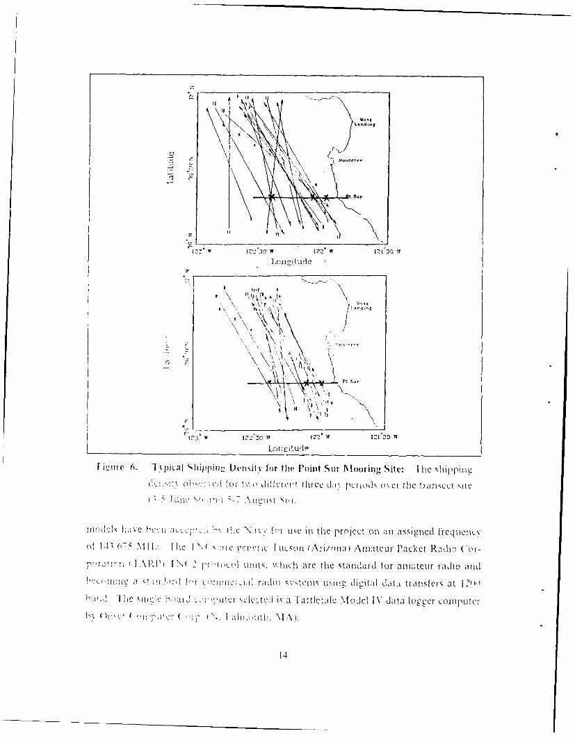
Ic..urc (, . l 'pial Slifippir g 1)cnslt\ f<,r ti/e lPoint Suii \lv>'1Inc~g Site............ .1.4
ti rc T. 1' cIcn :', ra-i fo S! 'l.lt/tn of ,\ttc l)ulaao "lo , , ci ltc ,-\tlle t ,ci
B h,, 1.V ci oFlh f i c I' !A ' IeCIC:11TT ..... .. .. .. .. .... 2
B 1} ',1 , lni5 e . (.... ............ ....... . ...........
I e: : I.' li'r tLt,' c ( a. s o B Tc cn I -r I ti c il: ,' ,i ",T., %%c:: i : ............
1: 2 . . 1: 1)t : ! . 1 .. .I ............. .... .... -..
c, c 1 2. S\R hci ............. . . .... ... .. .. 1. .......... 2
I Llrc 1 1. u ons r tl ,on I i \ for)I tile Ii..i . .. 1.', 1 )q-1.... ................. '
I !miuc 14 . nca;hcelh cin i1i hcicniic o~cr the occa (.Ivk .*1 . . ...
i. ... ..i: S . .. .. .e. .. . . . . .. . . .. . . . . . . . . . . . . 3
2: Ire I riop i I elcinctr l o Ijrir tt lCt, .dlc Po 1int SLUr. ( -A. ald R sci . . . . .
I ir c 7 . lllsIc Sl l %lifhtclina . .. ..................................... '4'
I ic- rc I S. Poi0n11t S Lur. ("A. Io %ecr ................................. 3
1Igi Ir 'J. I opncraphic Nhap of Point Stir and L.ittle Rik er 111 ii.. .. .. .. .. .. .. ... p
I i : ,iuc 2'l 1 R I S ( la q sifica ti cn of' L-\ I pro pa'ga tion.. .. .. .. .. .. .. .. .. ...... 4 1
I i cc:e 21. Iratpping vs I tectucni (M 1iller, i,S6) ... ......................... 42
Ii, cure 22. Nlontcrev (oa<tal NIeteorologv NIonthlv Weather .bumnarv Piot., ....
I gui:,l 23. 1 pical Charactcl iitic Cure<s of- Nlonturex Coastal Nleteoroloyl ..... .. 44
I iure 2-1. ENI('" Plotcction I rng Shield Nlaterials ...................... 49
Figucre 25. 12igh frcquencV pCrformance of a typical capacitor .................. 49
I i r-i e 20. Dirsharcc characteris;t.q of the selected project hattcric : ........... ... 1
I ccic c 27. 1 ( () NI cci % c r inpro emeut uqing a prea mpif ic....r ................
I ic lrc 2<. Blc lk diagiam of tile proplanl hiich decodc the A 1indcl a a acoustic pulse !--,.o
ix

d u ra tio n co d e . .......................................... 5 9
I i,.Irt 2'. l-is, , of the specification, of the I(() 02A 1. ...................... 7F
I i-ure SP ecifications for the (ushcrair Hoomer Antenna . ............ . 8.'3

1. INT RO)L CTION
A. B A(C FG R ()t NI)
1.Purpose of data collection for the stud.N of ocean currents.
Our undmriammyu oF the thre dimensional OCeanI circulion0 ill ph SIL, ],\ *~~ -~: I ie0 o; oCer th l o'' "ud c a -d . I:.-
PrVoMCn1t in W~ a LOULU )8 teuhnio ucs have ey a uded Ou~r abily to sci enti-fiLa \
L,,. rr 1 11 L I cL.c
c t' ''-'
T ~ ~ ~ 1 1:1 !,da- .
( II) If ( 11

read the cuI rent meter rec:orders. Using a telem.etry app.-oachi for near shore huo-% data
reccc erv h-is several notable advzntaces:
" IDatai collec:tion cn be in near rca' time lIast 2-4 hours) for input to prLdie:tl(io ororecastirl: models.
* Illin resojutioii satellite iSSI., SSM I :.nd AVI IRK) data can he collected in realtime to coordinate neair real time investications of current variabilities, wh'ch woredetected through the use of near real time telemetry from a ncar shore buoy.
" Expendab~e mooriitL:s can be considered.
* Systemn operation at t~ic moo. ing site Ia'n be verified daily to indicate any, syste:mch~anges res;ulting, from hostile environmental impacts such as those caused bvshi,,ping, fiSherm-en and tlr, seas.
Recovery Of OLceanogra pie data for use in near real time projects is a,) impor-
tan:t and oniteju cfl ort. Various oceanographic institutions and federal a:clcies ar.,
inNvoived in de~veloping real time 111ta collection SStemll:
* The ijvr:\Researchi In: ative iPrc_,rr (I'RIPJ) is a five %ear Ofice oi N:valRe'C~larch ON\I' !Llundcd p~_raM involving Woods H1ole Oceanographic institu~-tion1 (WI1101) NI: ssachusctts Institute o~f Techi.-oloc- , XNII Ti, and Hiarvard. 'I hie01LjLectlCS arce to auvanIc the state (11 the art In Ocean Iota collection u-s111-teleme'tr-' saIteliit~re . sensinp anld numverical ocean modelline. Under telemietr%tihe alim is reli.. '1; e:'Insfer of' da1t f~o 1,01 n Situ oceanlographic instruments to labo-rator. e conp,ter, I I OS] Ficure I shows some of' t'ie technical apocehcline inv estileatcd, at WI 1101.
.1Ta A& NI ,-, m1 i\ s an Ongo ing programn to develop the abiltd ocmu
ni,..te rcmoitLV it h roared or d~riltLin instruments using traiishori,'on VII 11te~cm!Brook". l1) _ I
* L~ S. lDcpartmecnt -! I nterior programn For dissemi-,nation of real time oceanlographicd ta fo r polic u ai11l to deve-lop an improved description and understLn eo catn circultion t iedirect and indirect current measurements of the continenitalshelf1fromn N o-tiern California to Oregon I Ryther et a/., P'-Sj.
2. Direct measurements of velocitv fields.
[)irect me rmnsoF Ocean circulations are obtained using recording, current
mecters moored at hxel cann or from drogue and 1rifting h-uoys. Cu-rent mneters not
unl-v mcasure velocit_ and drecktion. but can also measure temperature, pressure 'indconiductnit:\ N1 ic ,- ttd w tXt.i uuall have sevecral recording current meters Nverticalix
sPaICed in the Cater colum. The data sample rate is user selectable fromt minutes to)
hours and is stored in ai self contained recorder until the moorine is recovered. MIoored
in strumecntation cvpi %Ides informiation on physical paramet :-rs of' the ocean at a
pi\ n loc:a tion at aC t nine. at .J e\perietice indicates that large variations in the ie
locii- fheld call occur, over \n1-all dsae as *well as over snIlIA time itrasInkr

I 24$UISella soyI
I As~ I Ud ta
ASMI tiOM 10
Aloo~~~"9 o w=~4o!O
-~~~a EWsl ~ PIroe
[i're1 ehica proce t lenty u~S Fre,181:Sm o=h
Ct !. 92. moored reodnBurren mMersotmsariep ng ohi em
of thi e intu eninco and tohe ct o launchy ands reer of7 teSostems As' a
result, only a fewV inlstitutions are involked in direct measurements anid as a consequence
only a small proportion of the ocean has beeni observed by direct me1asurenrenlts usiei
currenit mters.
3. lIelernelry options for oceanography.
Recoveiy of oceanographic data in near real timec from buoys requires a
telenmetrv s; stem. Mfanv possibilities exist: subscriber systems using polar orbiting sat-
elites, such as NOAA A R( ( S svstcrns or geostatiorrarv satellites. The various t~ pes
of geostationarv satellites, Include GjOlS.(iNIlS MLIL] ROSAT;A] S systemis. Nonii-
sullscriHcr systems consist r'f Inch fr-equnency (I IL) for bug range radio propagation, very%
high lrcqacncv (VIII ) aid ultra high frcquenc% (Ul Il for linec-of-sigh-t propalgation and
incicnrh-urst for l inkin g stat ioans to 2400) kil. I igUre 2 illustrates the telemetry optionis

for oceanoeraphic measurements from offishore buioxs. Nearshore telemnetry is the leas t
co",!v of' thec sy-stems. because the line-of-sighit non-subscriber svstemns can be employed.
4. Telemetry methods to recover direct measurement data in real time
'I clemetrv svsteni desins vany as a function of physical anid economnic con-
str )ts.PhsIcal constraints involve the propagaticni path of the transmnitted signal to
the shore station, which dictates the physical size and electrical power limitations of the
remote sftm. Lcononiic constraints relate to the availabilitv anid or adaptability of
s vstem equipment, user fees (if subscription is mnade to a tc~emetr' service), packaging
of [tic svstemn an-, transportability of' the finished system. Whatever telemetry s\ stem is
dcesigned. thec prime con"cern1 is ade 1 mite data throughput in near real time. Reliability
o! da-a thoe>a 'a Kn1-,L.01o of, sy tem selction and plannine11.
. stem, selectionl anId piannring involves selecting the optimum telemetr\ oper-
at:o'ft 1 ~nv.op-eratinLg mode of the telemetry s-ystem anid selecting equipment hard-
\ac nJsoI \L'4t-ar. -I h 'eire, of' course.,n my telemetryv schemies of' va Ln comple\it%,
ess LL1' ',-i)C c ab deve1lped, btas a miiu.all systms mst take
Ir.: Lo c Cratton the area coverac, nLax\imn transmission path expected, terrain)
:,I " , i tepa ti ;J d Ia -ee o ', relilty requi*red fo)r data throughput.
J hC oblcctie G!f this thesis is the development of- a survivable telemetryv system
1I: i..r ci: .t ral!ie dau c &Io from' a near shore moored b-uoy s\ystenm. Thec Proposed
trnt: vtem1 for this this sapprorts a 1i:;eC Of- moore1d buoy' systems perpen~dicular
o e o aad xte d~ e ea ~a d n -1 un ie shi ore station elev.ation iS ()Ft. which
prcvidces a raiohne-ef-sieht out to the farthest buoy antenna. , hich is elevated to 7 fR.
'Iire e: cnee l rado line-o1SL1gt telen 1etI_ rv dependS On the election1 Of
aca. anot :e :&) al tionsLICeme. -1 he electroma gnetic spectrum is classic-allly di-
vided "C into ,eeIec~a s seen InI "Iable I.
4

TeleetryTrad-o~, Ic Ckenoraphic Measur nwrits froms Off'shore Buoy,
Troc.f o.er forn ... Cos .... tong Ter, li~.rTejemtrwr Cviro, core-ae Tho,tihpu ReMar'rrv Locratron "a,,MJay Per AMor,,h Per ad A-a,1j6INt sul o
*I- 1 km 1110"" 100014 Not Renu-mid. ButAXCOS Woridide ~ 002-0.2 bps 1-10 Jit~ +I- I km 1,k 5136' 10 004 Y.s Available i1$4kfW,~h
1NVA $102 111 1.002 Limited Cooeeage"
ASHi,.ai to Azores. 0.3-1.2 kbop 0.S.1 I kbH N/A Stitt 0 0 NO Not Required. ButB.t NonPr,). A-aiable 113k)
CO(SIMOATI Wolorw-de f.est 0.2-2 bps 1-2 Vbt NVA SAk 0 (Y YES Not Requir~ed. ButC.NWNSAT POIN Rev."t. Aaable t14kl
VHF 1ltirwe-.o.S*4 10 ti-nt kfroms 0 3-1.2 kbPS 0 02-0 1 Wt. N/A $1-2k 0 0 Yes Requirsed 1ISkIReter suitos
Metqeo't.Bsi 2053 km hrn 1-20 brn a 2-I vP's N/A i1.10k 0 0 Uncerun 0.e Requi.red W1100k)Matte, lwro TO ).sens-ng
liV Placketl Vanabe Upv To 1-30 bvn 1.10 voil NA %2k 0 0 Yes Req~uired 111I0MI. MayWodonde' -Fiure' Need See"ar
knwsa% Sunanf'-C WoI-+w,d F_,cept 10- 100 bpc 0 S-t IA, N/A S11 0 SO.00125' Yes Not Required
Geysta Coastal US 0 1-10 bos' 0 01 .0 1 lb,)' +/- m 1SA %4S 1000016 Hot toon-n Not Reo.ured
NOTC5 14) NCO cont'msir OrtrrvW #le W ton-e dali waes. more Power Mvst,md at longer ru'gm.(b) a ischlr. ire montlyr per, b-, chvt,, are 1r-.- or, usued MI More rsee." Star-oni remases eCfi'ercy.
data 1lr-ersout Man,-, users Per 13-9F Ito 100%) d-rc/s~vu Ip1 Sssmo% -ill en!St by 1988.I -) 1- *., r serypr, to otin data -,a 5&e~or- or o')IlIu-mr-
I4dt 5- Ig8ur 2+ Q31 Soteid spmcv technoclogy. hence lown o-e requiremenst.
[igurte 2. Telemetry Cost and 'Throughpult Options ([rye, 1987): This thesis uses
the ( I , WrI -sigll[, tllmiIv (?f)iicm. It is the least expenisive C Iystem~
and. al thoug:h it ricquircs some skill to assemble, it requires. little ski'll to
operate. _111, tlic'is details the assembly and operation of a NV1lE
N 131-MN packet teleiretry systeii for use innear shor app 0caion .
lable 1. RADIO SPECTRUM DIVISIONS: ' is table equatesth sho,51 )rt title Itfr freq uencv to0 tspectruLm co %era cc.
I RI Q[Aj:\(CY 5l10bR I SIXC1 M 'I L ( AlI ON TI I I.E (i)VLRAGIl:
Very% I. ow I req nencv112% VIA- 3- 10KI Iz
L.ow I req ucvwF3) )Kh
NI edim Frequency 11 0-300KIIf huih Freqlucric Il. 1- ',()Nil 1(7
Very I Ilch I requecc VI I F 310-30M bM 17
I "Itrahl rqaic I 103)lfI -Superc i 1L 11 Irequemic Sill- 1()(1 i/
NI riiumnineri:ci ce ft1 on1 beyotnd line-of-sight sources requires the spectrumi
en-. eiec to be VIIl- or hid icr. Below VIHI, propagation it, a function of solar radiationi

which develops and controls the strength of lavers in the Ionosphere. Ionic laver, de-
VCiOp at varMiou CevaZiOn!s III the iono0SPhere. dependingU on the timC of day and latitude,
permlittillL lawcr irca ucncv% wavelengths to refCract back to earth as a skv'wave. Skvwvave
propagation greatly exceeds line-of-sight and can propagate around the globe. 'I heC
ionosphere can also absorb lower frequency wavelengths during periods of solar flares.
WVhen the sun becomes too active, the ionosphere becomes c3-ex-Ccited and absorbs
ratheir than rcfracts, or reflects radio waves. Ni-I wavelengths are too short to be re-
fracted by, the Ionosphere, but can, however, be refracted by moisture gradients in the
atmosphecric boundary layer and produce extended propagation1 called ducting. The
minimI'Mum lev&C of" Interference For various frequencies can be found in Figure _'. I nter-
f'ercnce "is classified as noise w\hich can comne fr-om other transmiissions, man-made static.
atmo~lteic s tic c cni emsions and receiver temperature-inducedl noise.
NI oiatonschieme- also improve interference rejection. Two pr'mar% mnodu-'~Lac ae \Cd r' t:Ude miodulation LX NI ), and frecquency% mnodulto I
:\NI vaisthe ampllludec of the transmitter's fixed frequency. EN'! varies the traIInmu-
ter :r.~~ct~v a a :' caanptud .Basically. .A\NI has a bandwidth whkIh is twVic the
mno1d ltio'n re n. ( frequency plus modulation is called the upper sideband and !fre-o ::c'.u: mnus toe moulatQion is ca1"ed the lower sideband). A N Is primarilyueblo
VIIIV because~ of its vei y weak signal pref ormance and the spectrumi conservation of' the
A Ih dvi. but A NI is subljct to anl\ noiseQ amplitude, modulationIs caused by other,
a \2ottes1i the samen bandwi, dth. atmlosphei ic static. ma-aesaIc.ec.IN
a baWwdl\hIL1h varies n-on-linearly with the modulation frequency. Narrow band
I N 'VII NI has aho at thc same bandwidth ais an A NI trnn se.Wide hat id I N I
11 NI ca 11~ elI h dihsUp to 10) timeCs thc. mnodulatinilf-LLClV SIC N ie'
l~e~. c~i '~c iatton Iaid niot atnplituoe variatic ns for Jetmodulati on of the signial. 111111-
a ct a cl ppFri t. the excess; sI nali wh~ch conitatns1 amplit odeC variations can b-e
a don the rcic ed sigtial to remov)e aiiplitude noise. 1 he non-linecar nature of [ -NJ
rKtsInI less, efficlient spectrumn consecrvatLion and, therefore, is used for VIIF and hiLcher
fr qe c i s.
I'NI s inest'i>to no0i\C is at positive feaIture, as long as sufic1ient reCcei\ r conW
is a ado ile)I to ensur toAit tn. second interference rejection mechanism is ca le d
auuc. (apture Cfict isthe abl to lc-on to only the strongest signal. ThI e
ha~ e interfereinceQ Free \s hue captured and' becomes uncalpt ured only% when
e ! .Crlci Si1 ena!bcomes as, st ron- as thje (leired slic al. As a result. I NInhas a
c:J2 ovattocc Y~c .NI In neroIn,- cro0sstalk and intermodulation proIduIcts f:r0111

~IIIT
i~iH
IOc iCCR0'11 smc not
riguic~~ __IF 3.- LENiei ncoot5IitrSEr(ufc IT 97 i rj
ote eryfrequencies ['I loe0t datg vrAN Fgr ) nyudr\r
Pie e 3k sina c Niin Norml prpacatioNs FbreqVIic7 I ie-slt an very ea
s ena on i tope fralie- oi a~ itv u s icnatd Fencu ci cd in307 Mrerl desine V i
S', stems. When the signal-to-noise ratio i less thani 1, the noise canl be captured ot er
the inl but In A NI. the sienal juist becomes, weaker, with detection remaining possibie.
I heC ad cut of' digital coimmunicationS and ir)OicociMiu error chiecki"'gpro
to _k ha lis added a new di micil sioui to l able tra islinisqi onl of data betwNeen mlultiple

40 3/ -
0
z-.. 20
05 iz
0 5 10 15 20 25 30 54
Relative input-signal level,db
Figure 4. M1odulation aiafntages (Pappenfus et aL, 1964): Modulation schemes
x arv in sensitivity to noise and in bandwidth occupation. In strong sig-
nal environments (SNIR > 15 db), [NI, especially wideband 1M . have
excellent noise resistance, but at the cost of larger bandwidth usage due
to the non-linearity associated with lN1 schemes. This also results in
FNI not being frequency conserving enough for IIF. AM scheemes are
frequency conservint, but more sensitive to amplitude noise. In very
weak signal conditions, the cajturc Ieature and phase modulation dis-
tortion from noise significantly reduce the FNI advantages.
stations. By combining high speed microprocessors, memory and a system protocol with
low baud rate equipment, the low data rate equipment can be multiplexed with com-
puter error checking code and telcmerred at a higher baud rate in the form of individual
packets of information. Lach individual packet of data contains its own error checking
codes and additional codCs to indicate where in a message the data is to be addressed.
As a result, packetq of data (an be separated and transmitted by any means to reach the

final address. The receix ing station contains the same microprocessor protocol system
and will asscmbie the packets in the correct order. If' the receiving station detects an
error, or is nlisslg a packet, it will interrogate the transmitting station for a
retransmission of a missing packet and will continue this process until the data is re-
cCixed error free. The data information content in each packet can be adjusted to meet
propagation or envir.:imental conditions, such as propagation fading in lIF or ocean
wave motion affecting the antenna on a VIlF telemetry buoy. This system of digital
conrmnnications has become known as a store andjo ,ward packet switching network or
J st packet for short. I he term packet was coined in 1965 by D.W. Davies of the British
N, z;ana PhCsical laborator%, Illorzepa, 19SS1.
!he s'. ,tcm and planning involved to develop telemetry For near shore
n oorine, j, di,.uosed in detail in the next section.
B. S(J)PL
I. Requirement for real time telemetered dta
1 he Nx;1 PostL(ra doate School (NPS) is conducting a five %ear research pro-
ct,i on,. the c ( alifornia Undercurrent off central California. The features of the
Jlllburni, LUndercurcnt, and formation of jets and eddies are not well understood. In-
I r Ie-ed to determine their extent, strengths. and core structure, and to an-
sxer how and 'hx the features vary by location and season, and what atmospheric
.:. . ., . % \iid aro ons. in1c, u :e subsurface fea-u, r s. W ith a real time
C t1cr" C t pxidi data I'0 m current meters. a n \xinability noted con be im-
mcJ; t Cl in, \Cltljated using satCllite imaccry. ship cruises and weather buoy data.
Tlhe Naval iMiromental Prediction Research Facility (NIIPRI ). in Montercy.
(A.. is dcx elop:ng a capoblitx to collect and archieve high resolution data from polar
orbiting satellites. The data will be Sea Surface Temperature (SSTL DNISP Microwave
Imcer iSS!I I) and Advanced Vern Ilih Resolution Radiometer (AVI RR). NIPRFs'
interest is to provide the ability to conduct time series research along the California coast
usil SST. SSM I and AVIIRR data (Boyle. 1989). An adequately instrumented rid
of telemetered current meters aids in the utilization of satellite data and will allow
(Robinson (' oi. I (S6)
• I-or the first timne, a real time dynamical forecast of the oceanic undercurrents, jetsand eddic'.
* Dcx clopinent of the mcthodology of'nowcasting, forecasting and data assimilation.
* I)e,,el o -ocmt of methods of dynanically interpreting direct measurements of thepi .',,ic,,l fi i i ne rshore recions.

The present NPS system design is an array of recording current meters deployed
and recovered at six niontli intervals. The proposed mooring sites are as shown in Fig-
tire 5. Ine recordinge current meter being used, the Aanuraa Instruments recording
current meter model RC:\IS, sequentially records six 10 bit binary words: a unit reference
1 1her. instantaneous measurement of temperature, conductivity, and pressure, and
vector averaEged curren-. direction and current speed at a preselected interval (0.5, 1, 2,
10, 2,) 30. 60 or 120 minutes). The rt:,r'ier has a maximum record storage capacity
of Iu.9(0 records, each containing 61 data bits. Tablje 2 indicates the maximum de-
ployment time for each recording interval.
Table 2. RECORDING CAPABILITY OFAANDER,\A RCMS CURRENT METER
Record Re ,Dy laxinmmtR e-, r J ReCOr dsNIi 111TII nterva I L v Bits Per Da l )ploNIentmnlmutes) Period(do.\i
12( 12 72( O()S
12,- 2-_-_() _ 4_5_-1
___ __ __ _ __ __ __ 2S n --
432() 1511 ) ] 1-1-4 {'o-w( 75
2 2 , -1 2(()
1 la)S €4-I)() 7.5(I 24o l2() 4
Ihe minimum RC NIS recording interval for a six month deplon,ment is every 3()minutes.
I his equater to 2SSO bits of data per day. The RCM S is equipped with an acoustic
telemetry system using a 10-bit pulse duration code at 37 baud. Acoustic telemetry is
received %kith an Azwi'craa Ihstru sns hydropho, recelv,:r 2247 which converts the
I(,3.4 IIZ pulse duration code (I)C) format to an on-off keyed carrier of 0 volt pulses
for a 2- m P)(C and -(, volt pulses for a 81 is PI)C. The voltage pulses represent a
(0-bit for 1) volts and l-bit for -6 volts. Each measured parameter is a 10 bit word. 0
nw . t-cd pa raneters ni.cke up a record, and each record has a sxnc pulse for a total of
(1 , per record. A hardiw ire connection to the current meter can be made via the 29--
CItriW I0r/7i1,,1. Ilie acoustic interlacc ca prabilitx has been researched by Frye of-
lI

\\ I 10 I w; o has 11 11ntI1c Aa niet aa lvj roplione to be less, than optimumi for reliable
dlata reco. cr hx a I(A) meters depth ;eparation between the h\ drophone and the
RCNl\. 'I esi ondauctcd as part of" this thes is at Sea i hapter 4), ofi of Point Sur. CA,
on!firm that error rates signi ficatt] increase beyond a So m depth separation between
the hvdrophone and the RCM S. An improv-ed error checking hardware and softwvare
system w\as developed, but w\as unable to overcomeI the acoustic path limitations of the
h\ d'rophone or the RCNM S. Even wvith the Aanderaa hvdrophone error rate limitation.
the available data can be exploited for radio telemetry ofxwhatever acoustic signals the
RUVM \sds dtafrom the RUMS can be- processed once pncr da . then a near real
::mc ::VN: a 2n Lon Fchieve anj tme advantages sumnnariecd prex iously could
be readwed I he fac remains, the Aanderaa acoustic eqluinent is the weak link to an
L RlIP r I QW 194 - CQ l atin £ an impro ed acouIStic data iink f-or tran smittin c
ro aaordinstruimcnt array to a surface bu oy. 1.RI P wiil set a
ior acoustic nodecm desien and solicit the V RI P or,,cani/ati on and com-
~ ari '0 c n~o~n~ r te~m .I his re search Cii or: sh o u:aa narocd cca0iclink for inerain ith tll' hi prjec1t s telemeItry sxsteml.
L. DeSign LOIISilerat ions to meed requirement
a. .\..'r shove buoj- sins ein stratu,'ie' '_ ' ;. I he: inta .e~ ,ra 3 *s I
'':1:2 my.: e: cc ::.vne of, the,, sea i sliipping. fish ing AYt and the sea en-
r I' ~c ida u arc phvsical1k 1arge,. because of the reqjLiirement to
nuppw' ant A. ra aion aid, such as Iion ts. radari reflect ors and batteries. Sta.te-oll
tcr cn,, .trx o.xmtms for iinc-oliiht systems are solio state %nd small in sie. Re-
mu a *,. no. :eat~o:;, cadeve the Lcntet of any iiWooksight telemetry s'. teminW
o sac I ed ' a r KaJ1Ce to consider eva1uati n a fLop-ulp buo package. which surfAcs
02Lc a On% to trn snu:t the stored data at a ii ih data rawe and resubnmcrcs.
'Ihle proposed pop-np1 -uox' sytmWould consist Of' a1 SUlbmIcrLC
rmon at 01 mete>, bemcoth the water. proviin ladranICe lr deep draft vessels. Th le
a 2:..cd P!a v.: ! n a , the SC61 cic0sci ;Of a ii 5 d moo re'd rC Ori n e1 current
nmcvc s; vtem. It would cm'taic the :\anjcraa hx droplione receix r. data eoliecmii
en n1) InaT er. p >e: eri: a n de! control Icr fI NC). batteries,, winch and a haul-down re-.!
e ic a p it to Cce the xic onC pcl dayl for a'I~2i cc c~nx::.AK 0%. W rLAWe, with tw'o ramwr of AN gagCie 'A woud link the
C . I. ~ .. IhfC bi'ov k\k(m xoi'l nounse the VI IF

STATION LAITUDE LONTUDE D FIii DISTANCEOFFSHORE
Pi 36 20 N 121 58.5 W 100 H 7.5 KH
P2 36 20 N 122 10.5 W 800 H 25.0 KH
P3 36 20 N 122 28.3 W 1800 H 52.0 KH
San Francisco Boy
0037.
0
' Moss Landi,,9
*9 Big Sur
-360
00MBARI CTD Section
* MBARI Mooring
- NPS CTD and PEGASUS Section
* NPS Mooring
1240W 1230 1220 121a
Figure 5. Transect Mooring Positions off of Point Sur, CA: The project uses
mooring stations P1l. P2, and P3. Station l1 and P2 are well within the
free path propagation for VIIFV radio line-of sight telemetry. Station IP3
is at the edge of the free path propagation linit.
12

trasce o. aV I I rcinrplifier. battefies Und an~crtina. T he bumx would surface once
peor day to L.-anm~ \OIho .1ai!% rcor,! of- 2W 1Y'0 b, 1,!-,a prc, cur rent met or at tached to
the moorn .. ic PNC hn, data rate tral~ <or 01T 2 r porQ1o- . i the daais
tran',Crrod inl Packets of 119'6 bit I 2S data hts tAms eight plu another P 2 bits fOr
error checking and. aJdreNs:ng oxerheadt A. inaninam of 23 trallmmssionq are required
to senid 2SSu bits of data in the error free Ji-i rnt S' data bits 1 2S data bits transmit-
mun. w*x roi: !,,unmo nN ire requ ired to0 Ljour adI tofon i.rx errors .. \ ter the f ii 1runs-
lission hehuox %vouA be rosibnxcrged.
I.. tli,l,\x.d~aisrt tilat a pop1-upLJ nu' Srton is 7,oss nIe
hocaaso 1 0 r:, Ax/C 0 ae uox Q pa ; 1: A. I o ;"Yp a as 'n ' xi iw ro
S... - '7:':' , i0 M T'x ' .
a. a1''an'itl:;.o Lnc&.orl' :a ia:ltalo i tii~ons 1"I 20:.
inA.c \hoc semor :: jiai a..Lc' arc in'.M ins the vanc uIx . :
CA. ~ 0- Iav 0 W.A ir Il II IHNI ~a~e.c~andl I "A arc .. ',:n n ateUr
m2;. .: up:..on, xx ii Arc akO Manufactured for' conunorChi] apli1Catos Cl hos-
- a.. ca~a. :or a the !-a-,, is an I( ON! (12A] , 5 1'aV I d 22 an:
Ao:Iii1 NIL, I ' 19) NI / and hir the shore sta, an R0 (51 2-A. Y
al...............i l'oxxj- 12'f NV 1/ to 11 VI NlI./. 1 I th rns."o
3 TiNO
12 'W11-,0VF12
\nng ude -
\' IsK 1 0 ~ n
Czlaw 2
Loneilude
W m . i." iipmfD mi fr h ut urN m ngS E esh pn
Moo oh :c o to der hcd m d oiiteN M I
i ~ ~ ~ IT nII ha!0- uu w
rimkick~ ~ ~ ~~~~~~~l haI i~ mcM ~ ntepnec n-nasge rqc-
() W -- l./ cIV IJCg ~ L M an M m n tu ak a i 'r
MA).

I.''; {'si L It .ost cil c ontponents is aiwa> I In ci tot iCor
o lt::n ilx ! c~s Ic I ceIp to en Isure lwcr Co""". :xn ,: -
111. ri: :n e- a11 a !tow% cost reVti ye to comnmercial urade ccluipment. DY. 'crc
rcJ o I Jm a raC) opecra t urI to0 kee p tl~ co0s ts lo i0 colll;:1eca tii
I who' suLpport maeu radio haekept their comimercial rduiO f The
N'. 'tO: 1 . Unatc J an c :,-L1er 1 :aIUsers. Arppe:;Q A \ . j the r:.
~rtn2ita: r c opotents purchatsed for tis project.
I. 'z'r.A SiX rnc' :h depi omn c! Ofthe huOx ' :e c
:N.wcr~<:> ~fl tic h a ' low ar ps'ibel to krleep the1 teeh an;1.e h
2 *''T.' 2 :e.: :''' . I luc :asec r no "Cc I'''rrcar C:
rcl)
V 12' t ?I' pcn.~-' ''''' I
o u (~~ N.>N- h ':,
*. . .'.. t I'lls I.. . . . .

b. Procedluve Jbr automnated teletnetv
The hear of an automa1,ted 'sNstemi is a computer that can keep track of tiMe
and ~i~vto: euccothler equipment in response to prograinnn anid cternal
s.1e-nUls. The Onset Tattletale Model IN' contains an internal counter that is incremented
1' cr0 01I'ofa seco:;d. and uses a clock varible that is incremiented every 10( inS. The
clock variable counts inl hundreds of seconds and overflows at about 200 days. Pro-
crmmneOf the clock variable can provide time anid date of' occurro-nc.es of events anid
canl also cause events to take place. On shore, comparing telemetry transmrmssion time
to the coanestelemezee lock \IC aral-)e time will provide a relative measure of! the,.
compluter-s timie saiiy
This1 out11,1%1 emtedSxsteml IS pi eprograinred to have twc- main function1s.
I 1If:c /irs! is I,' mflifit Mite -1 waeraa im idrt,'rla ,c receeger -I;);
ri: .The ,1 hdropione ei': sends out 2T ins and SI mis pulses on triecers of I o,1".-
I /f.ile, : l ~rspurius, or- intentional. Intentional traininss:ons aire in a d~
quea:1e au:-Iae 11Cng lecomputer, is procraimlled to diflenCltiate ST)Urmoas &:
foIre. aseeucr it! yro n si--nals. Once an intentional sienal is stored, the conmlx~ce
V,;. <o1 o:non 1h hydr ph on ) r 7 of t-L eiiiotrval timler setting pese a.C in lic
2 -l Jesecutht til ('cjm7 I i( -h7 teeme " ~u t the s/,r sI'C I :' C; I\ Ie
pov eris pp edto the 01)n-et the ,,tored com-pumer pra cram 1 which rcnmum ns a;11 a
1e: po Cr 1, 0- :or unI to 0 maiortic due to a 3 v oIt t lium ba ht ter i's t22ut. Ih
starI dIt is 1 at Uoiwl oat.OfICS5 chanl1-Ced at the timeI Of' power1 up- \1,1 the
R 212 port. Orpwe up. initialization sequecIIUs atre programmIned to set vaiales andsat th neprJytlmty \t binput output dizitl part and -i analco
~~.:~:tolc ihine th toia:n a e quite elaborate. TIhle presemu arranee:,'lvenlt ut: liia nutomptIics to: I )turn onl and ofIfthe VIII1 transceiver and pc p e
and TN . 2 lo for- l-,alCke Colhet te sic'nals anid pL eket (.lwt''esi enais from -he
o Wr .lc 11,Jr(Ti~ rCne recvr ipt.OrIe anlog0 to dialcneliPCuse
n r 1trohc : r t,)n 1ma), oiC evl durlIucl the evaluation01 peio1d. I uture 'C :
e '' t,11 L cnn1e~lias can1 he us"ed to 1masure Internal batter\ voltaics or any% other
1)c: a ii onl the particular azatoma t ionl fear. ares arc di scaN seI in ure ter

c. Revies' of rea.%ons /w !selectitkz, '1fF A'BF!J1 packet lelemetin')
Previous sections contained anl overview of considcratioils for sciecting
line-of-sighlt telinctrv. This section reviews in greater detail the technical considerations
for wh-v telemetry on the VILE spectrum, using NI3EM.\ with the packet data transfer
mode. is the best modulation schemet for line-of-sight comminunications to near shore
buoys. It is important to understand the technical considerations so future rnodifica-
tions have a benichmlark to deviate from when making, decisions to change frequency.
modulation scheme or the data transfer mode.
The t- RI 1) 1s tasked to evaluate v arious high data rate telemetry schemes for
get ti:ne data from a sUlariCe bu1oy to shore. T hey intend to develop new technologies
Frxe. 116s-h. Bx providine,, sufflicient detail onl the tecfmiical considerations for this
project. changes can be addresscd rationally .
I 11 ~ ' suWmd, Uinder the UiRI P progcram at WI 101 the
teleme.itry project teami e\periniclited with a digital packet radio link enl an assigned VI II
enanlo:~i 4 . NIi 11A Ai ruamex is just outside of tie an~ateur radio band of*
144 to I14S \I IA Ii.Te amateur eq uipment is inexpensiv easilx attainable and is capable
ofoporAt i betv. cu the frq act :icc of 1 4, to 13) N iII . Packet TN\Cs, whtc II were
developed b-y the amateur radio coni-nit\. were also purchased and uba. (BIrincoe el
l~cl ~n~rxev\priments hl Brouks Iu3 Found VI IF telemnetry
systems Wwsited I or use in near shore applications. IlIc found the eq uipment to be
ine\pensive. rclativc> simpistic and found to have wvidespread applitcations to open
o-eanil al %Vt- 01, near , ore01- oCan studies. The real timei ca pability aliIorded bky this
eq uipment has, a definite advantage for accessing data and monitoring instrumnltationl
Hr. Iis expeclilecits demonst,,rated' how the real time feature is very useful inl
Ahowmn un expected current fluctuations. The experiments in vokved VI II NBFNI
eq npnw. and used the b- aud signal frm the Aandwraa currenit meer to audio fre-
q~uencx sN: Kul. A\ ISO KAth NB IA! transm)itter. lie was concerned with uinder utiiliine
the rULeiver bAWdh Shannon capacity theory ( Schwarti 1901) addresses this el-
civas chanl CO. O paAt: biseccud). whkih is limte by bandwidth (Ii i) The signal
ha. '.e( a as,:a a noise aIS follows:
C In( I + SAT

Statistically, the closer the bandwidth(W1) is to thle channel capacity (C), the lower the
sILenal to noise ratio (SNR ) can bc and still maintain a virtually error-free digitzal *rans-
;-lission. This theorx, Indicates that a linear increase in bandwidth, while maintainng a
constant channel capacity anid constant Gaussian noise level, results in an exponential
reduction In thle required signal strength. By using packet with 1200 baud AFSK to
modulate the NI3FN1 transmitter, the signal bandwidth approaches the receiver band-
width. resultineL in efficient bandwidth usaze.
(2) Operating frequency and frequency allocation. Line-of-sight telemetry
is optini.ied by using the VHJF spectrum for the following technical reasons:
" Lowest interference (noise) is in the 140-150) Mhiz Spectrum [ Figure 3].
* FTCrce-s CC transmission attenuation ( o. ) is a function of frequency and distanceI] lanislier. 19671. Figure 7 is a nomoeran ofy.. This shows that for a viven dis-
tac.the hie~her the seIlted telemetry frequency the greater the line-of-sight at-t e'nuat llL
a- 33 + 20 1oc! ]4c: -201 lo(2( All/cs)
Note: A,!d't'OnaIl losses occur w hen the curvature of the earth is betwe en the twoanltenna'i !:i0-of-Sight paths. seeC FInkl. 1 957, for losses beyond the line-of-sight.
For lhe a hove reai~un, a flrequnc\IC allocation was requested and approved InI the 14 1 151)
Nilz spectruml. IIs frequency spectr-um has an added advantage that inexpCnISI\
teemtr eaupmntis als o available for thle 1.4)- 11 1Zl spectruml.
3 s/vlia! t') llolse 'SNX eurnvi71C1. MIaXirnizine SN R attemplts to.ct~ Ch iitn hurinlation %iTh1 thle least degradation froml nloise. TIls is done by
S evera.l niethod\., lhe simpiest beine to increase the transmnitter power. This canl he done
olvif' you can afford the exponenti demiand onl electrical power. rxdditionallv,
Shannon cap:-"lt citythory statistlcalil states that if'tile ci~annel capaciP, iS fllyI occupied
by dat usin a proper enlcodingL schemie, then thle SNR required is low. if thle chanei, not1 fully, o(ccuied.C thenI a igher SNRP is required to ensure error-free transmission.
T1his demionstraites tiec relaitionships between linear change inI bandwidth and chiannel
capaIcit%, to thle Cx ponenI'tlil ChanI1c III Signal power. Finally, the choice of the miodu-
Ianon ~hin~s a1 c sS\RP. Figurc -4 illustrate,, that under equal carrier powver. with
mo ', idulationi and equail receiver noise figures. FMI has the advantac over sincie
side band ISSB and ANM. I lowe ver. under very weak sienal conditions thle FMI advan-
SNP.i not always the mnost importanit requirement. I uformnatoun
, Q: ,, J c (: IT 1 r at' a tilctre 1,(r t.'uilte linformlation Content to be tasitd

d! 2fdistance, at tenuation, wavelength, frequency,
km miles db cm MC500--300 1--30.000400-300--200 170 -20,000
-16 5 2-
20 10010
155 3-10,0004-
100- 150 5--50 145 - - - - 5,000-40 --- --4,000
50- 30 - --- 3 10--3,00040-13
30 -- 20 -. 130 -2,000125 2G
2 12 010 1530-1,000
40-10 . 1105
- 5--10 - 500-4 100 400
5--3 9o 510 3004-95
3-2 90 2002
2113001100
Figuire 7. Nomiogramn for- Soltitioji of kttenuiation a Betiieen Isotropic Antennas(F[ink. 1957): 'ilhe most lirni tine contr-ibutor to line-of-sight operationsis the heitlht and distance between antennas. I1 his nonmograni illustratesthle expected loses dIue to dlistanice to the o diadl horizon fine-of-sight.Th fe solid line is the or for this, dcsi en and the (lashed line is an examipleof' co at radar f'(IVe iuces. 'I he higher the oper-ating 1frequencNy selectedth,- great thelos.
Lnrtropv Is a statistical e alu at ion of' 11lormla lion and thc probability of uncertaintVa
-to thle outcome. '11h higher thle enitr-opy thle lower thle uncer-talinlt% ini a systein As an
exa topic, thle ELogiish language has a igvh entropv, coipa red to a non-error checking
19
coded language. In the English language, as many as one third of the letters may be
onitted and the message usually can still be determined. In a non-error checkine coded
rnessge, however, ccn one iissed letter can change or destroy the message. Conse-
quently. redundancy is an important element used to combat the efl'ects of lost signals
due to poor SNR. SNR for this project is maximized by having the data rate capacity
approaching the receiver bandwidth and using the FM scheme. Entropy is not an im-
lortant consideration when using the packet error checking protocol, because the packet
protocol can be adjusted to overcome either poor SNR or error rate by readjusting the
transmission length and retransmission cycles. With packet. the low entropy of each
packet transnission requires a noise-free environment, but the error checking system
requests retransmissions if there are noise errors occurring. The error checking scheme
no, permits a lov entropy system to operate in a higher entropy mode. with more tol-
erance for noise intCrf'rence at the sacrifice oflower data rate throughput.
,4. [LDUI tr V 1'r ,udC compatibi!i'. Several methods are used to tele-
meter dA ta.\naloe data telemetry, the first method used for a long time, was subject
tO '10ose and d: i'1. lmprosc ments were made by converting analog signals to digitad
format, resulting in reduction of the noise and drift problems. Digital formats required
a :1-ioilIator and del'odulator (NIOD NI) to improve tranlmmislon and reception of
digital sigmials for direct input to computers. Modem designs require evaluation. Some
modems operate efficientlv in high noise environments and others do not. This is a de-
sien 1: i'at ion and1 not a concept limitation. (Broks. 19S3)
-lie comb1-,inatio'n of microprocessors. menmor., software and modems
reso its in a1n errr chekm e ,tore and Itorward digital dita protocol. Packet data tran,-
fcrs are part of this new te.Lnology. Picket was designed by the amateur radio coM-
nvamitv to operate t le ar the chtanncl ca pacity of the receiver bandwidth. The reult i's
that almost all VIII NBI NI transceivers used by thc amateur cotnmunIty are compatiblewita patcket cq;icnt.
5 Iz 1':14o/'',i:t; waiaibij. Experiments to date by Brooks (Texas A&M
(Brooks. l9S3 . Briscoc (\VI 10) and Frye (WI 101) Briscoe and Frye. 1987). have found
that telemet- oy c a i cn take advaltace of the inexpensive amatcur radio equipment.
:tnd Uie packeCt ' Is Ir an c1tlcti\ e error-free, real time data collection system. -lcir
applications focu'sCd oni eFcater than line-of-sight telemetry. By using the refractive
propcrties of the ifo>nini crc icr IIF- they could cover several thousand kilometers and
by rcfracti e prorcrt;c l o! tlic marine boundry la ver for VIIF and higher freq ueT Li es
ti:e% cou!" taikc avant, oc of'any trapping layers. This thesis will use the same types

of equipment, but will specialize on developing a reliable line-of-sight only telemetryS1V"tc!lj Which is smaill in size, has low power consumption and is low In cost.

11. HARDWARE AND SOFTWARE DETAILS OF THE AUTOMIATED
DATA AND VH-F NBFINI PACKET TELENIETRY DESIGN
Proectdevlopcntfocseson mal, lght weight, low power and inexpensive
equ11_Inment for useC In a pop)-ip buoy designed to provide data from near shore moorines0.
U~RIP researchers are also investiuatine this same approach to develop similar system
de,;icns. The commercial market has various telemetry designs. ENI)ECO Inc.. Marion,
MA. sells an .- laPtiv PacAct Telenetr-Y Syistem." 1The ENDECO systemn works, but is
niot desiL-ned for use in a pop-tip buoy system or for use in listening for Aanderita current
ivet"crs ox c:r anl acoustIc lin1k. The1 software is proprietarY and is riot easily adauptable,,.
O),hlir coinpanie", Such as RLPCO Inc. of Orlando. 1FL- will provide discrete equipmnent
rallsfor' dcxeCloping2 systemls using a fixed f"I-CCUency and prox "Ide their owvi n modem
s tm.ReSearchers in VI II:- telemetry are not becoming product SPecifIL. butarusn
paaicdominpacetsoftw~are anid equipment developed by the amateur radlio conuno11.-
'It~ 1hs prOjeCt Will discuss indetail the hardware and software 'nterfa ci for a sinele
1hoxay station,. expan1sion of which onl1 req uireCs bildinU more buo\ s.
A. BUOY SYSJ1E.M\ PACKAGE
I hie bai-Jc tclectr oxp 1ace i*s illustrated inI Siur . Illustrated IS the buoy pa1ck-
aceanathesI orestanonma~or omp i ets. 1 he buov conta'ins a single board comn-
puter. palcke 'I N(C. radio transceiver, radio piceamplifier, power siuppl.%, anitenna and~
instrunt pakag inflaIce. Thle shore station uses a generic comiputer capanlJhe of'
Rs-3 -Interf'ac in, p act terminal node conitroller (V NC. radio transceiver, radiope
amI'plifier, powe r supplx anid a 11L,1h L'ain antennia.'Ie 1'eC Ofnc Ci I ipIenx operation) is as Ibll1ows:
*Sinele board computer on buoy stores; data Fromn the instrumentation package anidC(ontrols thet timei of telemectr% trans mission (once etery 2-4 hours).
*WI ion the time for telemietry occurs, the computer turns on the -NC. transceix era ra i ile. Iheco Inp11-uter theni will Initiate a tclemectix connectioni looin to
'I lhe shoresato is alwaos niitorie for a connect seqLIinCe to a seia r , r nioorkis idcnt ified In its programn. Once coninected tile shiore stationi
er'' :-_ oi: v error ree., dat~i a. the data has an error, the Shoire stationl %%II recI s1t
a~~~~P1 Clr'tia"B fthe data.
* Ike buo'. comlputer chcks the 'I N( to ens'ure all data has been sent and then lni-

" The shore station disconnectS.
" The bluoy com~puter secures the T\(C. transceiver and preamplifier on disconnectand r-cNsames instrumenitaltion monitoring.
" Thec shore computer remnains on standby for future transnrussions.
-1 hie renming sc:tion details the individual components, software, functions and
piirameCLe.S Used in the sytmdevelopment.
I . Automnated data loover and s stemn controller
Thle automated data logger is a single board computer made by ONSET Corn-
pate: ~: . of .1 VLou . alled a! Tatla NI odel IV (114). ( Fic 9). li he
TT4I'- has extensi~e versatility in a smiall package and low power requirements. The foa-
tureN oC tlic omutr ar:
*' 3'K orpoarmn.variables and storap-e
*~ ~~P IIci nn>10bt A-I) ratiometric. converter
*22'x .725 x (0, phyS*ial d ImenIsions
-I -limait"~ 12 volt Power retI.quiireet
* Tattletale BA;SIC operating system F:SC
* 13at~' PAcdRNI
The on., moIdfILitions required f'or use in this system) are adding- pr-otective
'ii'''x al !n! 'jratinO th e I'2 CleCTronics, Imn the P.S22interfa ce he
C --.- C th redoard ( 'P -A .1 ie protective circuilt diagrams are iutredInI
The11 1 14 is eaSily programme11d uISIng anly computer with a RS232 connection
anid a Lceneric iiioci r. rT.he programn used for commnircatine with the TAIS
PC -TA LK III freeware pro,-ram fr-om an IBNI PC public domain library). ComIi-1-
cation1 PLramerercs are )0()( baud. parity n. data bits S and stop bit 1 . The TT-4 is set to
1)(411 baud bk C\Ccutizine the followint- lie: XN 16 ,,SN1X,DB35. The 96)) batud Is used
tC) ,oinun icate bewe ~TT I ~ ~ N -nux;mize monitoring efficiencv of the
1-14. -I 1 BAS I( (ia tuoR,dih BAS IC lancuat-Ce Or aissemblV lanc1ua2C can be used' to
1Proe-riams used In this project are all written in 11 BASIC . Appendices B. C.
1). V:d 1 a-,-, np pro(ject related programs. File pros! ains are stored inI a
I'( -1 \L K III fihe, and canir be uip or down-loaded to the Ti14. Once the programn is
the h: t crx a ke RA\NI 11 i1 maiin the program for uip to six mionthis wihk u
2'

BUOY SYSTEM SHORE STATION SYSTEM
WT MM-2 KK Lo
Figure S. Block Diagramn of the Basic Packet Telenietr Systcan: 'Each block Is
an individual piece of equipmecnt required '-or one telenmetry net. I1his
system can have I to 50 or more buLoys interfacng with a single shore
station.
ex\ternlal power applied. On) application of external power, the loaded program executes.
Appendix 11 1r the primary program listing, with remnarks. When the program is loadedl.
the remarks are removed by thc 'I1A. The system operating program is block d-I)
agramnied in Figure 1l.
I lardware mount11ig conifiguratioo is illustrated in Appenidix (9.
2. VIIF NBFMi transceiver
'Ihle transceiver used in the pop-up buoy design is an ICONI-02AT (ICON!).
from iiiI ( Inc., Osaka. J!a pan. It is a si iall, light weight, Freq uency synt hesized,
handhield transcei\ er. Thle spiccillications. listed in the Appendix 11, are the typical pa-
24

Low ULhium Vonace
Tattetal Moel,
[igu' k . Bo optrh N [: 1le14i utoato c ore othe~~~~~X buyssc.I spogamdi]IHSI ihabteybceRA oriiiaigProrr tr-p oe srmv n the 're-
a2pplied. Ip.rametrs epecte &onmostliandreldtranceives usd intamter and comrc.
a nv !rq uenc ho S\ 4U- I t i s.l. peorame ttion an I AIC wtabttelemtr deig bascon-
RANIfor nititinga prp-amstr-p ifpm ire oead hnr-

POWER CONTROL CIRCUITS TO TIRN ON AM OFF THE RADIO AMS INC
+12VI +2V
1 OK ?N222
+5v+5V
INP11T DAY APROTECTION lOOK INP'UT DATA
PROTECTI1 IOOK
21NI=22 1OCK
PAkCIET :742N222
0c~ CONNECT
DO PIN D12 00PiD
OV'TOISOLATOR USED TO ELECTRICALLY ISOLAff THE P1DSITIVE GROUNHDEDHYDROPh'NE FROM THE N~aAJIVF1V GOUNED TATrLEJALE COMPUTER.
SK2084
+O5v DI
riur 0. Potcii irut~Tet~enT1 ndItefcig2qimet
ducte 6n theU 14-18 17amtu aiohnwieaatngadsntefrunc
Frogute 1a0. A reqenCicuit ws requeted1betwnd 14trfain Equpmeznd. treih
mionthis of processing by the Navy, an assignment of 143.675 N1I lz was approved. Ap-
pendix 1, illustrates the requesting nmcsage and the approval message. Navy pulicationl
NIl-0 B), Annex 1), cna.ers message i-oria ts and procedures. 1 hie I(0\I-02A1I and the
26

GTART
GET VARIABLES CONVERSION
PROORAM
MEASURETIME DATA READY
EE S
n M
TIME to no STORE DA7 A YES MEMORY
o
TRANSMIT
YES noTR
"S
I URN ON RADIO IncQUIPMENTTIME 0MT=MF
TIME DELAY 3RD LOOP5 SEC no -REACHED
YES
No IOTH LDUPCONNECT r 15 TNCREQUEST REYWIES RFACNFD
TIME DELAY CLIEctSE
ykS
(1117PUT
COMECIED ljo
D
AyDATA
Airy rACTET rES T" DELAYyt
SN " ii iE a (Z)I-REMAININO V AARR IIIAA ROLE (Z)
No i t!
DISCOMECI 15 T NCRETRIES
ORDISCONNECT
IJRN IFEQUIPMENT
DFLAY F[WNEXT CYCLE
11. "14 )Nstem Operating Progiam Block Migram: S\steiii block dill-
jor progiam logic steps of the program in Ap-AM OL ItI111111C tile Ilia* I I
pendix 13.
shore station trirismcr arc amatcur radlo equipment which the Navy ha
acccptcd for opmition oil military fi-equenc](1s.
Several modllication aic required to prevent rl)Z1lf1lTlCti0hS dUring deploment.
All contacts alld L9',)11C(-t0]:, are removed arld replaced \ lth soldered xvire connecti(All.
27

Ani '1dtiorna Connection was attac:hed to the sional-to-noise ( SNR) mietering, circuit for
e'l a lat ion and,_ lerCor1IInctest Te he S NR mo1dification IS worth m"en ticaine-. be-
k:.1iUsO is \Vas U\OYI to - iten perfOrniince when design chanves we rc nude. A hieSN R wswrdto an anlalog: channel on the T14 and by programming the T14, SN R
\ me kerc atiable. The SN R tap is shown at a point just b cforc thc limiter stage
o f the inteeraed circuit 1C201 In 1Licure 12. between diode D202 and capacitor C201.
11\; t 1as x "n po!n a long Cuprwr can bec found. which runs across the bottom ofthle ICONI.
VioICON! control settings are preset as follows:
*Power onl
*Power se 11Lo In1
* 1 rca ae Cvst a A okd Onl I47,.(,75 NI I z (internal batter% basK-ui
l ~ ~ 0 pa pp. pv cr Cron tile 114 e FiL1ure 11)). theI 1C0\l comens on at the
prr, rreso''I I e1 z -~ htcan be thle mos01t difficult to set IS 11 th lel ah. It ms
'~o d~a'cJ js' '~oao tocu! Out aill th;e b'acheroan:d nu~e 1 hscan re1
P--: b: in t'ai th set,,tn in the lab and at the m arim- s ste inax\ be quite difl-erent and
wa r;:o I x et i~~ bfoelaunchine_ theC m1Iorine' ('1i t J nS a nt een' a
or the P~oint Sul, (j_\ ite .
ii :o ICO ()L u( N c01ninsS.1ni 1dLi squeIlched. reCcive and I 30) ma dtirin e
ti nsit.Acualtrnsat ao~r ranmitedisa fncion Oi bater\olae he hieher
0\laethe ll:hcnr the powe '13 C\it, S watts an7.2 vot . ts I heC
a ~___to':n: ~hat mauts pr d;. ittet sctilon dijLSNCu5 , ba)tter% SC-
.c. t a con dora on s for maximum! power olut put undcr surgeC Ioadina. condJ!iCons.
J ard1 'va:e nC ntn can ;-* L'L11Ilnrationr 1 Js iluttod InI AppendCI\ : J.
3. Packet terminal node controller (TN(.'
The 'IN\ C selted. F(or thepo-n buo'x is f1,on1 Packet Radio S'Stem',s. IncL.
I.(' of I atn. I. an i, cal I d L t!;e NI[ Mic.ro-2. 'Ih;, T NC xvas chosen a 'o on
i!,s C c and. in crcahirV u the. (7NIO)S inteerated circLuits 0n11cn1n\
w. e a t mabrnd a 'il iblc. but few operate at a Ifoyer cona suni on as
Ia..% a 4f, 1"I. \Mast brns La; ti ac RAM\ capaicit'x fo(Ir the store and' forwad, potocl),01
macno I Ci rN Ia c;".-1!n V RA i-%iflI sto)re thle 900)~ ba1ud dalta fromn t:e 1 14
lx C.u 'I 1i I INJ, hamu..Apit Kmu

IC 204 iSC-1025 PA module)-
0210 (2SC2407 Driver)-
P2G9 lLowv Power Adjust)-
R267 (High Power Adjust) - . 3 0206 (2SK241 PP Armp)
Divder 1 243 (DeviationAdut
C287 (X20,1 I requericy Adjust)-
X 7C3 15.1 21Al z rlereirce -60052192i 1eF requpcy Crystal) 020 (2SI9 flt ______ ____
IC203 (pFrD2834C PILL IC) 01___ ________ (w
P1205 (S kl't-rL~r Adijust) t.Jy2nI cr-Iu4-cF 1202 (161 0502 Crystal Filter)
Cerr'rnc Dlsvjrimptor) ____X202 (16.445MI17 2,,d LO Cry'stal)
Crl rrl Fl)C201 t\ C3357P IF Circuit IC)
IAP __ -C-_
:25
rigiiie 12. SN R WXire Jap: Wirc tap pinM~t IS illUStIMatd anld U1 be located by
rcm-I ng thu~ cover of the I (uM% and tappingL in1to the F ir, which
L:Is aIcross thel h-OUtto I. eSC heniatie on11y shows the circuit sec ti o
of rltcr'2st.
naillaV1c fol colncctioln bet\\ ceo thc, compute and the I1 000 h9l)laud used), and one
hand ratec betweecn the -1 '( and the tranisci\ er (1 20)0 haud.

Several modifications are made to replace connectors with soldered connectionls
to nImnIIize ma11lunctions during deploviment. Additional connections (connect status.
pnI onl the 13-9 co nuect or and uaAJlc1'c pacA cts j'c10d.1g Status, pin1 IS onl
mode-m disoninect heailer J ) are routed from the TNC to the T 14 for automation
r:~acccntof the teleme-r% sequience (sec Figure 10 for protection circuits between
-IN (i and T14
Instructions exist for each ')rand of TN*C for settiile the incoming audio level.
oL_out c deviation level, baud rates and the extensive protocol command list. I-he sys-
temn flexibility resides In the command list structure and does require familiarization to
t~zk e ful; aidvanitge oft he capabilities. Def'ault setings are preselected to provide for the
Imos)t LenerCa I aplplicaions. Settings differ for each mooring and shore station. The I
LeiiW:oIF theC pInL'C' prot1col1 lies In the extensive comman"' trLucttrC. To La:
'V\:11;2I datl throne hp1-at requirevs fuimliiianation with the proper selection of'the pro-
oco; CO':xand'1'. 'I hecomu ad settings aire input to the "Y\C on theC 9()()( baud comn-
atrcoIInec T ionl Usine~ the PC-T.\L K IIl software program. A battcrx b-ack-up in the-1 G 1. Ce C t Oe ot1,'1 dn Sa no Te a inmemor after power ;S Frmo ved. ThC rec Uincid
10nc '1 th N( Protocol def'iult settings are I sted in Appendix K. I lardxare
i::eura, : c s Iluttd in I\pn I3.
4. Antenna
I ~ tie~~x; a nx:used an unblaccd hybrid dpole (tranIm ssI inl 1,1C is
on~~~~~~~~C una1ne 1cooxilIC~ caeic a 'ncdprllel f' ed l -ne ie na edn
re Itin a sli cix de C'rLuradaton' ). - 11)d) in1 perforimanice ox er the icalaned n
a:. .2 abaIaa c ~xte:a's des 'ra ie because, i rovidJc a Si -1i _ T~a enoTli
>trczax, r.~aK tv0%\er tlj !cPalan111cC' an1tenina feed point sN stmI. -Shaxv.I
I Le'P ipole las the followine_ f .'turcs:
* "K aixt~in il etwvorks
* lwx anie of adato
* ('r'a:d lan!e 1indepe'ndent (anltenna currents balanced without a (_rouind plane
us~neK spe.ie~1:1 1:cIr 13 IDurinl'_ the poettesting piod. U ii less muegca

unbal"Inced h\ ,-,Iij dipole desien -vsue.1 hie Final antenna will be m ade from stainless
S!Cel andL tuned"' For th,-e newly pendingeuec assignment of 1 43.675 M liz.
Antennta li Vitfcor calculations are used to determine system performance.
1,'wua' sx ,1 a per! orniunce inipmves by inicreaig the antennas hMight above ground.
.xctover thc ocean. W e ocean IS ani CXLCCIet radio 1heq~unC1x kRI,) reflector, where
-is. the ground ( soil) acts as an RF attenuator, Thle result is that antenna gain is de-
e'radeCd bCewecn One and four wax e lengths above the ocean surf'ace before an% heigh-,
ggain occurs. This is because the RF reflection off of the ocean results in indirect and
u.CtRl interfereQ!nc to cancel the gain near the surface of the ocean (Figure l-l As a
rcsut. a. antenna placed a: one wave length JUS) i) has as miuch gain as an antenna
at iunrwa';vc ineqh 47 2 ink. and wave lengths anywhiere in n"tween only cause loss,
of aer!" orm'a11CL.Cne 1 na the antenna hei cut "Ail be 2 In abOve the cean.
Itoe x ert i radiaton patten of a nioti onless vertical, unbalancedihbi dipolecsI I SP: 1> L~ arIC 15. -ihe pa.rasitic elemenit s tub-) onl tie antenna canIcls uiuiesiral'i
t!.e inpedanc of TKW arwten. Qlaw. 10- TIS :ninin"Iie
the unMM WLIIC ofteO~ea al acting as a gro und pia :.e thus reducing,, antenina pattern dis-
B . SI-lORE SYSTEM1 PACKAkGE
Ic KC~<. fo=&dt LCA~r the shoesatin IS block outLlinedU in
I :cure ". \t Siur: ( A. shore ttin thle transc:eiver. TNC and PC-NTI type
cok::!tcrr': QOrnunziuu,, onitoring. for ti wpacket transmnissions from tho
moo :: a ( Ur 10VVO La he art nr outonn td or turn-on near the tMe for niohrn c-
Itra: 0 -on Puan Ih LO. conieCan be any RS232 comnpatib-le systemn. IFor a PC-NVF
s\ t~.: a e:~aLece~n1:catuli-,Zouus software: procran is l)IG1PAC 1, by Ka!z and \s.
sn~;tc~c: Amho Ae..\L. Other programs such as PC-TALVK III can be used, but for
Lact naPake tele=ntr: which cain support muitiple systen telemetr Connections, a?-: - eindIrp~e T>KC C01,11.nuu.AtiOnw. SUCh as 1)101PA( . is
I1ni ad qm which bm e asimple ascollecineg the compte77:,;i a' d'thot~o anu antOaMat phone modem connectIon to relay data to
a m in m er I :orc ( imntrateN onie t\ pc of' coliputer setup used for testing,
* ~ ~ h ~ Mca % ~': .an and ther X J e~c otSr

(2A)- -
/ INISULTOR
ILZ~
0.71 X--,/4" 0O1/'r Insulator/Spacer
B/ 16~R1 7- 0.24X A
Shorting Plate
Figure 13. Construction Details for the Unbalanced Hy~brid Dipole: Ihfe h% brid
dipole design is From Shaw, (1973). It was designed to perform in ma-
rine and mobile applications without the requirement for a ground
p hne. [or 143.675 NI IZ, ) = 2.08 meters. Constructed of stainless
steel, with plastic insulators, Silicon sealant fills all voids to protect the
exposed sections ofthe RG 176 coaxial cable.
32

40
0
0
0
60M
5 to 20 30 50 loo 200ANTENNA HEIGHT IN FEET
IVi-tire 1.4. Antenna height gain differences over the ocean (.Jasi.k, 1961): Anutenna
heli e~ t cain differ-s over thc ocean. '[hie wa sc length for 150) NI liz is 2In. Note that [)ctsx ccn one waive lengthi and four wave lengths there is
a loss in '1uis project w Ill use 2 In for atenna height.
2. V11F NBFN\I transceiver
II transceiver usedJ for the shore station is an unmodified I CC) 2SA. Ihis
till t can1 He t Lned between I .40- 15 NI z. has S and 25 Wa]tt p)oive output slcti onIS (25
watt selected) and operates on 12 volts lDC. Selection was based oil its frequency cov-
erage, cost and prior approval for use by the Navy onl military frequencies.
I hree connections reqi uired are: 12 volt DC, antenna, and the transceiver to
TNC cablc. The construction details For the cable are generall%. included with the INC
instructionl m1anual.
3. Packet INC
Th le packet TNC Is a Pac-Coinm model TENC-220. T his unit operates oil 12
volts 1)C. connect" to thle computer's RS23 2 via a 1)1-25 connector and has two radio
ports for the feiltyof opei ating on two different frequencies (if given two frequencies
to operate on). [Ihere are no modifications required. Connection procedures and system
adjustnIenTt s are ful ly Illustrated InI thle instruction Man ual.I or telenmetry, the dc[hult conmnand settings are listed in the Appendix K.
TIhese command sets are set by the '('- FX using thle I ) (I I PAC program.
33
0db
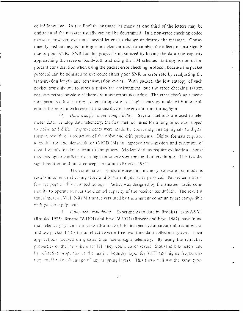
Figure 15. Elevation Radiation Pattern of the Unbalanced Hybrid Dipole (Sha s,
1973
4. Antenna
The antenna used for the shore station is a high gain, narrow beam, vertically
polarized antenna by Cushcraft Corporation of Manchester, NIl, model 230 WB
Boomer (Figure 17). Specifications for the antenna are listed in the Appendix J. I his
antenna directs its pattern in a narrow horizontal beam down the line-of-sight of thenmorings to be monitored ofT the Point Sur, CA, transect (Figure 5). -fhe antenna is
constructed of aluminum and stainless steel fasteners and has a total weight of 22
pounds. ' he antenna is subject to salt water corrosion, but considering its cost (S260),
34

9 _________________________________________MAN_____
Fi-mire 16. initial Telemetry Experiment Bet~een Point Sur. CA. and Research
Vessel Point Stir: The initial telemecti-v test used an I CON 2S\. Paic-
Comml TN'C 220 and a Conmmodore comiputer S\stemi.
a ! 11C rcpliced , '~nli"v Or for echII moor1-ine- cvLIe. ReCu2lar anitenna replacement
AlPoP-t SLIr. the C'oast Guard must a uthorizc an\ installations on the tower.
Ike- Pr k ranger at Pl'ilfc r BiL' Suir State Park. Bliz Sur, CA, should also be contacted to
cnsurc tha,,t the,, p-roposecd antenina struIcture Is not offknrsive inI appearanc. The tower
~ iiutrt)i Fic -urc I S. Prellivinary IiTsjuIiiS indicated that both the Coa-st Guar11d
111J theC P 'SrvILe \kill suqrort this projeLt.
5.Site Selection
P ;.t ur.( . '. isselcted as the sIte 1()r the shore ,tation. bnecause it is nearly
():In eL Wee In !'L1eue 3. urim, the: two testin p)- eriod, access,

5...
Figure 17. Shore Station Atenna: The antenna is a high gain, vertically
polarized antenna. It is a light weight, low cost, aluminum structure.
Salt air corrosion will require annual replacement in order to insure
maximum performance. Specifications are listed in Appendix L.
was gained to Point Sur, from the Pfeiffer Big Sur park service. Liaison was established
with the head ranger, (Tex Ritter) and the Coast Guard, Monterey, CA, to secure site
usage on the tower. Site usage is highly probable for a future installation, but must first
be cleared with the Coast Guard Engineering Section in Alameda, CA. Clearance re-
quires forwarding the telemetry system specifications indicating type of antenna, antenna
gain, antenna beam heading, proposed position on the tower, transceiver power and
frequency, to the Coast Guard via the park ranger. The assignment of an operating
frequency has taken eight nonths and has been the longest lead time requirement for
this project.
This site should provide satisfactory operation out to point P3 in Figure 5. If,
for some reason, this site is unsatisfactory, the foot hills behind Point Sur could poten-
36
~ In
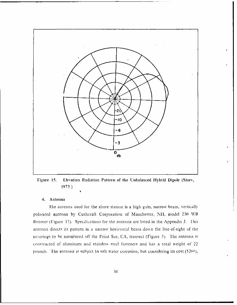
I 211 I~ Point Suir. CA. IoN%cr: '11w is a t\\ o section photo of the Point SurI jaj cieaanc~ hi oah the ('oa,, Guard and the Park Ser\ ic
StO ") o 1,;,1, e t! e a ri"tcIenIna i I "t at io. Installlation point is
Ii. . ili '>te i\ aIt 1211() itl 01n 1ittIe Riverl Illil (I Venre 19). whiCh is mIuch)
at hctor linc-of-sight Jintanc to the rnoorine. Qiurm 141
&~>iV A p\ wwo;;m ranue betweenC t\wO anensM~Inch IIUltCS the
PccK> it and I ilt~ Ri~cr Ihil at 121)() It
\I ! t a'>':cc.1 ~ ' ca~a'.e beor I" L'nle Ctio cill

Venturo 7Rocks~
-f II
Yj I I
* IM
000
4.4
S .'
Floint Sur8 le
Sur Rok * *. mole's
Fiue19. Topographic Map of Point Suir and Little River 11ill: 1The MontereyCounty communications site on Little River 11li11 is a possible shore
station back-uip site for monitoring the mooring transect.

III. ENVIRONMNENTAL CONSIDERATIONS
A. METEOROLOGICAL CONSIDERATIONS
1. Electromagnetic propagation
1 elernetr,, operations in the VHIFI spectrum are subject to three conditions wshich
cmitro1 tuie raii-e 01 a propagated signat: j) ouulaarv layer gradients, 21) trapping anu
l, ine-of-si~ht. Line-of-sight is the commonly selected propagation mode between two
antennas in twe VI I F sp,-etrurn and is the mode this project will use. The other two
modes are atmospherically cui.:rolled, but can affiect line-of-sight propagation by creat-
min ultipath conditions resuilting fromn bour iarv laxer refraction interferenice and canl
potenmt: !hamper lFM% reception.- The1 Marine boundary la-yer canI also effectlvely e\-tenid tile radio horizon by providling conditions of super refr-action (lrapningx) Atno-
, -icra vesi andpassee of fronital weather Syst ems provide unusu.ally lon1g
prora I ti :r luIrrp1L.
'Fi, mnost reli'able VI IF upagriUn1I- I- l; ne-lIht via thle free spaceL
tran1w~son lth Onl1y Cases Of' sub11-refraction, at the edges of' the free space traiis-
rnjss7_in path, will1 reduce pr-opagatin conditions. Atmi-ospheric index of refractin 0V)
is a func(tionI of, .hsulu:e tempera tar-e (T), pressure n in b) and mnoisture Content ~
and, I,, c\pres ,cd inI the form:
N = 7T.6(P/fl- + 3. 71 x R)~ I-
Thew -ria radhint Of, X I" fInI terms ofl q istead of c where q 0.622c in gin kg anid
is the waiter vapor riine ratio):
t1.Ydtil = cif(dlItdhl + ci(dqldl + fd/h
C-I -- .
TFhe classification scheme developed for the Navys' Integrated RefractiVe
LfeCts PredictionI System (I REPS) IclassifIcation defines four refraction conditions using
dNdl
S~ ~~~J !h -:-rY 0azdNdiA( per Liii re'duIced propagation)
39

" Xurtnal (standard atmosphere) dN dh = 0 to -79 per km (normal propagation)
* Supcr rcfi-actii dN dh = -719 to -157 per km (increased propagation)
* rarring d\ dlh < -157 per km (greatly increased propagation)
Figure 2U illustrates the I REPS classification.
b. BoundarY Iaier
T-he marine boundary laver has a large moisture flux at the surface which
.. .s L i. resulting in laiger q grau,,ics near the surTace and
smaller temperature gradients. The reduced miixing in the boundry layer causes larger
gradients. The moisture flux from the ocean to the atmosphere is essentially confined
to the thickness of the atmospheric boundary layer, which may range from a few hun-
dred meters to several thousand meters. Refractive conditions exist where the q gradi-
ents are larCe at the suLI:ce and decrL,_:,inc with heiCht. Weather anomalies cause
changes to the relaction conditions. Cold, dry, continental air moving offlhore over a
warm ocean produces the most intense evaporative moisture fluxes. When tnis situationl
is accompanied by a stable bOLndair la er. the vertical turbulent mixing is suppressed.
which favors trapping of propagating electomacnetic waves. Warm moist air flowin
ovcr cold vater can provide favorable propagation if lbg is produceu 10 tile surface
',er. In such cases, the lower atmosphere is completely saturated, wiile the
.r above ay be consiue,,a!v dry,, resultiLe in sliarp gradients of q and potentiallyl
stro:nc retra! -ticn. 'Brooks. 19S4)
lie marin,e boundary layer conditions off of Point Sui. CA, sclruii cup-
ports a sub-refiaction condition, l1owever, a long tern study is needed to invc-igate
the iniluerice of mulipath refraction conditions \\ hen trapping conditions exist. Line-
of' silit com:ntnications can be expected under all otlher conditions. The height of the
antenna on Point Sur 13S0 ft). will usualxv be in the marine boundary la\er. but the al-
ternate sh ore static: site at Little River I fill with an elevation of 12(00 ft. may be subject
to cross bounldr% propagation conditions. A decision to use Little River I 11 will re-
quire investigation into the potential propagation limitations, i.e. Little River 1lill may
not receive the buoy signal under strong surface ducting conditions.
c. Trapping
Trapping (or ducting) conditions exist when tle dN dh < -157 per km and
this laxer is th,k enough to trap the frequency of interest. This condition occasionally
occurs for the I-40-151 NI I l/ frequent) at Point Sur. when a frontal passage develops a
trappningc laxer crdient condition 1dN d\ - -157) over a vertical distance grcater th' i,
4Ir

Subrolracton pr 0
• / // Normal
Su er-refractlon
Vigure 20}. IREPS Classification of EN I propagation: Propagation of PF in the
VII]~t spcLIM is inlflUece):d by_ boundary layer gradienits, which chiange
the rcti-active index and influence propagaLtion.
IS5I m. While it can significantly enhance SNR. it may also perniit long range propa-
cation of interference to actually reduce the SNR. Iliming of telemetry in the morning
,ica tI iezI -- 6 'ir tclrneratures are closcr together than in the afternoon) will mini-
inize the condition 1avorable for trapping development. ligure 21 from Miller (1986),
illustrates ducting vs frequency and refraction index classifications.
2. The effect of isind stress on the buoy antenna pattern
th ' telemetry system will transmit once per day, preferably under calm condi-
tions. (oasta i wiids were studied for diurnal variability at Moss Landing, CA and
Monterey, CA, using 30 mililte averaged data recorded for the year 1988. The data
came from niorthlv reports issued by Monterey Bay Aquarium and Moss Landing Ma-
rine Laboratories Monthly Weather and Oceanographic Summary. lihe weekly plots
of the 30 minute averaged values of air tenipcrature, solar irfadiance, wind direction,
wind speed and barometric piessure are shown in figure 22. 13% over-laying eight weeks
of plots, the diurnal variations bccain ex idctlt. I his over-laying technique was applied
41

50
300
200
S100
432 MHz003MH
100 200 Soo 400 500 $00 To00 Boo 9100
FREOUENCY ( MHzl
Ifigure 21. Tlrapping Ns Freqluency. (Miller, 1986): Tlhis graph illustrates the re-
lationship of' the trapping layer thickness to the frequency which can
be tr-apped.
freqc eason in 1988, and a diurnal pattern for coastal meteorology becamne clear and
i l~aaceried n igre22. What is seen is that the nearshcre wind (and other pa-
rameters) had a typical and predictable pattern (Figure 23) indicating winds are a minil-
11IL11 at runrise and tmaxinuun in the late afternoon. 'Ihits same observation was rioted
h\ Beardsley eltal. (19871) in his description of the marine boundary lay+er and atmo-
sphecric conditions over a Northern California upwelling regi-on, Illis study depicts the
Salle diurnal wind speed, wind direction and time Of' tnaxinmums and ninrill1111.
Beardsley' (!1987) showved that this diurnal aflecct was a coastal phenomenon, and the
diurnal influence becomes Nery weak at about 35 kmi out to sea.
These studies indicate a wind speed nmininium n~ear sunrise out to about 10 11iles
cellshore, which should provide the optimium conditions for data telemectry'. For a
mooring transect. such as at Point Stir, the near shore telemetry systemi would be timed
to transmilt at sunriseC. 'Ilie more seaward telemetry systems can also be progran-aned to
transnit at sunset or at any other time of the daN .
B. OCEANOGRAPIC CONSIDERAI1IONS
1. Wave height effects on buoy antenna pattern
'Ilhe way in which ocean motion infliccs a Iloating vertica! antenna are very
difficult to predict. Buoy motion I-a result of ind and wave action on the antenna and
,2

~A
'° t A
11-
lo
I 2 3 4 B M r M
P'lot s: 'Ile plot on the lef't iq a sample ofa weck ofthe year From the
\Ionltrcy Ila, Aquatrium anud \Ios Landig Mamuic La'oratorics
Mlontlk W'c thcr and ()ccanopraphic Summary and on tie righ1t is Z11
43

kix solar Wind wind Bftrmtr±GTeperatuzre IrradiAie speed Tiretian Pre IrI
I J i •
810
IS0
13 K 64
0A
0 12 24 124 0 12 24 0 12 24 0 12 24
Time of the Day
Figure 23. Typical Characteristic Curves of lonterey Coastal
M1eteorology: Curves wcre developed from the characteristic plot-
such as seen in I igure 22. I liese diurnal patterns where found to be
repetitive though out the Near. Ihe same sinilarity of the time scale,
wind speed and wind direction can be found in Bearsdslev et al., 19S7.
the local wave field can influence the interference pattern of direct and indirect RF
piopagation paths. Figure 15 shows the radiation pattern of the proposed unbalanced
hybrid dipole. "he parasitic stub influences current distiibution on the antenna (Snaw,
1973), but this particular design has not been tested over the ocean to see what influence
the ground plane of the ocean will have on a tilting antenna. Results of a s'aitic tilt test,
done between a shore station and a beach 52 kin away, are discussed in the next chapter.
Ihe tests verify that the hx brid dipole antenna can perform under tilting conditions
similar to those that may be experienced by wave and wind influences.
C. SURVIVABILJ] Y OF SURFACE BUOYS
1. Enironnient, shipping lanes arid fishermen
E:xperience with long-term survivability of moored buoys is not good (Briscoe
et al., 1985). A rc of. Cf I y -.ie 6 and the transect mooming site of I iguie 5 indicates
44

that O ver a IS() day de plo\vment. the survivability of a surfa±ce buoy can be questioned
~n.:b~ied n the Shiipping e~t aloneC. I 1sherniea also present hazards, but theirn~tzardsapi to both surfl.ce anid submnrd moorines. The main concern isthe Cha]iCe
nti of a f-I-ed, mloorine' At least with surf'ae buoys the fishermen avoid netting the
ni'ocr~nc. Suhrnired macmm>L,. how ever, are still subject to damnase. [or either case a
NVotice lo Mabriners is required. both to address the safety issues for the fishermen and the
Sur\ 11-lity Of' the" P10orins. The pop-up buoy design is a popular concept that has not
been SULCCessf1y1 deploNyed, but if' deployed it will avoid the surface shipping traffic anid
hazards ofl the surface env ironmient. It wvili not alleviate the fishermen problem.

IV. SYSTEM INTEGRATION AND TESTING
A. BUOY MOUNTED EQUIPMENT
1. Electromagnetic compatibility (EMC)a. Computer to radio EMC
Electromagnetic compatibility ensures that the electromagnetic radiation
caused by oscillators, pulsing circuits and system non-linearity are isolated from other
equipment. The most graphic example is radiation from the computer clock
which is a 4 NI Iz sqLare wave signal. To reproduce the 4 MHz square wave requires
a broad spectrum of Fourier harmonics. but if the 4 Ml Iz clock produced a sine wave.
on!\ thle ; Nltz freN.Iency would be present.
As the proposed system consists of integrations of other equipment designs.interfcrence requiriN correction can occur. The standard ENIC discipline procedures to
correct probM-en are:
* Shielding (fully enclose equipment in metal containers)
' ii.ri e provide a low impedance to ground to ofi--iding radiation)
• l'6ysical Separation (relocate equipment and enclosures)
* Circuit I)esigri (c omponent arranzcment For minimur Interaction)
* lrcqueicy :Assignnent (do not operate on related harmonics)
• Avoid conmmon signal and power grounds (power flow noise interference)
Ilese e NI C disciplines have limitations:
• Practical filter linitations
• Space limitations
* I)esiCn trade-offs
• Available frequency
If poor E NIC exists alter prudent procedures are used. then a measurement methodology
is reqair"ed to olt-iah a spectrUn signature.
I ni'ial sxtea integration of the T14. INC and ICOM indicated that the
l-A and the I NC iccrated noise which was reduced by putting the ICONI in a sepa-
rate crclovure. I mprovenmcnlt in the ICOM's sensitivity was obtained using a preampli-
fier between the I(C(NI and the antenna. Sstcii design limitations required the
orcar ,i)!: her t'', nCmuntd,t wi11 the I( ONI and not at the a ntcnia. The I(()NI's per-
469
formance was definitely improved, but when operated with the TT4 and TNC, the per-
formance margin disappeared.
b. Methods to overcome EMC
Poor EMC problems existed and are eliminated by enclosing the TNC and
TT4 in one enclosure and the ICOM and preamplifier in another enclosure. Figure 24
illustrates the two enclosures, with the larger enclosure containing the TNC and TT4.
On both enclosures, all electrical connections (except the antenna) were passed through
feed-throuoh terminals. Each terminal is fitted with very short lead capacitors rated at
.05 pf to short any 4.9152 Mltz oscillator signals from both the TNC and TT4 micro-
processor oscillators and a 100 pf to short to ground any 143.675 Mtlz harmonics.
Fiure 25 illustrates the point that capacitors used at one frequency can behave quite
diHfercntly at higher frequencies. Theoretically, the .05 Pf should short all signals from
IMtz on up, but at 143 Mfz the leads to the capacitor develop inductive reactance
and remove the low impedance to ground. The 100 pf capacitor restores the low
impedance to ground for 143.675 Mlt/ harmonics. Additional shielding precautions
xvhere taken to isolate noise sources by securine the enclosure lids with sheet metal
screws every 3 4 inches and to cover all holes with copper adhesive tape. The end result
iS negcligible computer noise in the ICOMI, thus improving the ability to gain a margin
of signal excess.
2. PoN er distrihution
a. Battern s.riteis and capacities
The hattery systems are a critical element in dete ninig the size. weight,
and power handling limitations of each subsystem. The project has three subsystems
reuniring hattery power:
"1 14 and Aandcraa hydrophone
* Telenetry transceiver
* Underwater winch
The T-14 and h% drophone subsv stern requires continious battery power for
the dar;tion of the sys tern deployment. The current drain is averaged to 5 MA for the
114 and 3 MAI: for the htvdrophone. On thc conservative side, this subsystem requires
I0 NI.A continuous currcnt. which equates to 43 Anp Ilours (All) for a 6 month de-
plo.x mi.n t. the 114 'oltace req uirmcint is any value between 7 and 15 volts and the
J:>d,: }:,c \ o1a-,- re .lireicent is an value between 6 and 9 volts. ]ach s\stein has

Figure 24. EMC Protection Using Shield Materials: To ensure EMC, the TNC
and TT4 are enclosed together in the larger container, and the ICOM
and preamplifier are enclosed in the smaller container. Each electrical
connection is filtered to remove noise, all holes are are sealed and the
container lids are secured with sheet metal screws every 3 4 inch.
an internal volta - regulator, which permits battery voltage variations without affecting
sstem operation.
The telemctry transceiver subsystem has a power surging demand for less
th_,i 5 minutes per day Ior the deployment period. The current drain is maximum of 1.3
amps for transmit and 100 MA for receive. On the conservative side, this subsystem
rcquires 15 hours of power over a 6 month deployment. which equates to less than 20
AlI of' power. 'he power output of the transmitter section of the telemetry system is
- seCnIti, C to chames to the batter\ voltage. The higher the battery voltage during
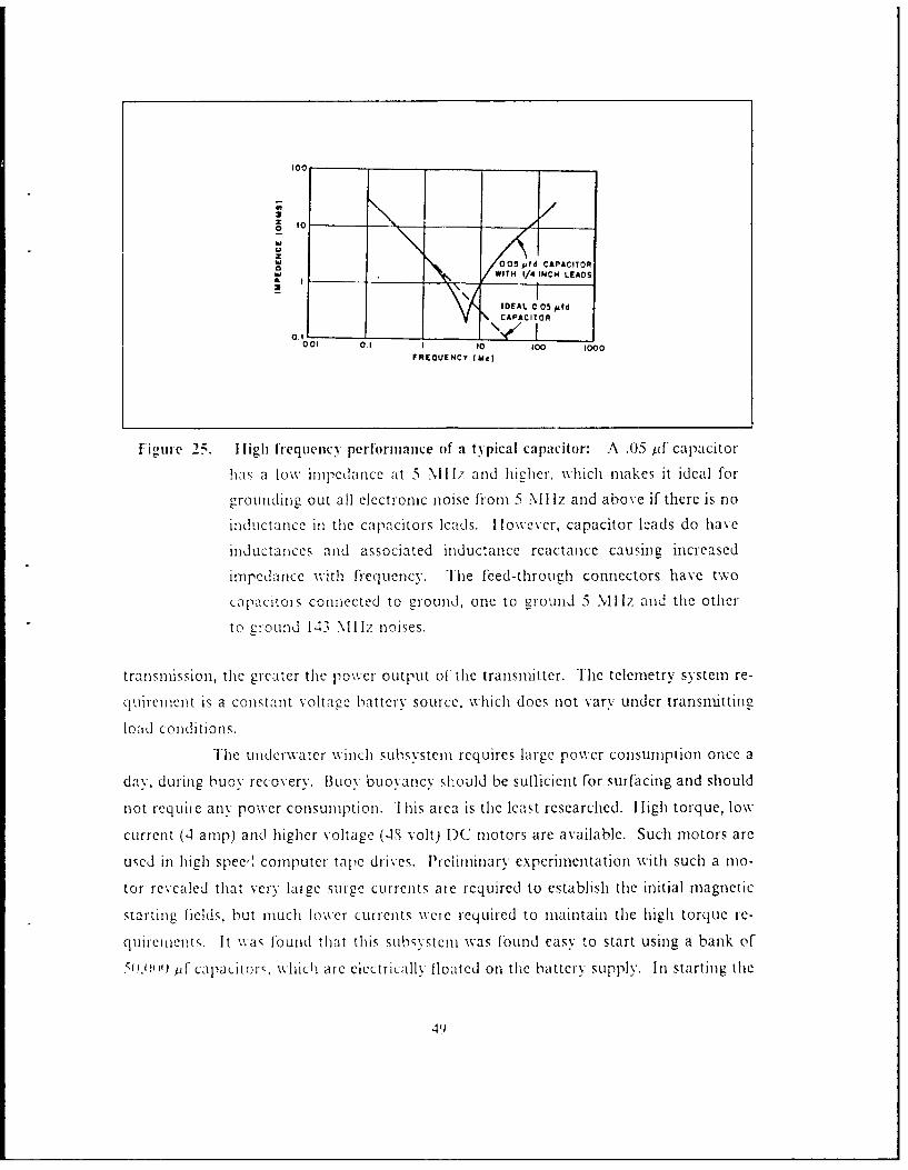
I00
z to_ _o
.
S05 fd CAPACITORWITH 1/4 INCH LEADS
IDEAL 0C05 dCAPACITOR
0.1 IL001 0.1 I 10 100 1000
FREOUENCY (Mc)
Figure 25. ligh frequency performance of a typical capacitor: A .05 pf capacitor
has a low impedance at 5 .i II. and higher, which makes it ideal for
grounding out all electronic noise from 5 %I liz and above if there is no
inductance iII the capacitors leads. I lowever, capacitor lzads do have
inductances and associated inductance reactance causing increased
impedance with frequency. lhe feed-through connectors have two
capacitors connected to ground, one to ground 5 %Iliz and the other
to ground 143 Nllz noises.
transmission, the greater the power output of the transmitter. The telemetry system re-
quirement is a constant voltage battery source, which does not vary under transmitting
load conditions.
I-he underwater winch subsystem requires large power consumption once a
day. during buoy recovery. Buoy buoyancy should be suflicient for surfacing and should
not requiie any power consumption. 'l his area is the least researched. I ugh torque, low
current (4 amp) and higher voltage (4S volt) )C motors are available. Such motors are
used in high spec. computer tapie drives. Preliminary experimentation with such a nio-
tor revealed that very large surge currents are required to establish the initial magnetic
starting fields, but much lower currents were required to maintain the high torque re-
quilrements. It wa, Found that this subsystem was found easy to start using a bank of
50.01 )) p f capacitor-, which are electrically floated on the battery supply. In starting the
49

motor, the bank of capacitors provided the needed surge current which reduced the de-
mand on the battery system, thus extending battery life.
b. Batterr characteris tics
The batteries selected are required to function at 5 degrees C, have a long
shelf life, operate in any position and have minimum gasing on discharge. These re-
quirements can be met by three types of batteries:
" Alkaline-Mananese Dioxide (AMD)
* Lithium-Sulfur-Dioxide (LSD)
" Sealed Lead-Acid (SLA)
Each of these batteries have limitations which would eliminate exclusive selection for all
three subsystems. Table 3 on page 51 shows the physical parameters of the three types
of batteries.
Table 3. PHYSICAL PARAMETERS OF THE SELECTED PROJECT BAT-TERI ES.: Batterics \ere co1Mbined to equLate to a single 20 All sourceto provide comparison of cost. weight and size for equivalent battery ca-pacities.
AM D S.) SLA
Brand Duracell SI)XiG21) 12) Power SonicNa.-e PC926 Lternacell PS- 12200
12 to 6.4 14 12.3 to 11.8
61 oz 42 oz 2S2 ozweight
20 All 2 ci 49 ci 2 isite
Cost S14 slo S7O(cct I
FiVure 26 illustrates the discharge characteristics for each type of battcry.
The ANID can handle the low current-drain subsystem (TT4 and
h. drophone , which is able to operate under varying voltage levels. The LSD can handle
the constant voltage requirements of the tclemetry system and has the added advantage
of light weight and small size making it ideal for the pop-up buoy. But these batteries
are cxpensive and require special handling to prevent explosions which result from
production when operated at excessively high discharge rates. The Sl.A
50

12.8 ____
12.0
11.2_ _
10.4wU
~9.6I-o 8.8
6.4
0 20 40 60 80 100 120 140SERVICE HOURS
Figure 26. Discharge characteristics of the selected project b~atteries:: The AMID
haiq a large voltaige drop under moderate baittery loading. 'llhe LSI)
malitais a constant load voltage unitil discliareed. 'I lie S LA has a
S1l21ht load voltagze drop dairing battcry l11'C
Can1 han1dle the high1 Current requircnmcnts of the winch subsystem, providecd that suml'-
Milnt huovanZ11c% Is available to support the batteries. Th1 wi inch. subsystem batter-y de-
man 11d has not been calcula ted, but It is expcted to be at least 100) A il. Th is w ouid
exclude tihe I-SI due to cost and size of the potenitial explosive hazard.
Design i ntergration of a prototx pc system) will require experimentation to
con~qildcr the LSD f) r the -1 14, hivdrophone and telemetry subsysr-tem1s.
3. Antemn
a. fVei-tial po/aiation and wave motion
Thecre are two primary designs lor antenna polarization: vertical and horl-
7011ta . F ach (le1sign can be onidirectional or directional. An omni11directional-vertical
p~lridawnan has1 a1 Pattern Vlic funclins uniforinally around the horizon.- A
51

directional-vertical antenna was not considered because the antenna requires streering
to niaintain an antenna patteIn toward, the shore station.
H orizontal oinnidectional radiation patterns are developed using vertically
polarized antennas which require vertical radiating elements. The omnidirectional gain
of a vertical antenna is increased by selection of antenna height, the number of-stacked
antenna elements and the relative distane to a real or artifical ground plane (Figure 13,
Ficure 14 and -isure 15). The desien used is illustrated in Fiaure 13.
A critical element in buoy antenna systems is the ability of the antenna to
function while under the influences of wave motion and wind stresses. Antenna
polarization between two sttations should be the same, but as a result of wave motion
and wind stre-ses, the pa riz"O /Lio1 of the buoy antcnn1a is constantly changing. When
antennas.... are cross n 'c,1 ,9, derees off axivs to each other4 a cain reduction of as
much as 2( db can occur. To compensate for the signal fluctoations. the antenna and
buOy 1lotation s'ruIctur-e Ist be designed to limit the eflccts of wave motion and wind
strc,,,,. Ie totei sx c:nI lte)ration concept is to maiximize data throughput using1
redundent error checking transmissions, signal excess to overcome antenna motion and
buoy de i,_n to a1:1,1: v. ,C Ctiolon eflects.
B. SHORE STATION
IIhe shore station at Point Sur. CA. was selected because of its postion. elevation.
access and a% al,> f C!,-, tical power. Point Sur is on a ine with the transect U ig-
UrC 5) and hias a see 1,, 2el clevation of 3.10 feet. Being on a line to the transect permits
a vertially poiarl/ed dircctiO',l altel C I igure 17) to be used to intercept buoy
t:anmissions, an:d ,;it. Vie eevation. the transmissions can achieve a range to just be-
vond 3f NI. Ihe annc na tower at Point Sur (Figure 1S can provide an additional
-P, to (f, feet ofelevation to the antenna installation. No modifications are required for
t11C pa-ckct teienietr\ sno e ration equipment. The installation in Figure 16 was not
subject to F.CNI probkc::, but if equipment and computer types arc mixed, some t(_ \1
may occur rC(1ir;n ,_ ' Ip ni, of equipment. Interconnections of equipment aresuf entlv, detailed i:n : e." c ,n~ipinent documents. Tlie antenna installation will require
periodic ciicv: . fr c> ':,. structural a!ignment and electrical measurements of dWe
voitazc tar'd: ,va. c y. ,VSWAR,. because of the salt, f.e and wind environment at
52

C. TESTING
1. Buoy to Point Sur shore station
Two testing periods were conducted L, tween the Point Sur, CA, and the R V
Point Sur. Each testing period involved the R. V Point Sur operating along the transect
line (Figure 5). The first test involved determining which propagation path should be
u~. ]The second testing period (a few months later) involved an in-water test of the
buoy package. using the best propagation path dctermined from the first test.
a. Testing propagation modes
This first at sea test was designed to find out which mode of propagation
(direct or surface ducting) could achieve a 52 km telemetry path over the water. This
test used three packet stations: 1) an automatic response to query buoy package on the
R V Point Sur (package physically attached to the ship with the antenna at 15 feet above
sea leveb. 21 an autonmatic resnonse to nuerv beach mounted package at 10 feet above
sea level, next to Point Sur, CA, and 3) the master query station (Figure 16) at 360 fct
above sea le\el on Point Sur, CA. From the master query station several connection
mode cere possible Ior testing the ahility of each station to connecL to the other
station,:
* master to buoV
* master to beach
* master tn buoe vli beach
* master to beach via buov
Additionally. the buoy aind beach stations where programmed to send 30 inute beacon
transiissions as an additional moToitor routine (the beach unit sent its beacon via the
buoy to the master station). Connections and beacons were recorded at the master
station and were stored in the buoy and beach TNCs. The stored data from the buo\
and beach T\Cs were time stamped at the time of each connection, which allowed fixing
thc loss of signal to the support ships track.
Test results found that the beach station was limited to line-of-sioht (20 km)
and no boundrx layer propagation at sea level existed for the 145 MljZ signal. The
propagation foin the master station existed out to 75 km, with some message
retransmission required. The test was carried out using a modified version of Figure 8.
The buoy sx stem did not have the pre-arnplifier and the transmitter was selected to op-
erate at a low power setting of L.5 watts (high power setting is 5 watts). The low power
"etting was used a" a furthcr sensitivit _cst on the system limitations. The final design
53

will be set on high power to insure signal excess. This test demonstrated that packet
telemetry can be used to send data from the transect line to the Point Sur shore station.
Atmospheric conditions during both testing periods had normal electromagnetic refrac-
tion conditions. The antenna test installations are shown in Appendix M.
b. Testing the buoy in-water
This testing period was used to find out how an integated buoy package
night function at sea and what affects the the seas would have on the antenna system.
The buoy system package was the same as the first at sea test, but it was packaged for
in-water operations. Results indicated the following:
" Vertical buoy stablitv is important to minimize antenna motion.
" TNC preprogrammed transmission lengths should be short to reduce data errorlosses duC to antenna motion.
• Buoy system programs needed improved automation timing to prevent the systemfrom getting locked-up in a progranmming loop.
• Improve the buoys transmitter by operating on high power.
• Install a preamplifier to improve weak signal reception.
2. Antennas
Testing of the antennas focused on the evaluation of the buoy antenna
prcformance at 52 km over water and under the influence of antenna tilt causing cross
polt~ riia ion ca n red 2ctions.
a. Tilt te.sting of'buoY" antenna at 52 km
This was the critical test to find out what limitations exist, which will limit
the application of this thesis concept.
The last at sea test resulted in re-evaluation of the receiver sensitivity. The
receiver sensitivity was tested under two conditions: 1) in its normal configuration and
2) with r. commerical preamplifier attached. The test was performed using a
RACAL-DANA ()hS2P SN-4192, rf signal gencrator. Figure 27 illustrates the results of
the receiver sensitivity tests. The improved sensitivity (Figure 27) using the preamplifier
also improved reception of computer noise from the TNC and the T,4. The LNIC
procedures discussed earlier were required to improve weak signal enhancement provided
by the preamplificr.
Additional opportunities for at-sea testing of the improvements to the buoy
transccivcr wcrc not available. To test the improvements, two alternative tests were
dveclopcd: I to test the buoy sx stem oer 52 km of water between 2 land stations and
54

LL
- H
C21
C! 00
C14 ; C;C; H
0110DE)U")V\.<Ll.V -IA-TXD IN-IV DS
Figure 27. ICOI\I receiher iuprieiient using a preamplifier: The addition of the
preamplifier improved the signal response and also the susceptabilitY
to cectroinagnctic initerfmrence from the INC and 11-4.

2) to test the buoy system under different antenna tilt conditions to simulate buoy mo-
tion at 52 kmll ra " between these stations.
Tests were conducted using the antenna in Figure 17, which was at an ele-
vation of 320 feet above sea level, on a radio tower at the Naval Postgraduate School
housin, area in Monterey. CA. Appendix N shows the antenna installation at NPS.
The equipment configuration is shown in Figure 8. Additionally, the TNC and TT4
package and the transceiver package (Figure 24) were connected using the intended 150
feet (Kevlar reinforced cable with 4-28 gage wires) underwater winch cable. The buoy
package was operated from Davenport Landing, which is a beach 52 km over water from
Monterey. CA. The shore station equipment, in Monterey. was programmed to ac-
knowkledgc the buoy in l)avenport, send a preprogranmed message (which provide time
to measure tie signal strcnei: in Davenport. CA) and then autonatically disconnect
iron, Davenpor:. When power was applied to the bum- (in Davenport), the buoy would
tran-mt a connect re cjest to Montere': :.,- seconds. Once the buoy was con-
nec'zcd a reaine of the SNR tap (Figure 12 %%as taken. The buoy antenna was cle-
c On a 6 foot pole. At the beach the anten na was tilted to the indicated directionl
and angdes in lb: --. I)uine cach 15 second interx al a reading\ was taken froim the
S\ .1 tap and ,as rouged in Tabic 4, and the antenna was repositioned fOr the next
rcadIn,. Irom Table 4 the average of ad! the rcadirngs was 1.402 volts with maximum
and niminium rca d a -Src wlihi 4" & of the average. Comparin, the SNR tap
rc ;c: ,to tFigure 2- indicated that sufflcient .xess sig,'nal eximsts over a 52 km path
O\c l \va tcr when titc pica!plifier is connected. This test indicated that the received
signal at tIme antenna \vas about 1 microvolt. Without the preamplifier, the I microvolt
i'ra; would onl provide about .13 volts at the SNR tap with the result of insu1kicit
signal to drive the TNC. Readings at the Monterey site also indicated that a full scale
sien, excess was bei'rw receved.
5

Table 4. RESULTS OF TILT TEST OF BUOY ANTENNA.: The values recordedare thc %olta'c rcdin_' taken from the SNR tap shown in Figure 12. andth s nu.e ol the \a~ues are shown in FIgure 2".
'llI LI STLB LB SIl .B S-1 1B STUB)I Rli("II\ A"GII I OWARD RICI IT AWAY lIT
\ertiKi 0) 1.-4( 1.52 1.50 1.50)1() 1.4O 1.5O 1.51 1.51Norh2 1.-1 1.415 1. 1.41
North135 1.43 1.47 1.43 1.465(_ 1.39 1.44 1.42 1.45
I 1.49 1.4) 57 I.4)
2___ 1.4 1.51 1 . -
1', I.A) I 1.47 I , 1 .43
I "1 ..5 )
2__ t 1.4 1) 1. 1 -5 -_ _
l't 1.45 1.46 1'5 1 1.45
1" ! 1.5 1 1.4) 1.-;I 1.43 1.4- 1 .4o 1.41
1\ Z' ' "A 15 1.w1
2' 1.' 1= 52 1.-'' 1.52,33I 1 .4 1..'- 1.)1.'1,, I.-N 1.441 I 1.5 1.52
2' I 1-, Ij 1______________ { 1.5
"B" { ' ) 3 1."" 1.-1 1.51'
1,___ __ __ 1.4', i 1.5 .-_______ 1.52_____
I, , 1.3)15 .( 1452_________ 1. - 1.4' 1.4, l.3>,____ ,_____ 1.________, _ 1 ..4 .__________ .___________
Souh,>:2' 1.5'' I.' .5 1.51
!. ________, 1.__,_ 1 .1.: 1.4w. .________
_____,, _ I <.5 1.45 1.ii.1
_______.5 ____ 1.41 1.2'' .12

3. Acoustic link (Aanderaa Instruments Inc.)
a. Te% tin-' acous tic linkl error- vate
The the,-t that d~ata could be transferred fr-om a recording current meter to a
remoce hydrop!nnc lead to the idea of' telemetry transmissions to shore. This thesis has
demonstra ted that Ww 'Ad oru'w .5i(,9IdI.5 can be transmiitted error-f'ree back to a
shore stat~cn. U nfort[Unatelv. the Aanderma Acoustic Linue was not designed to be a
rc.iah,-Il and error te acoustic: laiR For passine, data for more than about NO(i( meters in
water. The result is qn error-free tclcetrpv systern suppoitinig an eror-prone acoustic
link.
Thlt ;\ansieraa :\coustic l ink transducer model 2247 S\ 426 was tested o!T
Qne at IPoWm Suor, Q:\ at the tranwnet point P3 fRon, the it V Poit Sir. The ce'xc
ixtwas set vi zo fhi P:dhe Andu tos of the acousticln 11 'lie testuedaR UNI Zt r-
co:0 u rrclIT meter ruILh WAS attached to the cL.oc of' a (CID. 'Ihle czgc wvas lowered
Oo : th V ida and .O ' mode to ;y~ c~ dept! c' intlol for the, RG NI . ilhcoc
1: a,')'_' he ("11) wijnch e -i. vhlei ih neitis :i::->
heyacen the R(Al n d . t n aue and pro vided an ability\ to calculate -!I,, le net h
:>a 1--a I he )'P ylorat1 Loded MOcaK sienal. iae on, M NIN to the
h rJo pi onc. a"us do~ u . tw ic T114 antd the pro,-,ramn in :\ppcnsli \ G.
131 MOOM t ch 11roohoac Lt S fl\CtUS 1b)COW 1he VUTIOCe ald I ', ci
theRN' ~ uet rpeated depth J~oc.that the error liee, acous~ic
li'. r. o. cc nwy or lo \ heond 0) nywI trv. a full reord could not be a
lV, I 10: U a r iaoc Inmtin 11 0 od ted a stiniar test, but used
inanodcrr .k 'CL! . 'q m 'a' he resuls 'ac so nila r. e\ccp-t that t he, e\ -
pce:eOemcr ma ri, !iec amtinted the mrmo rates to the synclh pulise irorV
' a e pt S"tt \ ILn is not u~aflu! fir set: Os,;
I i,_' !1-jaotV thalt 0LCured UsinL' :\1':deraa deck unit and
0 N (_!n iHe reduced bn usine- the error eh 'I')-p
'n 1 1 11, '' ms 'te a in 'II BIASIC for procranoi e\Ccau!iCn onl the
I I it o 1incied a. dpronide'd a simple error lqiii

START
SET VARIABLES
rigure 28. Block ~~ diara offeporm-KchdcdsteAneraaosi us
duraion Ode.ON
To enure wat d t asst adwe h rosocrd h 1 eoprogram~ ~~~" waYeeopdt EnSetmgseenendrjcouo-eunenie
14K I nis rieesanoupt ro hehDROPhoe e fky
stringTIM whichE pti)2. SiECotasfl~* ~ ~ ~ I ( 0i-nel1 efrec
* Ill ~ol140*~~~I (OUT nef I e'~eal
50 H YE 0 159N

* 1001I001111
0 Channel 3 Conductivity
* Channel 4 Pressure
ON) 1I lO0
• Channel 5 Vector Direction
o Channel 6 Vector Speed
0 04))) 4 1 1i
0 Lnd of Record
o Time i 0- -00 Rcf data is 1 1 So
The lw-bit binary word is read from the least significant digit (LSD) on the
left to the most siznificant JiNit ISD) on the right. The record is stopped on the 61st
bit and the time and date is recorded. This program is not a cure, only an improvement.
I iCIenr", \, oc an Ci proved Icoust ic link.
c. Proposed alternative to the acoustic link
The Aardcra' ,C.IS has an alternative source for sending data by using
the 2994 ciecirical conneclor. The same pulse duration code sequence is sent to the
electriLal connector as well as the aeoustic transducer. Future designs should look to
fiber optic alternotives fr data tra nsfcr to the underwater winch. A rotating opticalcouphin joint may permit all the RCM Ss on an array to be linked by a single fiber optic
c :e,. vithout restrictin, the movement of the RCNIS.
6)

V. RECOMN1MENDATIONS AND CONCLUSIONS
A. RECOMMENDATIONS FOR ADDITIONAL THESIS TOPICS AT NPS:
* Continue mechanical engineering development of a pop-up buoy canister that willminimize antenna motion.
* Continue the mechanical engineering of the underwater winch.
" Continue the electronic engineering development of a reliable acoustic link, whichcan copy all transmissions from current meters on a vertical array.
" Continue telemetry environmental evaluation on the affects of trapping and multi-path interfeirrcnce influences, and collect statistical information on bit-error rateover a se~e:va months of telemetry operations.
" Continue to monitor the changes in telemetry equipment and take advantage oflowe cr power unis operating at higher baud rates, which would result in much lomk rtransmitter pover for the same length of transmitted data.
B. CONCItSIONS:
This thesis demonstrates that a VItF NI3tM packet telemetry systein, unde auto-
imtc, so,\varc control. i, a practical tool for near shore telemetry of in situ
oceanographic data. The availabilitv of this near real time data collection abihty offers
'he oppor.ilnity fbr researchers to Investigate and develop new methodologies 'or
howe,,suno. forecasting and hindcastino of near shore ocean current events. Near real
tine data collection from buoys means that researchers can collect high resolution
SS NI I, S and AVI I RR satcllite data at the time of an event. At present high resol-
ution s,talte data is removed (without storage) from source computers after 4S-72
ioars. Collected satellite data can be used to develop time series investigations before,
during and after a inooring event has been detected. thus supporting investigations of
undcrcurrcnt variabilit%. Data that is collected daily provides verification that a inorirng
is sid1 opcrat onaul, o-T rs the ability to conduct experiments of opportunity with other
researchers and may lead to the development of expendable moorings.
Ihe baic concepts of the automated packet telemetry systems are available from
nhohel tcchnaloeie . -e conmmunications industry is moving forward with higher
speed and lo-,wer povcr packet s- sterns. The basic system detailed here can be directly
apoled, to the uiie!er baud rates (960 baud). This svtcnl was developed asinx 1200)
had, telmcnetry. At tile n 9x00r T)( ) baud, on 1 8 of the transmittinge time is needed,
61I
which translates into reduced power consumption and smaller pop-up buoy canister de-
The objective of this thesis is to augment direct measurement technology by ad-
vancing the state-of-the-art in ocean data collection using near real time telemetry. This
thesis achieved the following:
* Demonlvrated that teleme'*.. c,.,pment :-.1 ,,,. !0.. ost, have !_,-w 'ower con-sumption and be small enough in size to support a pop-up buoy design.
" VILF NBFMI is the best modulation scheme for line-of-sight communications tonear shore buoys.
* Packet telemetry offers the best error checking protocol in the environments wherecommunications can be momentarily lost due to wave motion.
* Antenna height above ground is the most effective way to achieve longer line-of-sicht communications from shore stations, but not for buoy antennas.
Methods were developed to overcome electromagnetic compatiblity problems be-tweei computer svstenl and receivers, thus improving the ability to gain a margin0! inal cxcess.
SFvaluation, of various batteries where made to deterinine which battery can bestbc applied to each system;.
I)eveloprncnt of an improved error checking program to read the Aanderaahydrophoae recievcrs w,,, achieved.
" Development of a proglam for the ONSET Tattletale Model IV computer to au-tomate the collecting, measurng, storing and tclemetry of data was achieved.
Verification of, the desi,,n of the hyb rid dipole antenna to perform under conditionssimnilar to wave motion influences was made.
* Ivalahion of the Aandcraa Acoustic Link was completed and found to be thewatkest link to an etfecti\e data recusery system.
, desiLiated f-equency of 1.13.(,7 l l IZ was obtained from the N vv for a fivevear research period.
f stablis!,:e: of a liaison with the U.S. Coast Guard and the California Park Ser-vice was made to secure the use of the Point Sur. CA. site For testing.
IhIls thesis involved an ocean engineering investigation which provided an opportu-
nitv to investigate instrumentation applications to oceanography. ltonefullv this will
help advance state-of-the-art oceanography hardware and software towards three di-
mensioral modeling and prediction systenm.

APPENDIX A. IROJECT COSTS
UNIlS SERIAL NO, I I-EM UUSI1 07801 lLUM 1-28A 409.951 8804330 ASIRON pwr supply 69.951 09310 AS1RUN pwr supply 89.951 65033 ICOM-02Ar 279.991 09629848 Pre-amp ARR SP144VDb 109.951 09630848 Pre-amp ARR SP144VDG 109.951 Wall 12v pwr supply +or INC's 9.951 3001606 DIGIPAC I software 49.95
1 530 lattletale 4 computer w/Dev Kit 490.001 531 Tattletale 4 computer 395.00
1 532 lattletale 4 computer 395.001 7995 PAC-COMM TNC-22o 179.95I 7968b POG-CUMM 1NC-22u 179.951 M0199 FAC-CUMM MicroDower-2 INC 179.951 Lushcratt 2.U()WH antenna 239.95I 1t)uFr roll beldon 9-91- 5Y.954 -m-Dhenol 9913 "n" connectors 4. 3I I--blOFr roll KIevlar/2pair-28q cable 1t5. (-7 blocks ol syntactic +oam

APPENDIX B. SYSTEM PROGRAM WITH COMMENTS
START PROGRAM, THESIS. 0305 RTIME
'SET INTIAL VALUES10 D=:E0:F=0: L=0: M=O:N=0:P=0:W=0:X=O:G=0:C=0
'ENABLE CTRL-S AND CTRL-Q FOR TNC (CTRL-Q TIMEOUT IN 10SEC)14 XSHAKE 1000
'INITIALIZE SLEEP CYCLE16 SLEEP 0
WAIT FOR HYDROPHONE RECORD TO START20 IF PIN(13)-0 GOSUB 900
'RECYCLE POINT IN PROGRAMl FOR EACH RECORD WORD23 IF PIN(13)=0 GOSUB 10003D SLEEP 1
'CHECK IF 24 1OURS HAVE PASSED SINCE LAST TRANSMISSION35 Y=': I=: F=(Y/ 8640000)40 IF I=F GOTO 103
'RECYCLE AND WAiT FOR HYDROPHONE RECORD START50 GOT0 20
P~r'.M !NTER'UPT V1A CTL -C (TATTLETALE REQUIREMENT)! 6 s-f- P
'SEQUENCE I TO RECTGNIZE THE NEXT 24 HOUR PERIOD IN LINE 40105 i=1+l
GET START TIM!E; TURN ON RADIO AND TNC; CONNECT TO SHORE STATION110 J=60?(T(1)):K:T(0):PSET(15):SLEEP 500:PRINT"C KC3RL":SLEEP200
'CHECK TO SEE IF CONNECTED TO SHORE170 IF PIN(6)=O GOTO 190
'IF NOT CONNECTED, TRY AGAIN182 G=G+: Z=0184 SLEEP 100
185 IF G=10 GOTO 170186 IF G-=21 G 1.0187 IF G=30 GOT':)110
'DISCONNECT IF CA-.NT CONNECT TO SHORE188 IF G=31 GOTO 7>3189 GOTO 170
START TATTLETALE U.E Y OFF LOADI.9C A=j
(,4

200 FOR D= 1 TO W210 OTEXT A:ONERR 390220 NEXT D
RECORD TRANSMISSION TIME270 PRINT'TIME IS ',?(O):PRINT' ON ',?(4),'/',?(3),'/',?(5)
GUESSING ROUTINE FOR TATTLETALE TO SECURE RADIO AND TNC290 I=60"(?(i)):Y=?(0):Z=10*(I+Y)-10 c(J+K)310 Z=Z+700311 SLEEP Z
CHECK TO SEE IF ANY UNAKNOWLODGED PACKETS, IF SO WAIT AGAIN314 IF PIN(12)=O GOT0420
TERMINATE TNC DATA TRANSFER!PR:-f 03, 03, 03;
340 SLEEP 200
TNC DI SCONNECT350 FRINT"D"
C i= TO SEE IF SHORE DISCONNECTED3710 IF PIN(6)=i GOTO 390380 GOTO 311
'T'rEN OFF RADIO AND TNCPC R- 5
4"J SLE 3000
4I 104 20 G-:IF G=10 GOTO 390440 GOT0-3 10
,FYDCFr., DATA LOGGER ROUTINE START
910 Z=2: W=2:0=2:H=2: Q=2: R=2: S=2: T=2: U=2:V=2
'INITIAL TIMlE P1000 IF P=0 GOTO 1030I
'ALL OTHER P TIMES AFTER INTIAL P FRO:I TATTLETALE INITIAL TURN ON'ALS' SET BINARY 1 (RESET TO 0 IF PULSE IS 81MSEC IN LINE 1070)
150) B=1: L=:PL-
-FPLSE FFOM, HYDR....ONE > 2. 5SEC, THEN START OVER (BAD DATA CHECK)1020 IF P>230 GOTO 101)30 P=!r2 SEEP
TIMIE , USED IN NE=T WORD LOOP IN LINE 1005100 N:?
0
CHECK TO SEE IF HYDROPHONE IS STILL ON, IF SO SET BINARY 01.7 IF PI' 13)=O 0=0
1 o T S7
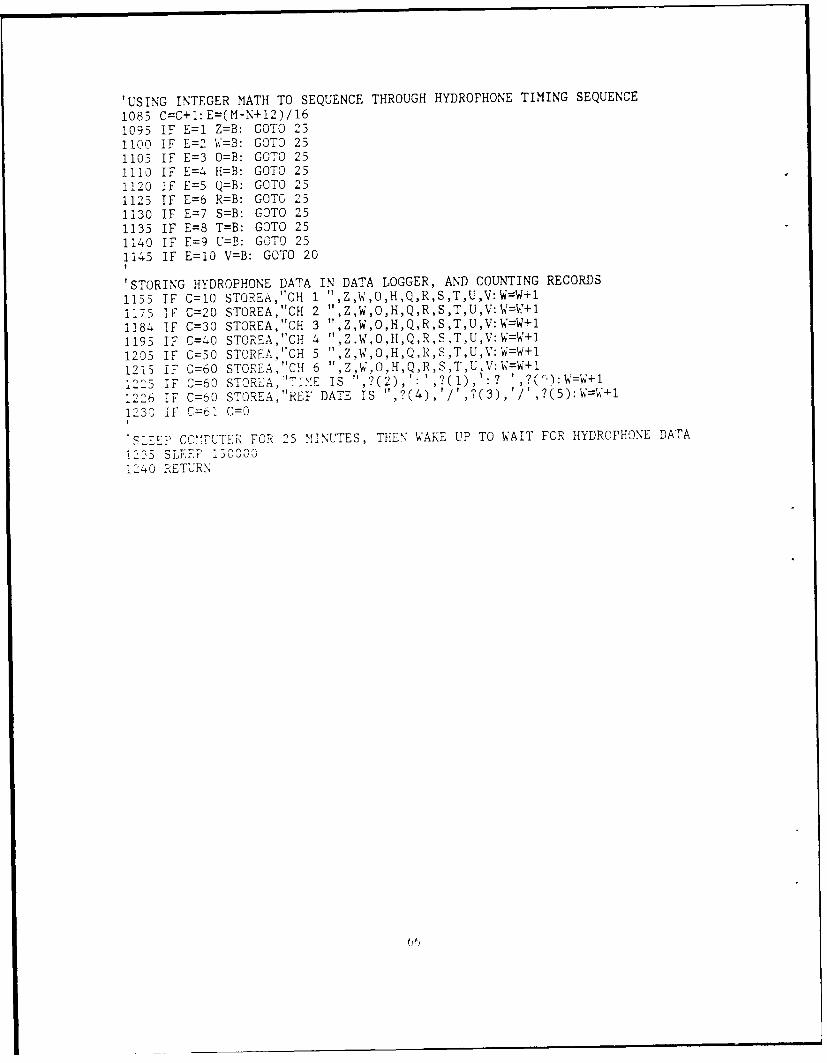
'USING INTEGER MATH TO SEQUENCE THROUGH HYDROPHONE TIMING SEQUENCE
1085 C=C+i:E=(M-N+12)/161095 IF E1l Z=B: GOTO 231100 IF E=2 W=B: GOTO 251103 IF E=3 0=B: GOTO 2-51110 IF E=4 H=B: GOTO 251120 IF E=5 Q=B: GOTO 251123 IF E=6 R=B: GOTO 251130 IF E=7 5=B: GOTO 2-51135 IF E=8 T=B: GOTO 251140 IF E=9 U=B: GOTO 251145 IF E=10 V=B: GOTO 20
'STORING HYDROPHONE DATA IN DATA LOGGER, AND COUNTING RECORDS
1155 IF C=10 STOREA,"CH 1 ',Z,W,O,1,Q,R,S,T,U,V:W=W+11175 IF C=20 STOREA ,",,CH 2 ",Z,W,O,H,Q,R,S,T,U,V:W=W-4-11184 IF C=30 STOREA,"CH 3 ",Z,W,O,H,Q,R,S,T,U,V:W=W+11195 IF C=40 STOREA,"CH 4 ",Z.W,O,H,Q,R.S,T,U,V:W=W+11205 IF C=50 STOREA,"CH 5 ",Z,W,O,H,Q,R,S9,T,U,V:W=W+11215 IF C=60 STOREA,"Cif 6 ",Z,W&,O,H,Q,R,STU,V:W=W+112 5 IF C=60 STOR--A , "TIM IS ",()' 1: ? ' 9(Th)W=W+1
1226 IF C=60 S .OREA,"REF DATE is ",()''?(3),'/t,?(5):W=W-'1
1230 IF C=61 G0o
'SEPCO"MPUTER FOR 25 MI1NU-TES, THEN WAKE UP TO WAIT FOR HYDROPHONE DATA1-35SLFP1]0O000
1L40 RETURN

APPENDIX C. 1-YDROPH-ONE PRINT PROGRAM
10W=0: Z0O: D=0: E0O: F=0: H=O: L=0: M=0: N=0: 0=0: P=0: Q0O: R=0: S=0: T=0: U0O: V=0
14 RTIM'E:C=0:N=?16 SLEEP 0'0 IF PTiN(13)=O GOSUB 100050 GOlID 15100 STOP
1000 IF P=0 GOTO 10301005 B=1 :P=L-Ml1020 IF P>250 GOTO 101030 P=11060 SLEEP 5
1070 IF PIN(13)=0 B=0
1.85 -C4-1:Dz)(C/ 10O,,10: E=C-D10-95 IF7 E1l z2B: iF E=2 W=P.:IF E=3 =B: IF E=4 H=B: IF E=5 Q=B1109O IF E=6 RB: IF E=7 5=B: IF E=8 T=B: IF E=9 U=B: IF E0O V=B1150 IF C=i PRINT"CEANNEL 1 REFERENCE"1175 1 C=19 PRINT Z W , 0 H,Q,R,S,T,U,V: PRINT: PRINT"CH!ANNEL 2 TEMlPERATURE",1175 IF c=20 PRINT ZW , O,H,Q,R,S,T,U,V: PRINT: PRINT"CHANNEL 3 CONDUCTIVITY"1184 IFr C=C RIN Z.W,O ,H ,Q, R,S ,T,U-,': PRINT: PRINT'tCHANNEL 4 PRESSURE"1193 1?' CJ -Li IT Z , ,0 ,H,Q,R,S,T,U,V: PRINT: PRINT"CIANNEL 5 VECTOR DIRECTION"1205 IF '-=30 PRINT Z,W,O,H,Q,R,S,T,U,7: PRINT: PRINT"CHANNEL 6 VECTOR SPEED"1215 IF C=60 PRINT L',W,O,H,Q,R ST U V:PRINT:PRINT"END OF RECORD"1225 IF C=60 PRINT"TIE IS "?2) ?(l1,': ? '9(0);
"12-6 - G= 60 P i%-,N T" REF DATE IS "?4,/ ?3,/ ?5123 IF C=61 \C0: PRINT: PRINTI.-K RTIRN
67

APPENDIX D. TEMPERATURE/RADIO CYCLE PROGRAM
10 XSHAKE 100020 RTIME30 X=0:G=O50 FORA=1 TO 10060 SLEEP 1070 STORE X,#2,CHAN(10)80 NEXT A90 GOTO 110
100 STOP110 J=60*(?(1)):K=?(0):PSET(15):SLEEP 500:PRINTr"C KC3RL":SLEEP200170 IF PIN(6)=0 GOTO 190182 G=G+1184 SLEEP 100185 IF G=20 GOTO 110186 IF G=30 GOTO 110187 IF G=30 GOTO110188 IF G=31 GOTO 390189 GOTO 170190 X=0:G=0200 FOR B= 1 TO 100210 A=TENP(G ET( X,, 2)220 A=A*(9/5)+320230 PRINT kA,A/10,' ,#.1,A%10;2 -I -F B'0i0=0 PRINT250 NEXT B2,0 PRINT'TIME IS ',?(2),': ,?(i)' ,?(O):PRINT' ON ',?(4),'/',?(3),'/',?(5)290 I6*?1)Y?0:=O(+)I*JK
310 Z=Z+700311 SLEEP Z314 IF PIN(12)=0 GOT0420330 PRINT 03, 03, 03;3- SLEEP 200350 PRINT"D"370 IF PIN(6)=1 GOTO 390380 GOTO 360390 PCLR1540 SLEEP 3000410 GOTO 20L20 G=G -I: IF G=10 GOTO 390
440 GOT0310

APPENDIX E. SYSTEM PROGRAM TO STORE DATA TEST
5 RT IME10 DO: EO: F=0: L0O: O: NO: PO: WO: XO: GO: C014 XSIHAKE 100016 SLE 020 IF PIN(13)=O G0508 90025 IF PIN(13)=0 GOSUB 100030 SLEEP 135 Y=?: 1=1: F(Y/8640000)40 IF I=F GOTO 10550 GOTO 20100 STOP1035 1=1+1110 J=60,V(11 ):K=?(01:PSET(15):SLEEP 500: PRINT"C KC3RL":SLEEP200170 IF PIN(o)=0 'GOTO 190182 G=G+1: Z=0184 SLEEP 100185 -IF G=10 GOTO 110186 IF G=20 GCTO 1110187 IF G=30 GOT0110158 IF G=31 GOCTO 390'81' 011 7T
08,, FO = 1 T) W'10 C'TEXT11 AO L2T D0PRINT'TIMfE I7',(2),': ',?(1),' ' ,?(0'):PRINT' ON ',? (4),' I'5?(3),'!' ,?(5)
311 LEPZ31FI PIN('12)=0) GDT0420
330 PRINT 03, 03, 03;340D ShYEE 2003 5 CPRTVP7"D"3 70 TI PIN(6)=i G010 390380 C0;T0 311390 PCLR15400 SLEEP 3000410 G0130 10420 G=C-1: iF G=10 GOTO 390440 G 9 ",-1 _i 1900 N=?910 Z=2:V2-:02:H2:Q=2:R=:S=2:T=2:U=2:V=2110IF P=G GOTO 1030
10 2 _ IF p 3C GOCT1 10
C 1 30E
1 1 A351F-0

1095 IF E1l Z=B: COTO 251100 IF E=2 W=B: GOTO 251105 IF E=3 0=F: GC)TO 251110 IF E=4 H=E: GOTO 251120 IF E=5 Q=B: GOTO 25112 5 IF E=6 R=B: COTO 251130 IF E=7 S=B: GOTO 251135 IF E=8 T=B: COTO) 251140 IF E=9 U=B: GOTO 251145 IF E=10 V=B: COTO 201155 IF G=10 STQOREA,;'CH 1 ",Z,W,0 ,H,Q,R,S,T,U,V:W=W+11175 IF C=20 STOREA,"CH 2 t ,Z,W,,H,Q,R,S,T,U,V:W=W+11184 IF C=30 STOREA,'tCH 5 ",Z,W,O,H,Q,R,S,T,U,V:W=W+11195 IF C=40 STOREA,"CH 4 ",Z,W,G),H,Q,R,S,T,U,V:W=W+11205 IF C=30 STOREA,"CH 5 ",Z,W,O-,H,Q,R,S,T,U,V:W=W+11215 IF C=60 STCREA,"CH 6 ",Z ,W,0,H,Q,R,S,T,U,V:W=W+11225 IF C=60 STOREA,"TIME IS ",?(2): ,?(),':1226 IF C=60 STOREA, 7RFF DATE IS ",?(4),',?(3),'/',?(5):W=W+11230 IF UC=b1 C=01235 SLEEP 1500001214 R ETUR N

APPENDIX F. SYSTEM PROGRAM TO PRINT DATA TEST10
W=, : 7=C :D=0 : E0 :F=O : H=0 L=O M=0 :N= :0=0 :P= :Q0 :R0 :S=O T=0L:o : 10
11 XSHAKE 100014 51>112 C=0 : G=O : X=0
15 N=?16 SLEEP 020 TT PIN(13)=0 GOSUB 100040 Z=W
50 IF(-)OGT 150-ID 110
K=' Jo 21~: 0) :PSET( 15) :SLEEP 500 :PRI.NTC KC3RL? :SLEEP2001-0 IF PIN(6)=O SOTO 190
1 5 ' =2~1,- C] ) 'I
183 IF G=31 GOTO 390
20 E 1 "1 TO X
- T 'TM'E 1S ' :',?(l),' ',?(0) :PRINT' ON ,?4i',JjI r ? fl I7~ :Y=,;0) Z2=10-" 1-f,i±i'-10o",j.,%
Q7 7
3,- DR 03 C'
4) 220
3." 1 1 C-' TV 0 0 39 0
C- rT
406rj S-E 100
l 1c
G- TT rrn qo
Y-)) 1 P-) CT r

1085 C=C+1 :D=CC/10)*10 :E=C-D1095 IF E1l Z=B1100 IF E=2 W=B1105 IF F =3 0)=3I1-11 F E=4 H=B1120 IF E=5 Q=B1123 IF E=6 R=B1130 IF E=7 S=B1133 IF E=8 T=B1140O 1F E=9 17B11453 IF E=, V=B1150 IF C=1I PT\INT CHANNEl, 1 REFERENCE"1155 IF C=10 PRINT Z,W,O,H,Q,R,S,T,UJ,V :11RINT :PRINT,"CHANNEL, 2 TEMPERATUR-E"1173 IF C=20 PRINT Z,W,O.HQ,R,S,T,U.V :PRINT :PRINT"CHANNEL 3 CONDUCTIVITY"118- IF C=30 PRINT Z,W,O,H,Q.R,S,T, U, V :PRINT :PRINT"CHANN"EL 4 PRESSURE"1193 IF C=40 PRINT Z,W,O,H,Q,R,ST,U,V :PRINT :PRINT"CHANNEL 5 VECTOR DIRECTION"1203 IF' C=30 PRINT Z,W,O,H,Q,R,S,T,U,V :PRINT :PRINT"CHANNEL 6 VECTOR SPEED'
1I , 1.1* PR -Z,,H, Q, RS,T, U, V : PRINT :PRINT"END OFRERD125 7 P':ITNT''TINE IS I ?2 ' '(1)':? ' ?(c)
1 -2 T7 Ctu FOPRINTi' REF DATE IS ",.(34 ,//',?(())
I I C=0 :PRINT :PRINT1-- R-- f N

APPENDIX G. PICTURES OF THE DATA LOGGER AND TNC
HARDWARE CANISTER
Thc TNC fills tile bottomn of' the canister and the data louicci is mounted over the T\"C
b oaird.

Illustration showing the data logger protection circuit board separated from the data

APPENDIX 11. ICONI SPECIFICATIONS
Dimensions 116.5mm(H) x 65mm(W) x 35mm(D) Without power packAttendant power pack, IC-BP3 49mm(H) x 65mm(W) x 35mm(D
Weight 515g (IC-02A: 495g) including power pack, IC-BP3 and flexibleantenna
TRANSMITTEROutput power HIGH: 3W at B.4V (5W at 13.2V)
LOW: 0.5W at 8.4V - 13.2VEmission mode 16F 3 (F3E ,,K0)Modulation system Variable reactance frequency modulationMax. frequency deviation ±5KHzSpurious emission More than 60dB below carrierMicrophone Built-in Ele-tret condenser microphone
Optional Speaker-microphone (IC-HM9) and Headset (HS-10) canbe used
Operating mode SimplexDuplex (Any in-band frequency separation programmable)
RECEIVERReceiving system Double-conversion superheterodyneModulation acceptance 16F 3 (F3E 16K0)Intermediate frequencies Ist: 16.9MHz 2nd: 455KHzSensitivity Less than 0.2512V for 12dB SINAD
Less than 0.3pV for 20dB Noise quietingSiuelch sensitivit', Less than 0.1pVSourious response iejection ratio More than 60dBSelectivity More than i7.5KHz at -6dB point
Less than ±15KHz at -60dB pointAudio output power More than 500mW (at 8 ohms 10% distortion)Audio output impedance 8 ohms
Figure 29. Listing of the specifications of the ICONI OT2AI.

APPENDIX 1. FREQUENCY C'OORDINATION
A. INITIATING MESSAGE FOR A NAVY FREQUENCY ALLOCATION.
RTTIIZYIJW RUWJAGA4732 3030445-UUUU--RHWISUU.ZNR UUUUUR 290445Z OCT 88 ZYBFM NAVPGSCOL MONTEREY CATO NAVFRCOORD NTCC OAKLAND CAINFO NAVFRCOORD WESTERN US PT MUGU CANAVCAMS EASTPAC HONOLULU HICOMTHIRDFLTCINCPACFLT PEARL HARBOR HIBT -
UNCLAS //N024 20//SUBJ: FREQUENCY PROPOSAL-USNA. NTP-6(B).,, ANNEX D1. SUBNITTED IAW REF A.
005. U010. N110. M140-150.8 (ONE FREQUENCY REQUIRED)113. FLE k114. IKOF2D115. W25 .130. 3140. 890120200. USN201. CINCPACFLT202. PACFLT204. NFCDAK206. NAVPGSCOL207. NAVPGSCOL208. N62271209. NFCWUS300. CA301. POINT SUR303. 361814 N/121531OW340. C, ICM'28A341. 10, NET354. YAGI355. CUSHCRAFT 2 15'B357. 16358. 360359. 40362. 270363. V

100. CA401. PAC403. 36200ON/122282OW440. C. ICM02AT
454. HYBRID DIPOLE455. [EVELOPMENTAL HYBRID DIPOLE,457. 3458. 5459. 5462. ND463. V502. OCEANOGRAPHY DEPARTME9T, US NAVAL POSTGRADUATE SCHOOL, CA,
IS CONDUCTING A FIVE YEAR, ONR SPONSORED, RESEARCH PROGRAM TO MONITOROFFSHORE CURRENT PROFILES 5 TO 30 rILES WEST OF POINT SUP, CA. TOOSTAIN FIXED MOORED BUOY DATA DAILY WILL REQUIRE A ONCE PER DAYTRANSMISSION OF DIGITAL IELENETRY DATA FROM AN OFFSHORE BUOY USING1200 BALD PACKET STITCHING TECHNOLOGY. INITIAL TEST OF THISTELEMETRY CONCEPT WILL REQUIRE SEVERAL SHORT (5-10 MINUTE) TELEMETRYTRAN0SISSIONS PER DAY. FROM FEB 8? TO FEB 94, ONLY ONE TELEKETRYTRANSMISSION PERIOD PER DAY IS SCHEDULED, WITH A TRANSMISSION PERIODREQUIREMENT OF 15 MI NUTES. rC VOICE COMNU'4ICAT IONS REQUIRED. THEBUOY TELEMETRY SYSTEM WILL BE COrPUTER CONTROLLED, WITH MONITORINGFUNCTIONS AT NPS. A BUOY BACKUP TRANSMITTER TIKE-OUT" SYSTEM WILL BEUSED TO PREVENT THE 5 WATT TRANSMITTER FROM LOCKING-UP IN TRANSMIT.
801. NFC OAFKLAND 6 OCT 88..POINT SUR IS A STATE PARK. THE USCi HAS AN ANTENNA TOWER IN THE
PARK WHICH IS SUITABLE FOR ANTENNA INSTALLATION. COORDINATION BETWEENTHE PARK SERVICE (RANGER IN CHARGE JIM RITTER) AND THE USCO HAS BEENESTABLISHED. FURTHER SITE COORDINATION REQUIRES AN ASSIGNEDFREQUENCY.
803. STEVE RAMP, A/V 878-31622. SAME AS PARAGRAPH 1. EXCEPT:
115. W5300. CA301. PAC303. 36200ON/122282
340. C, ICM'02fT354. HYBRID DIPOLE341. 10, NET355. DEVELOFMENTAL HYBRID DIPOLE357. 3

358. 5359. 5362. ND363. V400. CA431. POINT 403. 36 1814 N/121 631OW440. C, ICM'28A
454. YAGI455. CUSHCRAFT 215 WB451. 16458. 360459. 40462. 270463. V
DT#4 732
7 S

B. FINAL APPROVAL MESSAGE FOR 143.675 MIIZ.
C T 1" , V I,,; Il T-~ A I " / -~ ~ 't- - ; 1lf' j & r ,-7 E; c~ I I ?A W
I~ ') 7 11
PFV vkV r rF i - Hft TC) N .)r
T ) r7 p r c< ,,TlF N I I D . Ir r 11
P11H P '7 j / kd jlra 14, r A CT P A 4q Nnl Iftt! H I
H P ,,,0r: A /r T C, NrorT7L T P cAPI Ht P0o) H T
Plir F a/rCAr &NNaP LIS mnrT
r p JI Tr On A Q Y F F TIF 'CY A fIGN, MFNT - IISNK, tv r c r r" ,rr T cQO '. OT riR i (, a 71 71 _ 7 FFA PC
D nc-r nN! r. nLt- FmAIN (Nv C141IlIC)/A. nFFTL IPDI (N AV FmCFN- CF
C w ('rrr P rr '( c m fWT!,NFv (AVPGcrOL)/A. nFlFFTLTOPIC (A'AvFPro N) r7 c
1 C raCF Q
1 )I n.1 ,P2. N?'1J =r
! 1 O- la3.A75
P *Gr fl2 o'IA'TCPA'OQ IJACLA!Z
1I ft .1 Q O
1 L*. lay rrr2n]
1 44. y
l1,r. 1
1UL&. v
1 t. 0
20'. A(FL T
20t. , r ai<
2")7. N avPr rnlL
2r0. 'Q 712,-. 7 r .l r
-7 " r -7 r i " -Z.I-Z I p
It i T P~
7i

P Ar c P I I z- r A lQ IJKJ CL A r
an1 p (I NT -,I I
9502. OrFANOGYPAPHY 0)CPARTMENT i-, coA~nuJ!TING A-FTVF' 'FAR grcsrPCV
r rPo C- QAPO TO - 0 FI TOP OlF Fc.OPF CIIQR F NT PQ OF ILE.
503.* OCEA N CUPPFNTS PPOFILF <TI1flV
70[)1. 321702. N -fV 3 -R
P T

APPENDIX J. POP-UIP BUOY ELECTRONICS LESS BATTERY,
ANTENNA AND BUOY CANISTER
The pop-up canlister will c:ontain only the ICONI O2AT transceiver, ADVANCED RE-SEARCH RECEIVER preamplifier. batter- and hybrid antenna.

APPENDIX K. PACKET PROTOCOL DEFAULT SETTING CHANGES
A. SHORE STATION TNC CHANGES:
" Transparen emccle is required for file transfer packet operations and requires:SI3ITCONV (ON). A\VLEN (8). CON.MODE (TE) CH]O (O17F). LCOK(OFF). NEWMODE (ON), PARITY (0). ST RAT (S13), and T-RFLOWV ('ON).
* Station reco2nition and identification require: BUDLIST (ON), CTEXT (NPSIMOORING). I-CALLS (NPS2.N\PS3), )IRPT (OFF), MYCALL (NPSI)
" Tirnun2 interval for best weak signal operation requires: F RA CK (5),.\IAXFRAM-NE (1). RETRY (15), RESPTIME (10)
B. BUOY TNC CHANGES:
" irwasparL't ich is required f-or file tranvfer of packet operations and require:,SBITONV (ON). AWLEN (8). CONNMOI) ( TRAN), ECHIO (OFF). LCOK(OFF). NfEWNIODE (ON). PARITY (0). START (SI3L. and TRELOW0" (ON)
* Station recognition and idenitification reqwrc: BUDLIST (ON), LCALLS (NPSI,NMI). MI' PT OI. MYCALL (NP)S2)
" I'MiML interval for best weak signial operation require: FRACK (5), MAXIERAME(1.R"I RY 15., RESP)TIMI: (10)

APPENDIX L. ANTENNA SPECIFICATIONS
Forward Gain 18.5 dBdFront to Back Ratio 24 dBE-Piane Beamwidth 2 x 170H-Plane Beamwidth 2 x 9 °
Side Lobe Attenuation greater than 60 dBSWR Less Than 1.2:1 typicalImpedance 50 ohms
Recommended Stacking Distance(boom to boom) H-Plane 10'10" (3.3m)
Weight 22 lb. (10 kg)Length 15 ft. (4.6m)Turning Radius 10 ft. (3m)Wind Survival 100 + MPH (160 + km/h)Wind Surface Area 4.0 sq. ft. (.8 sq. m)
Figure 30. Specifications for the Cushcraft Boomer Antenna.
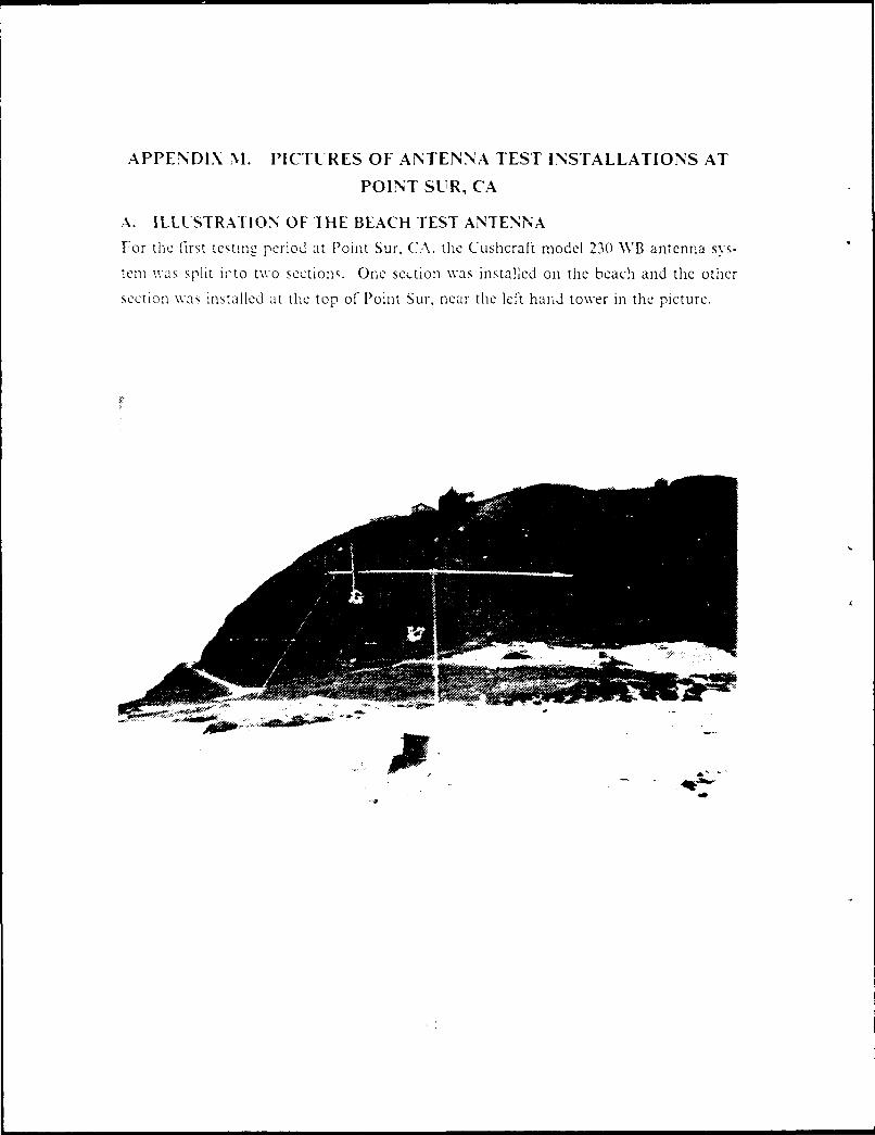
APPENDIX M. PICTURES OF ANTENNA TEST INSTALLATIONS AT
POINT SUR, CA
A. ILLUSTRATION OF THE BEACH TEST ANTENNAFor the first testing period at Point Sur, CA. the Cushecraft model 23() WB antenna sys-
tern wvas split iifto two sections. One sc.tion was installed on the beach and the other
section wa, Installed at the top of- Point Sur. near the left hand tower In the picture.
-JE

B. ILLUSTRATION OF THE TEST ANTENNA ON THE TOP OF POINT SUR.
For both tc',t periods at Point Stir, only half'of the Cushcraft 230 NVB antenna %vas uscd
as ilustIrated beclowv.

AxPPEND)IX N. CUSI1CR-FT 230 WVB ANTENNA INSTALLATION AT
THE NPS MARS STATION
l1ie antn ir. ,I, more I,- 17 1,,a~ on the radio tower at the N PS MIA RS station InIthe i N esahO I 'In lra ihe antenna is onl a heading of" 31 dcgre es, pointinto
Dar> , axnrort. CA\. In preper atio lolr1 thle anltenna tilt test. Th'lis is thle antennal Conl-
l aon [to he inst illcd at I oTIn Stir.1' CA, Onl thle tower illUstrated I ijLIrC IS.
-A*
Ow
*VO

APPENDIX 0. POINTS OF CONTACT
Chis Neuman AANDERAO Instuments 508-933-812030F Commerce Way
Wnburn, MA 07801
Dale Pilsbury Oregan State University 503-754-2207
Dept of OceanographyCorvallis, OR 97331
Ed Webb Texas A&M 409-845-3366College of Geophysics
College Station, TX 77843-3146
Dave Brooks-Prof Texas A&M 409-845-5527
College Station. TX 77843-3146
John Stidd Cortland Cable 607-753-8276Jack Dower-Pres PO Box 330
Cortland, NY 13045
Jim Hanlon ENDECO 508-748-0366
Kevin McClurg Marion, MA
Thomas McCord NPS Lab Manager 646-2369Code 69RD A/V-878-2369
Monterey, CA 93943
LCDR Ric Bari.s Officer in Charge A/V-951-7595
Submarine Rescue Unit
San Diego, CA
P01 Rouse USCG Commander USCG Group MTRY 647-7300 100Lighthouse Ave.
Monterey, CA 93940
Dan Frye WHOI 508-548-1400Woods Hole, MA 02543 x2658
Bruce Mertz USN Freq Corrdinator A/V-836-!602
Fritz Point Sur Facility 625-5606
Mel Briscoe-Prof ONP 202-696-4441
Code 11, 2FLU80f, N rinex St.Arlinqton. VA 22219

Tex Ritter Big Sur Park HO 408-667-2316
Jim Pete Pfeiffer Big Sur State Park
Big Sur, CA 9392C
Jim Valdez-EE WHOI 508-548-1400
Woods Hole, MA 02543
Lon Hocker ONSET Computer Corp 617-563-2267
PO Box 1030
N. Falmouth. MA 02556
John Dahlen DRAPER Lab 617-258-1316
Jim Layne REPCO. Incorporated 407-843-8484
2421 N. Orange Blossom Trail
Dr a do. FL 32804-4806
HYDROPRODUCTS 619-792-1031
John Anderson Polar Research Labs 805-684-0441
Larpinteria, CA
Kim McCoy Ocean Sensors 619-943-7119
Encini.tas, CA

LIST OF REFERENCES
Beardsley. R.C, C.F. Dorman, C.A.riche. L K Rosenifeld anid C.D. Winlant. 19S7:,
Afat ine Beowniaiv I o-,,cr Z~r~COIDE. J. of Geo RES. Vol.9 2, p. 146 7 _ 1488.
L3ON le. J., 1 QS9, personal comm111unica tion1.
Mrso .G (.. and ). F. I r-c. 198,7: 1Iuuivcm',tls and' .lfohuds fit 0(c I) 1111
7 r(ucr: ,rncicnL%. Society- JoUrnalj. Vol1. 2: No. 2 p42-3T.
B~sac\ 1.F. Decnton. 1). Lrxe. M. Hufnt, F. NI ontgomnert. and R. Paxnec. N S:
NS"; cr - ifay ~t 1rn~H i cl~lc I),isa AcIUIIUUFm an b.. 7111 Pa~t5(p1 A L7cU - 101 C'm-l1 01(1
I\a.HF;:' Wo I Hole Oceanog. Int. Tech. Rept.. NVIIOI-SS-13.
Drok. )A. I 9 : fr;wj u'I re irnv l />uOccall .Xbwruzl's, J . Atmlosp-her-Ic
and Cj~I Oceni ChI., \Vo1 1. p 176- IS89.
Link 17: J' I~ I,,~b' icc)rin- I1ludbook, Mcciraw-I I il Book Co., N.Y.
I rxe. I). I. 1 9 ,7: D~ata I"k;cu .. simi/atwon andi Occan JbAicriln" Vo u~ I 11ole
()ccan:. Inq. 'I CCj Rept. \-I 101l-87-21.
I Ia'l . 11.. 1EdItor-in1-(lifI : Comuicbatiiuns SNyms Eni'iwIcinc' land!'' k.

11 brzcpa, Stan Your GatewaY to Packet Radio, American Radio Relay League,
\ew'inegton (:-I, I9SS
lamik. II., ed.. 161:, .lutenna Lngineering Hanlhook, NMcGraw-Hili Book Co., NY
Kiver, M.S.,19&o: F-A! Simplified. D. VAN Nostrand Co. Inc., Princeton. N.
Miller. R., 1MR6. li1 Plredicting Tropo Openings Using Meteorological Parameters
QFX. American Radio Rely Wiee Newieton, C"F, p. 12
P..1 ,'i>.. VA' .W. V. l3ruene, EAT.0 Schoonike, ho u S4: M0/ icAY Princple and Cir uit
.\lcGra -Hill Book :o- NY
i3Kkard . CIA.. and MV .1. Lrc.1y 2 ecitv P scl()cne b'W 1nI ~utl Perai-non
'r. :c. . lawl fouc.: lairview% Park. NYV
Robinson. M-R. 1.\. C'arton. N. Pinardi and C.0. Moores, 19S'6. 1) mna!a iorecajjq7in' d I)-
i~~~w~~: n neplt~::1:L.ei.z in thle Cal ';wnia Cutrrent. I. Pysical Oceanograp1\. Vol. 16
No 9 r. 159-15-9
R. th,-r. 1.1 1 JR., 13A:V Nlagncll, C.Greengrove and (:.:\. Winant, I 9'K' Real- Time Data
I 'c'Sea I1CCehfloloe\. Pl P- 1 6.
Schw/. 970: In! rmation, Iran.snzission, .lodulation and Noise, ".cGraw-Ifll book Co.,
Styiin 'IT*..--, 1 Iersnai communication.

1. Defense Technical Information Center 2Cameron StationAlexandria, VA 22304-6145
2. Library, Code 0142 2Naval Postgraduate SchoolMonterey, CA 93943-5000
3. Chairman (Code 68r) 1Department of OceanographyNaval Postgraduate SchoolNonterey, CA 93943-5000
4. Chairman (Code 63Rd) 1Department of MeteorologyNaval Postgraduate SchoolMonterey, CA 93943
5. Professor Steven Ramp 4Department of OceanographyNaval Postgraduate SchoolMonterey, CA 93943
6. CDR Douglas L. McKinney 29 Glenn AvenueSalinas, CA 93907
7. Director Naval Oceanography Division 1Naval Observatory34th and Massachusetts Avenue NWWashington, DC 20390
8. Commander 1Naval Oceanography CommandNSTL StationBay St. Louis, MS 39522
9. Commanding Officer 1Naval Oceanographic OfficeNSTL StationBay St. Louis, MS 39522
10. Commanding Officer 1Fleet Numerical Oceanography CenterMonterey, CA 93943
11. Commanding Ofticer 1Naval Ocean Research and DevelopmentP.O. Box 3000Bay St. Louis, MS 39522
91

12. Ccmmanding Officer 1Naval Environmental PredictionResearch FacilityMonterey, CA 93940
13. Chairman, Oceanography DepartmentU.S. Naval AcademyAnnapolis, MD 21402
14. Chief of Naval Research800 N. Quincy StreetArlington, VA 22217
15. Office of Naval Research (Code 420)Naval Ocean Research and DevelopmentActivity800 N. Quincy StreetArlington, VA 22217
16. Scientific Liaison OfficeOffice of Naval ResearchScripps Institution of OceanographyLa Jolla, CA 92037
17. LibraryScripps Institution of OceanographyP.O. Box 2367La Jolla, CA 92037
18. LibraryDepartment of OceanographyUniversity of WashingtonSeattle, WA 98105
19. LibraryCICESEP.O. Box 4803San Ysidro, CA 920-3
20. LibrarySchool of OceanographyOregan State UniversityCorvallis, OR 97331
21. CommanderOceanographic Systems PacificBox 1390Pearl Harbor, HI 96860
92

22. Office of Naval Research 1Code I122PO800 N Annex St.Arlington, VA 22217Attn: Dr. Mel Briscoe
23. Dr. David BrooksTexas A&MCollege of GeophysicsCollege Station, TX 77843-3146
24. Dr. Dan FryeWoods Hole Oceanographic InstitutionWoods Hole, MA 02543
93
Recommended