r
4k
I
SPACE SCIENCES LABORATORY
N65-34461I (ACCESSION NUMBER)
(THRU)
.1 (PAGES) (CODE)
: C I_ & -?/_oi9 0(NASA CR OR TMX OR AD NUMBER) (CAT£GO
UNIVERSITY _ CALIFORNIA
" BERKEL__IFORNIA ,
,, _'_ GPO PRICE $
CFSTI PRICE(S) $
Hard copy (HC)
Microfiche (MF)
f-<
ff 653 July 65
https://ntrs.nasa.gov/search.jsp?R=19650024860 2018-09-07T10:47:36+00:00Z
Space Sciences Laboratory
University of California
Berkeley, California
A THEORETICAL AND EXPERIMENTAL STUDY
OF THE MECHANICAL _HAVIOR OF THE CORNEA WITH
APPLICATIC_ TO THE MEASUREMENT OF
_TRAOCUIAR PRESSURE
Nathan Jay Schwartz
Series No. 6, Issue No. 31
Sis work was supported by NASA Grant NsG 600
28, 1965
SUHHARY
A theoretical and experlmental study was made of the n_chanicai behavior
of the cornea. The theoretical analysis Included an analytical solution for the
symmetrical constraint of a thin, shallow, spherical shell by a rigid indenter.
The experlmental study Investigated the rheo|ogy of the cornea wlth particular
emphasis on Its compliance with the requirements of the Boltzmann superposltion
principle. Representative results of tests on twenty enucleated hog eyes and two
human eyes have been reported.
The corneas of the human and hog eyes behaved as |inear viscoelastic so|lds;
the human eyes differed from the hog eyes In having a long tern creep component,
Several eyes were tested at the slte of procurement, slx to seven minutes after
the animalms death, and It was established that creep is not an artlfact due to
aging or enucleation.
The analytical and experimental results were combined to study some Instruments
used to detect the level of pressure in the eye. The theoretical analysis predicted
that a tYPe of elastic Instabl]ity occurs during the process of flattening a small
portion of the cornea; this Is discussed with reference to the Goldmann and Hackay-
Harg tonometers. The role of cornea] creep was considered with reference to the
response of the Schi_tz Indentation tonometer during the time dependent process known
as tonography. _wO-c_
I
The nature of this study of the measurement of Intraocular pressure leads
to a three-fold presentation. We first give an analytlcal solution for the
symmetrical constraint of a thin elastic shell by a rigid Indenter, In the
next chapter we record our experimental investigation of the theology of the
cornea. And then, in chapter three, the analytical and experimental results
are combined to study some problems of tonometry and tonography.
Consequently, chapter one begins with an Introduction to the analytical
work, and the Introduction to the second chapter addresses itself to the experi-
mental study. In the introduction to chapter three, we orient the previous
results toward the glaucoma problem; therein we discuss the limitations of
applying our results which are based on the linear theory of elasticity to the
analysis of various Instruments employed to measure intraocular pressure.
Although the basic analytical fomulation is contained in chapter one,
the problem of tonography requlres an extension of these results. And In order
to gain a slight Insight into that problem, In Ghapter 3 we extend tim
previous results to Include the rising lntraocular pressure (due to the applied
load][, the fluld outflow and some heuristic remarks based on the linear theory
of visco-elast iclty.
Ii
TABLE OF _ONTENT$
Preface
1. An Analytical Investlgatlon of the deformation ofa Shallow Spherical Shell By a RIgld Indenter
I.I Introduction ..... ......................................,.......... 1
1.2 Reference Equations and Some Preliminary Results .................. 4
1.3 The Fomulation of the Boundary Value Problem ..................... 13
1.4 Tke Homogeneous Solution of the Equations Governingthe Boundary Value Problem ..,.,..,..,,..,..,.,.,.,,,,,...,,,,..,,, 15
1.5 The Solution for a Point Load at the Apex ......................... 19
1.6 The Symmetrical Constraint of a Shallow Spherical ShellWith No Edge Restralnt ....°.... ..... ..,,......,.,..,...,...,,,.... 25
1.7 Discussion of the Results for a Flat Indenter ..................... 30
Appendix I A The Evaluation of _p ..................................... 31I B The Evaluation of the Resultant Stresses
and Couples ........°....,,,.°°°..........°..,,..,°.,...,. 32I C The Evaluation of the Integrals of 1.6 ,.,,°..,.°...,°..,. 34
° An Experimental Study of the Rheology of thecornea In- Vitro
2.1 Introduction ............... ..... • .... .,,,.......................°. 36
2,2 Results From the Linear Theory of Vlscoelastlcity ......,.,.......° 38
2.3 The Description of the Experlmental Equipment .,.,,...,,.....,..... 40
2.4 Experimental Procedure ,...,,...,,,....,..,,-,.,,,-.,, .... ..,,.,.°. 43
2.5 Discussion of the Creep Tests .,,.....,..,.,.,,........,....,..,,.. 45
° Tonometry and Tonograpby
3.1 Introduction ....,,......,......,..,...,...,.............,..,,...,. 47
3.2 The Anatomy of the Eye, The GlaurJxu Problem ...,,,...,......,.,,. 48
3.3 A Structural Hodel of the Eye ................................... 49
3,4 Applanation Tonometry ,,.,o..,,,,,,,,,,,,.,,,,,,,,,,,,,,. .... ,,.. 5it
3,_A The Goidmann Tonometer .,.°,,,.,. .... ,.,,,,.,,.,,,.,, .... .. .... ., 56
3.4B The IMckay-Harg Tonometer .,..°,,,..,,.,..,..,..,..,,,.,,..,,... 59
3.5 Indentation Tonometers .,..,.,. ....... ,,. ...... .,...,.,..,..,,,. 65
Acknowledgement o.,.,..,.,,,,.°,o,.,.,,. ..... ..,.°.,,.,,.,o°....°.....,..- 73
References ...... .... ............................... .... ............-....- 7_
Figures ...°. ...... ° .... °.....°..,,°...,°..°..,,,..°,,...°...°...°.°,..°.. 77-108
CHAPTER O_IE
"An Analytical Investigation of the Deformation of a ShallowSpherical Shell by a Rigid Indenter"
1. ]. /ntroduct ion
The contact problem in elasticity is a boundary value problem of mixed
type. Over a reglon, whose boundary is not a-priori known, displacements
are specified; outside this region one specifles stresses. The solution must
determine the stresses and displacements throughout the body as we] ! as the
boundary between the loaded and unloaded portions of the surface.
A classical example of this type problem is Hertz I Ill _ solution for
the contact of two solid, elastlc spheres. In this investigation we are con-
cerned with the syn_etrical indentation of a shallow, spherical shell by a
rigid constraint. The shell is assumed to have no edge restraint,
In l_2, Essenberg [2] considered the problem of a plate whose upper
surface is partially constrained by a rigid, parabaloidai indenter. He found
It necessary to employ the E. Relssner [3J plate theory (which extends the
classical theory by considering the effect of transverse shear deformation)
since the classical plate theory predicts the following unsatisfactory result:
If a plate is loaded only from above by a rigid indenter whose contour is a
bl-harmonlc function, then the pressure between the plate and the constraint
is zero; equilibrium is maintained by a discontinuous resultant shear stress.
Essenberg was able to obtain a physical|y consistent representation
for the pressure; he also noted the dlvergence of the improved and classlcal
* Numbers in brackets refer to references given at the end.
2
theories even for very thin plates. He showed that if the surface traction
is a quantity of Interest, It Is necessary to employ the Improved theory.
In 19/46, E. Relssner [/4_ developed a theory to describe, from the stand-
point of classical shell-theory, the stresses and small displacements in
shail_ spherical shells. In 1955 Raghdi {7_ extended these results to include
the effect of transverse shear deformation and normal stress in the stress-
strain equations In the shell space.
For the problem that _e are considering, the shallow spherlcal shell
constrained by a rigid indenter, the result afforded by classical shell theory
(under the Love-Kirchoff hypothesis [8_ ) and the shallow shell approximation
is unsatisfactory. For constraint by any smoothly shaped indenter, classical
theory predicts that the pressure between the shell and the constraining sur-
face is negative, i.e., the shell does not contact the constraint. Equilibrium
is maintained by the discontinuous resultant shear stress at the edge of the
loaded region.
In view of Essenbergms success with the plate problem, we have solved
the problem of a thin shallow shell, with no edge restraint and symmtrically
loaded by a rigid Indenter within the context of the Improved theory due to
Naghdi _7] • If the loaded region does not become too large, the pressure dis-
tribution between the shell and the constraint is always positive; the shell
contacts the constraining surface. Beyond a certain contact radius, the
solution predicts a negative pressure at the edge of the contact region.
* Throughout the text we shall refer to those developments that neglect the
effect of transverse shear deformation and normal stress in the stress-strain
equations as the "class|cal theories", The extensions, to include these
effects_ shall be referred to as the "Improved theories'.
" 3
There Is some question of the consistency of an assumption inherent In
shallow shell theory (the existence of a stress function from which the direct
stress resultants are derived ) and the simultaneous consideration of the
effect of transverse shear deformation. This is discussed in the text for the
part i cu I a r contact p rob I om under cons i derat ion.
Numerical results are presented for several values of the radius of
curvature and shell thickness. And a physical Interpretation is suggested for the
prediction of an eventual loss of total contact between the Indenter and the shell.
• 4
1.2. Reference Equations apd Sa_ Preliminary Results
A derivation (from the general bending theory of shells) of the equations
of shallot/ shell theory is available in the text by Green and Zerna _91 . The
extension to include the effect of transverse shear deformation was carried
out by Naghdi [71 . Here we wish to recall the assumptions necessary to reduce
the differential equations which govern the resultant stresses and couples in
the shell space to the approximate equations known as shallow shell theory.
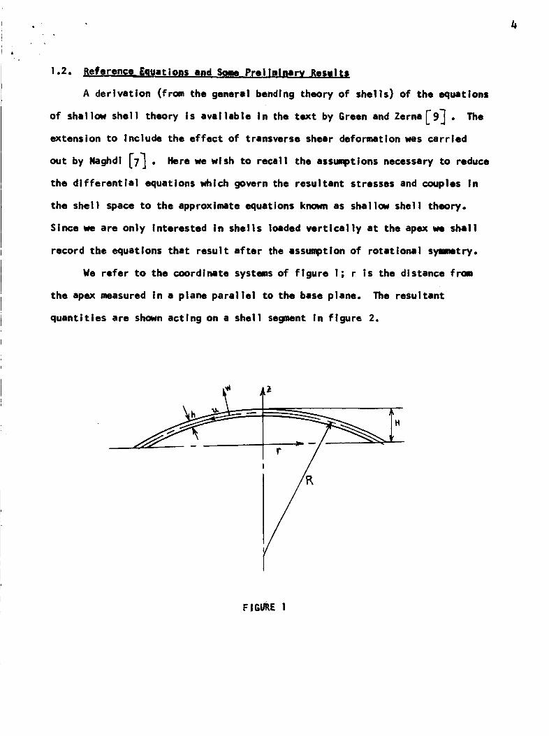
Since we are only interested in shells loaded vertically at the apex we shall
record the equations that result after the assulq)tlon of rotational symmetry.
We refer to the coordinate systems of figure l; r is the distance from
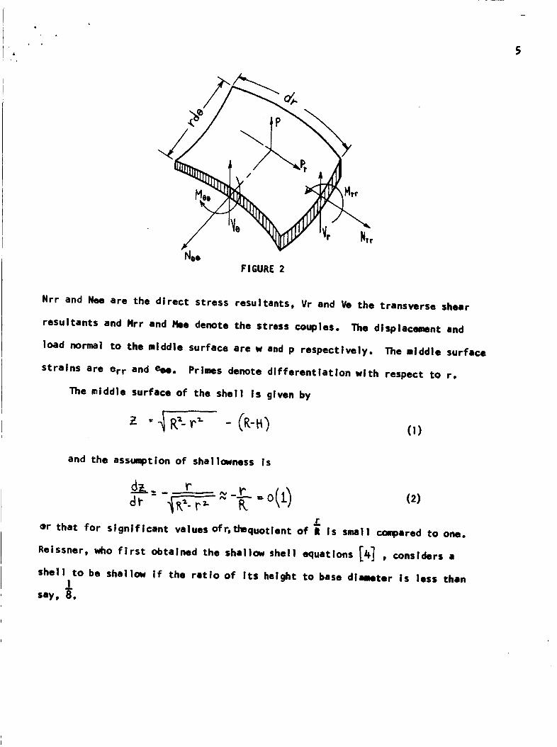
the apex measured in a plane parallel to the base plane. The resultant
quantities are shown acting on a shell segment in figure 2.
F.I GI/P,E 1
5
_tvr
NooFIGURE 2
Nrr and Nee are the direct stress resultants, Vr and Ve the transverse shear
resultants and Hrr end I_e denote the stress couples. The displacement and
load normal to the middle surface are w and p respectively. The middle surface
strains are err and ego. Primes denote differentiation with respect to r.
The middle surface of the shell is given by
and the assumption of shallowness Is
3_or that for significant values ofr, thequotlent of It is small compared to one.
Reissner, who first obtained the shailo_ shell equations [Jt] , considers 8
shell to be shallow if the ratio of its height to base diameter is less then
say, _.
4
6
In their rotationally symmetric form, from [6] , the equilibrium equations
are
(3a)
(3b)
in order to Introduce a stress function, the term_P r is omitted inUsually,
(3a). But in this section we wish to draw some conclusions that do not depend
on the existence of a stress function.
If we denote Poissonms ratio by _ t Young ms modulus by E, and tl_ shell
thickrmss by h, then the middle surface strains may be written alternatively
in terms of displacements and stress resultants as
+ : I_ _
hE
eee = "F"I"-- l_E:
and the stress strain equations are completed by
(4a)
(4b)
M. - _D l_/,. + 0_,')
/'3, -'_"+ -5'E_ "_"
(Sa)
(Sb)
(5c)
where D = Eh3/12 (l- 7 2) • We now obtain a relationship between the shear re-
sultant Vr and the normal displacement w. We shall then see the singular per_
turbation nature (in the limit as h _ o) of the contact problem.
7
where
If we substitute (Sa,b) into (3c), and replace B by (5c), then
- _r_,_ clr_ r d r
(6)
Now let
Then (b) becomes
whereV -J- =.
And from (6), in the limit as h _ o, we have
(7)
(8)
contact problem for shells.
2
Vr
Hence, if we obtain the non-dimensional shear resultant of classical theory [4] ,
as the limit _s the thickness approaches zero in the improved theory, we make
a singular pertubation. (Alternatively, we can obtain the dimensional shear
resultant of classical theory In the limit as k2-,00 in equation (6)). This is
the root of the divergence of the classical prediction for the pressure from its
improved value [2] even in the limit of a very thin plate. And from this singu-
let pertubation relating the two theories we account for the improvement in the
pressure distribution that is obtained by employlng the Improved theory in the
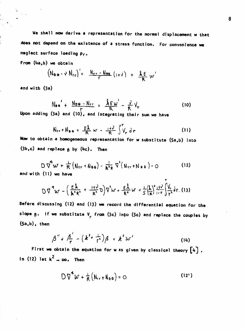
We shall now derive a representation for the normal displacement w that
does not depend on the existence of a stress function. For convenience we
neglect surface loading Pr.
From (4a,b) we obtain
r -_-
and with (3a)
I
N°.' + N_.- N_ _ __ - ± V,t- K K
Upon adding (3a) and (10), and Integrating their sum we have
(io)
Now to obtain a homogeneous representation for w substitute (Sa,b) into
(3b,c) and replace B by (/+C)o Then
8
' : (12)
and with (11) we have
Before discussing (12) and (13) _e record the differential equation for the
slope B. If we substitute Vr from (3c) in¢o (5c) and replace the couples by
(5a,b), then
/ • 2
r' -- (14)
First we obtain the equation for w as given by classical theory [4] .
In (12) let k2 ._ oo. Then
(12')
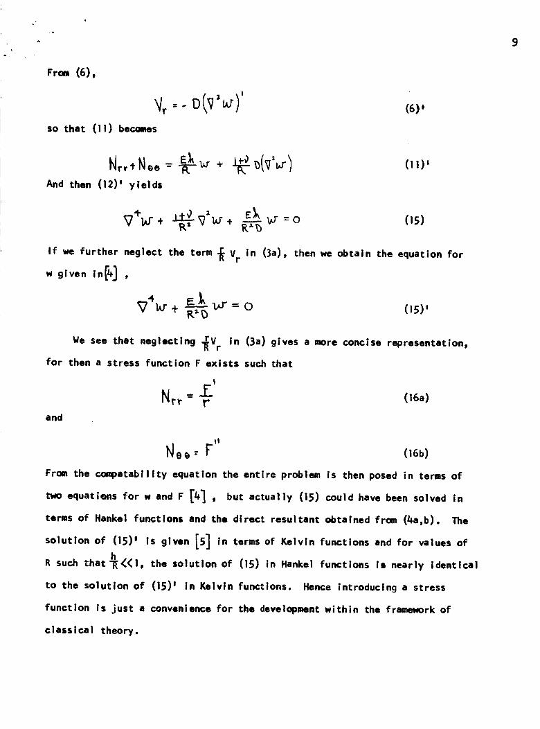
From (6),
so that (11) becomes
(6),
N,,+No.-And then (12)' yields
(!1) m
_,, to" + _--_(15)
If we further neglect the term _ Vr in (3a), then we obtain the equation for
w given in[/+] ,
_4h. r + I=_.._ V = 0 (15)'R_£:)
We see that neglectlng _V r in (3a) gives a more concise representation,
for then a stress function F exists such that
Nr_"= r (16a)and
tQ__ --F (16b)
From the coq)atability equation the entire problem is then posed in terms of
two equations for w and F [4] , but actually (15) could have been solved in
terms of Hankel functlons and the direct resultant obtained from (Lla,b). The
solution of (15) m is given [5] in terms of Kelvin functions and for values of
R such that-_(I, the solution of (15) in Hankel functions Is nearly identical
to the solution of (15) I in Kelvin functions. Hence introducing a stress
function is just a convenience for the development within the framework of
classical theory.
I0
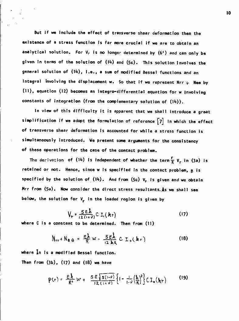
But If we Include the effect of transverse shear deformation then the
existence of a stress function is far more crucial If we are to obtain an
analytical solutlon. For Vr is no longer determined by (6 m) and can only be
given in terms of the solution of (14) and (5c). This solution |nvolves the
general solution of (14), I.e., a sum of modified Bessel functions and an
Integral involving the displacement w. So that if we represent Nrr + Nee by
(11), equation (12) becomes an integro-dlfferentlai equation for w involving
constants of integration (from the complementary solution of (14)).
In view of this difficulty it is apparent that we shall introduce a great
simpliflcation if we adopt the formulation of reference [7] in which the effect
of transverse shear deformation is accounted for while a stress function is
simultaneously Introduced. We present some arguments for the consistency
of these operations for the case of the contact problem,
rThe derivation of (14) is Independent of whether the term_ V r in (3a) is
retained or not. Hence, since w Is specified In the contact problem, B is
specified by the solution of (14). And from (5c) Vr is given and we obtain
Hrr from (Sa). Now consider the direct stress resultants. As we shall see
below, the solution for Vr In the loaded region is given by
c (17)=where C is a constant to be determined. Then from (11)
,z kK
where In ls a mdlfled Bessel function.
Then from (3b), (17) and (18) we have
R--i- ,, CI.(kr) (19)
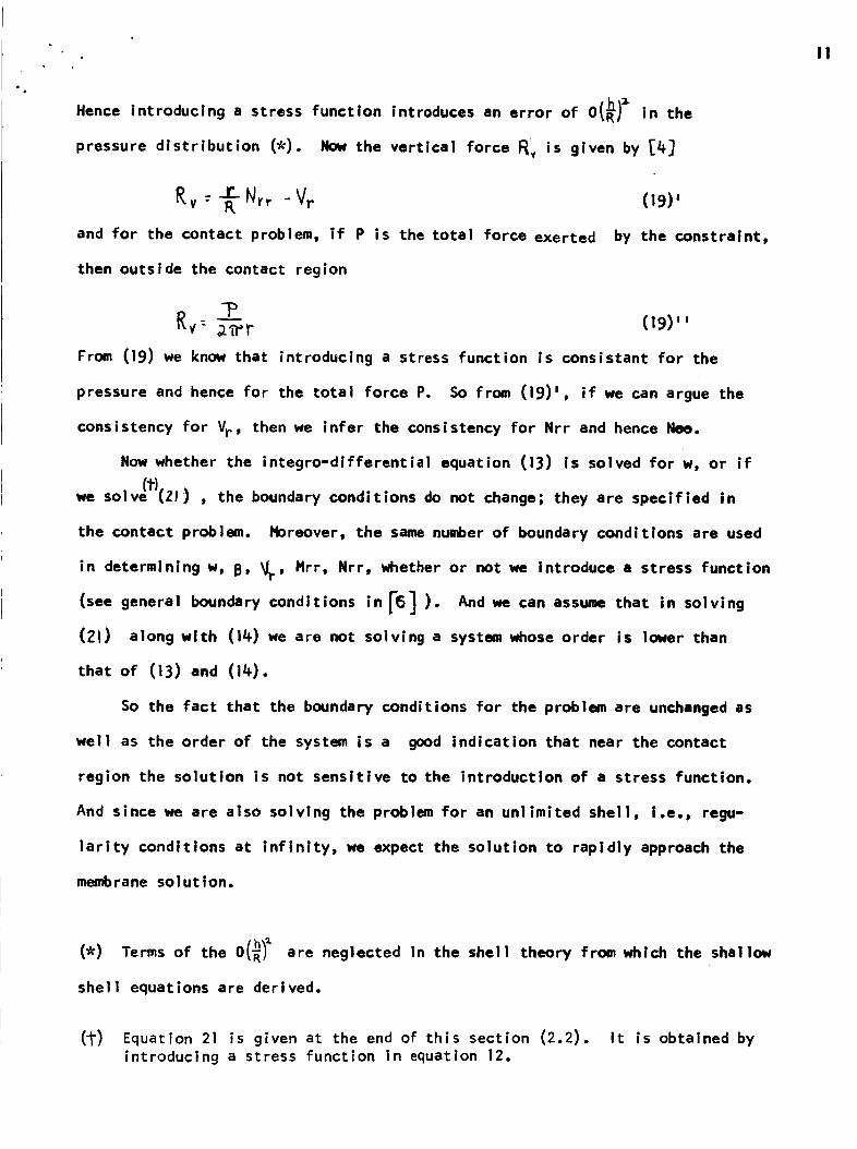
Hence introducing a stress function introduces an error of 0 in the
pressure distribution (_). Not, the vertical force F_:v is given by _4_
- Vr (19)'Rv: R
and for the contact problem, if P is the total force exerted by the constraint,
then outside the contact region
From (19) we know that introducing a stress function is consistant for the
pressure and hence for the total force P. So from (19)', if we can argue the
consistency for V¢, then we infer the consistency for Nrr and hence Nee.
Now whether the integro-differential equation (13) is solved for w, or if
we soiv(t)(ZI- ) , the boundary conditions do not change; they are specified in
the contact problem. Horeover, the same number of boundary conditions are used
in determining w, 13, _r' Hrr, Nrr, whether or not we introduce a stress function
(see general boundary conditions in ['6] ). And we can assume that in solving
(ZI) along with (14) we are not solving a system whose order is lower than
that of (13) and (14).
So the fact that the boundary conditions for the problem are unchanged as
well as the order of the system is a good indication that near the contact
region the solution is not sensitlve to the introduction of a stress function.
And since we are also solving the problem for an unlimited shell, i.e., regu-
larity conditions at infinity, we expect the solution to rapidly approach the
membrane solution.
II
(*) Terms of the 0(_1 _ are neglected in the shell theory from which the shallow
shell equations are derived.
(_) Equation 21 is given at the end of this section (2.2). It is obtained byintroducing a stress function in equation 12.
12
It is therefore reasonable to simultaneously Introduce a stress function
and the effect of transverse shear deformation for the contact problem, If
the load instead of displacement were specified, then (13) or (2.1) would be
solved with different boundary conditions and it would be difficult to argue
the suitability of introducing a stress function. One would probably have to
solve (13) by _symptotic integration.
In the contact problem, the continuity of Nrr yields the unknown contact
radius. The expression for Nrr in the unloaded region, in order to satisfy2
0(_), should be obtained from (19)'. Then, the continuity ofequilibrium to
Nrr as determined from the stress function F will yield a remaining constant
of integration in the problemt (the constant A9 in equation 41 below)
And so we close this section with the field equations as derived in _71 .
These equations will be employed in the solutions of the contact problem in
the unloaded region.
(20)
(21)
13
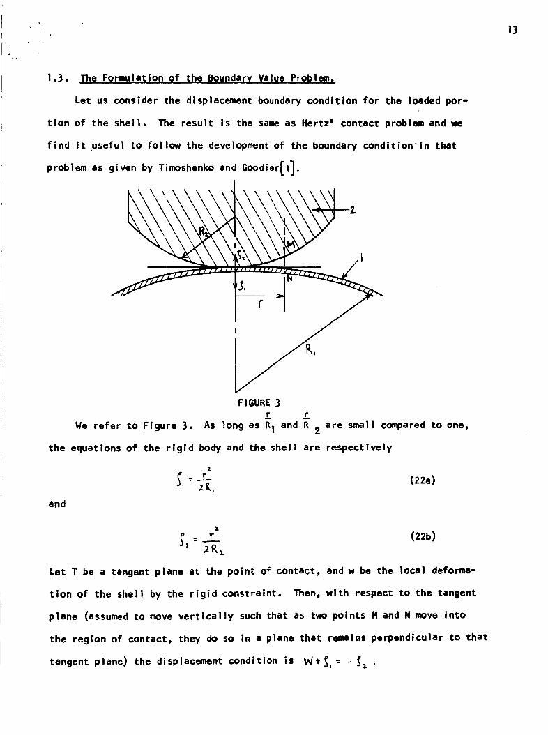
1,3. Ihe Formulation of the Boundary Value Problem_
Let us consider the displacement boundary condition for the loaded por-
tion of the shell, The result Is the same as Hertz _ contact problem and we
find It useful to follow the development of the boundary condition in that
as given by Timoshenko and Goodier[I].problem
We refer to Figure 3,
FI6URE 3r _r
As long as R1 and R are small compared to one,2
the equations of the rigid body and the shell are respectively
and
Z
(ZZa)
Let T be a tangentpiane at the point of contact, and w be the local deforma-
tion of the shell by the rigid constraint. Then, wlth respect to the tangent
plane (assumed to move vertically such that as two points H and N move into
the region of contact, they do so in a plane that remains perpendicular to that
tangent plane) the displacement condition is W_, = - _,
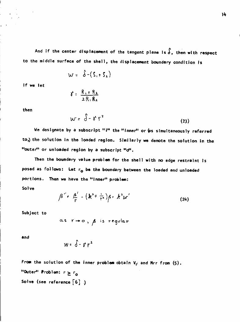
14
And if the center displacement of the tangent plane is _, then with respect
to the middle surface of the shell, the displacement boundary condition Is
If we let
then
o? _r 2: - (2.3)
We designate by a subscript "i" the "Inner _l or _#s simultaneously referred
to,) the solution in the loaded region. Similarly we denote the solution in the
"outer _l or unloaded region by a subscript mind=.
Then the boundary value problem for the shell with no edge restraint is
posed as follows: Let r o be the boundary between the loaded and unloaded
Then we have the "lnneP' problem:port ions.
Sol ve
r
SubJect to
o_S V"--_o
and
w= oe-rr
From the solution of the inner problem obtain Vr and Nrr from (5).
"Outer" Problem: r _ r 0
Solve (see reference ['6] )
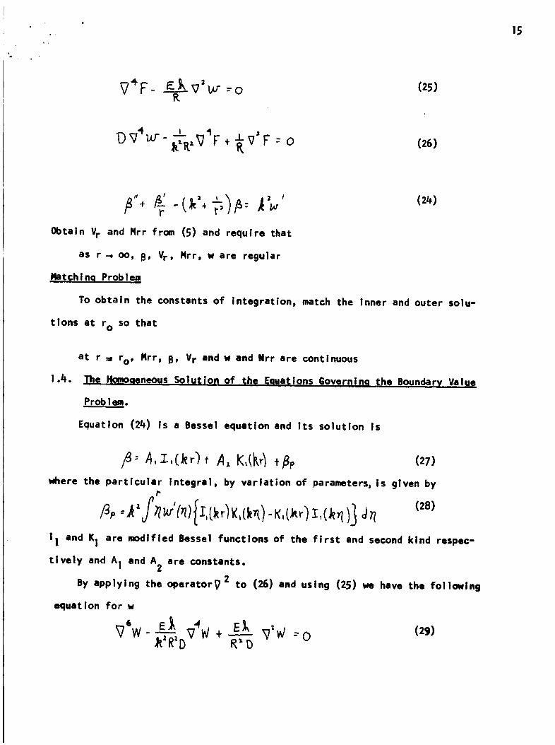
15
R(25)
(26)
r' (2_)
Obtain Vr and Mrr from (5) and require that
as r-, oo, B, Vr, Mrr, w are regular
Matchlnq Problem
To obtain the constants of integration, match the Inner and outer solu-
tlons at r o so that
at r = to, Nrrp B, Vr and w end Nrr are continuous
I._. The Homo neous Sol 1o of E ua ions ova ni the Bounder Value
Problem.
Equation (2_) Is a Bessel equation and Its solution Is
/_ 4,z,C_;)_ A, K,{k_l,_p (27)
where the particular integral, by variation of parameters, is given byP
I I and Kl are modified Bessel functions of the first and second kind respec-
tively and A I and A2 are constants.
By applying the operator_ 2 to (26) end using (25) we have the following
equal ion for w
_76W _J, "_ E_, (29)-_--_-,Dv _V+ "--'-R"D _'_ --o
16
By Iinearlty we factor (29) Into a product of three operators as
v_ (_'+c,')(_'+ c,') _ : oZ Z
where CI and C2 are the roots of
(30)
4 c_ c_ Ek :oC _ _=C'----b* R"-'--D
(31)
The solutlon of (29) Is
3
W = _,W_
where w_ are the solutions of
(v'_c,_)w,:o(v'_ cj)w_ =o
_zN 3 =0
if02 , Chapter 5] the factored operators commute and C,z_C z ,0 •
The solution of (3i) is
(32)
(33a)
(33b)
(33c)
L92. t
C, --_C(34a)
,. , -i.e
Cz : _"_f-
where the bar (---)" denotes the complex conjugate and
(34b)
__ _' i _-_°:z)f_-_ 'Since the requirement of oommutivity of operators and distinctness of the
roots Ci is met, the solution of (29) Is the sum of the solutions of (33).
We require a solution that is regular as r -, oo and therefore we take
the solutions of (33) In terms of Hankel functions,
Hfz_/ • (1)l-W = D, Ho("(c,r)+ D, o It,r)÷ D_Ho Ic,r_ (36)
17
where H(]n '2)
respectively. But (36) must be real and therefore we set
D,,D,_: D,' , D.3*D,; D3'
Then if we employ the Identities
ICI (,2_(0 x
are Hankel function of order n and of the first and second kind,
and solve (37) for OI and substitute Into (36)
(B7)
(38)
we have!
(39)(2)/
.r_ , "'" ")- D,'._ No(c,r)+ D,,,_,t -O_ -_Ho Lc,Where Re ( )¢ ) and Im( _ ) desiglmte the real and imaginary parts respectively,
Now if we further note that
hl o" (;): z 3.{,)- rl:"c,)uk^.^ , i_ a R_ssel function of order n then with (35) and for convenience
new real constants A i, the solution (39) becomes,
o)/w: A3_, _1:"(_')÷A_H0 _) _/1, P_3o(_)
f L_/z_-: E .where
From (25) the solution for F Is then given by
(40)
(41)
18
We note that if we neglect transverse shear deformation (k 2 . oo), then e-, 3_/2
and _-_r i 3/2. And if we recall that
(/_2a)
(42b)
I r r (42c)
where kei, ker, ber, and bei are Kelvin functions, then as k2-. oo, (40, 41)
reduce to Reissner's solution IS] •
1.5. The Solution for a Poin_ Load a.t the Apex t
To derive the solutlon to the problem of a point load at the apex of a shallo_
spherical shell having no edge restraint we shall employ the technique used by
Koiter (Ref. [161 ) in his solution for a complete spherical shell under point
loads at its poles. Accordingly, we require the following representation of the
divergence theorem: If S is the surface area enclosed by a smooth countour C,..+
and n is the unit normal vector to the contour C in the tangent plane to the
surface, then for a twice continuously differentiabie function _ on S,
Let us consider the solution for the normal displacement w_ and required that
_.S _'---+o_ W, W'
o. s r --_ oo , ,8 , W --_. o
(_a)
(_b)
(_c)
where w is the solution of equation (22) in the absence of surface loads except
for a concentrated force -P at the apex,
Our result (40) is the solution of the homogeneous form of (21), and the
only component that is bounded at r_--o and approaches zero at Infinity is
r Le/_)W---A3 R.eH:"CTc (++s)
And so in order to complete the solution we must determine the constant A3. But
we first record some formulas for the behavior of the value of Bessel functions
for small values of their argument°
If z is a complex variable, then by definition
Ir:O
19
20
We denote the real
fe' as a = by _n and
and imaginary parts of Jm (i_) with 2 in polar representation
Vn so that
If the Bessel functions Ym(E) have their real parts denoted by Urnand their
imaginary parts by Vm, then
We require the representations for n--o,l_--I
erence (17) we have
; from the introduction to ref-
(_e)
where So, To, Sl, T I are regular nearf_--o and _ is Euler's constant.
We now proceed wlth the solution. Integrate equation (21) over a portion
of the surface of the shell, with p a concentrated load.
Then with
D _w 0/_+ " _,v") _"V'Fo/r = P
(4])
c 3
5
(47)
21
Now let c be a circular path symmetrical about the apex and given parametrically
by polar coordinates ro, CO. We take the limit of (L_7) as ro. o
ro-.O o D_'K o r-- ' e_'_
where-P is the point load and we have dropped the terms that obviously will not
contribute (see the conditions /#+a) in the limit as ro , o.
But from equation (201,
where a I and a2 are constants and a2 = o by (LiJ6a). Hence from (/+/+b) we see
that as r o. o the second term in (48) gives no contribution and we are left
with
to-do r "-to
Now since!
from (LIG f,g) we see that
Z
Where _(r) represents terms containing singularities 0 (In r) and the remaining
regular terms in the series expansion for HI(I) (_1. And since
( >) ( 1_- _,_'"(_ _% - c H,('_ " _J'
we have
Then (451, (/+9), and (51) yield
or
(s])
__ Tf ,o,v_e (52)
22
Hence the solution w8 for the point load is
C ")/_f ieb)I
From (42a) we see that as k2 -_ oo, (i -, 3t_12) t
(53)
,l'"lr;.e/,).--,.z.6.u_.Z
and
_r
the solution given by Reissner[5].
We now determine the stress function F given by equation (Z_l). From the
determination of constants in the solution for w, we see that,
(5_)
and we must determine A9. But this follows immediately from requiring Nrr to be
finite at r = o. From equation (lO), Nrr =-F/r, so from (5/4) and (50)
we see that Nrr is given by
I J }T_
And then the requirement (/_/¢a) is met if
And with A_ given by (52) we have
(56)
Hence, the stress function F6 is
(57)
" _ f _l_r-_e''''c _°/'fi _t (58)
.- 23
if we make use of (42b), we see that as kLCO 3 e--_ 51r/a"
F6,__ _ __It
the result derived by Reissner[51 .
To complete the solution we require B"
B = A, K,(_," / , /g,
end _p is given in appendix I, equatlon (h) so that
_ T 3
From (27), with A t ,= o by (Idtc) we have
(59)
(60)
Now, from equilibrlum, the total resultant normal force Vv acting on a vanishingly
small circular region with center r = o is
2_
_/v: " .ITI"V" o-lib (6l)
r-_o
With Vr given by (5c), Nrr from (55) and recalling Ill, page !15] that
where _ (r) represents terms bounded near r = o, equation (61) becomes
' twhere _e
And with the behavior of H1(I) (il) given by
yields
(50), and A) from (52), (61')
_F _zC_P)Jc{ k'f_h_.o t(62)
• : 24
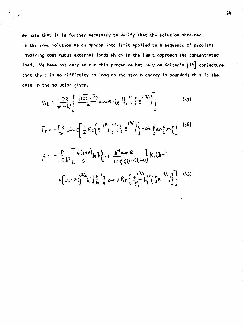
We note that it is further necessary to verify that the solution obtained
is the same solution as an appropriate limit applied to a sequence of problems
;nvolving continuous external loads which in the limit approach the concentrated
load. We have not carried out this procedure but rely on Koiterls _16] conjecture
that there is no difficulty as long as the strain energy is bounded; this is the
case in the solution given,
(53)
(6B)
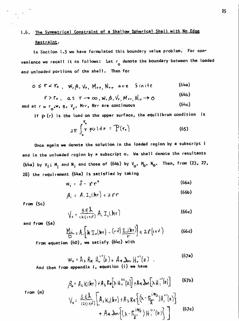
1.6. Ihe SymmetriFal Constraint of a Shallow Spherical Shell with No Edqe
Restraint.
In Section 1.3 we have formulated this boundary value problem. For con-
venience we recall it as follows: Let r denote the boundary between the loadedo
and unloaded portions of the shell. Then for
S fo _e
Ir> ro , o.s
and at r = r ,W, B, V0 r'
_ -- oo, w,/_, q,, M,, k/,, -_ oMrr, Nrr are continuous
(64a)
(64b)
(64c)
If p(r) is the load on the upper surface, the equilibrum condition
ro/I
(6S)ao
is
Once again we denote the solution in the loaded region by a subscript i
and in the unloaded region by a subscript o. We shall denote the resultants
(64a) by Vi; Mi and Ni and those of (64b) by V, Ho, No.
28) the requirement (64a) is satisfied by taking
Then, from (Z3, 27,
From (5c)
and from (Sa)
5_k
)From equation (40), we satisfy (64c) with
W_ : _'- _r z (66a)
(66b)
(66c)
(66d)
And then from appendix I, equation (i) we have
(67a)
from(m)
i
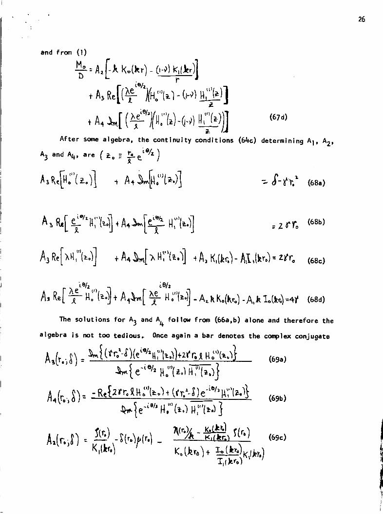
' 26
and from (l)
r. ;%
+A4_[ (-_')(W."v',z,-Q.o)H,"'r_))1
After some algebra, the continuity conditions
A3 and A4, are C _-o -
['" (1)/
i--
(64c)
(67d)
determining A1, A2,
= Z _o (68b)
(68c)
. '_% LeA
A, Ke[Ae ,."', _ ,,,,qT "° L'I+ A4_[ _ No 1,1.A, kKo(k,o).A,_]:o(_4-,_(68d)
The solutions for A3 and A4 follow from (66a,b) alone and therefore the
algebra is not too ted|ous. Once again a bar denotes the complex conjugate
, I_o/]+ztr,_, I_o t_._s (69a)A,(,..)XI: " '"'
e"_e/'I'Io , (_a
27
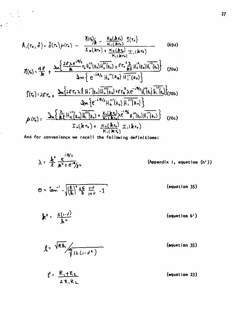
And for
¢ • (Appendix IX- T ,_"_e'%,. equation (h'))
8- _,,-'- jL-_y_l''>_,_-& '(equat ion 35)
(equation 6')
(oquat ion 35)
(equation 23)
28
Greens function for the problem, WS, .derived in section i.5.
Hertz' problem [I J , the center displacement 6 (r O) satisfies
We now recover the center displec_ent 8(r o) which follows from the
For as in
Cand p(r) is now given by (3b, ll)
And from (53)
(71)
(72)
Where
_I_ )] (73a)
(73b)3 -- - -- _.'II"" "_=
From (71,72,73) it is evident that we require the following Integrals:
(for details of the evaluation see appendix 1, section C)
A,(t.3-O
^_.zi*_/ __ ,,,,,'n "-'" } (74a)
(74b)
• 29
0_ ,., _ _b/.
O
9,•(7_c)
Then substituting (72) Into (71), making use of (73) and letting
_: _e._ _] (75)
results In
- _ s_ cor.) x_C_.)}(76a)
and C (to) = _(_t%_ - l<.(Jero )I_,(._ ,.) _'(.r'o ) (77)
To obtain a relationship forl_and r ° we employ (65) (or the continuity of
_rr, with Nrr consistant with (65)), and with pand _ as given by (72) and
(76a) respectively.
(78)
With A! (ro; _) and _ (ro) given by (69d) and (76) respectively.
30
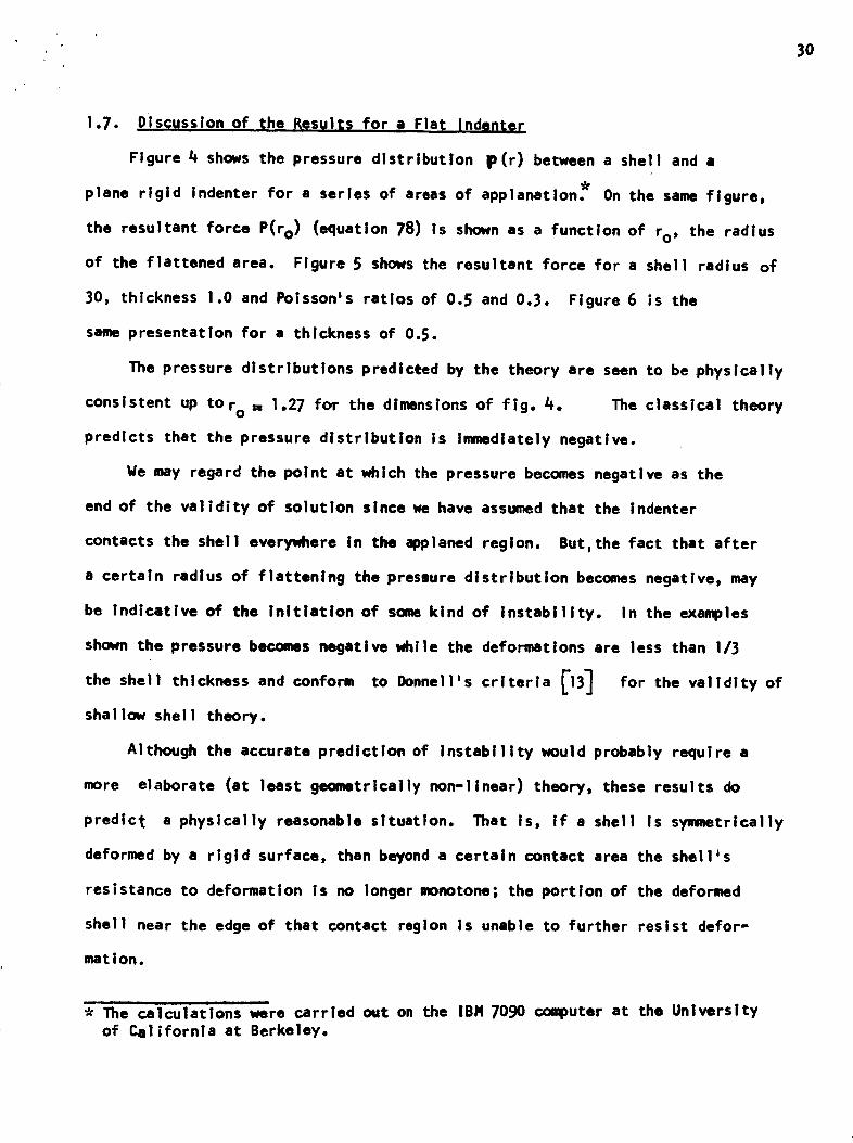
1.7. Discussion of the Results for a Fla t indente r
Figure 4 shows the pressure distributlon p(r) between a shell and a
plane rigid Indenter for a series of areas of applanation_ On the same figure,
the resultant force P(ro) (equation 78) ls shown as a function of ro, the radius
of the flattened area. Flgure 5 shows the resultant force for a shell radius oT
30, thickness 1.0 and Poisson's ratios of 0.5 and 0.3. Figure 6 is the
same presentation for a thickness of 0.5.
The pressure distributions predicted by the theory are seen to be physically
consistent up to ro = 1.27 for the dimensions of fig. 4. The classical theory
predicts that the pressure dlstributlon is immediately negative.
We may regard the point at which the pressure becomes negative as the
end of the validity of solution slncewe have assumed that the Indenter
contacts the shell everywhere In the applaned region. But,the fact that after
a certain radius of flattening the presIure distribution becomes negative, may
be Indicative of the Initiation of some kind of instability. In the examples
shown the pressure becomes negative while the deformations are less than 1/3
the shell thickness and conform to Donneil's criteria _13] for the validity of
shal low shel ! theory.
Although the accurate prediction of instability would probably require a
more elaborate (at least geometrically non-linear) theory, these results do
predict a physlcally reasonable situation. That is, if a shell is symmetrically
deformed by a rigid surface, than beyond a certain contact area the shellas
resistance to deformation ls no longer monotone; the portion of the deformed
shell near the edge of that contact region is unable to further resist defor-
mation.
i I
_11_e calculations were carried out on the IBH 7090 computer at the Universityof California at Berkeley.

. 31
. Appendix I
A. The Evaluation of _,n
We evaluate the particu]ar integral Bp, equation (28) with w given by
In (b) let
are two cylinder functions, then ['i5, pg. 90 1"=(a)
(b)
J,
and recall that
K,_w,tl:-_.',"(_k,Ll
K,_hl:-_-},;"C_h)
(d)
Then from (b,d) we have
r ¢iO/z. .
(e)
and
r
e /J.,O,,L/._=
e;'ejz_..._ .. ix" ke_
+T .L,t_)_,+,_e}j"(f)
32
From (e,f) it follows that
Ik
And hence, from (28), (a) and (g) we have
(g)
where
(h)
B. _valuation of The Resultan_ Stressgs and Couples
given by equation (b), for the normal dlsplacem_nt w from equation
slope B is (27,h)
We first evaluate Mrr, i_, Vr as given by equation 5, Nrr and Nee as
(o). The
(m)
33
From equation (a)
' A3R_I e_l" '"
and we denote this and similar expressions below as
-_ : A4 i-NC"( IA_ _,( o)
Differentiating (i) yields
_r - it'"
+ I As Re Ebl_ )}
Hence
(!)
(m)
°
34
and
.J
The direct resultants are obtained from equation (16) as
(n)
(o)
(p)
T_he Evaluation of the In.teqralsAl,A 2_./_3. of sectionC.
These integrals are evaluated with the aid of equation
the result [18, pg, 133]that for WII a cylinder function,
X "÷0
p_z.
lo
(b) of Appendix I,
and the following limits(which result from the formulas
r _o
[,,.,.
(r)
35
r-,)o
=o (s)
From
The lower
(q) we have
ro ' ;)1_)
0
limit is evaluated using (r) above;
- eg%/-s "'/-r i'_(T/ r_l, ,_e '/')
/ "_el,.Vz )]
setting i_e - -_- e i_& _ we have
The evaluation ofA 2 (ro) follows similarly from (q and r) as
and A 3 (ro) follows from (b)) (r) and (s)
fo
o
I C :_/,,,
- '-¢____,+J, t_ 14,{_:,I,,Oe_)v +
, {_ie,i-,IEa
,t*
Cv)
36
CHAPTER 2
Ap F-xperlmeql;a,,1 Study of the Kh$oloav of the _..rltea in .Vitro
2. |. _nt roduct Ion
The purpose of thls study Is to understand under what conditions of
magnitude and duration of loading the cornea behaves as a linear viscoelastic
sol id. Accordingly, our experiment has been designed to ascertain under what
circumstances the cornea conforms to the requlrements of the Boltzmann Super-
position principle. Basically we have relied on hogs eyes, but several human
eyes have also been tested.
An attempt was made to assess any changes in the me_hantoal properties
of the cornea due to physiological change after death. Hence, we performed
some experiments at the site of procurement of the enucleated eyes, approxi-
mately six minutes after the animal's death. Although the results show some
consistency, the temperature was not controlled and due to the simultaneous
action of the variables age and temperature the results oti the aging dependency
of the mechanical properties of the Ln vltr.._._ocornea must be regarded strictly
as prel Iminary. Ifmmver, It was definitely established that the creep response
shown by the cornea is not an artifactual result of emucleatlon.
The experiments may be grouped as follows:
A. Creep Tests at an t_traog_lar pressure of /_Omm.tt_. (FIQures 9-15).
These experiments represent the most complete element of the rheological
study. An Internal pressure of /+0mmJlg was choosen to simulate the state of
the cornea under Schidtz tonametry or tonography. The plunger diameter in these
tests was 3 ram. This dimeter and the loading range (/+ g. to 12 g.) are approp-
rlate to the conditions during the application of the Schi_tz tonometer.
B. Creep Test._ at a Fixed Load and_Different Intraocular Pressurew. (Fiaures
37
These experiments were designed to investigate the dependence of the
rheologicai behavior of the cornea on the level of intraocular pressure. The
creep response of the cornea was measured for a given load and an intraocular
pressure fixed at the consecutive values of 20, 30, 44), 50, and 6Omm.,g.
To obtain a description of the corneal response at a loading range per-
tinent to appianation tonometry, a larger plunger (/4mm. diameter) was employed
with a loading range of 2-12 grams. Hence we have an applied pressure (due to
plunger loading) that is at one degree considerably lower than class A and
its upper range overlaps the lower loading range of the experiments in class A
C. _orneal C_press{on Tests, (Fiqure 21).
Since the cornea is capable of compression, this deformation mode was
investigated as follows. A portion of the cornea was removed and placed on
a steel bali whose radius was approximately equal to the corneal radius at
an internal pressure of 20mm.Hg. The experiments were then performed as
though the cornea was supported by an intraocular hydrostatic pressure. Since
we are basically interested in the instantaneous (elastic) compression response,
the steel bail was thought to present a negligible source of error from the
viewpoint of obstructing the diffusion of fluid across the inner surface of
the cornea.
D. Yolume Expansion Tests (Fiqure 22_. (Eye Loaded Only by the Intraocular
Pressure).
When the intraocular pressure Is raised, the upper surface of the cornea
(and sclera) symmetrically deforms. If the materiel behaves linearly, and a
pressure increase from Po to Po + 6P yields an increased displacement 6w,
then Po + _pshouid induce a dlsplacement change of(_w. These tests were
38
designed to check the material I lnearity of the eye in this deformation mode.
A pressure range of 20 - 60ram.rig. was covered in lOmm.tig. Increments.
In section 2.2 we record some Ideas from the theory of linear visco-
elasticity. Section 2.3 contains a description of the experimental equipment,
and in section 2.4 we describe the experimental procedure.
The results of the creep tests are discussed in this chapter (section
2.5). The corneal caapression tests and volume expansion tests respectively
provide an estimate of the foundation constant (see chapter 3) of the corneal
stroma and the Young's modulus of the combined layer of Descemetls membrane
and the pavement epithelium (see Figure 23). These tests are pertinent to
the measurement of intraocular pressure and are discussed in chapter three.
2.2 Besults from the Linear Theory of Viscoelasticity
The results stated here are from the foundations of linear viscoelasticity.
have been rigorously given by Gurtin and Sternberg [ref. 26] . Dis-These
cussions oriented toward engineering application are numerous; here we refer
to the discussion by Lee [ref.26] • The distinction of a semi-relaxing
viscoelastic solid is due to Hunter [ref. 25 ] •
If Pand (l are linear operators in time, and O'(t) is the stress variation
with e. (t) its corresponding strain variation, then a material is linear
viscoelastic if it obeys the law:
The relationship (79) may also be given as a hereditary integral. The exis-
tence of this representation stems from the postulate of i inearity which is
equivalent to the Boltzmann Superposition principle:
Let a particular load variation be given by
39
and the deformation response by
Sct 2 lt)
Then if the load is changed to
(79b)
L t{)= _,, L, lt) (79c)where _r are a series of constants covering the domain of loading, then the
superposition principle requires that the resulting deformations
satisfy
k'(t) - 2, (79d)
If the requirement outlined in (79) is met, then the stress and strain
in the body are related by a Ouhamel integral as
where_'(t) is known as the creep function. Alternatively
t/1
where G{t) is known as the relaxtion function.
A material is called seml-relaLxing if the extension response due to
an applied constant load approaches a finite limit as time Increases, It is
possible to show that for such materlals_ the force required to maintain a
constant deformation does not fall to zero in time but appraoches a constant
va 1ue.
In order to check theapplicabllity of the superposition principle (79)
cXr
_O
as a function of time and see if these curves (for successive _r) coincide
with the curve 6,(t). A viscoelastic material will have a response curve
6 (t) that differs in shape from the load curve L (t). The special case of
an elastic solid is included in (79); in that case the load and deformation
response curves wi II have the same shape.
If a material can be represented by the laws (80) or (81), (i.e. 79
holds) and is of a semi-relaxing nature, then in the quasi-static case,
assuming the boundary conditions for the elastic and viscoelastic problems
are the same, the viscoelastic result follows by a correspondence principle
applied to the solution of the elastic problem. (see section 3.6).
2.3 The Description of the Experimental Equipment
To facilitate the discussion we first give a review of the equipment
employed. Each item is designated by a numeral and shall be referred to by
name (e.g., motion transducer) and numeral. The detailed description of any
particular apparatus will now be given and this list is referred to in the
text.
I. Hotion Transducer
The mechanical transducer employed was a Taft-Peirce Versacheck Electronic
Gage. The basic equipment consists of 1) a pick-up head which operates
on the linear differential transformer principle and is capable of
detecting motion changes of the order of ! x 10-6 inches. 2) A phase-
sensitive3extremely linear, carrier amplifier to magnify the trans-
ducer signal, and a I)C meter which reads in fractions of an inch.
The Versacheck unit has an internal calibriation circuit for determ-
ining the gain of the entire circuit. The unit may be selected to
operate any one of four meter graduations: In inches these are
41
5 × !0 "4, I x 10-4 , 5 x 10⁻⁵ , ! x l0 "5.
The meter is of the dead beat type, accuracy to within I_ and a
response time of ¼ second with no over shoot. After a 30 minute
warm up time, the stability is 2 x 10⁻⁶ inches per hour assuming
good temperature control.
II. Brush Recorder Hark II
This recorder was used to continuously record the motion transducerSs
output.
III. Pressure Transducer
The intraocular pressure was monitored by a Statham Hodel P23
pressure transducer.
IV. Visicorder Oscillograph
The output of the pressure transducer was recorded by a Honeywell
Hodel 906 C Visicorder Oscillograph. The Iteiland galvanometer
type chosen was No. H200-120.
V. Statham Control Unit
The l_del CB-19 Control Unit was employed for calibratln 9 the
pressure transducer and for providing its D¢ input voltage.
VI. Silastic
The eyes were set in _ Corning Silastic RTV 502 with a Stannous
octoate catalyst. The setting process is not exothemic.
The motion transducer (l) was supported on two parallel rails to facili-
tate placement over the eye. The ralls ware attached to a heavy steel plate
which was the support for all the equipment dlrectly Involved in measurement
(see Figure 7). The plate rested on a felt pad; the masuring equipment was
sufficiently isolated from vibration.
The motion transducer was fitted with a rigid extension arm capable
42
of extending from 5 to 12 inches. It was found that a lever arm seven
inches along with the I x I0 "4 and 5 x 10⁻⁴ inch scales of the DC meter of
the motion transducer (I) was capable of measuring the imposed corneal defor-
mations. The variable extension arm was required to allow operation in the
vicinity of the eye and to accomodatethe transducer choosen since a-priori
we could not be sure of the deformation range. A weighting platform (covered
with foam rubber to damp any impulse due to the application of the load) was
attached at the end of the supporting arm. The underside of the platform
accepted the plunger that contacted the cornea.
The experimental results below are appended with the pertinent data of
eye age, internal pressure, outer corneal radius of curvature and room tem-
perature. Two classes of experiments were carried out:
=3 After prn_dJr_nt of the enucleated eyes, each eye
was set in its own covered container with the eye
resting on saline saturated cotton and allowed to
equilibrate with room temperature.
b) At the site of procurement three eyes were tested six
to seven minutes after death. The..-_ted eye was
chilled and tested one to two hours later (see
figures 8, 14, 15 )
The class a includes the two human eyes and over twenty hogs eyes.
43
2.4 Experimental Procedur_
1. The eye was removed from the molst saline atmosphere
(see section 2.3b) and set in silastlc (V1). Approxi-
mately three-fourths of the posterior globe was immersed
in the silastic, Prior to placement an 18 gage needle
was Inserted in the anterior chamber and attached to a
water column.
2. The eye was covered with 4-5 c.c. of saline during each
creep test.
3. The 3 mm. diameter, concave plunger attached to the motion
transducer (l) vla a seven inch extension arm was placed
.
2.4 A.
over the eye,
form so as to
load.
The eye was raised on a cam-adjusted plat-
pre-load the cornea with a 0.5 gram pre-
4. The plunger was loaded and the deformation response
recorded until it was no longer possible to discern changes
/
in deformation.
5. The eye was unloaded and allc,_.ed to rest for a time period
equal to the loading time. The saline was removed during the
rest time.
6. The eye was reimmersed in saline, loaded with a larger weight,
and the measurement process repeated.
After the complete run the corneal curvature was measured.
Discussion of the Experimental Procedure
i.a The silastic receptor was pliable and did not interfere
(due to its distance from the loaded region), with the
measurement.
2,4 B
2.a The plunger head and stem were wetted, hence maintaining a constant
surface tension throughout the run. The entire unlt was balanced with
the surface tension acting on the plunger, hence the surface tension was
controlled and eliminated as an operative force and as a source of experi-
mental error. (If the plunger was not immersed in saline, then the surface
tension could change during the run and the corneal load could not accurately
be known).
3.a The pre-load was necessary to smooth out any surface defects and to make
certain that the plunger contacted the cornea at the time it was loaded.
The pre-load can always be calculated and it is too small to be subject to
an error due to corneal creep. Hence, it may be found from the elastic
calibratlon of the instrument. It does not interfere with the calculation
Involved In superimposing the creep curves.
4,a It was possible to visually discern meter motions of one-tenth unit, or
.0087 ram. Thls Is better accuracy than can normally be obtained with
electronically recording indentation tonometers.
Cqrpeal Compress ion
A central portion of the cornea was dissected and placed on a rig!d ba!|
of radius 7.5 mm. The cornea was then loaded as in the creep tests above
except it was not immersed in saline. The surface tension was eliminated by
covering the corneal segment with a piece of 0.00025 inch thick teflon.
Since this test is a compression test, the teflon does not introduce any
conceptual problem, whereas in the creep tests a similar procedure might have
Introduced extraneous membrane forces. Young_s modulus for teflon is several
45
orders of magnitude greater than for the cornea, so in the compression tests
the teflon sheet introduces no experimental error.
2.4 C. Volume Expap_ion Experiments
These experiments closely followed the procedure in 2.4 A, except the
only loading on the cornea (or sclera) was a preload less than 0.1 grams. The
deformation response was obtained by raising the intraocular pressure through
10 mm.Hg.increments. (The eye was set in the silastic in such a way that
there was no motion of the limbus during the corneal expansion test).
2.5 Discussions of the Creep Tests
The cornea conforms to the requirements of the Boltzmann superposltion
principle.
1. Figures 9, lO show the results of creep tests for two excised human
eyes. The creep curves superimpose to within lO percent for the
3.2 and 7.2 gram loads. The tendency toward deviation from
]lnearity in the II - 12 gram loading range occurs outside the
clinical range of Interest for the Schi#tz tonometer. Figures I1, 12,
13 show representative results for three of the twenty enucleated hog
eyes tested, it is important to note that whereas the human eyes
showed a long term creep component, the hogs eyes demonstrated no
creep after two - three minutes. (_)
The elastic response for all the eyes superimposed linearly,
and the initial response for the 3.2 and 7.2 gram loads indicate
that in that loading range it is reasonable to consider the initial
response of the cornea as that of a linear elastic solid undergoing
small strains.
(_) Our experiments indicate a maximum of seven to eight minutes for the 7.2
gram load. St. Helen & RcEwen _22] report a measureable creep up to
thirty minutes for the sclera.
46
o
,
Figures, 14,15 show results for two (of three) hog eyes tested
at the slaughter house. The solid lines show the creep response
of two eyes tested six - seven minutes after the animals death.(**)
It is clear that the creep resl_se is not an artifact due to
ageing of the in vitro specimen.
Figures 16 - 19 show that the response of an enucleated hog eye to
a sequence of loads at a given pressure; the figures in sequence in-
dicate the results for internal pressures of 20, 30, 40, 50 and
60mm.flg. Figure 20 shows the results replotted to show the corneal
response for a fixed load with the internal pressure as the para-
meter, At a fixed level of pressure the cornea behaves linearly for
the applied ioad sequence.
(_'_) The mated eyes were refrigerated after enucleation. When they were
tested)approximately 1½ hours later) they all showed geometrically similar
responses but the magnitude of the instantaneous response was diminished in
one case by 20 percent and by less than ten percent for the others, Although
this result is of some interest, it is inconclusive due to the simultaneously
acting variables of temperature and aging.
: 47
CHAPTER 3
Tonometrv aqd TonoQraphy
3.1 Introduct;ion
In this chapter we shall employ the previous results to analyze some
Instruments that are used In the detection of glaucon_. Two of the devices
that we discuss are the Goldmann [21"] and the Hackay-Harg _ 23]tonometers, *_ and
In particular, their sensitivity to the magnitude of:
a) The radius of curvature of the coronea
b) The thickness of the various corneal layers
c) The Young's moduli of the corneal layers
From an estimate of the magnitude of the surface tension force operative
during Golclmann applanation tonometry, and from our volume expansion tests
(figure 22) from which we deduce Youngis modulus for the outer layer of the
hogis cornea, we are able to Infer the order of magnitude of Youngis modulus
for the central corneal layer. Hence we are able to extend Goldmannis analysis
of his applanation tonometer to a quantitative description of the forces
Involved during applanatlon tonometry. Our results indicate that a certain
kind of elastic Instability might appear during the applanation procedure.
After discussing the applanatlon tonometers, we consider the Indentation
tonometers; in particular the SchilJtz tonometer (see, e.g., [191). The linear
vlscoelastlc behavior of the cornea allows us to analyze some aspects of the
time dependent process known as tonography.
For completeness we Include, In section 3.2, a brief description of both
the anatomy of the eye and the glaucoma problem. Section 3.3 Is devoted
to the development of a structural model of the eye. In section 3.4 we
discuss the Golclmann tonometer end in section 3.5, the Hackay-Marg tonometer.
i i i
_Hackay-Harg tonometry differs from the use of previous applaning tonometersin distinct ways set forth on page 60.
Section 3.6 is devoted to some aspects of Schiltz tonometry and tonography.
3.2 The Anatomy of the Human eye. The .Glaucan_ Prob|e_n
Figure 2/+ is a drawing of the internal structure of the human eye. The
eye is formed by two layered, spherical shell segments. The segments are
flexible and (see section 33 ) they may have considerably different mechanical
properties. Fluid is continuously transferred into and out of the anterior
chamber. Hence we have the typical physiological process of fluid transfer
in a flexible vessel. Figure 25 shows the range of dimensions of the shell seg-
ments.
As far as the fluid mechanical situation is concerned it is sufficient
to consider that at any instant the anterior ohambe_of the eye contains fluld_
reasonably treated as Newtonlan, (see article by Goldmann [2(_, p. 105 - 125),
at some pressure Po above atmospheric. In normal eyes Po is 15 - 17 mm.Hg.
The mechanism by which fluid enters the anterior chamber is not com-
pletely understood but it is known (see article by Kinsey ref. 20, p. 62 - 88),
that at least the simultaneously acting processes of secretion and diffusion
are of importance. Whatever the actual chemical potentials and their sources
may be, for our purpose it is sufficient to consider that there is a flo_ of
aqueous out of the posterior chamber, along the lens-iris passage way, end
into the anterior chamber. Fluid leaves the anterior chamber by flowing
through the trabecular meshwork, which can be considered as a perous media, and
into the canal of Schiemm. In normal eyes the rate of fluid out-flow, from
the anterior chamber (volume'250 micro-liters) is approximately 1.4 micro-liters/
minute.
Figure 26 illustrates the flo_ pattern in a normal eye. Figures ;_7-29
illustrate various pathological sltuations which can cause an increased intra-
ocular pressure. It is this increase in intraocular pressure, whether constant
or periodic, (as In the majority of cases), that is a most frequent sign of
g I aucoma.
Tonometry and tonography are processes which attempt to detect abnormal
(say above 20mmHg.) pressure levels or the response c;apability of the eye to
an increase in pressure. A person can be said to have glaucoma only after
there is damage to the optic nerve, but it is generally held such damage can
be caused by abnormally high or periodically high intraocular pressure.
3.3 A Structural _de! I of the Eye
Goldmann [211 has suggested that the cornea behaves structurally as
a three layered sandwich shell. The outer layer, composed of the pavement
epithiilum and Bowman's membrane, the center layer made-up of the corneal
stroma, and the lower layer being Descemet's membrane. (See figure 23).
We shall also adopt this conceptualization while describing the
mechanical properties of the cornea. Since the outer layer is by far the most
rigid, the volume expansion tests (figure 22) for the cornea are essentially
governed by the properties of that layer. In these tests we measured the
motion of the upper surface, and this motion iS less than or equal to the
motion of the lower surface. The lower surface is so thin, and the central
layer has such a low rigidity under the compressive strain during the expan-
sion test, that the pressure rise is transmitted across the shell and decreases
to zero across the upper surface. We see that the cornea demonstrates a linear
behavior, and we can obtain Youngas modulus (of the outer layer) from membrane
theory.
If_W is an incremental displacement for a pressure rise_P, then
E_ (82)
where R = shell radius, E = Youngls modulus, and h = the shell thickness. From
AW -3figure 22, _V- = 4 x iO mm-/_aHg. The radius of the outer layer was 7.5 Bin.,
and its thickness was between 0.1 and 0.2 ram. Then from (8?-), Young's
50
modulus for the outer layer EI is bounded as follows:
14.0 x 104 mm.Hg. > EI > 7.0 x I04 mm.Rg.
A thickness of .2 nun. was a generous upper bound and EI is probably close
to I_ x 104 mmHg.
The volume expansion test for the sclera, figure 22, Indicates the non-
linear material behavior of the sclera. Opthalmologlsts have Introduced the
concept of the coefficlent of "scleral rigidlty"; this coefficient is a con-
stant of proportionality In the logarithmic relationship found between a
pressure change _P and an Induced scleral volume change /_ V. If _ P Is the
rise above a pressure level Po' then the coefficient of scleral rigidity F,
Is defined by
The non-linear relationship (83) closely flts our data for the sclera.
Since the expansion is sylmetrlcal, equation (83) Is the same If A %4replaces
V. For the hog eye shown, F - 0.02. Hence the cornea is supported on a
shell segment (the sclera) that demonstrates a non-linear material behavior
while undergoing small strains. Elastically, the sclera has a constitutive
law in which (in a direction parallel to its surface) an Increment of stress d ,
is related to an Increment of strain de by
de = F IOgl0 dQ" (81+)
The cornea itself Is not free from a non-linear behavior as demonstrated
by the cornea1 compression tests (fig. 21). We Infer from these tests that the
central layer, the strom, behaves as a non-linear foundation for the upper
layer. But since the entire cornea confirms to the requirement of
the Boltzmann superposition principle (Chapter 2),
71
we expect the nonlinearity to manifest in a direction in a plane perpendicular
to the outer corneal layers. Horeover, if we define a foundation constant En
by
= en En (sS)
where _-n is the normal stress, and eh the compressive strain = displacement/
thickness, then from figure 21 we see that for the loads pertinent to applana-
tion tonometry (about 2 grams on a 3.0 ram. diameter plunger) En "_- 200 mmHg.
Thereforelfor applanation tonometry the non-linearity of the central
layer manifests in a material whose rigidity in a plane normal to the outer
layers is negligible compared to the rigidity of the outer layer. We can
separately estimate its effect during applanation tonometry. During indenta-
tion tonometry, the stroma are 'mcompressed out 'm and we can ignore the com-
pression mode.
In view of the apparent non-isotropy of the inner layer, (this also is
indicated by the anatomy of that layer) we must estimate the modulus of elasti-
city in a direction along the middle surface of the layer. Denote this modulus
by Et.
Since we cannot separate the individual layers of the cornea, we can
only infer Et indirectly. Our estimate follows from the magnitude of the
surface tension force operative during Goldmann applanation tonometry and
the analytical results of chapter one.
During the application of the Goldmann tonometer the surface tension
balances the structural resistance of the cornea. In section 3.4 we will
estimate the surface tension force (equation87). Suppose that the cornea
is applaned to an area _t_ose radius is .75 mm., and suppose that the tears
spread out to cover a 1.5 mm.radius. Then the surface tension (for a corneal
52
radius of 8.0 mr,.) force is about .B5 grams.
Now if the outer layer of the cornea is .1 mm. thick, and we assume
4E I = ZO x 10 mmoHg_ then the structural resistive force PI from that
layer is at least (figure 31 , and see the discussion in !.7)
or
PI >1 o.z85 _ro_rns
Hence the corneal stroma can at most contribute _6 gramsto the resistance,
(since, [21] , surface tension over balances the corneal resistance at an
applanation radius of I.O mm.).
If we assume the GenLral later to be 0.6 mm. thick, then (figure 36)
?_ =0-05
and if P2 = O.i gram, then
Z.7_ I0 z -3E t = 3.85-x io E,
Since we have employed a lower bound for El, a lower bound for the thickness
of the upper layer, and have neglected the factor of corneal compression, all
of which contribute to a high estimate of P2, we see that Et is at least 2
and probably 3 orders of magnitude lower than E ! .
Since we have measured the displacement of the upper layer, and since
the actual thickness of the lower layer was unknown _or the eye pertinent
to figure 22,)we cannot estimate the modulus of elasticity of this layer. (It
may be possible to "peel ofP' Descemet's membrane and separately obtain its
modulus of elasticity.)
However, during applanation tonometry wrinkles can be seen in this layer
21] and we can assume that its contribution to the rigidity of the applaned
53
cornea is negligible. For indentation tonometers, the magnitude of the
modulus of elasticity for I)escemet's membrane is of importance for any quant_ta-
tlve analysis. In section 3.6, we concern ourselves with the qualitative be-
havior of the Schilltz tonometer.
So we propose the following structural model of the eye.
The eye is composed of two different mechanical structures, the cornea,
and the sclera. The cornea is a shallow shell segment and is attached to the
sclera, a spherical shell whose volume Is about 15 - 20 times the volume contained
by the cornea.
The cornea is a three layered sandwich shell. The modulus of rigidity of
the upper layer Is several order of magnitude greater than the modulus of the
other layers. The center layer Is an anisotropic material demonstrating a
non-linear material behavior in a direction normal to its surface. The other
layers behave as linear materials. In the loading range (2-7.5 grams over a
(I.5)2mm. 2 area) of interest for Indentation tonometers, the entire cornea be-
haves as a linear viscoelastic solid.
The sclera Is a non-linear material. In a direction along its surface,
an increment of stress de, is related to a strain increment de by de- F Ioglod0-t
where F is _ c_onstant.
54
3.4 Applanatlon tonometry
An applanation tonometer flattens a central portion of the cornea
and measures the reactlon to this deformation; it is a force measurlng device.
Two tonometers that deform the cornea in thls way are the Goldmann
and the Mackay-Harg tonometers,
The Goldmann tonometer measures the force required to flatten a 3.06
mm. diameter area. (The perimeter of the circle of applanation Is detected
optically and the somewhat curious 3.06 mm. dimension corresponds to an area
over which I gram applied load is equivalent to an average pressure of 10 mm,l_g_.
argument, given by Goldmann I21] , for why this instrument measures theThe
Intraocular pressure may be outlined briefly.
I. The forces acting on the rigid applaning surface are the struc-
tural resistance of the cornea, the intra-ocular pressure and the
surface tension of tears.
2. The basic resistance to applanation comes from Bowman's membrane
and the remainder of the cornea offers a resistance that is a higher
order effect.
3. During the applanation process, Descemetis membrane relaxes,
the pressure inside the cornea becomes equal to the intraocular
pressure, and when the flattened portion of the cornea is 7.35 mm2
in area, the appliecl pressure equals the intraocular pressure. The
force induced by the surface tension of tears, at that flattened
area, balances the structural resistance of the cornea. During
the process, the loacl Is sufficiently small to neglect any induced
pressure rise due to loading.
The Hackay-Harg tonometer flattens a small central portion of the cornea
but records only the force operative on a plunger situated concentrically
within the overall applanln9 surface. As the tonometer contacts the cornea
55
the force on the plunger Is continuously recorded on an electronic recorder.
The fol|o_ing sequence of events are the rationale given for the instrument
measuring the intraocu1ar pressure _23_.
i. As the cornea is flattened beyond the pressure sensitive
region, the structural resistance of the cornea is largely
distributed over the applaned area outside the force sensitive
region and the response curve gradually begins to decrease.
2. As the flattening process continues, the loading will become
of a sufficient magnitude (which corresponds to a flattened
perimeter of approximately 1.5 mm. radius) to cause the
lntraocular pressure to begin to rise; at this time the
force curve begins to rise.
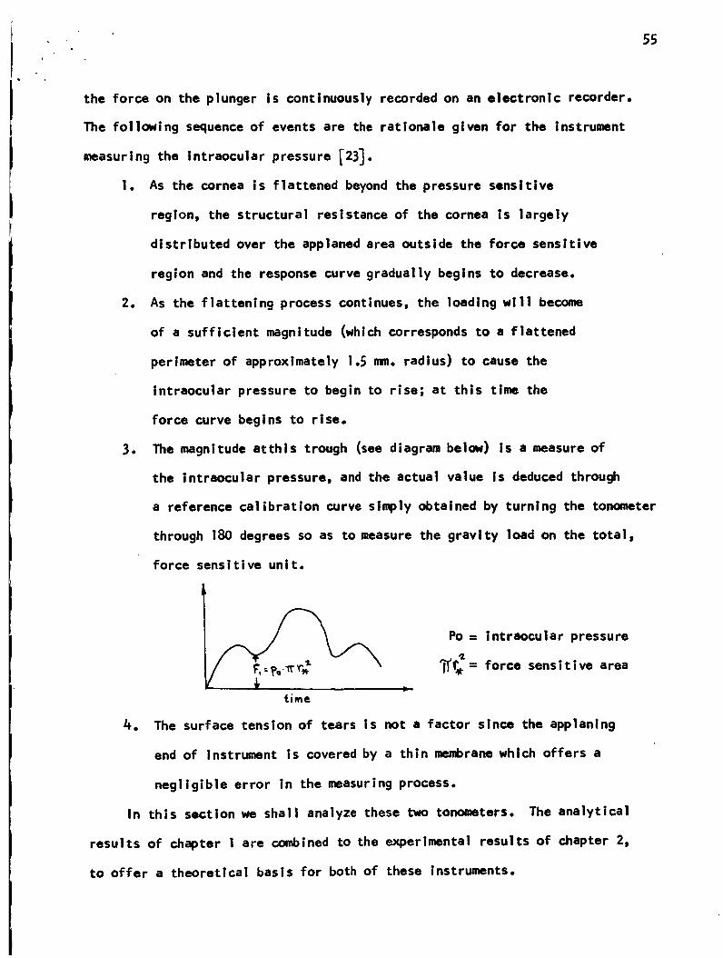
3. The magnitude atthis trough (see diagram below) Is a measure of
the intraocular pressure, and the actual value is deduced through
a reference calibration curve simply obtained by turning the tonometer
through 180 degrees so as to measure the gravity load on the total,
force sensitive unit.
Po= intraocular pressure
_= force sensitive area
4. The surface tension of tears is not a factor since the applanlng
end of Instrument is covered by a thin membrane which offers a
negligible error in the measuring process.
In this sectionwe shall analyze these two tonometers. The analytical
results of chapter 1 are combined to the experimental results of chapter 2,
to offer a theoretical basis for both of these Instruments.
56
3.4 A. The Goldmann tonomet;e r
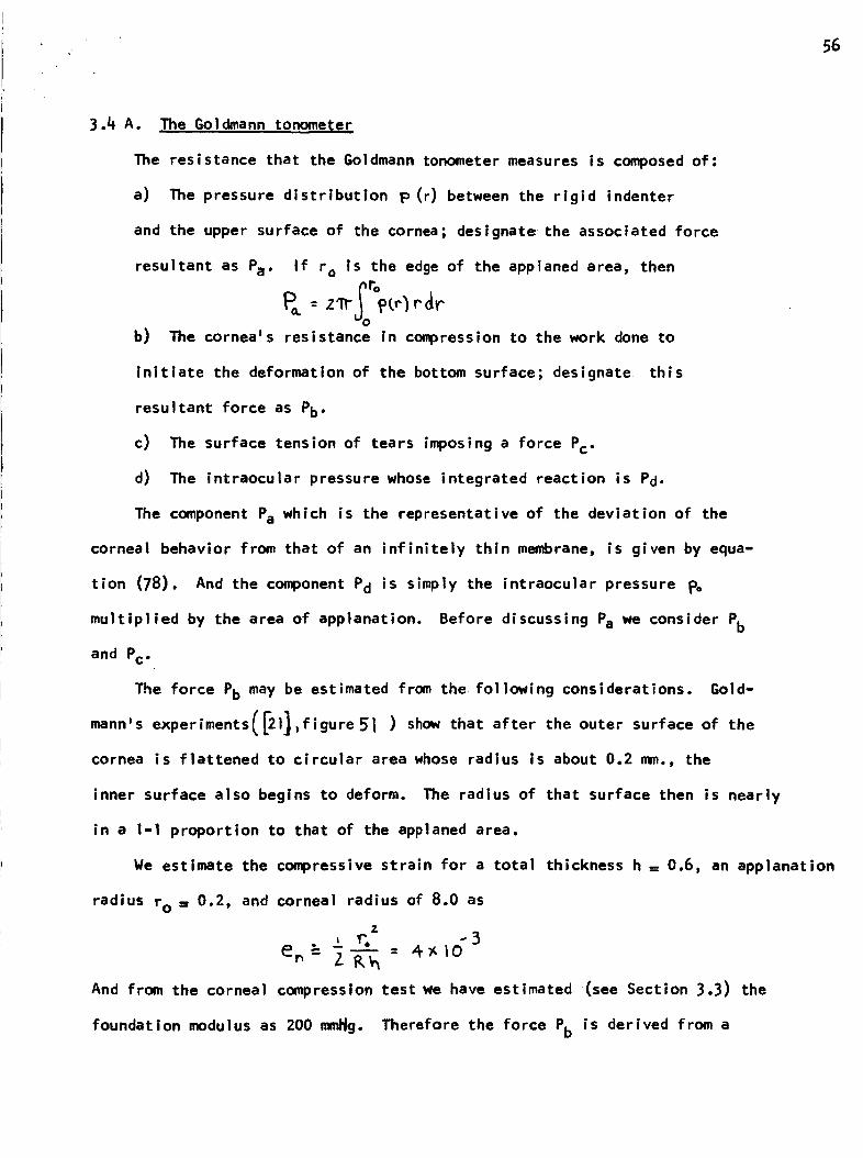
The resistance that the Goldmann tonometer measures is composed of:
a) The pressure distribution p (r) between the rigid indenter
and the upper surface of the cornea; designate the associated force
resultant as Pa" If r o is the edge of the applaned area, then
b) The cornea_s resistance in compression to the work done to
initiate the deformation of the bottom surface; designate this
resultant force as Pb"
c) The surface tension of tears imposing a force Pc"
d) The intraocular pressure whose integrated reaction is Pd.
The component Pa which is the representative of the deviation of the
corneal behavior from that of an infinitely thin membrane, is given by equa-
tion (78). And the component Pd is simply the intraocular pressure pc
multiplied by the area of applanation. Before discussing Pa we consider Pb
and Pc"
The force Pb may be estimated from the following considerations. Gold 1
mannls experiments(F2l],figure5 ( ) show that after the outer surface of the
cornea is flattened to circular area whose radius is about 0.2 mm., the
inner surface also begins to deform. The radius of that surface then is nearly
in a 1-1 proportion to that of the applaned area.
We estimate the compressive strain for a total thickness h = 0.6, an applanation
radius r O = 0.2, and corneal radius of 8.0 as
%
±_'. -3en" Z-_--_ = 4-y,_o
And from the corneal compression test we have estimated (see Section 3.3) the
foundation modulus as 200 mml_g. Therefore the force Pb is derived from a
57
resultant pressure in the neighborhood of about 0.8 mmHg.
The force Pc is very difficult to estimate since we must know the con-
tact radius for the tear-cornea-tonometer interface. However, the following
calculation indicates the order of magnitude of the force. With respect to
figure 30 _ let Rt be the radius of the fluid surface, in a plane parallel to
the tonometer, which has spread along the surface of the tonometer. Let r t
be the tear radius at the edge of the wetted area. Then the pressure drop across
the tear surface Is _ZT]
(, ,)where _ is the surface tension constant of tears. The contact angle, and
hence the radius r t depends, in part, on the spreading distance Rt. Hence
the tonometer surface and anesthetic are factors in the size of r t,
As the tonometer contacts the layer of tears on the cornea, a fluid
layer spreads over part of the tonometer surface. If the radius of curve-
2 2ture of the cornea is Rc, then if Rt<<R c, it follows that
" / /Pcand hence
( 87 )
The surface tension constant _k is known to be about. [ ref.14J 59 dynes/=.
So if Rt = 1.7 mm (a reasonable choice for an applanation radius of 1.5 mm) and
Rc = 8.0 ram., then
-- S.SS)C I0 Cmz
Hence the force Pc' at the contact area for Goldmann tonometry (Tl'(I.53)2mm2),
is approximately.415 grams. This resultant is directed along a normal into the
cornea and pulls the tonometer into the eye. Hence it tends to balance the
forces Pa and Pb"
58
Our analytical results Indicate that beyond a certain radius, the force
Pa ceases to increase, l.e., a form of elastic Instability manifests (see
section i.7). Now it is important to recall that our analytical solution
assumes no edge restraint, and we expect the solution to break down for some
flattened radius. (Probably beyond i.5 mm. _or a 12 mm. scleral radius, i.e.
the edge of shell about 8 diameters away from the loaded region). Also, since
we specify displacements in the loaded region, the solution applies for any
layer that flattens.
From figuresSI32we see that after the outer layer is flattened beyond
about 0.5 mm. (if its thickness is 0ol or 0.2 mm.), the force Pa no longer
increases° For that radius, the center layer has only flattened to about a radius of
0.3 mm., and the force Pb corresponds to a pressure less than 0.81,Wgo
Experimentally, _21_ , we know that for an applanation radius of 0.5 nn.,
the surface tension force often over balances the structural resistance. And
this is consistent with our analytical results even if the center layer is
0.6 n_. thick (see figure 36 and the estimates for Youngis modulus in section
Therefore, our explanation of the process of Goldmann applanation tono-
merry is as follows:
I. Up to a flattened radius of 0.5 n_. the structural resis-
tance of the cornea is due to its outer layer.
2. Beyond this radius, the resistance in compression and the
structural resistance of the central layer increase to balance
the surface tension force.
3. As flattening Increases, end effects come Into play and the
resistance continues to rise.
This explanation is consistent with Goldmann's observation [21] that
the instrument's accuracy does not depend on the level of intraocular pressure.
If the instrument were calibrated at, say, a 20mm.Hg. intraocular pressure,
and the pressure were raised to 60mm._lg., the cornea would be in a different
state of tension. And if there was no elastic instability in the rigid outer
layer, it is difficult to see how surface tension could balance the structural
resistance independ¢nt of the level of intraocular pressure.
Also, it is known [21] that wrinkles can be seen in DescemetJs mem-
brane during the applanation process; hence we have the experimental observa-
tion that at least Descemet_s membrane goes into an elastically unstable
_vHm i _l_l _1= mvHe
If the outer layer's structural resistance was monotone with an in =
creasing applanation radius, then our results indicate that for a 1.5 mm.
applanation radius, its structural resistance would be much higher than could
be balanced by surface tension. Noreover, in view of its rigidity, it is
difficult to see how the convenient 1.53 mm. applanation radius could be
found., and how this number could be the same for all eyes unless the corneal
resistance was very low beyond a certain applaned region.
Our analysis shows that the Goldmann tonometer has a very weak
dependence on the radius of curvature of the cornea. If the thickness of the
outer layer is nearly the same (say to within 15 percent) for all eyes, then
in view of the low modulus of elasticity of the central layer, the tonometer
is insensitive to variations in the overall corneal thickness of different
human eyes.
3.4 B The I_ckay-I_arq tonomcte_
The corneal resistance that the Nackay=Marg tonometer detects is
the same as that of the Goldmann tonometer until the flattened area exceeds
By 'tinsensltiveJl we mean that the Instrumentms response is changed by
|ess than ten per cent,
60
that of the force sensitive region. Let r o be the radius of the flattened
area and r_ the radius of the central, force sensitive plunger. Then the
force measured by the Nackay-Harg tonometer is composed of the following
factors:
a) The pressure distribution p(r) (between the rigid, applaning
surface and the upper surface of the cornea) integrated over2
the area_T' p_ . Let this component of the resultant force
be PI (ro;r_)"
b) The cornea's resistance in compression until the bottom
surface begins to deform; designate the force as P2 (ro)
0 I ....... = .....
P3 (r*) = PoI_ rw2.
d) The degree of co-planarity of the central plunger and the
remainder of the tonometer's surface. Let the plungerls extension
or insertion relative to a point on its surface, outside the
force sensitive area be e. And let Pe (ro;r .) be the measured
force arising from the deviation from co-planarity.
(*)The force PI (ro;rw) is given by
R(ro r.)= Irp(r r , p ro r, (88)O
The pressure distribution p (r) is given by equation (72) of Chapter 1, and
if we perform the above integration we have -
(_) The expressions assume pressure sensitivity over a central area. If this
area is disjoint from the outer applaning surface, then the membrane forces in
(72) are not measured for ro > r_.
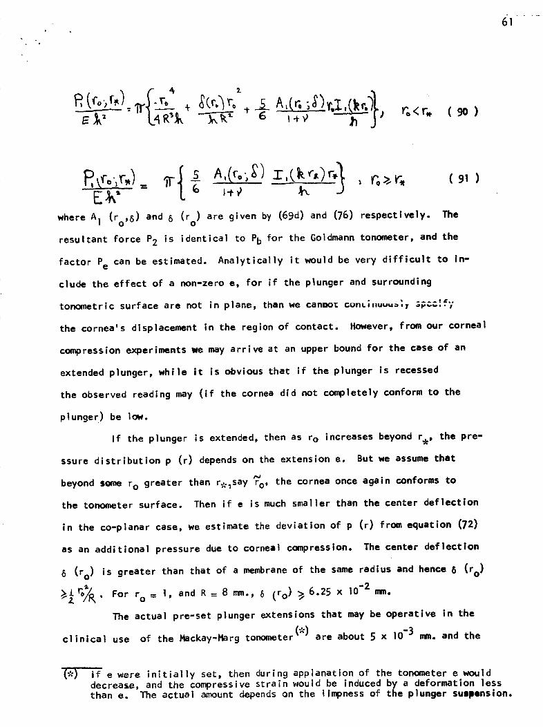
1 - L
Z ,5_ ;S)v'.I6 " I-t-_ ' ;r <r. ( 90 )
where A! (ro, 8) and 8 (ro) are given by (69d) and (76) respectively. The
resultant force P2 is identical to Pb for the Goldmann tonometer, and the
factor Pe can be estimated. Analytically it would be very difficult to in-
clude the effect of a non-zero e, for if the plunger and surrounding
tonometric surface are not in plane, than we cannot cunL;,,uuu=,_ _e.... ,
the cornea's displacement in the region of contact. However, from our corneal
compression experiments we may arrive at an upper bound for the case of an
extended plunger, while it is obvious that if the plunger is recessed
the observed reading may (if the cornea did not completely conform to the
plunge r ) be low.
If the plunger is extended, then as ro increases beyond rw, the pre-
ssure distribution p (r) depends on the extension e. But we assume that
beyond some ro greater than %_say r o, the cornea once again conforms to
the tonometer surface. Then if e is much smaller than the center deflection
in the co-planar case, we estimate the deviation of p (r) from equation (72)
as an additional pressure due to corneal compression. The center deflection
8 (r o) is greater than that of a membrane of the same radius and hence 8 (r o)
_7_" For r o = 1, and R = 8 n_n., 8 (ro) _ 6.25 x 10⁻² mm.
The actual pre-set plunger extensions that may be operative in the
(.)clinical use of the Hackay-Harg tonometer are about 5 x 10⁻³ mm. and the
(*) If e were initially set, then during applanation of the tonometer e woulddecrease, and the compressive strain would be induced by a deformation lessthan e. The actual amount depends on the limpness of the plunger sulpension.
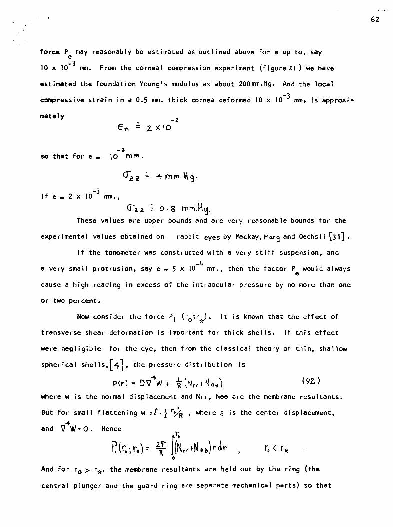
62
force P may reasonably be estimated as outlined above for e up to, saye
10 x 10 -3 mm. From the corneal compression experiment (figureZl) we have
estimated the foundation Young's modulus as about 200mm.ltg, And the local
compressive strain in a 0.5 ram. thick cornea deformed 10 x !0 -3 mm, is approxi-
mately -Z
-2
so that for • = I0 m m.
d-zz - 4mm. .
If e = 2 x lO "3 ram.,
_'t= " 0-8 mm._c_.
These values are upper bounds and are very reasonable bounds for the
experimental values obtained on rabbit eyes by Mackay, M=r3 and Oechsli _31].
If the tonometer was constructed with a very stiff suspension, and
a very small protrusion, say e = 5 x 10"4 mm., then the factor P would alwayse
cause a high reading in excess of the intraocular pressure by no more than one
or two percent.
Now consider the force Pi (ro;r_)° It is known that the effect of
transverse shear deformation is important for thick shells. If this effect
were negligible for the eye, then from the classical theory of thin, shallow
spherical shells,J4] , the pressure distribution is
P(r_ D9 4 (92)
where w is the normal displacement and Nrr, Nee are the membrane resultants.
But for small flattening w =_-_ =//R _ where 5 is the center displacement,
and _4W= O. Hence
T N,,*N,,)r r.o
And for r 0 > r_, the membrane resultants are held out by the ring (the
central plunger and the guard ring are separate mechanical parts) so that
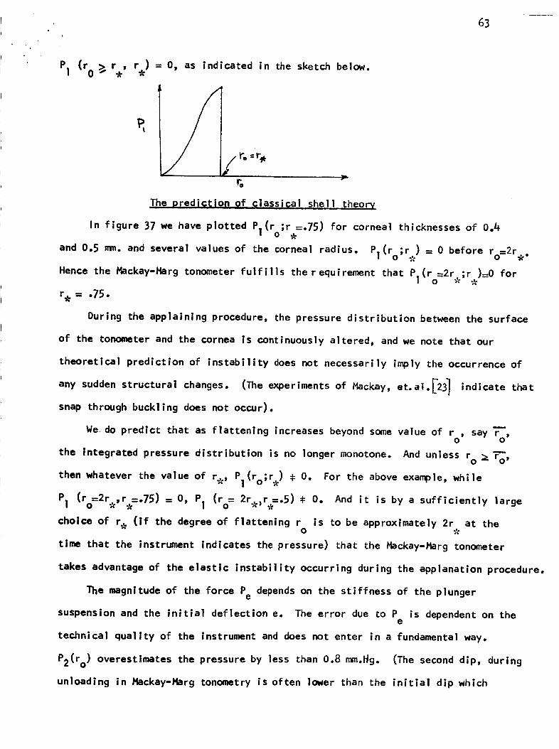
63
PI (ro >_ r , r ) = O, as indicated in the sketch below.
r.-_
r.
The predig_;ion Of qlassi_ai shell theory
In figure 37 we have plotted Pl(ro;r_-.75) for corneal thicknesses of 0.#
and 0.5 mm. and several values of the corneal radius. Pl(r ;r ) = 0 before ro=2r .0
Hence the Hackay-Harg tonometer fulfills the requirement that P1(ro=2r ;r )=0 fore
r_ = .75.
During the applainlng procedure, the pressure distribution between the surface
of the tonometer and the cornea is continuously altered, and we note that our
theoretical prediction of instability does not necessarily imply the occurrence of
any sudden structural changes. (The experiments of Hackay, et. al._2_ indicate that
snap through buckling does not occur).
We do predict that as flattening increases beyond some value of r , say 7-,O O
the integrated pressure distribution is no longer monotone. And unless r° _ ro,
then whatever the value of r_, Pl(ro;r ) # O. For the above example, while
PI (ro2re'r-_--'75) = O, PI (ro= 2r_r.--.5) # O. And it is by a sufficiently large
choice of r e (if the degree of flattening r is to be approximately 2r at theO
time that the instrument indicates the pressure) that the Hackay-Ptarg tonometer
takes advantage of the elastic instability occurring during the applanation procedure.
The magnitude of the force Pe depends on the stiffness of the plunger
suspension and the initial deflection e. The error due to P is dependent on thee
technical quallty of the instrument and does not enter in a fundamental way,
P2(ro) overestimates the pressure by less than 0.8 mm.Hg. (The second dip, during
unloading in Hackay-Harg tonometry is often lower than the initial dip which
64
Indicates the intraocular pressure. One reason for this Is that during
Ioadlng there Is some stress relaxation of the force P2(ro)| outflow is another.
The only theoretical limitation of the Hackay-Harg tonometer is the force
P2(r ) which causes an overestimate of the intraocular pressure. If the plunger0
extension was less than 2 x I0"3mm., then the Instrument's response is always
an upper bound for the pressure, and for a normal pressure of 16.0 mm.tttl. It
ylelds an error of less than 10%. As the intraocular pressure Increases, the
relative error decreases.
3.4C Summary of the Goiclmann afldttackav-Marq [Qllgmeters
The practical Ilmltations of the Goldmann tonometer appear to be more
severe than for the Flackay-I_rg tonomter. A 10 percent error in estimating
the radius of the epplanatlon area yields nearly a 20% error for the measured
pressure. Hence the skill of the opthaimologist during Golclmann applanation
tonoaetry is an Important factor. Also, the surface tension force has a strong
dependence on factors such as the condition of the surface of the tonometer
and the amount of fluid on the cornea before it is applaned. Either of the
factors: accuracy In judging the applanation area or a variability In the
surface tension could cause a high or a low reading.
The Hackay-Harg tonometer:s accuracy basically depends on the stiffness
and protrusion of the central plunger, if this factor is controlled (e.g.
employing a small, (e _ 2 x 10"3m.) positive protrusion and a stiff suspeasion,
then the Instrument ,ill always yleld an upper bound for the actual pressure,
measuring accurately to within 10 percent of the pressure. We note that due
to its weak dependence on YoungSs modulus, the Hackay-Harg tonometer should
yield good accuracy when applied on the sclera, which has a higher rigidity
than the cornea.
65
3.5 Indentation Tongmeters
In this section we shall discuss the Schlitz _onometer as representative
of instruments that indent the cornea under a constant force (_). The instan-
taneous, elastic response is measured in tonometry and during tonography the
time dependent response is measured for about four minutes. In
contrast to applanation tonometers, indentation tonometers, weighing 16.5 grams
in a typical clinical application, induce a rise in the intraocular pressure ,
and the magnitude of this induced pressure rise plays an important role in the
theory of the Schi_tz tonometer. During tonography, the fluid outflow is
altered and the induced pressure rise depends on the loading, geometry, material
properties and the change In the rate of fluid outflow. Figure (38) illus-
trates a portion of the cornea under a Sdh_tz lx_nometer.
The deformation of the cornea probably exceeds I/3 its thickness and hence
the elastic solution is beyond the scope of the geometrically linear theory
(small displacements as well as infinitesimal strains) of thin elastic shells.
But we are not so concerned with predicting the magnitude of the elastic response
as we are with its functional dependence on the intraocular pressure and the
material properties of the cornea. And we have shown that for a fixed intra-
ocular pressure the cornea conforms to the requirements of the Boltzmann
superposition principle. Thus a correct elastic solution in conjunction
with the correspondence principle of linear viscoelasticity would yield the
time dependent solution (The level of strain in the cornea during the appli-
cation of a Schi_tz tonometer with a 5.5 gram plunger load is probably less than
5 per cent.)
(_) The cornea is loaded by two concentric cylinders. The curvature and loadof the central cylinder, the plunger, is such that its total surface contactsthe cornea; the total surface of the outer cylinderD the foot-plateD does notcontact the cornea. The applied pressure of the plunger is greater than that ofthe foot-plate and the plunger deformation relative to the foot-plate is measured.The problem is a combined fixed (the plunger contact radius) and free (footplatecontact radius) boundary value problem. (see p.71,72,below)
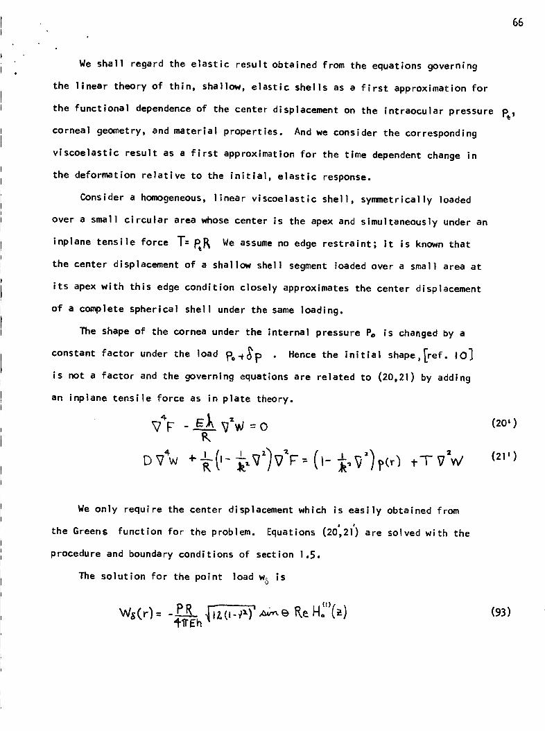
We shall regard the elastic result obtained from the equations governing
the linear theory of thin, shallow, elastic shells as a first approximation for
the functional dependence of the center displacement on the intraocular pressure pe _
corneal geometry, and material properties. And we consider the corresponding
viscoelastic result as a first approximation for the time dependent change in
the deformation relative to the initialp elastic response.
Consider a homogeneous, linear viscoelastic shell, symmetrically loaded
over a small circular area whose center is the apex and simultaneously under an
inplane tensile force T: _ We assume no edge restraint; it is known that
the center displacement of a shallow shell segment loaded over a small area at
its apex with this edge condition closely approximates the center displacement
of a complete spherical shell under the same loading.
The shape of the cornea under the internal pressure Pe is changed by a
constant factor under the load _o_p • Hence the initial shape,_ef. I0]
is not a factor and the governing equations are related to (20,21) by adding
an inplane tensile force as in plate theory.
4
P,,
66
(20')
= (21')tTVd
We only require the center displacement which is easily obtained from
the Greens function for the problem. Equations (20_21') are solved with the
procedure and boundary conditions of section 1.5.
The solution for the point load w6 is
(93)
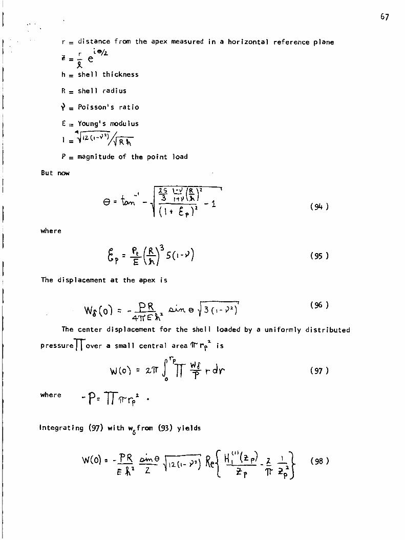
r = distance from the apex measured in a horizontal reference plane
r [ e/_.i_=-- e
h = shell thickness
R = shell radius
= Poisson's ratio
E = Youngls modulus
P = magnitude of the point load
But now
where
I I;g;? -_
The displacement at the apex is
(94)
(95)
The center displacement for the shell loaded by a uniformly distributed
pressure'S'over a small central area ql_rp _ is
0
where -P:T/-_¢ •
(98)
Integrating (97) with w6from (93) yields
f r,.J) nE_' z _r
67
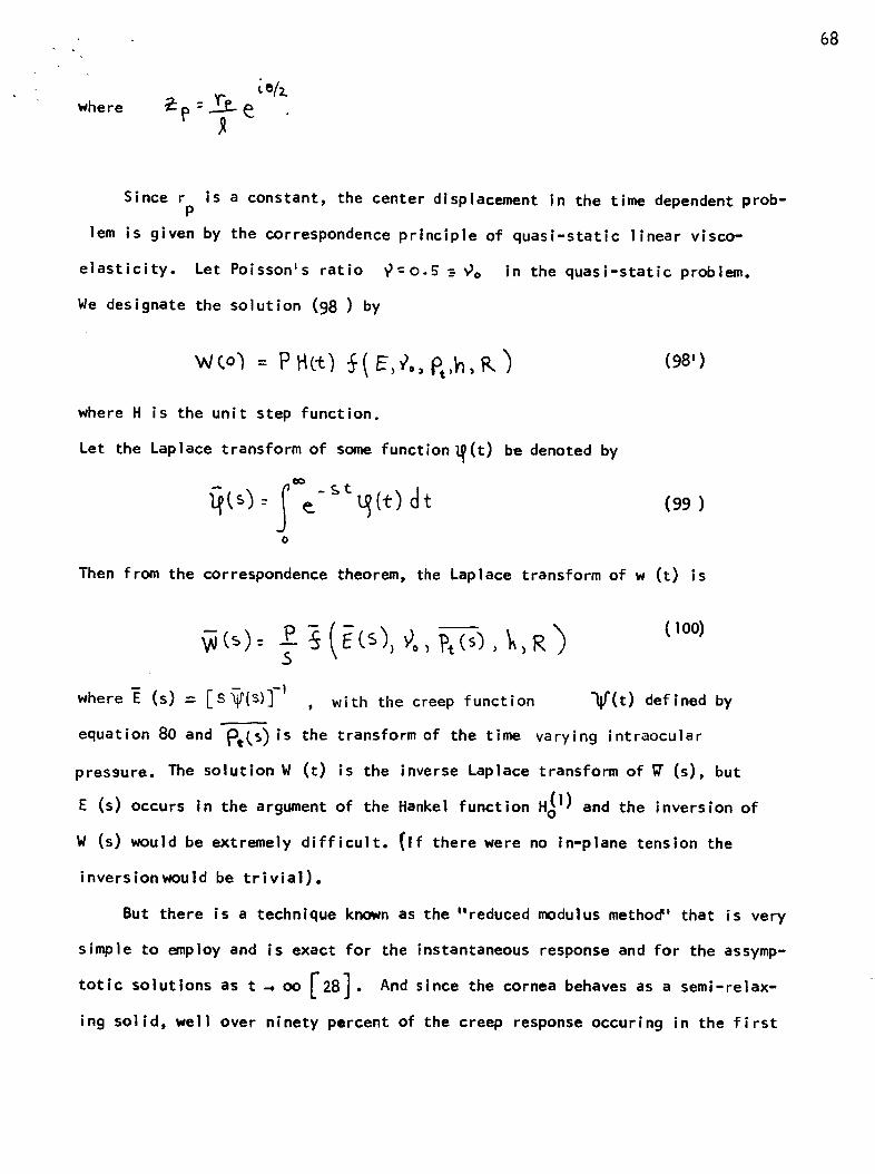
where
R
68
Since r is a constant, the center displacement in the time dependent prob-P
iem is given by the correspondence principle of quasi-static linear visco-
elasticity. Let Poisson's ratio _:o.5 _ _o in the quasi-static problem.
We designate the solution (98) by
(98')
where H is the unit step function.
Let the Laplace transform of some function _(t) be denoted by
o
(99)
Then from the correspondence theorem, the Laplace transform of w (t) is
.S ) ) )
where "E (s) = [S_Is)] -I , with the creep function
(loo)
"_j'(t) defined by
equation 80 and "_e(s) is the transform of the time varying intraocular
pressure. The solution W (t) is the inverse Laplace transform of _ (s), but
occurs in the argument of the Hankel function H_ i) and the inversion ofE (s)
W (s) would be extremely difficult. (If there were no in-plane tension the
inversionwould be trivial).
But there is a technique known as the "reduced modulus method' that is very
simple to employ and is exact for the instantaneous response and for the assymp-
as t 400 _28]. And since the cornea behaves as a semi-relax-totic solutions
ing solid, well over ninety percent of the creep response occuring in the first
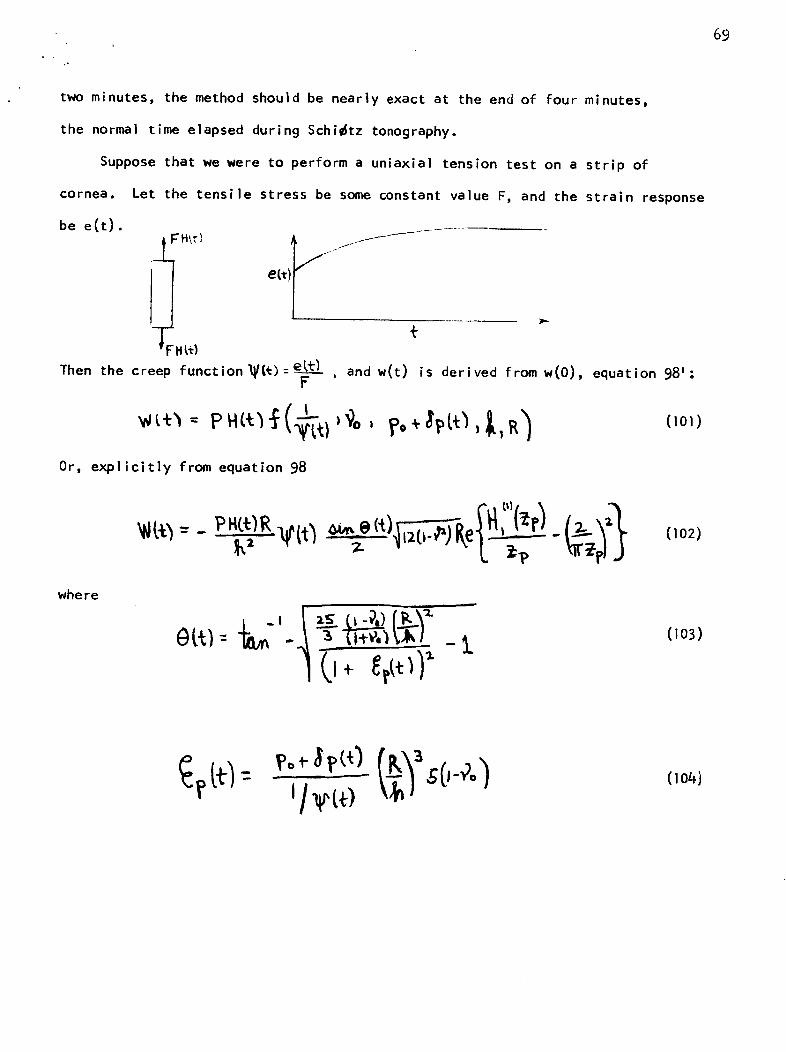
69
two minutes, the method should be nearly exact at the end of four minutes,
the normal time elapsed during Schi_tz tonography.
Suppose that we were to perform a uniaxial tension test on a strip of
cornea. Let the tensile stress be some constant va]ue F, and the strain response
be e(t).
Ht_)
Then the creep function_(_)=e_)F
, and w(t) is derived from w(O), equation 98':
(lOl)
Or, explicitly from equation 98
(io2)
where
= Zl£'- (lo3)
'l 'to- sO-Oo)(1o4)
70
w(4 minutes)For the two human eyes (same person) tested (figures 9,10), W(O) = °33
w(4)=.s3,and 0.33 respectively, and for the hog eyes (figures 11,12, 13 )
.44, and .39 respectively. Creep, for the human eyes, would account for a
30 percent increase in the measured Schlitz deformation at constant internal
pressure.
Before discussing the solution we relate the pressure po ÷ _L_
to the fluid flow out of the anterior chamber and into the canal of Schlemm.
The flow problem is very complex and it serves no useful purpose to attempt to
characterize it more accurately than the present approach taken by opthalmolo-
gists,_291. It is basically a low Reynold=s number porous media flow, and
often (see article by Scheidegger,[30]) a linear relationship exists between
the pressure drop and the flow rate. Since the porosity of the media (the
trabecular meshwork) has not been measured, to say nothing of its possible
dependence on the level of the intraocular pressure at any instant, it is best
to characterize the flow problem in terms of pressure gradiants across certain
"res i stances".
Let the flow rate out of the anterior chamber be Qa and the in-flow rate
be qp. Let the pressure drop out of the anterior chamber be _PA.c. and
the pressure gradiant allowing the fluid to flow from the posterior chamber be
Z_l)p.c. . Define resistance coefficients _ and B by
Qa = !AP=.c (105)
Then in steady flow, Qa = Qp so that
(I06)
71
oL
(107)
And we can distinguish several cases relative to normal values _N' BN"
a) B = BN ' _ >:>_N ... open angle glaucoma
b) B_< BN , c_=_ N ... perhaps a form of hypersecretion glaucoma
The pressure drop _P_c is the difference between the venous pressure Pv
and the anterior chamber pressure Pt" Therefore
Pt = Pv + _ Qa
and equation (104) becomes
The initial measured response of the Shi_tz tonometer is the relative
deformation of the plunger and the guard ring. Therefore the initial reading
has a more complex parametric representation than (98) including the weight of
the foot plate, and the radiuspf with which the foot plate contacts
the cornea. The radius pf itself depends on the load) internal pressure and
the material behavior. So the elastic solution (98) basically shows us the least
complex way that th_ level of intraocular pressure affects the measured response.
We see that the level of pressure, creep and geometry enter non-linearly, and
a small change in these variables would not yield a proportional change in de-
formation. Hence it is not difficult to understand how the Schi_tz _onometer
can be quite sensitive to |ntraocular pressure changes.
The sensitivity is illustrated by the behavior of the Greens function
(93) at the apex. There is a strong dependence on the magnitude of P/E, the
.. 72
sensitivity to pressure changes being greater for smaller Youngms modulus.
(See the experimental results, figures 16-20). In a certain range of the value
P/E, the instrument may be quite sensitive to the value of R/h.
Now the correspondence principle of linear viscoelasticity only applies
If the boundary conditions In the elastic and viscoelastic problems are the
same. But during tonography, the area of contact between the footplate and
the cornea changes and our solution indicates an over simplification of the
relative change in time between the footplate and the plunger.
The solution (102) shows that the change in the measured response of the
Schlitz tonometer may have a basic dependence on two quantities: the creep
functionV(t) and an expression that we denote by_t(t).
floql
Horeover, we see that the material properties, (represented by the creep
function_(P) and the level of intraocular pressure (or the fluid outflow) are
linked by the parameter/b((t). And a possible inference from this parametric
dependence is illustrated by the following situation. Suppose Schlitz
tonography were performed on the eyes of two people, and the resulting tonograms
were different. Then the difference could be due to not only their respective
outflow resistances, but to a difference in their creep functions.
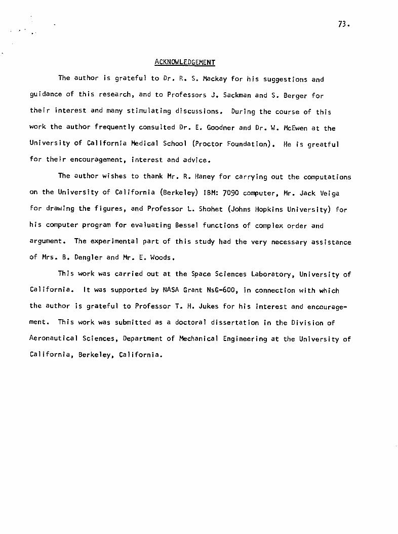
73.
ACKNOWLEDGEMENT
The author is grateful to Dr. R. So Mackay for his suggestions and
guidance of this research, and to Professors J. Sackman and S. Berger for
their interest and many stimulating discussions. During the course of this
work the author frequently consulted Dr. E. Goodner and Dr. W. McEwen at the
University of California Medical School (Proctor Foundation). He is greatful
for their encouragement, interest and advice.
The author wishes to thank Mr. R. Haney for carrying out the computations
on the University of California (Berkeley) IBM: 7090 computer, Mr. Jack Veiga
for drawing the figures, and Professor L. Shohet (Johns Hopkins University) for
his computer program for evaluating BesseI functions of complex order and
argument. The experimental part of thls study had the very necessary assistance
of Mrs. B. Dengler and Mr. Eo Woods.
This work was carried out at the Space Sciences Laboratory, University of
California. It was supported by NASA Grant NsG-6OO, in connection with which
the author is grateful to Professor T. H. Jukes for his interest and encourage-
ment. This work was submitted as a doctoral dissertation in the Division of
Aeronautical Sciences, Department of Mechanical Engineering at the University of
California, Berkeley, California.

.. REFERENCES
1. Timoshenko, S. and Guodier, J.N., Theory of Elasticity , Ch. 13; McGraw-
HIll Book Co., 1954.
2. Essenburg, F., a_ On Surface Constraints in Plate Problems, " J. Appl. Mech.,
p.340, ppo340-44, June 1962.
3. Reissner, E._ " The Effect of Transverse Shear Deformation on the Bending
of Elastic Plates," J. ADDi t Mech., v.12, pp.69-77, 1945.
4. Reissner, E., " Stresses and Small Displacements of Shallow Spherical Shells, "
I, J.Math. Phys., pp.80-85_ v.25,1946.
5. Reissner_ E., "Stresses and Small Displacements of Shallow Spherical Shells, "
II, J. Math, Phys., pp.279-300, v.25, 1946.
6. Naghdi _ P.M., " On the Theory of Thin Elastic Shells, " quart. AppI. Math.,
vol. xiv, no. 4_ pp. 369=80, 1957.
7. Naghdi, P.H., " Note on the Equations of Shallow Elastic Shells, " _uart,
A_pl. Math_, vol. xiv, no.3 , pp. 331-33, 1956.
8. Love, A.E.H., A Treatise on the Mathematical Theory of Elasticity , Ch. xxiv,
Dover Publications, fourth ed., 1927.
9. Green, A.E. and Zerna, W., _Theoretical Elasticity , Ch. xi, Oxford Press, 1954.
10. Fung,Y.C. and Sechler, E.E., " Instability of Thin Elastic Shells, " Proc.
_irst Synt)_ Naval Structural Mech., Pergamon Press, pp.115-68, 1960.
li. Mc Lachlan,N.W., Bessel Functions for Enqineers, second ed., Oxford Press, 1955.
12. Ince,E.L., Ordinary Differential Equations, Dover Publications, first ed., 1926.
13. Donneli, L.H., " Shell Theory, " 4 th Nidwestern Conference on Solid Mechanics,
Univ. of Texas, 1959.
14. Cerrano,E., " Ricerche Fisico- Chimiche suile Lacrime in Relazione alia dei
Collirii, " ArChivio di Farmacoloqia Sperimentalle e Sgienze Affine, v.8, 1909.
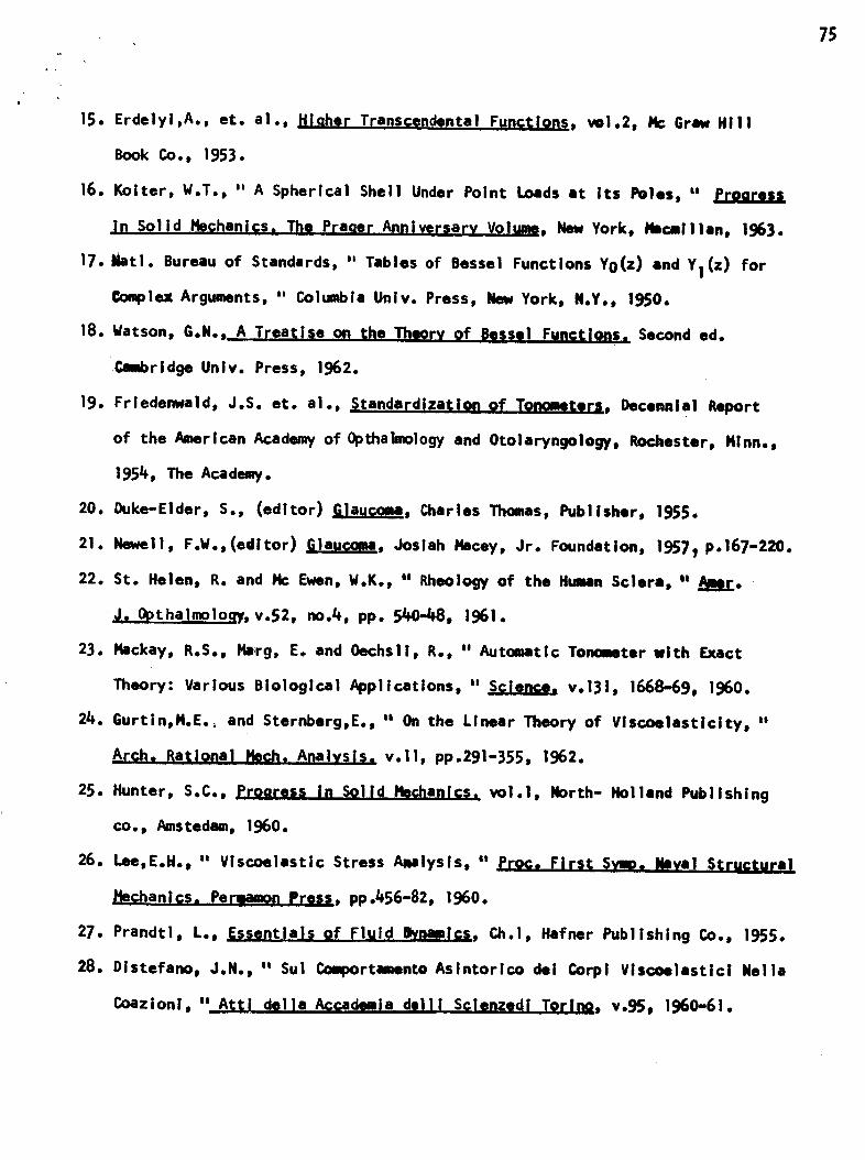
15. Erdelyi,A., et. al., Hiaher Transcendental Functlon_, vol.2, Nc Grew Hill
Book Go., 1953.
16. Koiter, W.T., " A Spherical Shell Under Point Loads at its Poles, "
in Solid Hechanics. The Praqer Annlversarv Volta, New York, Macaillan, 1963.
17. Natl. Bureau of Standards, " Tables of Bessel Functions Yo(z) and YI (z) for
Complex Arguments, " Columbia Univ. Press, Hew York, N.Y., 1950.
18. Watson, G.N., A Treatise on the Theory of Bessei Functions. Second ed.
Cmbridge Univ. Press, 1962.
19. Frledenwald, J.S. et. al., Standardization of Tonometers, I)ecennlal Report
of the American Academy of 0pthaimology and Otolaryngology, Rochester, Hlnn.,
195/+, The Academy.
20. Duke-Eider, S., (editor)Glauc_, Charles Thomas, Publisher, 1955.
21. Hawaii, F.Wo,(edltor) Glaucoma, Josiah Hacey, Jr. Foundatlon, 1_7_ p.167-220.
22. St. Helen, R. and I%= Ewen, W.K., " Rheology of the Human Sclera, " Ajlr.
J. Opthalmoloqy, v.52, no.L_, pp. 544]-48, 1961.
23. Mackay, R.S., Harg, E. and Oechsii, R., ,e Automatic Tonometer with Exact
Theory: Various Biological Appllcations, " Science, v.131, 1668-69, 1960.
2L_. Gurt|n,H.E.; and Sternberg,E., " On the Linear Theory of Viscoelasticity, ':
Arch. Rational Hech, Al_a_ysis. v.ll, pp.291-355, 1962.
25. Hunter, S.C., Prooress In Solid HechaniG,,;. voi.I, North-Holland Publishing
co., Amstedam, 1960.
26. Lee,E.H., " Viscoelastic Stress ANlysis, " _Proc. First SVUD. NIIyal Sf;ructural
Hechanlcs. PerllamOrl Press, pp._56-82, 1960.
27. Prandtl, L., Essentials of Fluid Bvnamlcs , Ch.i, Mafner Publishing Ca)., 1955.
28. Distefano, J.H., " Sul Goqmrtamento Asintorlco dei C4)rpi Viscoelestici Helle
Goazionl, " Atti della Accademla delli Sclenzgdi TorJl_o, v.95, 1960-61.
75
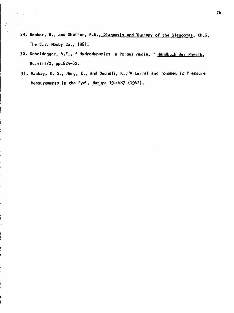
-. 76
29. Becker, B., and Shaffer, R.N.,.. Diaqnosis and Therapy qf _;he Glaucomas, Cho6,
The C.V. Mosby Co., 1961.
30. Scheidegger, A.E°, i, Hydrodynamics in Porous Hedia_ _' qandbuch der Physik,
Bd.vii i/2_ pp°625-62.
31. Hackay, R. S., Harg, E., and Oechs||_ R.,"Arterial and Tonometric Pressure
Heasurements In the EyeH, Nature 194:687 (1962).
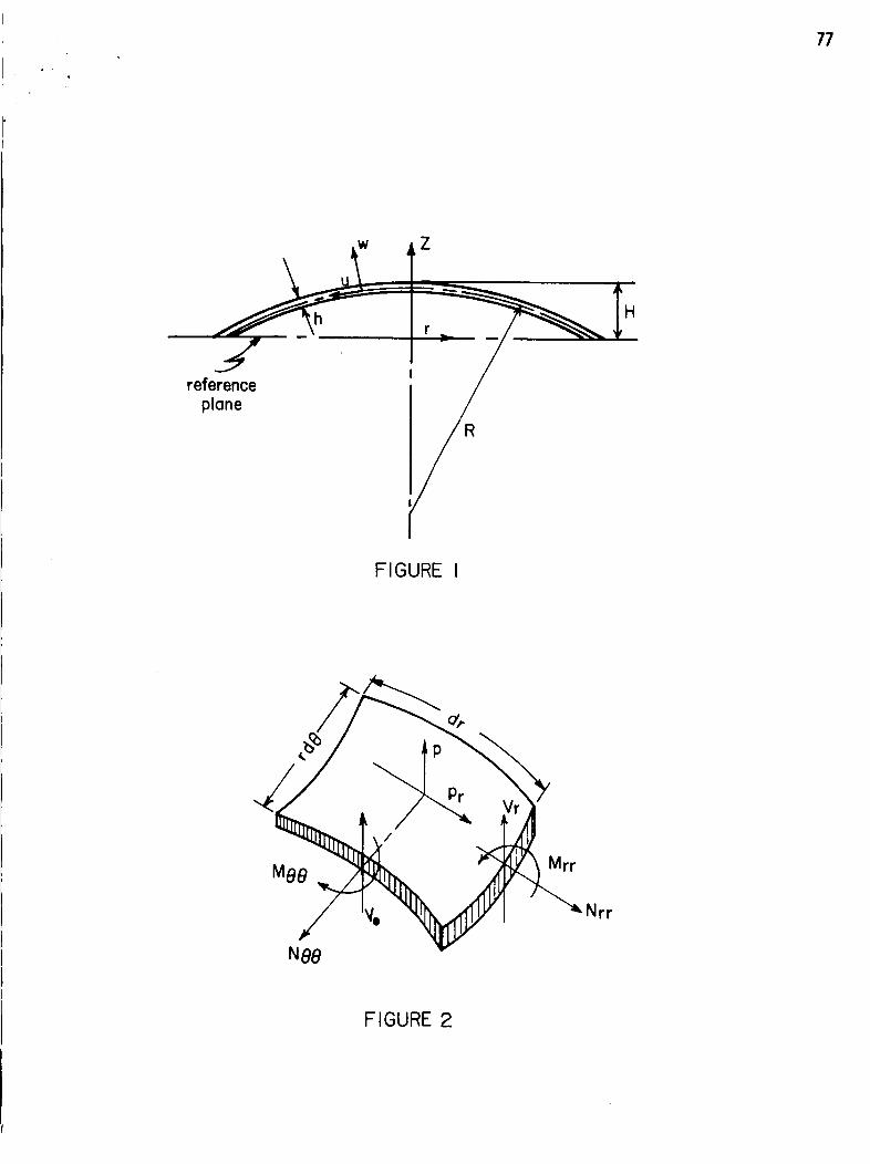
77
Z
reference
plone
R
FIGURE I
Nrr
N88
FIGURE 2
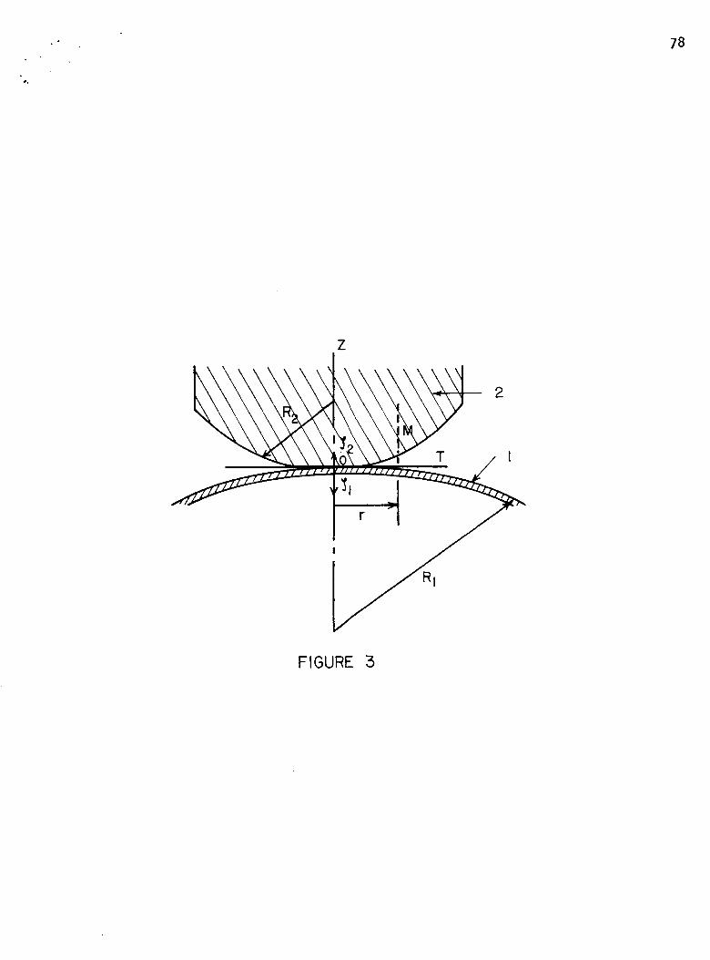
-" 78
Z
I
T
RI
FIGURE 3
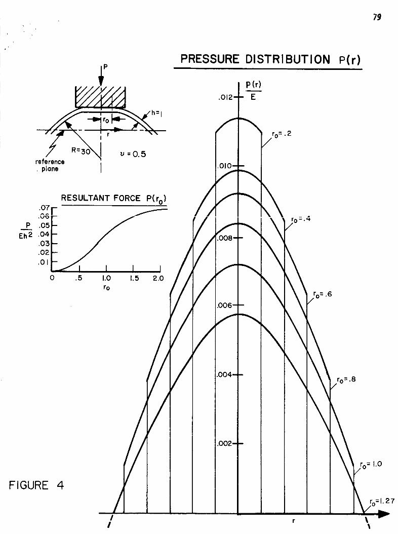
79
referenceplane i
PRESSURE DISTRI BUT ION
P(r)
.012- - E
f_
: 2/to •
i
RESULTANT FORCE P(rO) /_ f_^_l-
P .05
E_ .04.03
.02
.01I
0 .5 1.0 1.5 2.0
ro.6
//FIGURE 4
/I
!
P(r)
/
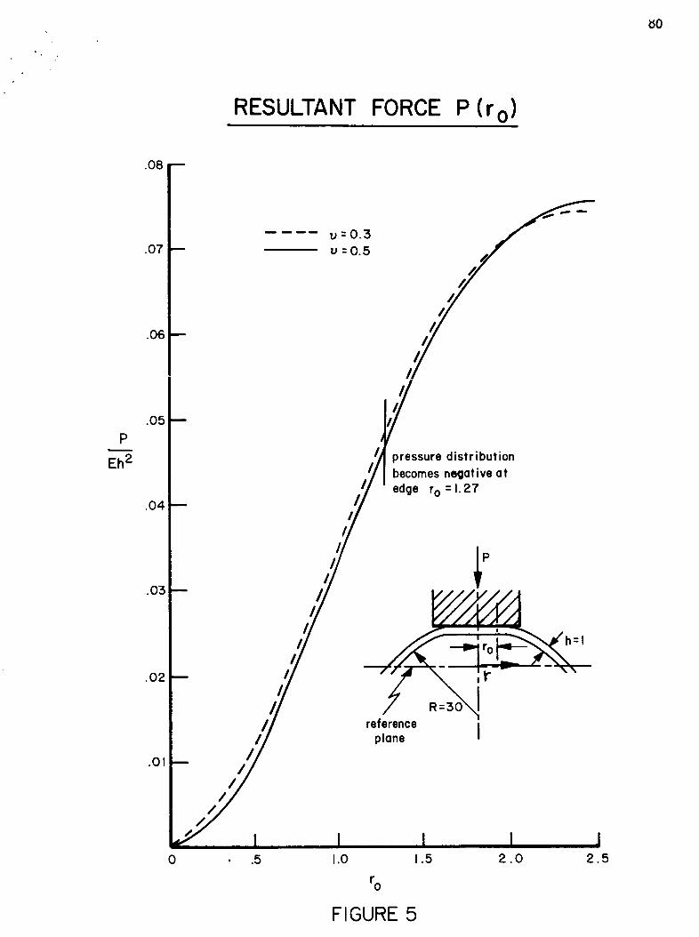
80
RESULTANT FORCE P (r o)
.O8
.O7
.O6
u=0.3
u=0.5
P
Eh 2
.o5
.o4
.o3
.02
.01/
/
pressure distribution
becomes negative at
edge ro=1.27
referenceplane J
0 •5 1.0 1.5 2.0 2.5
ro
FIGURE 5
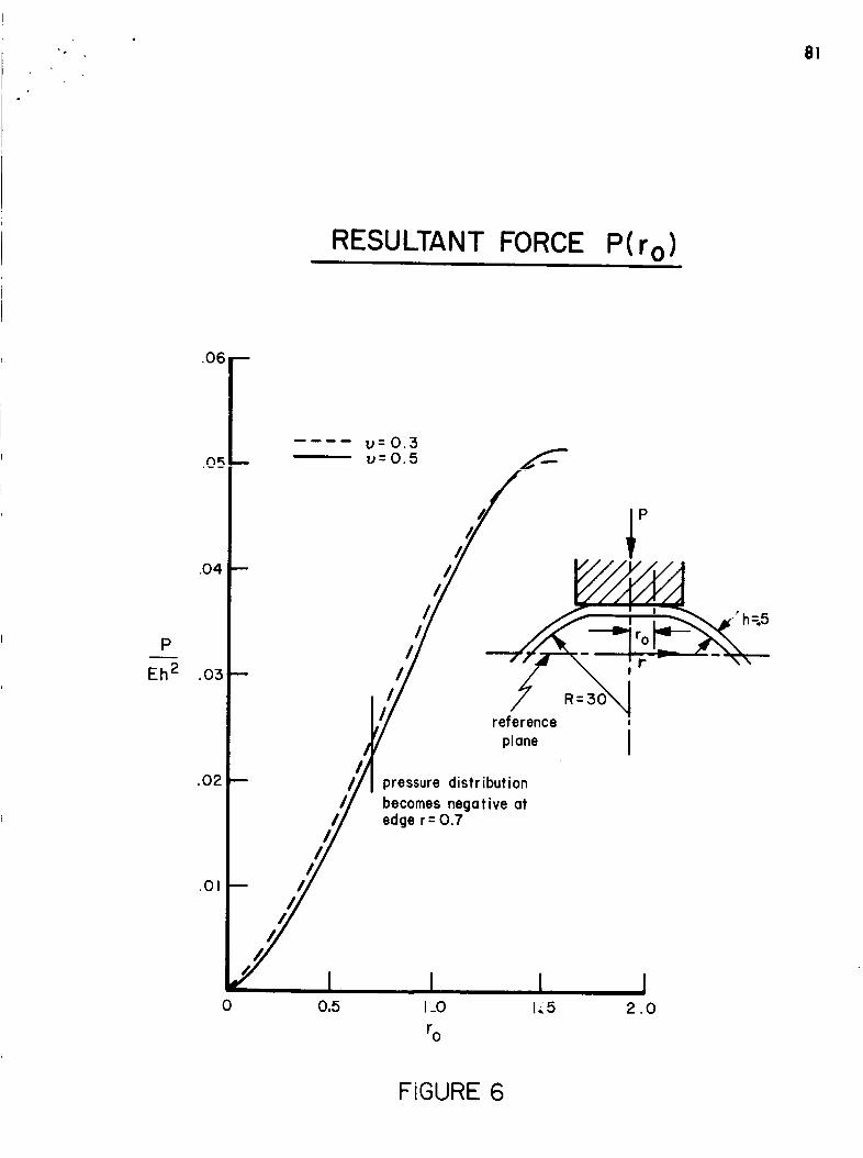
RESULTANT FORCE P(r o)
.06 --
u=0.3u=0.5
P
Eh 2
.02
reference
plane J
pressure distribution
becomes negative atedge r = 0.7
.01
0 0,5 1.0
ro
1-,,5 2.0
FIGURE 6
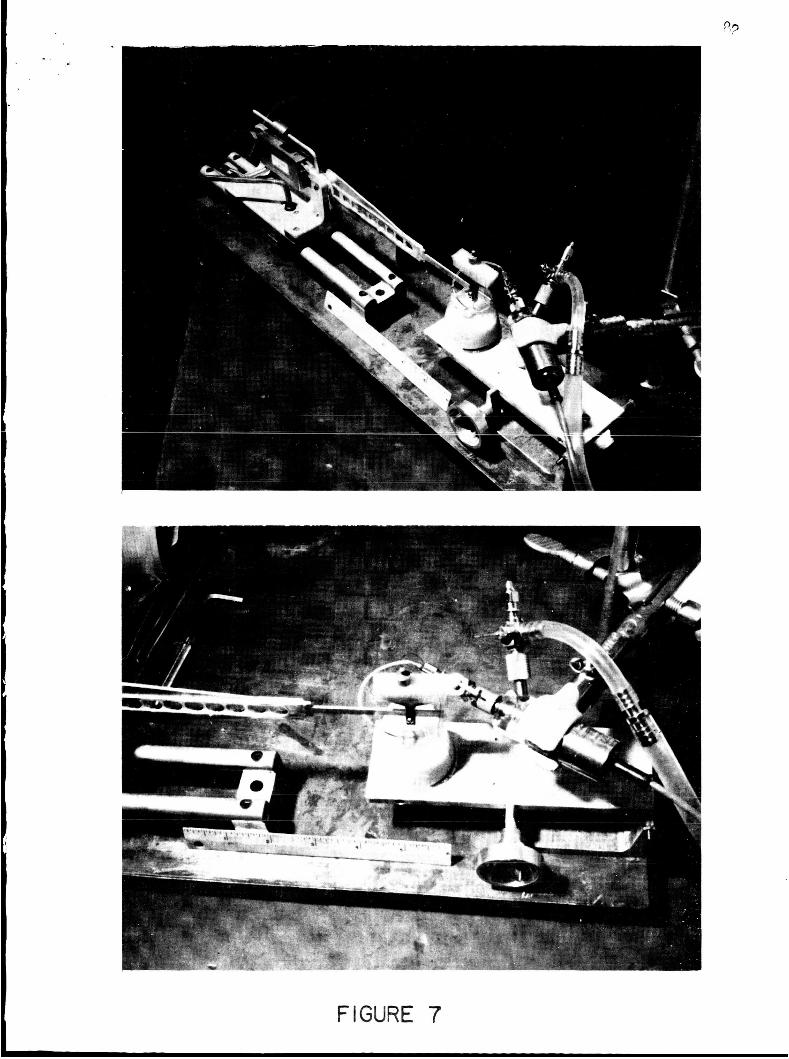
..
FIGURE 7
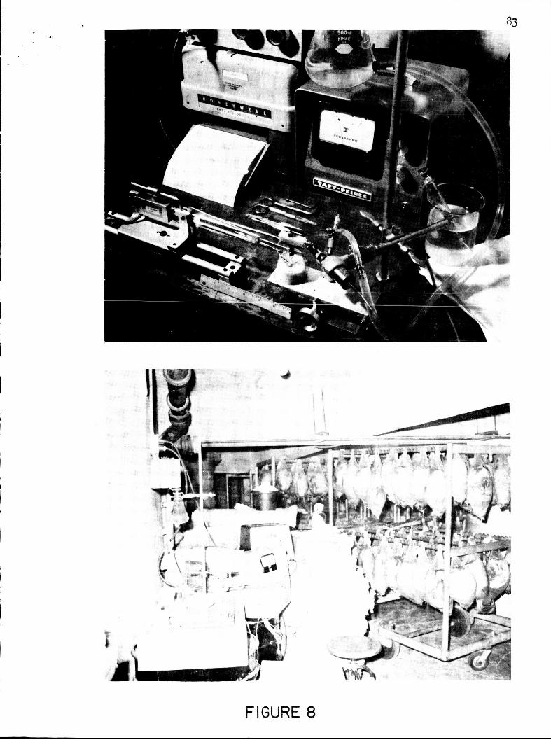
FIGURE 8

84
HUMAN EYE no. IAGE
DEATH
ENUCLEATED
TESTED
PRESSURE
RADIUS
ROOM TEMP
70 years
2:00 a.m.
7:30 a.m.
11=30a.m.
40 mm. rig
7.5 mm
70 ° F
.65 --
SUPERPOSITION
0 I 2 3
82
I I I4 5 6
z
"50
n,"0u_ .25LIJ(3
00
83"11.2 g. load
CREEP TEST
82 " 7. 2 g. load
81":3.2 g.load
f
I2
I5
TIME IN MINUTES
FIGURE 9
I I I4 5 6
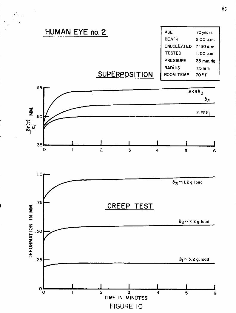
85
HUMAN EYE no. 2
SUPERPOSITION
AGE
DE AT H
ENUCLEATED
TESTED
PRESSURE
RADIUS
ROOM TEMP
70 years
2:00 a.m.
7:30a.m.
I: O0 p.m.
:35 mm.Hg
7.5ram
70 = F
0
.64383
82
2.2581|
I I I I I II 2 3 4 5 6
.75
_E
z
.50=Err0i,ILla
.25
1.0 B
m
n
f
00
83"-11.2 g. load
CREEP TEST
82 " 7. 2 g. loadI
81 ".' 3.2 g. load
I2
, I:5
TIME IN MINDTES
FIGURE I0
I I 14 5 6
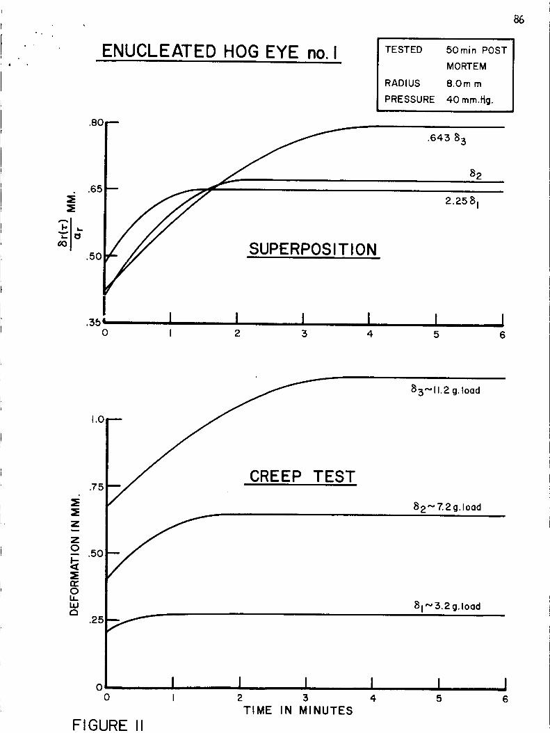
ENUCLEATED HOG EYE no. I TESTED
RADIUS
PRESSURE
50rain POST
MORTEM
8.0m m
40 mm.l_g.
.80 --
.65
.50SUPERPOSITION
.643 83
82
I.3_, I I I I
0 I 2 3 4I5
I6
z
.50
n-OI.n,.LUa
.25
1.0
EST.75
>........-
83"'11. 2 g. load
82'_ 7.2 g.load
o I I I I0 I 2 3 4
TIME IN MINUTES
F IGURE II
81 '_'3.2 g.load
I5
I6
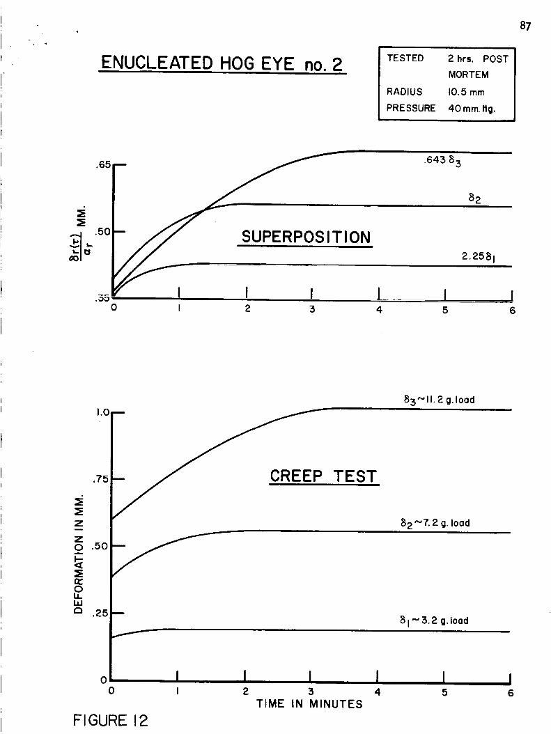
ENUCLEATED HOG EYE no. 2 TESTED 2 hrs. POST
MORTEM
RADIUS 10.5 mm
PRESSURE 40mm. ltg.
87
'5F
suP,,POS,T,ON.35 I I I l I I
0 I 2 3 4 5 6
1.0
.7'5
Z
_) .50
=Enr0LI.LIJ
.25
00
m
TEST
i
85"11.2 g. load
B2"7. 2 g. load
8 1"5.2 g.load
f
, I I I II 2 3 4
TIME IN MINUTES
FIGURE 12
J6
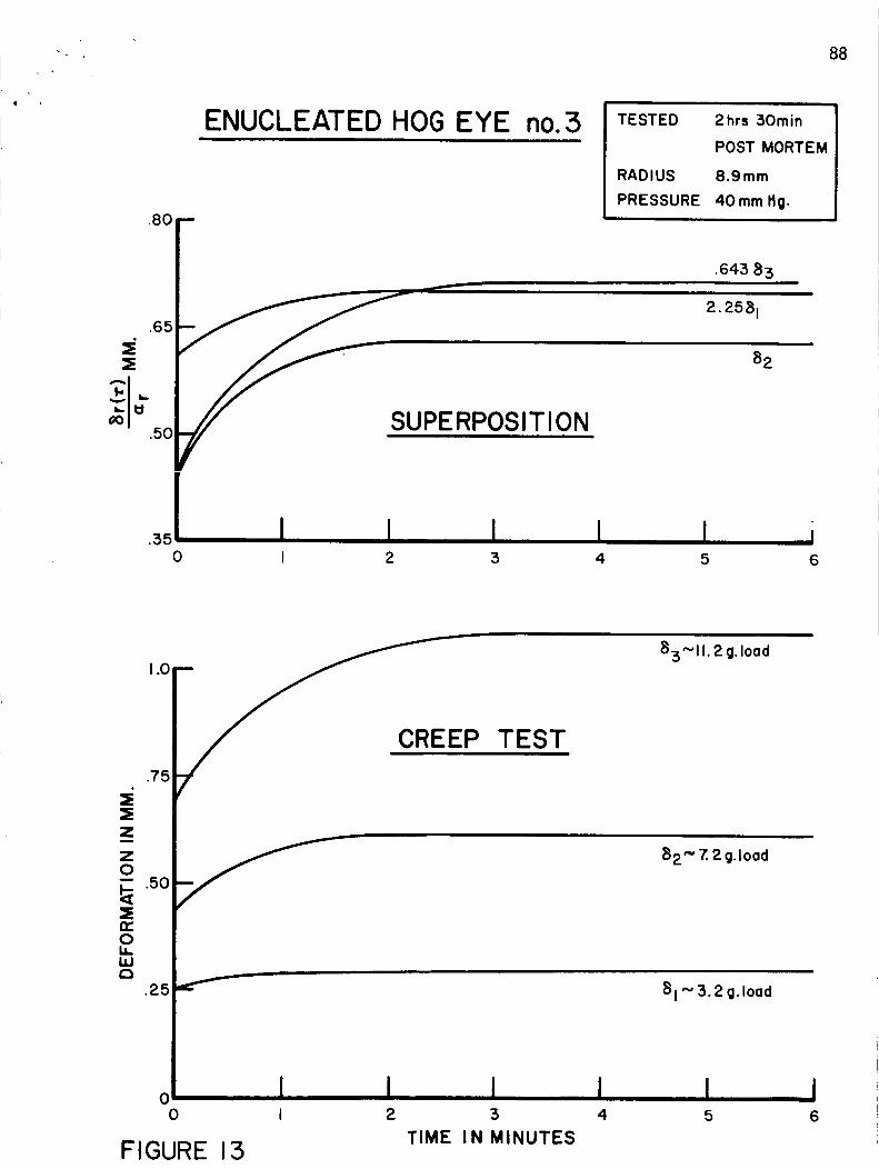
88
ENUCLEATED HOG EYE
.8oj_.65
_ 50 PERPOSITION
TESTED
i4
2hrs 30rain
POST MORTEM
RADIUS 8.9ram
PRESSURE 40ram fig.
.643 83
.351 I i0 I 2 3
82
I6
1,0
.7 =,
.=Z
.5(=En-OI.i.I.iJf-t
.25
00
i
EP TEST
83"1 I. 2 g. load
82" Z 2 g.load
FIGURE 13
81 "' 3.2 g.load
I I I2 3 4
TIME IN MINUTES
I5
I6
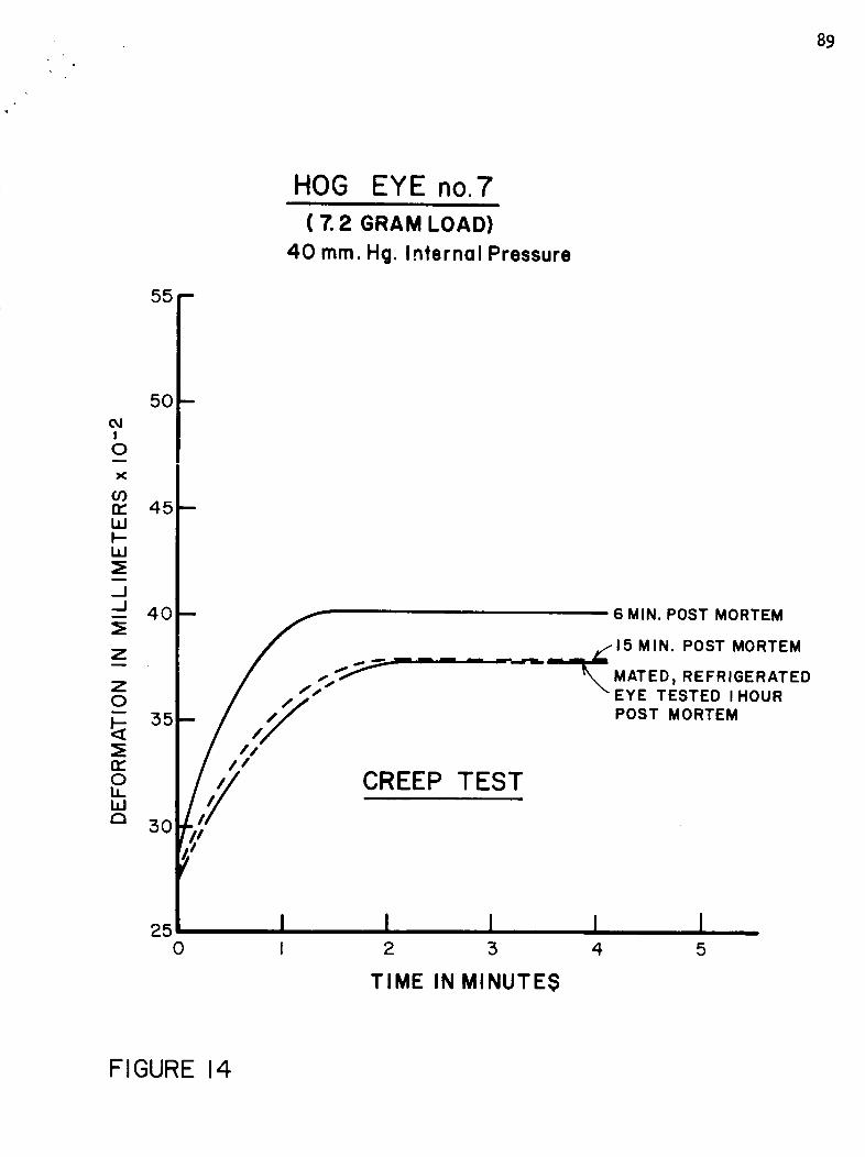
89
55
HOG EYE no.7
( 7. 2 GRAM LOAD)
40 ram. Hg. Internol Pressure
I0
or)n-LLII--LLI
--I.--I
Z
5O
45
40 6 MIN. POST MORTEM
=,.,..,/'15=_ MIN. POST MORTEM
S3,5 POST MORTEM
n," /o CREEP TESTLLLLI
50
250 I 2 3 4 5
TIME IN MINUTES
FIGURE 14
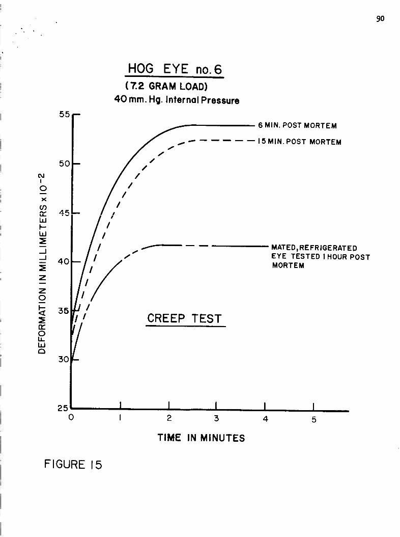
9O
HOG EYE no. 6
( 7.2 GRAM LOAD)
4.0 mm. Hg. Internal Pressure
ss F _ 6MIN.PostMORTEM
/ / ..-- ..... 15MIN.POSTMORTEM
sop / ,"
o ,,z
-- _ MATED t REFRIGERATED
__j | / /" / EYE TESTED IHOUR POST
Z_ 401/11 / MORTEMg
CREEP TEST,o
3O
25
0 I 2 :5 4 5
TIME IN MINUTES
FIGURE 15
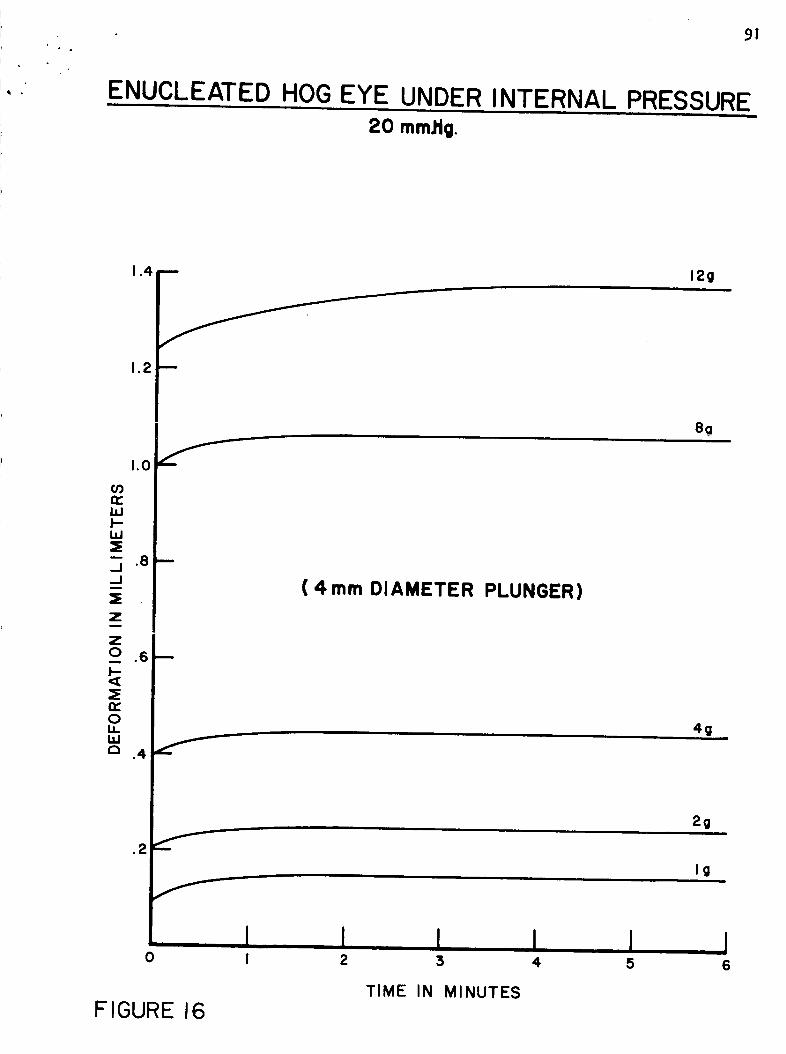
91
ENUCLEATED HOG EYE UNDER INTERNAL PRESSURE
20 mm.ttg.
1.4 -- 12g
1,2 m
1.0
CO
=E
.8 ---
z
.6 m
:EIZoLLLI.Ia .4 _
I0 I
81!_
( 4 mm DIAMETER PLUNGER)
4g
2g
Ig
I I I I2 3 4 5
TIME IN MINUTES
FIGURE 16
I6
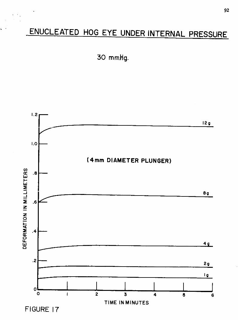
92
ENUCLEATED HOG EYE UNDER INTERNAL PRESSUREi
50 mmHg.
1"2 F
oo
1.0
.8
_E
Z= .6z
.4
.2
IJJr,t
f
I
O
FIGURE 17
(4ram DIAMETER PLUNGER)
1 I ,, !2 3 4
TIME IN MINUTES
I8
12g
8g
44
2g
Ig
6
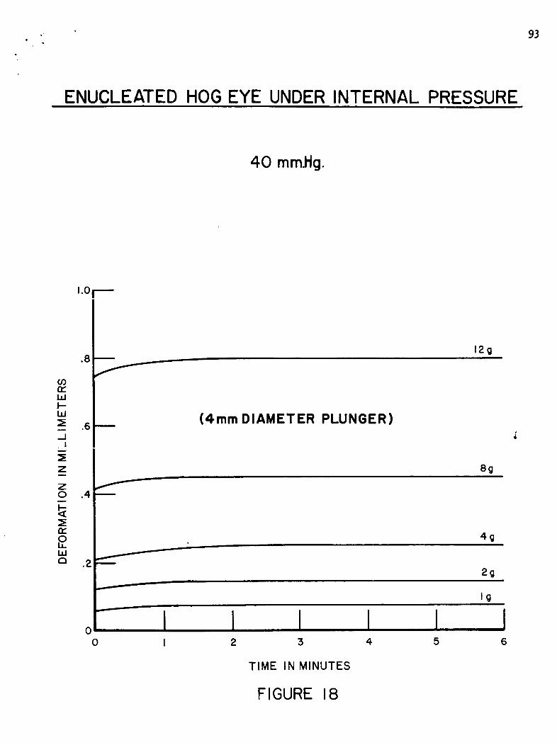
- 93
ENUCLEATED HOG EYE UNDER INTERNAL PRESSURE
40 mm.Hg.
1.0 r
.8 m
r,.Dnr"LIJI--LIJ
__ .6..J
I
_EZ
Z0 ,4
n.-0LLLIJr"t .2
f
D
00
(4ram DIAMETER PLUNGER)
12g
8g
4g
2g
Ig
I I I I I2 :5 4 5 6
TIME IN MINUTES
FIGURE 18
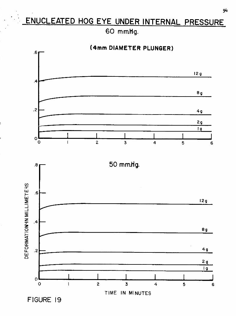
ENUCLEATED HOG EYE UNDER INTERNAL
94
PRESSURE60 mmHg.
.6 n
.2 m
f
0
(4ram DIAMETER PLUNGER)
12g
8g
4gi
2g
la
I I I I I II 2 3 4 5 6
ILl__ .6 !hi
-J f
z"11" .4 B
0
f¢Y0LL .2LLIa
00
FIGURE 19
i
II
50 mmHg.
12g
8g
4g
2g
Ig
TIME IN MINUTES
J I I I I2 :3 4 5 6
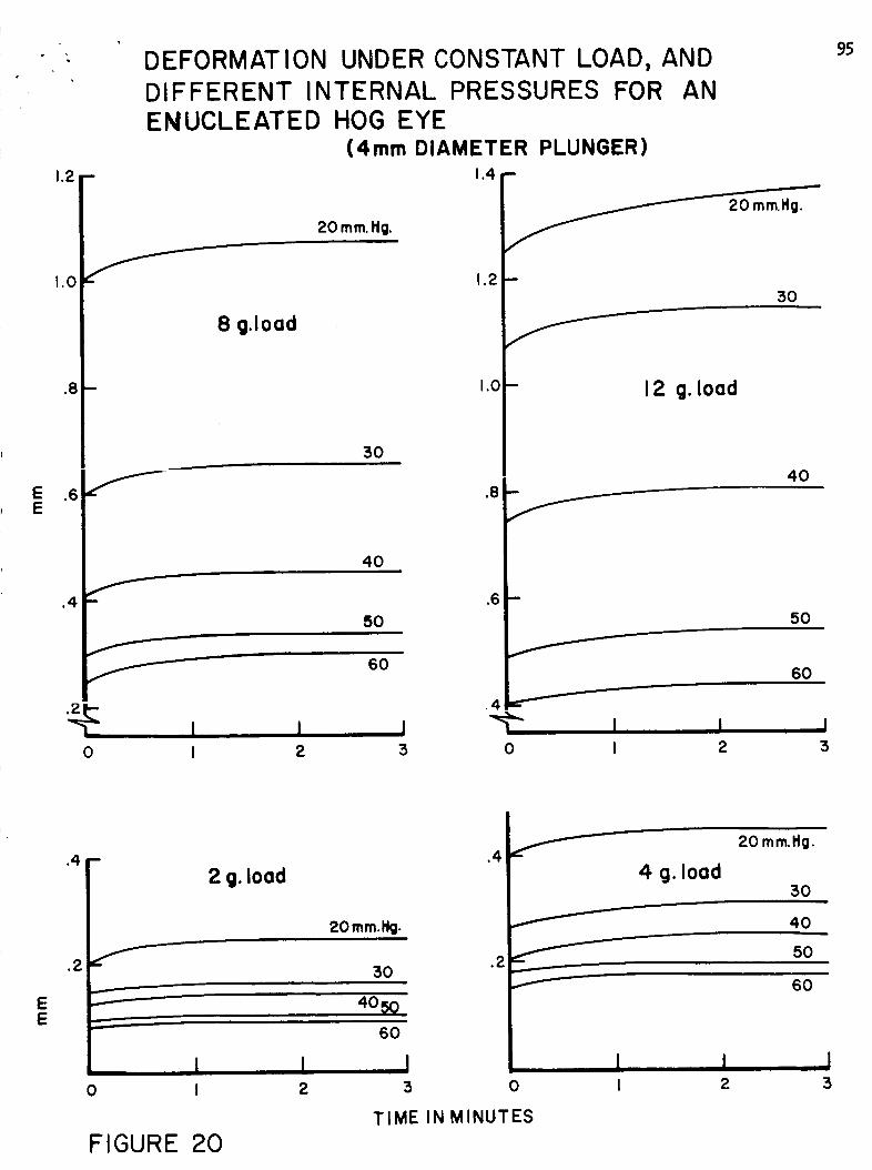
1.2
1.0
.8
.4
DEFORMATION UNDER CONSTANT LOAD, ANDDIFFERENT INTERNAL PRESSURES FOR ANENUCLEATED HOG EYE
(4mm DIAMETER PLUNGER)1.4 "
20mm.Ng.
1.2
8 g.lood
1.0
50
40
f-- .6
0
50
60
20 mm.Ng.
50
12 g. Iood
40
I I ! 1I 2 :5 0 I
I2
50
60
J5
95
EE
.4-
=.=.
,......=
===
0
FIGURE 20
2 g. Iood
20mmNg.
30
I2
60
I
3
.4
.2
4 g. lood
20 mm.Hg.
50
40
f 50
f 60
0
I I
I
I2
TIME IN MINUTES
J5
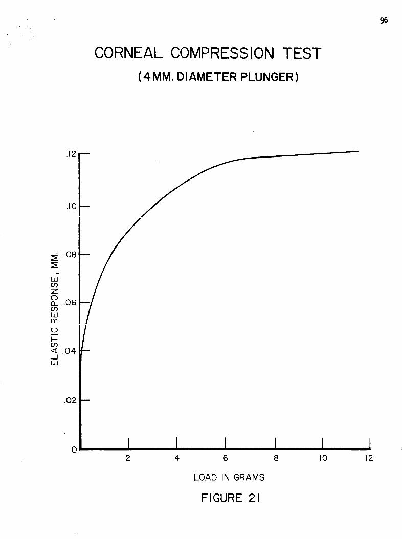
CORNEAL COMPRESSION TEST
(4 MM. DIAMETER PLUNGER )
96
.12 --
.10
.08
.06
#
I--09< .04_..1W
.O2
0
I
fm
I l I I l l2 4 6 8 I0 12
LOAD IN GRAMS
FIGURE 21
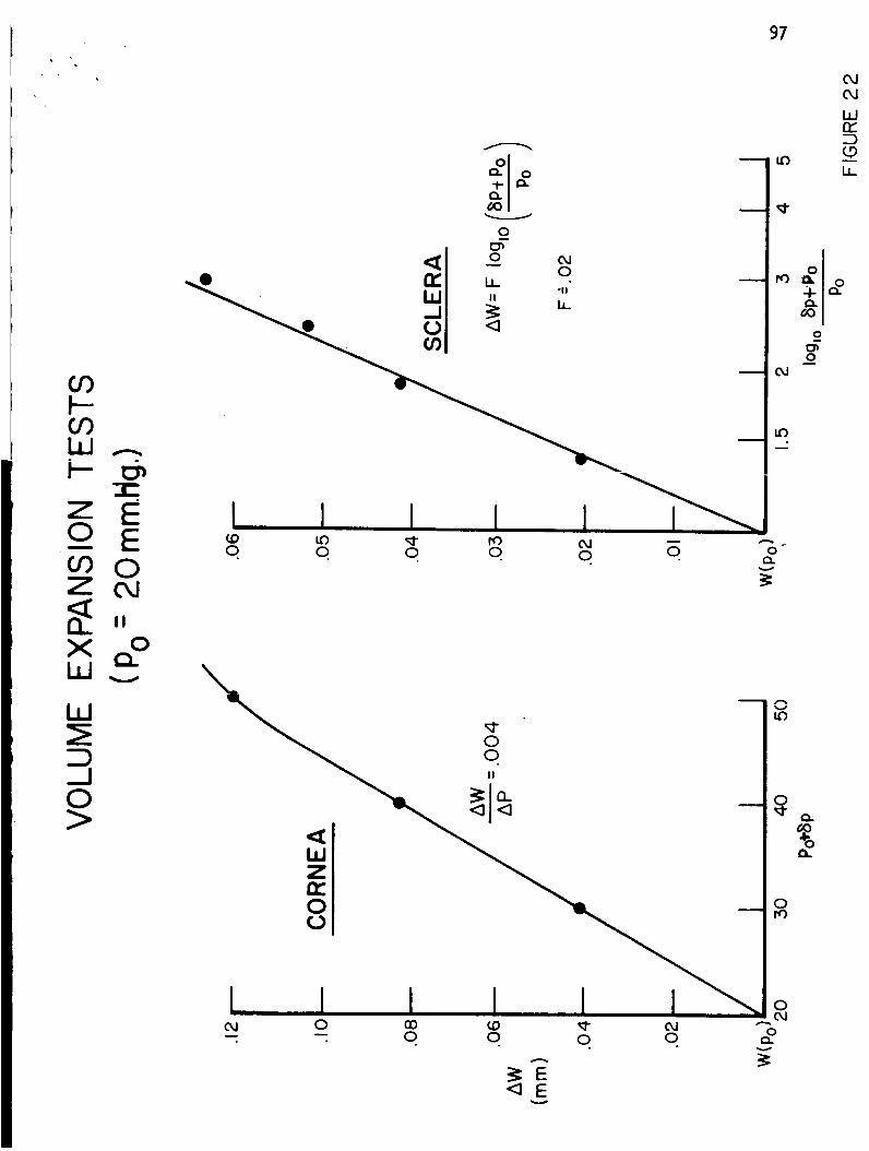
97
W
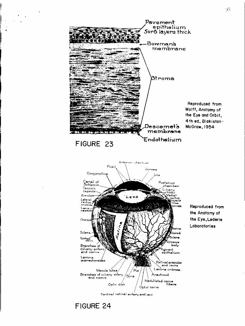
.... " .......... \Endotheliurn
F IGURE 23
Reproduced fromWolff, Anatomy ofthe Eye and Orbit,
4th ed, Blakiston-
McGraw, 1954
Cen_r, al _e_'inel _:e_'V mn_ vein
Reproduced from
the Anatomy of
the Eye,Lederle
Laboratories
FIGURE 24
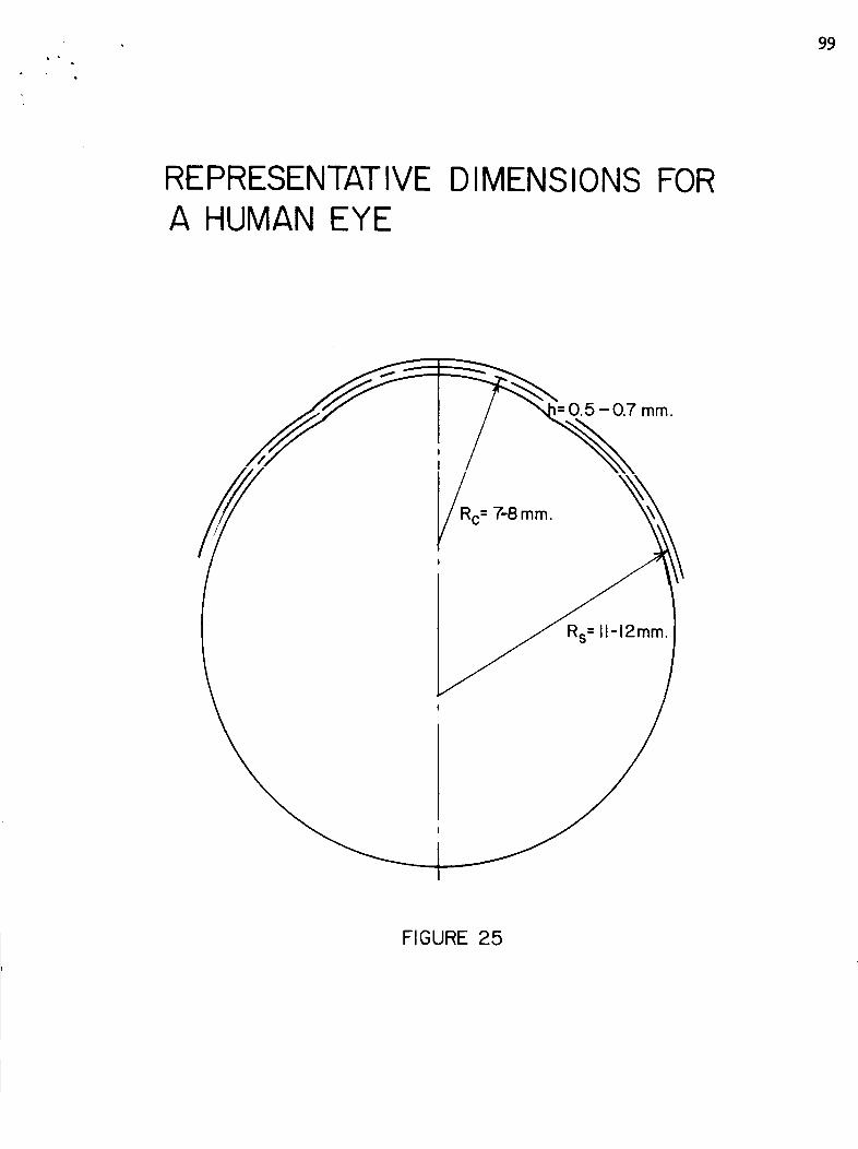
99
REPRESENTATIVE DIMENSIONS FORA HUMAN EYE
mm.
//
FIGURE 25
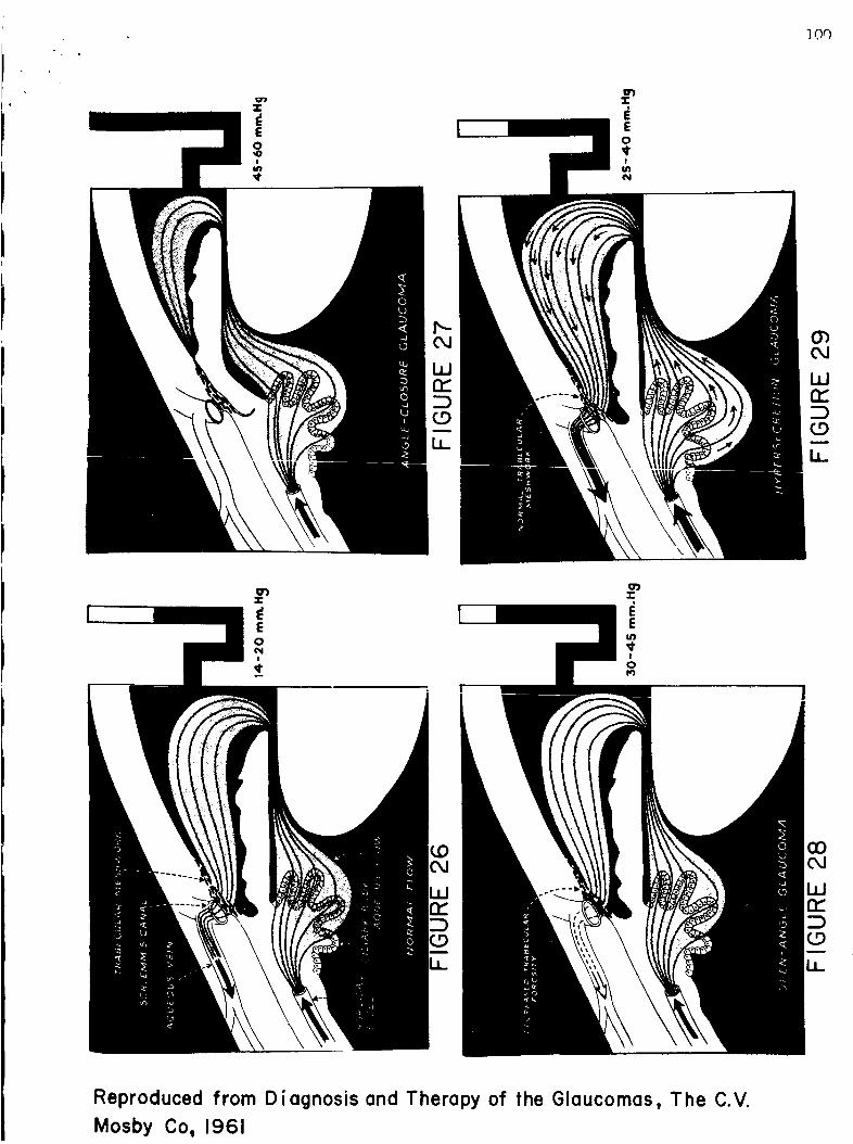
.l-
EO_o!
M7ql"
,T-
2
E0
¢I
_].Or)
,T
)
Z
E004i
,¢
Reproduced from Diagnosis and Therapy of the Glaucomas, The C.V.
Mosby Co, 1961
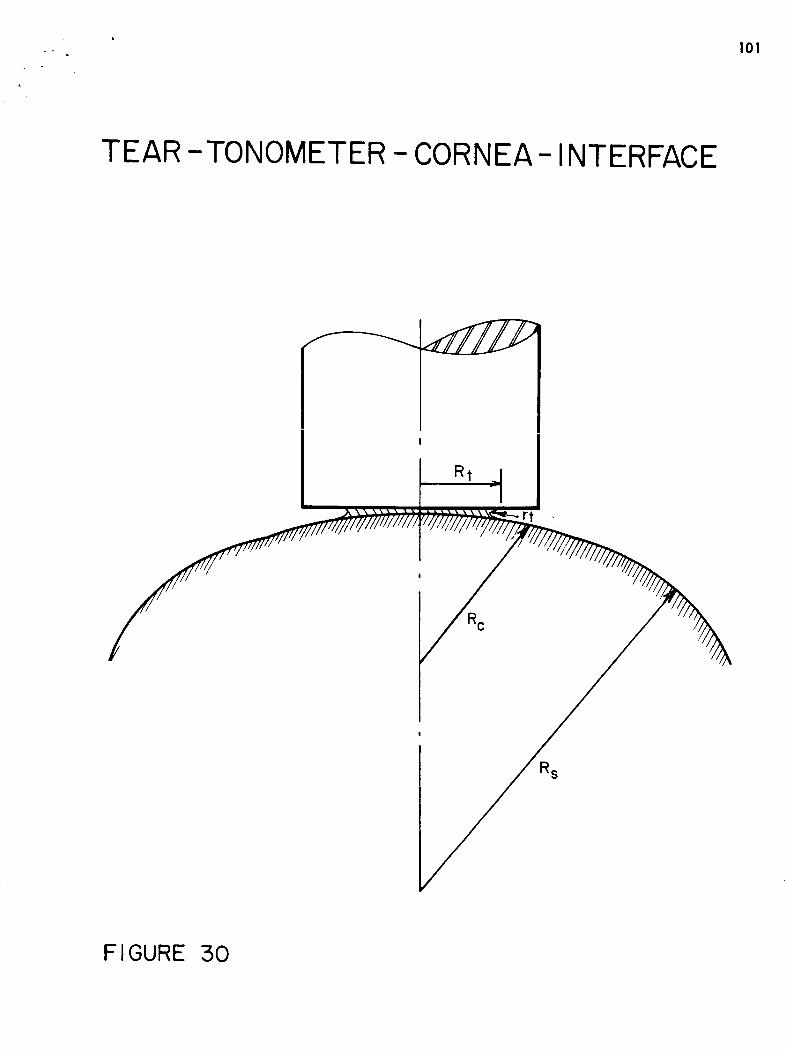
I01
TEAR -TONOMETER - CORNEA- INTERFACE
R C
R$
FIGURE 50
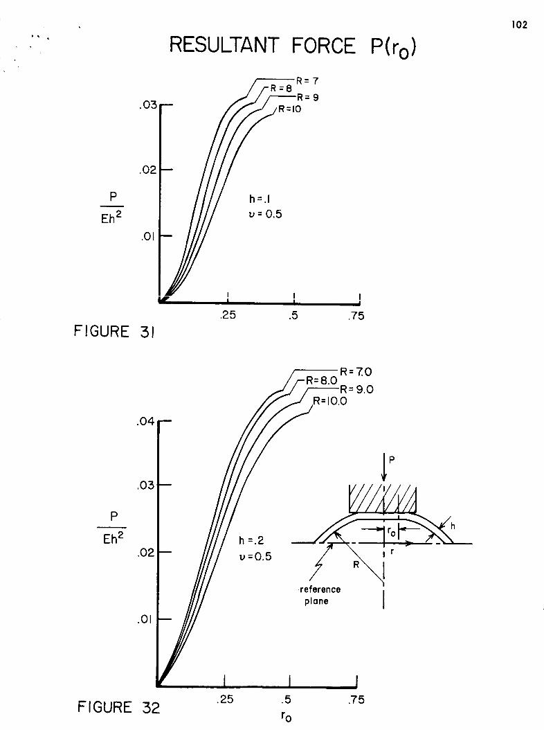
RESULTANT FORCE P(r o)
102
R=7=8
9R=IO
P
Eh 2
h=.l
u=0.5
FIGURE 31
I I II I I
.25 .5 .75
R=7.0
9.0
P
Eh 2 5=.2
u=0.5
P
referenceplane
FIGURE 32.25 .5
ro
.75
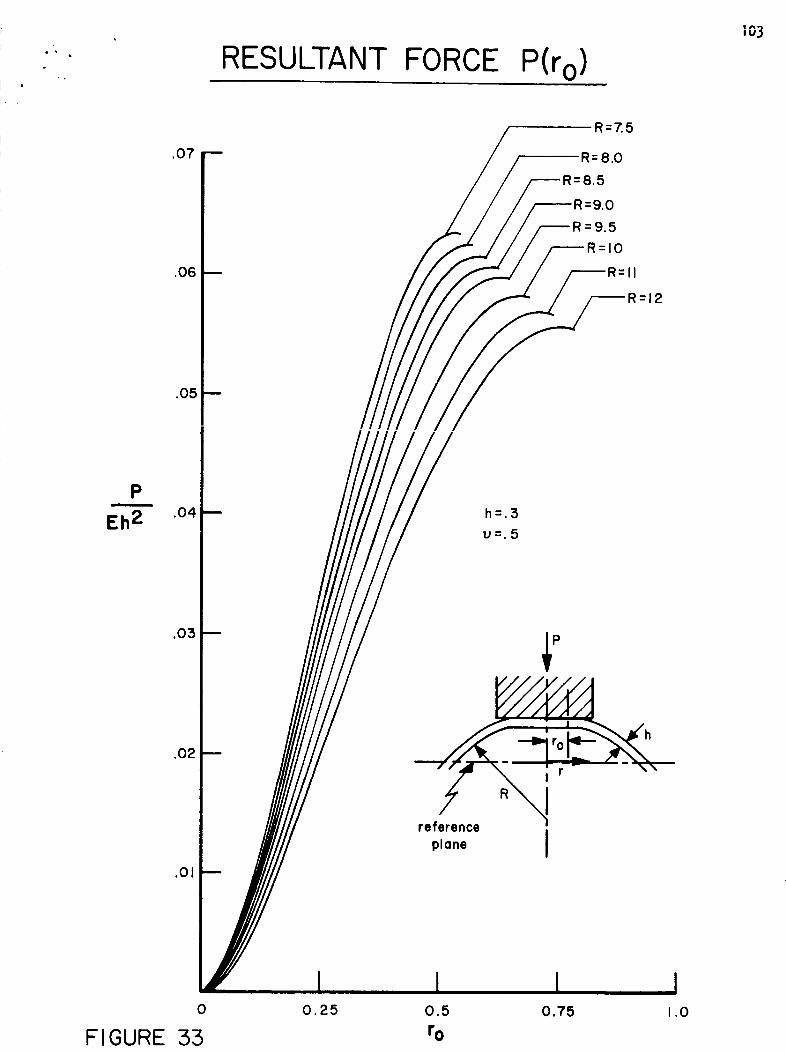
Q •
RESULTANT FORCE P(r o)Io3
.O7
.O6
.O5
R=7.5
R=8.0
5
_R=9.0
=9.5
R=IO
II
_R=I2
Eh 2 .o4h=.3
U=.5
plane J
0 0.25 0.5 0.75 1,0
FIGURE 55 ro
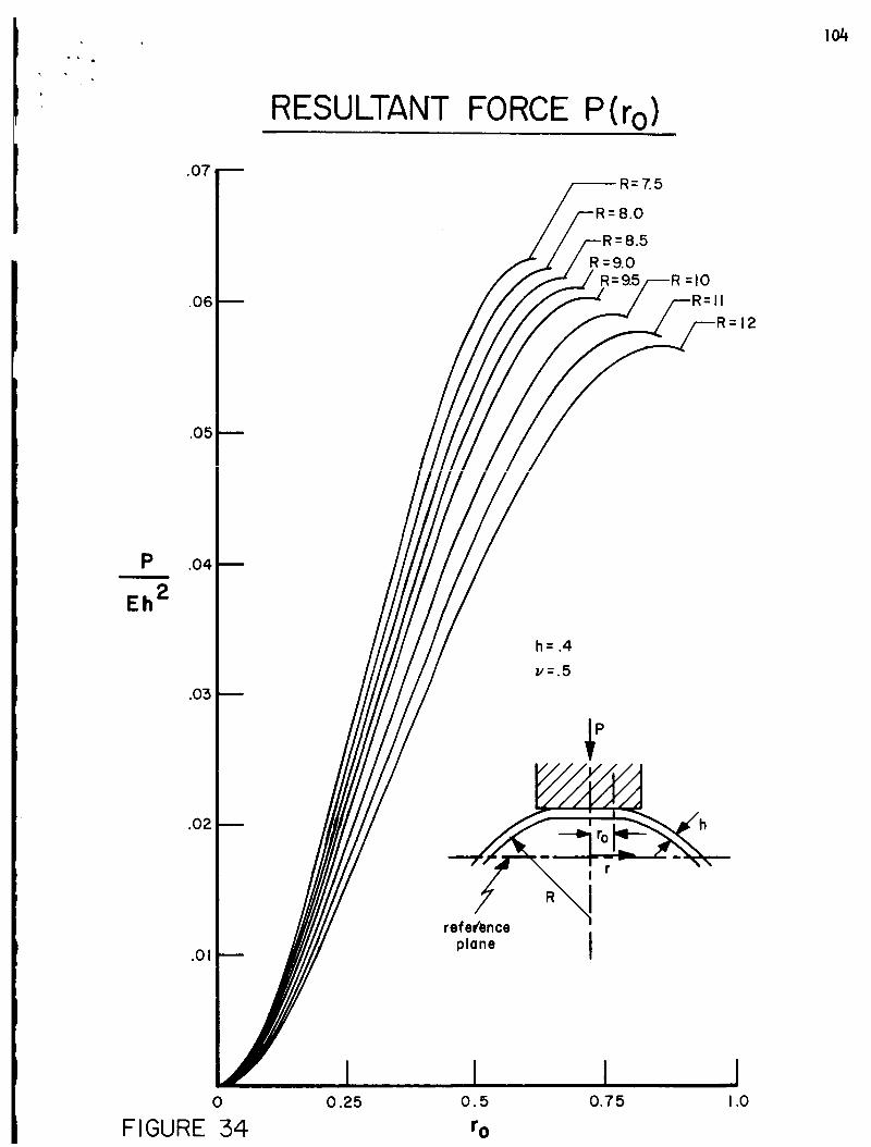
io4
RESULTANT FORCE P(ro)
Pm
Eh 2
.07
.06
.05
.04
.O5
.O2
.01
l/=.5
_refer,ence r°_
plane I
12
0
FIGURE 340.25 O. 5 0.75 1.0
r o
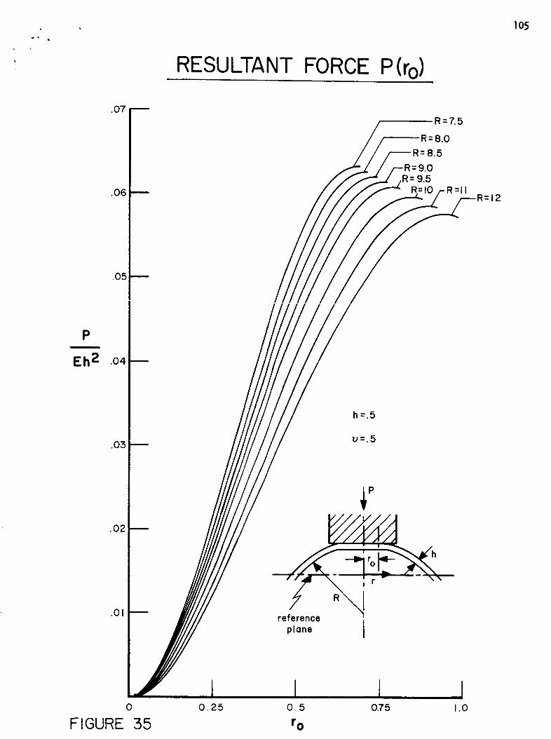
. IO5
RESULTANT FORCE P(ro)
.07
.06
.O5
Pm
Eh 2 .04
.03
.02
.01
/____R R R=7.5
R=8.0
=8.5=9.0
R= 9.5= =
R 12
h=.5
u=.5
0
FIGURE 550.25 0.5 0.75 1.0
r 0
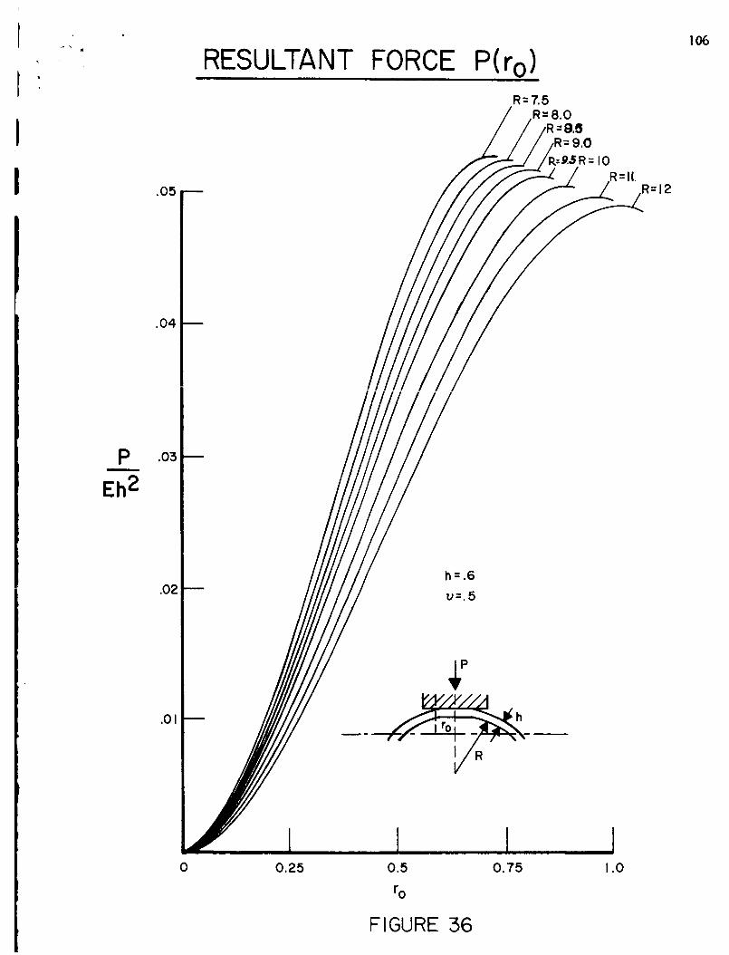
.05
RESULTANT FORCE P(r o)R=7.5
R=8.0
=.e.5R = I0R=II.
R=I2
106
P
Eh 2
.04
.03
.02
.01
h = .6
U=.5
I_Y/Y///I
0 0.25 0.5
ro
0.75 1.0
FIGURE 56
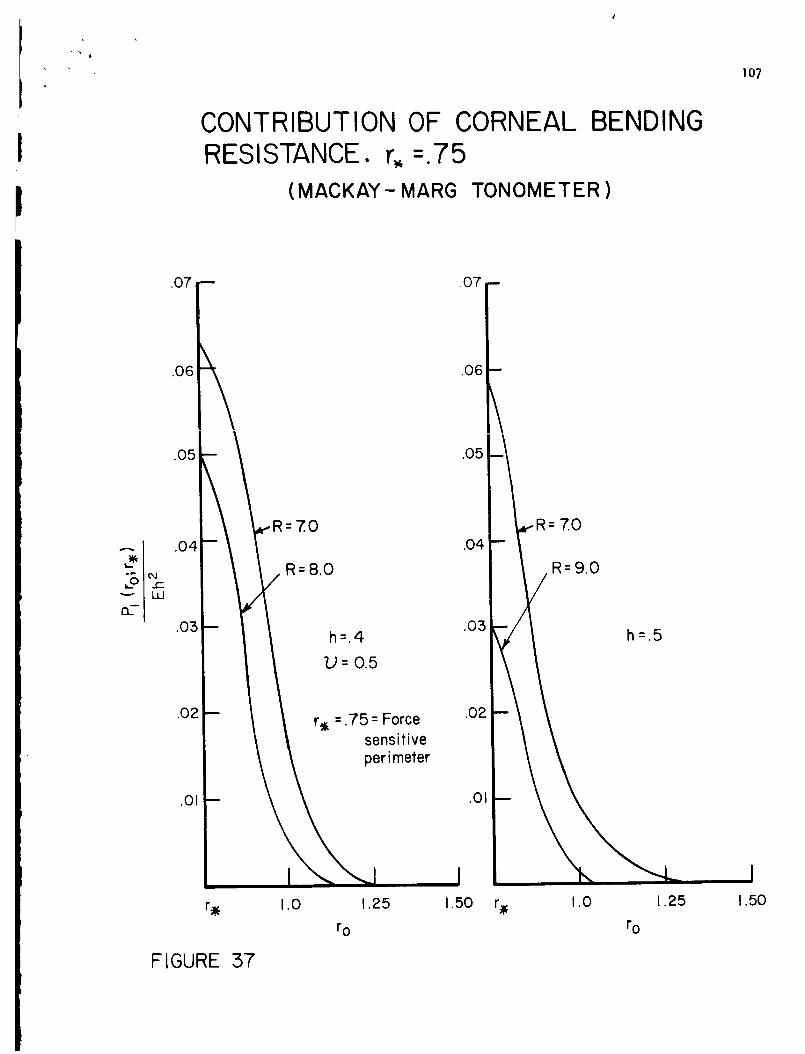
IO7
CONTRIBUTION OF CORNEAL
I RESISTANCE. r_ =.75BENDING
I (MACKAY- MARG TONOMETER )
.07 _ .07 --
.O6 .O6
.05 .05
R= 7..0
h=.4
U=0.5
R=8.0
.02 r_ = .75 = Force .02sensitive
perimeter
.01 .01
=70
R=9.0
h=.5
r_ 1.0 1.25 1.50
r o
r_ 1.0
r o
1.25 1.50
FIGURE 57
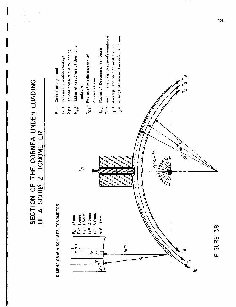
Io8
(.9ZI
a<
3n_ILll,iI
8°0
-r_N
_ -._ = .__ .- ._ _.
II
Q_
I.aJI--LU_E0Z0I-
NI--
"1"
if)
"6Z0
Z
IIt_ II II II II Vl
Recommended