MV2 SERIESTemperature Controller
Instruction Manual
www.incoe.com ©2014 INCOE® 11/14
MV2 SERIES CONTROLLERINSTRUCTION MANUAL
Page 1
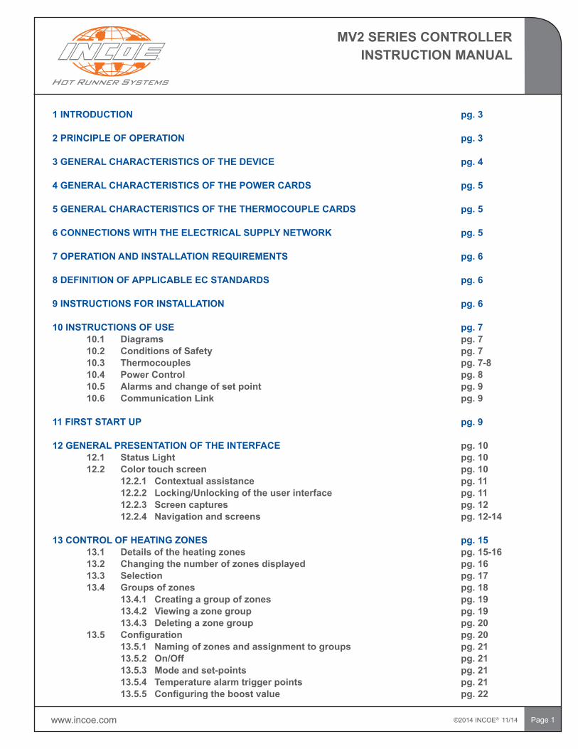
1 INTRODUCTION pg. 3 2 PRINCIPLE OF OPERATION pg. 3
3 GENERAL CHARACTERISTICS OF THE DEVICE pg. 4
4 GENERAL CHARACTERISTICS OF THE POWER CARDS pg. 5
5 GENERAL CHARACTERISTICS OF THE THERMOCOUPLE CARDS pg. 5
6 CONNECTIONS WITH THE ELECTRICAL SUPPLY NETWORK pg. 5
7 OPERATION AND INSTALLATION REQUIREMENTS pg. 6
8 DEFINITION OF APPLICABLE EC STANDARDS pg. 6
9 INSTRUCTIONS FOR INSTALLATION pg. 6
10 INSTRUCTIONS OF USE pg. 7 10.1 Diagrams pg. 7 10.2 Conditions of Safety pg. 7 10.3 Thermocouples pg. 7-8 10.4 Power Control pg. 8 10.5 Alarms and change of set point pg. 9 10.6 Communication Link pg. 9
11 FIRST START UP pg. 9
12 GENERAL PRESENTATION OF THE INTERFACE pg. 10 12.1 Status Light pg. 10 12.2 Color touch screen pg. 10 12.2.1 Contextual assistance pg. 11 12.2.2 Locking/Unlocking of the user interface pg. 11 12.2.3 Screen captures pg. 12 12.2.4 Navigation and screens pg. 12-14
13 CONTROL OF HEATING ZONES pg. 15 13.1 Details of the heating zones pg. 15-16 13.2 Changing the number of zones displayed pg. 16 13.3 Selection pg. 17 13.4 Groups of zones pg. 18 13.4.1 Creating a group of zones pg. 19 13.4.2 Viewing a zone group pg. 19 13.4.3 Deleting a zone group pg. 20 13.5 Configuration pg.20 13.5.1 Naming of zones and assignment to groups pg. 21 13.5.2 On/Off pg. 21 13.5.3 Mode and set-points pg. 21 13.5.4 Temperature alarm trigger points pg. 21 13.5.5 Configuringtheboostvalue pg.22
©2014 INCOE® 11/14 www.incoe.com
MV2 SERIES CONTROLLERINSTRUCTION MANUAL
Page 2
13.5.6 Power monitoring pg. 22-23 13.5.7 Back-up probe pg. 23 13.6 Quickconfigurationchanges pg.23 13.7 Raising/Lowering the set-point pg. 24 13.8 First and second set-points pg. 24 13.9 Electrical analysis of the mold pg. 25 13.9.1 Readings pg. 25-26 13.9.2 Comparing new and saved reading pg. 27 13.9.3 Results pg. 27 14 ALARM LOG pg. 28
15 GENERAL CONFIGURATION pg. 29 15.1 Temperature units pg. 29 15.2 Changeover to manual if a thermocouple fails pg. 29 15.3 Automatic current monitoring pg. 30 15.4 Boost duration pg. 30 15.5 Maximum and minimum set-points pg. 30 15.6 Alarm output pg. 30 15.7 Restore factory settings pg. 30
16 START UP RAMPS pg. 31
17 CONFIGURATION FILES pg. 32 17.1 Beforecreatingaconfigurationfile(commissioningamold) pg.32-33 17.2 Loadingaconfigurationfile pg.34 17.3 Updatingaconfigurationfile pg.34 17.4 Deletingaconfigurationfile pg.34 17.5 Copyingaconfigurationfile pg.34 17.6 ExportingandimportingconfigurationfileswithaUSBstick pg.35 17.6.1 Exportafile pg.35 17.6.2 Importafile pg.36
18 REGIONAL PARAMETERS pg. 37
19 MAINTENANCE INSTRUCTIONS pg. 38 19.1 Table of defects pg. 38-39 Procedure to be followed for injection controls pg. 40 Procedure to be followed by maintenance personnel pg. 40 19.2 Procedure to replace a power control card pg. 41 19.3 Procedure to replace a thermocouple card pg. 42 19.4 List of spare parts pg. 42
20 PARTIAL SUMMARY OF EXPRESS WARRANTY pg. 43
21 GLOBAL OFFICES AND SERVICE CONTACTS pg. 44
www.incoe.com ©2014 INCOE® 11/14
MV2 SERIES CONTROLLERINSTRUCTION MANUAL
Page 3
1 INTRODUCTION
A temperature controller to heat and maintain at temperature the hot runner system located in a mold.
2 PRINCIPLE OF OPERATION
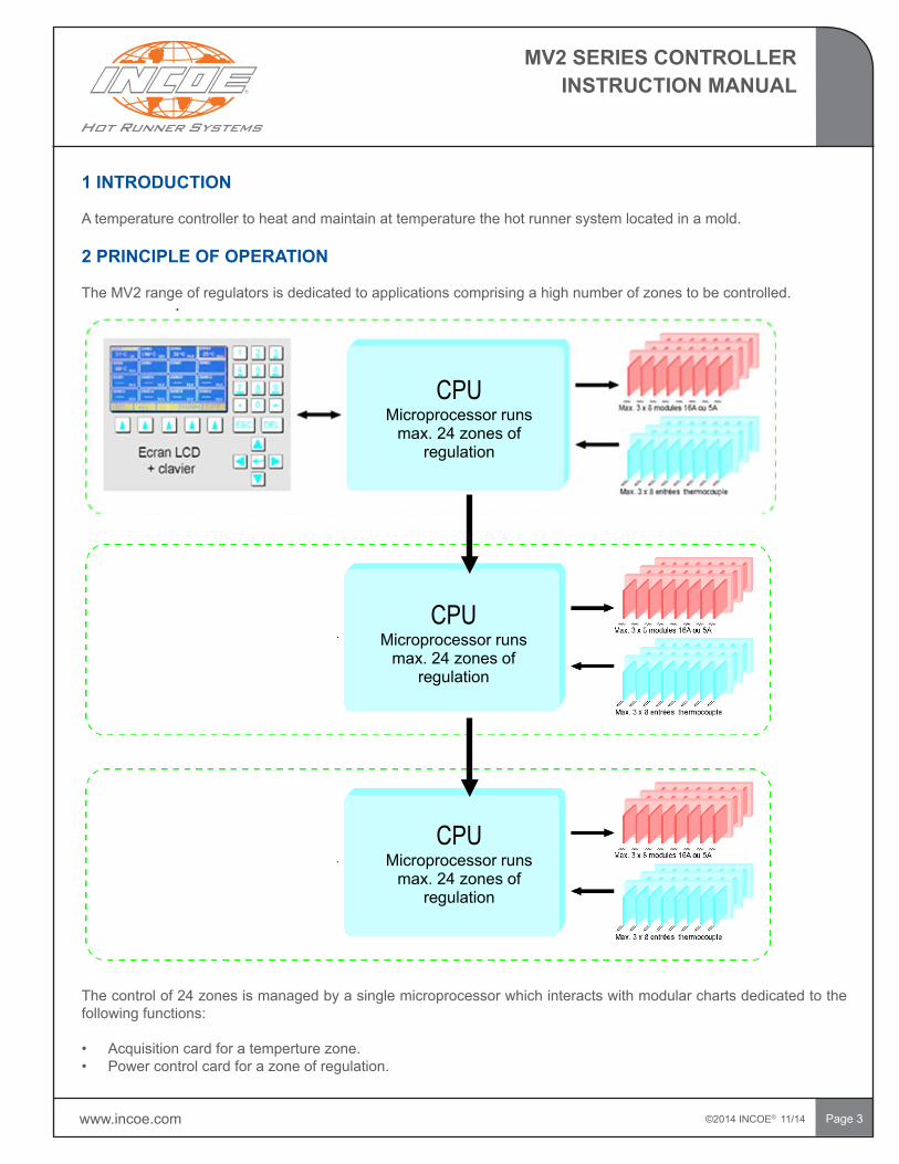
The MV2 range of regulators is dedicated to applications comprising a high number of zones to be controlled.
The control of 24 zones is managed by a single microprocessor which interacts with modular charts dedicated to the following functions:
• Acquisition card for a temperture zone.• Power control card for a zone of regulation.
.
CPUMicroprocessor runs
max. 24 zones of regulation
CPUMicroprocessor runs
max. 24 zones of regulation
CPUMicroprocessor runs
max. 24 zones of regulation
©2014 INCOE® 11/14 www.incoe.com
MV2 SERIES CONTROLLERINSTRUCTION MANUAL
Page 4
3 GENERAL CHARACTERISTICS OF THE DEVICE
ThecontrollersaresubjecttodirectiveEC73/23knownas″Lowvoltage″andrespectENstandard61010-1.Eachmachine is equipped with an electric feed cable dimensioned according to the maximum acceptable intensity.
NOTE: During operation, during the phase of rise in temperature of the regulators and according to the percentage of power used by each regulator, it may be that the intensity of the neutral is higher than the intensity on one of the three phases. This overcurrent is controlled by the principal circuit breaker located at the back of the box. Power consumption depends on the nominal power output of heated elements and the number of regulators used.
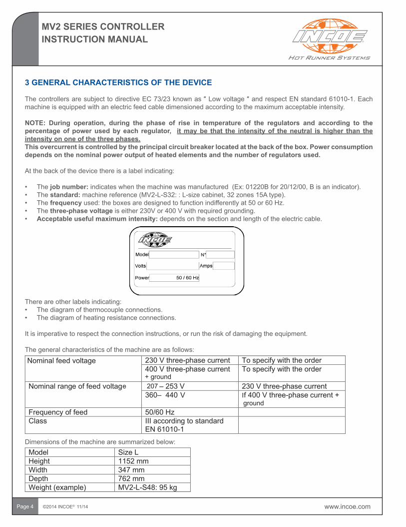
At the back of the device there is a label indicating:
• The job number:indicateswhenthemachinewasmanufactured(Ex:01220Bfor20/12/00,Bisanindicator).• The standard:machinereference(MV2-L-S32::L-sizecabinet,32zones15Atype).• The frequencyused:theboxesaredesignedtofunctionindifferentlyat50or60Hz.• The three-phase voltage iseither230Vor400Vwithrequiredgrounding.• Acceptable useful maximum intensity: depends on the section and length of the electric cable.
Dimensions of the machine are summarized below:Model SizeLHeight 1152mmWidth 347 mmDepth 762mmWeight(example) MV2-L-S48:95 kg
There are other labels indicating:• The diagram of thermocouple connections.• The diagram of heating resistance connections.
Itisimperativetorespecttheconnectioninstructions,orruntheriskofdamagingtheequipment.
The general characteristics of the machine are as follows:230Vthree-phase current To specify with the order400Vthree-phase current To specify with the order
Nominalrange of feed voltag – 253 V 230Vthree-phase current360– 440 f400V three-phase current +
Frequency of feed 50/60HzClass III according to standard
EN61010-1
Nominalfeedvoltage
ground
+ ground207e
V I
www.incoe.com ©2014 INCOE® 11/14
MV2 SERIES CONTROLLERINSTRUCTION MANUAL
Page5
4 GENERAL CHARACTERISTICS OF THE POWER CARDS
ThecontrollersaresubjecttoECdirective73/23knownas“Lowvoltage”andrespectENstandard61010-1.
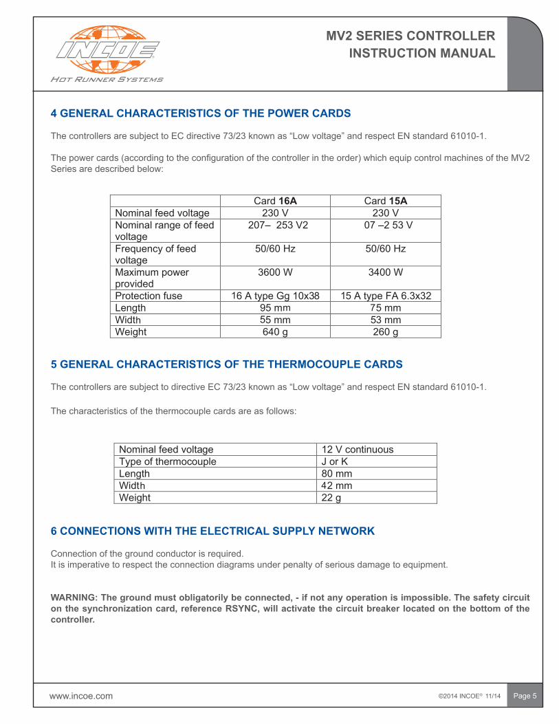
Thepowercards(accordingtotheconfigurationofthecontrollerintheorder)whichequipcontrolmachinesoftheMV2Seriesaredescribedbelow:
5 GENERAL CHARACTERISTICS OF THE THERMOCOUPLE CARDS
ThecontrollersaresubjecttodirectiveEC73/23knownas“Lowvoltage”andrespectENstandard61010-1.
The characteristics of the thermocouple cards are as follows:
6 CONNECTIONS WITH THE ELECTRICAL SUPPLY NETWORK
Connection of the ground conductor is required. It is imperative to respect the connection diagrams under penalty of serious damage to equipment.
WARNING: The ground must obligatorily be connected, - if not any operation is impossible. The safety circuit on the synchronization card, reference RSYNC, will activate the circuit breaker located on the bottom of the controller.
Card 16A Card 15ANominalfeed voltage 230V 230VNominalrange of feed voltage
207– 253 V2 07 –2 53 V
Frequency of feed voltage
50/60Hz 50/60Hz
Maximum power provided
3600 W 3400 W
Protection fus 6AtypeGg10x3 5AtypeFA 6.3x32Length 95m 5mmWidt 5mm 3 mmWeight 640g 260g
e 1 8 1
55h7m
Nominalfeed voltage 12 V continuousType of thermocouple J or KLength 80mmWidt 2 mmWeight 22 g
4h
©2014 INCOE® 11/14 www.incoe.com
MV2 SERIES CONTROLLERINSTRUCTION MANUAL
Page6
7 OPERATION AND INSTALLATION REQUIREMENTS
Installationinanindustrialandnon-wetenvironment.Rangeofoperatingtemperatures:from-10°Cto+60°C. Handling: while rolling the case. Unpacking: avoid shocks at all costs.
8 DEFINITION OF APPLICABLE EC STANDARDS
Genericemissionstandardforindustrialenvironment:EN50081-2Genericimmunitystandardforindustrialenvironment:EN50082-2
9 INSTRUCTIONS FOR INSTALLATION
IftheenvironmentandinstallationrequirementsdifferfromtheC.E.Mtestconditions,itisuptothefittertolayoutoneormorefilters,andpossibly,atransformerdevicebetweenthenetworkandthefeed,aswellastheessentialshieldingsand complementary protections required for the C.E.M.
www.incoe.com ©2014 INCOE® 11/14
MV2 SERIES CONTROLLERINSTRUCTION MANUAL
Page 7
10 INSTRUCTIONS OF USE
10.1 DIAGRAMS
The overall diagrams are in appendix.The electrical diagrams could be provided on request.
10.2 CONDITIONS OF SAFETY
The MV2 series controllers are equipped with:• A principal breaker for the protection of the tools. • An electronic circuit for monitoring voltage for the protection of the machines against ground defects and surges
(10%ofadditionalacceptablevoltage).• Ventilation,filterwithfrequencyofcleaningtobeplanned.
Each power card is protected by:• A surge protector(GEMOV)whichisusedasprotectionifthepowersupplyofthedeviceexceeds275V.• A HIGH-SPEED fuse on the phase and the ground whichprotects theTRIACagainst surges (16Aor 15A
maximumacceptable).
10.3 THERMOCOUPLES
Thebodiesoftemperaturemeasurementareconnectedviaspecifiedconnectorsfixedatthebackofthecontroller.ItcanbeaquestionoftypeJthermocouples(Iron-Constantan),orK(Ni.Cr/NiAL),orofauxiliaryentries.Forthermocouples,it is absolutely necessary to respect the poles indicated on the connection diagram.
Therearestandardswhichdefinethecolorofthermocouplewires,forexample:
Couple J(+=Fer,-=Constantan):• FrenchStandard: Iron:Yellow/Constantan:Black• GermanStandard: Iron:Red/Constantan:Blue• EnglishStandard: Iron:Yellow/Constantan:Blue• EuropeanStandard:Iron:Black/Constantan:White• AmericanStandard:Iron:White/Constantan:Red
The‘’+‘’isthewirewhichcanbeeasilyidentifiedthankstoamagnet.
K couples (+=ChromelorNickel-chromium,-=AlumelorNickel-aluminium)• FrenchStandard: Chromel:Yellow/Alumel:Blue• GermanStandard: Chromel:Red/Alumel:Green• EnglishStandard: Chromel:Red/Alumel:Blue• EuropeanStandard:Chromel:Green/Alumel:White• AmericanStandard:Chromel:Yellow/Alumel:Red
The connecting cables between thermocouples J or K and the plugs at the back of the controller must at all costs be of thesamemetalasthethermocouple(compensationcable)soasnottointroduceparasiticthermocouples.
©2014 INCOE® 11/14 www.incoe.com
MV2 SERIES CONTROLLERINSTRUCTION MANUAL
Page8
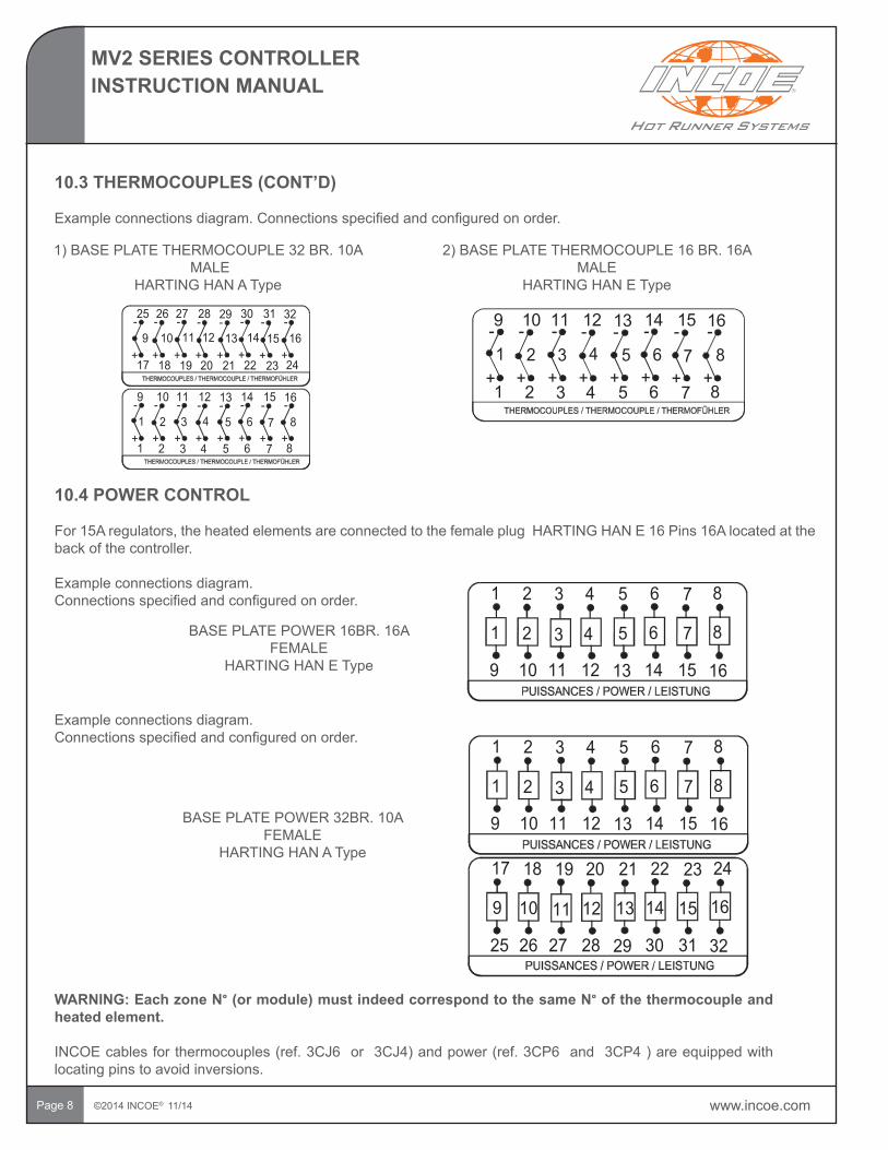
10.4 POWER CONTROL
For15Aregulators,theheatedelementsareconnectedtothefemaleplugHARTINGHANE16Pins16Alocatedattheback of the controller.
Example connections diagram. Connectionsspecifiedandconfiguredonorder.
1)BASEPLATETHERMOCOUPLE32BR.10AMALE
HARTINGHANAType
2)BASEPLATETHERMOCOUPLE16BR.16AMALE
HARTINGHANEType
BASEPLATEPOWER16BR.16AFEMALE
HARTINGHANEType
BASEPLATEPOWER32BR.10AFEMALE
HARTINGHANAType
WARNING: Each zone N°(ormodule)mustindeedcorrespondtothesameN° of the thermocouple and heated element.
INCOEcablesforthermocouples(ref.3CJ6or3CJ4)andpower(ref.3CP6and3CP4)areequippedwithlocating pins to avoid inversions.
Example connections diagram.Connectionsspecifiedandconfiguredonorder.
10.3THERMOCOUPLES(CONT’D)
Exampleconnectionsdiagram.Connectionsspecifiedandconfiguredonorder.
5 6 7 8
2 3 4 5 6 7 81
9 10 11 13 14 15 16
2 41 3
13 14 15 16
18 19 20 21 22 23 2417
25 26 27 28 29 30 31 32
10 129 11
12
18 19 20 21 22 23 2417
25 26 27 28 29 30 31 32- - --
+ + ++ + + + +
- - - -
2 3 4 5 6 7 81
9 10 11 12 13 14 15 16- - --
+ + ++ + + + +
- - - -87654321
11 12 13 14 15 16109
2 3 4 5 6 7 81
9 10 11 12 13 14 15 16- - --
+ + ++ + + + +
- - - -87654321
5 6 7 8
2 3 4 5 6 7 81
9 10 11 13 14 15 16
2 41 3
13 14 15 16
18 19 20 21 22 23 2417
25 26 27 28 29 30 31 32
10 129 11
12
www.incoe.com ©2014 INCOE® 11/14
MV2 SERIES CONTROLLERINSTRUCTION MANUAL
Page9
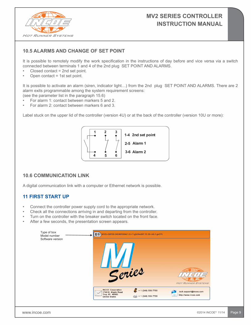
10.5 ALARMS AND CHANGE OF SET POINT
It ispossible to remotelymodify theworkspecification in the instructionsofdaybeforeandviceversaviaaswitchconnectedbetweenterminals1and4ofthe2ndplugSETPOINTANDALARMS.• Closed contact = 2nd set point. • Opencontact=1stsetpoint.
Itispossibletoactivateanalarm(siren,indicatorlight…)fromthe2ndplugSETPOINTANDALARMS.Thereare2alarm exits programmable among the system requirement screens: (seetheparameterlistintheparagraph15.6)• Foralarm1:contactbetweenmarkers5and2.• Foralarm2:contactbetweenmarkers6and3.
Labelstuckontheupperlidofthecontroller(version4U)oratthebackofthecontroller(version10Uormore):
10.6 COMMUNICATION LINK
A digital communication link with a computer or Ethernet network is possible.
11 FIRST START UP
• Connect the controller power supply cord to the appropriate network.• Check all the connections arriving in and departing from the controller.• Turn on the controller with the breaker switch located on the front face. • Afterafewseconds,thepresentationscreenappears.
Type of boxModel numberSoftware version
1-4
2-5
3-6 6
2nd set point
Alarm 1
Alarm 2
1 2 3
4 5
©2014 INCOE® 11/14 www.incoe.com
MV2 SERIES CONTROLLERINSTRUCTION MANUAL
Page10
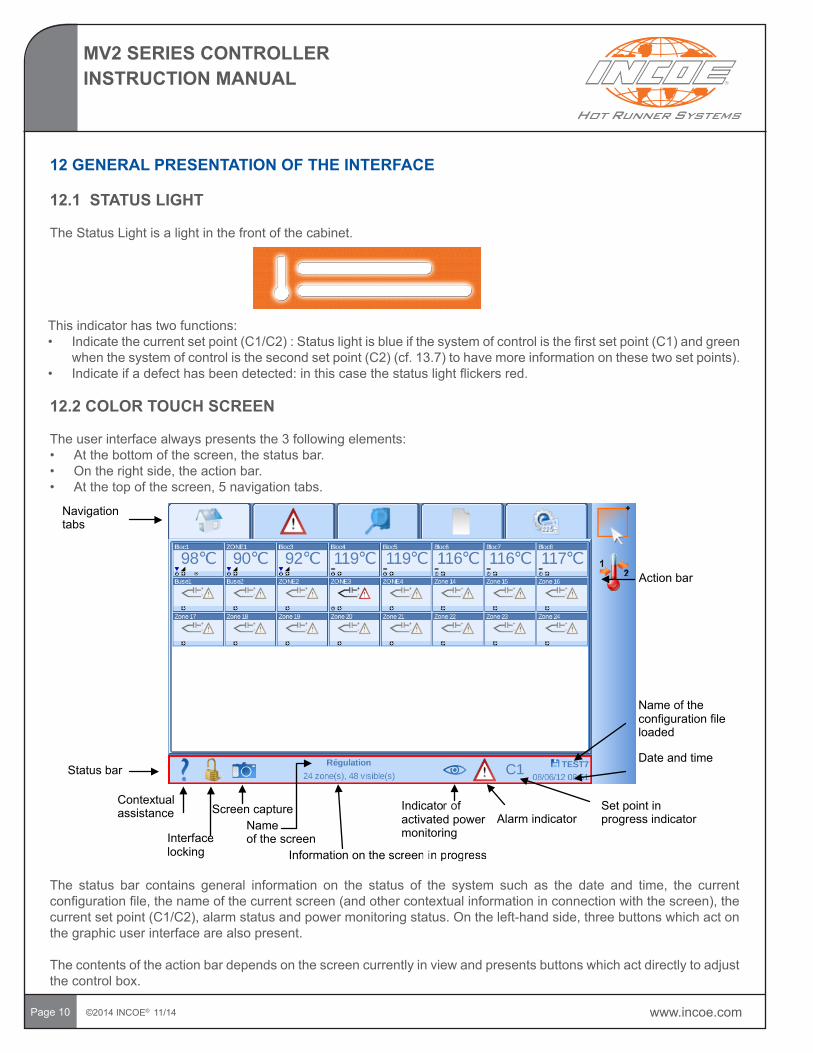
12 GENERAL PRESENTATION OF THE INTERFACE
12.1 STATUS LIGHT
TheStatusLightisalightinthefrontofthecabinet.
This indicator has two functions:• Indicatethecurrentsetpoint(C1/C2):Statuslightisblueifthesystemofcontrolisthefirstsetpoint(C1)andgreen
whenthesystemofcontrolisthesecondsetpoint(C2)(cf.13.7)tohavemoreinformationonthesetwosetpoints).• Indicateifadefecthasbeendetected:inthiscasethestatuslightflickersred.
12.2 COLOR TOUCH SCREEN
The user interface always presents the 3 following elements:• Atthebottomofthescreen,thestatusbar.• Ontherightside,theactionbar.• Atthetopofthescreen,5navigationtabs.
Navigation tabs
Statusbar
Action bar
Contextual assistance
Interface locking
e
Screencapture Name of the screen
Information on the screen in progressreen in progress
Indicato factivated power monitoring
Alarm indicatorSetpointinprogress indicator
Nameoftheconfiguration file loaded
Date and time
r o
The status bar contains general information on the status of the system such as the date and time, the currentconfigurationfile,thenameofthecurrentscreen(andothercontextualinformationinconnectionwiththescreen),thecurrentsetpoint(C1/C2),alarmstatusandpowermonitoringstatus.Ontheleft-handside,threebuttonswhichactonthe graphic user interface are also present.
The contents of the action bar depends on the screen currently in view and presents buttons which act directly to adjust the control box.
www.incoe.com ©2014 INCOE® 11/14
MV2 SERIES CONTROLLERINSTRUCTION MANUAL
Page 11
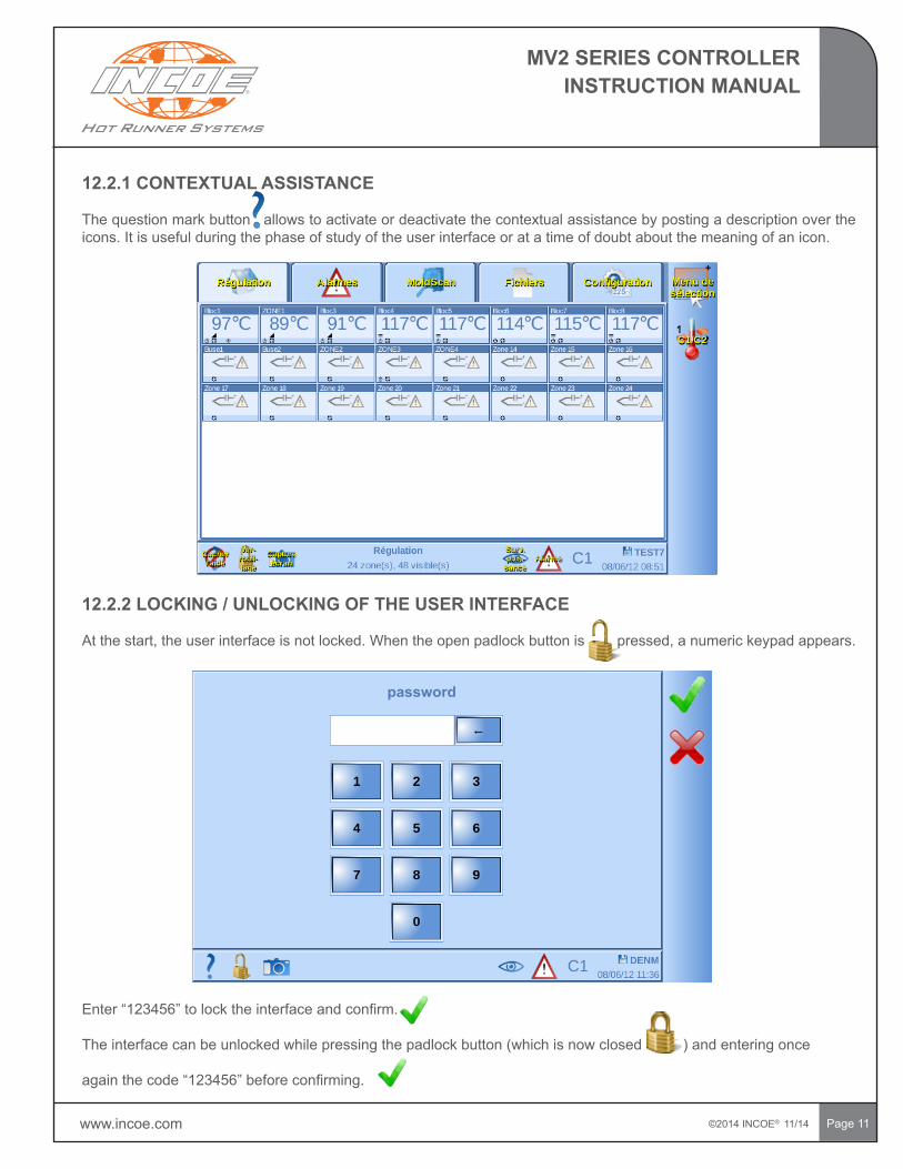
12.2.1 CONTEXTUAL ASSISTANCE
The question mark button allows to activate or deactivate the contextual assistance by posting a description over the icons. It is useful during the phase of study of the user interface or at a time of doubt about the meaning of an icon.
12.2.2 LOCKING / UNLOCKING OF THE USER INTERFACE
Atthestart,theuserinterfaceisnotlocked.Whentheopenpadlockbuttonispressed,anumerickeypadappears.
Enter“123456”tolocktheinterfaceandconfirm.
Theinterfacecanbeunlockedwhilepressingthepadlockbutton(whichisnowclosed)andenteringonce
againthecode“123456”beforeconfirming.
password
©2014 INCOE® 11/14 www.incoe.com
MV2 SERIES CONTROLLERINSTRUCTION MANUAL
Page 12
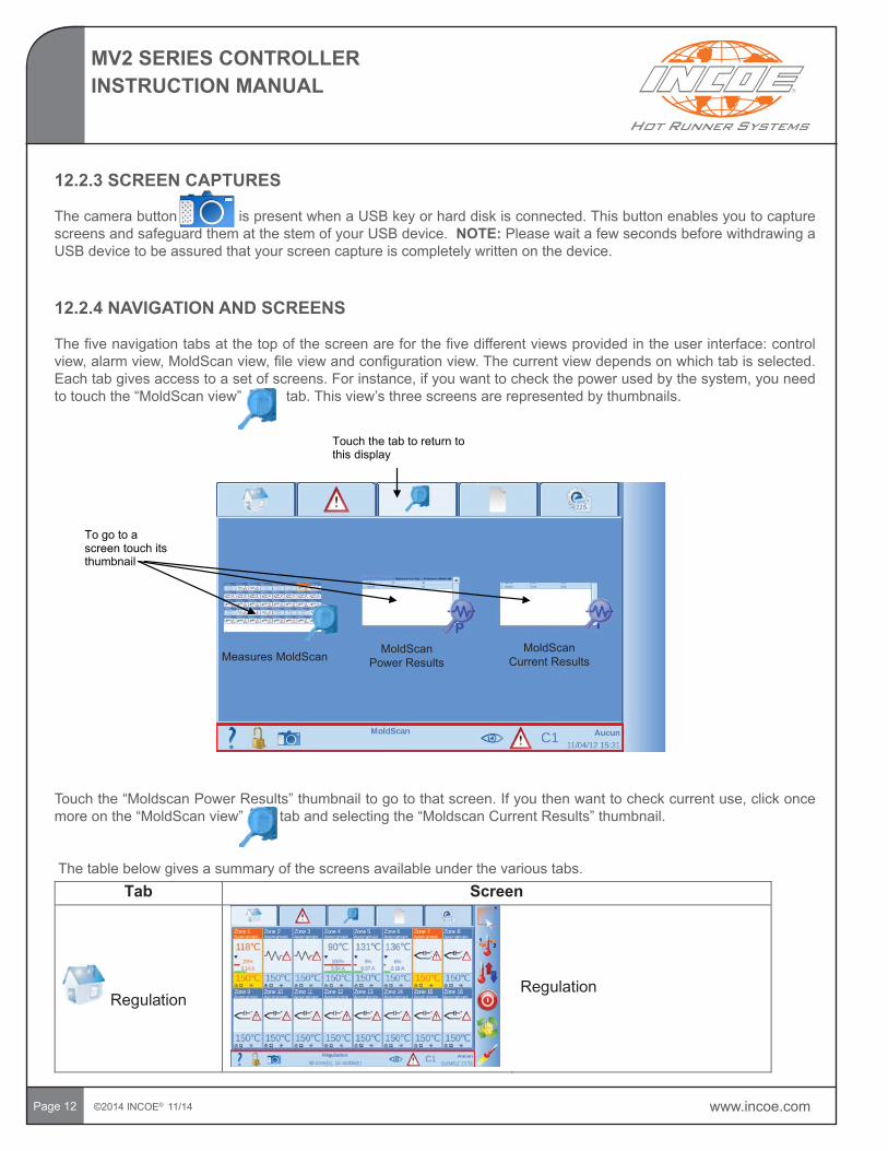
12.2.3 SCREEN CAPTURES
ThecamerabuttonispresentwhenaUSBkeyorharddiskisconnected.ThisbuttonenablesyoutocapturescreensandsafeguardthematthestemofyourUSBdevice.NOTE: Please wait a few seconds before withdrawing a USBdevicetobeassuredthatyourscreencaptureiscompletelywrittenonthedevice.
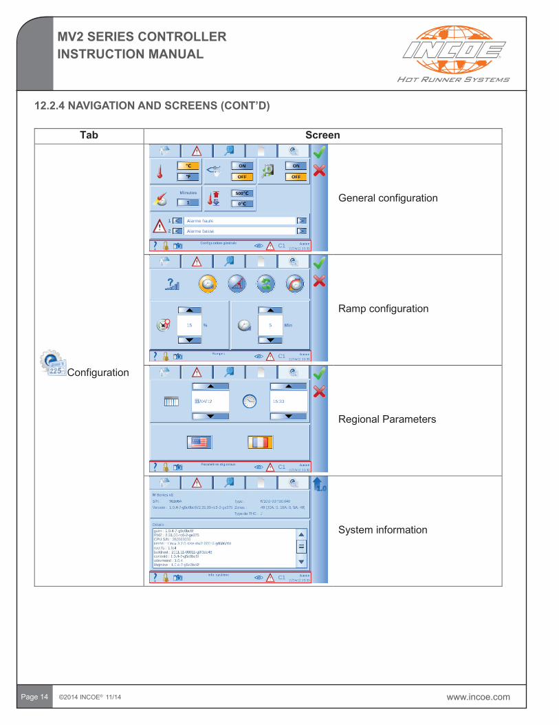
12.2.4 NAVIGATION AND SCREENS
Thefivenavigationtabsatthetopofthescreenareforthefivedifferentviewsprovidedintheuserinterface:controlview,alarmview,MoldScanview,fileviewandconfigurationview.Thecurrentviewdependsonwhichtabisselected.Eachtabgivesaccesstoasetofscreens.Forinstance,ifyouwanttocheckthepowerusedbythesystem,youneedtotouchthe“MoldScanview”tab.Thisview’sthreescreensarerepresentedbythumbnails.
To go to a screen touch its thumbnail
Touch the tab to return to this display
Touchthe“MoldscanPowerResults”thumbnailtogotothatscreen.Ifyouthenwanttocheckcurrentuse,clickoncemoreonthe“MoldScanview”tabandselectingthe“MoldscanCurrentResults”thumbnail.
The table below gives a summary of the screens available under the various tabs. Tab Screen
RegulationRegulation
MeasuresMoldScanMoldScan
Power ResultsMoldScan
Current Results
www.incoe.com ©2014 INCOE® 11/14
MV2 SERIES CONTROLLERINSTRUCTION MANUAL
Page 13
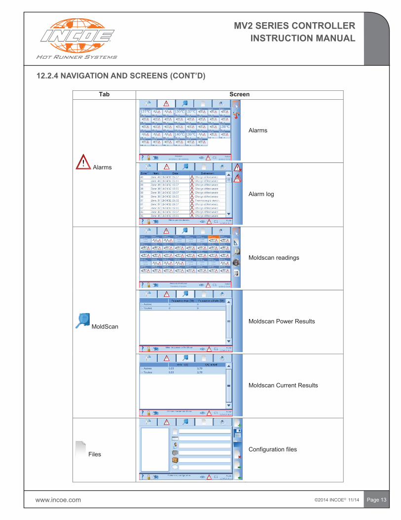
Tab Screen
Alarms
Alarms
Alarm log
MoldScan
Moldscan readings
Moldscan Power Results
Moldscan Current Results
FilesConfiguration files
12.2.4NAVIGATIONANDSCREENS(CONT’D)
©2014 INCOE® 11/14 www.incoe.com
MV2 SERIES CONTROLLERINSTRUCTION MANUAL
Page 14
Tab Screen
Configuration
General configuration
Ramp configuration
Regional Parameters
System information
12.2.4NAVIGATIONANDSCREENS(CONT’D)
www.incoe.com ©2014 INCOE® 11/14
MV2 SERIES CONTROLLERINSTRUCTION MANUAL
Page15
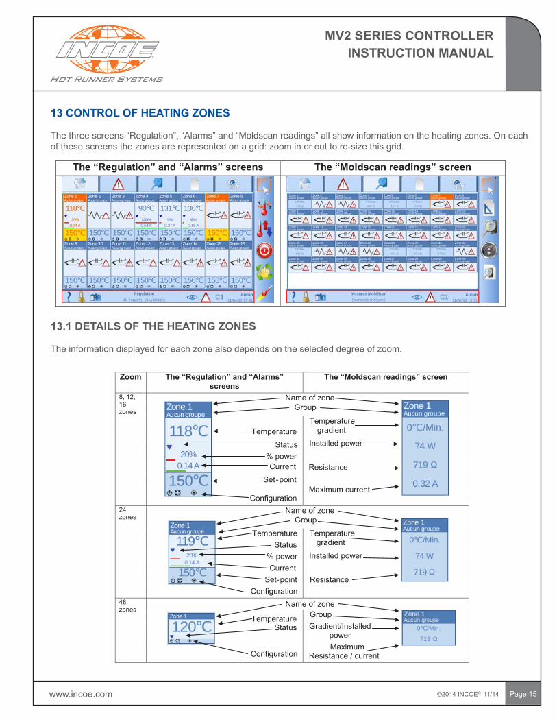
13 CONTROL OF HEATING ZONES
Thethreescreens“Regulation”,“Alarms”and“Moldscanreadings”allshowinformationontheheatingzones.Oneachofthesescreensthezonesarerepresentedonagrid:zoominorouttore-sizethisgrid.
The “Regulation” and “Alarms” screens The “Moldscan readings” screen
13.1 DETAILS OF THE HEATING ZONES
The information displayed for each zone also depends on the selected degree of zoom.
Zoom The “Regulation” and “Alarms” screens
The “Moldscan readings” screen
8, 12, 16zones
Name of zoneGroup
TemperatureTemperature
gradient
Status Installed power% powerCurrent Resistance
Set-pointMaximum current
Configuration24zones
Name of zoneGroup
Temperature Temperature gradientStatus
% power Installed powerCurrent
Set-point ResistanceConfiguration
48zones
Name of zone
Temperature GroupStatus Gradient/Installed
power
ConfigurationMaximum
Resistance / current
©2014 INCOE® 11/14 www.incoe.com
MV2 SERIES CONTROLLERINSTRUCTION MANUAL
Page16
13.1DETAILSOFTHEHEATINGZONES(CONT’D)
The meaning of the various status icons is described below:
,and:thetemperatureofthezoneiscorrect,thetemperatureisbelowtheset-point(LowTemperaturealarm)orthetemperatureisabovetheset-point(HighTemperaturealarm).
:ifthissymbolisdisplayed,arampisappliedtothezonetoraiseitstemperaturegraduallytoitsset-point.
Themeaningsoftheconfigurationiconsaregivenbelow::whenthisiconisdisplayedthezoneisOn,ifnotthezoneisOff. or : the zone is in automatic or in manual mode. :whenthisiconisdisplayedthezoneisinBoostmode.:whenthisiconisdisplayedpowermonitoringisactive(see13.5).:whenthisiconisdisplayedaback-upprobeisinplace(see13.5).
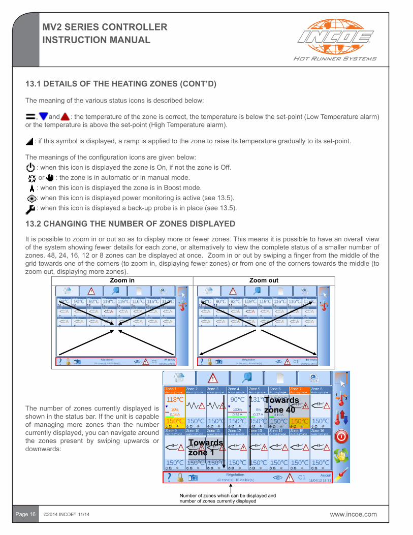
13.2 CHANGING THE NUMBER OF ZONES DISPLAYED
It is possible to zoom in or out so as to display more or fewer zones. This means it is possible to have an overall view ofthesystemshowingfewerdetailsforeachzone,oralternativelytoviewthecompletestatusofasmallernumberofzones.48,24,16,12or8zonescanbedisplayedatonce.Zoominoroutbyswipingafingerfromthemiddleofthegridtowardsoneofthecorners(tozoomin,displayingfewerzones)orfromoneofthecornerstowardsthemiddle(tozoomout,displayingmorezones).
Zoom in Zoom out
The number of zones currently displayed is shown in the status bar. If the unit is capable of managing more zones than the number currentlydisplayed,youcannavigatearoundthe zones present by swiping upwards or downwards:
Towards zone 1
Towards zone 40
Numberofzoneswhich can be displayed and number of zones currently displayed
www.incoe.com ©2014 INCOE® 11/14
MV2 SERIES CONTROLLERINSTRUCTION MANUAL
Page 17
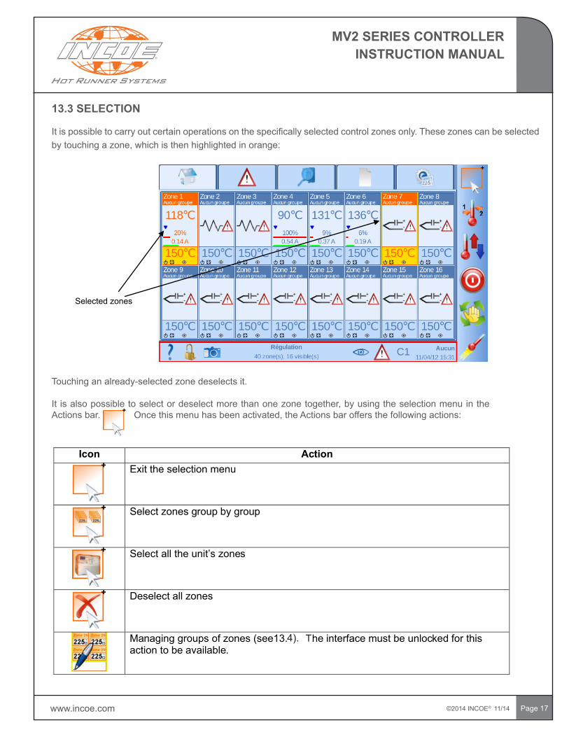
13.3 SELECTION
Itispossibletocarryoutcertainoperationsonthespecificallyselectedcontrolzonesonly.Thesezonescanbeselectedbytouchingazone,whichisthenhighlightedinorange:
Selectedzones
Touchinganalready-selectedzonedeselectsit.
It isalsopossibletoselectordeselectmorethanonezonetogether,byusingtheselectionmenuintheActionsbar.Oncethismenuhasbeenactivated,theActionsbaroffersthefollowingactions:
Icon ActionExit the selection menu
Selectzonesgroup by group
Selectalltheunit’szones
Deselect all zones
Managing groups of zones (see13. he interface must be unlocked for this action to be available.
4). T
©2014 INCOE® 11/14 www.incoe.com
MV2 SERIES CONTROLLERINSTRUCTION MANUAL
Page18
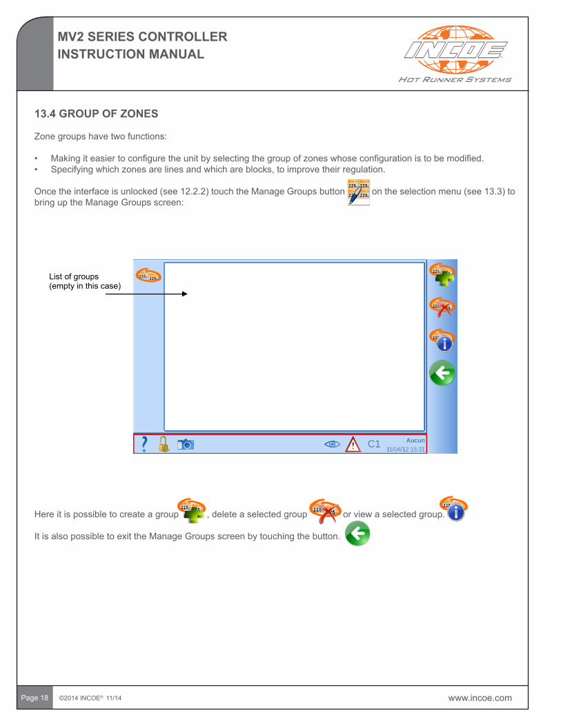
13.4 GROUP OF ZONES
Zonegroupshavetwofunctions:
• Makingiteasiertoconfiguretheunitbyselectingthegroupofzoneswhoseconfigurationistobemodified.• Specifyingwhichzonesarelinesandwhichareblocks,toimprovetheirregulation.
Oncetheinterfaceisunlocked(see12.2.2)touchtheManageGroupsbuttonontheselectionmenu(see13.3)tobringuptheManageGroupsscreen:
List of groups (emptyinthiscase)
Hereitispossibletocreateagroup,deleteaselectedgrouporviewaselectedgroup.
ItisalsopossibletoexittheManageGroupsscreenbytouchingthebutton.
www.incoe.com ©2014 INCOE® 11/14
MV2 SERIES CONTROLLERINSTRUCTION MANUAL
Page19
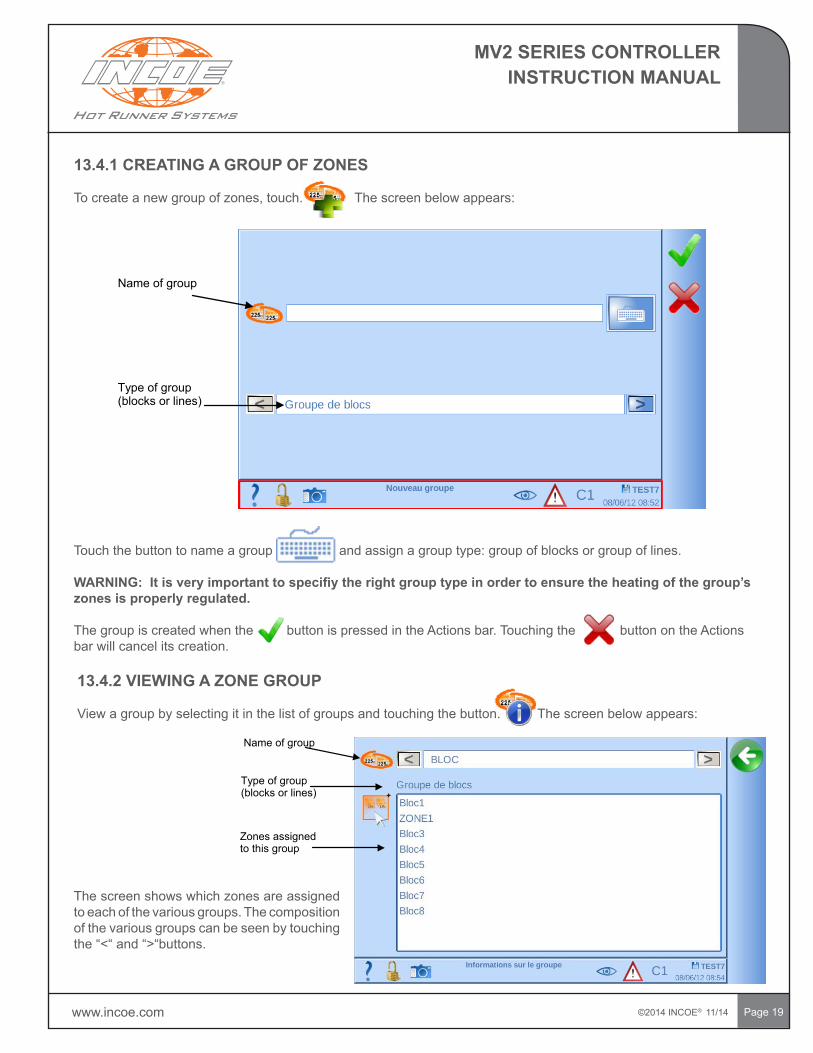
13.4.1 CREATING A GROUP OF ZONES
Tocreateanewgroupofzones,touch.Thescreenbelowappears:
Nameofgroup
Type of group (blocks or lines)
Touch the button to name a group and assign a group type: group of blocks or group of lines.
WARNING:Itisveryimportanttospecifiytherightgrouptypeinordertoensuretheheatingofthegroup’szones is properly regulated.
The group is created when the button is pressed in the Actions bar. Touching the button on the Actions bar will cancel its creation.
13.4.2 VIEWING A ZONE GROUP
View a group by selecting it in the list of groups and touching the button. The screen below appears:
Nameofgroup
Type of group (blocks or lines)
Zones assigned to this group
The screen shows which zones are assigned to each of the various groups. The composition of the various groups can be seen by touching the “<“ and “>“buttons.
©2014 INCOE® 11/14 www.incoe.com
MV2 SERIES CONTROLLERINSTRUCTION MANUAL
Page20
13.4.3 DELETING A ZONE GROUP
It is possible to delete a zone group by selecting it in the list of the groups and touching the button.
Youwillbeaskedtoconfirmthedeletion.ThegroupwillbedeletedifthebuttonispressedintheActionbar.Touching
the button on the Action bar will cancel the deletion of the group.
Onceagrouphasbeendeleted,itszonesnolongerbelongtoanygroup.
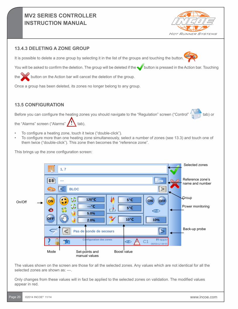
13.5 CONFIGURATION
Beforeyoucanconfiguretheheatingzonesyoushouldnavigatetothe“Regulation”screen(“Control”tab)or
the“Alarms”screen(“Alarms”tab).
• Toconfigureaheatingzone,touchittwice(“double-click”).• Toconfiguremorethanoneheatingzonesimultaneously,selectanumberofzones(see13.3)andtouchoneof
themtwice(“double-click”).Thiszonethenbecomesthe“referencezone”.
Thisbringsupthezoneconfigurationscreen:
On/Off
Mode Boostvalue
Powerm onitoring
Back-up probe
Selectedzones
Power monito
GroupGroup
Reference zone’s name and number
Set-pointsand manual values
The values shown on the screen are those for all the selected zones. Any values which are not identical for all the selectedzonesareshownas:---.
Onlychangesfromthesevalueswillinfactbeappliedtotheselectedzonesonvalidation.Themodifiedvaluesappear in red.
www.incoe.com ©2014 INCOE® 11/14
MV2 SERIES CONTROLLERINSTRUCTION MANUAL
Page 21
13.5.1 NAMING OF ZONES AND ASSIGNMENT TO GROUPS
Youcanchangethenameoftheselectedzone(s)bytouchingthebutton.Ifmorethanonezoneisselected,theselectionnumberisappendedtothenameentered.Forinstance,ifthezones2,5and7areselectedandthename“Block”isentered,thezoneswillbenamed“Block2”,“Block2”and“Block3”.
Zonescanbeassignedtoagroupbytouchingthe“<“and“>“buttons.
13.5.2 ON / OFF
Theselectedzonescanbeturnedonoroffbytouchingthe“ON”and“OFF”buttons.
.
13.5.3 MODE AND SET-POINTS
The heating zones can be regulated automatically or manually.
Inautomaticmodeaset-pointisspecifiedin°Corin°FandtheINCOEcontrolsystemautomaticallyselectsthepower to be applied to the zone in order to bring that zone up to the selected temperature and keep it there. Automatic modeneedsthezonetobefittedwithaworkingthermocoupleprobeor,failingthat,aback-upprobetohavebeenconfigured(cf.13.5.7).Underthismodethetemperatureismonitoredandalarmscanbeflashedup(see13.5.4).
Inmanualmodealevelofpowertobeappliedcanbespecifiedmanually.Thetemperatureisnotmonitoredatallinthis case.
TheINCOEcontrolsystemallowstheusertoconfiguretwotemperatureset-pointsforautomaticmode,andtwolevelsofpowertobeappliedinmanualmode.Thechoicebetweenthesetwoset-pointsorthesetwopowerlevelsismadeaccordingtotheset-pointmodechosenfortheunit(C1/C2).See13.7forfurtherdetails.
13.5.4 TEMERATURE ALARM TRIGGER POINTS
Zonetemperatureismonitoredinautomaticmode.Ifthistemperaturerisesaboveorfallsbelowtherelevantset-point,aHighorLowTemperaturealarmistriggered.Thealarmtriggerlevelscanbeconfiguredatthisscreen.Ifthesetriggerlevelsaresetat±5°Candthezone’sset-pointis150°C,aLowTemperaturealarmflashesupifthezone’smeasuredtemperaturefallsbelow145°C,andaHighTemperaturealarmifthetemperaturerisesabove155° C.
©2014 INCOE® 11/14 www.incoe.com
MV2 SERIES CONTROLLERINSTRUCTION MANUAL
Page 22
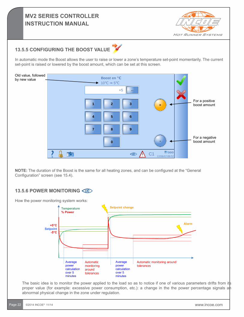
13.5.5 CONFIGURING THE BOOST VALUE
InautomaticmodetheBoostallowstheusertoraiseorlowerazone’stemperatureset-pointmomentarily.Thecurrentset-pointisraisedorloweredbytheboostamount,whichcanbesetatthisscreen.
Oldvalue,followed by new value
For a positive boost amount
For a negative boost amount
NOTE:ThedurationoftheBoostisthesameforallheatingzones,andcanbeconfiguredatthe“GeneralConfiguration”screen(see15.4).
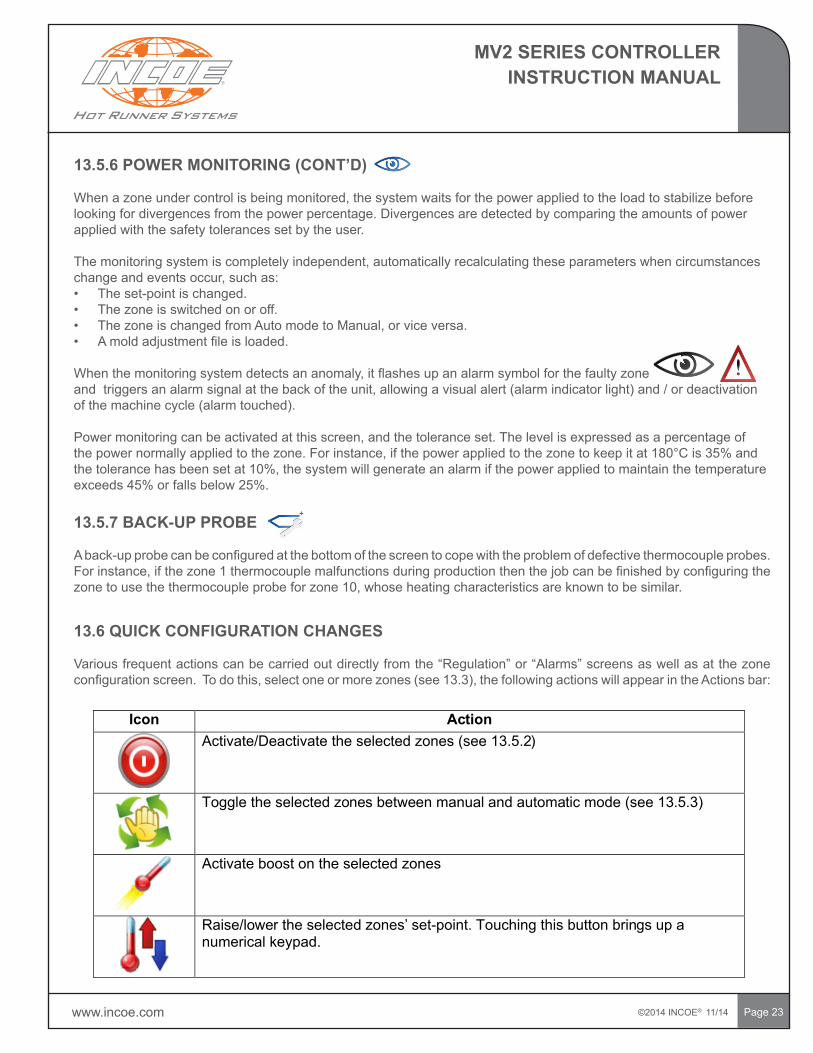
Temperature% Power
Alarm+5°C Setpoint
-5°C
Automatic monitoring around tolerances
Average power calculation over5 minutes
Automatic monitoring around tolerances
Average power calculation over5 minutes
Setpoint change
The basic idea is to monitor the power applied to the load so as to notice if one of various parameters drifts from its proper value (for example: excessive power consumption, etc.): a change in the the power percentage signals anabnormal physical change in the zone under regulation.
13.5.6 POWER MONITORING
Howthepowermonitoringsystemworks:
www.incoe.com ©2014 INCOE® 11/14
MV2 SERIES CONTROLLERINSTRUCTION MANUAL
Page 23
13.5.6POWERMONITORING(CONT’D)
Whenazoneundercontrolisbeingmonitored,thesystemwaitsforthepowerappliedtotheloadtostabilizebeforelooking for divergences from the power percentage. Divergences are detected by comparing the amounts of power applied with the safety tolerances set by the user.
Themonitoringsystemiscompletelyindependent,automaticallyrecalculatingtheseparameterswhencircumstanceschangeandeventsoccur,suchas:• Theset-pointischanged.• The zone is switched on or off.• ThezoneischangedfromAutomodetoManual,orviceversa.• Amoldadjustmentfileisloaded.
Whenthemonitoringsystemdetectsananomaly,itflashesupanalarmsymbolforthefaultyzoneandtriggersanalarmsignalatthebackoftheunit,allowingavisualalert(alarmindicatorlight)and/ordeactivationofthemachinecycle(alarmtouched).
Powermonitoringcanbeactivatedatthisscreen,andthetoleranceset.Thelevelisexpressedasapercentageofthepowernormallyappliedtothezone.Forinstance,ifthepowerappliedtothezonetokeepitat180°Cis35%andthetolerancehasbeensetat10%,thesystemwillgenerateanalarmifthepowerappliedtomaintainthetemperatureexceeds45%orfallsbelow25%.
13.5.7 BACK-UP PROBE
Aback-upprobecanbeconfiguredatthebottomofthescreentocopewiththeproblemofdefectivethermocoupleprobes.Forinstance,ifthezone1thermocouplemalfunctionsduringproductionthenthejobcanbefinishedbyconfiguringthezonetousethethermocoupleprobeforzone10,whoseheatingcharacteristicsareknowntobesimilar.
13.6 QUICK CONFIGURATION CHANGES
Variousfrequentactionscanbecarriedoutdirectlyfromthe“Regulation”or“Alarms”screensaswellasatthezoneconfigurationscreen.Todothis,selectoneormorezones(see13.3),thefollowingactionswillappearintheActionsbar:
Icon ActionActivate/Deactivatetheselectedzones(see13.5.2)
Toggle the selected zones between manual and automatic mode (see 13.5.3)
Activate boost on the selected zones
Raise/lower the selected zones’set-point.Touching this button brings up a numerical keypad.
©2014 INCOE® 11/14 www.incoe.com
MV2 SERIES CONTROLLERINSTRUCTION MANUAL
Page 24
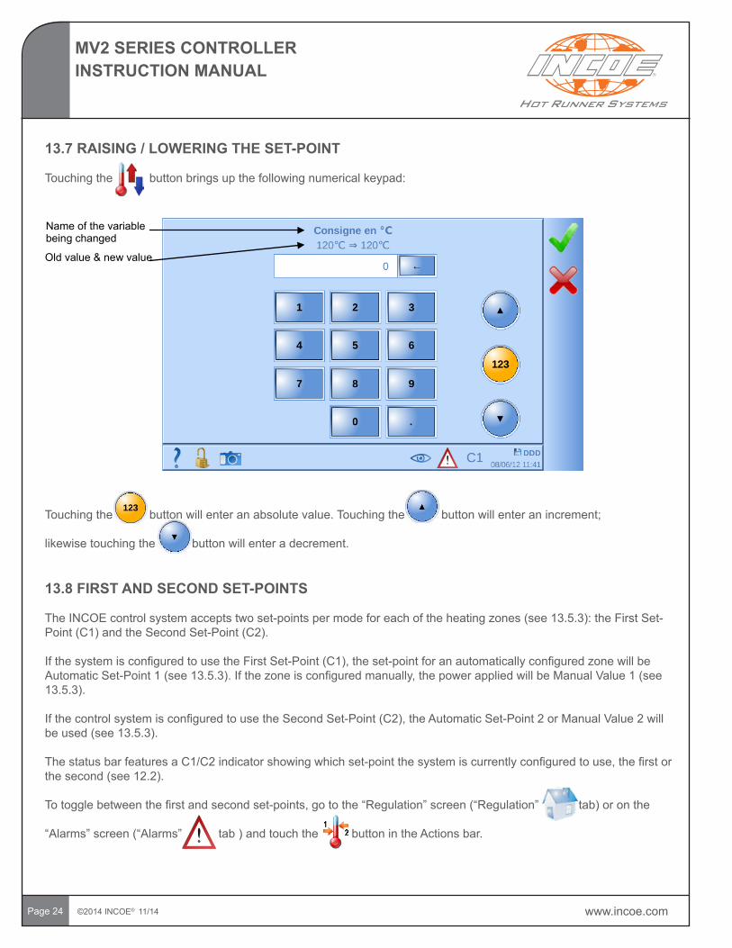
13.7 RAISING / LOWERING THE SET-POINT
Touching the button brings up the following numerical keypad:
Nameofthevariable being changed
Oldvalue&new value
Touching the button will enter an absolute value. Touching the button will enter an increment;
likewise touching the button will enter a decrement.
13.8 FIRST AND SECOND SET-POINTS
TheINCOEcontrolsystemacceptstwoset-pointspermodeforeachoftheheatingzones(see13.5.3):theFirstSet-Point(C1)andtheSecondSet-Point(C2).
IfthesystemisconfiguredtousetheFirstSet-Point(C1),theset-pointforanautomaticallyconfiguredzonewillbeAutomaticSet-Point1(see13.5.3).Ifthezoneisconfiguredmanually,thepowerappliedwillbeManualValue1(see13.5.3).
IfthecontrolsystemisconfiguredtousetheSecondSet-Point(C2),theAutomaticSet-Point2orManualValue2willbeused(see13.5.3).
ThestatusbarfeaturesaC1/C2indicatorshowingwhichset-pointthesystemiscurrentlyconfiguredtouse,thefirstorthesecond(see12.2).
Totogglebetweenthefirstandsecondset-points,gotothe“Regulation”screen(“Regulation”tab)oronthe
“Alarms”screen(“Alarms”tab)andtouchthebuttonintheActionsbar.
www.incoe.com ©2014 INCOE® 11/14
MV2 SERIES CONTROLLERINSTRUCTION MANUAL
Page25
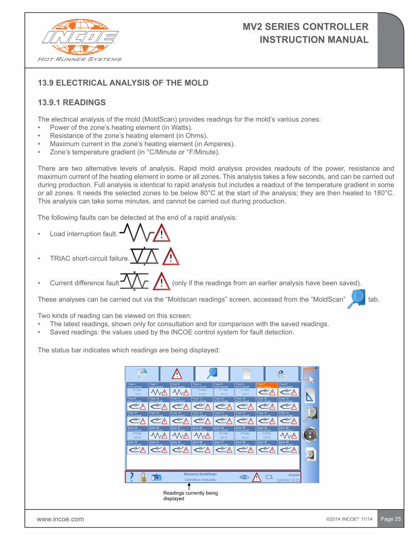
Readings currently being displayed
13.9 ELECTRICAL ANALYSIS OF THE MOLD
13.9.1 READINGS
Theelectricalanalysisofthemold(MoldScan)providesreadingsforthemold’svariouszones:• Powerofthezone’sheatingelement(inWatts).• Resistanceofthezone’sheatingelement(inOhms).• Maximumcurrentinthezone’sheatingelement(inAmperes).• Zone’stemperaturegradient(in°C/Minuteor°F/Minute).
There are two alternative levels of analysis. Rapid mold analysis provides readouts of the power, resistance andmaximumcurrentoftheheatingelementinsomeorallzones.Thisanalysistakesafewseconds,andcanbecarriedoutduring production. Full analysis is identical to rapid analysis but includes a readout of the temperature gradient in some orallzones.Itneedstheselectedzonestobebelow80°Catthestartoftheanalysis;theyarethenheatedto180°C.Thisanalysiscantakesomeminutes,andcannotbecarriedoutduringproduction.
The following faults can be detected at the end of a rapid analysis:
• Loadinterruptionfault.
• TRIACshort-circuitfailure.
• Currentdifferencefault(onlyifthereadingsfromanearlieranalysishavebeensaved).
Theseanalysescanbecarriedoutviathe“Moldscanreadings”screen,accessedfromthe“MoldScan”tab.
Two kinds of reading can be viewed on this screen:• Thelatestreadings,shownonlyforconsultationandforcomparisonwiththesavedreadings.• Savedreadings:thevaluesusedbytheINCOEcontrolsystemforfaultdetection.
The status bar indicates which readings are being displayed:
©2014 INCOE® 11/14 www.incoe.com
MV2 SERIES CONTROLLERINSTRUCTION MANUAL
Page26
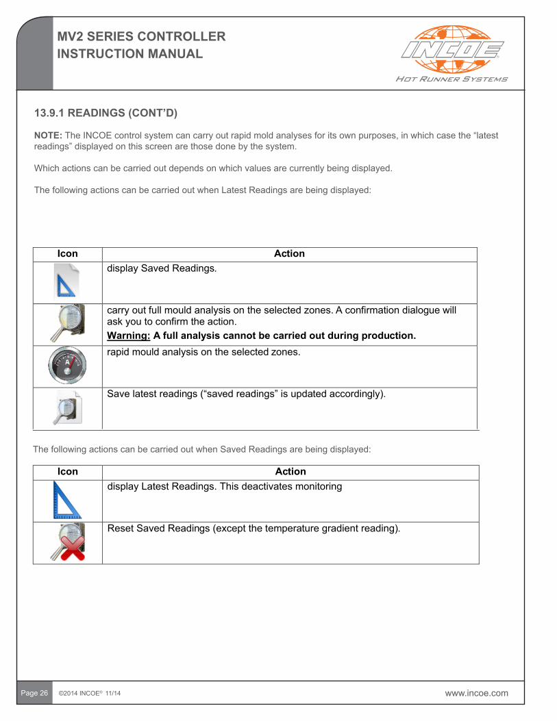
13.9.1READINGS(CONT’D)
NOTE:TheINCOEcontrolsystemcancarryoutrapidmoldanalysesforitsownpurposes,inwhichcasethe“latestreadings”displayedonthisscreenarethosedonebythesystem.
Which actions can be carried out depends on which values are currently being displayed.
ThefollowingactionscanbecarriedoutwhenLatestReadingsarebeingdisplayed:
Icon ActiondisplaySavedReadings.
carry out full mould analysis on the selected zones. A confirmation dialogue will ask you to confirm the action.Warning: A full analysis cannot be carried out during production.rapid mould analysis on the selected zones.
Savelatestreadings (“savedreadings”isupdated accordingly).
Icon ActiondisplayLatestReadings.Thisdeactivatesmonitoring
Reset SavedReadings (except the temperaturegradientreading).
ThefollowingactionscanbecarriedoutwhenSavedReadingsarebeingdisplayed:
www.incoe.com ©2014 INCOE® 11/14
MV2 SERIES CONTROLLERINSTRUCTION MANUAL
Page 27
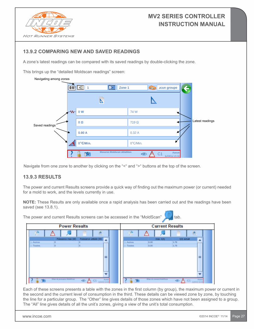
13.9.2 COMPARING NEW AND SAVED READINGS
Azone’slatestreadingscanbecomparedwithitssavedreadingsbydouble-clickingthezone.
Thisbringsupthe“detailedMoldscanreadings”screen:
SavedreadingsLatest readings
Navigatingamongzones
Navigatefromonezonetoanotherbyclickingonthe“<“and“>“buttonsatthetopofthescreen.
13.9.3 RESULTS
ThepowerandcurrentResultsscreensprovideaquickwayoffindingoutthemaximumpower(orcurrent)neededforamoldtowork,andthelevelscurrentlyinuse.
NOTE: These Results are only available once a rapid analysis has been carried out and the readings have been saved(see13.8.1).
ThepowerandcurrentResultsscreenscanbeaccessedinthe“MoldScan”tab.
Eachofthesescreenspresentsatablewiththezonesinthefirstcolumn(bygroup),themaximumpowerorcurrentinthesecondandthecurrentlevelofconsumptioninthethird.Thesedetailscanbeviewedzonebyzone,bytouchingthelineforaparticulargroup.The“Other”linegivesdetailsofthosezoneswhichhavenotbeenassigned to a group. The“All”linegivesdetailsofalltheunit’szones,givingaviewoftheunit’stotalconsumption.
©2014 INCOE® 11/14 www.incoe.com
MV2 SERIES CONTROLLERINSTRUCTION MANUAL
Page28
14 ALARM LOG
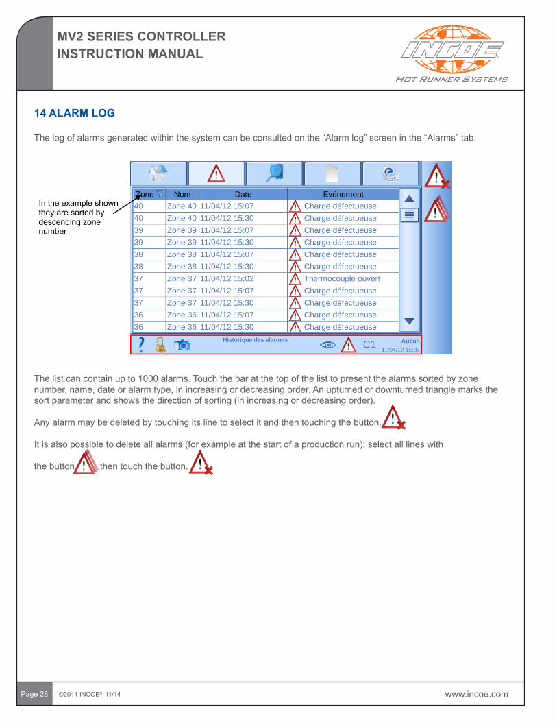
Thelogofalarmsgeneratedwithinthesystemcanbeconsultedonthe“Alarmlog”screeninthe“Alarms”tab.
In the example shown they are sorted by descending zone number
Thelistcancontainupto1000alarms.Touchthebaratthetopofthelisttopresentthealarmssortedbyzonenumber,name,dateoralarmtype,inincreasingordecreasingorder.Anupturnedordownturnedtrianglemarksthesortparameterandshowsthedirectionofsorting(inincreasingordecreasingorder).
Any alarm may be deleted by touching its line to select it and then touching the button.
Itisalsopossibletodeleteallalarms(forexampleatthestartofaproductionrun):selectalllineswith
the button then touch the button.
www.incoe.com ©2014 INCOE® 11/14
MV2 SERIES CONTROLLERINSTRUCTION MANUAL
Page29
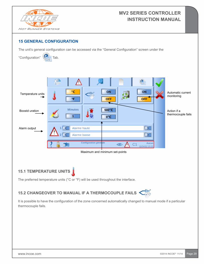
15 GENERAL CONFIGURATION
Theunit’sgeneralconfigurationcanbeaccessedviathe“GeneralConfiguration”screenunderthe
“Configuration”Tab.
Temperature units
Boostd uration
Alarm output
Maximum and minimum set-points
Automatic current monitoring
Action if a thermocouple fails
15.1 TEMPERATURE UNITS
Thepreferredtemperatureunits(°Cor°F)willbeusedthroughouttheinterface.
15.2 CHANGEOVER TO MANUAL IF A THERMOCOUPLE FAILS
Itispossibletohavetheconfigurationofthezoneconcernedautomaticallychangedtomanualmodeifaparticularthermocouple fails.
©2014 INCOE® 11/14 www.incoe.com
MV2 SERIES CONTROLLERINSTRUCTION MANUAL
Page30
15.3 AUTOMATIC CURRENT MONITORING
Ifthisoptionisactivated,thecontrolsystemcarriesout“MoldScan”rapidanalysesatintervalstodetectanyfaults.Forfurtherdetails(see13.8.1).
15.4 BOOST DURATION
ThedurationoftheBoostfunctioncanbesetinthisfield.Forfurtherdetailsonthisfunction(see13.5.5).
15.5 MAXIMUM AND MINIMUM SET-POINTS
Maximumandminimumset-pointscanbespecifiedforautomaticmode.
15.6 ALARM OUTPUT
Theunithastwo“Alarm”outputswhichcanbeusedtocontrolabuttonoranindicatorlight(see10.5).Whenandhowtheseoutputsarecontrolledcanbeconfiguredonthisscreen.Theoptionspossibleare:• HighTemperatureAlarm:theoutputisimplementedifazoneisintheHighTemperaturealarmstate.• LowTemperatureAlarm:theoutputisimplementedifazoneisintheLowTemperaturealarmstate.• HighorLowTemperatureAlarm:theoutputisimplementedifazoneisineithertheHighTemperatureortheLow
Temperature alarm state.• HighorLowTemperatureAlarm(exceptoninitialwarm-up):theoutputisimplementedifazoneisineithertheHigh
TemperatureortheLowTemperaturealarmstate,unlessthesystemiscarryingoutitsinitialwarm-up.• MoldScan:theoutputisimplementedifafaultisdetectedbyaMoldScanrapidanalysis(see13.9)orbypower
monitoring(see13.5.6).• All: the output is implemented if one of the conditions above occurs.
15.7 RESTORE FACTORY SETTINGS
Press the button to restore factory settings on the device. All control settings will be reset.
www.incoe.com ©2014 INCOE® 11/14
MV2 SERIES CONTROLLERINSTRUCTION MANUAL
Page 31
16 START-UP RAMPS
Onstart-up,thezonesunderautomaticmodeareheatedgraduallyuntiltheyreachtheiroperatingset-point.Therearefourpossibletypesofstart-upramp:
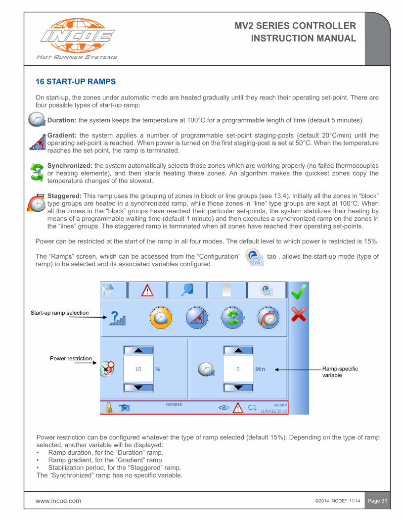
• Duration:thesystemkeepsthetemperatureat100°Cforaprogrammablelengthoftime(default5minutes).
• Gradient: the system applies a number of programmable set-point staging-posts (default 20°C/min) until theoperatingset-pointisreached.Whenpoweristurnedonthefirststaging-postissetat50°C.Whenthetemperaturereachestheset-point,therampisterminated.
• Synchronized: the system automatically selects those zones which are working properly (no failed thermocouples or heating elements), and then starts heating these zones.An algorithmmakes the quickest zones copy thetemperature changes of the slowest.
• Staggered:Thisrampusesthegroupingofzonesinblockorlinegroups(see13.4).Initiallyallthezonesin“block”typegroupsareheatedinasynchronizedramp,whilethosezonesin“line”typegroupsarekeptat100°C.Whenallthezonesinthe“block”groupshavereachedtheirparticularset-points,thesystemstabilizestheirheatingbymeansofaprogrammablewaitingtime(default1minute)andthenexecutesasynchronizedramponthezonesinthe“lines”groups.Thestaggeredrampisterminatedwhenallzoneshavereachedtheiroperatingset-points.
Powercanberestrictedatthestartoftherampinallfourmodes.Thedefaultleveltowhichpowerisrestrictedis15%.
The“Ramps”screen,whichcanbeaccessedfromthe“Configuration”tab,allowsthestart-upmode(typeoframp)tobeselectedanditsassociatedvariablesconfigured.
Powerrestrictioncanbeconfiguredwhateverthetypeoframpselected(default15%).Dependingonthetypeoframpselected,anothervariablewillbedisplayed:• Rampduration,forthe“Duration”ramp.• Rampgradient,forthe“Gradient”ramp.• Stabilizationperiod,forthe“Staggered”ramp.The“Synchronized”ramphasnospecificvariable.
Power restriction
Start-upramp selection
Ramp-specificvariable
©2014 INCOE® 11/14 www.incoe.com
MV2 SERIES CONTROLLERINSTRUCTION MANUAL
Page 32
17 CONFIGURATION FILES
17.1BEFORECREATINGACONFIGURATIONFILE(COMMISSIONINGAMOLD)
Configurationfilesenableyoutostorethewholeconfigurationoftheheatingsystemforagivenmoldandmanufacture.Itincludestheconfigurationofthecontrolzonesandanygroups,theunit’sgeneralconfiguration,thetypeoframpanditsconfiguration,andtheelectricalanalysisofthemold(savedreadings).
Beforecreatingaconfigurationfile,therefore,youshould:
1. Switchoffheatinginthezones:inthe“Regulation”tab,“Regulation”screen,selectallzones(selection
menuthen“SelectAll”)andswitchthemOff.
2. Configuretheunit:inthe“Configuration”tab,“GeneralConfiguration”screen,configurethevarious
optionsandconfirm.
3. Choosethetypeofstart-upramp:inthe“Configuration”tab,“Ramps”screen,selecttheramptype,
configurepowerrestrictionandtheramp’sspecificvariable,thenconfirm.
4. Configurethezonegroups(see13.4.1).
5. Configuretheheatingzones(see13.5).
6. TurnzoneheatingOn:inthe“Regulation”tab,“Regulation”screen,selectallzones(selectionmenu
then“SelectAll”)andstart.
7. Carryoutarapidorfullanalysisofthemold:inthe“MoldScan”tab,“Moldscanreadings”screen, selectallthezones(selectionmenuthen“SelectAll”)anddoarapidanalysisor
fullanalysis(notduringproduction).
8. Savethereadingsobtained.
Oncetheseoperationshavebeencompletedafilecanbecreatedinthe“FileConfiguration”screen(“Files”
tab).
www.incoe.com ©2014 INCOE® 11/14
MV2 SERIES CONTROLLERINSTRUCTION MANUAL
Page 33
17.1BEFORECREATINGACONFIGURATIONFILE(COMMISSIONINGAMOLD(CONT’D)
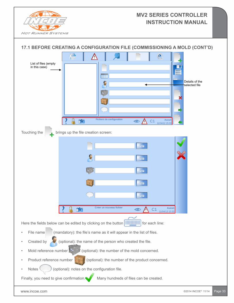
List of files (empty in this case)
Details of the selected file
Touchingthebringsupthefilecreationscreen:
Herethefieldsbelowcanbeeditedbyclickingonthebuttonforeachline:
• Filename(mandatory):thefile’snameasitwillappearinthelistoffiles.
• Createdby(optional):thenameofthepersonwhocreatedthefile.
• Moldreferencenumber(optional):thenumberofthemoldconcerned.
• Productreferencenumber(optional):thenumberoftheproductconcerned.
• Notes(optional):notesontheconfigurationfile.
Finally,youneedtogiveconfirmation.Manyhundredsoffilescanbecreated.
©2014 INCOE® 11/14 www.incoe.com
MV2 SERIES CONTROLLERINSTRUCTION MANUAL
Page 34
17.2 LOADING A CONFIGURATION FILE
Configurationfilesareloadedusingthe“FileConfiguration”screen(“Files”tab),selectingafileintheleft-handlist(thefile’snameishighlightedanditsdetailsappearinthefieldsontherightofthelist)andclickingontheLoadbutton.
Loading a file will delete and replace the unit’s current configuration.A confirmation dialogue will appear as aprecautionwhenafileisloaded.
17.3 UPDATING A CONFIGURATION FILE
Afile’scontentscanbeupdated:
1. Gotothe“FileConfiguration”screen(“Files”tab).
2. Loadthefiletobechanged.
3. Makethedesiredconfigurationchanges.
4. Gotothe“FileConfiguration”screen(“Files”tab).
5. Intheleft-handlistselectthefiletobechanged(thefile’snameishighlightedanditsdetailsappearinthefieldsontherightofthelist).
6. Touch the button.
Sincechangingafileinvolvesirretrievablydeletingtheoldconfiguration,aconfirmationdialoguewillappeareachtimeafileissaved.
17.4 DELETING A CONFIGURATION FILE
Todeleteaconfigurationfile:
1. Gotothe“FileConfiguration”screen(“Files”tab).
2. Intheleft-handlist,selectthefiletobedeleted(thefile’snameishighlightedanditsdetailsappearinthefieldsontherightofthelist).
3. Touch the button.
Sincedeletedfilesareirretrievable,aconfirmationdialoguewillappeareachtimeafileissaved.
17.5 COPYING A CONFIGURATION FILE
Tocopyaconfigurationfile:
1. Gotothe“FileConfiguration”screen(“Files”tab).
2. Loadthefiletobecopied.
3. Touch the button. 4. Completetheformwithadifferentfilename
5. Confirm.
www.incoe.com ©2014 INCOE® 11/14
MV2 SERIES CONTROLLERINSTRUCTION MANUAL
Page35
17.6 EXPORTING AND IMPORTING CONFIGURATION FILES WITH A USB STICK
AconfigurationfilecanonlybeexportedtoorimportedfromaUSBstickoncetheUSBstick(oraUSBharddisk)hasbeenconnectedtotheunitusingtheUSBportonthefront.
Oncetheperipheralhasbeenconnected,theandbuttonswillappearintheActionsbarofthe“FileConfiguration”screen(“Files”tab).
17.6.1 EXPORT A FILE
Toexportaconfigurationfile:
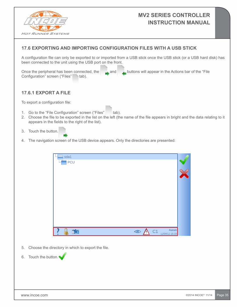
1. Gotothe“FileConfiguration”screen(“Files”tab).2. Choosethefiletobeexportedinthelistontheleft(thenameofthefileappearsinbrightandthedatarelatingtoit
appearsinthefieldstotherightofthelist).
3. Touch the button.
4. ThenavigationscreenoftheUSBdeviceappears.Onlythedirectoriesarepresented:
5. Choosethedirectoryinwhichtoexportthefile.
6. Touchthebutton.
©2014 INCOE® 11/14 www.incoe.com
MV2 SERIES CONTROLLERINSTRUCTION MANUAL
Page36
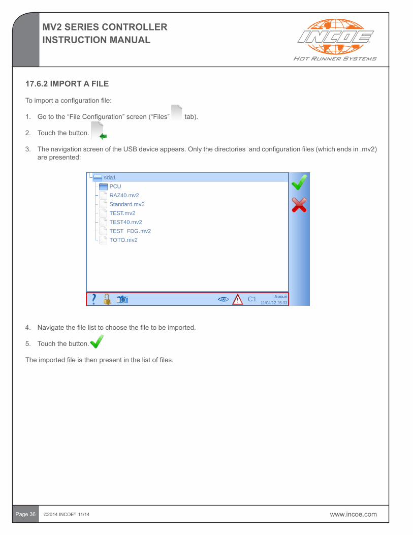
4. Navigatethefilelisttochoosethefiletobeimported.
5. Touchthebutton.
Theimportedfileisthenpresentinthelistoffiles.
17.6.2 IMPORT A FILE
Toimportaconfigurationfile:
1. Gotothe“FileConfiguration”screen(“Files”tab).
2. Touch the button. 3. ThenavigationscreenoftheUSBdeviceappears.Onlythedirectoriesandconfigurationfiles(whichendsin.mv2)
are presented:
www.incoe.com ©2014 INCOE® 11/14
MV2 SERIES CONTROLLERINSTRUCTION MANUAL
Page 37
18 REGIONAL PARAMETERS
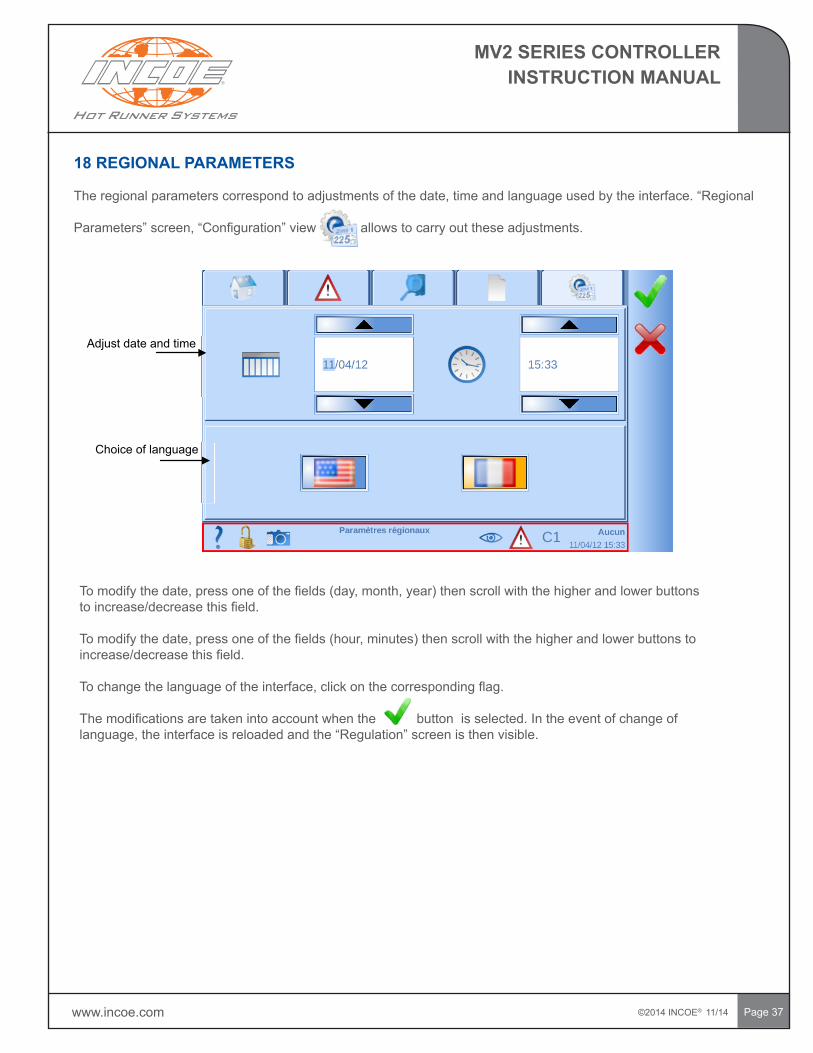
Theregionalparameterscorrespondtoadjustmentsofthedate,timeandlanguageusedbytheinterface.“Regional
Parameters”screen,“Configuration”viewallowstocarryouttheseadjustments.
Adjust date and time
Choice of language
Tomodifythedate,pressoneofthefields(day,month,year)thenscrollwiththehigherandlowerbuttonstoincrease/decreasethisfield.
Tomodifythedate,pressoneofthefields(hour,minutes)thenscrollwiththehigherandlowerbuttonstoincrease/decreasethisfield.
Tochangethelanguageoftheinterface,clickonthecorrespondingflag.
Themodificationsaretakenintoaccountwhenthebuttonisselected.Intheeventofchangeoflanguage,theinterfaceisreloadedandthe“Regulation”screenisthenvisible.
©2014 INCOE® 11/14 www.incoe.com
MV2 SERIES CONTROLLERINSTRUCTION MANUAL
Page38
19 MAINTENANCE INSTRUCTIONS
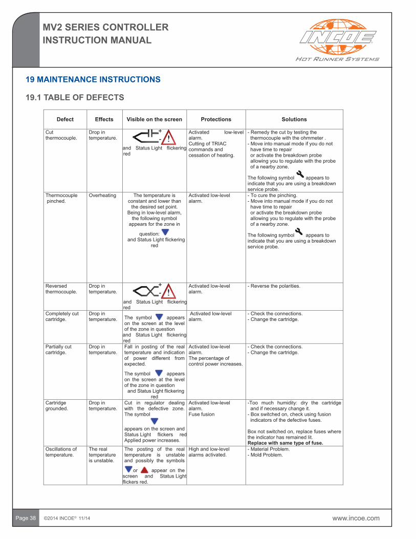
19.1 TABLE OF DEFECTS
Defect Effects Visible on the screen Protections Solutions
Cut thermocouple.
Drop in temperature.
and Status Light flickering red
Activated low-level alarm.Cutting of TRIAC commands and cessation of heating.
- Remedy the cut by testing the thermocouple with the ohmmeter .
- Move into manual mode if you do not have time to repairor activate the breakdown probe allowing you to regulate with the probe of a nearby zone.
The following symbol appears to indicate that you are using a breakdown service probe.
Thermocouplepinched.
Overheating The temperature is constant and lower than
the desired set point.Being in low-level alarm,
the following symbol appears for the zone in
question: and Status Light flickering
red
Activated low-level alarm.
- To cure the pinching. - Move into manual mode if you do not
have time to repairor activate the breakdown probe allowing you to regulate with the probe of a nearby zone.
The following symbol appears to indicate that you are using a breakdown service probe.
Reversed thermocouple.
Drop in temperature.
and Status Light flickering red
Activated low-level alarm.
- Reverse the polarities.
Completely cut cartridge.
Drop in temperature. The symbol appears
on the screen at the level of the zone in question
and Status Light flickering red
Activated low-level alarm.
- Check the connections.- Change the cartridge.
Partially cut cartridge.
Drop in temperature.
Fall in posting of the real temperature and indication of power different from expected.
The symbol appears on the screen at the level of the zone in question
and Status Light flickering red
Activated low-level alarm.The percentage of control power increases.
- Check the connections.- Change the cartridge.
Cartridge grounded.
Drop in temperature.
Cut in regulator dealing with the defective zone. The symbol
appears on the screen and Status Light flickers red. Applied power increases.
Activated low-level alarm.Fuse fusion
-Too much humidity: dry the cartridge and if necessary change it.
- Box switched on, check using fusion indicators of the defective fuses.
Box not switched on, replace fuses where the indicator has remained lit.Replace with same type of fuse.
Oscillations of temperature.
The real temperature is unstable.
The posting of the real temperature is unstable and possibly the symbols
or appear on the screen and Status Lightflickers red.
High and low-level alarms activated.
- Material Problem.- Moldl Problem.
www.incoe.com ©2014 INCOE® 11/14
MV2 SERIES CONTROLLERINSTRUCTION MANUAL
Page39
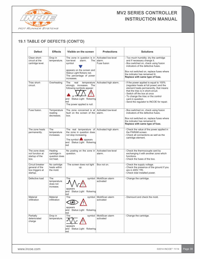
19.1TABLEOFDEFECTS(CONT’D)
Clean short-circuit at the cartridge level.
Drop in temperature.
The zone in question is in low-level alarm. The symbol
appears on the screen and Status Light flickers red.The percentage of power increases.
Activated low-level alarm.Fuse fusion
- Too much humidity: dry the cartridge and if necessary change it.
- Box switched on, check using fusion indicators of the defective fuses.
Box not switched on, replace fuses where the indicator has remained lit.Replace with same type of fuse.
Triac short-circuit.
Overheating The real temperature strongly increases. The following symbols appear:
or and Status Light flickering redThe power applied is null.
Activated high alarm. - If the power applied is equal to 100% (regulator heats at full power) and the element heats permanently, that means that the triac is in short-circuit.
- Switch off the box at once- To change the triac or the control
card in question.- Send the regulator to INCOE for repair.
Fuse fusion. Temperature reading decreases.
The zone concerned is at fault on the screen of the box.
Activated low-level alarm.
- Box switched on, check using fusion indicators of the defective fuses.
Box not switched on, replace fuses where the indicator has remained lit.Replace with same type of fuse.
The zone heats permanently.
The temperature increases.
The real temperature of the zone in question does not stop increasing.
The symbol appearsand Status Light flickering red
Activated high alarm. - Check the value of the power applied in the PARAM screen.
- Check all connections as well as the cartridge element.
The zone does not function at startup of the box.
Heating cartridge in question does not heat.
No posting on the zone in question.
Activated low-level alarm.
- Check the thermocouple card by exchanging it with another zone which functions.
- Check the fuses of the box.
Circuit breaker general of the box triggers at startup.
No cartridge heats within the mold.
The screen does not light up.
Box not on. - Check the supply voltage.- Check the presence of the ground if you
are in 400V TRI.- Check total installed power.
Defective load The temperature does not increase.
The symbol
appears and Status Light flickering red
MoldScan alarm activated
- Change the cartridge.
Material infiltration
Material infiltration
The symbol
appearsand Status Light flickering red
MoldScan alarm activated
- Dismount and check the mold.
Partially deteriorated charge
Drop in temperature.
The symbol
appears and Status Light flickering red
MoldScan alarm activated
- Change the cartridge.
Defect Effects Visible on the screen Protections Solutions
©2014 INCOE® 11/14 www.incoe.com
MV2 SERIES CONTROLLERINSTRUCTION MANUAL
Page40
PROCEDURE TO BE FOLLOWED FOR INJECTION CONTROLS
Example of breakdown: a mold zone does not go up to the desired set point.
Lookatthenumberofthezoneatfault.
Gotothe“Regulation”screen,“Regulation”viewand modify the level of zoom to reveal the power applied(redbar).Checkifthebarisatmaximum.
If the power applied posted on the screen is equal to 100% and the zone is still not heating that can come from 3 causes:
• The element to be heated is oversized compared to whattheINCOEpowercardcandeliverandinthemedium-termthefuseswillroast.(Max.intensity,16Aor15Aaccordingtoversions).
• The power card has 2 fuses (one on the phase and the other on the ground. Perhaps both or only one is defective.
• There is between the exit of the power card and the connection in the mold a disconnected or badly connected wire. The element can be also defective.
Beyondtheseobservations,anyinterventioninsidetheSeriesMboxesmustbemadebyacompetentperson.
PROCEDURE TO BE FOLLOWED BY THE MAINTENANCE PERSONNEL
Example of breakdown: a mold zone does not go up to the desired set point.
Visualize the defect on the zone in question on the “Regulation”screen,“Regulation”view.
Detect the site of the power card corresponding to thezoneatfault.Onthisonethereare2indicatorsoffuse fusion which are located beneath each fuse. They indicate whether one of the two fuses is out of service.
Ifyouseeoneorthetwoindicatorsareon,thatmeansthatthefuse(s)shouldbechanged.
Warning: use the same type of fuse according to the power card version.
Ifnoindicatorignites,switch off the box using the circuit breaker. Usingatester,checkifthefusesaregood(iftheindicatorsoffusionareoutofservice).
Ifthefusesaregood,then switch the box back on.Verifyusingthetesterwhetherthereis230VACvoltage at the exit of the power card (at the level of the 2blueorredclipsdependingontheversions).Note: it is necessary that the zone is in manual mode with a setpointequalto100%andthattheotherzonesareallswitchedOFF.
Ifthereis230VAC,thismeansthatthebreakdowndoes not come from the power card.
Switch off the box. Test the continuity of wires betweentheexitsonclips,thehartingplugsatthebackof the box and the wiring at mold level.
IMPORTANT NOTE: Duringoperation,duringthephase of rise in temperature of the regulators and according to the percentage of power used by each regulator,it may be that the intensity of the ground is higher than the intensity on one of the three phases. This overcurrent is controlled by the principal circuit breaker located at the back of the contoller. Power consumption depends on the nominal power output of heated elements and the number of regulators used.
In addition:
• Any intervention on the device will have to be carried out by a competent person.
• Any changed part must have the same characteristics.
• Controller must be disconnected from power source before performing maintenance inside of the enclosure.
www.incoe.com ©2014 INCOE® 11/14
MV2 SERIES CONTROLLERINSTRUCTION MANUAL
Page 41
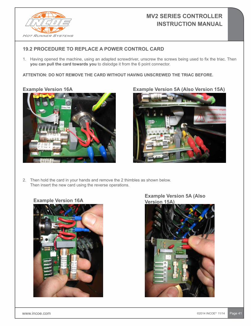
19.2 PROCEDURE TO REPLACE A POWER CONTROL CARD
1. Havingopenedthemachine,usinganadaptedscrewdriver,unscrewthescrewsbeingusedtofixthetriac.Thenyou can pull the card towards youtodislodgeitfromthe6pointconnector.
ATTENTION: DO NOT REMOVE THE CARD WITHOUT HAVING UNSCREWED THE TRIAC BEFORE.
Example Version 16A ExampleVersion5A(AlsoVersion15A)
2. Then hold the card in your hands and remove the 2 thimbles as shown below. Then insert the new card using the reverse operations.
Example Version 16AExampleVersion5A(AlsoVersion15A)
©2014 INCOE® 11/14 www.incoe.com
MV2 SERIES CONTROLLERINSTRUCTION MANUAL
Page 42
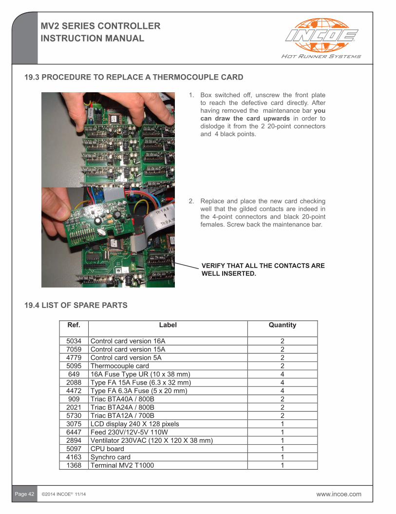
19.3 PROCEDURE TO REPLACE A THERMOCOUPLE CARD
1. Box switched off, unscrew the front plateto reach the defective card directly. After having removed the maintenance bar you can draw the card upwards in order to dislodge it from the 2 20-point connectorsand 4 black points.
2. Replace and place the new card checking well that the gilded contacts are indeed in the 4-point connectors and black 20-pointfemales.Screwbackthemaintenancebar.
VERIFY THAT ALL THE CONTACTS ARE WELL INSERTED.
Ref. Label Quantity
5034 Control card version 16A 27059 Control card version 15A 24779 Control card version 5A 25095 Thermocouple card 2649 16A Fuse Type UR (10 x 38 mm) 4
2088 Type FA 15A Fuse (6.3 x 32 mm) 44472 Type FA 6.3A Fuse (5 x 20 mm) 4909 Triac BTA40A / 800B 2
2021 Triac BTA24A / 800B 25730 Triac BTA12A / 700B 23075 LCD display 240 X 128 pixels 16447 Feed 230V/12V-5V 110W 12894 Ventilator 230VAC (120 X 120 X 38 mm) 15097 CPU board 14163 Synchro card 11368 Terminal MV2 T1000 1
19.4 LIST OF SPARE PARTS
www.incoe.com ©2014 INCOE® 11/14
MV2 SERIES CONTROLLERINSTRUCTION MANUAL
Page 43
20 PARTIAL SUMMARY OF EXPRESS WARRANTY
INCOECORPORATIONwarrantsproducts(orportionsthereof)itmanufacturestobefreefromdefectsinmaterialand workmanship for the periods given in the table below. The warranty term is measured from the date of shipment fromINCOEtotheextentprovidedintheINCOEGeneralTermsandConditionsofSalereferencedbelow(“INCOEWarranty”).INCOE’sexclusiveobligationandbuyer’sexclusiveremedyundertheINCOEWarrantyislimitedtorepair(byINCOEorINCOE’sdesignatedrepresentative)orreplacementofparts,FOBINCOE,atINCOE’sdiscretion.
INCOEwillassigntocustomerswhateverassignablewarrantyINCOEreceivesonproductsoldbyINCOEbutnotmanufacturedbyINCOE.TheINCOEWarrantyandtherepairorreplacementremedyonINCOEmanufacturedproductandINCOE’sobligationsonallproductsoldbyINCOEaresubjecttofurtherconditions,limitationsanddisclaimersofimpliedwarrantiescontainedinINCOE’sGeneralTermsandConditionsofSale,whicharelocatedonourwebsite www.INCOE.com.Thesearesubjecttochangewithoutnoticepriortoanysale.Thus,thisPartialSummaryisnotabindingdocument.TheINCOEWarrantydoesnotcover,forexampleonly,thefollowing:
• Repairorreplacementduetonormalwear,ordamagecausedduringroutinemaintenanceoruse.• Damagefromfailuretofollowrecommendedmaintenanceandoperatingprocedures,asoutlinedinanyapplicable
INCOEmanual.• DamagearisingfrommodificationsnotincludedintheproceduresinanyapplicableINCOEmanual.• Damage to components due to product or mold design.• Damageresultingfromtheuseofunauthorizedparts,orauthorizedpartswhicharesupplied,manufacturedor
modifiedbyproceduresnotincludedinanyapplicableINCOEmanualandthepartslist.• Consequentialloss,personalinjury,damagetogoodsand/orequipment,workstoppages,delays,orslowdowns
in production.• Transportation charges and local sales taxes for replaced or repaired parts.• Expenses resulting from meeting local codes and standards.• Normalmaintenanceandperishableitems.
TheINCOEWarrantyappliesonlytotheoriginalmoldownerforhotrunners,heatersandthermocouplesandtheoriginalownerforcontrollers,andisnon-transferable.IfreplacementpartsaretobefurnishedundertheINCOEWarranty,thecustomermustsubmitapurchaseorderforthereplacementpartsandreturnthefailedparttoINCOE.Replacement product will be sent promptly on receipt of purchase order. Upon return of the part and approval by INCOE,acreditmemowillbeissuedifpartiscoveredunderINCOEWarranty.Failuretoreturndefectivepartwithin30daysofreceiptofreplacementpartwillresultinrejectionofthewarrantyclaimandthewaiverofanysuchclaims.
PartsmaynotbereturnedwithoutareturnauthorizationnumberfromINCOE.ReturnedpartsmustbeproperlyidentifiedwithatagshowingINCOEjobnumber,returnauthorizationnumberanddate,andbepackagedsoastoavoidfurtherdamageinshipping,andshippedtothelocationspecifiedbyINCOE.
TheINCOEWarrantymaybesupersededonlybyaspecificindividualcontractsignedbyanINCOEofficer.
#226031.3(Rev.10/9/14)RST
Compression Nozzle System &
Components1 Year
Thermocouples, Valve Gate Sleeve Seals(PinSeals),ValveGateSeals,Tips&
Valve Pins6 Months
Threaded Nozzle Systems, Unitized
Systems & Components
3 Years Leak Free1 Year Components Controllers(Temperatures/ValveGate) 2 Years
Nozzle Heaters 3 Years
©2014 INCOE® 11/14 www.incoe.com
MV2 SERIES CONTROLLERINSTRUCTION MANUAL
Page 44
21 GLOBAL OFFICES & SERVICE CONTACTSIncaseofproblemorforanyfurtherinformation,pleaseusethecontactinformationbelow,orvisitwww.incoe.com.
GLOBAL HEADQUARTERSINCOE® NORTH AMERICA
INCOE® Corporation1740EastMapleRoadTroy,Michigan48083USA
MainT:+1(248)616-0220F:+1(248)616-0225E: [email protected]
SalesT:+1(248)556-7770F:+1(248)616-0227E: [email protected]
SupportT:+1(248)556-7790F:+1(248)556-7799E: [email protected]
INCOE® EUROPE
INCOE® International EuropeCarl-Zeiss-Straße33D-63322RödermarkGermany
Sales & SupportT:+49(0)6074-8907-0F:+49(0)6074-8907-310E: [email protected]
INCOE® CHINA | SHANGHAI
INCOE® Hotrunners(Shanghai)Co.,Ltd.399XuanzhongRoad,Building16PudongNewAreaShanghai201314China
Sales & SupportT:+86(21)5818-6300F:+86(21)5818-6303E: [email protected]
INCOE® SOUTH AMERICA
INCOE® International Brasil, Ltda.RuaEugenioUlhano,335Jardim VirginiaItatiba,SP13257-480Brasil
Sales & SupportT:+55(11)4538-2445F:+55(11)4524-5690E: [email protected]
INCOE® HONG KONG
INCOE® (H.K.)LTD.1205LeaderIndustrialCentre57-59AuPuiWanStreetFoTan,Shatin,N.T.HongKong
Sales & SupportT:+8522790-8840F:+8522790-8411E: [email protected]
INCOE® CHINA | DONGGUAN BRANCH OFFICE
INCOE® Hotrunners(Shanghai)Co.,Ltd.RoomB,5/F,HaoYunBuilding2ndHuanRoadChanganTown,DongguanGuangdong,China
Sales & SupportT:+86(769)8535-5881F:+86(769)8542-2998E: [email protected]
INCOE® SINGAPORE
INCOE® Singapore Pte Ltd.8,BonLayWay#04-07TradeHub21Singapore609964Singapore
Sales & SupportT:+65(6)515-5300F:+65(6)861-1163E: [email protected]

©2014 INCOE® 10/14
PDF copies of this manual are available for download on our website at: www.incoe.com.
Recommended