Eastern Interconnection Reliability Assessment Group
ERAG
Multi-regional Modeling Working Group Case Building Process
Presented by,
John Idzior ReliabilityFirst Corporation
NERC Modeling Workshop Minneapolis, MN
October 1-3, 2012
Eastern Interconnection Reliability Assessment Group
ERAG ERAG Structure
• Agreement signed by 6 EI Regional Managers
• Management Committee MMWG Regional Entity Coordinators
Other Representatives
Study Steering Committee 3 Working Groups
10/24/2012 2
Eastern Interconnection Reliability Assessment Group
ERAG Regional Coordinators
• FRCC (Fred McNeil, John Shaffer)
• MRO (Adam Flink)
• NPCC (Donal Kidney)
• RFC (John Idzior)
• SERC (Lee Adams, John Sullivan)
• SPP (Anthony Cook, Scott Jordon)
10/24/2012 3
Eastern Interconnection Reliability Assessment Group
ERAG Annual Development
• Series of Base Cases Power Flow 13 Cases
Dynamics 8 Cases
• Master Tie Line List
• Interchange Schedule
• Procedure Manual
10/24/2012 4
Eastern Interconnection Reliability Assessment Group
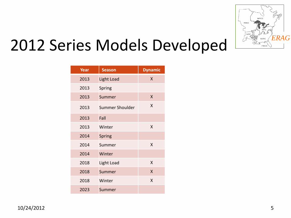
ERAG 2012 Series Models Developed
Year Season Dynamic
2013 Light Load X
2013 Spring
2013 Summer X
2013 Summer Shoulder X
2013 Fall
2013 Winter X
2014 Spring
2014 Summer X
2014 Winter
2018 Light Load X
2018 Summer X
2018 Winter X
2023 Summer
10/24/2012 5
Eastern Interconnection Reliability Assessment Group
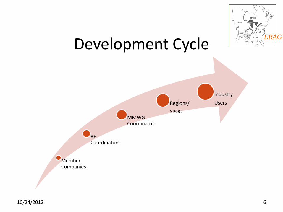
ERAG Development Cycle
Member Companies
RE Coordinators
MMWG Coordinator
Regions/
SPOC
Industry
Users
10/24/2012 6
Eastern Interconnection Reliability Assessment Group
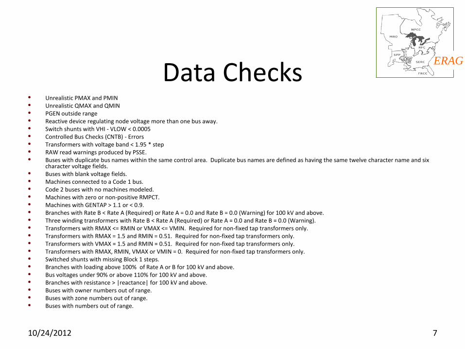
ERAG Data Checks
• Unrealistic PMAX and PMIN • Unrealistic QMAX and QMIN • PGEN outside range • Reactive device regulating node voltage more than one bus away. • Switch shunts with VHI - VLOW < 0.0005 • Controlled Bus Checks (CNTB) - Errors • Transformers with voltage band < 1.95 * step • RAW read warnings produced by PSSE. • Buses with duplicate bus names within the same control area. Duplicate bus names are defined as having the same twelve character name and six
character voltage fields. • Buses with blank voltage fields. • Machines connected to a Code 1 bus. • Code 2 buses with no machines modeled. • Machines with zero or non-positive RMPCT. • Machines with GENTAP > 1.1 or < 0.9. • Branches with Rate B < Rate A (Required) or Rate A = 0.0 and Rate B = 0.0 (Warning) for 100 kV and above. • Three winding transformers with Rate B < Rate A (Required) or Rate A = 0.0 and Rate B = 0.0 (Warning). • Transformers with RMAX <= RMIN or VMAX <= VMIN. Required for non-fixed tap transformers only. • Transformers with RMAX = 1.5 and RMIN = 0.51. Required for non-fixed tap transformers only. • Transformers with VMAX = 1.5 and RMIN = 0.51. Required for non-fixed tap transformers only. • Transformers with RMAX, RMIN, VMAX or VMIN = 0. Required for non-fixed tap transformers only. • Switched shunts with missing Block 1 steps. • Branches with loading above 100% of Rate A or B for 100 kV and above. • Bus voltages under 90% or above 110% for 100 kV and above. • Branches with resistance > |reactance| for 100 kV and above. • Buses with owner numbers out of range. • Buses with zone numbers out of range. • Buses with numbers out of range.
10/24/2012 7
Eastern Interconnection Reliability Assessment Group
ERAG Case Distribution
• ERAG Base Case Release Procedure (NDA)
• Regional Entity Members - Regional Coordinator
• Third Party Users - Single Point of Contact - ReliabilityFirst Corporation
• Secure Site
• Public Site - erag.info
10/24/2012 8
Eastern Interconnection Reliability Assessment Group
ERAG Software Tools Used
• Siemens PTI PSS/e
• Powertech Labs, Inc. Power Flow Database (PFDB)
Dynamics Database (SDDB)
10/24/2012 9

Eastern Interconnection Reliability Assessment Group
ERAG
10/24/2012 10
Questions?

Eastern Interconnection Reliability Assessment Group
ERAG
John Idzior
Lead Engineer, Modeling
ReliabilityFirst Corporation
330-247-3059
10/24/2012 11
Nitika Mago, P.E. Network Model Administration
NERC Modeling Workshop Bloomington, MN
Oct. 1, 2012
Network Modeling The ERCOT Experience
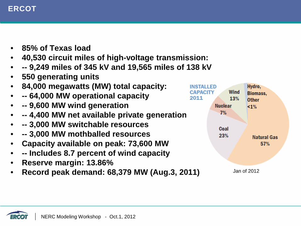
ERCOT
• 85% of Texas load • 40,530 circuit miles of high-voltage transmission: • -- 9,249 miles of 345 kV and 19,565 miles of 138 kV • 550 generating units • 84,000 megawatts (MW) total capacity: • -- 64,000 MW operational capacity • -- 9,600 MW wind generation • -- 4,400 MW net available private generation • -- 3,000 MW switchable resources • -- 3,000 MW mothballed resources • Capacity available on peak: 73,600 MW • -- Includes 8.7 percent of wind capacity • Reserve margin: 13.86% • Record peak demand: 68,379 MW (Aug.3, 2011)
Jan of 2012
NERC Modeling Workshop - Oct.1, 2012
Network Modeling Overview
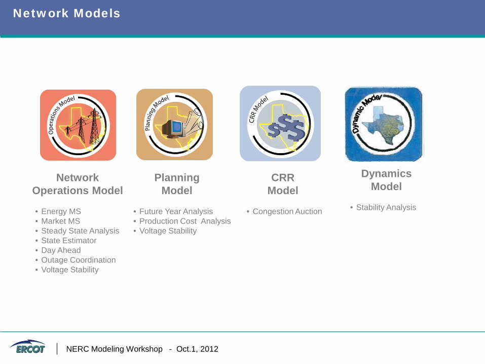
Network Models
Planning Model
• Future Year Analysis • Production Cost Analysis • Voltage Stability
Network Operations Model
• Energy MS • Market MS • Steady State Analysis • State Estimator • Day Ahead • Outage Coordination • Voltage Stability
CRR Model
• Congestion Auction
Dynamics Model
• Stability Analysis
NERC Modeling Workshop - Oct.1, 2012
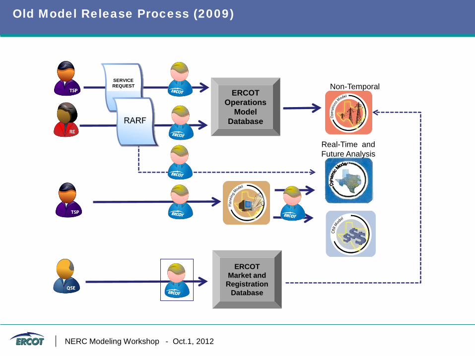
Old Model Release Process (2009)
Real-Time and Future Analysis
ERCOT Operations
Model Database
Non-Temporal
ERCOT Market and
Registration Database
SERVICE REQUEST
NERC Modeling Workshop - Oct.1, 2012
Problems with the Old Process
• Single Operations Model only valid for 2 weeks in advance. Planning Models were for following year, leaving a study gap.
• Market Information not integrated in Operations Model.
• Contingency files and One-lines not available to support future studies.
• Model database and Outage Scheduler had no dynamic link resulting in “broken” outages and no ability to outage future equipment.
• Differences in Planning and Operation Model topologies, element attributes, and naming conventions.
• Dynamic cases built from Planning Cases, but used to support decisions made in real-time.
• Market Participants had no access to the Model Database.
NERC Modeling Workshop - Oct.1, 2012
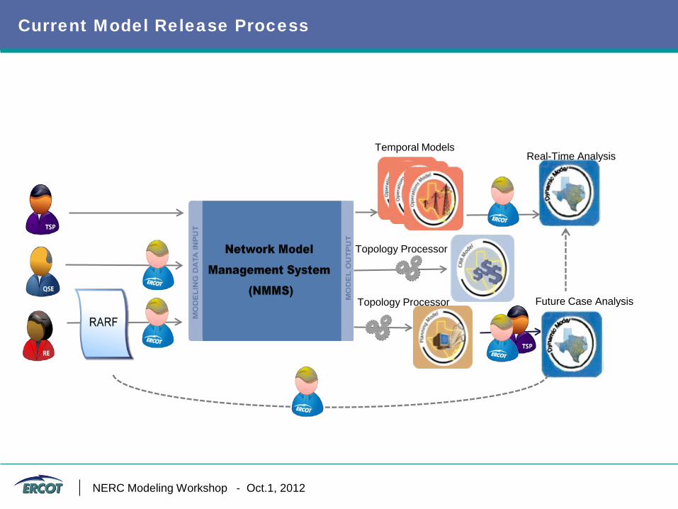
Current Model Release Process
Topology Processor
Topology Processor
Real-Time Analysis Temporal Models
Future Case Analysis
NERC Modeling Workshop - Oct.1, 2012
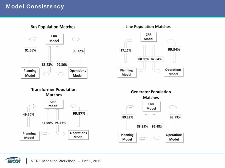
Model Consistency
NERC Modeling Workshop - Oct.1, 2012
Network Model Management System
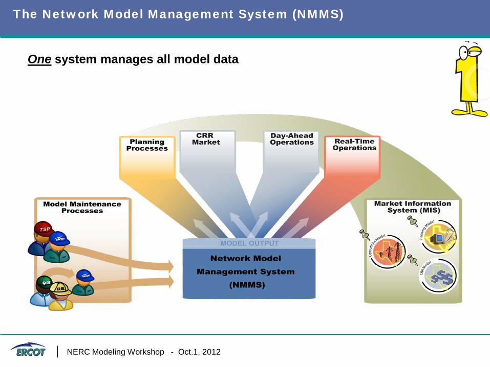
The Network Model Management System (NMMS)
One system manages all model data
NERC Modeling Workshop - Oct.1, 2012
What is NMMS?
The Network Model Management System (NMMS) is an umbrella of applications used to manage, manipulate, prepare, validate, test, and provide consistent models to all model-driven ERCOT operational, market and planning systems. • Utilizes Common Information Model (CIM) standards for integration.
• Built around the Siemens’ Information Model Manager (IMM) and
Model on Demand (MOD)
• Uses temporal based tracking methodologies to store the network models data changes.
• NMMS serves as the single point of entry and maintenance for the network model topology used by external ERCOT market participants.
NERC Modeling Workshop - Oct.1, 2012
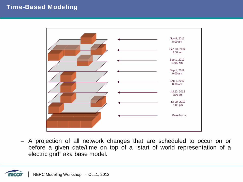
Time-Based Modeling
Base Model
Jul 20, 2012 1:00 pm
Jul 20, 2012 2:00 pm
Sep 1, 2012 8:00 am
Sep 1, 2012 9:00 am
Sep 1, 2012 10:00 am
Sep 30, 2012 9:00 am
Nov 8, 2012 8:00 am
– A projection of all network changes that are scheduled to occur on or before a given date/time on top of a “start of world representation of a electric grid” aka base model.
NERC Modeling Workshop - Oct.1, 2012
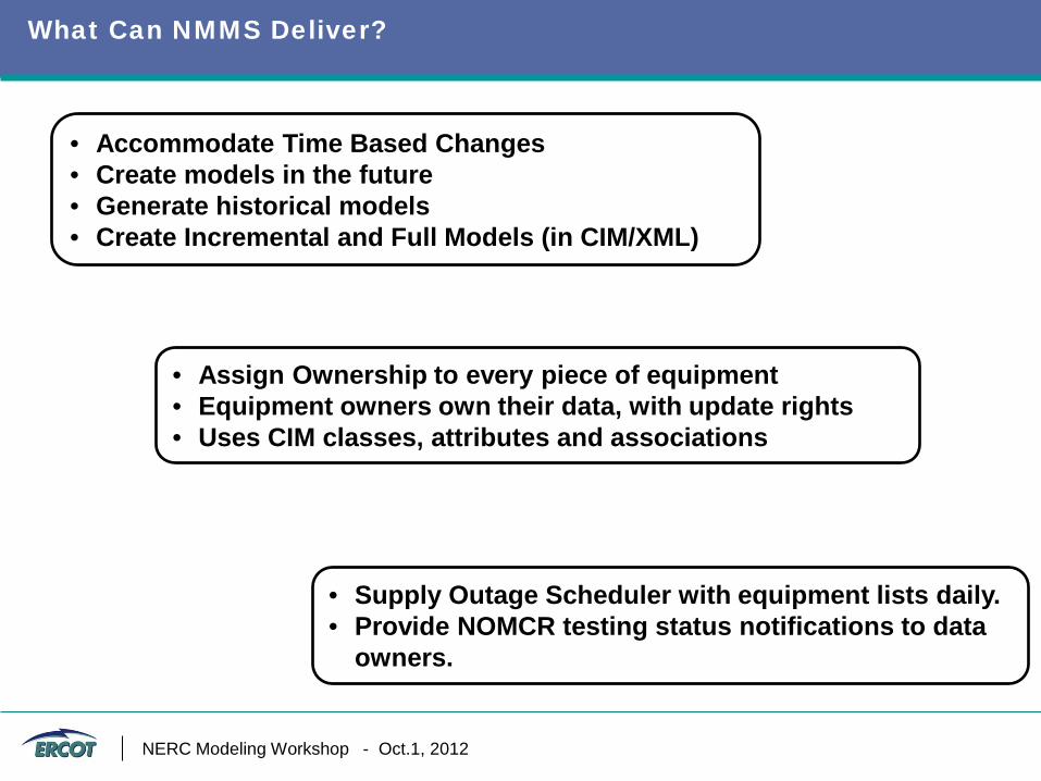
What Can NMMS Deliver?
• Accommodate Time Based Changes • Create models in the future • Generate historical models • Create Incremental and Full Models (in CIM/XML)
• Assign Ownership to every piece of equipment • Equipment owners own their data, with update rights • Uses CIM classes, attributes and associations
• Supply Outage Scheduler with equipment lists daily. • Provide NOMCR testing status notifications to data
owners.
NERC Modeling Workshop - Oct.1, 2012
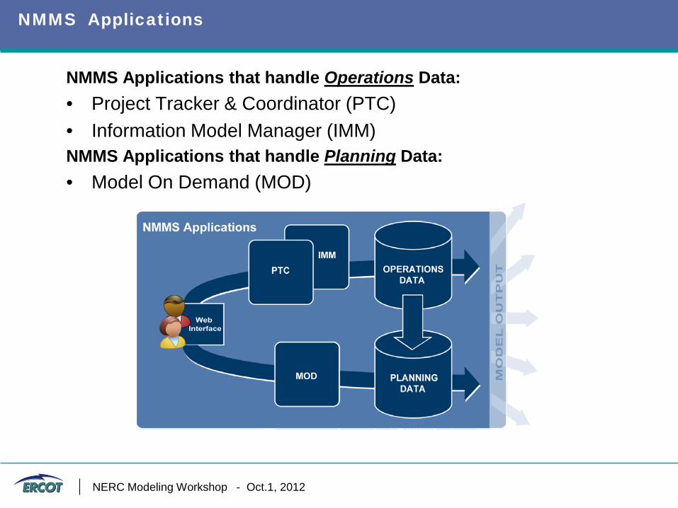
NMMS Applications
NMMS Applications that handle Operations Data: • Project Tracker & Coordinator (PTC) • Information Model Manager (IMM) NMMS Applications that handle Planning Data: • Model On Demand (MOD)
Introduction : Slide 14 NERC Modeling Workshop - Oct.1, 2012
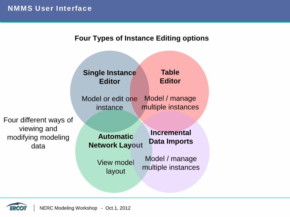
Four Types of Instance Editing options
NMMS User Interface
Single Instance Editor
Model or edit one
instance
Table Editor
Model / manage
multiple instances
Automatic Network Layout
View model
layout
Four different ways of viewing and
modifying modeling data
Module 2 : Slide 15
Incremental Data Imports
Model / manage
multiple instances
NERC Modeling Workshop - Oct.1, 2012
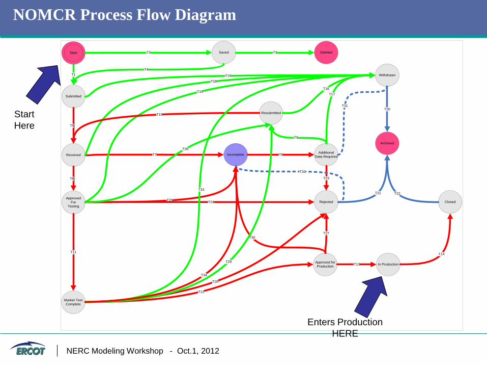
NOMCR Process Flow Diagram
Start Saved
Submitted
Deleted
Received
RejectedApproved
ForTesting
Incomplete
Withdrawn
AdditionalData Required
Approved forProduction In Production
Closed
T13
T14
Archived
T22
T20
T21
T25
T1
T2
T4
T3
T15
T5
T6
T7 T8
Resubmitted
T9
T16T19
Market TestComplete
T11
T12
T23
T27
T26
T24
T28
T18
T17
T10
T30
T29
T31
T32
T33
T34
Start Here
Enters Production HERE
NERC Modeling Workshop - Oct.1, 2012
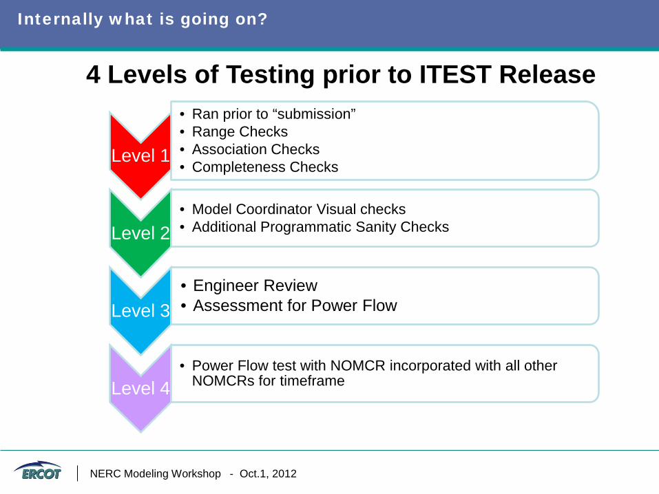
Internally what is going on?
4 Levels of Testing prior to ITEST Release
Level 1
• Ran prior to “submission” • Range Checks • Association Checks • Completeness Checks
Level 2 • Model Coordinator Visual checks • Additional Programmatic Sanity Checks
Level 3 • Engineer Review • Assessment for Power Flow
Level 4 • Power Flow test with NOMCR incorporated with all other
NOMCRs for timeframe
NERC Modeling Workshop - Oct.1, 2012
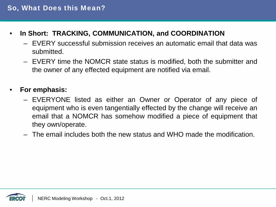
So, What Does this Mean?
• In Short: TRACKING, COMMUNICATION, and COORDINATION – EVERY successful submission receives an automatic email that data was
submitted. – EVERY time the NOMCR state status is modified, both the submitter and
the owner of any effected equipment are notified via email.
• For emphasis: – EVERYONE listed as either an Owner or Operator of any piece of
equipment who is even tangentially effected by the change will receive an email that a NOMCR has somehow modified a piece of equipment that they own/operate.
– The email includes both the new status and WHO made the modification.
NERC Modeling Workshop - Oct.1, 2012
NMMS Facts
• Since 9/1/2009 NMMS is being used as the primary system to enter network model changes by ERCOT’s Market Participants and by ERCOT. – 16000+ change requests have been submitted into NMMS thus far. – Weekly CIM models from NMMS have been delivered to downstream
test environments.
• Since 6/1/2012 NMMS is being used as the source of record for planning models and planning model changes by ERCOT’s Market Participants and by ERCOT staff to build future planning cases. – Planners are now using NMMS to build base models for 5-year studies
• Quiet a few tools leveraging the flat structure of CIM/XML have been
developed. Some notable ones include, – Model topology tracer for Outage Scheduler, – Contingency definition builder, – Station one-line editor/generator, and – Granular model comparison viewer
NERC Modeling Workshop - Oct.1, 2012
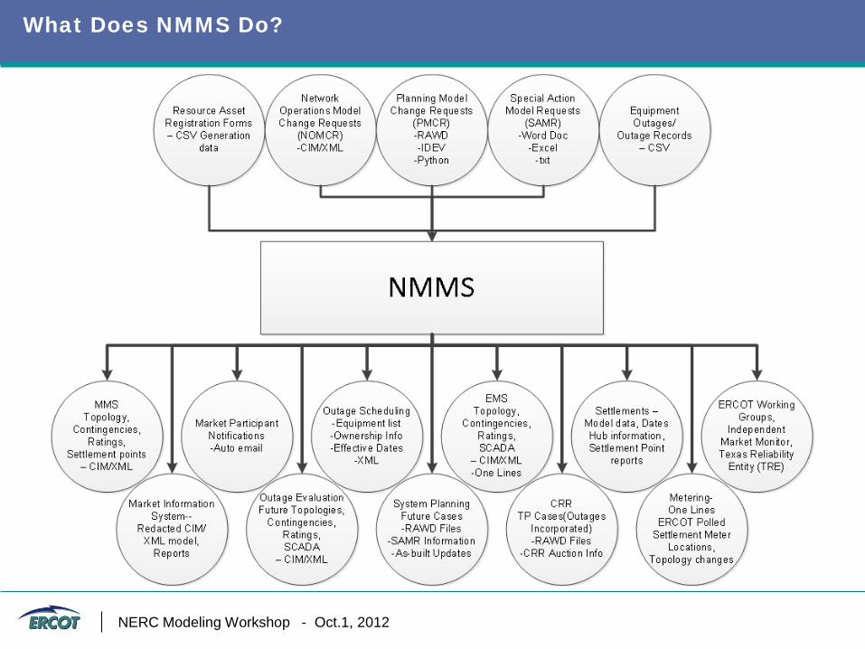
What Does NMMS Do?
NERC Modeling Workshop - Oct.1, 2012
Building Network Models for Planning Studies
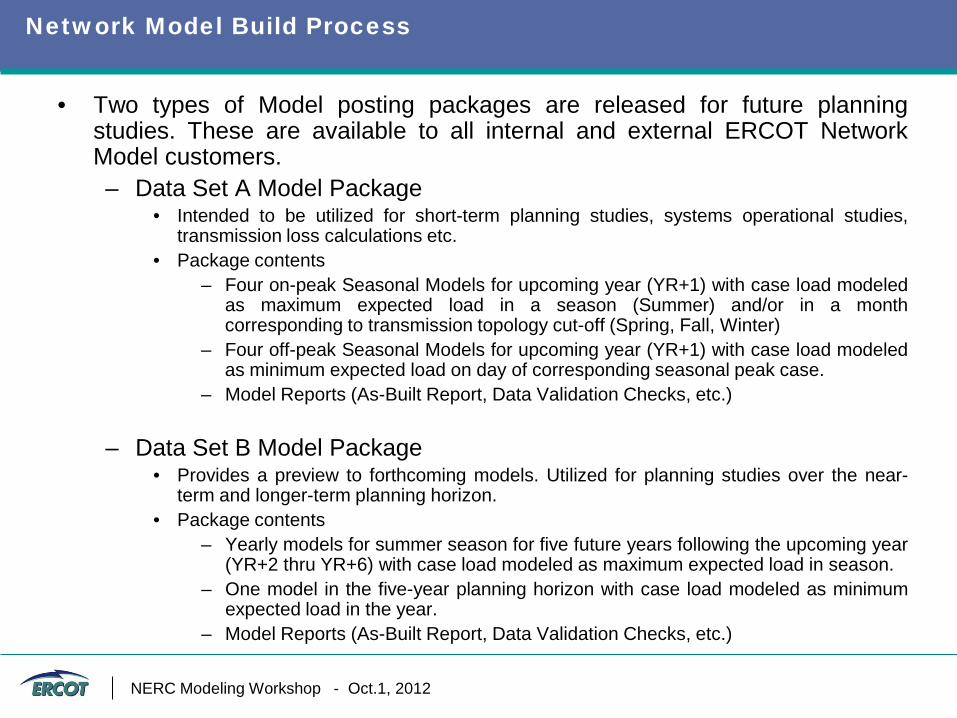
Network Model Build Process
• Two types of Model posting packages are released for future planning studies. These are available to all internal and external ERCOT Network Model customers. – Data Set A Model Package
• Intended to be utilized for short-term planning studies, systems operational studies, transmission loss calculations etc.
• Package contents – Four on-peak Seasonal Models for upcoming year (YR+1) with case load modeled
as maximum expected load in a season (Summer) and/or in a month corresponding to transmission topology cut-off (Spring, Fall, Winter)
– Four off-peak Seasonal Models for upcoming year (YR+1) with case load modeled as minimum expected load on day of corresponding seasonal peak case.
– Model Reports (As-Built Report, Data Validation Checks, etc.)
– Data Set B Model Package • Provides a preview to forthcoming models. Utilized for planning studies over the near-
term and longer-term planning horizon. • Package contents
– Yearly models for summer season for five future years following the upcoming year (YR+2 thru YR+6) with case load modeled as maximum expected load in season.
– One model in the five-year planning horizon with case load modeled as minimum expected load in the year.
– Model Reports (As-Built Report, Data Validation Checks, etc.)
NERC Modeling Workshop - Oct.1, 2012
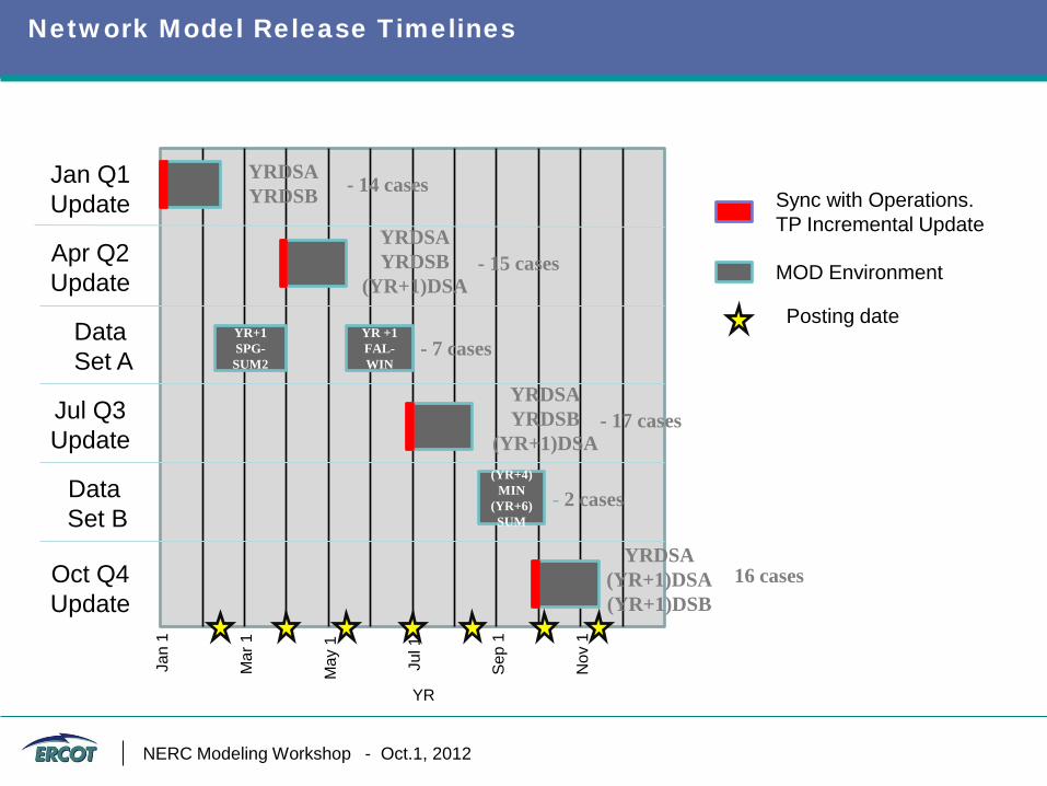
Network Model Release Timelines
Jan
1 Jan Q1 Update
Apr Q2 Update
Data Set A
Jul Q3 Update
Oct Q4 Update
Data Set B
YRDSA YRDSB - 14 cases
YR+1 SPG-SUM2
Mar
1
May
1
Jul 1
Sep
1
Nov
1
YRDSA YRDSB
(YR+1)DSA - 15 cases
YR +1 FAL-WIN
- 7 cases
YRDSA YRDSB
(YR+1)DSA - 17 cases
(YR+4)MIN
(YR+6) SUM
- 2 cases
YRDSA (YR+1)DSA (YR+1)DSB
16 cases
MOD Environment
Posting date
Sync with Operations. TP Incremental Update
YR
NERC Modeling Workshop - Oct.1, 2012
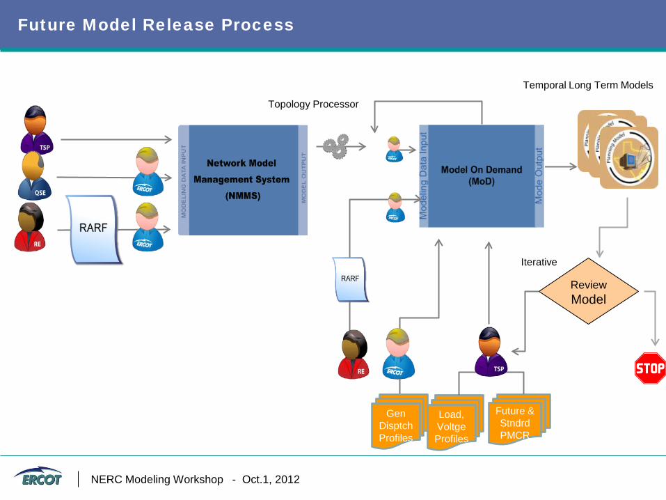
Future Model Release Process
Temporal Long Term Models
Review Model
Iterative
Load, Voltge Profiles
Future & Stndrd PMCR
Gen Disptch Profiles
Topology Processor
NERC Modeling Workshop - Oct.1, 2012
Building Network Models for Operations & Market
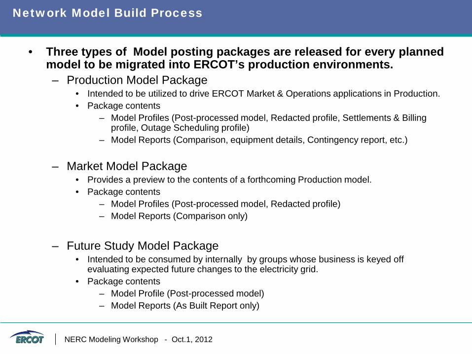
Network Model Build Process
• Three types of Model posting packages are released for every planned model to be migrated into ERCOT’s production environments. – Production Model Package
• Intended to be utilized to drive ERCOT Market & Operations applications in Production. • Package contents
– Model Profiles (Post-processed model, Redacted profile, Settlements & Billing profile, Outage Scheduling profile)
– Model Reports (Comparison, equipment details, Contingency report, etc.)
– Market Model Package • Provides a preview to the contents of a forthcoming Production model. • Package contents
– Model Profiles (Post-processed model, Redacted profile) – Model Reports (Comparison only)
– Future Study Model Package
• Intended to be consumed by internally by groups whose business is keyed off evaluating expected future changes to the electricity grid.
• Package contents – Model Profile (Post-processed model) – Model Reports (As Built Report only)
NERC Modeling Workshop - Oct.1, 2012
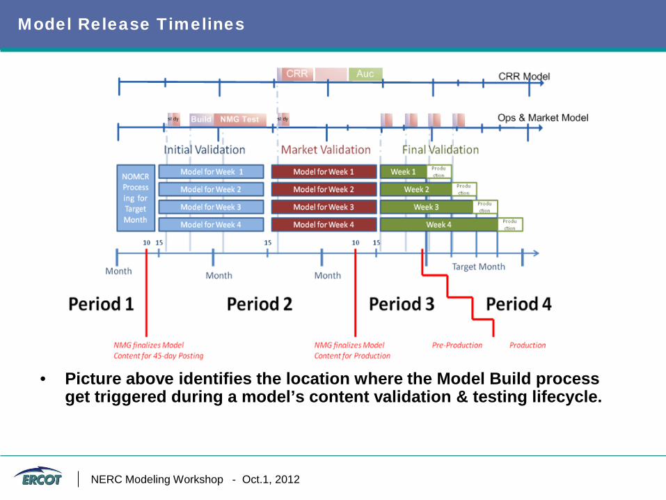
Model Release Timelines
• Picture above identifies the location where the Model Build process get triggered during a model’s content validation & testing lifecycle.
NERC Modeling Workshop - Oct.1, 2012
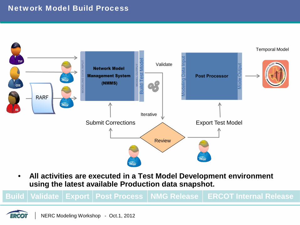
Network Model Build Process
Build Validate Export Post Process NMG Release ERCOT Internal Release
Temporal Model
Validate
Review
Iterative
Submit Corrections Export Test Model
Bui
ld T
est M
odel
• All activities are executed in a Test Model Development environment
using the latest available Production data snapshot.
NERC Modeling Workshop - Oct.1, 2012

NMMS Development
Questions?
Nitika Mago, P.E. Network Model Engineer
Network Model Administration [email protected]
512-248-6601
NERC MVWG Proposal for Node-breaker Modeling Eric H. Allen
October 1, 2012
2
RELIABILITY | ACCOUNTABILITY
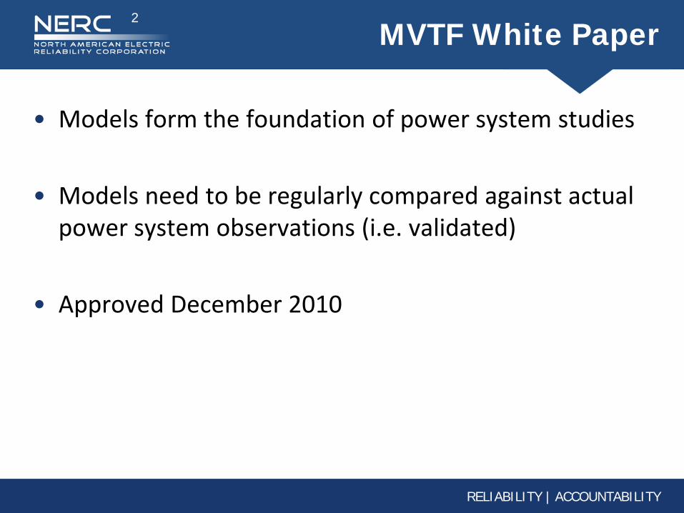
MVTF White Paper
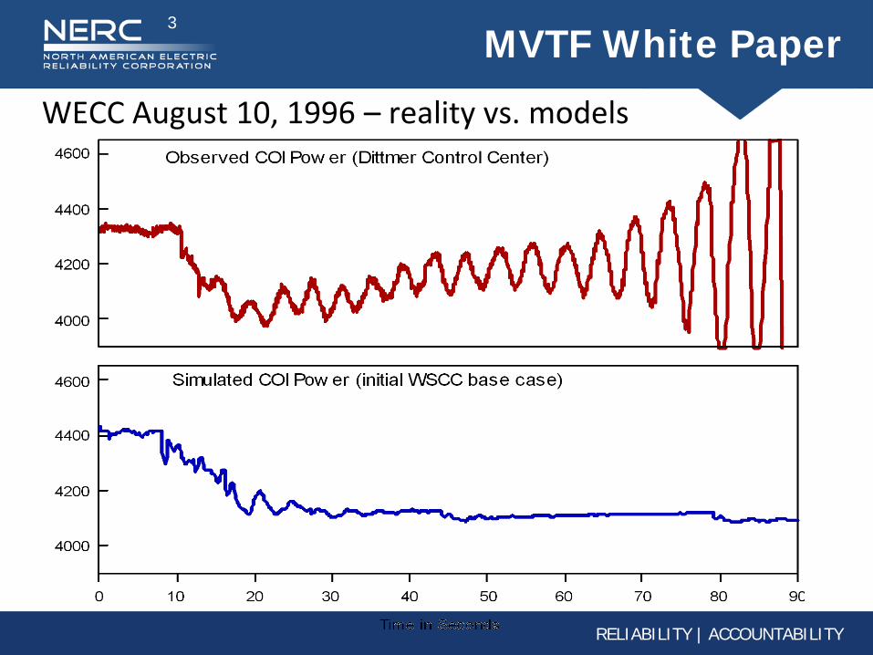
• Models form the foundation of power system studies
• Models need to be regularly compared against actual power system observations (i.e. validated)
• Approved December 2010
3
RELIABILITY | ACCOUNTABILITY
MVTF White Paper
WECC August 10, 1996 – reality vs. models
4
RELIABILITY | ACCOUNTABILITY
MVTF White Paper
• NERC Recommendation 14 from August 14, 2003 “The regional reliability councils shall within one year
establish and begin implementing criteria and procedures for validating data used in power flow models and dynamics simulations by benchmarking model data with actual system performance. Validated modeling data shall be exchanged on an inter-regional basis as needed for reliable system planning and operation.”
5
RELIABILITY | ACCOUNTABILITY
Recommendations
• 1. Periodic model validation should be an integral part of model maintenance
• 2. Operational planning (offline) models should be periodically validated by comparison with models from real-time systems. “Node-breaker” models
Standardized data transfer format
Universal identification of equipment
6
RELIABILITY | ACCOUNTABILITY
MVTF/MVWG Work Plan
• Task 2.2: The MVTF should draft a proposal for the Industry to institute node-breaker models in all off-line study models
7
RELIABILITY | ACCOUNTABILITY
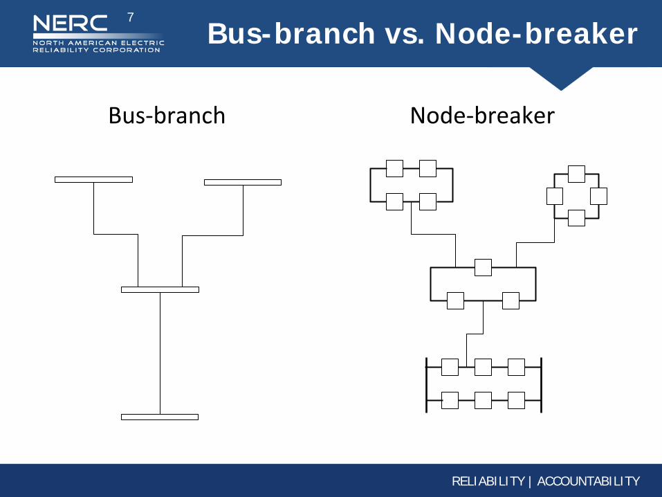
Bus-branch vs. Node-breaker
Bus-branch Node-breaker
8
RELIABILITY | ACCOUNTABILITY
Benefits of Node-breaker
• Much better alignment with real-time models Greatly improved construction of historic powerflow cases
Real-time and off-line models can be constructed from the same database
• Greatly enhanced contingency evaluation Have computers identify breakers needed to isolate faults
and elements that trip in common
Stuck breaker contingency evaluation
Elimination of error-prone process of manually maintaining contingency decks
New TPL-001 standard
9
RELIABILITY | ACCOUNTABILITY
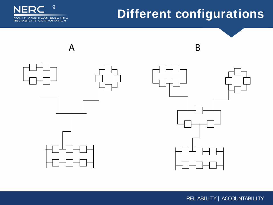
Different configurations
A B
10
RELIABILITY | ACCOUNTABILITY
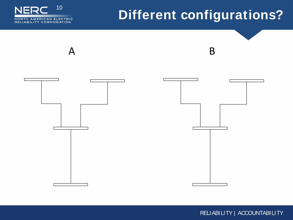
Different configurations?
A B
11
RELIABILITY | ACCOUNTABILITY
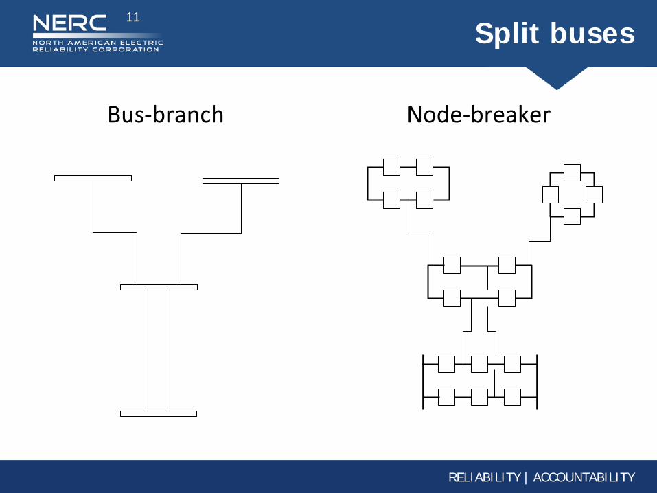
Split buses
Bus-branch Node-breaker
12
RELIABILITY | ACCOUNTABILITY
Hurdles to Node-breaker
• Significant additional data Handling large interconnection powerflow cases
• Lack of familiarity in off-line study environments
• Transition costs
13
RELIABILITY | ACCOUNTABILITY
State of Node-breaker
• Being implemented by powerflow software vendors
• Computation time needed for additional topological processing is not significant, according to vendors
Interconnection-Wide Studies Goals and Studies
NERC Modeling Workshop – Bloomington, MN October 1-3, 2012
2 RELIABILITY | ACCOUNTABILITY
Forensic Analysis
1. Sequence of event analysis
2. Powerflow analysis
3. Dynamic Analysis a. May utilize all three time frames – transient, mid-term,
and long-term
4. Verification of protection operations
3 RELIABILITY | ACCOUNTABILITY
Transient Timeframe (< 20 sec)
1. Frequency response analysis a. UFLS system design
b. System separation studies – Frequency Response and under-frequency load shedding requirements. Includes study of restoration.
c. Resource mix change
2. Sensitivity Studies (including extreme contingency analysis – do an extreme contingencies spill over into other areas of an interconnection?) Includes study of system restoration.
4 RELIABILITY | ACCOUNTABILITY
Transient Timeframe (< 20 sec)
3. Inter-area oscillations (small-signal stability) Sensitivity Studies (including extreme contingency analysis – do an extreme contingencies spill over into other areas of an interconnection?) Includes study of system restoration. a. Mode shape determination – Eigenvalue analysis
b. Challenging with user/proprietary models which do not translate into small signal study
5 RELIABILITY | ACCOUNTABILITY
Transient Timeframe (< 20 sec)
4. Forensic analysis of disturbances a. ERCOT – ??
b. Western Interconnection – 2 to 3 weeks to develop
c. Eastern Interconnection – 4 to 6 months to develop
5. Inter-area transfer capabilities a. Regional and Interregional studies
6. GMD powerflow analysis – New developments
7. Reserve Assessments & deliverability a. Combination of capacity and deliverability analysis coming
6 RELIABILITY | ACCOUNTABILITY
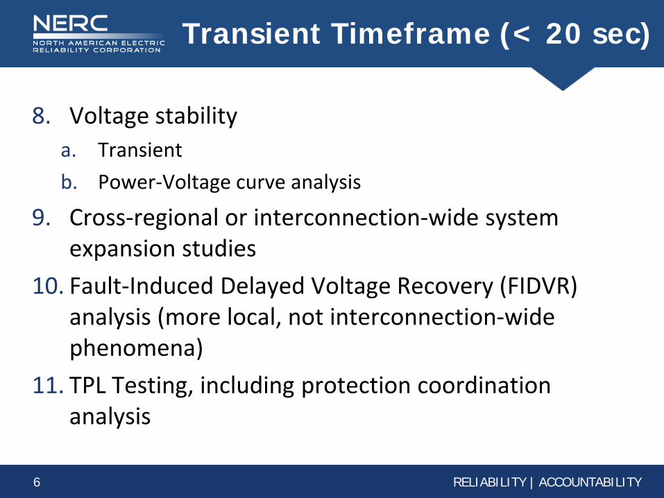
Transient Timeframe (< 20 sec)
8. Voltage stability a. Transient
b. Power-Voltage curve analysis
9. Cross-regional or interconnection-wide system expansion studies
10. Fault-Induced Delayed Voltage Recovery (FIDVR) analysis (more local, not interconnection-wide phenomena)
11. TPL Testing, including protection coordination analysis
7 RELIABILITY | ACCOUNTABILITY
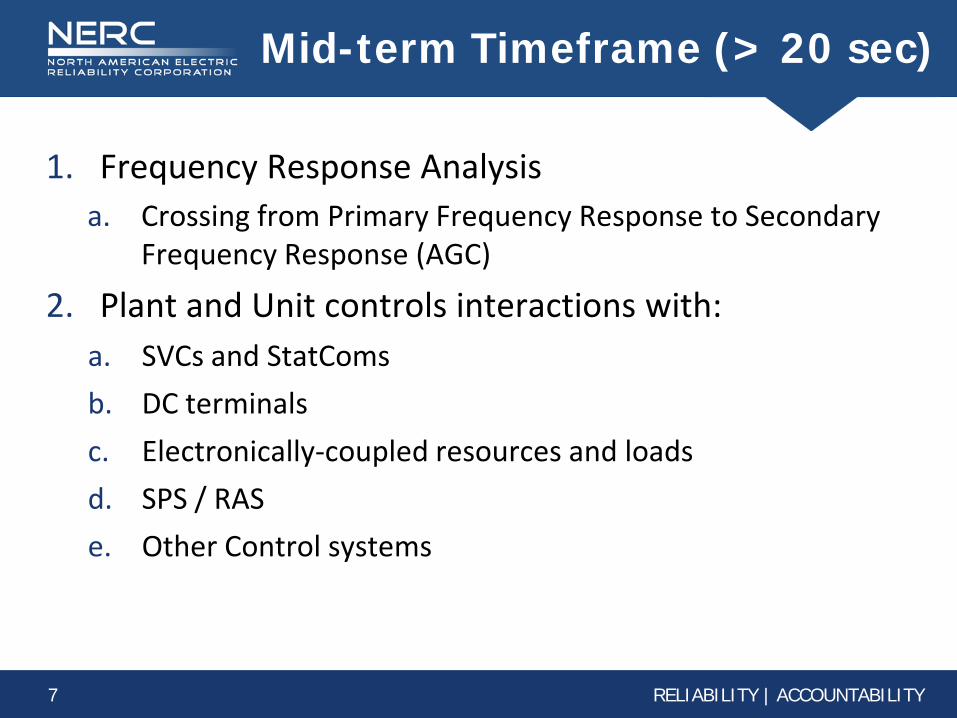
Mid-term Timeframe (> 20 sec)
1. Frequency Response Analysis a. Crossing from Primary Frequency Response to Secondary
Frequency Response (AGC)
2. Plant and Unit controls interactions with: a. SVCs and StatComs
b. DC terminals
c. Electronically-coupled resources and loads
d. SPS / RAS
e. Other Control systems
8 RELIABILITY | ACCOUNTABILITY
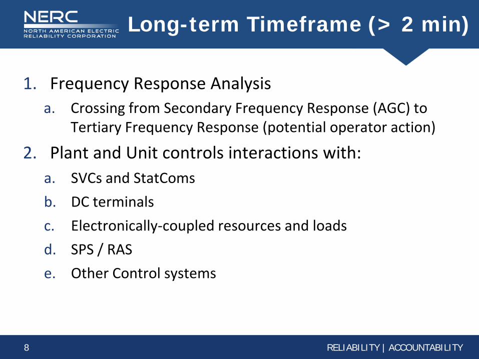
Long-term Timeframe (> 2 min)
1. Frequency Response Analysis a. Crossing from Secondary Frequency Response (AGC) to
Tertiary Frequency Response (potential operator action)
2. Plant and Unit controls interactions with: a. SVCs and StatComs
b. DC terminals
c. Electronically-coupled resources and loads
d. SPS / RAS
e. Other Control systems
9 RELIABILITY | ACCOUNTABILITY
Questions?
1529pk - 1
Power System Stability Overview
presented by:
Prabha S. Kundur Kundur Power Systems Solutions, Inc.
Toronto, Ontario
NERC Modeling Workshop October 1-3, 2012
Copyright © P. Kundur This material should not be used without the author's consent
1529pk - 2 Copyright © P. Kundur
Power System Stability Overview
Outline
1. Brief Introduction to Power System Stability Basic concepts Classification Description of different categories of stability
2. Impact of new forms of generation: WTGs and PVs
3. Modeling requirements for each category of stability
4. Overall approach to model identification and validation
5. Where are the significant gaps?
1529pk - 3 Copyright © P. Kundur
Power System Stability
Refers to continuance of intact operation of power system, following a disturbance
Recognized as an important problem for secure system operation since the 1920s
Major concern since the infamous November 9, 1965 blackout of Northeast US and Ontario criteria and analytical tools used until recently largely based on the
developments that followed
Presents many new challenges for today's power systems
1529pk - 4 Copyright © P. Kundur
Power System Stability: Definition
Power System Stability denotes the ability of an electric power system, for a given initial operating condition, to regain a state of operating equilibrium after being subjected to a physical disturbance, with all system variables bounded so that the system integrity is preserved integrity of the system is preserved when practically the entire power
system remains intact with no undue tripping of generators or loads
Stability is a condition of equilibrium between opposing forces: instability results when a disturbance leads to a sustained imbalance
between the opposing forces
Ref: IEEE/CIGRE TF Report, "Definition and Classification of Power System Stability", IEEE Trans. on Power Systems, Vol. 19, pp. 1387-1401, August 2004
1529pk - 5 Copyright © P. Kundur
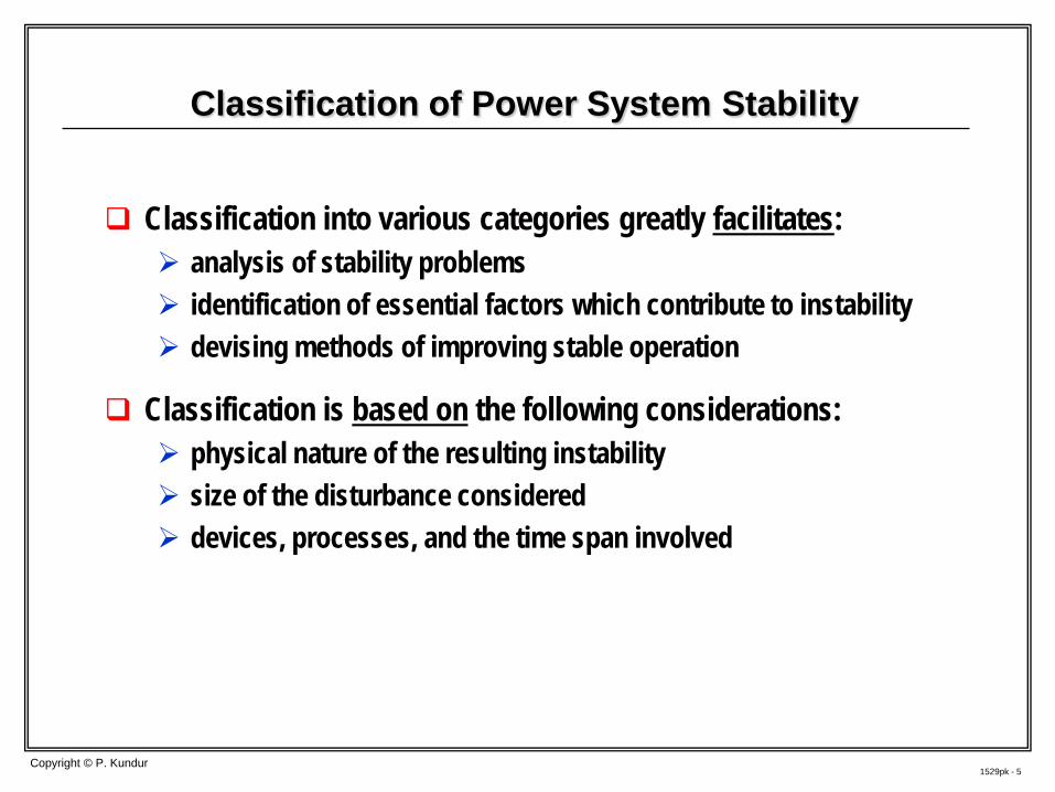
Classification of Power System Stability
Classification into various categories greatly facilitates: analysis of stability problems identification of essential factors which contribute to instability devising methods of improving stable operation
Classification is based on the following considerations: physical nature of the resulting instability size of the disturbance considered devices, processes, and the time span involved
1529pk - 6 Copyright © P. Kundur
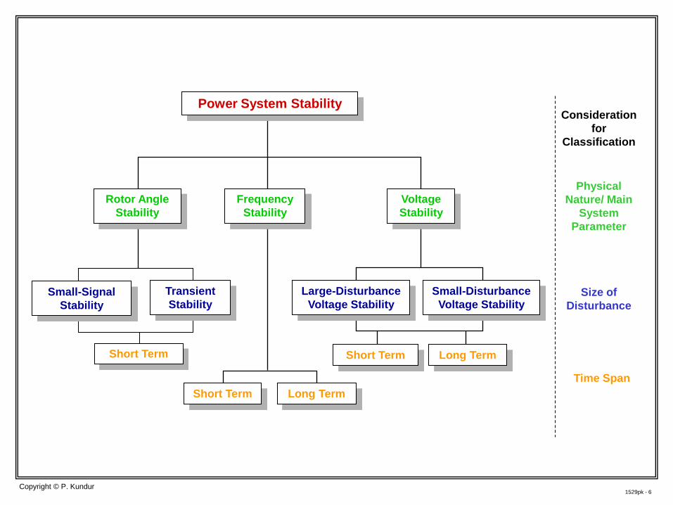
Power System Stability
Frequency Stability
Small-Signal Stability
Transient Stability
Short Term Long Term
Large-Disturbance Voltage Stability
Small-Disturbance Voltage Stability
Voltage Stability
Rotor Angle Stability
Consideration for
Classification
Physical Nature/ Main
System Parameter
Size of Disturbance
Time Span
Short Term
Short Term Long Term
1529pk - 7 Copyright © P. Kundur
Rotor Angle Stability
Ability of interconnected synchronous machines to remain in synchronism after being subjected to a disturbance
Depends on the ability to restore equilibrium between electromagnetic torque and mechanical torque of each synchronous machine
If the generators become unstable when perturbed, it is as a result of a run-away situation due to torque imbalance
A fundamental factor is the manner in which power outputs of synchronous machines vary as their rotor angles swing
Instability that may result occurs in the form of increasing angular swings of some generators leading to loss of synchronism with other generators
1529pk - 8 Copyright © P. Kundur
Transient Stability
Term traditionally used to denote large-disturbance angle stability
Ability of a power system to maintain synchronism when subjected to a severe transient disturbance: influenced by the nonlinear power-angle relationship
stability depends on the initial operating condition and severity of the disturbance
A wide variety of disturbances can occur on the system
The system is, however, designed and operated so as to be stable for a selected set of contingencies usually, transmission faults
N-1 criterion
1529pk - 9 Copyright © P. Kundur
Small-Signal (Angle) Stability
Small-Signal (or Small-Disturbance) Stability is the ability of a power system to maintain synchronism under small disturbances disturbance considered sufficiently small if linearization of system
equations is permissible for analysis Instability that may result can be of two forms:
aperidic increase in rotor angle due to lack of sufficient synchronizing torque
rotor oscillations of increasing amplitude due to lack of sufficient damping torque
In today's practical power systems, SSS problems are usually associated with oscillatory modes local plant mode oscillations: 0.8 to 2.0 Hz interarea oscillations: 0.1 to 0.8 Hz
1529pk - 10 Copyright © P. Kundur
Voltage Stability
Ability of power system to maintain steady voltages at all buses in the system after being subjected to a disturbance
A system experiences voltage instability when a disturbance, increase in load demand, or change in system condition causes: a progressive and uncontrollable fall or rise in voltage of buses
in a small area or a relatively large area Main factor causing voltage instability is the inability of power system to
maintain a proper balance of reactive power and voltage control actions
The driving force for voltage instability is usually the load characteristics
1529pk - 11 Copyright © P. Kundur
Short-Term and Long-Term Voltage Stability
Short-term voltage stability involves dynamics of fast acting load components such as induction motors, electronically controlled loads and HVDC converters study period of interest is in the order of a seconds dynamic modeling of loads essential; analysis requires solution of
differential equations using time-domain simulations faults/short-circuits near loads could be important
Long-term voltage stability involves slower acting equipment such as tap-changing transformers, thermostatically controlled loads, and generator field current (over excitation) limiters study period may extend to several minutes
1529pk - 12 Copyright © P. Kundur
Frequency Stability
Ability to maintain steady frequency within a nominal range following a disturbance resulting in a significant imbalance between total area generation and load
Instability that may result occurs in the form of sustained frequency swings leading to tripping of generating units and/or loads
In a small "island" system, frequency stability could be of concern for any disturbance causing a significant loss of load or generation
1529pk - 13 Copyright © P. Kundur
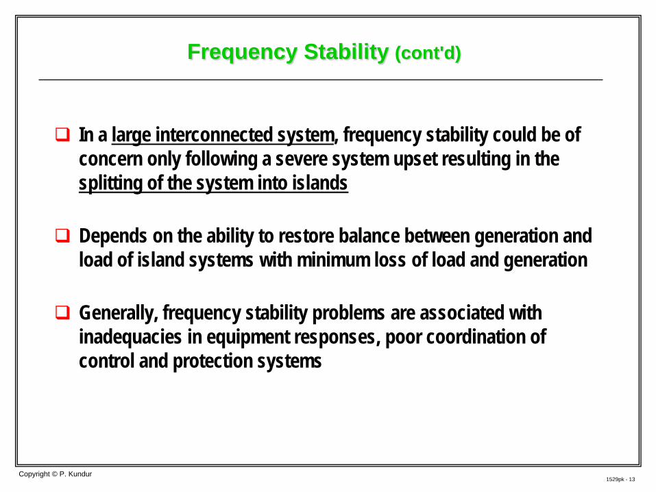
Frequency Stability (cont'd)
In a large interconnected system, frequency stability could be of concern only following a severe system upset resulting in the splitting of the system into islands
Depends on the ability to restore balance between generation and load of island systems with minimum loss of load and generation
Generally, frequency stability problems are associated with inadequacies in equipment responses, poor coordination of control and protection systems
1529pk - 14 Copyright © P. Kundur
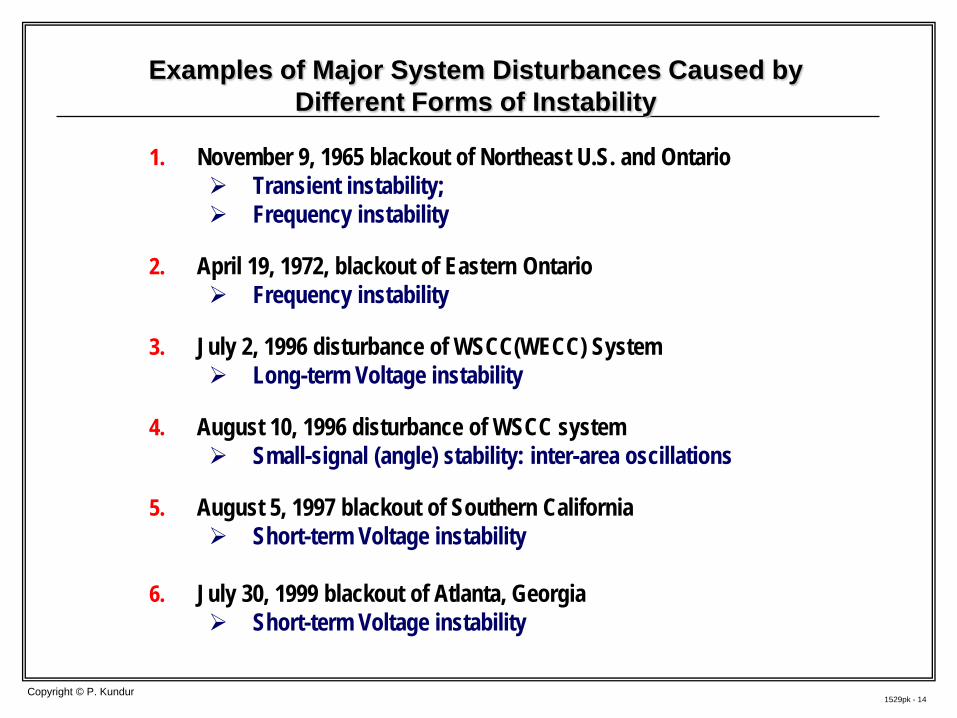
Examples of Major System Disturbances Caused by Different Forms of Instability
1. November 9, 1965 blackout of Northeast U.S. and Ontario Transient instability; Frequency instability
2. April 19, 1972, blackout of Eastern Ontario
Frequency instability
3. July 2, 1996 disturbance of WSCC(WECC) System Long-term Voltage instability
4. August 10, 1996 disturbance of WSCC system
Small-signal (angle) stability: inter-area oscillations
5. August 5, 1997 blackout of Southern California Short-term Voltage instability
6. July 30, 1999 blackout of Atlanta, Georgia Short-term Voltage instability
1529pk - 15
Impact of New Forms Generation: WTGs and PVs
Copyright © P. Kundur
1529pk - 16 Copyright © P. Kundur
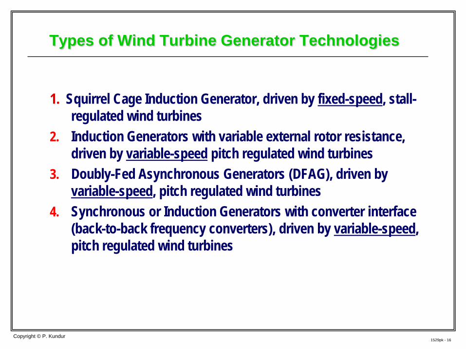
Types of Wind Turbine Generator Technologies
1. Squirrel Cage Induction Generator, driven by fixed-speed, stall-regulated wind turbines
2. Induction Generators with variable external rotor resistance, driven by variable-speed pitch regulated wind turbines
3. Doubly-Fed Asynchronous Generators (DFAG), driven by variable-speed, pitch regulated wind turbines
4. Synchronous or Induction Generators with converter interface (back-to-back frequency converters), driven by variable-speed, pitch regulated wind turbines
1529pk - 17 Copyright © P. Kundur
Impact of Wind Power Plants on System Dynamics
Could have a significant impact on Voltage Stability Induction generators absorb high reactive power when voltage is low DFAG may “crow-bar” during a system fault, and act as an induction
generator A short-term phenomenon Overall solution requires coordinated voltage control of wind power
plants, including use of SVCs and STATCOMs
Type 3 and 4 WTGS do not contribute system inertia May contribute to Frequency Instability Result in higher rate of change of frequency
Detailed simulation studies using appropriate models essential for satisfactory integration of large wind power plants
1529pk - 18 Copyright © P. Kundur
Capabilities of Modern WTGS
With the significant growth in wind power, wind power plants will be required to perform like conventional power plants
Modern WTGs, based on Type 3 and 4 technologies, can contribute to reliability and efficiency of grid operation by offering the following capabilities: Voltage and VAr control Real power control, ramping and curtailment Primary frequency regulation Inertia response: special control
1529pk - 19 Copyright © P. Kundur
Modeling of Wind Power Plants
For system studies aggregated representation is sufficient Single WTG model to represent the wind farm or a sub-group of WTGs
Detailed models for WTGs developed by manufacturers and consultants for grid integration studies and design of WPPs are considered as Proprietary user-defined models
Further, maintenance of numerous vendor-specific models is unmanageable
Efforts are underway for developing “Generic” WTG models suitable for “system impact” studies
1529pk - 20 Copyright © P. Kundur
Solar Photo Voltaic Plants
Consist of multiple small sources of power, which are aggregated and injected into the transmission system at a single point Use converter interface to the power grid
Modern units have capability for reactive power control, voltage regulation and under-voltage tripping
Technical issues related to impact on power system performance
similar to those for Type 4 WTGs Voltage stability, frequency stability, and rate of change of frequency
may be issues that have to be addressed Units with constant power factor control may contribute to voltage
control problems
1529pk - 21
Modeling Requirements for Each Category of System Stability
Copyright © P. Kundur
1529pk - 22 Copyright © P. Kundur
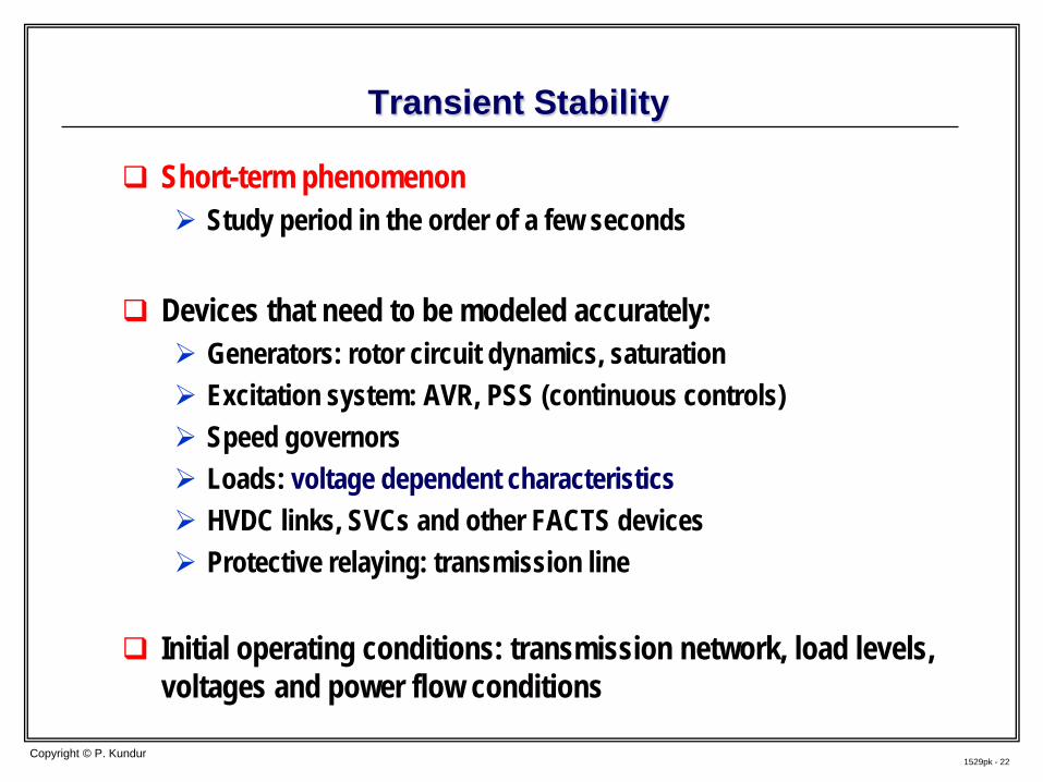
Transient Stability
Short-term phenomenon Study period in the order of a few seconds
Devices that need to be modeled accurately:
Generators: rotor circuit dynamics, saturation Excitation system: AVR, PSS (continuous controls) Speed governors Loads: voltage dependent characteristics HVDC links, SVCs and other FACTS devices Protective relaying: transmission line
Initial operating conditions: transmission network, load levels, voltages and power flow conditions
1529pk - 23 Copyright © P. Kundur
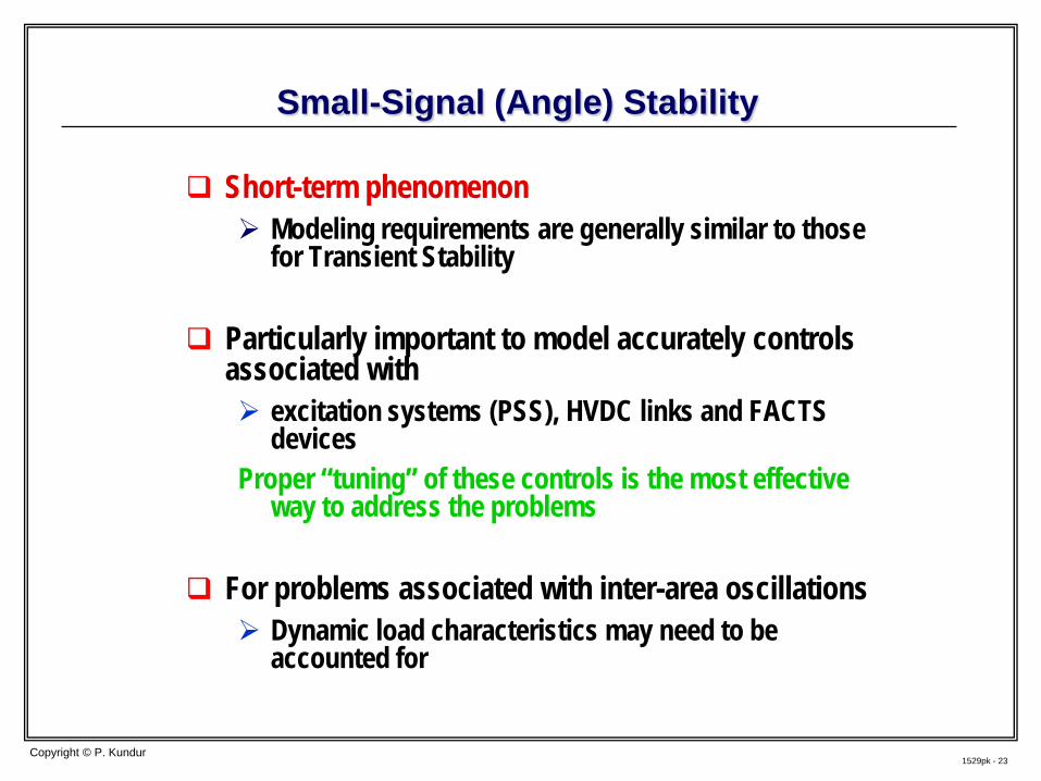
Small-Signal (Angle) Stability
Short-term phenomenon Modeling requirements are generally similar to those
for Transient Stability
Particularly important to model accurately controls associated with excitation systems (PSS), HVDC links and FACTS
devices Proper “tuning” of these controls is the most effective
way to address the problems
For problems associated with inter-area oscillations Dynamic load characteristics may need to be
accounted for
1529pk - 24 Copyright © P. Kundur
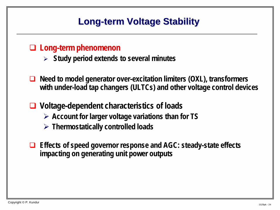
Long-term Voltage Stability
Long-term phenomenon Study period extends to several minutes
Need to model generator over-excitation limiters (OXL), transformers
with under-load tap changers (ULTCs) and other voltage control devices
Voltage-dependent characteristics of loads Account for larger voltage variations than for TS Thermostatically controlled loads
Effects of speed governor response and AGC: steady-state effects
impacting on generating unit power outputs
1529pk - 25 Copyright © P. Kundur
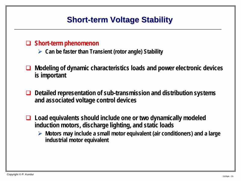
Short-term Voltage Stability
Short-term phenomenon Can be faster than Transient (rotor angle) Stability
Modeling of dynamic characteristics loads and power electronic devices is important
Detailed representation of sub-transmission and distribution systems
and associated voltage control devices Load equivalents should include one or two dynamically modeled
induction motors, discharge lighting, and static loads Motors may include a small motor equivalent (air conditioners) and a large
industrial motor equivalent
1529pk - 26 Copyright © P. Kundur
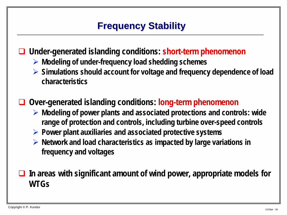
Frequency Stability
Under-generated islanding conditions: short-term phenomenon Modeling of under-frequency load shedding schemes Simulations should account for voltage and frequency dependence of load
characteristics
Over-generated islanding conditions: long-term phenomenon Modeling of power plants and associated protections and controls: wide
range of protection and controls, including turbine over-speed controls Power plant auxiliaries and associated protective systems Network and load characteristics as impacted by large variations in
frequency and voltages In areas with significant amount of wind power, appropriate models for
WTGs
1529pk - 27
Overall Approach to Model Identification and Validation
Copyright © P. Kundur
1529pk - 28 Copyright © P. Kundur
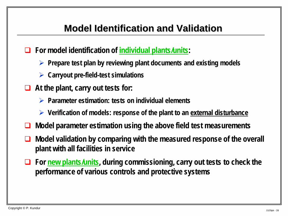
Model Identification and Validation
For model identification of individual plants/units: Prepare test plan by reviewing plant documents and existing models Carryout pre-field-test simulations
At the plant, carry out tests for: Parameter estimation: tests on individual elements Verification of models: response of the plant to an external disturbance
Model parameter estimation using the above field test measurements Model validation by comparing with the measured response of the overall
plant with all facilities in service For new plants/units, during commissioning, carry out tests to check the
performance of various controls and protective systems
1529pk - 29 Copyright © P. Kundur
Validation Integrated Power System Model
Dynamic models of the overall power system are very complex Involve a complex array of devices and associated controls and
protective systems
Verification of the integrated power system model by comparing with the measured responses during system disturbances Based on accurate time synchronized PMU records (WAMS)
Reflect on the accuracy of models of elements having a
significant impact on the particular system disturbance Device models and parameters responsible for any discrepancies

1529pk - 30
Where are the significant gaps?
Copyright © P. Kundur
1529pk - 31 Copyright © P. Kundur
Significant Gaps in Power System Modeling
Models for loads: Dynamic characteristics of composite loads Impact of variations in load composition with time of the day,
weather conditions and state of the economy Models for limiters and protective functions associated with
generator excitation system: Over-excitation limiter (OXL), under-excitation limiter (UEL),
V/Hz limiter and protection Protective system settings and their coordination
Settings for protective systems associated with various elements of the transmission and distribution network
Coordination of various protective relays Coordination with emergency ratings of equipment to ensure
sufficient margin
1529pk - 32 Copyright © P. Kundur
Significant Gaps in Modeling (contd.)
EMS and State Estimator results of system and network operating conditions Measurement errors; errors due to analytical techniques used Measurement errors mostly associated with data from substation
instrument transformers Solution is to use advanced EMS using Synchrophasor Data based on
phasor measurement units (PMUs)
Representation of neighboring (external) systems
Status of transmission facilities and operating conditions
Lack of adequate real-time “Situation Awareness” and “Shared Decision Making” t'd
Recommended