Using the Ducted Gas Central Heating
Add-on Refrigerated Air Conditioning
Ducted Evaporative Air Conditioning
with your
multi-appliance
Manual Control
Owner’s Manual
Please keep this important manual in a safe place. It is the owner’s responsibility to ensure that regular maintenance is carried out on this ducted heating / cooling product. Failure to do so will void all guarantees beyond statutory and legal requirements.
www.climatetechnologies.com.au
PNE2003 Series Control
Multi-Appliance Manual Control
Contents
Contents
INTRODUCTION...................................................................................................5 YOUR MANUAL CONTROLLER .................................................................................................................5 GENERAL INFORMATION..........................................................................................................................6
Important Installation Notice. .................................................................................................... 6 Data Location............................................................................................................................ 6 Warranty ................................................................................................................................... 6 Assembly. ................................................................................................................................. 6
Navigating the Controls......................................................................................7 QUICK START - SIMPLE MANUAL OPERATION.......................................................................................8 CONTROL FUNCTIONS..............................................................................................................................9
ON / OFF .................................................................................................................................. 9 MODE ....................................................................................................................................... 9 Icons........................................................................................................................................ 10 Child Lock ............................................................................................................................... 10 Reset....................................................................................................................................... 11 CLOCK Setup ......................................................................................................................... 11 Fault Codes............................................................................................................................. 11
Ducted Gas Central Heating.............................................................................12 SAFETY ..................................................................................................................................................... 13
Safety & Owner Responsibility ............................................................................................... 13 Precautions. ............................................................................................................................ 13 Features.................................................................................................................................. 13 Power or Gas interruption. ...................................................................................................... 13
USING YOUR MANUAL CONTROL WITH DUCTED GAS CENTRAL HEATING..................................... 14 Heating Operation................................................................................................................... 14 Summer Fan (Fan Only) ......................................................................................................... 15 Summer Shutdown (Optional) ............................................................................................... 16 First Startup Or Restart After Shutdown................................................................................. 16
HEATER MAINTENANCE ......................................................................................................................... 17 General Maintenance.............................................................................................................. 17 Scheduled Maintenance ......................................................................................................... 17
PROBLEM SOLVING................................................................................................................................. 18
ADD-ON Refrigerated Air Conditioning...........................................................19 GENERAL INFORMATION........................................................................................................................ 20
Important Notice...................................................................................................................... 20 Data Location.......................................................................................................................... 20 Assembly. ............................................................................................................................... 20
Bonaire Control Systems Page 2
Multi-Appliance Manual Control
Contents
Contents
SAFETY ..................................................................................................................................................... 20 Safety & Owner Responsibility ............................................................................................... 20 Precautions. ............................................................................................................................ 20 Features.................................................................................................................................. 20 Power interruption................................................................................................................... 20
USING YOUR CONTROL WITH DUAL CYCLE AIR CONDITIONING...................................................... 21 Operation ................................................................................................................................ 21 Fan Operation ......................................................................................................................... 22
Ducted Evaporative Air Conditioning..............................................................23 INTRODUCTION........................................................................................................................................ 24
Air Relief ................................................................................................................................. 24 Dialflo ...................................................................................................................................... 25 Optional Dump Valve.............................................................................................................. 25
OPERATING THE MANUAL CONTROL. .................................................................................................. 26 COOL Mode............................................................................................................................ 26 COOL FRESH AIR Mode........................................................................................................ 26 FRESH AIR Mode................................................................................................................... 27
DUCTED EVAPORATIVE AIR CONDITIONER MAINTENANCE.............................................................. 28 General. .................................................................................................................................. 28 Filter Pads............................................................................................................................... 28 Water Tank ............................................................................................................................. 28 Water Level / Float Valve........................................................................................................ 28 Motor and Fan......................................................................................................................... 29 Electrical ................................................................................................................................. 29 Bleed Off ................................................................................................................................. 29 Pump....................................................................................................................................... 29 Water Distribution ................................................................................................................... 29 No Seasonal Maintenance...................................................................................................... 29
TROUBLE SHOOTING GUIDE.................................................................................................................. 30
Control setup.....................................................................................................31 SETTING UP THE CONTROL - GENERAL............................................................................................... 31
Before Starting ........................................................................................................................ 31 Installation............................................................................................................................... 31
USING THE SETUP MODES .................................................................................................................... 32 Product Identification .............................................................................................................. 32
CODING..................................................................................................................................................... 32 Auto-Coding ............................................................................................................................ 32
Bonaire Control Systems Page 3
Multi-Appliance Manual Control
Contents
Contents
Manual Coding........................................................................................................................ 32 Important Notes ...................................................................................................................... 33 Calibrating the Thermostat. .................................................................................................... 33 Fault Codes Access ................................................................................................................ 33 View The Fault Codes............................................................................................................. 33
EVAPORATIVE AIR CONDITIONING SETUP .......................................................................................... 34 Setting the Fan Speed ............................................................................................................ 34
DUCTED GAS CENTRAL HEATING......................................................................................................... 35 Setting the Fan Speed ............................................................................................................ 35
COMMISSIONING CHECK LIST ............................................................................................................... 36 General ................................................................................................................................... 36 Unit - Ducted Evaporative Air Conditioner .............................................................................. 36 Unit – Ducted Heating............................................................................................................. 36 Unit – Dual Cycle Refrigerated Air Conditioning..................................................................... 37 Ductwork ................................................................................................................................. 37 Site .......................................................................................................................................... 37 Customer Hand Over .............................................................................................................. 37
Warranty.............................................................................................................38
SERVICE ............................................................................................................42
Bonaire Control Systems Page 4
Multi-Appliance Manual Control
Introduction
Introduction
INTRODUCTION
YOUR MANUAL CONTROLLER This technologically advanced controller comes with manual controls for cooling and thermostat controls for heating plus many other setup functions.
Your Manual Control has been designed to operate the following products:
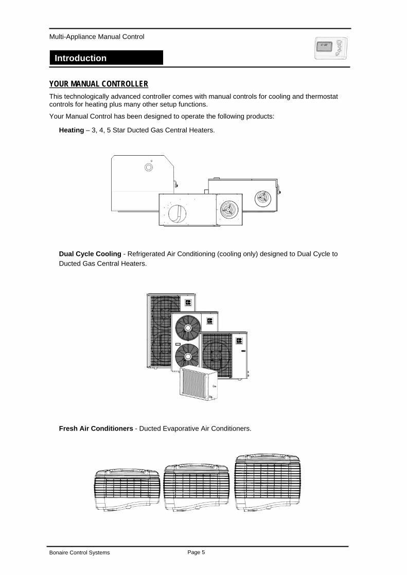
Heating – 3, 4, 5 Star Ducted Gas Central Heaters.
Dual Cycle Cooling - Refrigerated Air Conditioning (cooling only) designed to Dual Cycle to Ducted Gas Central Heaters.
Fresh Air Conditioners - Ducted Evaporative Air Conditioners.
Bonaire Control Systems Page 5
Multi-Appliance Manual Control
Introduction
Introduction
GENERAL INFORMATION. IMPORTANT INSTALLATION NOTICE. A licensed person is required to install Climate Technologies equipment. If the equipment is not installed in a accordance with the installation instructions and the governing body regulations, Climate Technologies reserves the right to refuse service on non compliant installations.
Subject to state regulations and by laws a certificate of compliance must be issued for the electrical and plumbing connections certifying that the work complies with all the relevant standards.
Note: Only a licensed person will have insurance protecting their workmanship.
DATA LOCATION. Your appliance model number, serial number and model description are located on the appliance data plate on the end of the heater or inside the cooler in the vicinity of the electronic controls. These details should also be in the warranty section of this booklet.
You will need this information, should your appliance require servicing, spare parts or just if you require additional information about this product.
WARRANTY Warranty service work must only be carried out by Climate Technologies service division or its authorised service providers. See warranty section.
ASSEMBLY. There is no assembly required of these Ducted Heating or Cooling products. Your Dealer or installer will carry out all assembly and commissioning upon installation.
Bonaire Control Systems Page 6
Multi-Appliance Manual Control
Navigating the Controls
Navigating the Controls
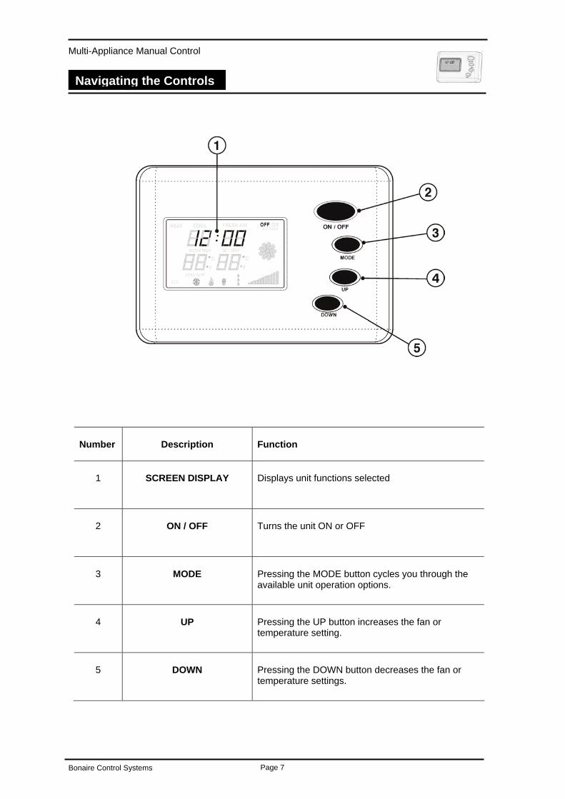
Navigating the Controls
Number Description Function
1 Displays unit functions selected SCREEN DISPLAY
2 Turns the unit ON or OFF ON / OFF
3 Pressing the MODE button cycles you through the available unit operation options.
MODE
4 Pressing the UP button increases the fan or temperature setting.
UP
5 Pressing the DOWN button decreases the fan or temperature settings.
DOWN
Bonaire Control Systems Page 7
Multi-Appliance Manual Control
Navigating the Controls
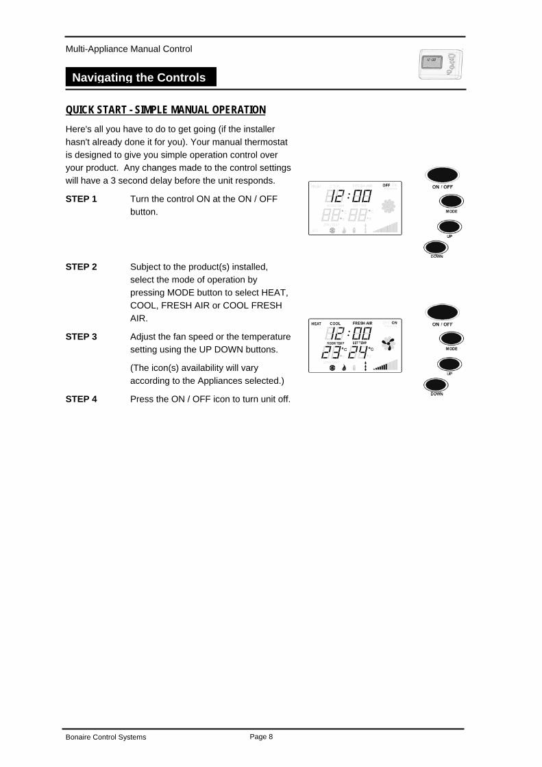
QUICK START - SIMPLE MANUAL OPERATION Here's all you have to do to get going (if the installer hasn't already done it for you). Your manual thermostat is designed to give you simple operation control over your product. Any changes made to the control settings will have a 3 second delay before the unit responds.
STEP 1 Turn the control ON at the ON / OFF button.
STEP 2 Subject to the product(s) installed, select the mode of operation by pressing MODE button to select HEAT, COOL, FRESH AIR or COOL FRESH AIR.
STEP 3 Adjust the fan speed or the temperature setting using the UP DOWN buttons.
(The icon(s) availability will vary according to the Appliances selected.)
STEP 4 Press the ON / OFF icon to turn unit off.
Bonaire Control Systems Page 8
Multi-Appliance Manual Control
Navigating the Controls
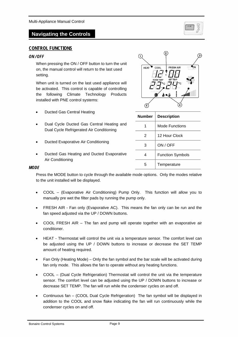
CONTROL FUNCTIONS ON / OFF
When pressing the ON / OFF button to turn the unit on, the manual control will return to the last used setting.
When unit is turned on the last used appliance will be activated. This control is capable of controlling the following Climate Technology Products installed with PNE control systems:
• Ducted Gas Central Heating Number Description
• Dual Cycle Ducted Gas Central Heating and Dual Cycle Refrigerated Air Conditioning
1 Mode Functions
2 12 Hour Clock • Ducted Evaporative Air Conditioning
3 ON / OFF
• Ducted Gas Heating and Ducted Evaporative Air Conditioning
4 Function Symbols
5 Temperature MODE
Press the MODE button to cycle through the available mode options. Only the modes relative to the unit installed will be displayed.
• COOL – (Evaporative Air Conditioning) Pump Only. This function will allow you to manually pre wet the filter pads by running the pump only.
• FRESH AIR - Fan only (Evaporative AC). This means the fan only can be run and the fan speed adjusted via the UP / DOWN buttons.
• COOL FRESH AIR – The fan and pump will operate together with an evaporative air conditioner.
• HEAT - Thermostat will control the unit via a temperature sensor. The comfort level can be adjusted using the UP / DOWN buttons to increase or decrease the SET TEMP amount of heating required.
• Fan Only (Heating Mode) – Only the fan symbol and the bar scale will be activated during fan only mode. This allows the fan to operate without any heating functions.
• COOL – (Dual Cycle Refrigeration) Thermostat will control the unit via the temperature sensor. The comfort level can be adjusted using the UP / DOWN buttons to increase or decrease SET TEMP. The fan will run while the condenser cycles on and off.
• Continuous fan – (COOL Dual Cycle Refrigeration) The fan symbol will be displayed in addition to the COOL and snow flake indicating the fan will run continuously while the condenser cycles on and off.
Bonaire Control Systems Page 9
Multi-Appliance Manual Control
Navigating the Controls
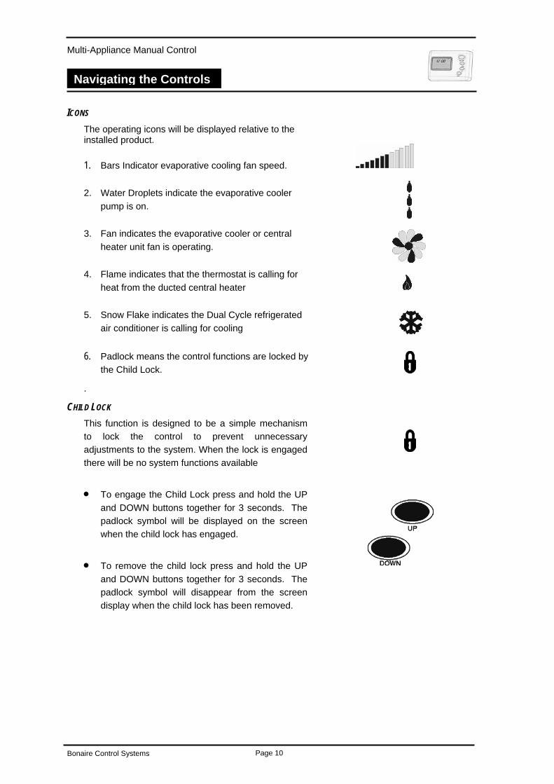
ICONS The operating icons will be displayed relative to the installed product.
1. Bars Indicator evaporative cooling fan speed.
2. Water Droplets indicate the evaporative cooler pump is on.
3. Fan indicates the evaporative cooler or central heater unit fan is operating.
4. Flame indicates that the thermostat is calling for heat from the ducted central heater
5. Snow Flake indicates the Dual Cycle refrigerated air conditioner is calling for cooling
6. Padlock means the control functions are locked by the Child Lock.
.
CHILD LOCK This function is designed to be a simple mechanism to lock the control to prevent unnecessary adjustments to the system. When the lock is engaged there will be no system functions available
•
•
To engage the Child Lock press and hold the UP and DOWN buttons together for 3 seconds. The padlock symbol will be displayed on the screen when the child lock has engaged.
To remove the child lock press and hold the UP and DOWN buttons together for 3 seconds. The padlock symbol will disappear from the screen display when the child lock has been removed.
Bonaire Control Systems Page 10
Multi-Appliance Manual Control
Navigating the Controls
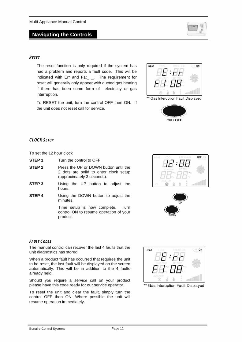
RESET
The reset function is only required if the system has had a problem and reports a fault code. This will be indicated with Err and F1:_ _. The requirement for reset will generally only appear with ducted gas heating if there has been some form of electricity or gas interruption.
To RESET the unit, turn the control OFF then ON. If the unit does not reset call for service.
CLOCK SETUP
To set the 12 hour clock
STEP 1 Turn the control to OFF
STEP 2 Press the UP or DOWN button until the 2 dots are solid to enter clock setup (approximately 3 seconds).
STEP 3 Using the UP button to adjust the hours.
STEP 4 Using the DOWN button to adjust the minutes.
Time setup is now complete. Turn control ON to resume operation of your product.
FAULT CODES The manual control can recover the last 4 faults that the unit diagnostics has stored.
When a product fault has occurred that requires the unit to be reset, the last fault will be displayed on the screen automatically. This will be in addition to the 4 faults already held.
Should you require a service call on your product please have this code ready for our service operator.
To reset the unit and clear the fault, simply turn the control OFF then ON. Where possible the unit will resume operation immediately.
Bonaire Control Systems Page 11
Multi-Appliance Manual Control
Ducted Gas Central Heating
Ducted Gas Central Heating
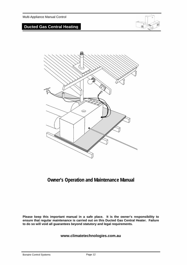
Owner’s Operation and Maintenance Manual
Please keep this important manual in a safe place. It is the owner’s responsibility to ensure that regular maintenance is carried out on this Ducted Gas Central Heater. Failure to do so will void all guarantees beyond statutory and legal requirements.
www.climatetechnologies.com.au
Bonaire Control Systems Page 12
Multi-Appliance Manual Control
Ducted Gas Central Heating
Congratulations on purchasing this ducted gas central heating system, an exciting new product manufactured by Climate Technologies.
Wholly designed and manufactured in Australia, this Ducted Gas Central Heater represents an exciting new development in warm air furnace design. It embodies the latest advances in gas heating technology.
Your heater is supported by Climate Technologies, Australia’s most advanced manufacturer of a complete range of climate control products.
To ensure you fully enjoy the benefits of this Ducted Gas Central Heater, please read these instructions carefully and keep them handy for future reference.
Operated and maintained in accordance with this manual, this unit will provide you with years of warm and environmentally friendly operation. Please take the time to read this manual.
SAFETY SAFETY & OWNER RESPONSIBILITY The manufacturer and its service providers reserve the right to refuse service unless safety and accessibility to the unit can be guaranteed. The cost of any extra equipment required to provide access to the unit for servicing is the responsibility of the owner.
PRECAUTIONS. DO NOT PLACE ARTICLES ON OR AGAINST THIS APPLIANCE.
DO NOT USE OR STORE FLAMMABLE MATERIALS NEAR THIS APPLIANCE.
DO NOT SPRAY AEROSOLS IN THE VICINITY OF THIS APPLIANCE WHILE IT IS IN OPERATION.
DO NOT PLACE ARTICLES IN FRONT OF OR OVER THE RETURN AIR GRILLE.
FEATURES. Your Ducted Gas Central Heater has all the safety devices to ensure safe operation. These devices conform to the standards set out by the Australian Gas Association.
POWER OR GAS INTERRUPTION. Should there be an interruption to the power supply during the heating operation the controls will automatically turn off the gas.
When the power is restored, the control will be in the OFF position and therefore will not resume operation until turned ON.
Should there be an interruption to the gas supply, the heater will endeavor to re-light 3 times and if unsuccessful will lock out. (This is part of the safety features). Should this occur the heater will need to be reset. If the Err is displayed, turn the control OFF then ON and the unit will be ready to resume operation.
Please refer to your problem-solving chart to assist resolving other problems.
Bonaire Control Systems Page 13
Multi-Appliance Manual Control
Ducted Gas Central Heating
USING YOUR MANUAL CONTROL WITH DUCTED GAS CENTRAL HEATING To operate your control simply press the ON / OFF button. The unit will then display the default or last used settings and will be ready to operate. Any changes made to the control settings will have a 3 second delay before the unit responds.
If the heater is connected in conjunction with an evaporative or Dual Cycle refrigerated air conditioner you may have to toggle through the modes to select the heating functions.
To select one of the modes below, simply push the MODE button until the screen displays the required settings. The following modes are available for the heater:
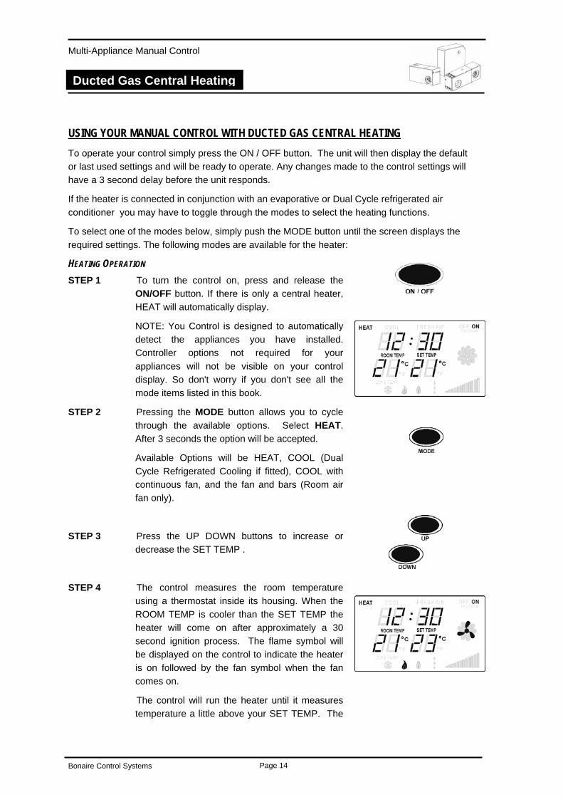
HEATING OPERATION STEP 1 To turn the control on, press and release the
ON/OFF button. If there is only a central heater, HEAT will automatically display.
NOTE: You Control is designed to automatically detect the appliances you have installed. Controller options not required for your appliances will not be visible on your control display. So don't worry if you don't see all the mode items listed in this book.
STEP 2 Pressing the MODE button allows you to cycle through the available options. Select HEAT. After 3 seconds the option will be accepted.
Available Options will be HEAT, COOL (Dual Cycle Refrigerated Cooling if fitted), COOL with continuous fan, and the fan and bars (Room air fan only).
STEP 3 Press the UP DOWN buttons to increase or decrease the SET TEMP .
STEP 4 The control measures the room temperature using a thermostat inside its housing. When the ROOM TEMP is cooler than the SET TEMP the heater will come on after approximately a 30 second ignition process. The flame symbol will be displayed on the control to indicate the heater is on followed by the fan symbol when the fan comes on.
The control will run the heater until it measures temperature a little above your SET TEMP. The
Bonaire Control Systems Page 14
Multi-Appliance Manual Control
Ducted Gas Central Heating
unit will turn off until the temperature falls a little below SET TEMP before restarting.
STEP 5 Press the ON/OFF button to switch the heater OFF.
STEP 6 The control remembers your SET TEMP setting and uses it next time you turn it ON.
The operation of the modulating heater is as follows:
• If at start up the temperature is 2.0° or more below the room temperature, the central heater will start up at high fan speed and high gas rate quickly bringing your house up to temperature.
• As the room temperature gets closer to the SET TEMP the central heater will reduce the room air fan and the gas rate to the burner.
• When the thermostat reaches the SET TEMP the central heater will be on low fan and the gas will modulate to low fire.
• When the temperature has gone over the SET TEMP by approximately 0.5° the central heater will shut down.
• When the temperature has dropped to approximately 1° below SET TEMP the unit will restart.
• As your activities vary, you may find you need different temperature settings, e.g. a temperature comfortable for sitting is usually too warm compared to when your moving about.
• For economical operation, set a low SET TEMP during the day when you are active. Switch the control OFF when asleep and ON again when awake.
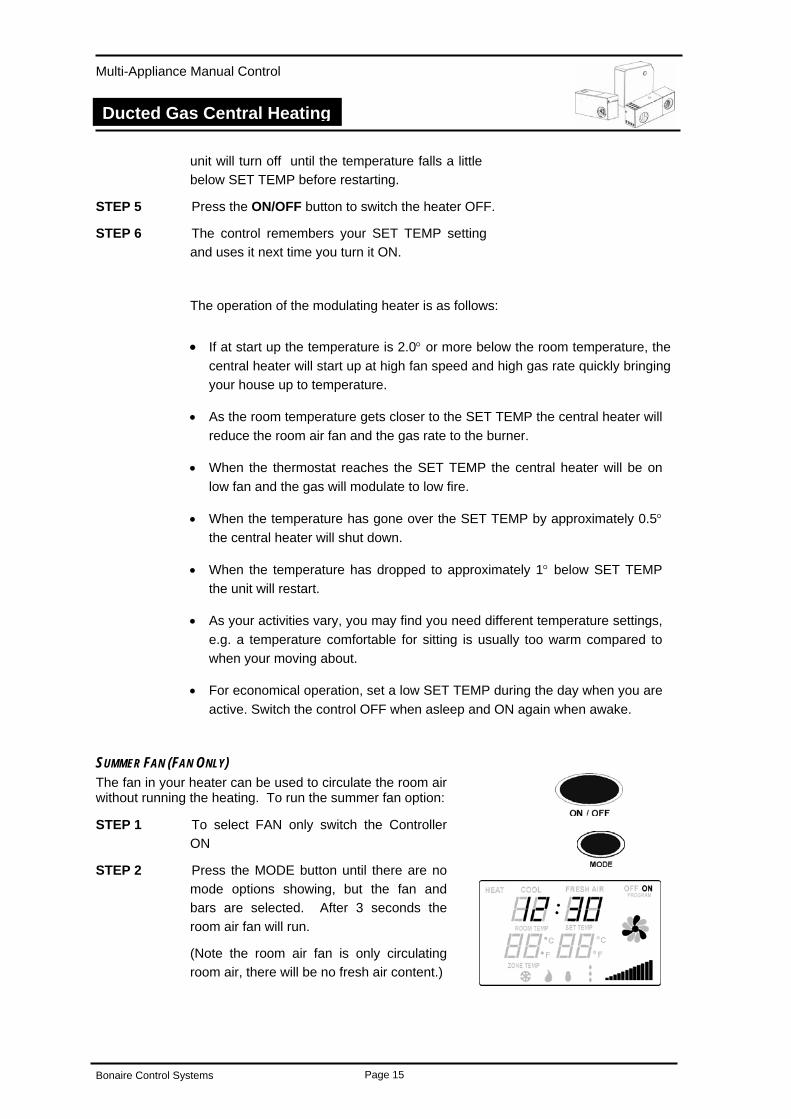
SUMMER FAN (FAN ONLY) The fan in your heater can be used to circulate the room air without running the heating. To run the summer fan option:
STEP 1 To select FAN only switch the Controller
ON
STEP 2 Press the MODE button until there are no mode options showing, but the fan and bars are selected. After 3 seconds the room air fan will run.
(Note the room air fan is only circulating room air, there will be no fresh air content.)
Bonaire Control Systems Page 15
Multi-Appliance Manual Control
Ducted Gas Central Heating
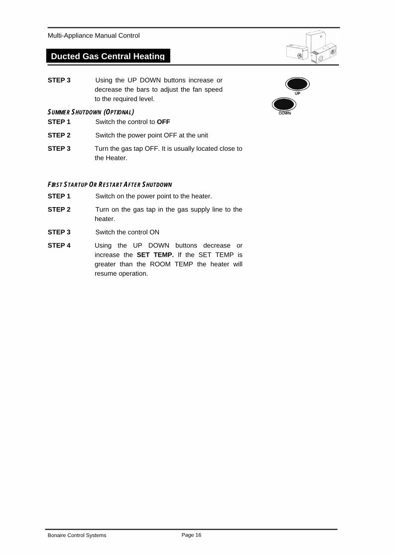
STEP 3 Using the UP DOWN buttons increase or decrease the bars to adjust the fan speed to the required level.
SUMMER SHUTDOWN (OPTIONAL) STEP 1 Switch the control to OFF
STEP 2 Switch the power point OFF at the unit
STEP 3 Turn the gas tap OFF. It is usually located close to the Heater.
FIRST STARTUP OR RESTART AFTER SHUTDOWN STEP 1 Switch on the power point to the heater.
STEP 2 Turn on the gas tap in the gas supply line to the heater.
STEP 3 Switch the control ON
STEP 4 Using the UP DOWN buttons decrease or increase the SET TEMP. If the SET TEMP is greater than the ROOM TEMP the heater will resume operation.
Bonaire Control Systems Page 16
Multi-Appliance Manual Control
Ducted Gas Central Heating
HEATER MAINTENANCE MAINTENANCE GENERAL
Return Air Grille Filter.
If your heating system has a filter in the return air grille, it is extremely important it is cleaned every 3 – 4 weeks during the operating period to ensure correct operation of the heating unit. Failure to do so may cause your heater to stop because of over temperature and cause an unnecessary service call not covered by warranty.
Electrical
Warning: Before commencing any maintenance work on your unit, isolate the power at the supply (Fuse Box).
No general maintenance is required to the electrical system.
A Licensed Electrician only should carry out electrical connections and maintenance.
Flue
The flue and cowl assembly should be clean and free of obstructions.
SCHEDULED MAINTENANCE
Note: It is essential that your central heater be maintained in accordance with Climate Technologies requirements. Failure to do so will affect the life of the product and reduce the level of efficiency which may also affect your warranty.
Your Ducted Gas Central Heater should be serviced at least every 2 years to ensure trouble free operation.
1. To ensure that your heater continues to operate at peak efficiency it is recommended that it be periodically serviced by a qualified service technician (for your nearest Climate Technologies service office refer to Service section of this document).
2. Fan blades, motors, ignition systems and burners should be checked. Heater cabinet and immediate surroundings should be kept clean and clear.
Bonaire Control Systems Page 17
Multi-Appliance Manual Control
Ducted Gas Central Heating
PROBLEM SOLVING.
Central Heater will not operate!
Question Y/N Solution
Yes Refer to question 4
Has the unit been run since installation? 1.
No Check the unit is turned on at the power point and the gas cock is turned on. Call the installer to commission the unit.
Yes Refer to question 3
Is the unit installed in a new home? 2.
No Refer to question 4
Yes Refer to question 4
Has the installer run the unit? 3.
No Check the unit is turned on at the power point and the gas cock is turned on. Call the installer to commission the unit.
Yes Turn the control off then on to reset unit. If the unit still does not start call for service. (refer to solution 6 for reset instructions)
Is the SET TEMP greater that the ROOM TEMP?
4.
No Increase the SET TEMP so the thermostat calls for heat.
Yes Reset the unit. This can be done by:
Turn the control OFF then ON. The unit should resume operation.
Has there been a known power surge? 5.
No Unit should operate normally. If not a service call will be required.
THIS TROUBLE SHOOTING GUIDE IS A REFERENCE ONLY.
FOR SERVICE OR WARRANTY REQUIREMENTS PLEASE REFER TO
THE WARRANTY SECTION OF THIS BOOK
Bonaire Control Systems Page 18
Multi-Appliance Manual Control
Dual Cycle – Refrigerated Air Conditioning
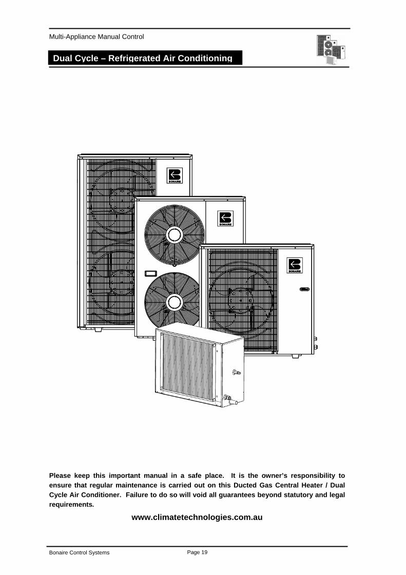
ADD-ON Refrigerated Air Conditioning
Owners Operating and Maintenance
Please keep this important manual in a safe place. It is the owner’s responsibility to ensure that regular maintenance is carried out on this Ducted Gas Central Heater / Dual Cycle Air Conditioner. Failure to do so will void all guarantees beyond statutory and legal requirements.
www.climatetechnologies.com.au
Bonaire Control Systems Page 19
Multi-Appliance Manual Control
Dual Cycle – Refrigerated Air Conditioning
GENERAL INFORMATION. IMPORTANT NOTICE. A licensed person is required to install Climate Technologies equipment. If the equipment is not installed in a accordance with the installation instructions and the governing body regulations, Climate Technologies reserves the right to refuse service on non compliant installations.
Subject to state regulations and by laws a certificate of compliance must be issued for the electrical and plumbing connections certifying that the work complies with all the relevant standards.
Note: Only a licensed person will have insurance protecting their workmanship.
DATA LOCATION. Your appliance model number, serial number and model description are located on the appliance data plate on the end of the ducted gas heater / Dual Cycle air conditioner in the vicinity of the electronic controls access. These details should also be in the warranty section of this booklet.
You will need this information, should your appliance require servicing, spare parts or just if you require additional information about this product.
ASSEMBLY. There is no assembly required of this Add-on Refrigerated Air Conditioner. Your Dealer or installer will carry out all assembly and commissioning upon installation.
SAFETY SAFETY & OWNER RESPONSIBILITY The manufacturer and its service providers reserve the right to refuse service unless safety and accessibility to the unit can be guaranteed. The cost of any extra equipment required to provide access to the unit for servicing is the responsibility of the owner.
PRECAUTIONS. DO NOT PLACE ARTICLES ON OR AGAINST THE CONDENSER.
DO NOT PLACE ARTICLES IN FRONT OF THE CONDENSER.
ENSURE THE CLEARANCES BETWEEN THE UNIT AND WALL ARE KEPT CLEAR.
DO NOT PLACE ARTICLES IN FRONT OF OR OVER THE RETURN AIR GRILLE.
FEATURES. Your Ducted Gas Central Heater and Add-on Refrigerated air conditioner has all the safety devices to ensure safe operation. These devices conform to the standards set out by the Australian Gas Association.
POWER INTERRUPTION. Should there be an interruption to the power supply during the cooling operation the controls will automatically shut down.
When the power is restored, the control will be in the OFF position and therefore will not resume operation until turned ON.
Bonaire Control Systems Page 20
Multi-Appliance Manual Control
Dual Cycle – Refrigerated Air Conditioning
USING YOUR CONTROL WITH DUAL CYCLE AIR CONDITIONING To operate your control simply press the ON / OFF button. The unit will then display the default or last used settings and will be ready to operate. Any changes made to the control settings will have a 3 second delay before the unit responds.
As the Dual Cycle Refrigerated Air Conditioner is connected in conjunction with a ducted gas central heater you may have to toggle through the modes to select the heating functions.
To select one of the modes below, simply push the MODE button until the screen displays the required settings. The following modes are available for the heater:
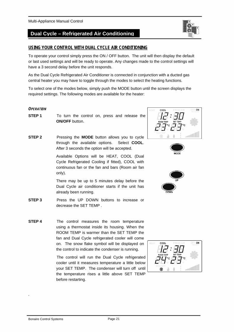
OPERATION STEP 1 To turn the control on, press and release the
ON/OFF button.
STEP 2 Pressing the MODE button allows you to cycle through the available options. Select COOL. After 3 seconds the option will be accepted.
Available Options will be HEAT, COOL (Dual Cycle Refrigerated Cooling if fitted), COOL with continuous fan or the fan and bars (Room air fan only).
There may be up to 5 minutes delay before the Dual Cycle air conditioner starts if the unit has already been running.
STEP 3 Press the UP DOWN buttons to increase or decrease the SET TEMP .
STEP 4 The control measures the room temperature using a thermostat inside its housing. When the ROOM TEMP is warmer than the SET TEMP the fan and Dual Cycle refrigerated cooler will come on. The snow flake symbol will be displayed on the control to indicate the condenser is running.
The control will run the Dual Cycle refrigerated cooler until it measures temperature a little below your SET TEMP. The condenser will turn off until the temperature rises a little above SET TEMP before restarting.
.
Bonaire Control Systems Page 21
Multi-Appliance Manual Control
Dual Cycle – Refrigerated Air Conditioning
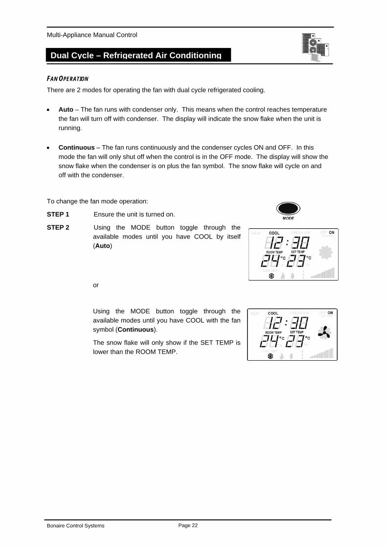
FAN OPERATION There are 2 modes for operating the fan with dual cycle refrigerated cooling.
• Auto – The fan runs with condenser only. This means when the control reaches temperature the fan will turn off with condenser. The display will indicate the snow flake when the unit is running.
• Continuous – The fan runs continuously and the condenser cycles ON and OFF. In this mode the fan will only shut off when the control is in the OFF mode. The display will show the snow flake when the condenser is on plus the fan symbol. The snow flake will cycle on and off with the condenser.
To change the fan mode operation:
STEP 1 Ensure the unit is turned on.
STEP 2 Using the MODE button toggle through the available modes until you have COOL by itself (Auto)
or
Using the MODE button toggle through the available modes until you have COOL with the fan symbol (Continuous).
The snow flake will only show if the SET TEMP is lower than the ROOM TEMP.
Bonaire Control Systems Page 22
Multi-Appliance Manual Control
Ducted Evaporative Air Conditioning
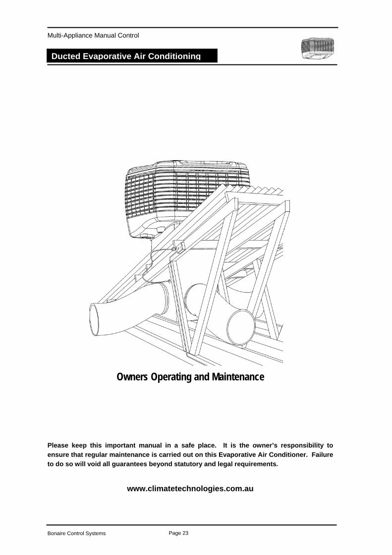
Ducted Evaporative Air Conditioning
Owners Operating and Maintenance
Please keep this important manual in a safe place. It is the owner’s responsibility to ensure that regular maintenance is carried out on this Evaporative Air Conditioner. Failure to do so will void all guarantees beyond statutory and legal requirements.
www.climatetechnologies.com.au
Bonaire Control Systems Page 23
Multi-Appliance Manual Control
Ducted Evaporative Air Conditioning
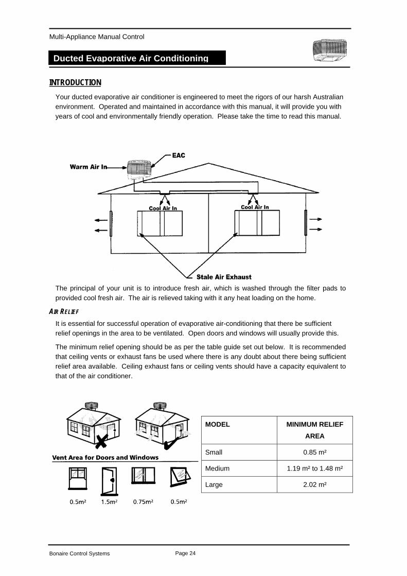
INTRODUCTION Your ducted evaporative air conditioner is engineered to meet the rigors of our harsh Australian environment. Operated and maintained in accordance with this manual, it will provide you with years of cool and environmentally friendly operation. Please take the time to read this manual.
The principal of your unit is to introduce fresh air, which is washed through the filter pads to provided cool fresh air. The air is relieved taking with it any heat loading on the home.
AIR RELIEF It is essential for successful operation of evaporative air-conditioning that there be sufficient relief openings in the area to be ventilated. Open doors and windows will usually provide this.
The minimum relief opening should be as per the table guide set out below. It is recommended that ceiling vents or exhaust fans be used where there is any doubt about there being sufficient relief area available. Ceiling exhaust fans or ceiling vents should have a capacity equivalent to that of the air conditioner.
MODEL MINIMUM RELIEF AREA
Small 0.85 m²
Medium 1.19 m² to 1.48 m²
Large 2.02 m²
Bonaire Control Systems Page 24

Multi-Appliance Manual Control
Ducted Evaporative Air Conditioning
DIALFLO BEED OFF
All evaporative air conditioners need some water bleed-off to prevent build-up of mineral deposits in the system. The correct setting of the bleed rate will ultimately govern the life of the unit.
With normal town water supply, in good water quality areas, bleed rate should be adjusted so that the discharge is not less than 10 litres per hour subject to unit size. Increased water hardness may require a higher bleed rate and increased maintenance.
Setting the BLEED OFF Rate.
To set the bleed rate locate the patented DIALFLO externally on one of the corner posts. Rotate the BLEED knob clockwise for more flow and anti clockwise.
Note: Hold the distribution knob (Filler) while setting the bleed rate as the distribution flow rate may go out of adjustment.
It is recommended that the bleed water is plumbed away to waste in accordance with local and state plumbing requirements.
Setting the Water Distribution Flow Rate
To set the water distribution flow rate to the filter pads, rotate filter knob anti-clockwise for more water and clockwise for less water. To control bleed-off rate rotate bleed dial clockwise for more water and anti-clockwise for less water.
Note: Hold the bleed knob while setting the distribution rate as the bleed rate may go out of adjustment.
OPTIONAL DUMP VALVE If a dump valve is fitted, the dump valve will only be activated when the pump is turned on or off. There is no dump time cycles, pre fill or pre cool with this manual control.
Bleed off may not be required in some areas, however it is the responsibility of the dealer / installer to correctly detirmine for your location.
Drainage from the dump valve needs also to be plumbed away in accordance with local and state plumbing requirements. Its Climate Technologies recommendation that the drain form the dump valve is plumbed to waste.
Bonaire Control Systems Page 25
Multi-Appliance Manual Control
Ducted Evaporative Air Conditioning
OPERATING THE MANUAL CONTROL. To operate your control simply press the ON OFF button. The unit will then display the default or last used settings and will be ready to operate. Any changes made to the control settings will have a 3 second delay before the unit responds.
If the evaporative cooler is connected in conjunction with a central heater you may have to toggle through the modes to select the evaporative cooling functions
To select the one of the modes below, simply push the mode button until the screen displays the required settings. The following modes are available for evaporative air conditioning.
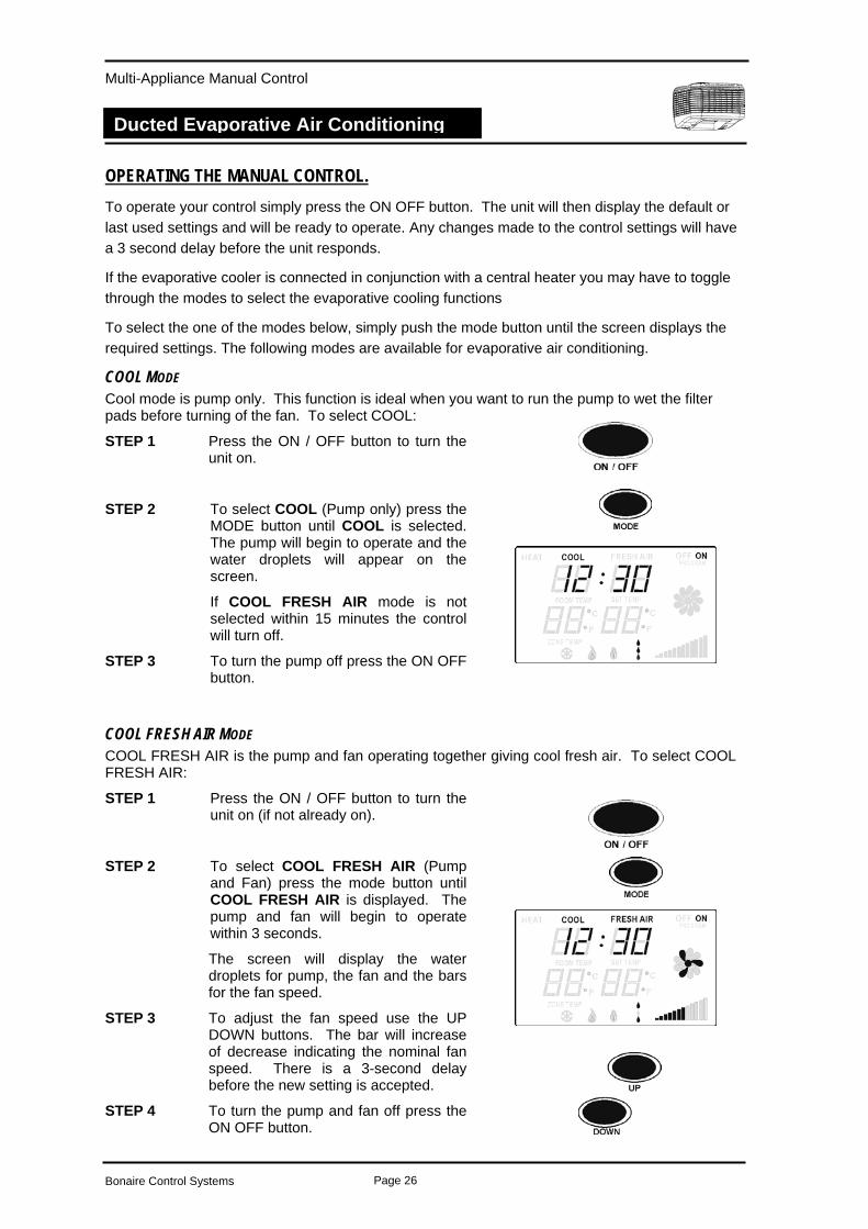
COOL MODE Cool mode is pump only. This function is ideal when you want to run the pump to wet the filter pads before turning of the fan. To select COOL:
STEP 1 Press the ON / OFF button to turn the unit on.
STEP 2 To select COOL (Pump only) press the MODE button until COOL is selected. The pump will begin to operate and the water droplets will appear on the screen.
If COOL FRESH AIR mode is not selected within 15 minutes the control will turn off.
STEP 3 To turn the pump off press the ON OFF button.
COOL FRESH AIR MODE COOL FRESH AIR is the pump and fan operating together giving cool fresh air. To select COOL FRESH AIR:
STEP 1 Press the ON / OFF button to turn the unit on (if not already on).
STEP 2 To select COOL FRESH AIR (Pump and Fan) press the mode button until COOL FRESH AIR is displayed. The pump and fan will begin to operate within 3 seconds.
The screen will display the water droplets for pump, the fan and the bars for the fan speed.
STEP 3 To adjust the fan speed use the UP DOWN buttons. The bar will increase of decrease indicating the nominal fan speed. There is a 3-second delay before the new setting is accepted.
STEP 4 To turn the pump and fan off press the ON OFF button.
Bonaire Control Systems Page 26
Multi-Appliance Manual Control
Ducted Evaporative Air Conditioning
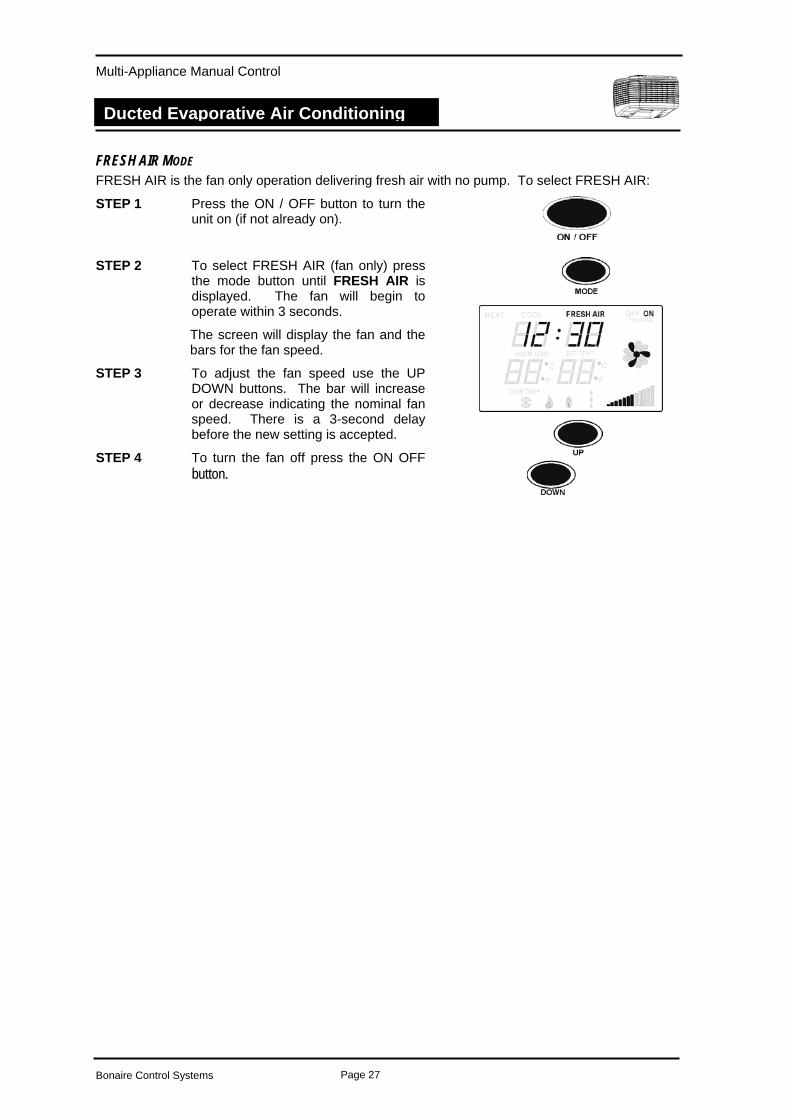
FRESH AIR MODE FRESH AIR is the fan only operation delivering fresh air with no pump. To select FRESH AIR:
STEP 1 Press the ON / OFF button to turn the unit on (if not already on).
STEP 2 To select FRESH AIR (fan only) press the mode button until FRESH AIR is displayed. The fan will begin to operate within 3 seconds.
The screen will display the fan and the bars for the fan speed.
STEP 3 To adjust the fan speed use the UP DOWN buttons. The bar will increase or decrease indicating the nominal fan speed. There is a 3-second delay before the new setting is accepted.
STEP 4 To turn the fan off press the ON OFF button.
Bonaire Control Systems Page 27
Multi-Appliance Manual Control
Ducted Evaporative Air Conditioning
DUCTED EVAPORATIVE AIR CONDITIONER MAINTENANCE GENERAL.
All Ducted Evaporative Air Conditioners benefit from some general maintenance to ensure continued cooling efficiency and a long life. Maintenance is carried out at the beginning and end of summer to start up and close down your unit.
We recommend that all maintenance work be undertaken by our fully trained and accredited Service Technicians or an authorised Climate Technologies Service Provider.
The frequency of general maintenance will depend on local operating conditions such as water quality, air borne dust and pollen.
It is essential that your evaporative air conditioner is maintained in accordance with this manual. Failure to do so will affect the life of the product, reduce the level of efficiency and may void warranty.
For service Australia wide refer to the details on the service section of this manual.
NOTE: The manufacturer and its agents reserve the right to refuse service unless safety and accessibility to the unit can be guaranteed. The cost of any extra equipment required to provide access to the unit for servicing is the responsibility of the owner.
SAFETY: Prior to commencing any maintenance isolate the unit at the power source. Ensure the roof is safe to access, your ladder is securely positioned and use suitable safety equipment.
FILTER PADS Visually check CELDEK pads for damage or blockage. Hose down pads from both sides to remove any build up of salts, dust and pollen. In dusty areas more regular cleaning is recommended. Check the water distributor, making sure it is clear and free from blockage. Failure to do so may lead to uneven water distribution and therefore less efficient operation.
WATER TANK It is important to keep the water tank clean and free from sediment and algae growth. To clean the tank, use a soft brush or similar. Wipe all surfaces in the tank while it is full of water (DO NOT FORGET THE PUMP STRAINER). Turn off the water inlet to the unit (an Isolation Valve should be fitted to the water inlet before the Float Valve). Drain the tank by removing the 40mm overflow pipe. It may be necessary to repeat this procedure if the tank is very dirty.
SAFETY: Wet roofs are dangerous – Take Care When Draining Tank.
WATER LEVEL / FLOAT VALVE The water level should be set at nominal 65-70mm from the top of the overflow before filter pads are saturated. After run off from operating filters the level from the top of the overflow fitting should be 25 – 30mm. The float valve is a mechanical type and is factory set. If it requires adjustment keep bends tight. If the valve is leaking the seal may require cleaning or replacing. Turn of the water. Remove the split pin and then float arm. Remove piston and clean or turn seal. Flush system and replace piston, float arm and split pin.
Note: Water supply line to float valve must be flushed before connecting.
Bonaire Control Systems Page 28
Multi-Appliance Manual Control
Ducted Evaporative Air Conditioning
Note: Some discharge from the overflow may be experienced after shut down due to water draining back from the Celdek pads. This is normal.
MOTOR AND FAN Check that the fan spins freely and that there is no build up on the blades.
ELECTRICAL No general maintenance is required to the electrical system.
A Qualified Electrician should only carry out electrical connections and maintenance.
BLEED OFF The bleed rate should be checked to ensure it is adequate and that there is no build up of mineral deposits in or on your air conditioner. White deposits indicate high mineral content and the Bleed Rate should be increased. If it is at maximum and the deposits are still forming, then more regular maintenance is required.
PUMP Check the pump spins freely and that the strainer is clean.
WATER DISTRIBUTION Check the water distribution system for blockage. Check the delivery tube for kinks or holes. Check that the clamps are secure and in place.
NO SEASONAL MAINTENANCE Your unit has been supplied with a dump valve system. As long as the dump valve has been fitted, there is no need for regular checking of the system during the operating (summer) period. This however does not remove the responsibility of the customer to have the unit service on an annual basis to check the unit function and to ensure the unit is clean and free from any mineral deposit build up.
Bonaire Control Systems Page 29
Multi-Appliance Manual Control
Ducted Evaporative Air Conditioning
TROUBLE SHOOTING GUIDE PROBLEM PROBABLE CAUSE REMEDY
A Black – out a Wait
b Tripped Circuit Breaker b Reset
c Blown Fuse c Replace Unit fails to start
d Electrical Fault d Call Climate Technologies Service Provider
a Pump Seized a Isolate power and then take off top of pump and try to free it. Some lubricant may help. Pump fails to
start b Pump Burnt Out b Call Climate Technologies
Service Provider
a Float Valve Leaking a Check adjustment or replace seal Water leaking
from overflow b Drain from Celdek Pads b Normal Operation
a Loose Delivery Tube a Check and tighten
b Break in tubing b Replace as necessary Water Droplets in air stream c Pump Delivers Excessive
Water to Pads c Adjust the Dialflo to reduce
the flow
a Inadequate Relief a Provide more open area to relieve stale air
Excessive humidity
b Outside humidity high b Turn pump off.
a Dirty Filters a Clean / Replace
b Dry Filters b Check water delivery system. Adjust if necessary.
Inadequate Cooling
c Dialflo not set correctly c Adjust Dialflo so that the pads have even saturation.
a Unit located near odor source a Remove source
b New Celdek filter smell b Smell will disappear after a period of operation (Approximately 48 hours or use).
Unpleasant Odor
Rapid formation of white deposits on pads
High Mineral Content Bleed off should be set at maximum. More regular maintenance may be required.
THIS TROUBLE SHOOTING GUIDE IS A REFERENCE ONLY. FOR SERVICE OR WARRANTY REQUIREMENTS PLEASE REFER
TO THE LAST PAGE OF THESE INSTRUCTIONS
Bonaire Control Systems Page 30
Multi-Appliance Manual Control
Controls – Installation / Setup / Commissioning
Control setup
SETTING UP THE CONTROL - GENERAL BEFORE STARTING Before attempting to use the setup instructions for the controls system, make sure the low voltage cable is connected and the 240 volt power has been turned on to the heater / cooler. The Low voltage controls are connected to the unit control box / controller via a 20-metre low voltage loom. NOTE: Do not run the low voltage loom in long parallel runs with 240V mains cables.
Keep the low voltage loom 200mm away from any long runs of mains wiring. Cross over mains wiring at right angles. Do not use existing access holes in wall cavities where 240V mains wiring exists. Drill a new access hole 200mm from the existing hole.
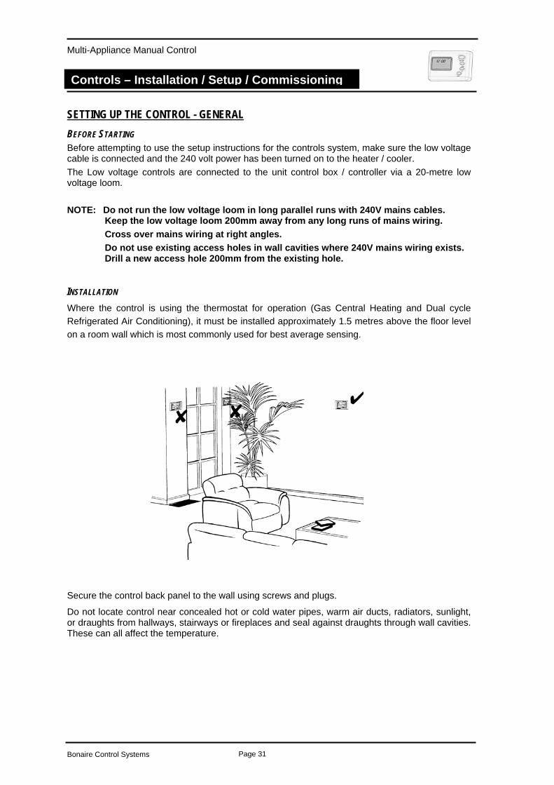
INSTALLATION Where the control is using the thermostat for operation (Gas Central Heating and Dual cycle Refrigerated Air Conditioning), it must be installed approximately 1.5 metres above the floor level on a room wall which is most commonly used for best average sensing.
Secure the control back panel to the wall using screws and plugs.
Do not locate control near concealed hot or cold water pipes, warm air ducts, radiators, sunlight, or draughts from hallways, stairways or fireplaces and seal against draughts through wall cavities. These can all affect the temperature.
Bonaire Control Systems Page 31
Multi-Appliance Manual Control
Controls – Installation / Setup / Commissioning
USING THE SETUP MODES There are a series of available parameters that can assist the installer to set the unit up to specification and tailor the control to meet the customer’s requirements. Carefully read these instructions before entering the maintenance modes. These set up features cover Ducted Evaporative Air Conditioning, Ducted Gas Central Heating and Add-on Refrigerated Air Conditioning.
The Setup modes include:
Diagnostics – All products
Fan Speed Settings – All products
PRODUCT IDENTIFICATION The setup mode will cater for many options of heating / cooling unit configurations. As a result there are a number of potential product classes that the manual control system will control. The class is the first requirement for selection when coding or entering the setup mode.
Ducted Gas Heating Only HEAT
Dual Cycle Refrigerated Air Conditioning COOL
Ducted Evaporative Air Conditioning COOL, FRESH AIR
Ducted Gas Heating and Evaporative Air Conditioning. HEAT, COOL FRESH AIR
CODING AUTO-CODING The manual control is only capable of controlling 1 product at a time. Options / combinations available are:
To code the unit communications:
STEP 1 Ensure the control and communication cable(s) are connected.
STEP 2 The moment the power is applied to the control system, the control will scan for all the new equipment that has been installed and powered on.
STEP 3 The powering up of a multiple configuration, a ducted central heater and a ducted evaporative air conditioner, must happen within 10 seconds of each other for the scan to find both units.
MANUAL CODING If the scan misses one of the units in a multiple configuration or you are adding a new product to the configuration:
STEP 1 Turn the thermostat ON.
STEP 2 Press and hold the ON / OFF button for 3 seconds to scan for the available products.
All the segments will be displayed during the coding period.
Bonaire Control Systems Page 32
Multi-Appliance Manual Control
Controls – Installation / Setup / Commissioning
IMPORTANT NOTES Things to note when connecting new products to a manual control
1. Central Heating will have a default configuration that includes add-on cooling. 2. When a ducted evaporative air conditioner is added to a ducted central heater, the add-on
cooling functions are no longer available for use. 3. The auto coding process can only discriminate between a single central heater and a
single evaporative air conditioner CALIBRATING THE THERMOSTAT. The thermostat comes pre-calibrated from the manufacturer. However, should the thermostat require re-calibrating, the following is the procedure.
STEP 1 Remove the control from the mounting panel
STEP 2 Power down the thermostat by disconnecting the comms loom.
STEP 3 Reconnect the comms loom to the thermostat. STEP 4 Wait 10 seconds for the control to complete
the autocode and then press the ON/OFF to enter the temperature setting
STEP 4 On the control board adjust the room temperature by rotating the temperature calibration knob.
There is only 20 seconds available after power up to make the adjustment. To further adjust repeat steps 2 and 3.
STEP 5 Replace the thermostat to the mounting base.
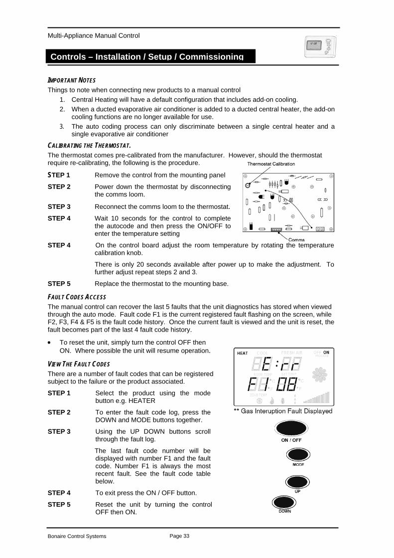
FAULT CODES ACCESS The manual control can recover the last 5 faults that the unit diagnostics has stored when viewed through the auto mode. Fault code F1 is the current registered fault flashing on the screen, while F2, F3, F4 & F5 is the fault code history. Once the current fault is viewed and the unit is reset, the fault becomes part of the last 4 fault code history.
• To reset the unit, simply turn the control OFF then ON. Where possible the unit will resume operation.
VIEW THE FAULT CODES There are a number of fault codes that can be registered subject to the failure or the product associated.
STEP 1 Select the product using the mode button e.g. HEATER
STEP 2 To enter the fault code log, press the DOWN and MODE buttons together.
STEP 3 Using the UP DOWN buttons scroll through the fault log.
The last fault code number will be displayed with number F1 and the fault code. Number F1 is always the most recent fault. See the fault code table below.
STEP 4 To exit press the ON / OFF button.
STEP 5 Reset the unit by turning the control OFF then ON.
Bonaire Control Systems Page 33
Multi-Appliance Manual Control
Controls – Installation / Setup / Commissioning
EVAPORATIVE AIR CONDITIONING SETUP
Fan Speed Options
Installer Maintenance Default Value Range
Low Fan Speed 13 0 – 35
High Fan Speed 35 0 – 35
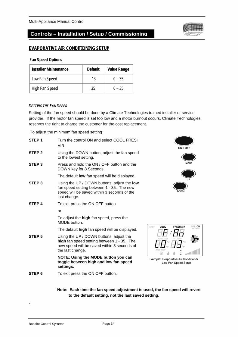
SETTING THE FAN SPEED Setting of the fan speed should be done by a Climate Technologies trained installer or service provider. If the motor fan speed is set too low and a motor burnout occurs, Climate Technologies reserves the right to charge the customer for the cost replacement. To adjust the minimum fan speed setting
STEP 1 Turn the control ON and select COOL FRESH AIR.
STEP 2 Using the DOWN button, adjust the fan speed to the lowest setting.
STEP 3 Press and hold the ON / OFF button and the DOWN key for 8 Seconds.
The default low fan speed will be displayed.
STEP 3 Using the UP / DOWN buttons, adjust the low fan speed setting between 1 - 35. The new speed will be saved within 3 seconds of the last change.
STEP 4 To exit press the ON OFF button
or
To adjust the high fan speed, press the MODE button.
The default high fan speed will be displayed.
STEP 5 Using the UP / DOWN buttons, adjust the high fan speed setting between 1 - 35. The new speed will be saved within 3 seconds of the last change.
NOTE: Using the MODE button you can toggle between high and low fan speed settings.
STEP 6 To exit press the ON OFF button.
Note: Each time the fan speed adjustment is used, the fan speed will revert to the default setting, not the last saved setting.
.
Bonaire Control Systems Page 34
Multi-Appliance Manual Control
Controls – Installation / Setup / Commissioning
DUCTED GAS CENTRAL HEATING
Fan Speed Options
Installer Maintenance Default Value Range
Low Fan Speed 27 0 – 35
High Fan Speed 35 0 – 35
High Fan Speed – Dual Cycle AC 35 35
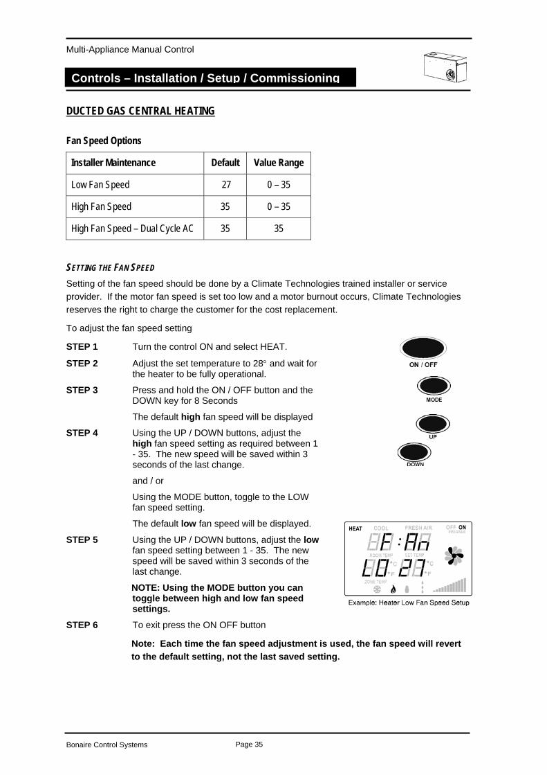
SETTING THE FAN SPEED Setting of the fan speed should be done by a Climate Technologies trained installer or service provider. If the motor fan speed is set too low and a motor burnout occurs, Climate Technologies reserves the right to charge the customer for the cost replacement.
To adjust the fan speed setting
STEP 1 Turn the control ON and select HEAT.
STEP 2 Adjust the set temperature to 28° and wait for the heater to be fully operational.
STEP 3 Press and hold the ON / OFF button and the DOWN key for 8 Seconds
The default high fan speed will be displayed
STEP 4 Using the UP / DOWN buttons, adjust the high fan speed setting as required between 1 - 35. The new speed will be saved within 3 seconds of the last change.
and / or
Using the MODE button, toggle to the LOW fan speed setting.
The default low fan speed will be displayed.
STEP 5 Using the UP / DOWN buttons, adjust the low fan speed setting between 1 - 35. The new speed will be saved within 3 seconds of the last change.
NOTE: Using the MODE button you can toggle between high and low fan speed settings.
STEP 6 To exit press the ON OFF button
Note: Each time the fan speed adjustment is used, the fan speed will revert to the default setting, not the last saved setting.
Bonaire Control Systems Page 35
Multi-Appliance Manual Control
Controls – Installation / Setup / Commissioning
COMMISSIONING CHECK LIST GENERAL
All equipment ordered by the customer is installed.
The unit is level and secure.
The mains and control wiring are complete and the circuit breaker and GPO are turned ON.
All Controller functions for the appliance operate.
All electrical or gas connections are to manufacturers specifications and the relevant electrical or gas standards and codes.
UNIT - DUCTED EVAPORATIVE AIR CONDITIONER
The water supply line has been flushed to clear swarf and debris and is free of leaks.
The tank is free of foreign matter and debris and the water isolating tap is turned ON.
Water drainpipe work is completed and sealed.
The water basin fills with water and the float valve closes correctly when the water level is 65-70mm below the overflow level.
The water pump operates correctly when turned ON at the controller.
The Dialflo water bleed rate is adjusted to suit local water conditions.
The Superclean Dump Valve (option). The tank drains correctly when unit turns off.
The fan deck is correctly located and the fan blade spins freely.
The fan operates through the entire speed range.
The minimum fan speed is correctly set.
Water distribution is even with the filter pads fitted and the air conditioner operating pump and fan.
UNIT – DUCTED HEATING
Electrical polarity of the power outlet is correct.
Heater is installed away from sources of dust and fumes (i.e. pool chlorine/petrol etc).
Gas leaks checked for, none present.
Flue outlet pipe complies with limits given / code and is sealed waterproof.
Combustion air meets requirements (internal, under floor).
Bonaire Control Systems Page 36
Multi-Appliance Manual Control
Controls – Installation / Setup / Commissioning
Fan speed set is correct.
Burner pressure is correct.
Mounting pad/platform complies with requirements / codes.
UNIT – DUAL CYCLE REFRIGERATED AIR CONDITIONING
Unit Foundation correct
All pipe work is welded and vacuumed down.
Condenser Coil is purged before charging.
System is charged, all joints checked and pressures set correctly
Condenser unit is level
All clearances around the condenser set to manufacturer's specifications.
DUCTWORK
All ductwork is completed to plan, correctly supported and airtight, with no bend less than 1.5 x the ductwork diameter.
Air distribution checked, dampers are adjusted and all outlets correctly adjusted and wiped clean.
All roof penetrations are fully sealed and watertight.
Man hole cover replaced.
SITE
All rubbish has been removed from inside and on the roof.
CUSTOMER HAND OVER
The operation of the Controller.
The need to open windows and doors for the correct operation of Evaporative Air Conditioning
The operation of the bleed or dumping system and it’s importance to operate at all times in a ducted evaporative air conditioner.
Maintenance requirements
Bonaire Control Systems Page 37
MULTI-APPLIANCE TOUCH PAD
Warranty – Australia
Warranty
IMPORTANT:
Please read this warranty information and complete the Dealer/Product information on the following page. KEEP this with your original purchase documents for any claim under warranty.
Firstly refer to your owners manual to ensure you have followed the correct operating procedures of your product, and refer to the trouble shooting guide to assist solving any problems you may have.
1. Read this warranty statement carefully before you request warranty service as items relation to installation are not covered by this appliance warranty.
2. A proof of product purchase must be provided for warranty service, to validate the appliance is within the manufacturer’s warranty periods.
3. This warranty is only for products and associated original controls for Climate Technologies manufactured product.
4. Only an authorised Climate Technologies service provider must carry out warranty service.
Climate Technologies provides the following Manufacturers warranty additional to all implied warranties and other statutory rights which you may have under the Trade Practices Act and similar State & Territory Laws, subject to the following terms and conditions.
Conditions to warranty
• Subject to the exclusions noted, Climate Technologies warrant the product for the period as prescribed in the table following this statement to be free from Inherent defects in materials and workmanship for functional and structural components.
• This product is only valid if the product is operated in accordance with the manufacturers instructions
• The appliance must not be modified or changed in any way. • Your proof of purchase MUST be produced before free service will be provided. • Traveling time and mileage are included within 30km of either your authorised Climate
Technologies dealer or service provider’s premises. Customers in areas other than the above are responsible for any traveling time and mileage required to carry out warranty repairs.
• The product must be installed by a qualified person in the manner prescribed by local & statutory regulations and to the manufacturer’s specifications.
• Service within the terms of this warranty will be recognised where we are satisfied that the appliance or part was supplied within the relevant time limits. Documents of purchase and Dealer/Installer information will assist in this process.
• Product fitness for purpose and overall system design / sizing is solely the responsibility of the dealer / installer. This includes but is not limited to heat load calculations, air flow, system balancing, humidity, water quality etc.
• The product must be installed in an easily and safe accessible area for service, appliances installed in areas not easily and safely assessable, costs will be borne by the owner for access equipment should maintenance be required.
DIY installation Warranty • If the product has been installed as a DIY, a supply part only warranty will apply. Parts
only will be supplied free of charge on the return of the faulty part and the owner will be responsible for all labour charges incurred for the part to be fitted by a qualified person. Labour warranty as prescribed in the following table is void in this situation.
Remote Location Warranty • If the product has been installed outside the Climate Technologies service network, a
supply part only warranty will apply. Parts only will be supplied free of charge on the return of the faulty part and the owner will be responsible for all labour charges incurred for the part to be fitted by a qualified person. Labour warranty as prescribed in the following table is void in this situation.
Bonaire Control Systems Page 38
MULTI-APPLIANCE TOUCH PAD
Warranty – Australia
Exclusions to warranty
• Consumable items subject to wear and tear such as filter pads, drive belts and bearings are not covered by this warranty.
• Components used as part of the installation such as grilles filters, ducting, fittings, zone motors and consumer services pipe work are warranted from your place of purchase and not covered by this warranty.
• Damage caused by elements such as wind, rain, lighting, floods etc along with power spiking and brownouts are not considered defective material or workmanship and as such are not considered warranty.
• No responsibility will be accepted for outside elements such as pests, animals, pets and vermin that may cause damage to the unit.
• Harsh environmental situations such as salt air that may cause cabinet damage / rusting can not be considered warranty.
• The manufacturer does not accept liability or any claims for damage to building contents, carpet, walls, ceilings, foundations or any other consequential loss either direct or indirect. Damage resulting from, power spikes, incorrect operation, incorrect installation, and incorrect maintenance is also not covered.
• All warranties are NOT transferable. Conditions where warranty may be void
• If there is no certificate of compliance for plumbing, electrical or refrigeration as required by State & Territory Laws. Climate Technologies reserves the right to refuse service on non-compliant installations.
• The defective operation of the appliance that is due to failure of electricity, gas, water or refrigerant gas supplied.
• Defects are caused by neglect, incorrect application, abuse or by accidental damage of the appliance.
• An unauthorised person has attempting to repair the appliance. • A situation arises referenced in the trouble-shooting guide. • A charge will be made for work done or for a service call where there is nothing wrong
with the appliance.
Bonaire Control Systems Page 39
MULTI-APPLIANCE TOUCH PAD
Warranty – Australia
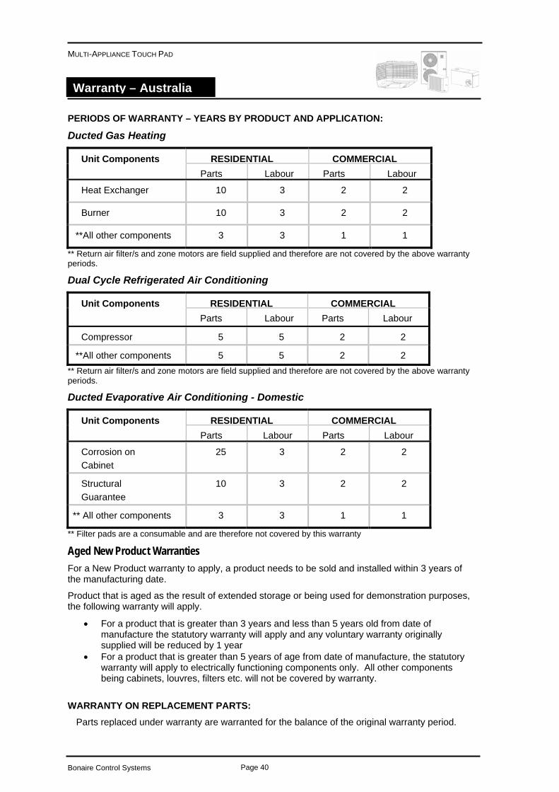
PERIODS OF WARRANTY – YEARS BY PRODUCT AND APPLICATION:
Ducted Gas Heating
RESIDENTIAL COMMERCIAL Unit Components Parts Labour Parts Labour
Heat Exchanger 10 3 2 2
Burner 10 3 2 2
**All other components 3 3 1 1
** Return air filter/s and zone motors are field supplied and therefore are not covered by the above warranty periods.
Dual Cycle Refrigerated Air Conditioning
RESIDENTIAL COMMERCIAL Unit Components Parts Labour Parts Labour
Compressor 5 5 2 2
**All other components 5 5 2 2 ** Return air filter/s and zone motors are field supplied and therefore are not covered by the above warranty periods. Ducted Evaporative Air Conditioning - Domestic
RESIDENTIAL COMMERCIAL Unit Components Parts Labour Parts Labour
Corrosion on Cabinet
25 3 2 2
Structural Guarantee
10 3 2 2
** All other components 3 3 1 1
** Filter pads are a consumable and are therefore not covered by this warranty
Aged New Product Warranties For a New Product warranty to apply, a product needs to be sold and installed within 3 years of the manufacturing date.
Product that is aged as the result of extended storage or being used for demonstration purposes, the following warranty will apply.
• For a product that is greater than 3 years and less than 5 years old from date of manufacture the statutory warranty will apply and any voluntary warranty originally supplied will be reduced by 1 year
• For a product that is greater than 5 years of age from date of manufacture, the statutory warranty will apply to electrically functioning components only. All other components being cabinets, louvres, filters etc. will not be covered by warranty.
WARRANTY ON REPLACEMENT PARTS:
Parts replaced under warranty are warranted for the balance of the original warranty period.
Bonaire Control Systems Page 40
MULTI-APPLIANCE TOUCH PAD
Warranty – Australia
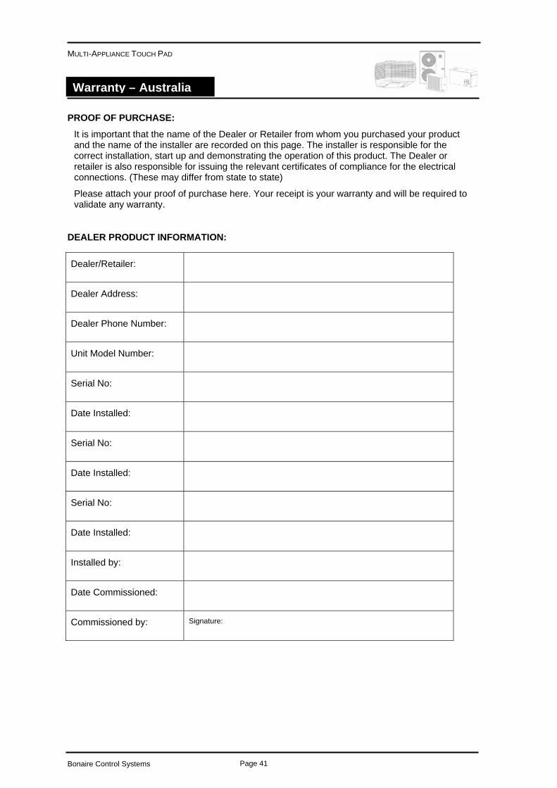
PROOF OF PURCHASE:
It is important that the name of the Dealer or Retailer from whom you purchased your product and the name of the installer are recorded on this page. The installer is responsible for the correct installation, start up and demonstrating the operation of this product. The Dealer or retailer is also responsible for issuing the relevant certificates of compliance for the electrical connections. (These may differ from state to state)
Please attach your proof of purchase here. Your receipt is your warranty and will be required to validate any warranty.
DEALER PRODUCT INFORMATION:
Dealer/Retailer:
Dealer Address:
Dealer Phone Number:
Unit Model Number:
Serial No:
Date Installed:
Serial No:
Date Installed:
Serial No:
Date Installed:
Installed by:
Date Commissioned:
Signature: Commissioned by:
Bonaire Control Systems Page 41
Multi-Appliance Manual Control
Service - Australia
SERVICE
SERVICE CENTRES:
Only qualified service personnel should conduct any service work carried out on your heating / cooling ducted system. It is important that periodical service is carried out on your product to ensure your will receive the efficiency benefits the product provides.
For Metro Service only ring the numbers below.
South Australia/ (08) 8307 5230
Northern Territory
New South Wales / (03) 8795 2457
Australian Capital Territory
Western Australia (08) 9454 1000
Victoria/Tasmania (03) 8795 2456
Queensland (03) 8795 2457
Outside Metro areas please contact your nearest Climate Technologies Service Provider.
New Zealand (ABERGAS LTD) 0800 161 161
Bonaire Control Systems Page 42
Multi-Appliance Manual Control
Service - Australia
Bonaire Control Systems Page 43

5312270/E
Manufactured by
Climate Technologies ABN 13 001 418 042
26 Nylex Avenue
Salisbury, SA 5108 Australia
www.climatetechnologies.com.au
Recommended