05L015R1
RELEASED FOR PUBLIC COMMENT
Secretariat: Standards Management DepartmentSIRIM Berhad (Company No. 367474-V)1, Persiaran Dato’ MenteriP.O. Box 7035, Section 240911 Shah AlamSelangor Darul EhsanMalaysia
Comment begins on Comments terminates on01- April 2006 31- May 2006
MOTORCYCLE CHAINS AND SPROCKETS – PART 1: MOTORCYCLES CHAIN – SPECIFICATION (FIRST REVISION)
THIS DOCUMENT IS A DRAFT CIRCULATED FOR COMMENT. IT IS THEREFORE SUBJECT TO CHANGE AND MAY NOT BE REFERRED TO AS A MALAYSIAN STANDARD UNTIL PUBLISHED AS SUCH.
(NAR/rz)
ICS: 43.140
Descriptors: Motorcycles chains, chains number, chains construction, chain performance requirement, chain dimension and chains test method
DRAFT MALAYSIAN STANDARD

ii
CONTENTS
Page
Committee representation ……….……………………………………………………… iii
Foreword………………………..…………………………………………………………. iv
1 Scope………………………..…………………………………………………………….. 1
2 Nomenclature, Designation and Construction ………………………………………… 1
3 Performance Requirement…………….………………………………………………… 4
4 Dimensions ...……………………………………………………………………………... 7
5 Test Methods………….…………………………………………………………………… 7
6 Rust Prevention ……….………………………………………………………………….. 10
7 Marking…………………….….…………………………………………………………… 10
Annexes
A Fatigue strength test method……………………………………………………………. 12B Wear resistance test method……………………………………………………………. 13
Tables
1 Chain number, recommended use and type…………………………………………… 22 Breaking load……………………………………………………………………………… 53 Fatigue limit……………………………………………………………………………….. 64 Hardness of the pin, bush and roller……………………………………………………. 65 Chain dimensions………………………………………………………………………… 86 Load for length measurement…………………………………………………………… 97 Testing conditions for chain wear resistance………………………………………….. 11
Figures
1 Roller chain, bush chain, seal chain and silent chain………………………………… 32 Outer and inner link of chain parts………………………………………………………. 33 Connecting link of chain parts…………………………………………………………… 34 Chain dimension………………………………………………………………………….. 7
i
Committee representation
The Road Vehicles Industry Standards Committee (ISC L) under whose authority this Malaysian Standard was developed, comprises representatives from the following organisations:
Automobile Association of MalaysiaDepartment of Environment MalaysiaDepartment of Standards MalaysiaJabatan Pengangkutan JalanMalaysian Automotive AssociationMinistry of International Trade and IndustryMotosikal dan Enjin Nasional Sdn BhdPerodua Manufacturing Sdn BhdPerusahaan Otomobil Nasional BerhadPolis DiRaja MalaysiaProton Vendor AssociationUniversiti Putra MalaysiaUniversiti Teknologi Malaysia
The Technical Committee on Motorcycles which developed this Malaysian Standard consists of representatives from the following organisations:
Armstrong Auto Parts Sdn Bhd
HL Yamaha Motor Research Centre Sdn Bhd
Jabatan Pengangkutan Jalan
Kawasaki Sunrock Sdn Bhd
Kayaba (M) Sdn Bhd
Kilang Rantai S.A Sdn Bhd
KL 21 Sdn Bhd
Motorcycles and scooter Assembler and Distributor Association of Malaysia
Motosikal dan Enjin Nasional Sdn Bhd
MZ Motorrad Sdn Bhd
Polis DiRaja Malaysia
Pusat Pemeriksaan Kenderaan Berkomputer Sdn Bhd
SIRIM Berhad (Secretariat)
Universiti Teknologi Malaysia
Universiti Putra Malaysia
ii
FOREWORD
This Malaysian Standard was developed by the Working Group on Chain and Sprocket under the authority of the Road Vehicles Industry Standards Committee.
This MS XXXX consists of the following parts, under the general title Specification for Motorcycle Chains and Sprockets:
Part 1: Motorcycle ChainsPart 2: Motorcycle Sprockets
This Malaysian Standard is the first revision of MS 996: Part 1 (P) 1985, Specification for Motorcycle Chains and Sprockets -Part 1: Motorcycle Chains.
Major modifications of this revision are as follows:
a) additional to the scope as its also covers seal chain and silent chain;
b) additional to the chain numbers , recommended use and type of chain in Table 1, Table 2 , Table 3 , Table 5, Table 6 and Table 7;
c) change to a new figure 1 and figure 4; and
d) rename a new Table 4 and additional notes to Table 4 as to covers seal chain and silent chain.
This revised Malaysian Standard cancels and replaces MS 996: Part 1: 1985 (P).
Compliance with a Malaysian Standard does not of itself confer immunity from legal obligations.
iii
MOTORCYCLE CHAINS AND SPROCKETSPART 1: MOTORCYCLE CHAINS - SPECIFICATION
1. Scope
1.1 This Malaysian Standard specifies dimensions, material and performance requirements for chains for use on motorcycles.
1.2 This standard covers bush chains, roller chains, seal chain and silent chain.
1.3 Chains covered by this standard are suitable for use as drive chains, cam chains, oil pump chain or balancer chains as specified.
2. Nomenclature, designation and construction
2.1 Nomenclature
For the purpose of this standard, the nomenclature given below and in Figures 2 and 3 shall apply.
2.1.1 Roller chain
A chain constructed with rollers around the bushes.
2.1.2 Bush chain
A chain constructed without rollers.
2.1.3 Seal Chain
A chain constructed with seal and roller around the bushes
2.1.4 Silent Chain
A chain constructed with pin and plate only
2.2 Designation
Chains specified in this standard shall be designated by chain numbers as given in Table 1. The recommended application for each chain type is also given in Table 1.
2.3 Chain construction
2.3.1 A chain shall be assembled by fitting inner links and outer links alternately.
2.3.2 Chain components, referred to in this standard, are illustrated in Figure 1.
2.3.3 Details of outer and inner link shall be as illustrated in Figure 2.
2.3.4 Details of the types of connecting links that shall be used are illustrated in Figure 3. Connecting links shall be either of the spring clip-type or rivetted-type.
1
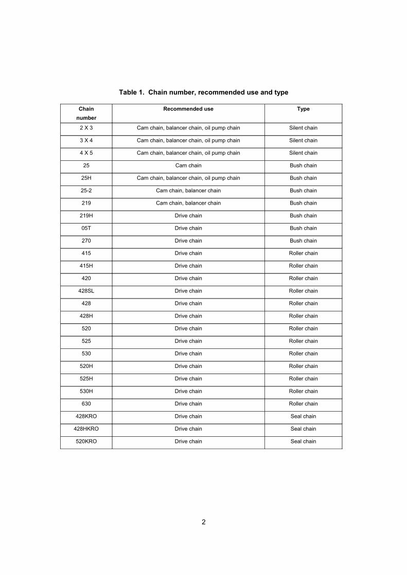
Table 1. Chain number, recommended use and type
Chain
number
Recommended use Type
2 X 3 Cam chain, balancer chain, oil pump chain Silent chain
3 X 4 Cam chain, balancer chain, oil pump chain Silent chain
4 X 5 Cam chain, balancer chain, oil pump chain Silent chain
25 Cam chain Bush chain
25H Cam chain, balancer chain, oil pump chain Bush chain
25-2 Cam chain, balancer chain Bush chain
219 Cam chain, balancer chain Bush chain
219H Drive chain Bush chain
05T Drive chain Bush chain
270 Drive chain Bush chain
415 Drive chain Roller chain
415H Drive chain Roller chain
420 Drive chain Roller chain
428SL Drive chain Roller chain
428 Drive chain Roller chain
428H Drive chain Roller chain
520 Drive chain Roller chain
525 Drive chain Roller chain
530 Drive chain Roller chain
520H Drive chain Roller chain
525H Drive chain Roller chain
530H Drive chain Roller chain
630 Drive chain Roller chain
428KRO Drive chain Seal chain
428HKRO Drive chain Seal chain
520KRO Drive chain Seal chain
2
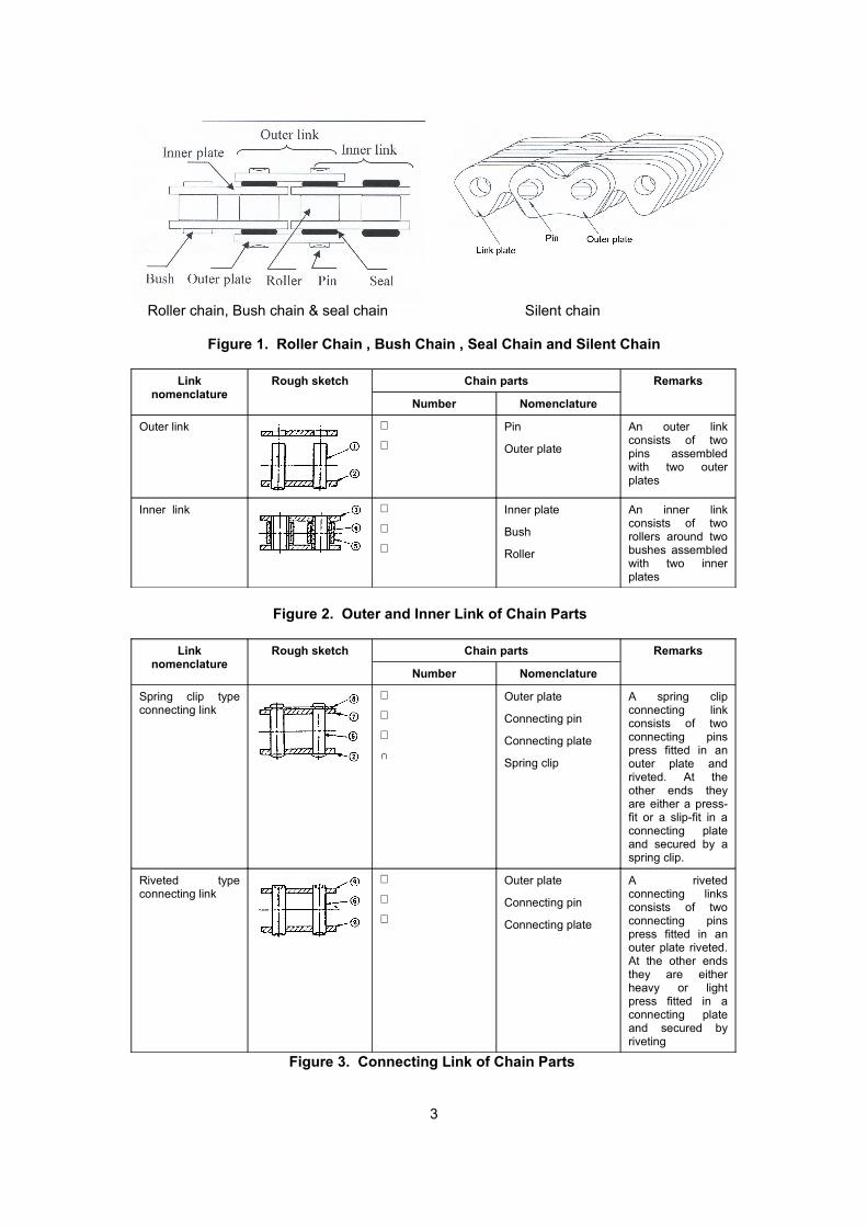
Roller chain, Bush chain & seal chain Silent chain
Figure 1. Roller Chain , Bush Chain , Seal Chain and Silent Chain
Link nomenclature
Rough sketch Chain parts Remarks
Number Nomenclature
Outer link ℵ
ℑPin
Outer plate
An outer link consists of two pins assembled with two outer plates
Inner link ℜ
℘
⊗
Inner plate
Bush
Roller
An inner link consists of two rollers around two bushes assembled with two inner plates
Figure 2. Outer and Inner Link of Chain Parts
Link nomenclature
Rough sketch Chain parts Remarks
Number Nomenclature
Spring clip type connecting link
ℑ
⊕
∅
∩
Outer plate
Connecting pin
Connecting plate
Spring clip
A spring clip connecting link consists of two connecting pins press fitted in an outer plate and riveted. At the other ends they are either a press-fit or a slip-fit in a connecting plate and secured by a spring clip.
Riveted type connecting link
ℑ
⊕
∪
Outer plate
Connecting pin
Connecting plate
A riveted connecting links consists of two connecting pins press fitted in an outer plate riveted. At the other ends they are either heavy or light press fitted in a connecting plate and secured by riveting
Figure 3. Connecting Link of Chain Parts
3
3. Performance requirements
3.1 Breaking load
The minimum breaking loads of chains, when tested in accordance with the method specified in 5.1 shall be as given in Table 2.
3.2 Length
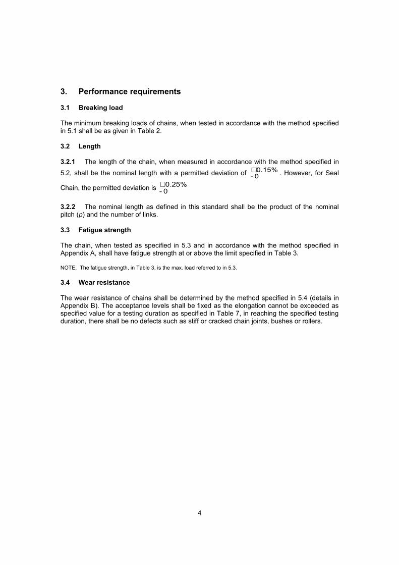
3.2.1 The length of the chain, when measured in accordance with the method specified in
5.2, shall be the nominal length with a permitted deviation of 0.15% 0 -
+ . However, for Seal
Chain, the permitted deviation is 0.25% 0 -
+
3.2.2 The nominal length as defined in this standard shall be the product of the nominal pitch (p) and the number of links.
3.3 Fatigue strength
The chain, when tested as specified in 5.3 and in accordance with the method specified in Appendix A, shall have fatigue strength at or above the limit specified in Table 3.
NOTE. The fatigue strength, in Table 3, is the max. load referred to in 5.3.
3.4 Wear resistance
The wear resistance of chains shall be determined by the method specified in 5.4 (details in Appendix B). The acceptance levels shall be fixed as the elongation cannot be exceeded as specified value for a testing duration as specified in Table 7, in reaching the specified testing duration, there shall be no defects such as stiff or cracked chain joints, bushes or rollers.
4
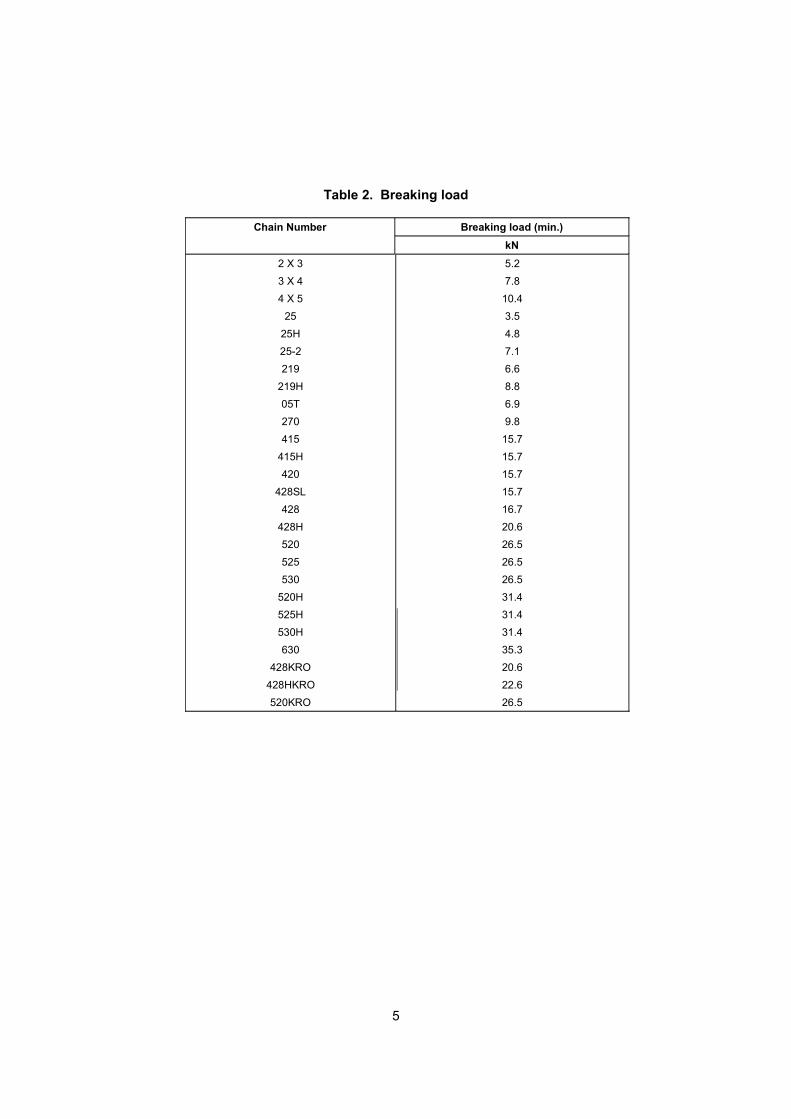
Table 2. Breaking load
Chain Number Breaking load (min.)
kN
2 X 3
3 X 4
4 X 5
25
25H
25-2
219
219H
05T
270
415
415H
420
428SL
428
428H
520
525
530
520H
525H
530H
630
428KRO
428HKRO
520KRO
5.2
7.8
10.4
3.5
4.8
7.1
6.6
8.8
6.9
9.8
15.7
15.7
15.7
15.7
16.7
20.6
26.5
26.5
26.5
31.4
31.4
31.4
35.3
20.6
22.6
26.5
5
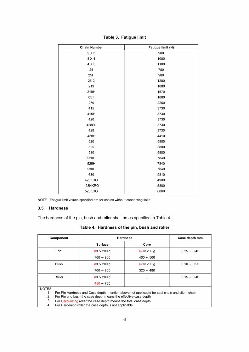
Table 3. Fatigue limit
Chain Number Fatigue limit (N)
2 X 3
3 X 4
4 X 5
25
25H
25-2
219
219H
05T
270
415
415H
420
428SL
428
428H
520
525
530
520H
525H
530H
630
428KRO
428HKRO
520KRO
980
1080
1180
780
980
1280
1080
1570
1080
2260
3730
3730
3730
3730
3730
4410
5880
5880
5880
7840
7840
7840
9810
4900
5880
6860
NOTE. Fatigue limit values specified are for chains without connecting links.
3.5 Hardness
The hardness of the pin, bush and roller shall be as specified in Table 4.
Table 4. Hardness of the pin, bush and roller
Component Hardness Case depth mm
Surface Core
Pin mHv 200 g
700 ~ 900
mHv 200 g
400 ~ 500
0.25 ~ 0.45
Bush mHv 200 g
700 ~ 900
mHv 200 g
320 ~ 480
0.10 ~ 0.25
Roller mHv 200 g
450 ~ 700
_ 0.15 ~ 0.40
NOTES:1. For Pin Hardness and Case depth mention above not applicable for seal chain and silent chain 2. For Pin and bush the case depth means the effective case depth 3. For Carburizing roller the case depth means the total case depth 4. For Hardening roller the case depth is not applicable
6
3.6 Other requirements
The finished chain shall be free from stiff joints and rollers.
4. Dimensions
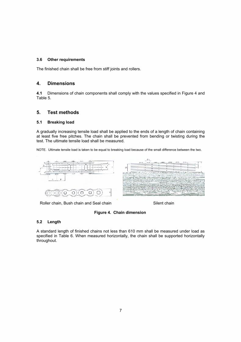
4.1 Dimensions of chain components shall comply with the values specified in Figure 4 and Table 5.
5. Test methods
5.1 Breaking load
A gradually increasing tensile load shall be applied to the ends of a length of chain containing at least five free pitches. The chain shall be prevented from bending or twisting during the test. The ultimate tensile load shall be measured.
NOTE. Ultimate tensile load is taken to be equal to breaking load because of the small difference between the two.
Roller chain, Bush chain and Seal chain Silent chain
Figure 4. Chain dimension
5.2 Length
A standard length of finished chains not less than 610 mm shall be measured under load as specified in Table 6. When measured horizontally, the chain shall be supported horizontally throughout.
7
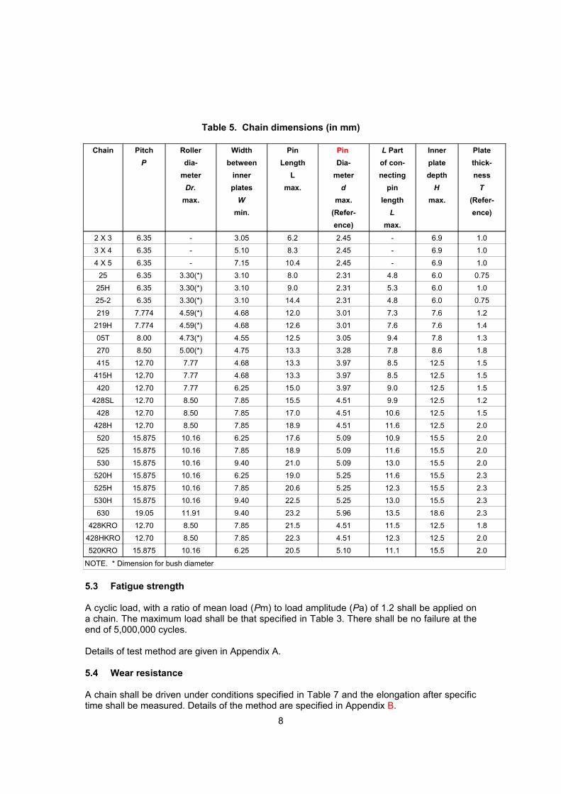
Table 5. Chain dimensions (in mm)
Chain Pitch
P
Roller
dia-
meter
Dr.
max.
Width
between
inner
plates
W
min.
Pin
Length
L
max.
Pin
Dia-
meter
d
max.
(Refer-
ence)
L Part
of con-
necting
pin
length
L
max.
Inner
plate
depth
H
max.
Plate
thick-
ness
T
(Refer-
ence)
2 X 3 6.35 - 3.05 6.2 2.45 - 6.9 1.0
3 X 4 6.35 - 5.10 8.3 2.45 - 6.9 1.0
4 X 5 6.35 - 7.15 10.4 2.45 - 6.9 1.0
25 6.35 3.30(*) 3.10 8.0 2.31 4.8 6.0 0.75
25H 6.35 3.30(*) 3.10 9.0 2.31 5.3 6.0 1.0
25-2 6.35 3.30(*) 3.10 14.4 2.31 4.8 6.0 0.75
219 7.774 4.59(*) 4.68 12.0 3.01 7.3 7.6 1.2
219H 7.774 4.59(*) 4.68 12.6 3.01 7.6 7.6 1.4
05T 8.00 4.73(*) 4.55 12.5 3.05 9.4 7.8 1.3
270 8.50 5.00(*) 4.75 13.3 3.28 7.8 8.6 1.8
415 12.70 7.77 4.68 13.3 3.97 8.5 12.5 1.5
415H 12.70 7.77 4.68 13.3 3.97 8.5 12.5 1.5
420 12.70 7.77 6.25 15.0 3.97 9.0 12.5 1.5
428SL 12.70 8.50 7.85 15.5 4.51 9.9 12.5 1.2
428 12.70 8.50 7.85 17.0 4.51 10.6 12.5 1.5
428H 12.70 8.50 7.85 18.9 4.51 11.6 12.5 2.0
520 15.875 10.16 6.25 17.6 5.09 10.9 15.5 2.0
525 15.875 10.16 7.85 18.9 5.09 11.6 15.5 2.0
530 15.875 10.16 9.40 21.0 5.09 13.0 15.5 2.0
520H 15.875 10.16 6.25 19.0 5.25 11.6 15.5 2.3
525H 15.875 10.16 7.85 20.6 5.25 12.3 15.5 2.3
530H 15.875 10.16 9.40 22.5 5.25 13.0 15.5 2.3
630 19.05 11.91 9.40 23.2 5.96 13.5 18.6 2.3
428KRO 12.70 8.50 7.85 21.5 4.51 11.5 12.5 1.8
428HKRO 12.70 8.50 7.85 22.3 4.51 12.3 12.5 2.0
520KRO 15.875 10.16 6.25 20.5 5.10 11.1 15.5 2.0
NOTE. * Dimension for bush diameter
5.3 Fatigue strength
A cyclic load, with a ratio of mean load (Pm) to load amplitude (Pa) of 1.2 shall be applied on a chain. The maximum load shall be that specified in Table 3. There shall be no failure at the end of 5,000,000 cycles.
Details of test method are given in Appendix A.
5.4 Wear resistance
A chain shall be driven under conditions specified in Table 7 and the elongation after specific time shall be measured. Details of the method are specified in Appendix B.
8
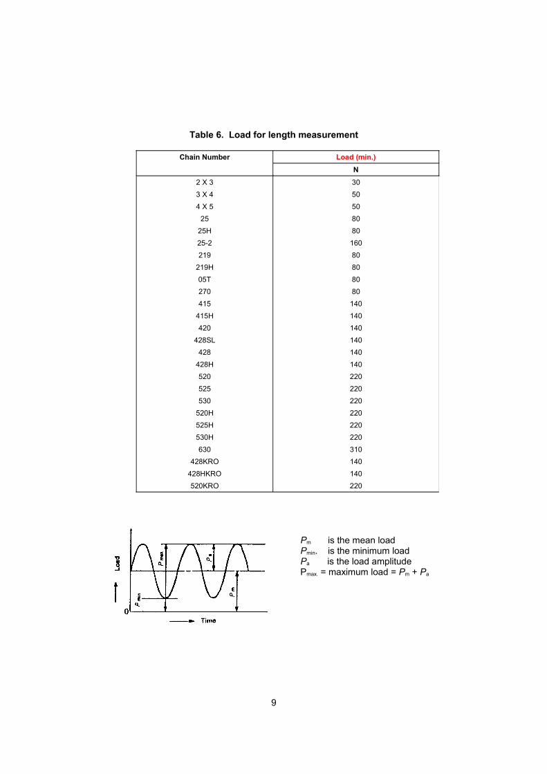
Table 6. Load for length measurement
Chain Number Load (min.)
N
2 X 3
3 X 4
4 X 5
25
25H
25-2
219
219H
05T
270
415
415H
420
428SL
428
428H
520
525
530
520H
525H
530H
630
428KRO
428HKRO
520KRO
30
50
50
80
80
160
80
80
80
80
140
140
140
140
140
140
220
220
220
220
220
220
310
140
140
220
Pm is the mean loadPmin. is the minimum loadPa is the load amplitudePmax. = maximum load = Pm + Pa
9
6. Rust prevention
6.1 Chains shall be appropriately treated to prevent rusting.
7. Marking
7.1 All chains shall be marked with the manufacturer’s name (or trade-mark) and chain number on the outer plate.
10
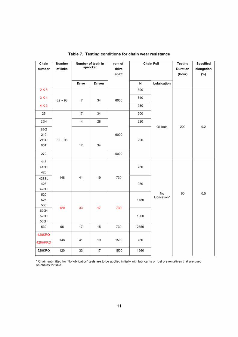
Table 7. Testing conditions for chain wear resistance
Chain
number
Number
of links
Number of teeth in sprocket
rpm of
drive
shaft
Chain Pull Testing
Duration
(Hour)
Specified
elongation
(%)
Drive Driven N Lubrication
2 X 3
82 ~ 98 17 34 6000
390
Oil bath 200 0.2
3 X 4 640
4 X 5 930
25
82 ~ 98
17 34
6000
200
25H 14 28 220
25-2
219
219H
05T 17 34
290
270 5000
415
415H
420
148 41 19 730
780
No lubrication*
60 0.5
428SL
428
428H
980
520
525
530120 33 17 730
1180
520H
525H
530H
1960
630 96 17 15 730 2650
428KRO
148 41 19 1500 780428HKRO
520KRO 120 33 17 1500 1960
* Chain submitted for ‘No lubrication’ tests are to be applied initially with lubricants or rust preventatives that are used on chains for sale.
11
Annex A
Fatigue strength test method
A1. Chains for test
Chains submitted for this test shall be those which have been manufactured and tested as required by this standard.
A2. Testing machine
The testing machine shall be capable of subjecting the chain to a cyclic load, as required in 5.3 of the standard. In addition, it shall have the following auxiliary devices:
a) an indicator to show the load applied;
b) a counter to indicate the number of cycles completed;
c)a device to prevent the machine from being restarted, following a stoppage due to breakdown in electricity supply or any other reason; and
d) an automatic stoppage device.
The machine shall operate at between 500 cycles and 3000 cycles per minute.
A3. Method of test
A3.1 A chain for test shall contain 5 to 7 free pitches excluding those for shackles.
A3.2 The chain shall be fixed to the shackles in such a manner that when loaded in tension, the load is evenly distributed on every link, with no twisting or bending. Counting shall start only after the chain is loaded as specified.
A3.4 There should be no break in the test. In the event that the chain does not fail at the end of 5 x 10⁶ cycles, the test shall be stopped. The machine should stop automatically should the chain break during the course of the test.
12
Annex B
Wear resistance test method
B1. Chains for test
Chains submitted for this test shall be those which have been manufactured as required by the standard.
B2. Testing machine
The testing machine shall contain the following components.
a) a power source to drive a variable speed motor;
b) a driver shaft and sprocket which can be easily assembled and disassembled;
c) a driven shaft and sprocket which can be easily assembled and disassembled;
d) a device capable of loading the chain as required; and
e) a device capable of adjusting the taut span of the chain.
The machine shall be so designed that the chain is subjected to taut and slack spans thus preventing the overheating of the chain.
B3. Testing method
B3.1 A chain for test shall be mounted on the testing machine after its length has been measured as specified in the standard.
B3.2 The chain shall be driven under conditions specified in Table 7. The test shall be continued until the specified elongation is reached. During the test, the chain shall be measured at least twice.
B3.3 Measurement of length shall cover at least 1 5 pitches.
B3.4 Measurements shall be taken when the chain is at room temperature.
B3.5 Chains for which the testing condition specifies that no lubrication is required, shall not be lubricated during intervals when length measurement is carried out.
B3.6 When lubrication is required, lubricants of grade SAE 10W 30 to 40 or equivalent shall be used.
13
B4. Treatment of test results
B4.1 A graph of chain elongation against time shall be plotted.
B4.2 The time required for the specified elongation shall be obtained from the curve plotted.
B4.3 In the event that the chain cannot be driven up to the specified elongation due to chain failure, stiff links or roller cracks, the test report shall indicate the duration for which the test had been carried out and the reason for non-completion of the test.
14
Acknowledgments
Technical Committee on Motorcycles members:
Y. Bhg. Dato’ Syed Mohammad Aidid (Chairman) Motorcycles and scooter Assembler and Distributor Association of Malaysia
Puan Nor Anisazila Bt Abdul Rahim (Secretary) SIRIM Berhad Encik Khalili Zulkifli Armstrong Auto Parts Sdn BhdEncik Tan Teik Ghee HL Yamaha Motor Research Centre
Sdn BhdIr Mohamad Dalib Jabatan Pengangkutan JalanEncik Lim Chee Sing Kawasaki Sunrock Sdn Bhd Encik Che Muhammad Kamil Mukhtar Kayaba (M) Sdn BhdEncik Lee Thian Chai Kilang Rantai S.A Sdn BhdKapten Mohd Sabri KL 21 Sdn BhdEncik Chee Kok Leong Motorcycles and scooter Assembler and Distributor Association of
Malaysia Encik Mohd Fadzil Abdullah Motosikal dan Enjin Nasional Sdn BhdEncik Mohammad Huzaini Haron MZ Motorrad Sdn BhdASP Zainal Abdul Hamid Polis DiRaja MalaysiaEncik Azlan Abu SamahPusat Pemeriksaan Kenderaan Berkomputer Sdn Bhd Cik Nurulakmar Abu Husain Universiti Teknologi MalaysiaProf Madya Dr Wong Shaw Voon Universiti Putra Malaysia
Working Group on Chain and Sprocket members:
Encik Lee Thian Chai (Chairman) Kilang Rantai S.A Sdn BhdPuan Nor Anisazila Bt Abdul Rahim (Secretary) SIRIM BerhadEncik Teoh Ching Hua Kilang Rantai S.A Sdn BhdEncik Lim Chin Yong Kilang Rantai S.A Sdn BhdEncik Heng Jeng Sheng Excel Rim Sdn BhdEncik Tang Chiang Bu Kilang Rantai S.A Sdn BhdEncik Tan Eng Chun Kilang Sprocket S.A Sdn Bhd
Recommended