B SERIES
C SERIES
MORIN B AND C SERIES ACTUATORS
B series - Ductile iron w/ stainless steel cylinders, C series - Ductile iron w/ carbon steel cylindersSpring return and double acting actuators Quarter-turn output torques to 158200 Nm
FEATURES AND BENEFITS
• Ductile iron housing, piston and end caps provide long life and durable, cost-effective operation.
• High strength alloy steel or 17-4PH stainless output shaft transmits torque without fatigue.
• Sintered bronze or PTFE composite output shaft bushings eliminate side loading of valve stem to maximize stem packing performance.
• Strong, corrosion-resistant chrome-plated steel piston rod for enduring high cycle applications.
• Sintered bronze piston rod bushings provide low-friction support and precise alignment to increase efficiency, reduce maintenance and extend actuator life.
• Heat-treated stainless steel thrust pin and rollers transfer piston force to yoke to reduce friction for longer life and more efficient torque transmission.
• PTFE guide bands ensure low-friction piston guidance, protecting cylinder walls from scoring and extending seal performance with a continuous cylinder wiping action.
• Bi-directional travel stops provide accurate valve rotation adjustment.
• NAMUR drive slot maintains a compact assembly for accessory-driven components with no couplings necessary.
• Tectyl-coated springs need no special tools to be disarmed safely and easily, reducing down time.
• Easily removable housing cover provides easy access for yoke mechanism inspection.
ALGA/ALGAS models available over the 1150 size
TECHNICAL DATA
Supply pressure: 3 to 11 barg(see torque chart)
Supply medium: Air or any gas compatible with materials of construction
Temperature ratingStandard range: -29°C to 99°COptional range: -54°C to 149°CAngular rotation: 90 degrees
(adjustable between 82 and 98 degrees)
Mounting pattern: ISO 5211Protection: IP66Certification: SIL3 capable
VCTDS-08437-EN 18/02
GENERAL APPLICATIONS
For remote control of any quarter-turn application: ball, butterfly, rotary plug or damper style valves, etc. for use in chemical process, food and beverage, iron and steel, pharmaceutical, power, oil and gas, pulp and paper and textile industries.
Copyright © Biffi. All rights reserved.www.biffi.it

2
STANDARD DESIGN, SCOTCH YOKE GUIDE BAR DESIGN, SCOTCH YOKE
MORIN B AND C SERIES ACTUATORS
DESIGNED WITH A RUGGED HEART
Scotch yoke design The heart of any scotch yoke actuator is the yoke. B and C series actuators use either 17-4PH or ductile iron for this critical area as standard. The yoke is the mechanism used to convert linear force to torque. The yoke is critical to actuator performance, it must be rugged yet precisely machined to give long life at high efficiency - all our yoke designs meet this test.
Principles of constructionUsing high quality materials of construction and modern rugged design concepts, provides the standard for high quality, low cost valve actuation.The actuator housings are all machined from ductile iron castings. This produces a rugged, low cost product through reduced machining time and by eliminating wasteful excess material. Any components that rotate or slide during operation, such as the high strength output shaft, chrome-plated piston rod, stainless steel thrust pin or the ductile iron piston, are all supported by replaceable friction reducing bearings.
Bi-directional travel stopsAdjustable stops on each end cap provide the flexibility of accurate valve rotation positioning at the end of the ‘open’ and ‘close’ stroke. Both stops are located on the cylinder centerline, the optimal position to maximize travel adjustment and eliminate any detrimental side loading on the travel stops. Adjustable from 82° to 98°.
Spring designed for safetyAll spring return models incorporate a ‘man safe’ spring design that allows the actuator to be safely assembled and disassembled in the field without the need for special tools. The integral tie rods are bored and tapped to provide a means of loading and unloading the spring in a safe and convenient manner.
Experts in actuator designWe understand that the most efficient design for one torque range is not the most efficient for another. Our actuators use the standard scotch yoke design for lower torque ranges and a guide bar design for the higher torque ranges. This gives a rugged design with economic cost.
3
MORIN B AND C SERIES ACTUATORS
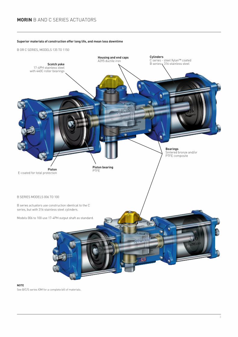
NOTESee B/C/S series IOM for a complete bill of materials.
Superior materials of construction offer long life, and mean less downtime
B OR C SERIES, MODELS 135 TO 1150
Scotch yoke17-4PH stainless steel
with 440C roller bearings
Housing and end capsA395 ductile iron
CylindersC series - steel Xylan™ coatedB series - 316 stainless steel
Piston bearingPTFEPiston
E-coated for total protection
BearingsSintered bronze and/orPTFE composite
B SERIES MODELS 006 TO 100
B series actuators use construction identical to the C series, but with 316 stainless steel cylinders.
Models 006 to 100 use 17-4PH output shaft as standard.

4
900
140
100
120
80
60
40
20
MORIN B AND C SERIES ACTUATORS
SYMMETRICAL AND CANTED YOKES
It’s about fitting the torque curve of the actuator to the valve . . .It’s about lower cost, lighter weight, smaller actuators . . .It’s about CHOICE . . .
SymmetricSymmetrical yoke design offers the standard torque curve seen most often in relation to scotch yoke actuators. It offers the increased torque advantage at both ends of the 90° stroke as shown on the blue curve below. This torque curve covers most quarter-turn applications.
CantedCanted yoke design moves the torque curve to where it’s needed most, gaining as much as 35% more break and reseat torque for the same size actuator. The canted yoke curve is shown in red below. Canted yoke actuators allow selection of smaller, lighter, and less expensive actuator packages.
Actuator rotation (degrees)
SymmetricCanted
Torq
ue o
utpu
t (pe
rcen
t)

5
±°C/°F
MORIN B AND C SERIES ACTUATORS
Partial stroke test device (PSTD)Provides a method of testing ESD packages without shutdown.
LockoutIntegral lockout allows safe shutdowns for maintenance and isolation of systems.
Jackscrew override (JSO)Manual operation when power is lost. Simple and effective.
Hydraulic override (MHP)Manual operation when power is lost. Includes speed controls.
AWWATested per American Waterworks Association C540. Available for pneumatic or water service operation.
Direct mounting cast adaptersMany valve top works covered, including some ISO mounting. Assures economic but correct mounting alignment.
Full stroke adjusterProvides mechanical control of maximum and/or minimum valve stroke.
Epoxy painting (EX)Offshore rated, three-part coating system for high level of environmental protection.
Proximity switch preparationAllows installation of cartridge style proximity switches. Leaves top works open for mounting of other devices.
High or low temperature ratingsStandard rating of -29°C to 99°C [-20°F to 210°F] covers most applications. Optional ratings down to -54°C [-65°F] and up to 149°C [300°F].
Optional certification for CEManufactured in accordance with the Pressure Equipment Directive 97/23/EC and ATEX 94/9/EC.
OPTIONS
To provide the actuation package best suited for your application, we offer a full range of manual accessories.

6
006 68 - 1 69.9 50.8 0.20 1 5.0015 170 - 1 111.1 50.8 0.49 1 6.5023 260 338 1 111.1 76.2 0.74 1 13.5036 447 582 1 138.1 76.2 1.15 2 15.0050 565 735 1 158.8 76.2 1.51 2 17.5059 667 867 2 111.1/138.1 76.2 1.84 2 16.5072 895 *1018 2 138.1 76.2 2.25 3 18.5100 1130 **1102 2 158.8 76.2 2.98 3 22.0135 1602 2082 1 209.6 127.0 4.38 5 75.0210 2610 3393 1 260.4 127.0 6.77 5 84.0270 3204 4165 2 209.6 127.0 8.62 6 95.5345 4093 *4656 2 209.6/260.4 127.0 11.00 7 106.0370 4181 5816 1 311.2 152.4 11.59 8 177.0420 4746 **4627 2 260.4 127.0 13.37 9 116.5575 7212 9376 1 393.7 152.4 18.55 10 235.5740 8780 11414 2 311.2 152.4 22.86 10 240.5945 11426 **11140 2 311.2/393.7 152.4 29.82 11 296.01150 13645 ***11086 2 393.7 152.4 36.79 12 351.51485 ● ● ● ● ● ● ● ●1935 ● ● ● ● ● ● ● ●2385 ● ● ● ● ● ● ● ●3071 ● ● ● ● ● ● ● ●3731 ● ● ● ● ● ● ● ●4534 ● ● ● ● ● ● ● ●5336 ● ● ● ● ● ● ● ●7114 ● ● ● ● ● ● ● ●
006 25 - 1 69.9 50.8 0.20 0.5 6.0015 59 - 1 111.1 50.8 0.49 1 9.0023 90 127 1 111.1 76.2 0.74 1 17.0036 142 199 1 138.1 76.2 1.15 1.5 21.0046 181 235 2 111.1 76.2 1.44 2 21.5058 *181 *253 2 138.1/111.1 76.2 1.84 2.3 24.5059 214 299 2 111.1/138.1 76.2 1.84 2.4 24.5072 283 396 2 138.1 76.2 2.25 2.5 27.0100 396 554 2 158.8 76.2 2.98 3 39.0135 641 897 1 209.6 127.0 4.38 4.5 95.5210 914 1279 1 260.4 127.0 6.77 5 106.5270 1175 1644 2 209.6 127.0 8.62 6 113.5344 1428 1999 2 260.4/209.6 127.0 11.00 7 143.0345 ****1555 ****2177 2 209.6/260.4 127.0 11.00 7 143.0370 1683 2356 1 311.2 152.4 11.59 8 245.0420 1744 2442 2 260.4 127.0 13.37 8.5 172.0575 2388 3108 1 393.7 152.4 18.55 9.5 353.5740 3366 4712 2 311.2 152.4 186.73 10 299.5944 *3132 *4384 2 393.7/311.2 152.4 29.82 11 395.0945 3650 5110 2 311.2/393.7 152.4 29.82 11 395.01150 4776 6686 2 393.7 152.4 36.79 12 491.01485 ❖ ❖ ❖ ❖ ❖ ❖ ❖ ❖1934 ❖ ❖ ❖ ❖ ❖ ❖ ❖ ❖1935 ❖ ❖ ❖ ❖ ❖ ❖ ❖ ❖2385 ❖ ❖ ❖ ❖ ❖ ❖ ❖ ❖3071 ❖ ❖ ❖ ❖ ❖ ❖ ❖ ❖3072 ❖ ❖ ❖ ❖ ❖ ❖ ❖ ❖3731 ❖ ❖ ❖ ❖ ❖ ❖ ❖ ❖4534 ❖ ❖ ❖ ❖ ❖ ❖ ❖ ❖5336 ❖ ❖ ❖ ❖ ❖ ❖ ❖ ❖6044 ❖ ❖ ❖ ❖ ❖ ❖ ❖ ❖7114 ❖ ❖ ❖ ❖ ❖ ❖ ❖ ❖
MORIN B AND C SERIES ACTUATORS
NOTES1. Air consumption: Liter shown in chart represent actual free air
volume in cylinder between piston and end cap when furthest apart. Air consumption will vary depending on supply pressure. To determine standard cubic meter per second use the following formula:
MECHANICAL DATA
Actuator model
Number of pistons
Cylinder bore(mm)
Stroke(mm)
Volume[1] (liters) 90° stroke
Cycle time[2]
(seconds) 90° stroke
Weight(kg)
Closing torque at 5.5 bargSymmetrical Canted
Double acting
Spring return
SCMS = Vol. ltr. Supply air barg + 1 Strokes/min 1000 1 barg 60
SCMS = 0.737 5.5 + 1 5
= 0.000401 1000 1 60
Example: calculate SCMS for model 023 double acting using 5.5 barg air supply and 5 strokes/minute.
2. Cycle times shown represent average time to stroke 90 degrees using standard pilot valves and should be used as a guide only. Cycle times can be increased or decreased dramatically by using speed controls, oversized pilot valves or quick exhaust valves.
* at 4.8 barg; ** at 4.1 barg; ( ( () ))
( )( )( )*** at 3.4 barg;**** at 6.2 barg
● Use ALGA model
❖ Use ALGAS model

7
B
E
A
A
B
D
M
JK L
G
G
006DA 326.9 134.1 80.8 - 98.3 - 27.7 4.6 38.1 38.1 76.2 120.7 33.3 ⅛015DA 312.7 134.1 122.2 - 122.2 - 27.7 25.4 38.1 38.1 76.2 120.7 33.3 ¼023DA 470.9 225.6 122.2 - 156.5 - 44.5 6.4 44.5 54.9 109.5 169.9 57.2 ¼036DA 472.4 225.6 147.6 - 169.2 - 44.5 19.1 44.5 54.9 109.5 169.9 57.2 ¼050DA 471.2 225.6 180.8 - 185.7 - 44.5 35.1 44.5 54.9 109.5 169.9 57.2 ¼059DA 492.8 245.4 122.2 147.6 169.2 161.0 - 19.1 44.5 54.9 109.5 169.9 57.2 ¼072DA 491.5 245.9 147.6 147.6 169.2 162.1 - 19.1 44.5 54.9 109.5 169.9 57.2 ¼100DA 482.1 245.9 180.8 180.8 185.7 162.1 - 35.1 44.5 54.9 109.5 169.9 57.2 ¼
006SR 326.9 134.1 80.8 - 98.3 - 27.7 4.6 38.1 38.1 76.2 120.7 33.3 ⅛015SR 368.3 134.1 122.2 - 122.2 - 27.7 25.4 38.1 38.1 76.2 120.7 33.3 ¼023SR 557.5 225.6 122.2 - 156.6 - 44.5 6.4 44.5 54.9 109.5 169.9 57.2 ¼036SR 600.7 225.6 147.6 - 169.2 - 44.5 19.1 44.5 54.9 109.5 169.9 57.2 ¼046SR 577.3 245.4 122.2 122.2 156.5 141.7 - 6.4 44.5 54.9 109.5 169.9 57.2 ¼058SR 578.9 247.1 147.6 122.2 169.2 141.7 - 19.1 44.5 54.9 109.5 169.9 57.2 ¼059SR 620.8 245.4 122.2 147.6 169.2 138.2 - 19.1 44.5 54.9 109.5 169.9 57.2 ¼072SR 621.0 245.9 147.6 147.6 169.2 138.2 - 19.1 44.5 54.9 109.5 169.9 57.2 ¼100SR 622.6 247.1 180.8 180.8 185.7 138.2 - 35.1 44.5 54.9 109.5 169.9 57.2 ¼
C2 (sq) C1 (sq)
MODELS 046, 058, 059, 072 AND 100
MORIN B AND C SERIES ACTUATORSDIMENSIONS
DIMENSIONS (mm) DOUBLE ACTINGModel A B C1 C2 D E F G H J K L M P
DIMENSIONS (mm) SPRING RETURNModel A B C1 C2 D E F G H J K L M P
MODELS 006, 015, 023, 036 AND 050
P NPT typical
31.75 mm typical
31.75 mm typical
Hdiameter
P NPT typical
F (dia) C1 (sq)
Hdiameter
NOTES1. Shown without pointer for clarity.2. For mounting dimensions, refer to page 10.

8
AB
G
P1 P1P2 P2
E
C2 (sq) C1 (sq)
DM
JK
L
AB
G
P2 P1
F (dia) C1 (sq)
135DA 831.6 403.4 241.3 - 265.2 - 69.9 25.4 - 111.3 206.5 300.2 81.0 ⅜ ⅜ 44.5210DA 844.8 403.4 292.1 - 290.6 - 69.9 50.8 - 111.3 206.5 300.2 81.0 ½ ½ 53.8270DA 857.8 429.0 241.3 241.3 265.2 297.7 - 25.4 - 111.3 206.5 300.2 81.0 ⅜ ⅜ 44.5345DA 870.2 429.0 241.3 292.1 290.6 291.3 - 50.8 - 111.3 206.5 300.2 81.0 ⅜ ½ 53.8370DA 1057.7 496.8 342.9 - 425.5 - 88.9 68.3 149.9 138.2 241.3 376.2 174.8 ½ ½ 44.5420DA 882.7 441.5 292.1 292.1 290.6 285.0 - 50.8 - 111.3 206.5 300.2 81.0 ½ ½ 53.8575DA 1073.4 496.8 431.8 - 469.9 - 88.9 112.8 149.9 138.2 241.3 376.2 174.8 ¾ ¾ 63.5740DA 1121.4 560.6 342.9 342.9 425.5 396.7 - 68.3 149.9 138.2 241.3 376.2 174.8 ½ ½ 44.5945DA 1137.2 560.6 342.9 431.8 469.9 387.4 - 112.8 149.9 138.2 241.3 376.2 174.8 ½ ¾ 63.51150DA 1152.9 576.3 431.8 431.8 469.9 378.0 - 112.8 149.9 138.2 241.3 376.2 174.8 ¾ ¾ 63.5
135SR 1002.3 403.4 241.3 - 265.2 - 69.9 25.4 - 111.3 206.5 300.2 81.0 ⅜ ⅜ 44.5210SR 1083.8 403.4 292.1 - 290.6 - 69.9 50.8 - 111.3 206.5 300.2 81.0 ½ ½ 53.8270SR 1030.5 431.5 241.3 241.3 265.2 278.1 - 25.4 - 111.3 206.5 300.2 81.0 ⅜ ⅜ 44.5344SR 1040.1 441.5 292.1 241.3 290.6 271.8 - 50.8 - 111.3 206.5 300.2 81.0 ½ ⅜ 53.8345SR 1112.3 431.5 241.3 292.1 290.6 269.5 - 50.8 - 111.3 206.5 300.2 81.0 ⅜ ½ 53.8370SR 1307.6 496.8 342.9 - 425.5 - 88.9 68.3 149.9 138.2 241.3 376.2 174.8 ½ ½ 44.5420SR 1121.9 441.5 292.1 292.1 290.6 263.1 - 50.8 - 111.3 206.5 300.2 81.0 ½ ½ 53.8575SR 1374.6 496.8 431.8 - 469.9 - 88.9 112.8 149.9 138.2 241.3 376.2 174.8 ¾ ¾ 63.5740SR 1371.3 560.6 342.9 342.9 425.5 374.7 - 68.3 149.9 138.2 241.3 376.2 174.8 ½ ½ 44.5944SR 1386.6 575.8 431.8 342.9 469.9 365.0 - 112.8 149.9 138.2 241.3 376.2 174.8 ¾ ½ 63.5945SR 1438.4 560.6 342.9 431.8 469.9 359.7 - 112.8 149.9 138.2 241.3 376.2 174.8 ½ ¾ 63.51150SR 1453.4 576.3 431.8 431.8 469.9 350.3 - 112.8 149.9 138.2 241.3 376.2 174.8 ¾ ¾ 63.5
MORIN B AND C SERIES ACTUATORSDIMENSIONS
MODELS 135, 210, 370 AND 575
Q typical
Q typical
Hdiameter
DIMENSIONS (mm) DOUBLE ACTINGModel A B C1 C2 D E F G H J K L M P1 P2 Q
DIMENSIONS (mm) SPRING RETURNModel A B C1 C2 D E F G H J K L M P1 P2 Q
Hdiameter
NOTES1. Shown without pointer for clarity.2. For mounting dimensions, refer to pages 10-11.
MODELS 270, 344, 345, 420, 740, 944, 945 AND 1150

9
A
A
17.3 22
B
B
24 30
C
C
30 93.7
SHUT
OPEN
OPEN
SHUT
40.9
30
93.5
80
55.2
30
MORIN B AND C SERIES ACTUATORSMOUNTING DETAILS
IMPERIAL THREAD OPTIONStandard tap Model number* 5/16 - 18 UNC 006 and 015** ½ - 13 UNC 023 to 100*** ¾ - 10 UNC 135 to 1150**** 10 - 32 UNC 135 to 1150
Replace ‘M’ with ‘U’ in order number designation (refer to page 12).
MODELS 023 THROUGH 100 - TOP AND BOTTOM OF HOUSING (SYMMETRICAL) ISO 5211-F12
MODELS 135, 210, 270, 344, 345 AND 420 - BOTTOM OF HOUSING ISO 5211-F16
MODELS 135, 210, 270, 344, 345 AND 420 - TOP OF HOUSING - MOUNTING DETAILS
Section A - A
Section B - B
Section C - C
19/18.9 square
25.4/25.3 square
6.4 C’bore x 5.3 deepM6 tap x 12 deep
6.4 C’bore x 5.3 deepM6 tap x 12 deep
M5 x 20.3 tap 9.5 deep(4) places on NAMUR pattern
30 x 80 rectangle
M8* tap x 15.8 deepon 70 diameter bolt circle
M12** tap x 16.5 deepon 125 diameter bolt circle
4/4.1 wide5/5.2 deepdrive slot
4/4.1 wide5/5.2 deepdrive slot
NAMUR drive both ends
NAMUR drive both ends
50.8/50.7 diameter shaft12.7 sq x 81 long keyway
(to be used with 12.6 x 80.9 key)
M20*** tap x 30 deep(4) places as shown on165 diameter bolt circle
M5 x 20.2 tap 9.5 deep(4) places on NAMUR pattern
30 x 80 rectangle 25.4/25.3 square
M5**** tap x 22.2 deep
4/4.1 wide x 5/5.2 deepNAMUR accessory drive slot
6.4 C’bore x 5.3 deepM6 tap x 12 deep
NAMUR adapter
MODELS 006 AND 015 - TOP AND BOTTOM OF HOUSING (SYMMETRICAL) ISO 5211-F07

10
D
D
30
135
115.8
SHUT
OPEN
OPEN
SHUT
93.5
130
40.9
30
30
55.2
MORIN B AND C SERIES ACTUATORSMOUNTING DETAILS
IMPERIAL THREAD OPTIONStandard tap Model number* ¾ - 10 UNC 370 and 575 to 1150**** 10 - 32 UNC 135 to 1150
Replace ‘M’ with ‘U’ in order number designation (refer to page 12).
MODELS 370, 575, 740, 944, 945 AND 1150 - TOP OF HOUSING - MOUNTING DETAILS
MODELS 370, 575, 740, 944, 945 AND 1150 - BOTTOM OF HOUSING ISO 5211-F30
22.5° typ.
Section D - D
76.2/76.1 diameter shaft19.1 sq. x 98.4 long keyway
with 1.57 radius inside keyway corners(to be used with 19 x 96.8 key)
M20* tap 30 deep(8) places as shown on298 diameter bolt circle
M5 x 20.2 tap 9.5 deep(4) places on NAMUR pattern
25.4/25.3 square
4/4.1 wide x 5/5.2 deepNAMUR accessory drive slot
6.4 C’bore x 5.3 deepM6 tap x 12 deep
NAMUR adapter
M5**** tap x 22.2 deep

11
HOW TO ORDER1. Double acting (symmetrical yoke) example 2. Spring return (symmetrical yoke) example 3. Double acting (canted yoke) exampleAir supply: 5.5 barg Air supply: 5.5 barg Air supply: 5.5 bargBreak/end torque: 2610 Nm End torque: 914Nm Break (CCW) torque: 3524 Nm
End (CW) torque: 3393 Nm
B-210U-D000 B-210U-S080 B-210UC-D000B Series B Series B Series210 Model number 210 Model number 210 Model numberU UNC mounting threads U UNC mounting threads U UNC mounting threadsD Double acting S Spring return C Canted yoke000 No spring 080 Spring set D Double acting
000 No spring
4. For all spring return modelsUse required torque to determine spring set code (see torque chart)All spring sets ending with ‘0’ fail clockwise (40, 50, 60, etc.)All spring sets ending with ‘1’ fail counterclockwise (41, 51, 61, etc.)All symmetrical yoke models between 006 and 100 may be mounted to fail clockwise or counterclockwise by ‘flipping’ along the longitudinal axis
SELECTION GUIDEActuator model
B-C-
Actuator size Model code based on approximate torque of symmetrical double acting at 5.5 barg270 006 059 370
012 072 420015 100 575023 135 740036 210 944046 270 945050 344 1150058 345
Interface boltingU – UNC mounting threads M – Metric mounting threads
Yoke design(blank) – Symmetrical yoke
C – Canted yokeFunctionD – Double actingS – Spring return
Spring code00 00 – No spring - Double acting
04 – 40 pound spring05 – 50 pound spring06 – 60 pound springEtc. see Morin Torque Book for available springs
Spring return failure rotation0 – 1 –
No spring (double acting OR actuator rotates clockwise on loss of air)Actuator rotates counterclockwise on loss of air
Option(blank) – No options (standard configuration)See complete modules code listingNote: Some codes can be used in combination. Indicate by “stacking” separated by “-“.
Consult factory for possible combinations combinations.B- 270 U C - D 00 0 - JSO = Model number S-270UC-D000-JSO
MORIN B AND C SERIES ACTUATORSORDERING INFORMATION

12
MORIN B AND C SERIES ACTUATORSALSO AVAILABLE
Setting an unrivaled standard in actuation at a price unexpectedly low for stainless steel.• Up to 11 barg max operating pressure
(see torque chart).• Double acting break torques to 27120 Nm.• Spring end torques to 11766 Nm.For additional information, refer to S seriesdata sheet.
THE S SERIES ACTUATOR (ALL STAINLESS)
THE HP SERIES ACTUATORHigh pressure actuation with carbon steel cylinders for superior corrosion resistance.• Up to 155 bar max operating pressure
(see torque chart).• Double acting torques to 90400 Nm.• Spring end torques to 45200 Nm.For additional information, refer to HP seriesdata sheet.
18-8 stainless steel
Glass filled PTFE17-4 PH stainless steel
316 stainless steelPTFE
316 stainless steel316 stainless steel
Global Supply Line are now approved distributors.We can supply/ quote complete actuator packages for emergency supply within Australia, New Zealand, Papua New Guinea and all overseas locations from our Adelaide Automation Centre.Contact us at [email protected]. Visit our website www.globalsupplyline.com.au
Recommended