709
612.
20
Breite: 185 mm
Breite: 178 mmHöhe: 216 mm
Höhe: 230 mm
Modicon TSX Momentum
FIPIO Comm Adapter
User Manual
870 USE 005 00
11/97
Data, Illustrations, AlterationsData and illustrations are not binding. We reserve the right to alter products in linewith our policy of continuous product development. If you have any suggestionsfor improvements or amendments or have found errors in this publication, pleasenotify us using the form on one of the last pages of this publication.
TrainingSchneider Automation GmbH offers suitable further training on the system.
HotlineSee addresses for the Technical Support Centers at the end of this publication.
TrademarksAll terms used in this publication to denote Schneider Automation GmbH productsare trademarks of Schneider Automation GmbH.
All other terms used in this publication to denote products may be registeredtrademarks and/or trademarks of the corresponding Corporations.Microsoft and MS-DOS are registered trademarks of Microsoft Corporation,Windows is a brandname of Microsoft Corporation in the USA and other countries.IBM is a registered trademark of International Business Machines Corporation.Intel is a registered trademark of the Intel Corporation.
CopyrightAll rights are reserved. No part of this document may be reproduced or transmittedin any form or by any means, electronic or mechanical, including copying,processing or by online file transfer, without permission in writing by SchneiderAutomation GmbH. You are not authorized to translate this document into anyother language.
1997 Schneider Automation GmbH. All rights reserved.
Info.50
Breite: 178 mmHöhe: 216 mm
120
i Preface
H Verwendete SymboleH Begriffe und AbkürzungenH Zusätzliche DokumentationH Gültigkeitshinweis
CautionThe relevant regulations must be observed for control applicatons involvingsafety requirements.For reasons of safety and to ensure compliance with documented systemdata, repairs to components should be performed only by the manufacturer .
Preface
202
Terminology
NoteThis symbol emphasizes very important facts.
CautionThis symbol refers to frequently appearing error sources.
ST OP
W arningThis symbol points to sources of danger that may cause financial and healthdamages or may have other aggravating consequences.
ExpertThis symbol is used when a more detailed information is given, which is intendedexclusively for experts (special training required). Skipping this information doesnot interfere with understanding the publication and does not restrict standardapplication of the product.
TipThis symbol is used for Tips & Tricks.
Beispiel
This symbol emphasizes the begining of an example.
Figures are annotated in the spelling corresponding to international practice andapproved by SI (Systéme International d’ Unités).The notation applied to numerical values conforms to international practice, as wellas a SI (Système International d’ Unités) sanctioned representation. This
ST OP
Example
Preface
Breite: 178 mmHöhe: 216 mm
320
notational format requires a space between hundreds and thousands, and the useof the decimal point (For example: 12 345.67).
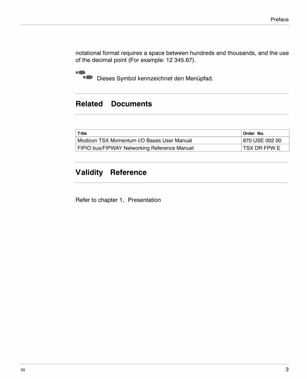
Dieses Symbol kennzeichnet den Menüpfad.
Related Documents
Title Order�No.
Modicon TSX Momentum I/O Bases User Manual 870 USE 002 00FIPIO bus/FIPWAY Networking Reference Manuel TSX DR FPW E
Validity Reference
Refer to chapter 1, ”Presentation”

Preface
204
Content
III20
Breite: 178 mmHöhe: 216 mm
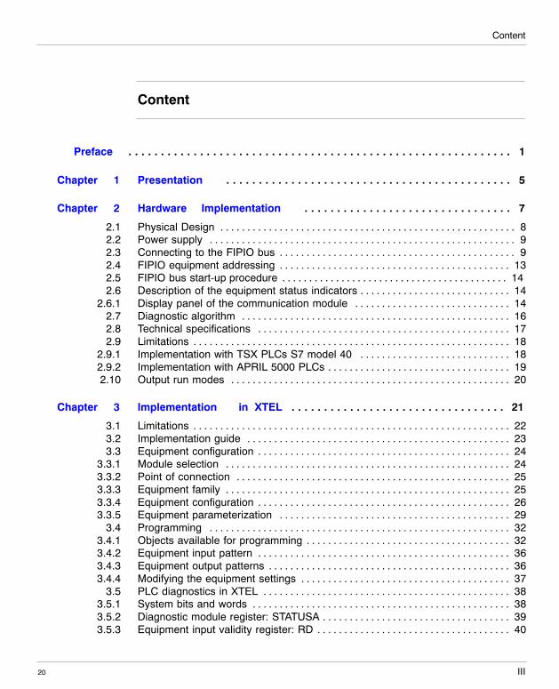
Content
Preface 1. . . . . . . . . . . . . . . . . . . . . . . . . . . . . . . . . . . . . . . . . . . . . . . . . . . . . . . . . . .
Chapter 1 Presentation 5. . . . . . . . . . . . . . . . . . . . . . . . . . . . . . . . . . . . . . . . . . . .
Chapter 2 Hardware Implementation 7. . . . . . . . . . . . . . . . . . . . . . . . . . . . . . . .
2.1 Physical Design 8. . . . . . . . . . . . . . . . . . . . . . . . . . . . . . . . . . . . . . . . . . . . . . . . . . . . . . .2.2 Power supply 9. . . . . . . . . . . . . . . . . . . . . . . . . . . . . . . . . . . . . . . . . . . . . . . . . . . . . . . . .2.3 Connecting to the FIPIO bus 9. . . . . . . . . . . . . . . . . . . . . . . . . . . . . . . . . . . . . . . . . . . .2.4 FIPIO equipment addressing 13. . . . . . . . . . . . . . . . . . . . . . . . . . . . . . . . . . . . . . . . . . .2.5 FIPIO bus start-up procedure 14. . . . . . . . . . . . . . . . . . . . . . . . . . . . . . . . . . . . . . . . . .2.6 Description of the equipment status indicators 14. . . . . . . . . . . . . . . . . . . . . . . . . . . .
2.6.1 Display panel of the communication module 14. . . . . . . . . . . . . . . . . . . . . . . . . . . . .2.7 Diagnostic algorithm 16. . . . . . . . . . . . . . . . . . . . . . . . . . . . . . . . . . . . . . . . . . . . . . . . . .2.8 Technical specifications 17. . . . . . . . . . . . . . . . . . . . . . . . . . . . . . . . . . . . . . . . . . . . . . .2.9 Limitations 18. . . . . . . . . . . . . . . . . . . . . . . . . . . . . . . . . . . . . . . . . . . . . . . . . . . . . . . . . . .
2.9.1 Implementation with TSX PLCs S7 model 40 18. . . . . . . . . . . . . . . . . . . . . . . . . . . .2.9.2 Implementation with APRIL 5000 PLCs 19. . . . . . . . . . . . . . . . . . . . . . . . . . . . . . . . . .2.10 Output run modes 20. . . . . . . . . . . . . . . . . . . . . . . . . . . . . . . . . . . . . . . . . . . . . . . . . . . .
Chapter 3 Implementation in XTEL 21. . . . . . . . . . . . . . . . . . . . . . . . . . . . . . . . .
3.1 Limitations 22. . . . . . . . . . . . . . . . . . . . . . . . . . . . . . . . . . . . . . . . . . . . . . . . . . . . . . . . . . .3.2 Implementation guide 23. . . . . . . . . . . . . . . . . . . . . . . . . . . . . . . . . . . . . . . . . . . . . . . . .3.3 Equipment configuration 24. . . . . . . . . . . . . . . . . . . . . . . . . . . . . . . . . . . . . . . . . . . . . . .
3.3.1 Module selection 24. . . . . . . . . . . . . . . . . . . . . . . . . . . . . . . . . . . . . . . . . . . . . . . . . . . . .3.3.2 Point of connection 25. . . . . . . . . . . . . . . . . . . . . . . . . . . . . . . . . . . . . . . . . . . . . . . . . . .3.3.3 Equipment family 25. . . . . . . . . . . . . . . . . . . . . . . . . . . . . . . . . . . . . . . . . . . . . . . . . . . . .3.3.4 Equipment configuration 26. . . . . . . . . . . . . . . . . . . . . . . . . . . . . . . . . . . . . . . . . . . . . . .3.3.5 Equipment parameterization 29. . . . . . . . . . . . . . . . . . . . . . . . . . . . . . . . . . . . . . . . . . .
3.4 Programming 32. . . . . . . . . . . . . . . . . . . . . . . . . . . . . . . . . . . . . . . . . . . . . . . . . . . . . . . .3.4.1 Objects available for programming 32. . . . . . . . . . . . . . . . . . . . . . . . . . . . . . . . . . . . . .3.4.2 Equipment input pattern 36. . . . . . . . . . . . . . . . . . . . . . . . . . . . . . . . . . . . . . . . . . . . . . .3.4.3 Equipment output patterns 36. . . . . . . . . . . . . . . . . . . . . . . . . . . . . . . . . . . . . . . . . . . . .3.4.4 Modifying the equipment settings 37. . . . . . . . . . . . . . . . . . . . . . . . . . . . . . . . . . . . . . .
3.5 PLC diagnostics in XTEL 38. . . . . . . . . . . . . . . . . . . . . . . . . . . . . . . . . . . . . . . . . . . . . .3.5.1 System bits and words 38. . . . . . . . . . . . . . . . . . . . . . . . . . . . . . . . . . . . . . . . . . . . . . . .3.5.2 Diagnostic module register: STATUSA 39. . . . . . . . . . . . . . . . . . . . . . . . . . . . . . . . . . .3.5.3 Equipment input validity register: RD 40. . . . . . . . . . . . . . . . . . . . . . . . . . . . . . . . . . . .
Content
20IV
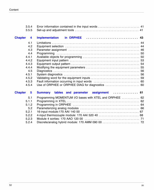
3.5.4 Error information contained in the input words 41. . . . . . . . . . . . . . . . . . . . . . . . . . . .3.5.5 Set-up and adjustment tools 41. . . . . . . . . . . . . . . . . . . . . . . . . . . . . . . . . . . . . . . . . . .
Chapter 4 Implementation in ORPHEE 43. . . . . . . . . . . . . . . . . . . . . . . . . . . . .
4.1 Limitations 44. . . . . . . . . . . . . . . . . . . . . . . . . . . . . . . . . . . . . . . . . . . . . . . . . . . . . . . . . . .4.2 Equipment selection 44. . . . . . . . . . . . . . . . . . . . . . . . . . . . . . . . . . . . . . . . . . . . . . . . . .4.3 Parameter assignment 46. . . . . . . . . . . . . . . . . . . . . . . . . . . . . . . . . . . . . . . . . . . . . . . .4.4 Programming 50. . . . . . . . . . . . . . . . . . . . . . . . . . . . . . . . . . . . . . . . . . . . . . . . . . . . . . . .
4.4.1 Available objects for programming 50. . . . . . . . . . . . . . . . . . . . . . . . . . . . . . . . . . . . . .4.4.2 Equipment input pattern 53. . . . . . . . . . . . . . . . . . . . . . . . . . . . . . . . . . . . . . . . . . . . . . .4.4.3 Equipment output pattern 54. . . . . . . . . . . . . . . . . . . . . . . . . . . . . . . . . . . . . . . . . . . . . .4.4.4 Modifying the equipment parameters 55. . . . . . . . . . . . . . . . . . . . . . . . . . . . . . . . . . . .
4.5 Diagnostics 56. . . . . . . . . . . . . . . . . . . . . . . . . . . . . . . . . . . . . . . . . . . . . . . . . . . . . . . . . .4.5.1 System diagnostics 56. . . . . . . . . . . . . . . . . . . . . . . . . . . . . . . . . . . . . . . . . . . . . . . . . . .4.5.2 Validating word for the equipment inputs 59. . . . . . . . . . . . . . . . . . . . . . . . . . . . . . . . .4.5.3 Fault information occurring in input words 60. . . . . . . . . . . . . . . . . . . . . . . . . . . . . . .4.5.4 Use of ORPHEE or ORPHEE DIAG for diagnostics 60. . . . . . . . . . . . . . . . . . . . . . .
Chapter 5 Summary tables and parameter assignment 61. . . . . . . . . . . . . .
5.1 Programming MOMENTUM I/O bases with XTEL and ORPHEE 62. . . . . . . . . . . .5.1.1 Programming in XTEL 62. . . . . . . . . . . . . . . . . . . . . . . . . . . . . . . . . . . . . . . . . . . . . . . . .5.1.2 Programming in ORPHEE 64. . . . . . . . . . . . . . . . . . . . . . . . . . . . . . . . . . . . . . . . . . . . .
5.2 Parameterizing analog modules 66. . . . . . . . . . . . . . . . . . . . . . . . . . . . . . . . . . . . . . . .5.2.1 16-input module:170 AAI 140 00 67. . . . . . . . . . . . . . . . . . . . . . . . . . . . . . . . . . . . . . .5.2.2 4-input thermocouple module: 170 AAI 520 40 68. . . . . . . . . . . . . . . . . . . . . . . . . . .5.2.3 Module 4 sorties: 170 AAO 120 00 71. . . . . . . . . . . . . . . . . . . . . . . . . . . . . . . . . . . . .5.2.4 Discrete/analog hybrid module: 170 AMM 090 00 72. . . . . . . . . . . . . . . . . . . . . . . . .
1
W idth: 178 mmHeight: 216 mm
20
Presentation
This documentation covers the use (implementation and operation) of the discreteand analog input/output interfaces of the MOMENTUM product line with PLCs viathe FIPIO bus.
The FIPIO 170 FNT 110 00 communication adapter lets you connect I/O bases ofthe MOMENTUM product family to the FIPIO bus. The FIPIO communicationadapter permits the connection of the MOMENTUM products to the followingPLCs:
PLC TSX Telecontroller model 40(version 5.5 and up)
APRIL CPU5030 and CPU5130(version 2 and up)
Software house XTEL V52 or V6 with disketteTXTRCTG V6 F
ORPHEE (version 6.2 minimum)
Operation of the MOMENTUM products with the XTEL software facility isdescribed in Chapter 3; operation of the MOMENTUM products at ORPHEE isdescribed in Chapter 4.
The following functionalities are available:
H I/O base parameter assignment (at start�up and in operation)H Managing cyclic input and output data exchangesH Processing diagnostic information
However, messaging operations are not available.
1
Presentation
202
In the course of these descriptions the following terms are used:
Communication adapterThis refers to the module which lets you connect to the FIPIO bus. The productnumber is 170 FNT 110 00.
I/O baseThis refers to the input/output module of the MOMENTUM family which connectsto the communication adapter.
Modulerefers to either the communication adapter or the I/O base.
EquipmentThis refers to a device, a functional assembly constituted of a communicationmodule connected to an I/O base.
Point of connectionaddress of equipment connected to the FIPIO bus

3
W idth: 178 mmHeight: 216 mm
20
Hardware Implementation
2
Hardware Implementation
204
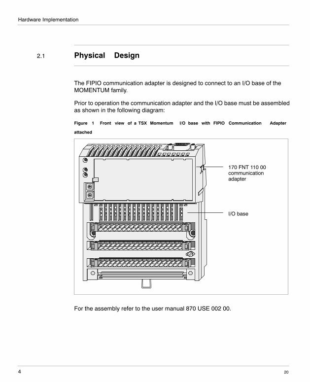
2.1 Physical Design
The FIPIO communication adapter is designed to connect to an I/O base of theMOMENTUM family.
Prior to operation the communication adapter and the I/O base must be assembledas shown in the following diagram:
Figure 1 Front view of a TSX Momentum I/O base with FIPIO Communication Adapter
attached
I/O base
170 FNT 110 00communicationadapter
For the assembly refer to the user manual 870 USE 002 00.
Hardware Implementation
5
W idth: 178 mmHeight: 216 mm
20
2.2 Power supply
Power is automatically supplied to the FIPIO communication adapter by the I/Obase to which it is connected. For specifications and power-supply wiringinstructions, refer to the I/O base set-up instructions (870 USE 002 00).
The 170 FNT 110 00 communication adapter is compatible with all I/O bases listedin the MOMENTUM catalog. It can be operated in conjunction with one I/O baseonly.
2.3 Connecting to the FIPIO bus
Several accessories are recommended to facilitate wiring the FIPIO bus:
H TSX FP ACC12 and TSX FP ACC2 connectors for connecting the equipmentto FIPIO
H TSX FP CA/CRxxx main cable, commercially available in lengths of 100, 200or 500 m
H TSX FP CCxxx drop cables commercially available in lengths of 100, 200 or500 m
H TSX FP ACC4 junction boxH TSX FP ACC7 line terminatorH TSX LES 65 or TSX LES 75 connector for connecting to Series 7 controllers
(PLCs), TSX models 40H KIT5130 power cord for connecting the APRIL 5000 PLC
When installing MOMENTUM modules in a cabinet, using the TSX FP ACC2connector for connecting to the FIPIO bus will permit optimal space utilization.
Hardware Implementation
206
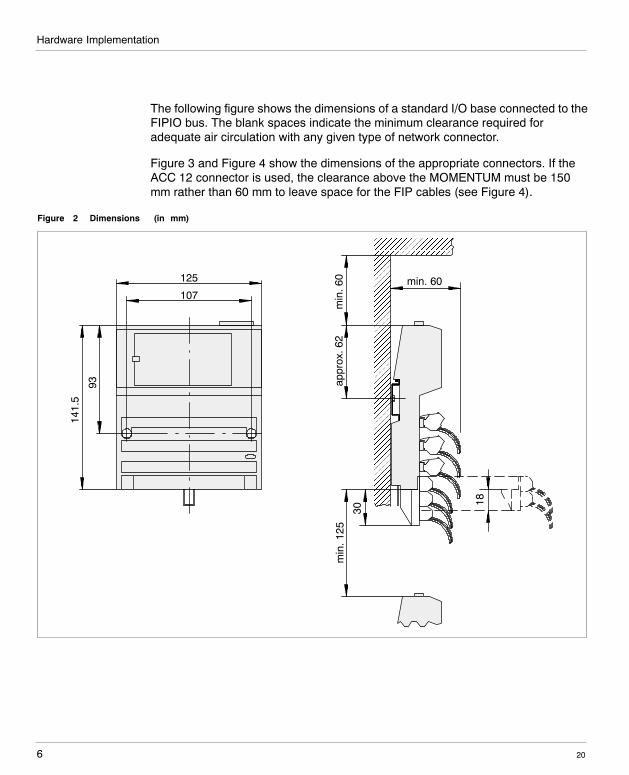
The following figure shows the dimensions of a standard I/O base connected to theFIPIO bus. The blank spaces indicate the minimum clearance required foradequate air circulation with any given type of network connector.
Figure 3 and Figure 4 show the dimensions of the appropriate connectors. If theACC 12 connector is used, the clearance above the MOMENTUM must be 150mm rather than 60 mm to leave space for the FIP cables (see Figure 4).
Figure 2 Dimensions (in mm)
min. 60
min
.125
appr
ox.6
2
93
141.
5
107
125
min
.60
30
18
Hardware Implementation
7
W idth: 178 mmHeight: 216 mm
20
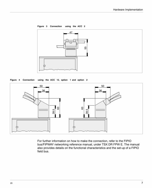
Figure 3 Connection using the ACC 2
47
55
Figure 4 Connection using the ACC 12, option 1 and option 2
39.5 63
36
5039
.563
36
50
For further information on how to make the connection, refer to the FIPIObus/FIPWAY networking reference manual, under TSX DR FPW E. The manualalso provides details on the functional characteristics and the set-up of a FIPIOfield bus.
Hardware Implementation
208
In addition, the ”ground wiring guide” TSX DG GND contains valuable installationdo’s and don’ts for the wiring of a FIPIO field bus.
CautionMake sure that for each line section the string of connectors is connected toprotective ground at least at one point.
Hardware Implementation
9
W idth: 178 mmHeight: 216 mm
20
2.4 FIPIO equipment addressing
Equipment on the FIPIO bus is identified by its point of connection. The number ofthe point of connection represents its physical address on the FIPIO bus and canbe a value between 1 and 62.
On the FIPIO, 0 is the address reserved for the PLC (TSX model 40 or APRIL5000) which is the bus manager. Address 63 is reserved for the programmingterminal.If an address number greater than 62 is entered into the communication adapter,the equipment will be neither recognized nor controlled by the PLC.
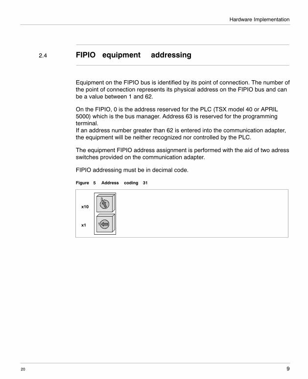
The equipment FIPIO address assignment is performed with the aid of two adressswitches provided on the communication adapter.
FIPIO addressing must be in decimal code.
Figure 5 Address coding 31
x10
x1
3
1
Hardware Implementation
2010
For changing an address, the equipment must first be powered down and thenpowered up again.
CautionIf the address is changed with the power on, it will cause an internal errorand disconnection of the FIPIO bus.
ST OP
W arningTwo equipment units on the FIPIO bus must never have the same address.When three LEDs (RUN, ERR, COM) keep blinking simultaneously , itindicates that the equipment cannot establish the connection to the FIPIObus because its address is already occupied by another device.
2.5 FIPIO bus start�up procedure
It is recommended that the equipment devices be brought on line one after theother. For a detailed description of the initial start�up of an application on FIPIO,refer to the FIPIO bus/FIPWAY network reference manual under TSX DR FPW E.
2.6 Description of the equipment status indicators
2.6.1 Display panel of the communication module
The FIPIO communication adapter of the MOMENTUM family features a displaypanel with three status indicators (RUN, ERR, COM) showing its operating status.
ST OP
Hardware Implementation
11
W idth: 178 mmHeight: 216 mm
20
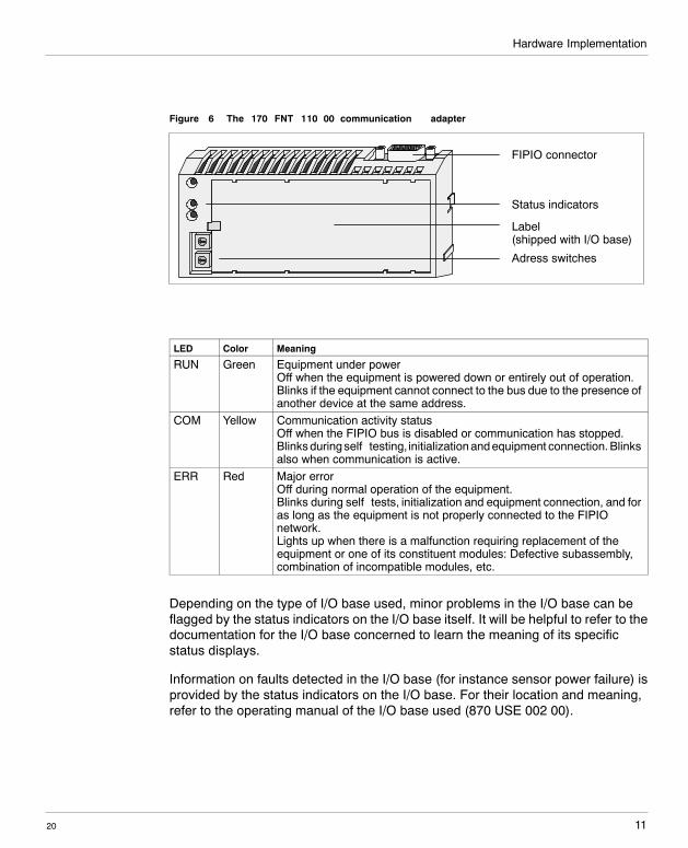
Figure 6 The 170 FNT 110 00 communication adapter
FIPIO connector
Status indicators
Label(shipped with I/O base)
Adress switches
LED Color Meaning
RUN Green Equipment under powerOff when the equipment is powered down or entirely out of operation.Blinks if the equipment cannot connect to the bus due to the presence ofanother device at the same address.
COM Yellow Communication activity statusOff when the FIPIO bus is disabled or communication has stopped.Blinks during self�testing, initialization and equipment connection. Blinksalso when communication is active.
ERR Red Major errorOff during normal operation of the equipment.Blinks during self�tests, initialization and equipment connection, and foras long as the equipment is not properly connected to the FIPIOnetwork.Lights up when there is a malfunction requiring replacement of theequipment or one of its constituent modules: Defective subassembly,combination of incompatible modules, etc.
Depending on the type of I/O base used, minor problems in the I/O base can beflagged by the status indicators on the I/O base itself. It will be helpful to refer to thedocumentation for the I/O base concerned to learn the meaning of its specificstatus displays.
Information on faults detected in the I/O base (for instance sensor power failure) isprovided by the status indicators on the I/O base. For their location and meaning,refer to the operating manual of the I/O base used (870 USE 002 00).
Hardware Implementation
2012
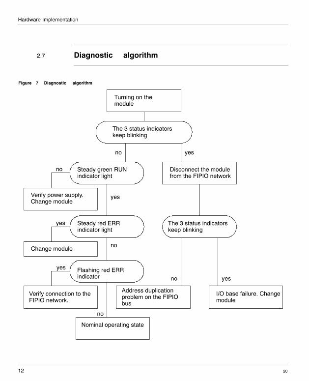
2.7 Diagnostic algorithm
Figure 7 Diagnostic algorithm
Turning on themodule
The 3 status indicatorskeep blinking
Disconnect the modulefrom the FIPIO network
yesno
Steady green RUNindicator light
Steady red ERRindicator light
yes
Flashing red ERRindicator
The 3 status indicatorskeep blinking
yesno
I/O base failure. Changemodule
Address duplicationproblem on the FIPIObus
no
yes
yes
no
Verify power supply.Change module
Change module
Verify connection to theFIPIO network.
no
Nominal operating state
Hardware Implementation
13
W idth: 178 mmHeight: 216 mm
20
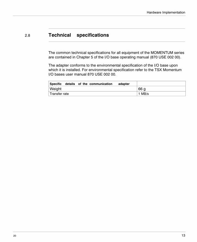
2.8 Technical specifications
The common technical specifications for all equipment of the MOMENTUM seriesare contained in Chapter 5 of the I/O base operating manual (870 USE 002 00).
The adapter conforms to the environmental specification of the I/O base uponwhich it is installed. For environmental specification refer to the TSX MomentumI/O bases user manual 870 USE 002 00.
Specific details of the communication adapter
Weight 66 gTransfer rate 1 MB/s
Hardware Implementation
2014
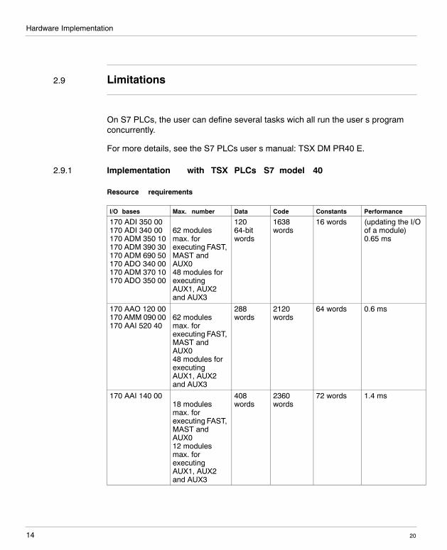
2.9 Limitations
On S7 PLCs, the user can define several tasks wich all run the user’s programconcurrently.
For more details, see the S7 PLCs user’s manual: TSX DM PR40 E.
2.9.1 Implementation with TSX PLCs S7 model 40
Resource requirements
I/O bases Max. number Data Code Constants Performance
170 ADI 350 00170 ADI 340 00170 ADM 350 10170 ADM 390 30170 ADM 690 50170 ADO 340 00170 ADM 370 10170 ADO 350 00
62 modulesmax. forexecuting FAST,MAST andAUX048 modules forexecutingAUX1, AUX2and AUX3
12064-bitwords
1638words
16 words (updating the I/Oof a module)0.65 ms
170 AAO 120 00170 AMM 090 00170 AAI 520 40
62 modulesmax. forexecuting FAST,MAST andAUX048 modules forexecutingAUX1, AUX2and AUX3
288words
2120words
64 words 0.6 ms
170 AAI 140 0018 modulesmax. forexecuting FAST,MAST andAUX012 modulesmax. forexecutingAUX1, AUX2and AUX3
408words
2360words
72 words 1.4 ms
Hardware Implementation
15
W idth: 178 mmHeight: 216 mm
20
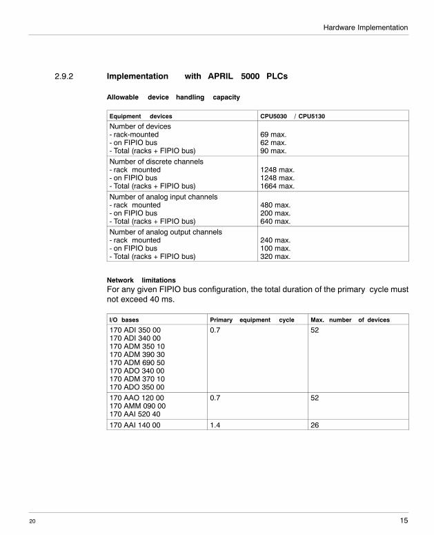
2.9.2 Implementation with APRIL 5000 PLCs
Allowable device handling capacity
Equipment devices CPU5030 / CPU5130
Number of devices- rack-mounted- on FIPIO bus- Total (racks + FIPIO bus)
69 max.62 max.90 max.
Number of discrete channels- rack�mounted- on FIPIO bus- Total (racks + FIPIO bus)
1248 max.1248 max.1664 max.
Number of analog input channels- rack�mounted- on FIPIO bus- Total (racks + FIPIO bus)
480 max.200 max.640 max.
Number of analog output channels- rack�mounted- on FIPIO bus- Total (racks + FIPIO bus)
240 max.100 max.320 max.
Network limitationsFor any given FIPIO bus configuration, the total duration of the primary cycle mustnot exceed 40 ms.
I/O bases Primary equipment cycle Max. number of devices
170 ADI 350 00170 ADI 340 00170 ADM 350 10170 ADM 390 30170 ADM 690 50170 ADO 340 00170 ADM 370 10170 ADO 350 00
0.7 52
170 AAO 120 00170 AMM 090 00170 AAI 520 40
0.7 52
170 AAI 140 00 1.4 26
Hardware Implementation
2016
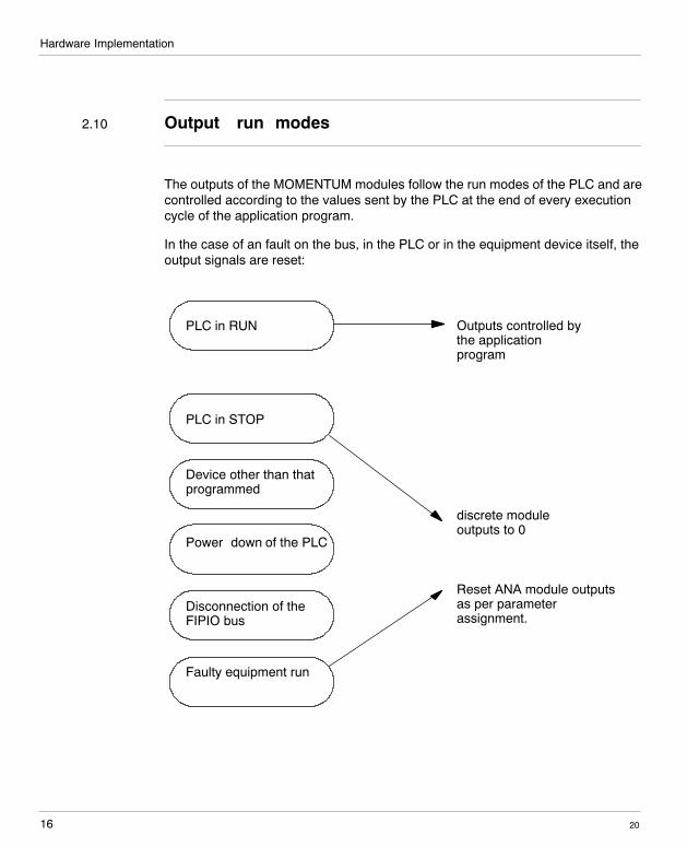
2.10 Output run modes
The outputs of the MOMENTUM modules follow the run modes of the PLC and arecontrolled according to the values sent by the PLC at the end of every executioncycle of the application program.
In the case of an fault on the bus, in the PLC or in the equipment device itself, theoutput signals are reset:
PLC in RUN
PLC in STOP
Device other than thatprogrammed
Power�down of the PLC
Disconnection of theFIPIO bus
Faulty equipment run
discrete moduleoutputs to 0
Outputs controlled bythe applicationprogram
Reset ANA module outputsas per parameterassignment.

17
W idth: 178 mmHeight: 216 mm
20
Implementation in XTEL
3
Implementation in XTEL
2018
3.1 Limitations
Configuring, programming and diagnosing MOMENTUM equipment devices on theFIPIO bus using the XTEL-CONF tool can be accomplished with:
H XTEL V52,H XTEL V6 (and PL7�3 V6)
if the diskette TXT LF CTG TSXM V6 has been installed (belongs to theproduct TXTRCTG V6 E).
Operating MOMENTUM equipment is possible only with versions V5.5 and higheron S7 processors TSX model 40.
TSX MOMENTUM modules are not operable with PMS2.
Implementation in XTEL
19
W idth: 178 mmHeight: 216 mm
20
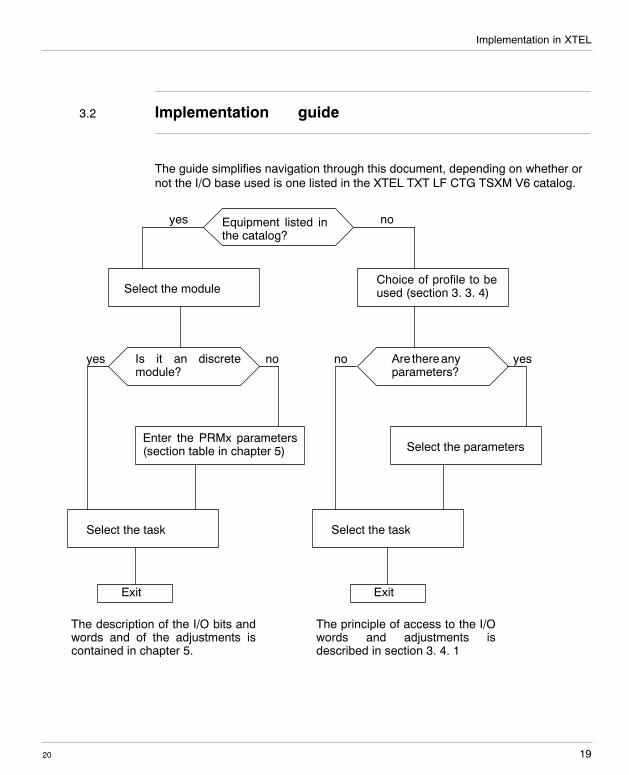
3.2 Implementation guide
The guide simplifies navigation through this document, depending on whether ornot the I/O base used is one listed in the XTEL TXT LF CTG TSXM V6 catalog.
Equipment listed inthe catalog?
Select the module
Is it an discretemodule?
Choice of profile to beused (section 3. 3. 4)
yes no
yes no
Enter the PRMx parameters(section table in chapter 5)
Select the task
Are thereanyparameters?
no yes
ExitExit
The description of the I/O bits andwords and of the adjustments iscontained in chapter 5.
The principle of access to the I/Owords and adjustments isdescribed in section 3. 4. 1
Select the task
Select the parameters
Implementation in XTEL
2020
3.3 Equipment configuration
3.3.1 Module selection
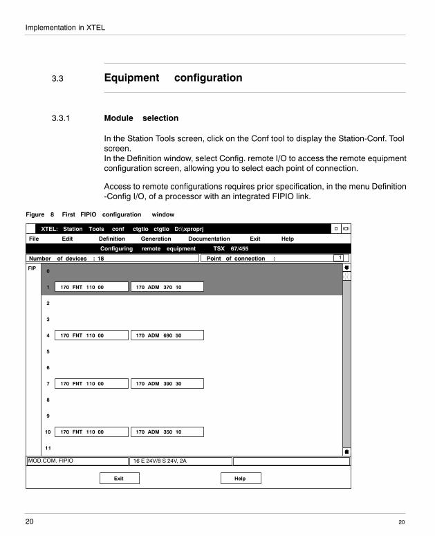
In the Station Tools screen, click on the Conf tool to display the Station-Conf. Toolscreen.In the Definition window, select Config. remote I/O to access the remote equipmentconfiguration screen, allowing you to select each point of connection.
Access to remote configurations requires prior specification, in the menu Definition-Config I/O, of a processor with an integrated FIPIO link.
Figure 8 First FIPIO configuration window
16 E 24V/8 S 24V, 2A
XTEL: Station Tools �conf� ctgtio ctgtio D:\\xproprj
File Edit Definition Generation Documentation Exit Help
MOD.COM. FIPIO
Configuring remote equipment � TSX 67/455
Number of devices : 18 Point of connection :
FIP 0
1
2
3
4
5
6
7
8
9
10
11
170 FNT 110 00
170 FNT 110 00
170 FNT 110 00
170 FNT 110 00
1
170 ADM 690 50
170 ADM 390 30
170 ADM 350 10
170 ADM 370 10
HelpExit
Implementation in XTEL
21
W idth: 178 mmHeight: 216 mm
20
The screen is subdivided into 64 zones numbered 0 to 63. Each zone represents apoint of connection in the FIPIO network and can be occupied by a device, with theexception of zones 0 and 63 which are respectively reserved for the PLC and theprogramming terminal. The number of the point of connection of a device can beone between 1 and 62.
3.3.2 Point of connection
The number of the point of connection defined as XTEL must be identical to theaddress assigned by means of the code wheels on the FIPIO communicationadapter.Use the arrow keys or the mouse pointer to select the point of connection. Thenumber of the point of connection is now highlighted. To access the FIPIOconfiguration, press the ENTER key or double�click on the highlighted line.
3.3.3 Equipment family
The MOMENTUM equipment family is available only after loading the diskette cat.# TXT LF CTG TSXM V6.
Implementation in XTEL
2022
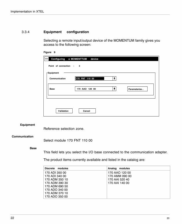
3.3.4 Equipment configuration
Selecting a remote input/output device of the MOMENTUM family gives youaccess to the following screen:
Figure 9
Cancel
170 FNT 110 00
Configuring a MOMENTTUM device
Communication
Point of connection : 3
Validation
Equipment
170 AAO 120 00Base Parameterize...
EquipmentReference selection zone.
CommunicationSelect module 170 FNT 110 00
BaseThis field lets you select the I/O base connected to the communication adapter.
The product items currently available and listed in the catalog are:
Discrete modules Analog modules
170 ADI 350 00170 ADI 340 00170 ADM 350 10170 ADM 390 30170 ADM 690 50170 ADO 340 00170 ADM 370 10170 ADO 350 00
170 AAO 120 00170 AMM 090 00170 AAI 520 40170 AAI 140 00
Implementation in XTEL
23
W idth: 178 mmHeight: 216 mm
20
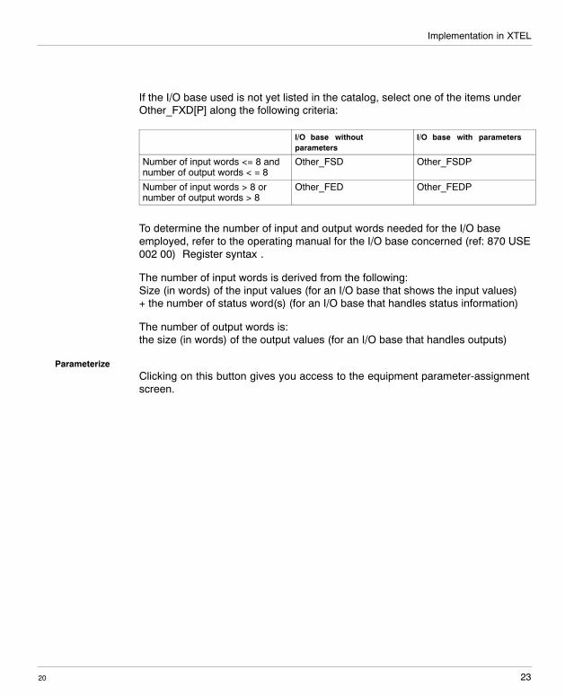
If the I/O base used is not yet listed in the catalog, select one of the items underOther_FXD[P] along the following criteria:
I/O base withoutparameters
I/O base with parameters
Number of input words <= 8 andnumber of output words < = 8
Other_FSD Other_FSDP
Number of input words > 8 ornumber of output words > 8
Other_FED Other_FEDP
To determine the number of input and output words needed for the I/O baseemployed, refer to the operating manual for the I/O base concerned (ref: 870 USE002 00) ”Register syntax”.
The number of input words is derived from the following:Size (in words) of the input values (for an I/O base that shows the input values)+ the number of status word(s) (for an I/O base that handles status information)
The number of output words is:the size (in words) of the output values (for an I/O base that handles outputs)
ParameterizeClicking on this button gives you access to the equipment parameter-assignmentscreen.
Implementation in XTEL
2024
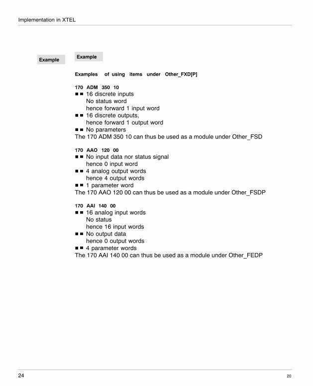
Example
Examples of using items under Other_FXD[P]
170 ADM 350 10H 16 discrete inputs
No status wordhence forward 1 input word
H 16 discrete outputs,hence forward 1 output word
H No parametersThe 170 ADM 350 10 can thus be used as a module under Other_FSD
170 AAO 120 00H No input data nor status signal
hence 0 input wordH 4 analog output words
hence 4 output wordsH 1 parameter wordThe 170 AAO 120 00 can thus be used as a module under Other_FSDP
170 AAI 140 00H 16 analog input words
No statushence 16 input words
H No output datahence 0 output words
H 4 parameter wordsThe 170 AAI 140 00 can thus be used as a module under Other_FEDP
Example
Implementation in XTEL
25
W idth: 178 mmHeight: 216 mm
20
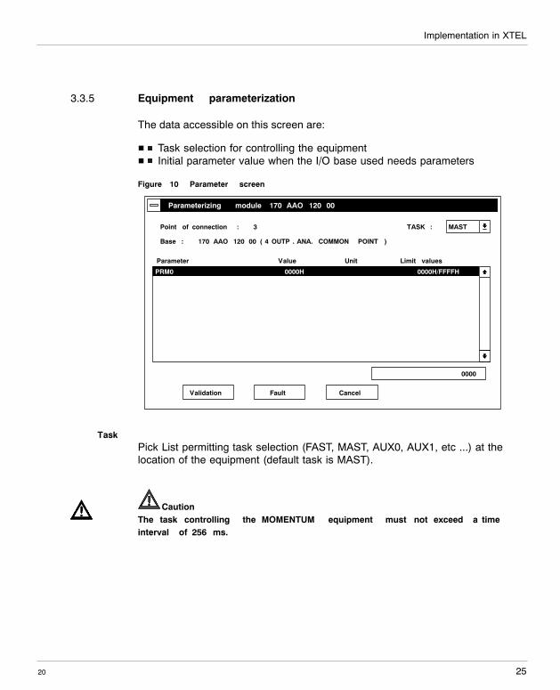
3.3.5 Equipment parameterization
The data accessible on this screen are:
H Task selection for controlling the equipmentH Initial parameter value when the I/O base used needs parameters
Figure 10 Parameter screen
Parameterizing module 170 AAO 120 00
MASTTASK :Point of connection : 3
Base : 170 AAO 120 00 ( 4 OUTP . ANA. COMMON POINT )
PRM0 0000H 0000H/FFFFH
Parameter Value Unit Limit values
0000
Validation Fault Cancel
TaskPick List permitting task selection (FAST, MAST, AUX0, AUX1, etc ...) at thelocation of the equipment (default task is MAST).
CautionThe task controlling the MOMENTUM equipment must not exceed a timeinterval of 256 ms.
Implementation in XTEL
2026
ParametersH PRM 0 to PRM 31 (or PRM29) are the control parameters for the I/O base to
which the communication adapter is connected.
Refer to the documentation for the I/O base used for information on the necessarynumber of parameter words, a description of the values as well as the order inwhich the words are to be entered, (the first parameter word should be entered inPRM0).
CautionThe PRMxx words which are not used by the I/O base must absolutely be leftat a value of 0.
CautionThere are no default settings for these parameters. Thus specific parametervalues must be supplied by the user for all PRMxx words presented by thesoftware.
Also refer to the table in Chapter 5 which specifies for each MOMENTUM I/O baselisted in the XTEL catalog how the parameter words should be entered.
ValueCurrent parameter value displayed in hexadecimal.
UnitNot significant.
Limit valuesMinimum/maximum value range allowable for the parameter concerned: 1 -FFFEh for equipment of the MOMENTUM family.
DefaultThis button assiggns the MAST value to the task that controls the equipment andinitializes at 0 the parameters and PRMxx.
Implementation in XTEL
27
W idth: 178 mmHeight: 216 mm
20
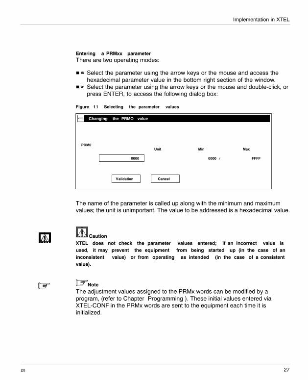
Entering a PRMxx parameterThere are two operating modes:
H Select the parameter using the arrow keys or the mouse and access thehexadecimal parameter value in the bottom right section of the window.
H Select the parameter using the arrow keys or the mouse and double-click, orpress ENTER, to access the following dialog box:
Figure 11 Selecting the parameter values
Cancel
Changing the PRMO value
PRM0MinUnit Max
0000
Validation
0000 / FFFF
The name of the parameter is called up along with the minimum and maximumvalues; the unit is unimportant. The value to be addressed is a hexadecimal value.
CautionXTEL does not check the parameter values entered; if an incorrect value isused, it may prevent the equipment from being started up (in the case of aninconsistent value) or from operating as intended (in the case of a consistentvalue).
NoteThe adjustment values assigned to the PRMx words can be modified by aprogram, (refer to Chapter ”Programming”). These initial values entered viaXTEL-CONF in the PRMx words are sent to the equipment each time it isinitialized.
Implementation in XTEL
2028
3.4 Programming
3.4.1 Objects available for programming
Access by the user to the inputs of the MOMENTUM equipment, allocation of itsoutputs and modification of its adjustment parameters are accomplished by way ofthe different registers which are directly operable within the PLC program. Accessto these registers requires correlating the configuration (established underXTEL-CONF) with PL7-3 by an appropriate reconfiguration operation. This isinitiated in PL7-3 using the V5CONF button for XTEL V52 and the XTEL-CONFTools/Feedback Function menu for the XTEL V6.
The following tables explain the mnemonics of the objects available for theapplication.
I/O base of the discrete typeThe program accesses the input bits with the following syntax:
Channels 1 to 16:
RIAx,0,yx = address of the equipment on the FIPIO bus: 1 to 62 in decimal0 = module number: always 0y = position of the bit in the channel: 0 to 15
Channels 17 to 32:
RIBx,0,yx = address of the equipment on the FIPIO bus: 1 to 62 in decimal0 = module number: always 0y = position of the bit in the channel: 0 to 15
The syntax is the same for the output bits: ROAx,0,y and ROBx,0,y
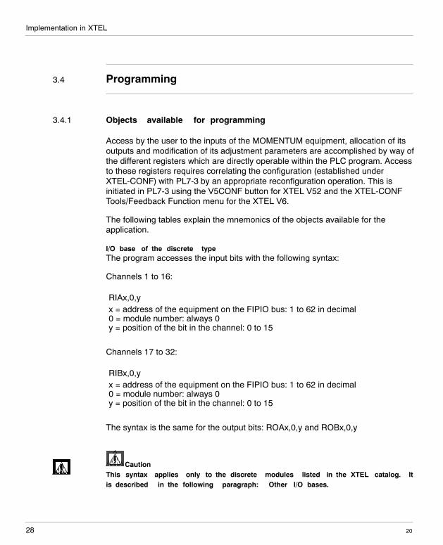
CautionThis syntax applies only to the discrete modules listed in the XTEL catalog. Itis described in the following paragraph: Other I/O bases.
Implementation in XTEL
29
W idth: 178 mmHeight: 216 mm
20
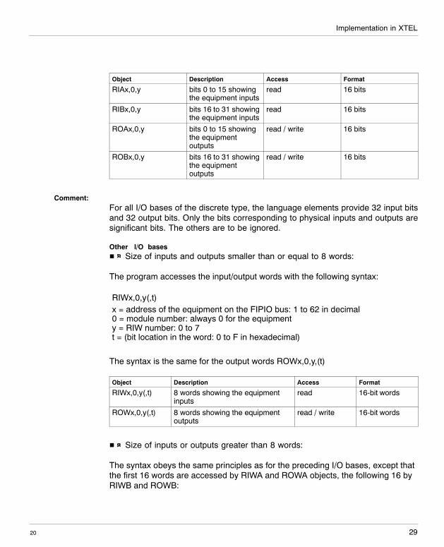
Object Description Access Format
RIAx,0,y bits 0 to 15 showingthe equipment inputs
read 16 bits
RIBx,0,y bits 16 to 31 showingthe equipment inputs
read 16 bits
ROAx,0,y bits 0 to 15 showingthe equipmentoutputs
read / write 16 bits
ROBx,0,y bits 16 to 31 showingthe equipmentoutputs
read / write 16 bits
Comment:For all I/O bases of the discrete type, the language elements provide 32 input bitsand 32 output bits. Only the bits corresponding to physical inputs and outputs aresignificant bits. The others are to be ignored.
Other I/O basesH Size of inputs and outputs smaller than or equal to 8 words:
The program accesses the input/output words with the following syntax:
RIWx,0,y(,t)x = address of the equipment on the FIPIO bus: 1 to 62 in decimal0 = module number: always 0 for the equipmenty = RIW number: 0 to 7t = (bit location in the word: 0 to F in hexadecimal)
The syntax is the same for the output words ROWx,0,y,(t)
Object Description Access Format
RIWx,0,y(,t) 8 words showing the equipmentinputs
read 16-bit words
ROWx,0,y(,t) 8 words showing the equipmentoutputs
read / write 16-bit words
H Size of inputs or outputs greater than 8 words:
The syntax obeys the same principles as for the preceding I/O bases, except thatthe first 16 words are accessed by RIWA and ROWA objects, the following 16 byRIWB and ROWB:
Implementation in XTEL
2030
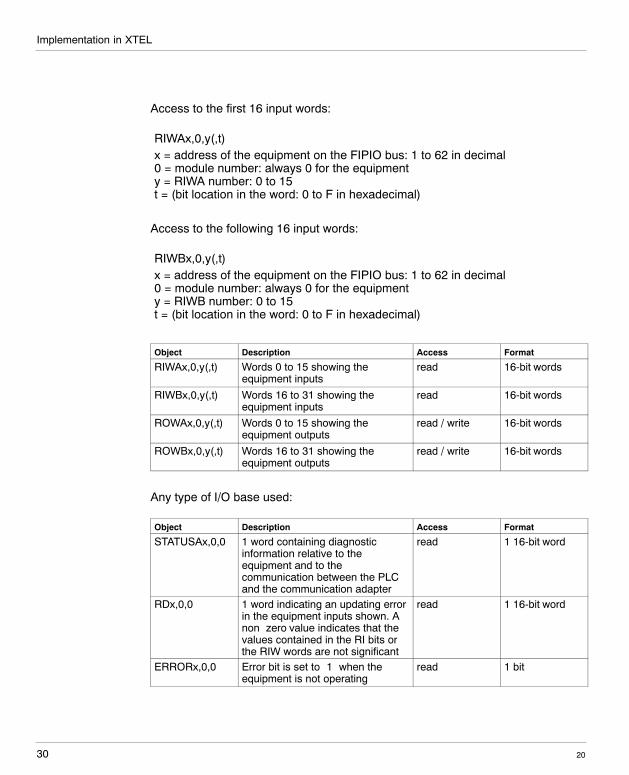
Access to the first 16 input words:
RIWAx,0,y(,t)x = address of the equipment on the FIPIO bus: 1 to 62 in decimal0 = module number: always 0 for the equipmenty = RIWA number: 0 to 15t = (bit location in the word: 0 to F in hexadecimal)
Access to the following 16 input words:
RIWBx,0,y(,t)x = address of the equipment on the FIPIO bus: 1 to 62 in decimal0 = module number: always 0 for the equipmenty = RIWB number: 0 to 15t = (bit location in the word: 0 to F in hexadecimal)
Object Description Access Format
RIWAx,0,y(,t) Words 0 to 15 showing theequipment inputs
read 16-bit words
RIWBx,0,y(,t) Words 16 to 31 showing theequipment inputs
read 16-bit words
ROWAx,0,y(,t) Words 0 to 15 showing theequipment outputs
read / write 16-bit words
ROWBx,0,y(,t) Words 16 to 31 showing theequipment outputs
read / write 16-bit words
Any type of I/O base used:
Object Description Access Format
STATUSAx,0,0 1 word containing diagnosticinformation relative to theequipment and to thecommunication between the PLCand the communication adapter
read 1 16-bit word
RDx,0,0 1 word indicating an updating errorin the equipment inputs shown. Anon�zero value indicates that thevalues contained in the RI bits orthe RIW words are not significant
read 1 16-bit word
ERRORx,0,0 Error bit is set to ”1” when theequipment is not operating
read 1 bit
Implementation in XTEL
31
W idth: 178 mmHeight: 216 mm
20
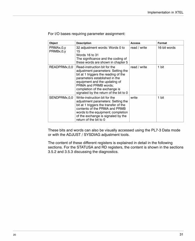
For I/O bases requiring parameter assignment:
Object Description Access Format
PRMAx,0,yPRMBx,0,y
32 adjustment words: Words 0 to15Words 16 to 31The significance and the coding ofthese words are shown in chapter 5
read / write 16-bit words
READPRMx,0,0 Read-instruction bit for theadjustment parameters: Setting thebit at 1 triggers the reading of theparameters established in theequipment and the updating ofPRMA and PRMB words;completion of the exchange issignaled by the return of the bit to 0
read / write 1 bit
SENDPRMx,0,0 Write-instruction bit for theadjustment parameters: Setting thebit at 1 triggers the transfer of thecontents of the PRMA and PRMBwords to the equipment; completionof the exchange is signaled by thereturn of the bit to 0
write 1 bit
These bits and words can also be visually accessed using the PL7-3 Data modeor with the ADJUST / SYSDIAG adjustment tools.
The content of these different registers is explained in detail in the followingsections. For the STATUSA and RD registers, the content is shown in the sections3.5.2 and 3.5.3 discussing the diagnostics.
Implementation in XTEL
2032
3.4.2 Equipment input pattern
The PLC provides the cyclic refresh rate for all inputs (RIA, RIB, RIW, RIWA,RIWB) at the start of the programming task involving the equipment.
The distribution of the data in the input words depends on the I/O base used, alongthe following principles:
H If the I/O base used shows status information, that will follow the inputvalues.
H If the total amount of input information (status + input values) is less than 8or 32 words, the remaining words are automatically forced to 0.
Chapter 5 contains a table which specifies for each MOMENTUM I/O base listed inthe XTEL catalog the order and significance of the input and output data.
Each word or bit in a word can be represented by its physical address or by asymbolic name, which must be predefined using the SDBASE XTEL station tool.
NoteThe input pattern words and bits contain significant values only if the diagnosticRD word equals 0. In all other cases the words should not be interpreted by thePLC program. Refer to the paragraph ”Diagnostics” for the list of possible values ofthe RD word.
3.4.3 Equipment output patterns
The PLC provides a cyclic refresh rate for all outputs (ROA, ROB, ROW, ROWA,ROWB) upon execution of the program task involving the equipment.
The data distribution in the output words depends on the I/O base used
If the total amount of output information is less than 8 or 32 words, the remainingwords are not significant and are not transmitted to the I/O base module by thecommunication adapter.
Chapter 5 contains a table which specifies for each MOMENTUM I/O base listed inthe XTEL catalog the order and significance of the input and output data.
Each word or bit in a word can be represented by its physical address or by asymbolic name, which must be predefined using the SDBASE XTEL station tool.
Implementation in XTEL
33
W idth: 178 mmHeight: 216 mm
20
3.4.4 Modifying the equipment settings
The equipment adjustment parameters are read- and write-accessible via thePLC program in these PRMAx,0,y and PRMBx,0,y words:
PRMAx,0,yx = address of the equipment on the FIPIO bus: 1 to 62 in decimal0 = module number: always 0y = adjustment�parameter number: 0 to F
Chapter 5 contains a table which specifies for each MOMENTUM I/O base listed inthe XTEL catalog how the adjustment words are to be used.
Setting the READPRM bit at 1 allows the equipment adjustment parameters to beread; upon completion of the exchange the bit returns to 0: The data present in thePRMAx,0,y and PRMBx,0,y words will now contain the equipment adjustmentvalues thus read.
Setting the SENDPRM bit at 1 allows the values contained in the PRMAx,0,y andPRMBx,0,y words to be transmitted to the equipment; upon completion of theexchange the bit returns to 0.
If the adjustment values transmitted have been rejected by the equipment, theApplication Default bit of the STATUS A register is set. The equipment continues tooperate with the last valid adjustment values received.
Implementation in XTEL
2034
3.5 PLC diagnostics in XTEL
3.5.1 System bits and words
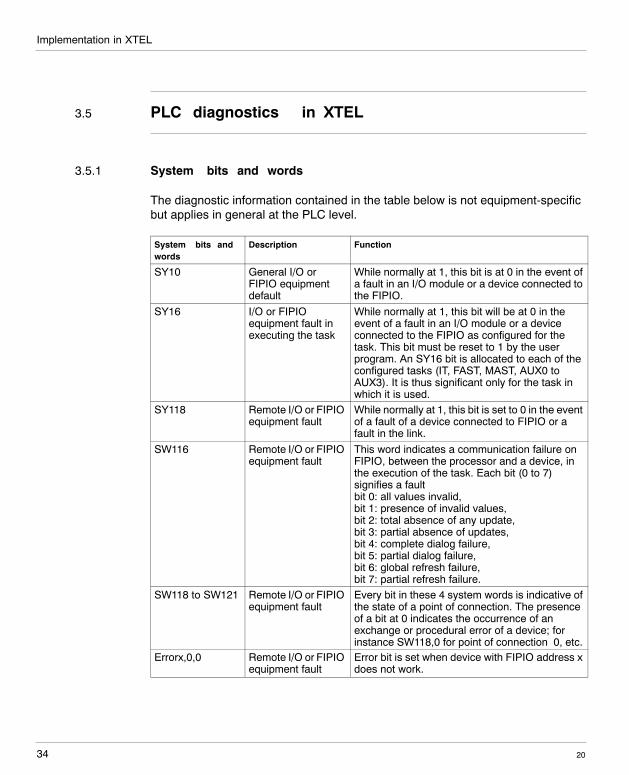
The diagnostic information contained in the table below is not equipment-specificbut applies in general at the PLC level.
System bits andwords
Description Function
SY10 General I/O orFIPIO equipmentdefault
While normally at 1, this bit is at 0 in the event ofa fault in an I/O module or a device connected tothe FIPIO.
SY16 I/O or FIPIOequipment fault inexecuting the task
While normally at 1, this bit will be at 0 in theevent of a fault in an I/O module or a deviceconnected to the FIPIO as configured for thetask. This bit must be reset to 1 by the userprogram. An SY16 bit is allocated to each of theconfigured tasks (IT, FAST, MAST, AUX0 toAUX3). It is thus significant only for the task inwhich it is used.
SY118 Remote I/O or FIPIOequipment fault
While normally at 1, this bit is set to 0 in the eventof a fault of a device connected to FIPIO or afault in the link.
SW116 Remote I/O or FIPIOequipment fault
This word indicates a communication failure onFIPIO, between the processor and a device, inthe execution of the task. Each bit (0 to 7)signifies a faultbit 0: all values invalid,bit 1: presence of invalid values,bit 2: total absence of any update,bit 3: partial absence of updates,bit 4: complete dialog failure,bit 5: partial dialog failure,bit 6: global refresh failure,bit 7: partial refresh failure.
SW118 to SW121 Remote I/O or FIPIOequipment fault
Every bit in these 4 system words is indicative ofthe state of a point of connection. The presenceof a bit at 0 indicates the occurrence of anexchange or procedural error of a device; forinstance SW118,0 for point of connection 0, etc.
Errorx,0,0 Remote I/O or FIPIOequipment fault
Error bit is set when device with FIPIO address xdoes not work.
Implementation in XTEL
35
W idth: 178 mmHeight: 216 mm
20
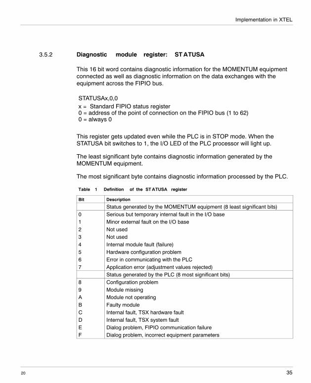
3.5.2 Diagnostic module register: ST ATUSA
This 16 bit word contains diagnostic information for the MOMENTUM equipmentconnected as well as diagnostic information on the data exchanges with theequipment across the FIPIO bus.
STATUSAx,0,0x = Standard FIPIO status register0 = address of the point of connection on the FIPIO bus (1 to 62)0 = always 0
This register gets updated even while the PLC is in STOP mode. When theSTATUSA bit switches to 1, the I/O LED of the PLC processor will light up.
The least significant byte contains diagnostic information generated by theMOMENTUM equipment.
The most significant byte contains diagnostic information processed by the PLC.
Table 1 Definition of the ST ATUSA register
Bit Description
Status generated by the MOMENTUM equipment (8 least significant bits)0 Serious but temporary internal fault in the I/O base1 Minor external fault on the I/O base2 Not used3 Not used4 Internal module fault (failure)5 Hardware configuration problem6 Error in communicating with the PLC7 Application error (adjustment values rejected)
Status generated by the PLC (8 most significant bits)8 Configuration problem9 Module missingA Module not operatingB Faulty moduleC Internal fault, TSX hardware faultD Internal fault, TSX system faultE Dialog problem, FIPIO communication failureF Dialog problem, incorrect equipment parameters
Implementation in XTEL
2036
Serious but tempotary internal fault in the I/O base (bit 0)When this bit appears, a transient disturbance affects the performance of the I/Obase connected to the communication adapter (for instance electromagneticinterference). As soon as that problem disappears, the equipment resumes normaloperation.
Minor external problem on the I/O base (bit 1)When this bit appears, an external problem exists on the I/O base used; the natureof the problem depends on the I/O base itself. You should therefore refer to thedocumentation for the I/O base used to determine which type of fault condition canbe flagged in the application program by the I/O error signal for the type of I/O baseconcerned (e.g. short�circuits etc.).
3.5.3 Equipment input validity register: RD
This 16 bit word indicates an error that occurred when the input patterns of theMOMENTUM equipment were being updated.If RD equals 0, the input values of the equipment are valid and can be used by thePLC program.
The most significant RD byte is generated by the MOMENTUM equipment duringinput acquisition.
The possible values of this byte are as follows:
H 0: The input values are suitable for use by the program (if the least significantbyte also equals 0)
H FFh: The equipment is inoperative; the input values are not usable for theprogram
H 01: A minor external problem exists on the I/O base; the input values cannotbe used by the program
H 02: A serious temporary fault exists in the I/O base; the input values cannotbe used by the program
The least significant RD byte is generated by the PLC processor. It relates to thecyclic updating of the inputs across the FIPIO bus. If it is other than zero, thevariable input patterns may contain old and incorrect values and must be ignoredby the application.
The RD register and the input pattern words are not updated when the PLC is inSTOP mode: They will retain their last value.
Implementation in XTEL
37
W idth: 178 mmHeight: 216 mm
20
3.5.4 Error information contained in the input words
Depending on the type of I/O base used, certain fault-related information can bereflected in the input data of the equipment.You should refer to your I/O base documentation to determine whether the I/Obase used displays status information or whether certain faults are indicated by thevalues outside the input range.
3.5.5 Set�up and adjustment tools
The SYSDIAG and ADJUST tools of the software house XTEL can be used for thediagnostics and the adjustment of the MOMENTUM equipment. They areemployed in the same way as for any other FIPIO equipment. Refer to the XTELdocumentation for further details on this subject.

Implementation in XTEL
2038

39
W idth: 178 mmHeight: 216 mm
20
Implementation in ORPHEE
4
Implementation in ORPHEE
2040
4.1 Limitations
The ORPHEE configuration editor permits the connection and configuration ofequipment devices on the FIPIO bus. The configuration of a MOMENTUM devicerequires an ORPHEE version >= 6.2.The following paragraphs describe the operating mode that permits the use of aMOMENTUM device on the FIPIO bus controlled by APRIL 5000.For further details on the principles of connecting and configuring equipment onthe FIPIO bus, refer to the documentation titled ”ORPHEE/ORPHEE-DIAGadjunct” for using the FIPIO bus with APRIL 5000” ref. TEM10000/10800E.Operating MOMENTUM equipment is possible with version 2 or higher of theS1000 CPU5030 and S1000 CPU5130 processors.
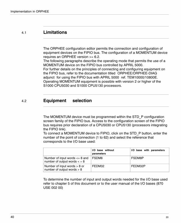
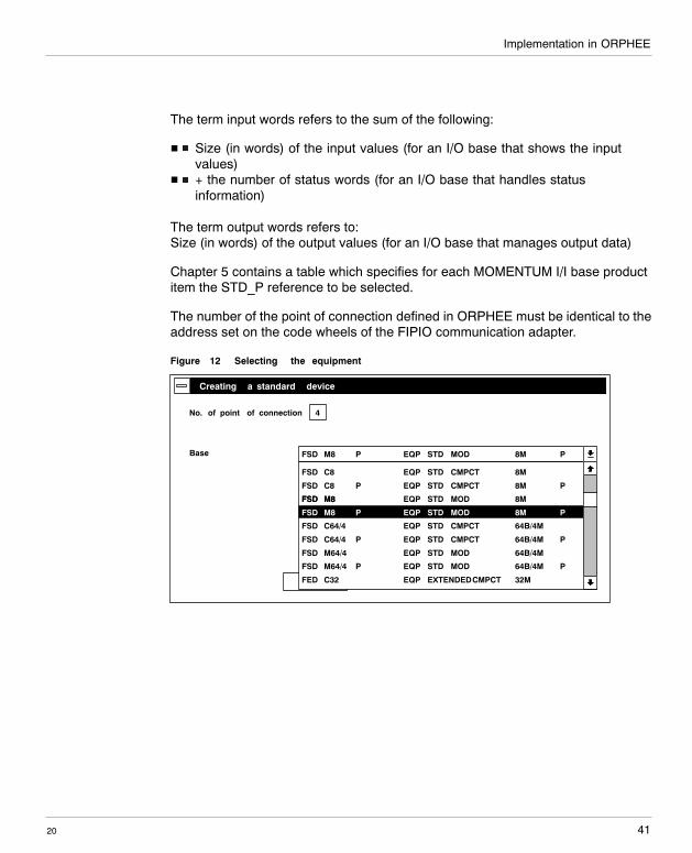
4.2 Equipment selection
The MOMENTUM device must be programmed within the STD_P configurationscreen family of the FIPIO bus. Access to the configuration screen of the FIPIObus requires prior declaration of a CPU5030 or CPU5130 (processors integratingthe FIPIO link).To connect a MOMENTUM device to FIPIO, click on the STD_P button, enter thenumber of the point of connection (1 to 62) and select the reference thatcorresponds to the I/O base used:
I/O base withoutparameters
I/O base with parameters
Number of input words <= 8 andnumber of output words < = 8
FSDM8 FSDM8P
Number of input words > 8 ornumber of output words > 8
FEDM32 FEDM32P
To determine the number of input and output words needed for the I/O base usedrefer to chapter 5 of this document or to the user manual of the I/O bases (870USE 002 00)
Implementation in ORPHEE
41
W idth: 178 mmHeight: 216 mm
20
The term input words refers to the sum of the following:
H Size (in words) of the input values (for an I/O base that shows the inputvalues)
H + the number of status words (for an I/O base that handles statusinformation)
The term output words refers to:Size (in words) of the output values (for an I/O base that manages output data)
Chapter 5 contains a table which specifies for each MOMENTUM I/I base productitem the STD_P reference to be selected.
The number of the point of connection defined in ORPHEE must be identical to theaddress set on the code wheels of the FIPIO communication adapter.
Figure 12 Selecting the equipment
Cancel
FSD M8
Creating a standard device
FSD M8
No. of point of connection 4
Base P EQP STD MOD 8M P
FSD C8 EQP STD CMPCT 8M
FSD C8 P EQP STD CMPCT 8M P
FSD M8 EQP STD MOD 8MFSD M8
P EQP STD MOD 8M P
EQP STD CMPCT 64B/4MFSD C64/4
P EQP STD CMPCT 64B/4M PFSD C64/4
EQP STD MOD 64B/4MFSD M64/4
P EQP STD MOD 64B/4M PFSD M64/4
EQP EXTENDEDCMPCT 32MFED C32
Implementation in ORPHEE
2042
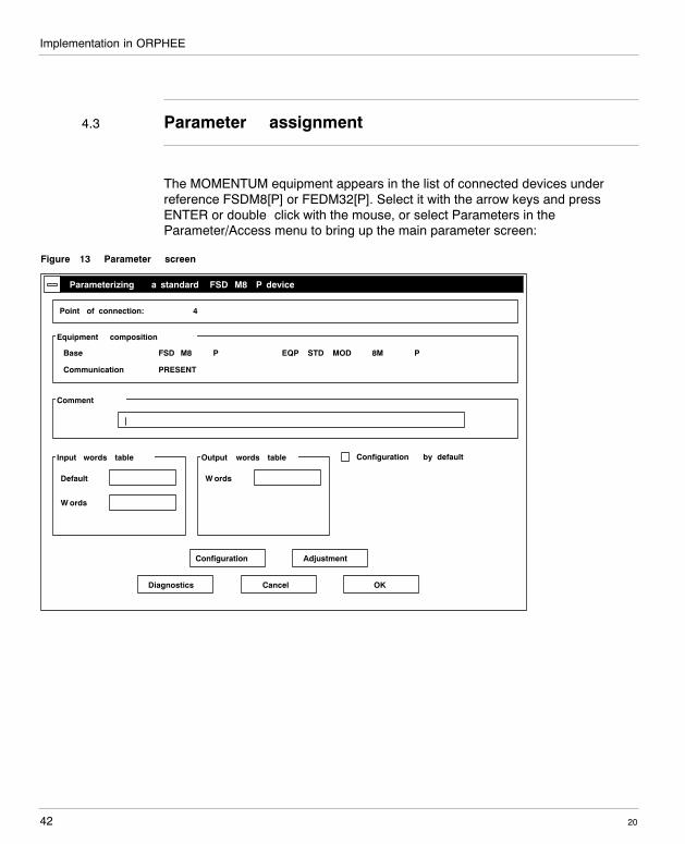
4.3 Parameter assignment
The MOMENTUM equipment appears in the list of connected devices underreference FSDM8[P] or FEDM32[P]. Select it with the arrow keys and pressENTER or double�click with the mouse, or select Parameters in theParameter/Access menu to bring up the main parameter screen:
Figure 13 Parameter screen
Cancel
Parameterizing a standard FSD M8 P device
Communication
Point of connection: 4
Diagnostics
Equipment composition
Base
Comment
|
PRESENT
FSD M8 P EQP STD MOD 8M P
Input words table
Default
W ords
Output words table
W ords
Configuration by default
OK
AdjustmentConfiguration
Implementation in ORPHEE
43
W idth: 178 mmHeight: 216 mm
20
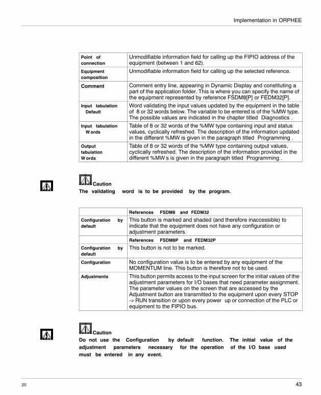
Point ofconnection
Unmodifiable information field for calling up the FIPIO address of theequipment (between 1 and 62).
Equipmentcomposition
Unmodifiable information field for calling up the selected reference.
Comment Comment entry line, appearing in Dynamic Display and constituting apart of the application folder. This is where you can specify the name ofthe equipment represented by reference FSDM8[P] or FEDM32[P].
Input tabulation� Default
Word validating the input values updated by the equipment in the tableof 8 or 32 words below. The variable to be entered is of the %MW type.The possible values are indicated in the chapter titled ”Diagnostics”.
Input tabulation� W ords
Table of 8 or 32 words of the %MW type containing input and statusvalues, cyclically refreshed. The description of the information updatedin the different %MW is given in the paragraph titled ”Programming”.
Outputtabulation �W ords
Table of 8 or 32 words of the %MW type containing output values,cyclically refreshed. The description of the information provided in thedifferent %MW’s is given in the paragraph titled ”Programming”.
CautionThe validating word is to be provided by the program.
References FSDM8 and FEDM32
Configuration bydefault
This button is marked and shaded (and therefore inaccessible) toindicate that the equipment does not have any configuration oradjustment parameters.References FSDM8P and FEDM32P
Configuration bydefault
This button is not to be marked.
Configuration No configuration value is to be entered by any equipment of theMOMENTUM line. This button is therefore not to be used.
Adjustments This button permits access to the input screen for the initial values of theadjustment parameters for I/O bases that need parameter assignment.The parameter values on the screen that are accessed by theAdjustment button are transmitted to the equipment upon every STOP-> RUN transition or upon every power�up or connection of the PLC orequipment to the FIPIO bus.
CautionDo not use the ”Configuration by default” function. The initial value of theadjustment parameters necessary for the operation of the I/O base usedmust be entered in any event.
Implementation in ORPHEE
2044
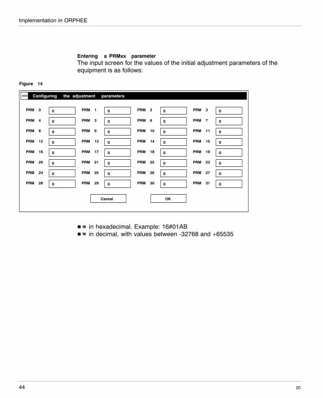
Entering a PRMxx parameterThe input screen for the values of the initial adjustment parameters of theequipment is as follows:
Figure 14
Cancel
Configuring the adjustment parameters
0PRM 0
OK
0PRM 4
0PRM 8
0PRM 12
0PRM 16
0PRM 20
0PRM 24
0PRM 28
0PRM 1
0PRM 3
0PRM 9
0PRM 13
0PRM 17
0PRM 21
0PRM 25
0PRM 29
0PRM 2
0PRM 6
0PRM 10
0PRM 14
0PRM 18
0PRM 22
0PRM 26
0PRM 30
0PRM 3
0PRM 7
0PRM 11
0PRM 15
0PRM 19
0PRM 23
0PRM 27
0PRM 31
H in hexadecimal. Example: 16#01ABH in decimal, with values between -32768 and +65535
Implementation in ORPHEE
45
W idth: 178 mmHeight: 216 mm
20
Refer to chapter 5 to determine the necessary number of parameter words as wellas for a description of the possible values and the order to be observed forentering the words (the first parameter word must be entered in PRM0).
CautionThe PRMxx words which are not used must absolutely be left at a value of 0.If not, the module won’t be parameterized (fault DL2).
CautionORPHEE does not check the parameter valuese entered; if an incorrect valueis used, it may prevent the equipment from being started up (in the case ofan inconsistent value) or from operating as intended (in the case of aconsistent value).
NoteThe adjustment values contained in the PRMx words can be modified with the aidof BFC WRIT_PRM (cf. paragraph ”Programming”). These initial values entered viaXTEL-CONF in the PRMx words are sent to the equipment each time it isinitialized.
Implementation in ORPHEE
2046
4.4 Programming
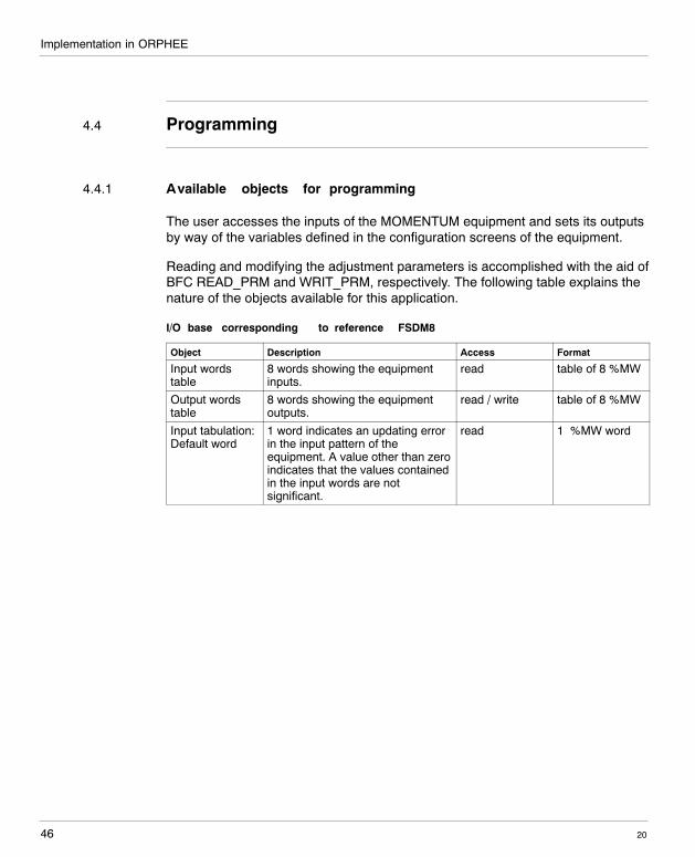
4.4.1 Available objects for programming
The user accesses the inputs of the MOMENTUM equipment and sets its outputsby way of the variables defined in the configuration screens of the equipment.
Reading and modifying the adjustment parameters is accomplished with the aid ofBFC READ_PRM and WRIT_PRM, respectively. The following table explains thenature of the objects available for this application.
I/O base corresponding to reference FSDM8
Object Description Access Format
Input wordstable
8 words showing the equipmentinputs.
read table of 8 %MW
Output wordstable
8 words showing the equipmentoutputs.
read / write table of 8 %MW
Input tabulation:Default word
1 word indicates an updating errorin the input pattern of theequipment. A value other than zeroindicates that the values containedin the input words are notsignificant.
read 1 %MW word
Implementation in ORPHEE
47
W idth: 178 mmHeight: 216 mm
20
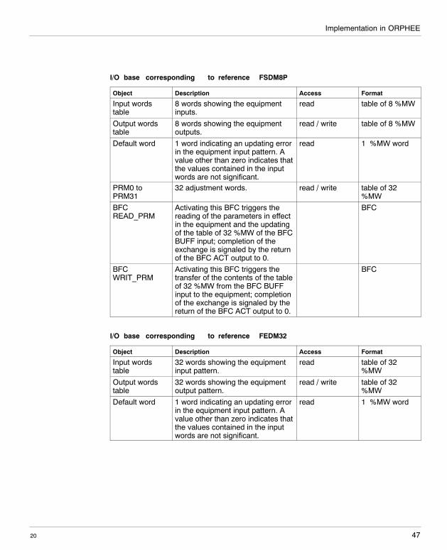
I/O base corresponding to reference FSDM8P
Object Description Access Format
Input wordstable
8 words showing the equipmentinputs.
read table of 8 %MW
Output wordstable
8 words showing the equipmentoutputs.
read / write table of 8 %MW
Default word 1 word indicating an updating errorin the equipment input pattern. Avalue other than zero indicates thatthe values contained in the inputwords are not significant.
read 1 %MW word
PRM0 toPRM31
32 adjustment words. read / write table of 32%MW
BFCREAD_PRM
Activating this BFC triggers thereading of the parameters in effectin the equipment and the updatingof the table of 32 %MW of the BFCBUFF input; completion of theexchange is signaled by the returnof the BFC ACT output to 0.
BFC
BFCWRIT_PRM
Activating this BFC triggers thetransfer of the contents of the tableof 32 %MW from the BFC BUFFinput to the equipment; completionof the exchange is signaled by thereturn of the BFC ACT output to 0.
BFC
I/O base corresponding to reference FEDM32
Object Description Access Format
Input wordstable
32 words showing the equipmentinput pattern.
read table of 32%MW
Output wordstable
32 words showing the equipmentoutput pattern.
read / write table of 32%MW
Default word 1 word indicating an updating errorin the equipment input pattern. Avalue other than zero indicates thatthe values contained in the inputwords are not significant.
read 1 %MW word
Implementation in ORPHEE
2048
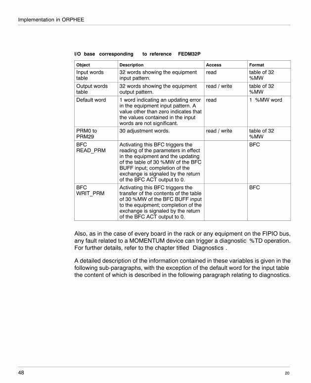
I/O base corresponding to reference FEDM32P
Object Description Access Format
Input wordstable
32 words showing the equipmentinput pattern.
read table of 32%MW
Output wordstable
32 words showing the equipmentoutput pattern.
read / write table of 32%MW
Default word 1 word indicating an updating errorin the equipment input pattern. Avalue other than zero indicates thatthe values contained in the inputwords are not significant.
read 1 %MW word
PRM0 toPRM29
30 adjustment words. read / write table of 32%MW
BFCREAD_PRM
Activating this BFC triggers thereading of the parameters in effectin the equipment and the updatingof the table of 30 %MW of the BFCBUFF input; completion of theexchange is signaled by the returnof the BFC ACT output to 0.
BFC
BFCWRIT_PRM
Activating this BFC triggers thetransfer of the contents of the tableof 30 %MW of the BFC BUFF inputto the equipment; completion of theexchange is signaled by the returnof the BFC ACT output to 0.
BFC
Also, as in the case of every board in the rack or any equipment on the FIPIO bus,any fault related to a MOMENTUM device can trigger a diagnostic %TD operation.For further details, refer to the chapter titled ”Diagnostics”.
A detailed description of the information contained in these variables is given in thefollowing sub-paragraphs, with the exception of the default word for the input tablethe content of which is described in the following paragraph relating to diagnostics.
Implementation in ORPHEE
49
W idth: 178 mmHeight: 216 mm
20
4.4.2 Equipment input pattern
Access to the inputs of the MOMENTUM equipment is obtained using the table of8/32 %MW words defined in the configuration editor.The PLC refreshes the table in cyclic fashion at the beginning of an automaticcontrol cycle prior to executing the application program.
The data distribution within the input words depends on the I/O base used, alongthe following principles:
H If the I/O base shows status information, that will appear following the inputvalues (up to now not realized).
H If the total amount of input information (status + input values) is less than 8or 32 words, the remaining words will be automatically forced to 0.
Symbolic names must be assigned to the input table. Each bit in the word can berepresented by a symbol if predefined by the declaration editor.
CautionThe content of these words is only to be considered significant if the defaultword of the input tabulations has a value of 0. In all other cases thetabulation words must not be used by the PLC program. Refer to the”Diagnostics” paragraph for a list of possible values of the input tabulationdefault word.
Chapter 5 contains a table which specifies for each MOMENTUM I/O base theorder and the significance of the input and output data.
Implementation in ORPHEE
2050
4.4.3 Equipment output pattern
Access to the outputs of the MOMENTUM equipment is obtained using the table of8/32 %MW words defined in the configuration editor.The PLC refreshes the entire table in cyclic fashion at the end of an automaticcontrol cycle after execution of the application program.
The data distribution within the output words depends on the I/O base used. If thetotal amount of output information is less than 8 or 32 words, the remaining wordsare not significant and are not transmitted to the base module by thecommunication adapter.
Symbolic names must be assigned to the input table. Each bit in the word can berepresented by a symbol if predefined by the declaration editor.
Chapter 5 contains a table which specifies for each MOMENTUM I/O base theorder and the significance of the input and output data.
Implementation in ORPHEE
51
W idth: 178 mmHeight: 216 mm
20
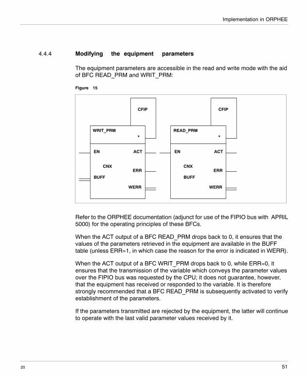
4.4.4 Modifying the equipment parameters
The equipment parameters are accessible in the read and write mode with the aidof BFC READ_PRM and WRIT_PRM:
Figure 15
WRIT_PRM
EN
CNX
BUFF
ACT
ERR
WERR
*
CFIP
READ_PRM
EN
CNX
BUFF
ACT
ERR
WERR
*
CFIP
Refer to the ORPHEE documentation (adjunct for use of the FIPIO bus with APRIL5000) for the operating principles of these BFCs.
When the ACT output of a BFC READ_PRM drops back to 0, it ensures that thevalues of the parameters retrieved in the equipment are available in the BUFFtable (unless ERR=1, in which case the reason for the error is indicated in WERR).
When the ACT output of a BFC WRIT_PRM drops back to 0, while ERR=0, itensures that the transmission of the variable which conveys the parameter valuesover the FIPIO bus was requested by the CPU; it does not guarantee, however,that the equipment has received or responded to the variable. It is thereforestrongly recommended that a BFC READ_PRM is subsequently activated to verifyestablishment of the parameters.
If the parameters transmitted are rejected by the equipment, the latter will continueto operate with the last valid parameter values received by it.
Implementation in ORPHEE
2052
4.5 Diagnostics
4.5.1 System diagnostics
The system diagnostic functions of the MOMENTUM equipment connected to theFIPIO bus are accessible on a dynamic display. It is possible:
H to read the hardware configuration and to compare it with the configurationprogrammed into the PLC,
H and to dynamically visualize the configuration in the configuration editor.
Refer to the ”adjunct for operating the FIPIO link with APRIL 5000” in the ORPHEEdocumentation (ref. TEM10000/10800F) for a review of the different operatingmodes.
For the MOMENTUM equipment, details of the device and possible faults can belooked up in the ”Diagnostic chart” function of the ”Diagnostics” menu throughdynamic visualization of the configuration editor.
Implementation in ORPHEE
53
W idth: 178 mmHeight: 216 mm
20
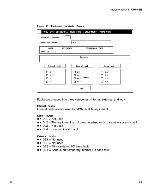
Figure 16 Equipment Analysis Screen
VISU DYN CONFIGURA TION FIPIO : EQUIPMENT ANAL YSIS
Point of connection: 2
RunOperating mode :
DI1
DI2
DI3
DI4
Internal fault
DE1
DE2
DE3
DE4
External fault
DL1
DL2
DL3
DL4
Logic fault
FSD C8
EXTENSION
OK
Comment
BASE COMMUNICA TION
P
Default
Faults are grouped into three categories : internal, external, and logic.
Internal faults:Internal faults are not used for MOMENTUM equipment.
Logic faults:H DL1 = Not usedH DL2 = The equipment is not parameterized or its parameters are not validH DL3 = Not usedH DL4 = Communication fault
External faults:H DE1 = Not usedH DE2 = Not usedH DE3 = Minor external I/O base faultH DE4 = Serious but temporary internal I/O base fault
Implementation in ORPHEE
2054
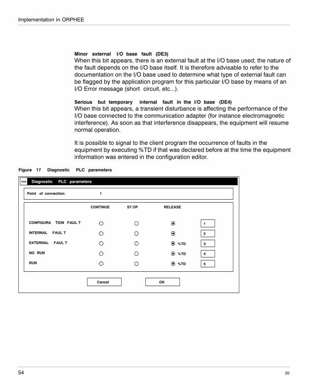
Minor external I/O base fault (DE3)When this bit appears, there is an external fault at the I/O base used; the nature ofthe fault depends on the I/O base itself. It is therefore advisable to refer to thedocumentation on the I/O base used to determine what type of external fault canbe flagged by the application program for this particular I/O base by means of anI/O Error message (short�circuit, etc...).
Serious but temporary internal fault in the I/O base (DE4)When this bit appears, a transient disturbance is affecting the performance of theI/O base connected to the communication adapter (for instance electromagneticinterference). As soon as that interference disappears, the equipment will resumenormal operation.
It is possible to signal to the client program the occurrence of faults in theequipment by executing %TD if that was declared before at the time the equipmentinformation was entered in the configuration editor.
Figure 17 Diagnostic PLC parameters
Cancel
Diagnostic PLC parameters
OK
1
2
3
4
Point of connection: 1
CONTINUE ST OP RELEASE
5
%TDCONFIGURA TION FAUL T
INTERNAL FAUL T
EXTERNAL FAUL T
NO RUN
RUN
%TD
%TD
%TD
%TD
Implementation in ORPHEE
55
W idth: 178 mmHeight: 216 mm
20
Triggering of an internal fault %TD:Not used
Triggering of a configuration fault %TD:A configuration fault is signalled in the following situations:
H Power supply failure in the I/O base moduleH The equipment cannot be connected to FIPIOH The device is missingH The equipment is not in operating condition and is off the network
Triggering of NO RUN %TD:Incorrect mode of operation of the equipment
Triggering of an external fault %TD:An external fault is signaled in the following situations:
H External type fault at the I/O baseH Transient internal fault in the I/O base
Triggering a RUN %TD:Any disappearance of a fault that occurred in the MOMENTUM equipment triggersthe execution of a RUN %TD.
As soon as a fault is indicated on the FIPIO bus, the indicators 9 and EXT FAULTof the CPU5030 or CPU5130 will light up.
4.5.2 Validating word for the equipment inputs
This 16-bit word called Fault, appearing on the parameter screen of an FSDM8[P]or FEDM32[P] reference device, indicates an error that occurred during theupdating of the pattern variables of the equipment inputs.
If that word equals 0, the input values of the equipment are valid and can be usedby the PLC program.
The high-order byte of this word is not significant.
The least significant byte of this word is processed by the FIPIO communicationadapter at the time of the input acquisition.
Implementation in ORPHEE
2056
The possible values of this byte are as follows:
H 0: The input values can be used by the programH FFh: The MOMENTUM equipment is not working; the input values cannot be
used by the programH 01: A minor external fault exists at the I/O base; the input values cannot be
used by the program (this corresponds to DE3)H 02: A serious temporary fault exists at the I/O base; the input values cannot
be used by the program (this corresponds to DE4)
When the MOMENTUM equipment is disconnected from the FIPIO bus or powereddown, the validating word takes on a value of FF (hexadecimal) and in this casethe words (input pattern) are no longer valid: They are held at their last valid value.
The default word, the words (input pattern) and the diagnostic information areupdated even when the PLC is in STOP mode.
4.5.3 Fault information occurring in input words
Depending on the type of I/O base used (for instance certain analog modules),certain fault information can be contained in the input pattern words relating to theequipment (out of range, broken wire).It will be advisable to refer to the I/O base documentation to determine whether theI/O base used shows status information or whether certain faults are indicated byvalues outside the range of the input values.
This information does not apply to the release of % TD nor to the indication offaults handled by the PLC (DE, DL).
4.5.4 Use of ORPHEE or ORPHEE DIAG for diagnostics
The dynamic display function of the ORPHEE configuration permits access to thedetailed diagnostic program of the MOMENTUM equipment and of any otherequipment connected to the FIPIO bus.

57
W idth: 178 mmHeight: 216 mm
20
Summary tables and parameterassignment 5
Summary tables and parameter assignment
2058
5.1 Programming MOMENTUM I/O bases with XTELand ORPHEE
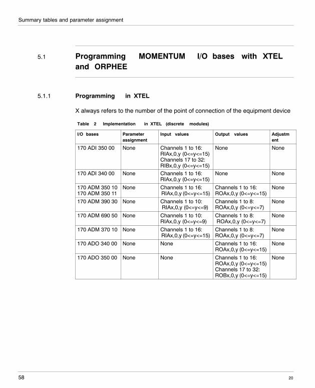
5.1.1 Programming in XTEL
X always refers to the number of the point of connection of the equipment device
Table 2 Implementation in XTEL (discrete modules)
I/O bases Parameterassignment
Input values Output values Adjustment
170 ADI 350 00 None Channels 1 to 16:RIAx,0,y (0<=y<=15)Channels 17 to 32:RIBx,0,y (0<=y<=15)
None None
170 ADI 340 00 None Channels 1 to 16:RIAx,0,y (0<=y<=15)
None None
170 ADM 350 10170 ADM 350 11
None Channels 1 to 16:RIAx,0,y (0<=y<=15)
Channels 1 to 16:ROAx,0,y (0<=y<=15)
None
170 ADM 390 30 None Channels 1 to 10:RIAx,0,y (0<=y<=9)
Channels 1 to 8:ROAx,0,y (0<=y<=7)
None
170 ADM 690 50 None Channels 1 to 10:RIAx,0,y (0<=y<=9)
Channels 1 to 8:ROAx,0,y (0<=y<=7)
None
170 ADM 370 10 None Channels 1 to 16:RIAx,0,y (0<=y<=15)
Channels 1 to 8:ROAx,0,y (0<=y<=7)
None
170 ADO 340 00 None None Channels 1 to 16:ROAx,0,y (0<=y<=15)
None
170 ADO 350 00 None None Channels 1 to 16:ROAx,0,y (0<=y<=15)Channels 17 to 32:ROBx,0,y (0<=y<=15)
None
Summary tables and parameter assignment
59
W idth: 178 mmHeight: 216 mm
20
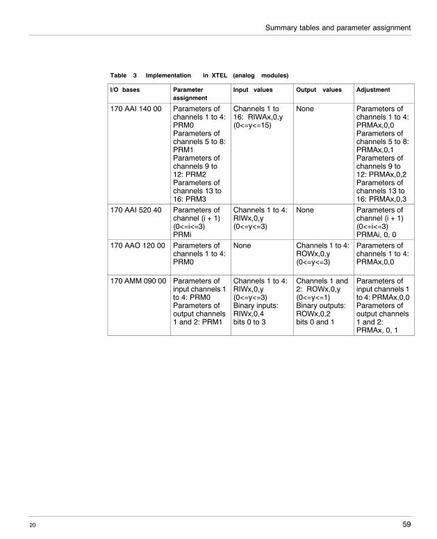
Table 3 Implementation in XTEL (analog modules)
I/O bases Parameterassignment
Input values Output values Adjustment
170 AAI 140 00 Parameters ofchannels 1 to 4:PRM0Parameters ofchannels 5 to 8:PRM1Parameters ofchannels 9 to12: PRM2Parameters ofchannels 13 to16: PRM3
Channels 1 to16: RIWAx,0,y(0<=y<=15)
None Parameters ofchannels 1 to 4:PRMAx,0,0Parameters ofchannels 5 to 8:PRMAx,0,1Parameters ofchannels 9 to12: PRMAx,0,2Parameters ofchannels 13 to16: PRMAx,0,3
170 AAI 520 40 Parameters ofchannel (i + 1)(0<=i<=3)PRMi
Channels 1 to 4:RIWx,0,y(0<=y<=3)
None Parameters ofchannel (i + 1)(0<=i<=3)PRMAi, 0, 0
170 AAO 120 00 Parameters ofchannels 1 to 4:PRM0
None Channels 1 to 4:ROWx,0,y(0<=y<=3)
Parameters ofchannels 1 to 4:PRMAx,0,0
170 AMM 090 00 Parameters ofinput channels 1to 4: PRM0Parameters ofoutput channels1 and 2: PRM1
Channels 1 to 4:RIWx,0,y(0<=y<=3)Binary inputs:RIWx,0,4bits 0 to 3
Channels 1 and2: ROWx,0,y(0<=y<=1)Binary outputs:ROWx,0,2bits 0 and 1
Parameters ofinput channels 1to 4: PRMAx,0,0Parameters ofoutput channels1 and 2:PRMAx, 0, 1
Summary tables and parameter assignment
2060
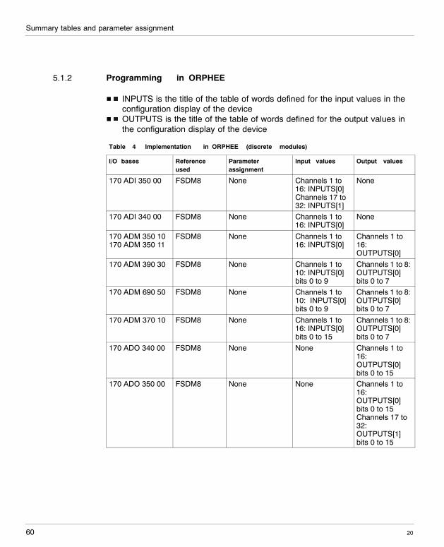
5.1.2 Programming in ORPHEE
H INPUTS is the title of the table of words defined for the input values in theconfiguration display of the device
H OUTPUTS is the title of the table of words defined for the output values inthe configuration display of the device
Table 4 Implementation in ORPHEE (discrete modules)
I/O bases Referenceused
Parameterassignment
Input values Output values
170 ADI 350 00 FSDM8 None Channels 1 to16: INPUTS[0]Channels 17 to32: INPUTS[1]
None
170 ADI 340 00 FSDM8 None Channels 1 to16: INPUTS[0]
None
170 ADM 350 10170 ADM 350 11
FSDM8 None Channels 1 to16: INPUTS[0]
Channels 1 to16:OUTPUTS[0]
170 ADM 390 30 FSDM8 None Channels 1 to10: INPUTS[0]bits 0 to 9
Channels 1 to 8:OUTPUTS[0]bits 0 to 7
170 ADM 690 50 FSDM8 None Channels 1 to10: INPUTS[0]bits 0 to 9
Channels 1 to 8:OUTPUTS[0]bits 0 to 7
170 ADM 370 10 FSDM8 None Channels 1 to16: INPUTS[0]bits 0 to 15
Channels 1 to 8:OUTPUTS[0]bits 0 to 7
170 ADO 340 00 FSDM8 None None Channels 1 to16:OUTPUTS[0]bits 0 to 15
170 ADO 350 00 FSDM8 None None Channels 1 to16:OUTPUTS[0]bits 0 to 15Channels 17 to32:OUTPUTS[1]bits 0 to 15
Summary tables and parameter assignment
61
W idth: 178 mmHeight: 216 mm
20
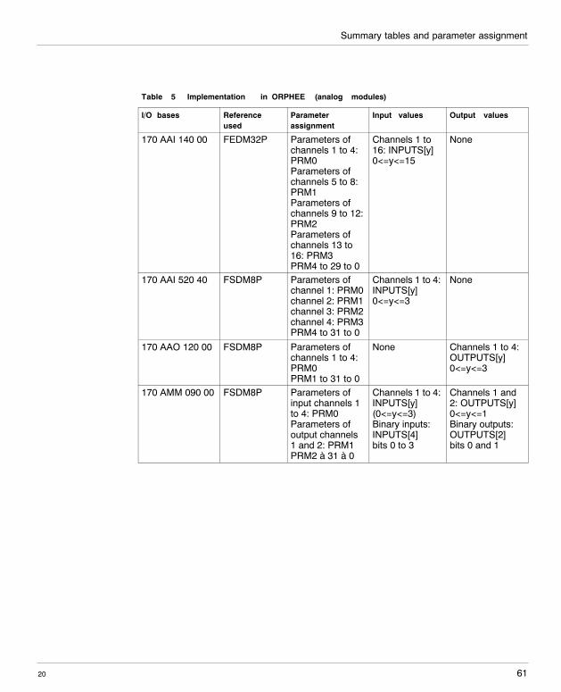
Table 5 Implementation in ORPHEE (analog modules)
I/O bases Referenceused
Parameterassignment
Input values Output values
170 AAI 140 00 FEDM32P Parameters ofchannels 1 to 4:PRM0Parameters ofchannels 5 to 8:PRM1Parameters ofchannels 9 to 12:PRM2Parameters ofchannels 13 to16: PRM3PRM4 to 29 to 0
Channels 1 to16: INPUTS[y]0<=y<=15
None
170 AAI 520 40 FSDM8P Parameters ofchannel 1: PRM0channel 2: PRM1channel 3: PRM2channel 4: PRM3PRM4 to 31 to 0
Channels 1 to 4:INPUTS[y]0<=y<=3
None
170 AAO 120 00 FSDM8P Parameters ofchannels 1 to 4:PRM0PRM1 to 31 to 0
None Channels 1 to 4:OUTPUTS[y]0<=y<=3
170 AMM 090 00 FSDM8P Parameters ofinput channels 1to 4: PRM0Parameters ofoutput channels1 and 2: PRM1PRM2 à 31 à 0
Channels 1 to 4:INPUTS[y](0<=y<=3)Binary inputs:INPUTS[4]bits 0 to 3
Channels 1 and2: OUTPUTS[y]0<=y<=1Binary outputs:OUTPUTS[2]bits 0 and 1
Summary tables and parameter assignment
2062
5.2 Parameterizing analog modules
In this section the possible parameters will be presented in keyword form for all I/Obases.
Detailed explanations, for example range evaluation, can be found in thecorresponding module descriptions in the 870 USE 002 00 manual.
Summary tables and parameter assignment
63
W idth: 178 mmHeight: 216 mm
20
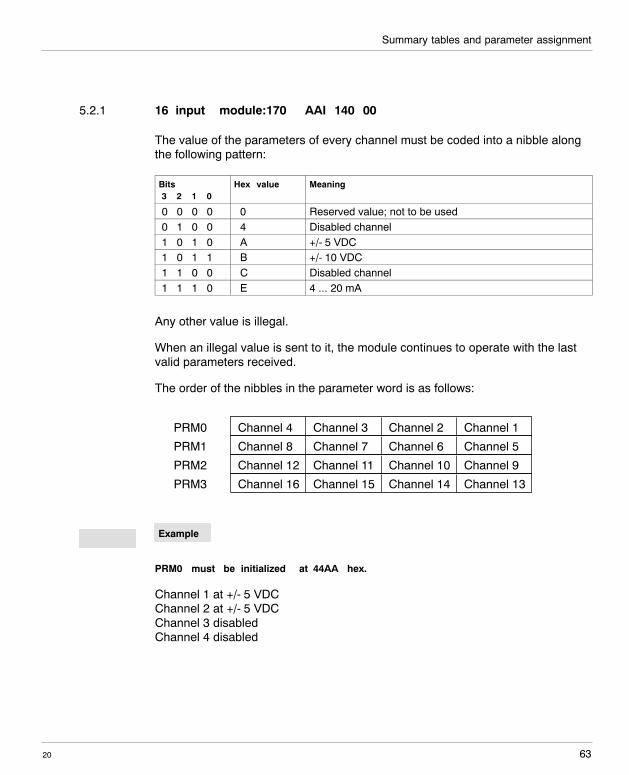
5.2.1 16�input module:170 AAI 140 00
The value of the parameters of every channel must be coded into a nibble alongthe following pattern:
Bits3 2 1 0
Hex value Meaning
0 0 0 0 0 Reserved value; not to be used0 1 0 0 4 Disabled channel1 0 1 0 A +/- 5 VDC1 0 1 1 B +/- 10 VDC1 1 0 0 C Disabled channel1 1 1 0 E 4 ... 20 mA
Any other value is illegal.
When an illegal value is sent to it, the module continues to operate with the lastvalid parameters received.
The order of the nibbles in the parameter word is as follows:
PRM0 Channel 4 Channel 3 Channel 2 Channel 1
PRM1 Channel 8 Channel 7 Channel 6 Channel 5
PRM2 Channel 12 Channel 11 Channel 10 Channel 9
PRM3 Channel 16 Channel 15 Channel 14 Channel 13
Example
PRM0 must be initialized at 44AA hex.
Channel 1 at +/- 5 VDCChannel 2 at +/- 5 VDCChannel 3 disabledChannel 4 disabled
Example
Summary tables and parameter assignment
2064
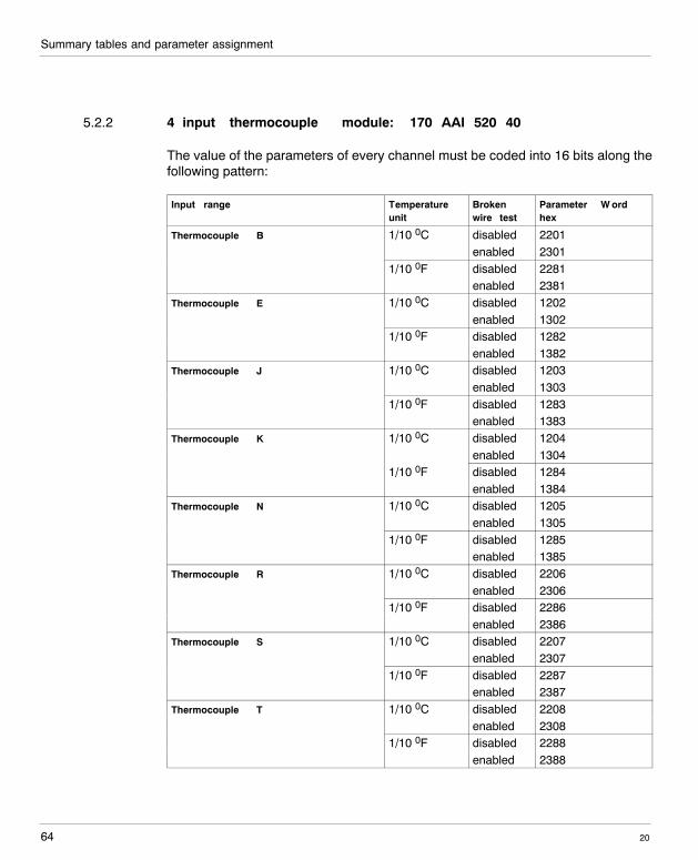
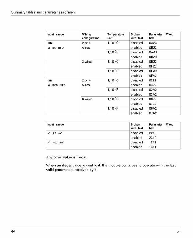
5.2.2 4�input thermocouple module: 170 AAI 520 40
The value of the parameters of every channel must be coded into 16 bits along thefollowing pattern:
Input range Temperatureunit
Brokenwire test
Parameter W ordhex
Thermocouple B 1/10 0C disabled 2201enabled 2301
1/10 0F disabled 2281enabled 2381
Thermocouple E 1/10 0C disabled 1202enabled 1302
1/10 0F disabled 1282enabled 1382
Thermocouple J 1/10 0C disabled 1203enabled 1303
1/10 0F disabled 1283enabled 1383
Thermocouple K 1/10 0C disabled 1204enabled 1304
1/10 0F disabled 1284enabled 1384
Thermocouple N 1/10 0C disabled 1205enabled 1305
1/10 0F disabled 1285enabled 1385
Thermocouple R 1/10 0C disabled 2206enabled 2306
1/10 0F disabled 2286enabled 2386
Thermocouple S 1/10 0C disabled 2207enabled 2307
1/10 0F disabled 2287enabled 2387
Thermocouple T 1/10 0C disabled 2208enabled 2308
1/10 0F disabled 2288enabled 2388
Summary tables and parameter assignment
65
W idth: 178 mmHeight: 216 mm
20
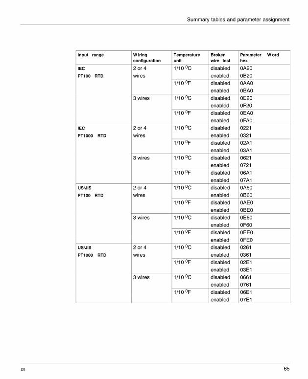
Input range W iringconfiguration
Temperatureunit
Brokenwire test
Parameter W ordhex
IEC 2 or 4 1/10 0C disabled 0A20PT100 RTD wires enabled 0B20
1/10 0F disabled 0AA0enabled 0BA0
3 wires 1/10 0C disabled 0E20enabled 0F20
1/10 0F disabled 0EA0enabled 0FA0
IEC 2 or 4 1/10 0C disabled 0221PT1000 RTD wires enabled 0321
1/10 0F disabled 02A1enabled 03A1
3 wires 1/10 0C disabled 0621enabled 0721
1/10 0F disabled 06A1enabled 07A1
US/JIS 2 or 4 1/10 0C disabled 0A60PT100 RTD wires enabled 0B60
1/10 0F disabled 0AE0enabled 0BE0
3 wires 1/10 0C disabled 0E60enabled 0F60
1/10 0F disabled 0EE0enabled 0FE0
US/JIS 2 or 4 1/10 0C disabled 0261PT1000 RTD wires enabled 0361
1/10 0F disabled 02E1enabled 03E1
3 wires 1/10 0C disabled 0661enabled 0761
1/10 0F disabled 06E1enabled 07E1
Summary tables and parameter assignment
2066
Input range W iringconfiguration
Temperatureunit
Brokenwire test
Parameter W ordhex
DIN 2 or 4 1/10 0C disabled 0A23Ni 100 RTD wires enabled 0B23
1/10 0F disabled 0AA3enabled 0BA3
3 wires 1/10 0C disabled 0E23enabled 0F23
1/10 0F disabled 0EA3enabled 0FA3
DIN 2 or 4 1/10 0C disabled 0222Ni 1000 RTD wires enabled 0322
1/10 0F disabled 02A2enabled 03A2
3 wires 1/10 0C disabled 0622enabled 0722
1/10 0F disabled 06A2enabled 07A2
Input range Brokenwire test
Parameter W ordhex
+/� 25 mV disabled 2210enabled 2310
+/� 100 mV disabled 1211enabled 1311
Any other value is illegal.
When an illegal value is sent to it, the module continues to operate with the lastvalid parameters received by it.
Summary tables and parameter assignment
67
W idth: 178 mmHeight: 216 mm
20
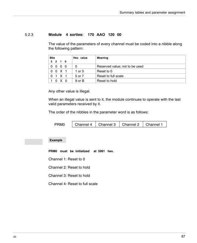
5.2.3 Module 4 sorties: 170 AAO 120 00
The value of the parameters of every channel must be coded into a nibble alongthe following pattern:
Bits3 2 1 0
Hex value Meaning
0 0 0 0 0 Reserved value; not to be used0 0 X 1 1 or 3 Reset to 00 1 X 1 5 or 7 Reset to full scale1 0 X 0 9 or B Reset to hold
Any other value is illegal.
When an illegal value is sent to it, the module continues to operate with the lastvalid parameters received by it.
The order of the nibbles in the parameter word is as follows:
PRM0 Channel 4 Channel 3 Channel 2 Channel 1
Example
PRM0 must be initialized at 5991 hex.
Channel 1: Reset to 0
Channel 2: Reset to hold
Channel 3: Reset to hold
Channel 4: Reset to full scale
Example
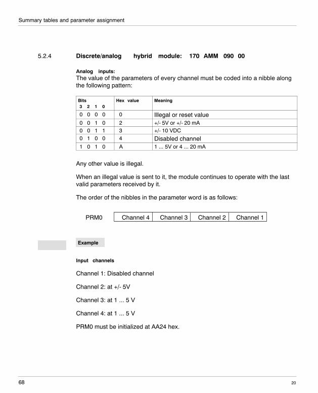
Summary tables and parameter assignment
2068
5.2.4 Discrete/analog hybrid module: 170 AMM 090 00
Analog inputs:The value of the parameters of every channel must be coded into a nibble alongthe following pattern:
Bits3 2 1 0
Hex value Meaning
0 0 0 0 0 Illegal or reset value0 0 1 0 2 +/- 5V or +/- 20 mA0 0 1 1 3 +/- 10 VDC0 1 0 0 4 Disabled channel1 0 1 0 A 1 ... 5V or 4 ... 20 mA
Any other value is illegal.
When an illegal value is sent to it, the module continues to operate with the lastvalid parameters received by it.
The order of the nibbles in the parameter word is as follows:
PRM0 Channel 4 Channel 3 Channel 2 Channel 1
Example
Input channels
Channel 1: Disabled channel
Channel 2: at +/- 5V
Channel 3: at 1 ... 5 V
Channel 4: at 1 ... 5 V
PRM0 must be initialized at AA24 hex.
Example
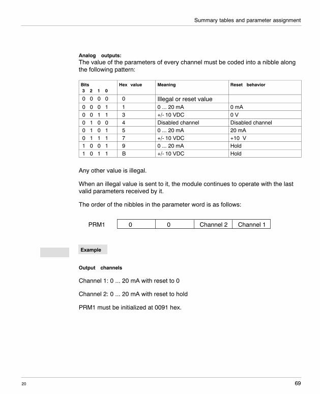
Summary tables and parameter assignment
69
W idth: 178 mmHeight: 216 mm
20
Analog outputs:The value of the parameters of every channel must be coded into a nibble alongthe following pattern:
Bits3 2 1 0
Hex value Meaning Reset behavior
0 0 0 0 0 Illegal or reset value0 0 0 1 1 0 ... 20 mA 0 mA0 0 1 1 3 +/- 10 VDC 0 V0 1 0 0 4 Disabled channel Disabled channel0 1 0 1 5 0 ... 20 mA 20 mA0 1 1 1 7 +/- 10 VDC +10 V1 0 0 1 9 0 ... 20 mA Hold1 0 1 1 B +/- 10 VDC Hold
Any other value is illegal.
When an illegal value is sent to it, the module continues to operate with the lastvalid parameters received by it.
The order of the nibbles in the parameter word is as follows:
PRM1 0 0 Channel 2 Channel 1
Example
Output channels
Channel 1: 0 ... 20 mA with reset to 0
Channel 2: 0 ... 20 mA with reset to hold
PRM1 must be initialized at 0091 hex.
Example

Summary tables and parameter assignment
2070
Recommended