INTERPRAEVENT 2016 – Conference Proceedings | 203
DATA ACQUISITION AND MODELLING (MONITORING, PROCESSES, TECHNOLOGIES, MODELS)
IP_2016_FP026
1 WSL Institute for Snow and Avalanche Research SLF, Davos Dorf, SWITZERLAND, [email protected]
2 Swiss Federal Institute for Forest, Landscape and Snow Research WSL
3 WSL Institute for Snow and Avalanche Research SLF
Modeling rockfall trajectories with non-smooth contact/impact mechanicsPerry Bartelt1; Werner Gerber2; Marc Christen2; Yves Bühler1
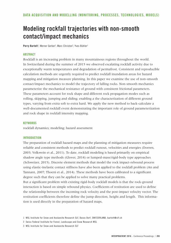
ABSTRACTRockfall is an increasing problem in many mountainous regions throughout the world.
In Switzerland during the summer of 2015 we observed escalating rockfall activity due to
exceptionally warm temperatures and degradation of permafrost. Consistent and reproducible
calculation methods are urgently required to predict rockfall inundation areas for hazard
mapping and mitigation measure planning. In this paper we examine the use of non-smooth
contact/impact mechanics to model the trajectory of falling rocks. Non-smooth mechanics
parameterize the mechanical resistance of ground with consistent frictional parameters.
These parameters account for rock shape and different rock propagation modes such as
rolling, skipping, jumping and sliding; enabling a the characterization of different ground
types, varying from extra soft to extra hard. We apply the new method to back-calculate a
well-documented rockfall event demonstrating the important role of ground parameterization
and rock shape in rockfall intensity mapping.
KEYWORDSrockfall dynamics; modeling; hazard assessment
INTRODUCTIONThe preparation of rockfall hazard maps and the planning of mitigation measures require
reliable and consistent methods to predict rockfall runout, velocities and energies (Dorren,
2003; Volkwein et al., 2011). To date, rockfall modeling is based primarily on empirical
shadow angle type methods (Glover, 2014) or lumped-mass/rigid-body type approaches
(Schweizer, 2015). Discrete element methods that model the rock impact-rebound process
using elastic-inelastic contact stiffness have also been applied to the rockfall problem (An and
Tannant, 2007; Thoeni et al., 2014). These methods have been calibrated to a significant
degree such that they can be applied to solve many practical problems.
But a significant problem with existing rigid-body rockfall models is that the rock-ground
interaction is based on simple rebound physics. Coefficients of restitution are used to define
the relationship between the incoming rock velocity and the post-impact velocity vector. The
restitution coefficients therefore define the jump direction, height and length. This informa-
tion is used directly in the preparation of hazard maps.
204 | INTERPRAEVENT 2016 – Conference Proceedings
The implicit assumption of rebound physics, however, is that rocks jump, a-priori. The entire
rock-ground interaction is condensed to a single time point. Rocks do not slide or roll and
remain in contact with the ground. Some rigid-body models account for rock rotations in the
in-flight phase, but the influence of rock rotations during impact is generally ignored as the
restitution coefficients are defined with respect to the translational velocity. The restitution
coefficients are independent of the impact configuration, which depends on the rock shape
and rock orientation at the time of impact (Glover, 2015).
To overcome this problem, many rockfall models use stochastic methods to describe the
rock-ground interaction. Random number generators that account for the variability of the
impact process essentially produce restitution coefficients. It is argued that the ground is
variable and therefore the restitution coefficients must likewise vary. The variability of the
impact configuration (rock size, shape, orientation, rotation) is not considered. Because rocks
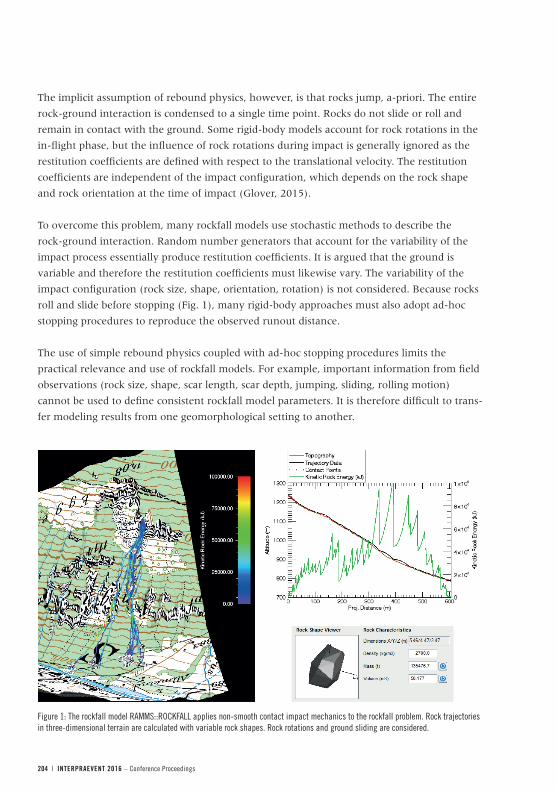
roll and slide before stopping (Fig. 1), many rigid-body approaches must also adopt ad-hoc
stopping procedures to reproduce the observed runout distance.
The use of simple rebound physics coupled with ad-hoc stopping procedures limits the
practical relevance and use of rockfall models. For example, important information from field
observations (rock size, shape, scar length, scar depth, jumping, sliding, rolling motion)
cannot be used to define consistent rockfall model parameters. It is therefore difficult to trans-
fer modeling results from one geomorphological setting to another.
Figure 1: The rockfall model RAMMS::ROCKFALL applies non-smooth contact impact mechanics to the rockfall problem. Rock trajectories in three-dimensional terrain are calculated with variable rock shapes. Rock rotations and ground sliding are considered.
INTERPRAEVENT 2016 – Conference Proceedings | 205
METHODS: NON-SMOOTH CONTACT/IMPACT MECHANICSTo overcome this problem, newly developed methods to treat the contact and impact were
applied to the rockfall problem (Schweizer, 2015). The methods were introduced in the
natural hazard program RAMMS (Christen et al. 2012) and applied to model observed
rockfall events. The components of the model are:
– Rock shape, size and impact configuration. Rocks are described by point clouds that
represent the complex surface topology (Fig. 2). Rocks can therefore have different forms,
varying from equant to plate like. Rock size can vary from 0.5 m3 (rockfall) up to 100 m3
(blockfall). Impact forces are applied on the rock surface, depending on the impact
configuration, leading to rock rotations and a natural modeling of lateral dispersion.
– Rock rotations, quaternions and gyroscopic forces. Rock rotations are considered not
only in the in-flight phase, but also during the contact/impact phase. Thus, rolling and
sliding can be modeled. Computationally efficient quaternion algebra is used to define the
orientation of the rock. Gyroscopic forces resulting from the rock rotations will upright
plate-like rock shapes producing dangerous wheel-type trajectories.
– Set-valued contact laws with friction. Set-valued force laws are used to describe
stick-slip type phenomena (Fig. 2). They allow sliding with friction. These laws are essential
to initiate rock-jumping and therefore long rock runout. Set-valued force laws are
non-stochastic and therefore can be transferred to similar terrain. Restitution coefficients
are not used to parameterize the rock-ground interaction, rather the sliding friction
parameters. Soft ground allows more sliding and therefore true rock stopping without
ad-hoc conditions.
PARAMETERIZATION OF GROUND FRICTIONThe most significant difference between rebound models and non-smooth contact/impact
models is the parameterization of ground friction. Rebound models simulate ground hardness
with apparent restitution coefficients that describe the bounciness of the terrain for a single
impact and point. In non-smooth models, ground impact is considered over a finite sliding
distance s , which we term the scarring length (Fig. 2). The scarring length s is defined when
any point on the surface of the rock is in contact with the ground. Contact is not defined with
respect to the rock’s center-of-mass, rather with respect to the complex surface geometry of
the rock. Contact forces, including friction, are therefore introduced at the surface of the rock
and cause rock rotations. The magnitude of the rotation at exit (when the rock departs the
scar) are therefore dependent on the orientation of the when it hits the ground. A restitution
coefficient ε is applied at the rock surface to account for energy dissipation in the normal
direction. The model uses ε = 0 (fully plastic) for all terrain types. Bounce heights are purely
a function of the impact orientation and the friction in the tangential direction. Hard ground
does not allow sliding and therefore produces bouncing modes of propagation. The ground
scar is being created at the speed and given by
206 | INTERPRAEVENT 2016 – Conference Proceedings
Equation 1
where is the sliding speed of the rock and β is a parameter controlling ramping effects,
created when ground material is being displaced during the scar formation. When the ground
is soft β is small because the ground is softer and the rock remains in contact with the ground
longer (Fig. 2). The scar parameter β serves to extend the time that ground friction, or any
other drag process, operates on the rock. It is therefore a useful parameter to describe
low-lying vegetation layers in forests.
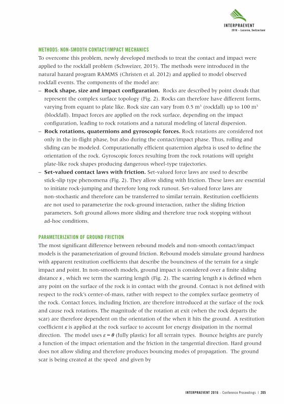
When the rock is in contact with the ground friction is described by a combination of
Coulomb friction SN and viscous friction SV. These forces act in the tangential direction; that is,
in the direction opposite to the rock velocity. The Coulomb friction coefficient μ(s) for s > 0 is
given by the transcendental function
Equation 2
This function contains three parameters: μmin , μmax and κ , see Fig. 2. The parameter μmin
defines the initial friction at the beginning of the ground interaction. Softer ground has lower
μmin values. We then assume that during the ground interaction that the rock penetrates the
ground and because of confining pressures ground material cannot be easily displaced out of
the scar. This leads to an increase of friction, or scar hardening. The maximum friction is
defined by μmax which we regard as a limit friction value, constant for all soils, but very low for
easily deformable and porous ground materials like snow. An important parameter is κ which
defines how a quickly the ground material changes from μmin to μmax which is a function of
how easily a ground material compresses (in the sliding direction) during ground penetration.
Figure 2: a) The interaction of the rock with the ground interface involves prolonged frictional sliding. This complex process is not governed by apparent restitution coefficients, rather mechanical properties of the ground under large deformation and strain-rates. Impulsive rebound forces coupled with frictional torques induce rock rotations leading to skipping/spinning-type propagation modes. b) Coulomb friction is parameterized as a function of the sliding distance using four parameters: μmin , μmax , κ and β. An additional velocity dependent drag ν accounts for viscous strain-rate effects during ground penetration/deformation.
( ) )arctan(2
)( minmaxmin ss κµµπ
µµ −+= .
contact no ifcontact if
⎩⎨⎧
−=
sv
sβ
⎨⎧ v
INTERPRAEVENT 2016 – Conference Proceedings | 207
These parameters may well be seasonally dependent, for example, a function of whether the
ground is frozen or unfrozen, or a function of the water content.
The Coulomb friction term is supplemented with a viscous, rate-dependent friction
Equation 3where M is the total mass of the rock and ν is the viscous drag coefficient. The softer the
ground, the larger is the viscous coefficient.With this five parameter frictional model it is
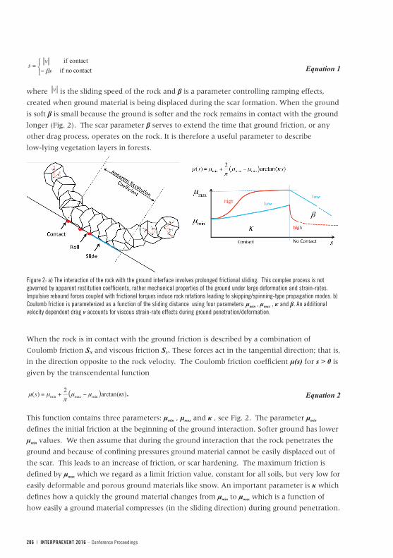
possible to establish seven general ground categories: Extra Soft, Soft, Medium Soft,
Medium, Medium Hard, Hard and Extra Hard, see Table 1. These categories differ in the
degree of a) sliding friction, b) bounciness, c) ground contact time and d) viscous drag.
Depending on the rock-ground impact configuration, different propagation modes can result,
varying from extreme braking in soft terrain (Extra Soft) to extreme jumps on hard ground
(Extra Hard). An eighth category, Snow, was especially introduced to account for extremely
low friction sliding modes.
The parameter values were determined using a combination of labortory tests, experimental
investigations in the field and application on documented case studies (Glover, 2014).
Clearly, more work will be performed in this direction in the near future.
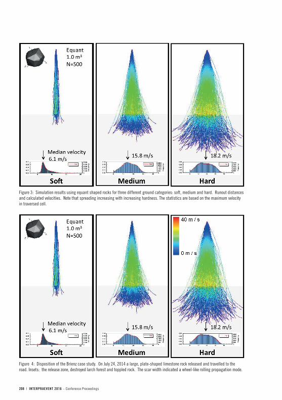
As shown in Fig. 3, the different ground categories result not only in different runout
distances, but also propagation velocities and spreading behavior. In this example an ideal 30°
slope was used to compare the different hardness categories. An equant shaped rock was used
and started with different orientations. The large spread in trajectories, especially in hard
terrain, is therefore obtained by changing the initial conditions and not by random rebound
coefficients during the process modeling.
Table 1: Ground categories and associated friction parameters in the RAMMS::ROCKFALL program
Category Picture Description Parameters Category Picture Description Parameters
Extra Soft Moor
Very wet ground. Cannot cross without deep sink-in.
µmin: 0.2 µmax: 2 β: 50 κ: 1 ν: 0.9
Medium Hard Shallow Meadow
Rocks jump. Penetration depths are small. Ground is flat. Rocky debris is present. Non-paved mountain roads.
µmin: 0.4 µmax: 2 β: 175 κ: 2.5 v: 0.5
Soft Moist, deep Meadow
Soft ground with many deep soil layers. Ground contains no large rock fragments. Often very moist. Foot indundations remain and are visible.
µmin: 0.25 µmax: 2 β: 100 κ: 1.25 ν: 0.8
Hard Rock scree
Rocks jump over ground. Mixture of large and small rocks. Usually without vegetation.
µmin: 0.55 µmax: 2 β: 185 κ: 3 v: 0.4
Medium Soft Deep Meadow
Rocks penetrate meadow surface leaving impact scars. Soil is deep, few rock fragments.
µmin: 0.3 µmax: 2 β: 125 κ: 1.5 ν: 0.7
Extra Hard Rockface / Bedrock
Ground is very hard and is marginally deformed by rocks. Rockface and paved roads.
µmin: 0.8 µmax: 2 β: 200 κ: 4 v: 0.3
Medium Meadow
Meadow is deep, but contains rock fragments. The meadow can be covered with vegetation.
µmin: 0.35 µmax: 2 β: 150 κ: 2 v: 0.6
Snow Rocks slide on snow surface.
µmin: 0.1 µmax: 0.35 β: 150 κ: 2 v: 0.7
/
/
/
/ /
/ /
/
compresses (in the sliding direction) during ground penetration. These parameters may well be 96
seasonally dependent, for example, a function of whether the ground is fro en or unfro en, or a 97
function of the water content. 98
The Coulomb friction term is supplemented with a viscous, rate-dependent friction, 99
vMSV ν−= Equation 3 100
where M is the total mass of the rock and ν is the viscous drag coefficient. The softer the ground, 101
the larger is the viscous coefficient. 102
TAB E 1 103
With this five parameter frictional model it is possible to establish seven general ground 104
categories: Extra Soft, Soft, edium Soft, edium, edium Hard, Hard and Extra Hard, see Table 105
1. These categories differ in the degree of a) sliding friction, b) bounciness, c) ground contact time 106
and d) viscous drag. epending on the rock-ground impact configuration, different propagation 107
modes can result, varying from extreme braking in soft terrain (Extra Soft) to extreme umps on 108
hard ground (Extra Hard). An eighth category, Snow, was especially introduced to account for 109
extremely low friction sliding modes. 110
The parameter values were determined using a combination of labortory tests, experimental 111
investigations in the field and application on documented case studies (Glover, 2014). Clearly, 112
more work will be performed in this direction in the near future. 113
FIGURE 3 114 115 As shown in Fig. 3, the different ground categories result not only in different runout distances, but 116
also propagation velocities and spreading behavior. In this example an ideal 30o slope was used to 117
compare the different hardness categories. An equant shaped rock was used and started with 118
different orientations. The large spread in tra ectories, especially in hard terrain, is therefore 119
obtained by changing the initial conditions and not by random rebound coefficients during the 120
process modeling. 121
Results: The Brien (GR) case study 122
The village of Brien , Canton Grisons (GR), Swit erland is the site of much on-going rockfall activity. 123
n uly 24, 2014 a 94 ton, 34 m3 plate-like rock detached from the upper limestone layer (1650 m 124
208 | INTERPRAEVENT 2016 – Conference Proceedings
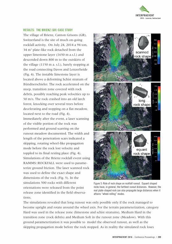
Figure 4: Disposition of the Brienz case study. On July 24, 2014 a large, plate-shaped limestone rock released and travelled to the road. Insets: the release zone, destroyed larch forest and toppled rock. The scar width indicated a wheel-like rolling propagation mode.
Figure 3: Simulation results using equant shaped rocks for three different ground categories: soft, medium and hard. Runout distances and calculated velocities. Note that spreading increasing with increasing hardness. The statistics are based on the maximum velocity in traversed cell.
INTERPRAEVENT 2016 – Conference Proceedings | 209
RESULTS: THE BRIENZ (GR) CASE STUDYThe village of Brienz, Canton Grisons (GR),
Switzerland is the site of much on-going
rockfall activity. On July 24, 2014 a 94 ton,
34 m3 plate-like rock detached from the
upper limestone layer (1650 m a.s.l.) and
descended down 800 m to the outskirts of
the village (1150 m a. s.l.), barely stopping at
the road connecting Davos and Lenzerheide
(Fig. 4). The instable limestone layer is
located above a deforming Schist stratum of
Bündnerschiefer. The rock accelerated on the
steep, transition zone covered with rock
debris, possibly reaching peak velocities up to
50 m/s. The rock crashed into an old larch
forest, knocking over several trees before
decelerating and stopping on a flat meadow,
located next to the road (Fig. 4).
Immediately after the event, a laser scanning
of the visible portion of the rock was
performed and ground scarring on the
runout meadow documented. The width and
length of the penetration scars indicated a
skipping, rotating wheel-like propagation
mode before the rock lost velocity and
toppled to its final resting place (Fig. 4).
Simulations of the Brienz rockfall event using
RAMMS::ROCKFALL were used to parame-
terize ground friction. The laser scanned rock
was used to define the exact shape and
dimensions of the rock (Fig. 5). In the
simulations 500 rocks with different
orientations were released from the point
release zone identified in the field observa-
tions.
The simulations revealed that long runout was only possible only if the rock managed to
become upright and rotate around the wheel axis. For the terrain parameterization, category
Hard was used in the release zone (limestone and schist stratums), Medium Hard in the
transition zone (rock debris) and Medium Soft in the runout zone (Meadow). With this
ground parameterization it was possible to model the observed runout, as well as the
skipping propagation mode before the rock stopped. As in reality the simulated rock loses
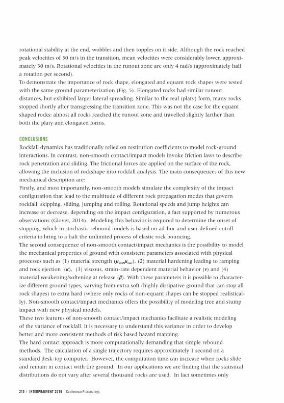
Figure 5: Role of rock shape on rockfall runout. Equant shaped rocks have, in general, the farthest runout distances. However, the real plate-shaped rock can also propagate large distances when it attains “wheel-rolling” modes.
210 | INTERPRAEVENT 2016 – Conference Proceedings
rotational stability at the end, wobbles and then topples on it side. Although the rock reached
peak velocities of 50 m/s in the transition, mean velocities were considerably lower, approxi-
mately 30 m/s. Rotational velocities in the runout zone are only 4 rad/s (approximately half
a rotation per second).
To demonstrate the importance of rock shape, elongated and equant rock shapes were tested
with the same ground parameterization (Fig. 5). Elongated rocks had similar runout
distances, but exhibited larger lateral spreading. Similar to the real (platy) form, many rocks
stopped shortly after transgressing the transition zone. This was not the case for the equant
shaped rocks: almost all rocks reached the runout zone and travelled slightly farther than
both the platy and elongated forms.
CONCLUSIONSRockfall dynamics has traditionally relied on restitution coefficients to model rock-ground
interactions. In contrast, non-smooth contact/impact models invoke friction laws to describe
rock penetration and sliding. The frictional forces are applied on the surface of the rock,
allowing the inclusion of rockshape into rockfall analysis. The main consequences of this new
mechanical description are:
Firstly, and most importantly, non-smooth models simulate the complexity of the impact
configuration that lead to the multitude of different rock propagation modes that govern
rockfall: skipping, sliding, jumping and rolling. Rotational speeds and jump heights can
increase or decrease, depending on the impact configuration, a fact supported by numerous
observations (Glover, 2014). Modeling this behavior is required to determine the onset of
stopping, which in stochastic rebound models is based on ad-hoc and user-defined cutoff
criteria to bring to a halt the unlimited process of elastic rock bouncing.
The second consequence of non-smooth contact/impact mechanics is the possibility to model
the mechanical properties of ground with consistent parameters associated with physical
processes such as (1) material strength (μmin,μmax), (2) material hardening leading to ramping
and rock ejection (κ), (3) viscous, strain-rate dependent material behavior (ν) and (4)
material weakening/softening at release (β). With these parameters it is possible to character-
ize different ground types, varying from extra soft (highly dissipative ground that can stop all
rock shapes) to extra hard (where only rocks of non-equant shapes can be stopped realistical-
ly). Non-smooth contact/impact mechanics offers the possibility of modeling tree and stump
impact with new physical models.
These two features of non-smooth contact/impact mechanics facilitate a realistic modeling
of the variance of rockfall. It is necessary to understand this variance in order to develop
better and more consistent methods of risk based hazard mapping.
The hard contact approach is more computationally demanding that simple rebound
methods. The calculation of a single trajectory requires approximately 1 second on a
standard desk-top computer. However, the computation time can increase when rocks slide
and remain in contact with the ground. In our applications we are finding that the statistical
distributions do not vary after several thousand rocks are used. In fact sometimes only
INTERPRAEVENT 2016 – Conference Proceedings | 211
500 rocks are needed to obtain stable statistical values. For single slope domains the
computational time is therefore not prohibitative; for large scale hazard mapping shadow
angle methods will continue to provide the best computation times for large area analysis.
The application of non-smooth contact/impact mechanics to the rockfall problem is now in its
initial phase. Even at this stage, however, we believe the future impact on rockfall science,
engineering and practice will be significant. One development that we are observing is an
increased interest in rockfall experiments and examination of rockfall events in the field.
Experimental measurements (e.g.to obtain rotational speed as a function of ground type) and
field observations (e.g. documentation of scar lengths, rock shapes and jump lengths) can be
used directly to calibrate non-smooth model parameters. Key is the modeling of rock
jumping, rolling and sliding in three-dimensional terrain without introducing stochastic and
non-physical rebound coefficients.
REFERENCES- Dorren, L. K. (2003). A review of rockfall mechanics and modeling approaches.
Progress in Physical Geography, 27(1), 67-87.
- Leine, R. et al. (2015). Simulation of rockfall trajectories with consideration of rock shape,
Multibody Syst Dyn (2014) 32:241–271, DOI 10.1007/s11044-013-9393-4.
- Schweizer, A. (2015). Ein nichtglattes mechanisches Modell für Steinschlag, Dissertation,
ETH Zürich, Switzerland.
- Glover, J. (2014). Rock-shape and its role in rockfall dynamics, Doctoral Thesis,
Durham University.
- Christen, M. et al. (2012). Integral hazard management using a unified software
environment: numerical simulation tool „RAMMS“ for gravitational natural hazards.
In: G. - Koboltschnig, J. Hübl and J. Braun (Editors), Interpraevent, pp. 77 - 86.
Volkwein et al. (2011). Rockfall characterisation and structural protection-a review,
Natural Hazards and Earth System Sciences, 11.
- An, B. and D. Tannant (2007), Discrete element method contact model for dynamic
simulation of inelastic rock impact, Computers & Geosciences 33 (2007) 513–521.
Thoeni, K. et al., (2014), A 3D discrete element modelling approach for rockfall analysis with
drapery systems, International Journal of Rock Mechanics and Mining Sciences, 68, 107-119.
Recommended