GeneralSpecifications
Model AR-SA, AR-HA, AR-TC, AR-RT, AR-LP, AR-HP, AR-SP, AR-SY, AR-PS, AR-PH, AR-PW, AR1-B2, AR1-D6
ArresterGS 77M02A01-01EN
GS 77M02A01-01EN©Copyright Nov. 2010
5th Edition Sep.16, 2015
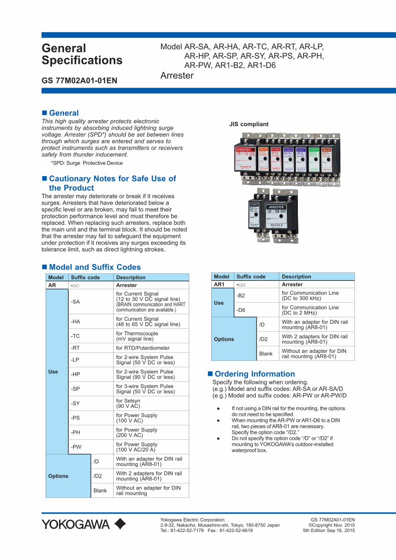
GeneralThis high quality arrester protects electronic instruments by absorbing induced lightning surge voltage. Arrester (SPD*) should be set between lines through which surges are entered and serves to protect instruments such as transmitters or receivers safely from thunder inducement.
*SPD: Surge Protective Device
Cautionary Notes for Safe Use of the Product
The arrester may deteriorate or break if it receives surges. Arresters that have deteriorated below a specific level or are broken, may fail to meet their protection performance level and must therefore be replaced. When replacing such arresters, replace both the main unit and the terminal block. It should be noted that the arrester may fail to safeguard the equipment under protection if it receives any surges exceeding its tolerance limit, such as direct lightning strokes.
ModelandSuffixCodesModel Suffixcode DescriptionAR - Arrester
Use
-SAfor Current Signal(12 to 30 V DC signal line)(BRAIN communication and HART communication are available.)
-HA for Current Signal(48 to 65 V DC signal line)
-TC for Thermocouple(mV signal line)
-RT for RTD/Potentiometer
-LP for 2-wire System Pulse Signal (50 V DC or less)
-HP for 2-wire System Pulse Signal (90 V DC or less)
-SP for 3-wire System Pulse Signal (50 V DC or less)
-SY for Selsyn(90 V AC)
-PS for Power Supply(100 V AC)
-PH for Power Supply(200 V AC)
-PW for Power Supply(100 V AC/20 A)
Options
/D With an adapter for DIN rail mounting (AR8-01)
/D2 With 2 adapters for DIN rail mounting (AR8-01)
Blank Without an adapter for DIN rail mounting
Model Suffixcode DescriptionAR1 - Arrester
Use-B2 for Communication Line
(DC to 300 kHz)
-D6 for Communication Line(DC to 2 MHz)
Options
/D With an adapter for DIN rail mounting (AR8-01)
/D2 With 2 adapters for DIN rail mounting (AR8-01)
Blank Without an adapter for DIN rail mounting (AR8-01)
Ordering InformationSpecify the following when ordering.(e.g.) Model and suffix codes: AR-SA or AR-SA/D(e.g.) Model and suffix codes: AR-PW or AR-PW/D
If not using a DIN rail for the mounting, the options do not need to be specified.
When mounting the AR-PW or AR1-D6 to a DIN rail, two pieces of AR8-01 are necessary. Specify the option code “/D2.”
Do not specify the option code “/D” or “/D2” if mounting to YOKOGAWA's outdoor-installed waterproof box.
JIS compliant
Yokogawa Electric Corporation2-9-32, Nakacho, Musashino-shi, Tokyo, 180-8750 JapanTel.: 81-422-52-7179 Fax.: 81-422-52-6619
2
All Rights Reserved. Copyright © 2010, Yokogawa Electric Corporation GS 77M02A01-01EN Sep.16, 2015-00
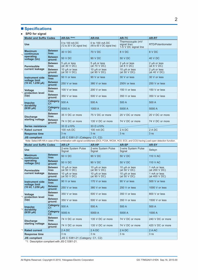
Specifications SPDforsignal
ModelandSuffixCodes AR-SA (Note) AR-HA AR-TC AR-RT
Use 0 to 100 mA DC(12 to 30 V DC signal line)
0 to 100 mA DC(48 to 65 V DC signal line)
Thermocouple (mV signal line)1-5 V DC signal line
RTD/Potentiometer
*1
Maximumcontinuous operating voltage (Uc)
Between lines 30 V DC 70 V DC 8 V DC 8 V DC
Between ground: 50 V DC 90 V DC 50 V DC 40 V DC
Permissible current leakage
Between lines
5 µA or less (at 30 V DC)
5 μA or less (at 70 V DC)
2 μA or less (at 8 V DC)
2 µA or less (at 8 V DC)
Between ground:
10 μA or less (at 50 V DC)
10 μA or less (at 90 V DC)
10 μA or less (at 50 V DC)
2 µA or less (at 40 V DC)
Instrument side voltage limit(10 kV, 1.2/50 µA)
Between lines 50 V or less 90 V or less 30 V or less 30 V or less
Between ground: 250 V or less 380 V or less 250V or less 250 V or less
*1Voltage protection level (Up)
Between lines 100 V or less 200 V or less 150 V or less 150 V or less
Between ground: 350 V or less 500 V or less 350 V or less 350 V or less
*1Impulse durability (8/20 µA)
Category C1 500 A 500 A 500 A 500 A
Category C2 5000 A 1000 A 5000 A 5000 A
Discharge starting voltage
Between lines 35 V DC or more 75 V DC or more 20 V DC or more 20 V DC or more
Between ground: 74 V DC or more 135 V DC or more 74 V DC or more 74 V DC or more
Series resistance 33 Ω ±10% 33 Ω ±10%*1 Rated current 100 mA DC 100 mA DC 2 A DC 2 A DC
Response time 3 ns 3 ns 3 ns 3 nsJIS compliant JIS C 5381-21 (Category: C1, C2)Note: Select AR-HA in case of the combination with signal conditioners (DC0, FC0A, WC0A, HC0, EC0, and CC0) having Load-open detection function.
ModelandSuffixCodes AR-LP AR-HP AR-SP AR-SY
Use 2-wire System Pulse Signal
2-wire System Pulse Signal
3-wire System Pulse Signal Selsyn
*1
Maximumcontinuous operating voltage (Uc)
Between lines 50 V DC 90 V DC 50 V DC 110 V AC
Between ground: 50 V DC 90 V DC 50 V DC 110 V AC
Permissible current leakage
Between lines
10 μA or less (at 50 V DC)
10 μA or less (at 90 V DC)
10 μA or less (at 50 V DC)
1 mA or less (at 200 V DC)
Between ground:
10 μA or less (at 50 V DC)
10 μA or less (at 90 V DC)
10 μA or less (at 50 V DC)
1 mA or less (at 400 V DC)
Instrument side voltage limit(10 kV, 1.2/50 µA)
Between lines 90 V or less 170 V or less 90 V or less 500 V or less
Between ground: 250 V or less 380 V or less 250 V or less 1000 V or less
*1Voltage protection level (Up)
Between lines 350 V or less 500 V or less 350 V or less 800 V or less
Between ground: 350 V or less 500 V or less 350 V or less 1500 V or less
*1Impulse durability (8/20 µA)
Category C1 500 A 500 A 500 A 500 A
Category C2 5000 A 5000 A 5000 A 1000 A
Discharge starting voltage
Between lines 74 V DC or more 135 V DC or more 74 V DC or more 240 V DC or more
Between ground: 74 V DC or more 135 V DC or more 74 V DC or more 420 V DC or more
*1 Rated current 2 A DC 2 A DC 2 A DC 2 A ACResponse time 3 ns 3 ns 3 ns 3 nsJIS compliant JIS C 5381-21 (Category: C1, C2)*1: Description compliant with JIS C 5381-21.
3
All Rights Reserved. Copyright © 2010, Yokogawa Electric Corporation GS 77M02A01-01EN Sep.16, 2015-00
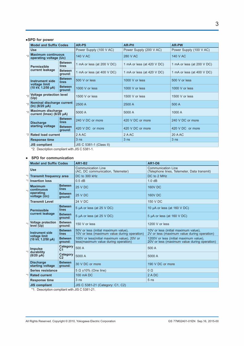
SPDforpowerModelandSuffixCodes AR-PS AR-PH AR-PWUse Power Supply (100 V AC) Power Supply (200 V AC) Power Supply (100 V AC)
*2 Maximumcontinuousoperating voltage (Uc) 140 V AC 280 V AC 140 V AC
Permissible current leakage
Between lines 1 mA or less (at 200 V DC) 1 mA or less (at 420 V DC) 1 mA or less (at 200 V DC)
Between ground: 1 mA or less (at 400 V DC) 1 mA or less (at 420 V DC) 1 mA or less (at 400 V DC)
Instrument side voltage limit(10 kV, 1.2/50 µA)
Between lines 500 V or less 1000 V or less 500 V or less
Between ground: 1000 V or less 1000 V or less 1000 V or less
*2 Voltage protection level (Up) 1500 V or less 1500 V or less 1500 V or less
*2 Nominal discharge current (In) (8/20 µA) 2500 A 2500 A 500 A
*2 Maximumdischargecurrent(Imax)(8/20µA) 5000 A 5000 A 1000 A
Discharge starting voltage
Between lines 240 V DC or more 420 V DC or more 240 V DC or more
Between ground: 420 V DC or more 420 V DC or more 420 V DC or more
*2 Rated load current 2 A AC 2 A AC 20 A ACResponse time 3 ns 3 ns 3 nsJIS compliant JIS C 5381-1 (Class II)*2: Description compliant with JIS C 5381-1.
SPDforcommunicationModelandSuffixCodes AR1-B2 AR1-D6
Use Communication Line(AC, DC communication, Telemeter)
Communication Line(Telephone lines, Telemeter, Data transmit)
*1 Transmit frequency area DC to 300 kHz DC to 2 MHz*1 Insertion loss 0.5 dB 1.0 dB
*1
Maximumcontinuous operating voltage (Uc)
Between lines 25 V DC 160V DC
Between ground: 25 V DC 160V DC
Transmit Level 24 V DC 150 V DC
Permissible current leakage
Between lines 5 μA or less (at 25 V DC) 10 μA or less (at 160 V DC)
Between ground: 5 μA or less (at 25 V DC) 5 μA or less (at 160 V DC)
*1 Voltage protection level (Up)
Between ground: 150 V or less 1200 V or less
Instrument side voltage limit(10 kV, 1.2/50 µA)
Between lines
50V or less (initial maximum value), 10V or less (maximum value during operation)
10V or less (initial maximum value), 2V or less (maximum value during operation)
Between ground:
100V or less(initial maximum value), 20V or less(maximum value during operation)
1200V or less (initial maximum value), 20V or less (maximum value during operation)
*1Impulse durability (8/20 µA)
Category C1 500 A 500 A
Category C2 5000 A 5000 A
Discharge starting voltage
Between ground: 30 V DC or more 190 V DC or more
Series resistance 5 Ω ±10% (One line) 0 Ω*1 Rated current 100 mA DC 2 A DC
Response time 3 ns 5 nsJIS compliant JIS C 5381-21 (Category: C1, C2)*1: Description compliant with JIS C 5381-21.
4
All Rights Reserved. Copyright © 2010, Yokogawa Electric Corporation GS 77M02A01-01EN Sep.16, 2015-00
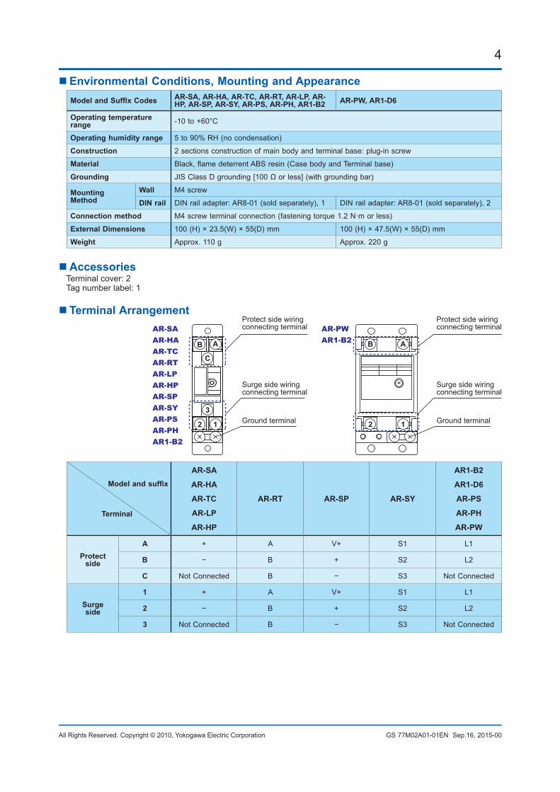
Environmental Conditions, Mounting and AppearanceModelandSuffixCodes AR-SA, AR-HA, AR-TC, AR-RT, AR-LP, AR-
HP, AR-SP, AR-SY, AR-PS, AR-PH, AR1-B2 AR-PW, AR1-D6
Operating temperature range -10 to +60°C
Operating humidity range 5 to 90% RH (no condensation)
Construction 2 sections construction of main body and terminal base: plug-in screw
Material Black, flame deterrent ABS resin (Case body and Terminal base)
Grounding JIS Class D grounding [100 Ω or less] (with grounding bar)
Mounting Method
Wall M4 screw
DIN rail DIN rail adapter: AR8-01 (sold separately), 1 DIN rail adapter: AR8-01 (sold separately), 2
Connection method M4 screw terminal connection (fastening torque 1.2 N·m or less)
ExternalDimensions 100 (H) × 23.5(W) × 55(D) mm 100 (H) × 47.5(W) × 55(D) mm
Weight Approx. 110 g Approx. 220 g
AccessoriesTerminal cover: 2Tag number label: 1
Terminal Arrangement
AB
12
A
C
B
12
3
Surge side wiringconnecting terminal
Protect side wiringconnecting terminal
Ground terminal
Surge side wiringconnecting terminal
Protect side wiringconnecting terminal
Ground terminal
AR-SAAR-HAAR-TCAR-RTAR-LPAR-HPAR-SPAR-SYAR-PSAR-PHAR1-B2
AR-PWAR1-B2
Modelandsuffix
Terminal
AR-SA
AR-HA
AR-TC
AR-LP
AR-HP
AR-RT AR-SP AR-SY
AR1-B2
AR1-D6
AR-PS
AR-PH
AR-PW
Protect side
A + A V+ S1 L1
B − B + S2 L2
C Not Connected B − S3 Not Connected
Surge side
1 + A V+ S1 L1
2 − B + S2 L2
3 Not Connected B − S3 Not Connected
5
All Rights Reserved. Copyright © 2010, Yokogawa Electric Corporation GS 77M02A01-01EN Sep.16, 2015-00
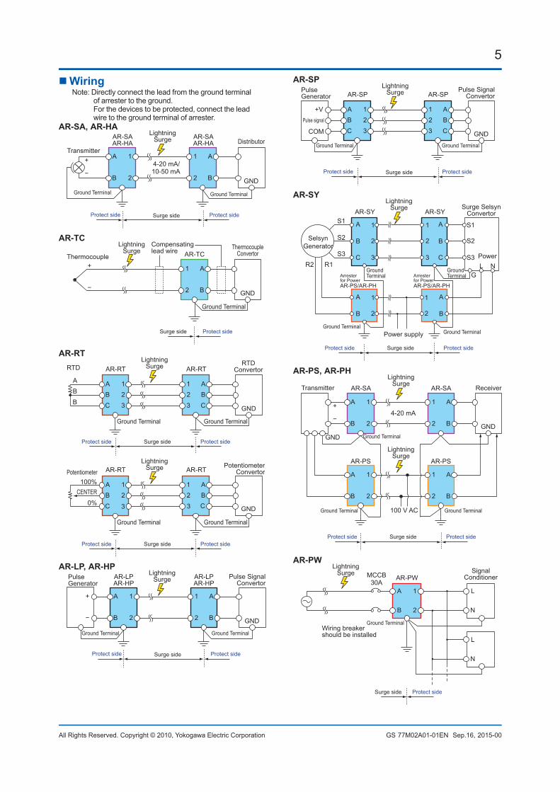
WiringNote: Directly connect the lead from the ground terminal
of arrester to the ground. For the devices to be protected, connect the lead wire to the ground terminal of arrester.
AR-SA, AR-HA
DistributorTransmitter
AR-SAAR-HA
AR-SAAR-HA
LightningSurge
A+
−B
1
2
1
2
A
B GND
4-20 mA/10-50 mA
Ground Terminal Ground Terminal
Protect side Protect sideSurge side
AR-TC
ThermocoupleConvertorThermocouple AR-TC
1
2
A
B GND
Ground Terminal
LightningSurge
Compensatinglead wire
Protect sideSurge side
+
−
AR-RT
AR-RT AR-RT
A
C
1
3
1B 2
3
A2 B
C GND
RTDConvertor
PotentiometerConvertor
RTD
Potentiometer
AR-RT AR-RT
A
C
1
3
1B 2
3
A2 B
C GND
Ground TerminalGround Terminal
Ground TerminalGround Terminal
A
BB
100%CENTER
0%
LightningSurge
LightningSurge
Protect side Protect sideSurge side
Protect side Protect sideSurge side
AR-LP, AR-HP
PulseGenerator
Pulse SignalConvertor
AR-LPAR-HP
AR-LPAR-HP
A
B
1
2
1
2
A
B GND
Ground Terminal Ground Terminal
Protect side Protect sideSurge side
LightningSurge
+
−
AR-SP
AR-SP AR-SP
1
3
A2 B
C GND
A
C
1B 2
3Pulse signal
+V
COM
PulseGenerator
Pulse SignalConvertor
Ground Terminal Ground Terminal
Protect side Protect sideSurge side
LightningSurge
AR-SY
1
Power
AS1
R1R2
S2
S3
AR-SY
B
1
2
C 3
A
B 2
A
Surge SelsynConvertor
SelsynGenerator
B
1
2
C3
S1
S2
S3
GL N
A
B
1
2
Arrester for PowerAR-PS/AR-PH
Arrester for PowerAR-PS/AR-PH
AR-SY
Power supply
LightningSurge
Protect side Protect sideSurge side
Ground Terminal
Ground Terminal
Ground TerminalGround Terminal
AR-PS, AR-PH
ReceiverTransmitter AR-SA AR-SA
A+
−B
1
2
1
2
A
B
A
B
1
2
1
2
A
B
GND
4-20 mA
GND
AR-PS AR-PS
100 V AC
LightningSurge
LightningSurge
Ground TerminalGround Terminal
Ground Terminal
Protect side Protect sideSurge side
AR-PW
A
AR-PWMCCB30A
B
1
2
L
N
L
N
Wiring breaker should be installed
SignalConditioner
Protect sideSurge side
LightningSurge
Ground Terminal
6
All Rights Reserved. Copyright © 2010, Yokogawa Electric Corporation GS 77M02A01-01EN Sep.16, 2015-00
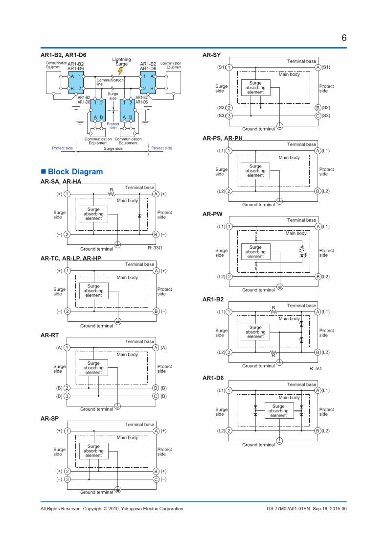
AR1-B2, AR1-D6
CommunicationEquipment
CommunicationEquipment
CommunicationEquipment
AR1-B2AR1-D6
AR1-B2AR1-D6
AR1-B2AR1-D6
AR1-B2AR1-D6
LightningSurge
A
B
1
2
1
A
2
B
1
A
2
B
1
2
A
B
CommunicationEquipment
Protect side
Protectside
Protect side Surge side
Surgeside
Communicationline
Block DiagramAR-SA, AR-HA
Terminal base
Main body
R: 33ΩGround terminal
(+)
B (−)
(+)
(−)
R1
2
A
Surgeabsorbingelement
Surgeside
Protectside
AR-TC, AR-LP, AR-HP
B
1
2
ATerminal base
Main body
Ground terminal
(+)
(−)
(+)
(−)
Surgeabsorbingelement
Surgeside
Protectside
AR-RT
(A)
B (B)
C (B)
(A)
(B)
1
2
(B) 3
ATerminal base
Main body
Ground terminal
Surgeabsorbingelement
Surgeside
Protectside
AR-SP
B
C
1
2
3
A (+)
(+)
(−)
(+)
(+)
(−)
Terminal base
Main body
Ground terminal
Surgeabsorbingelement
Surgeside
Protectside
AR-SY
(S1)
B (S2)
C (S3)
(S1)
(S2)
1
2
(S3) 3
ATerminal base
Main body
Ground terminal
Surgeabsorbingelement
Surgeside
Protectside
AR-PS, AR-PH
(L1)
B (L2)
(L1)
(L2)
1
2
ATerminal base
Main body
Ground terminal
Surgeabsorbingelement
Surgeside
Protectside
AR-PW
B
1
2
A (L1)
(L2)
(L1)
(L2)
Terminal base
Main body
Ground terminal
Surgeabsorbingelement
Surgeside
Protectside
AR1-B2
R: 5Ω
(L1)
B (L2)
(L1)
(L2)
R
R
1
2
ATerminal base
Main body
Ground terminal
Surgeabsorbingelement
Surgeside
Protectside
AR1-D6
(L1)
B (L2)
(L1)
(L2)
1
2
ATerminal base
Main body
Ground terminal
Surgeabsorbingelement
Surgeside
Protectside
7
All Rights Reserved. Copyright © 2010, Yokogawa Electric Corporation GS 77M02A01-01EN Sep.16, 2015-00
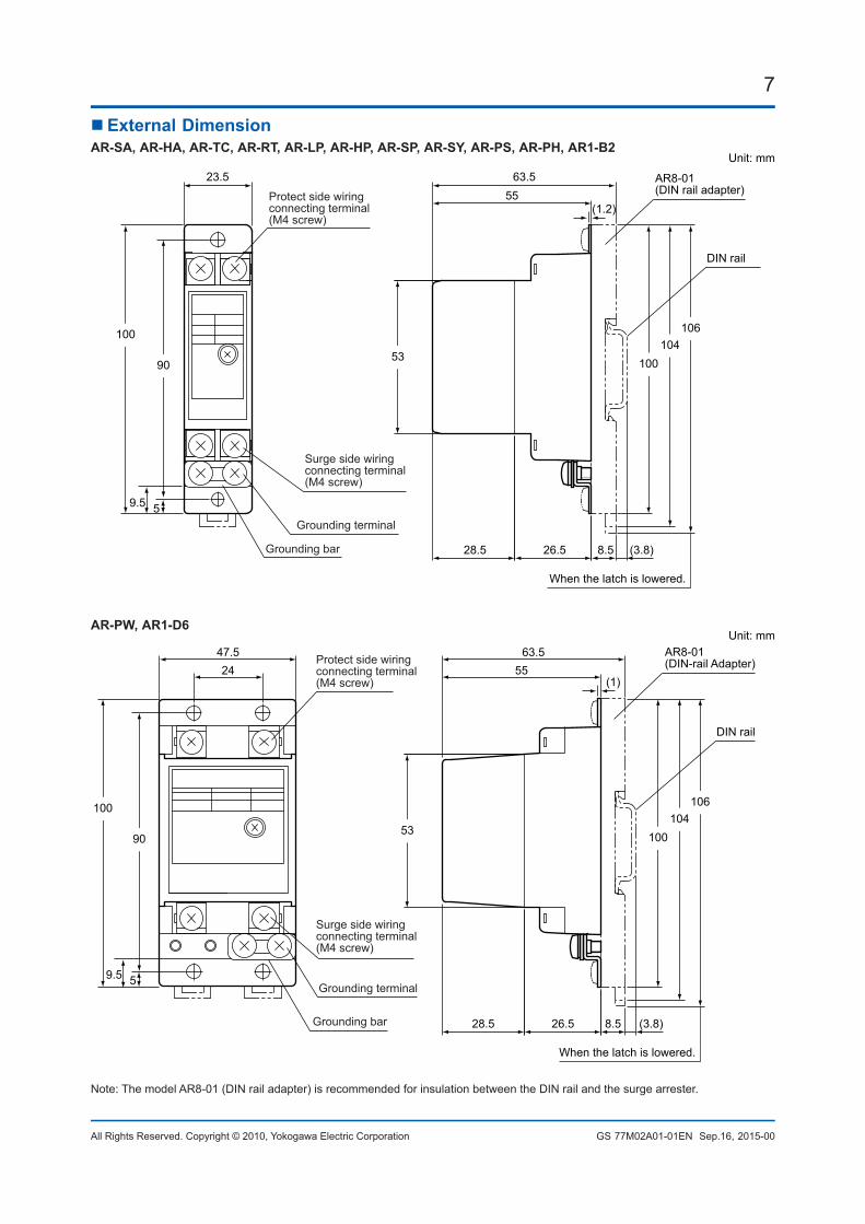
ExternalDimensionAR-SA, AR-HA, AR-TC, AR-RT, AR-LP, AR-HP, AR-SP, AR-SY, AR-PS, AR-PH, AR1-B2
23.5 63.5Unit: mm
55
8.5 (3.8)
When the latch is lowered.
26.528.5
Surge side wiringconnecting terminal(M4 screw)
Protect side wiringconnecting terminal(M4 screw)
Grounding terminal
Grounding bar
9053
100
100104
106
DIN rail
AR8-01(DIN rail adapter)
59.5
(1.2)
AR-PW, AR1-D6
47.524
63.555
8.5 (3.8)26.528.5
9053
100
100104
106
When the latch is lowered.
Surge side wiringconnecting terminal(M4 screw)
Protect side wiringconnecting terminal(M4 screw)
Grounding terminal
Grounding bar
DIN rail
AR8-01(DIN-rail Adapter)
59.5
(1)
Unit: mm
Note: The model AR8-01 (DIN rail adapter) is recommended for insulation between the DIN rail and the surge arrester.
8
All Rights Reserved. Copyright © 2010, Yokogawa Electric Corporation GS 77M02A01-01EN
8<<Contents>> <<Index>>
Sep.16, 2015-00Subject to change without notice.
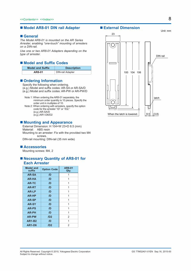
Model AR8-01 DIN rail Adapter
GeneralThe Model AR8-01 is mounted on the AR Series Arrester, enabling “one-touch” mounting of arresters on a DIN-rail. Use one or two AR8-01 Adapters depending on the type of arrester.
ModelandSuffixCodesModelandSuffix Description
AR8-01 DIN-rail Adapter
Ordering InformationSpecify the following when ordering.(e.g.) Model and suffix codes: AR-SA or AR-SA/D(e.g.) Model and suffix codes: AR-PW or AR-PW/D
Note 1: When ordering the AR8-01 separately, the minimum order quantity is 10 pieces. Specify the order unit in multiples of 10.
Note 2: When ordering with arresters, specify the option code for the arrester “/D” or “/D2.” (e.g.) AR-SA/D (e.g.) AR1-D6/D2
Mounting and AppearanceExternal Dimension: H 104×W 23×D 8.5 (mm)Material: ABS resinMounting to an arrester: Fix with the provided two M4
screws.DIN-rail mounting: DIN-rail (35 mm wide)
AccessoriesMounting screws: M4, 2
Necessary Quantity of AR8-01 for Each Arrester
Model and suffix Option Code AR8-01
Qty.AR-SA /D 1AR-HA /D 1AR-TC /D 1AR-RT /D 1AR-LP /D 1AR-HP /D 1AR-SP /D 1AR-SY /D 1AR-PS /D 1AR-PH /D 1AR-PW /D2 2AR1-B2 /D 1AR1-D6 /D2 2
ExternalDimension
When the latch is lowered.
100 104 106
8.5 (3.8)
DIN rail
latch
23Unit: mm
Recommended