2017 Fueltec 955SS
Fueltec Models 955SS Mobile Fuel Tank Cleaning System
Fueltec Systems LLC 828-212-1141
www.fueltecsystems.com
2
2017 Fueltec 955SS
Today’s diesel engines require aircraft quality fuel. Not to many years ago diesel engines were quite simple, not too efficient,
smoked, and burned high sulfur fuel (as much as 5,000 parts per million). The older diesel injection systems only use about 1⁄2 the fuel pressure modern engines do, and older injectors send the fuel through much larger passages. If there was a little moisture in the storage tank, the high sulfur content killed most of the filter clogging bacteria and fungi.
Today’s diesel fuel is ultra-low sulfur (15 parts per million) which allows
bacteria and fungi to grow rapidly if any moisture is in the fuel storage tank.
Today’s diesel engines use high pressure, 27,000 to 35,000 psi fuel
injectors with tiny fuel passages which are easily clogged with dirty fuel and damaged by water.
The days of using grandpa’s old style boat or tractor filters on your diesel
fuel tank are over. The old style filters and water separators that remove 75% to 99% of the
contamination are not good enough for today’s diesel engines.
Magnets and filter-less devices won't clean fuel to ISO 18/16/13 or remove water to 0.05%
Both Caterpillar and Cummins call for fuel to meet or exceed ISO
cleanliness levels of 18/16/13 with a water content of less than 0.05% Fueltec’s systems meet or exceed these ISO levels with a one micron
primary filter, micro-glass filter/coalescer, and Teflon coated stainless steel hydrophobic water separator. Fueltec uses this type of system on aircraft “Jet-A or JP-8 Jet fuel.
3
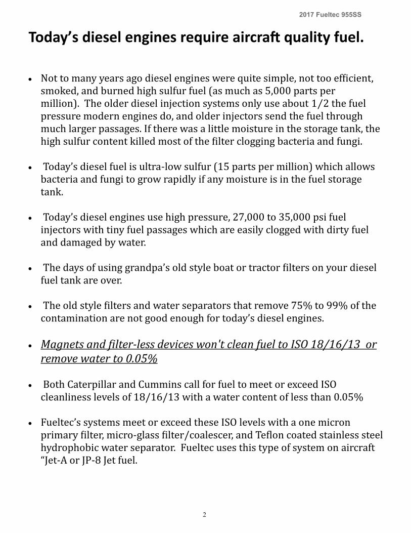
2017 Fueltec 955SS
Removing Water Build up and Contamination from Diesel Fuel and Heating Oil Storage Tanks with Fueltec’s Model
955SS Fuel Polishing System
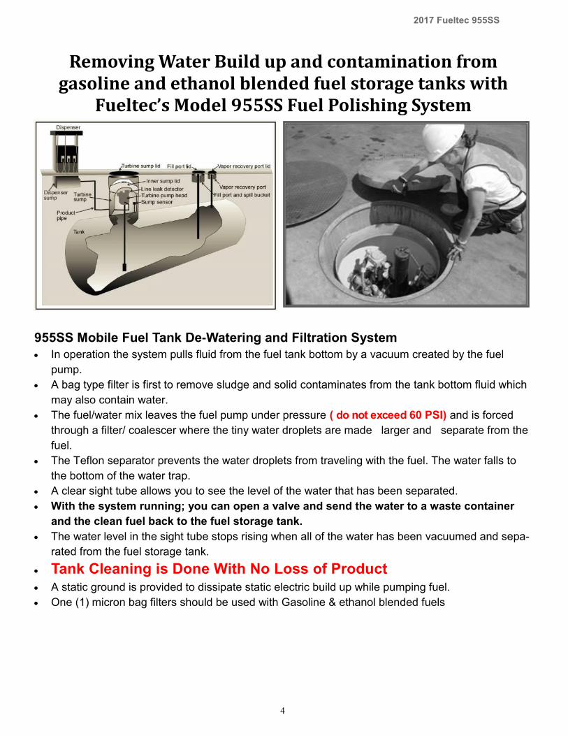
955SS Mobile Fuel Tank De-Watering and Filtration System
In operation the system pulls fluid from the fuel tank bottom by a vacuum created by the fuel
pump.
A bag type filter is first to remove sludge and solid contaminates from the tank bottom fluid which
may also contain water.
The fuel/water mix leaves the fuel pump under pressure ( do not exceed 60 PSI) and is forced
through a filter/ coalescer where the tiny water droplets are made larger and separate from the
fuel.
The Teflon separator prevents the water droplets from traveling with the fuel. The water falls to
the bottom of the water trap.
A clear sight tube allows you to see the level of the water that has been separated.
With the system running; you can open a valve and send the water to a waste container
and the clean fuel back to the fuel storage tank.
The water level in the sight tube stops rising when all of the water has been vacuumed and sepa-
rated from the fuel storage tank.
Tank Cleaning is Done With No Loss of Product A static ground is provided to dissipate static electric build up while pumping fuel.
Five (5) micron bag filters should be used with diesel fuels
4
2017 Fueltec 955SS
Removing Water Build up and contamination from gasoline and ethanol blended fuel storage tanks with
Fueltec’s Model 955SS Fuel Polishing System
955SS Mobile Fuel Tank De-Watering and Filtration System
In operation the system pulls fluid from the fuel tank bottom by a vacuum created by the fuel
pump.
A bag type filter is first to remove sludge and solid contaminates from the tank bottom fluid which
may also contain water.
The fuel/water mix leaves the fuel pump under pressure ( do not exceed 60 PSI) and is forced
through a filter/ coalescer where the tiny water droplets are made larger and separate from the
fuel.
The Teflon separator prevents the water droplets from traveling with the fuel. The water falls to
the bottom of the water trap.
A clear sight tube allows you to see the level of the water that has been separated.
With the system running; you can open a valve and send the water to a waste container
and the clean fuel back to the fuel storage tank.
The water level in the sight tube stops rising when all of the water has been vacuumed and sepa-
rated from the fuel storage tank.
Tank Cleaning is Done With No Loss of Product A static ground is provided to dissipate static electric build up while pumping fuel.
One (1) micron bag filters should be used with Gasoline & ethanol blended fuels

5
2017 Fueltec 955SS
Removing Water Build up and Contamination from Jet A and JP-8 Fuel Storage Tanks with Fueltec’s Model 955SS
Fuel Polishing System
This system is designed for cleaning fuel storage tanks and is not certified to be used for dispensing fuel into aircraft.
955SS Mobile Fuel Tank De-Watering and Filtration System
In operation the system pulls fluid from the fuel tank bottom by a vacuum created by the fuel
pump.
A bag type filter is first to remove sludge and solid contaminates from the tank bottom fluid which
may also contain water.
The fuel/water mix leaves the fuel pump under pressure ( do not exceed 60 PSI) and is forced
through a filter/ coalescer where the tiny water droplets are made larger and separate from the
fuel.
The Teflon separator prevents the water droplets from traveling with the fuel. The water falls to
the bottom of the water trap.
A clear sight tube allows you to see the level of the water that has been separated.
With the system running; you can open a valve and send the water to a waste container
and the clean fuel back to the fuel storage tank.
The water level in the sight tube stops rising when all of the water has been vacuumed and sepa-
rated from the fuel storage tank.
Tank Cleaning is Done With No Loss of Product A static ground is provided to dissipate static electric build up while pumping fuel.
One (1) micron bag filters should be used with Jet A & JP-8 Fuels
CMH HELI-SKIING Canadian Mountain Holidays (CMH), a helicopter skiing company in western Canada owns and maintains thirty 50,000L fuel tanks which require annual cleaning. With Fuel Tec’s 955SS mobile fuel polishing system, removing water build up at the bottom of the tank has nev-er been easier. The 955SS removes the water and sediment with virtually no fuel waste. This saves CMH thousands of dollars each year in waste fuel removal costs. If you are in the business of fuel tank cleaning or fuel maintenance, I highly recommend this unit. Brett Lawrence Fuel Systems Supervisor Canadian Mountain Holidays
6
2017 Fueltec 955SS
WARNING: Read carefully and understand all INSTRUCTIONS before operating. Failure to follow the safety rules and other basic safety precautions may result in serious personal injury, or death.
It is important that you read the entire manual to
become familiar with this product before you begin using it.
This machine is designed for certain applications only. FuelTec Systems cannot be
responsible for issues arising from modification. We strongly recommend this machine is not modified and/or used for
any application other than that for which it was designed. If you have any questions relative to a particular application,
DO NOT use the machine until you have first contacted FuelTec Systems to determine if it can or should be performed
on the product.
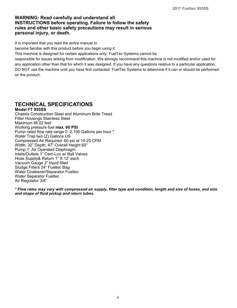
TECHNICAL SPECIFICATIONS Model FT 955SS Chassis Construction Steel and Aluminum Brite Tread Filter Housings Stainless Steel Maximum lift 22 feet Working pressure fuel max. 60 PSI Pump rated flow rate range 0 -2,100 Gallons per hour * Water Trap two (2) Gallons US Compressed Air Required: 60 psi at 10-25 CFM Width: 32” Depth: 47” Overall Height 60” Pump 1” Air Operated Diaphragm Inlets/Outlets 1” Cam-Loc w/ Ball Valves Hose Supply& Return 1” X 12’ each Vacuum Gauge 2” liquid filled Sludge Filters 24” Fueltec Bag Water Coalescer/Separator Fueltec Water Separator Fueltec Air Regulator 3/8” * Flow rates may vary with compressed air supply, filter type and condition, length and size of hoses, and size and shape of fluid pickup and return tubes.
7
2017 Fueltec 955SS
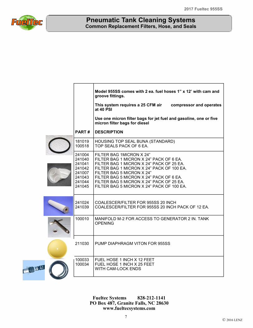
Pneumatic Tank Cleaning Systems Common Replacement Filters, Hose, and Seals
Fueltec Systems 828-212-1141 PO Box 487, Granite Falls, NC 28630
www.fueltecsystems.com
© 2016 LENZ
PART #
Model 955SS comes with 2 ea. fuel hoses 1” x 12’ with cam and groove fittings. This system requires a 25 CFM air compressor and operates at 40 PSI Use one micron filter bags for jet fuel and gasoline, one or five micron filter bags for diesel DESCRIPTION
181019 100518
HOUSING TOP SEAL BUNA (STANDARD) TOP SEALS PACK OF 6 EA.
241004 241040 241041 241042 241007 241043 241044 241045
FILTER BAG 1MICRON X 24” FILTER BAG 1 MICRON X 24” PACK OF 6 EA. FILTER BAG 1 MICRON X 24” PACK OF 25 EA. FILTER BAG 1 MICRON X 24” PACK OF 100 EA. FILTER BAG 5 MICRON X 24” FILTER BAG 5 MICRON X 24” PACK OF 6 EA. FILTER BAG 5 MICRON X 24” PACK OF 25 EA. FILTER BAG 5 MICRON X 24” PACK OF 100 EA.
241024 241039
COALESCER/FILTER FOR 955SS 20 INCH COALESCER/FILTER FOR 955SS 20 INCH PACK OF 12 EA.
100010 MANIFOLD M-2 FOR ACCESS TO GENERATOR 2 IN. TANK OPENING
211030
PUMP DIAPHRAGM VITON FOR 955SS
100033 100034
FUEL HOSE 1 INCH X 12 FEET FUEL HOSE 1 INCH X 25 FEET WITH CAM-LOCK ENDS

8
2017 Fueltec 955SS
INTENDED USE AND OPERATING PRINCIPAL
This System is designed to be used with diesel fuel, gasoline, jet fuel, heating oil, ker-
osene, and ethanol blended fuels for removing water and other contaminants from fuel
tanks.
The System has three modes of operation:
1. Bulk Fluid Transfer without Water Separation or Filtration is used when several
inches of water are measured on the tank bottom. This water can be pumped directly into
a container without wasting filters or having to empty the Separator water trap.
2. Fuel/Water Separation and Filtration mode is used to separate the remaining water
and filter the fuel after the bulk water has been removed.
3. Filtration without Water Separation can be done at a higher flow rate than with water
separation. Generally used to remove particulate in suspension after water separation.
955SS Mobile Fuel Tank De-Watering and Filtration System
In operation the system pulls fluid from the fuel tank bottom by a vacuum created by the
fuel pump.
A bag type filter is first to remove sludge and solid contaminates from the tank bottom fluid
which may also contain water.
The fuel/water mix leaves the fuel pump under pressure ( do not exceed 40 PSI) and is
forced through a filter/ coalescer where the tiny water droplets are made larger and sep-
arate from the fuel.
The Teflon separator prevents the water droplets from traveling with the fuel. The water
falls to the bottom of the water trap.
A clear sight tube allows you to see the level of the water that has been separated.
With the system running; you can open a valve and send the water to a waste con-
tainer and the clean fuel back to the fuel storage tank.
The water level in the sight tube stops rising when all of the water has been vacuumed and
separated from the fuel storage tank.
Tank Cleaning is Done With No Loss of Product
FEATURES Stainless steel filter housings to resist the acids found in today's diesel and
ethanol blended gasoline. Filtration down to one micron, water removal to less than 100 parts per
million. Exceeds ISO particle code of 18/16/13 to meet engine manufacturers clean
fuel requirements. Air operated diaphragm fuel pump intrinsically safe for all fuels.
9
2017 Fueltec 955SS
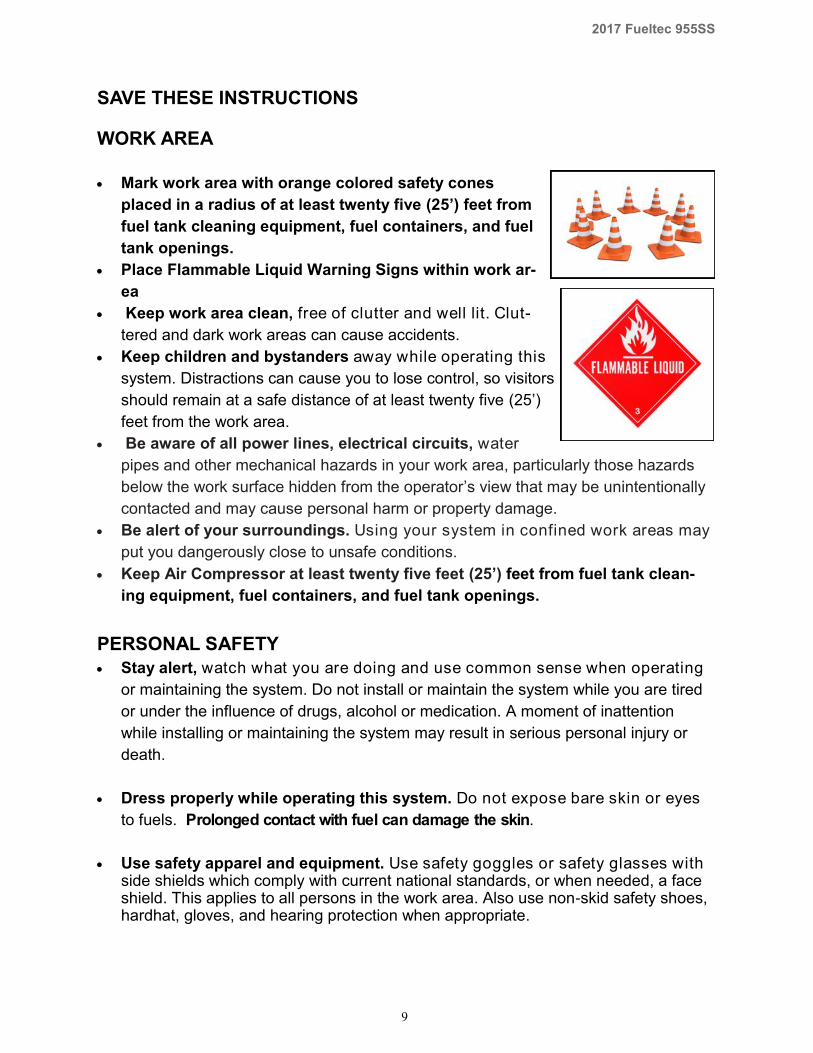
SAVE THESE INSTRUCTIONS WORK AREA
Mark work area with orange colored safety cones
placed in a radius of at least twenty five (25’) feet from
fuel tank cleaning equipment, fuel containers, and fuel
tank openings.
Place Flammable Liquid Warning Signs within work ar-
ea
Keep work area clean, free of clutter and well lit. Clut-
tered and dark work areas can cause accidents.
Keep children and bystanders away while operating this
system. Distractions can cause you to lose control, so visitors
should remain at a safe distance of at least twenty five (25’)
feet from the work area.
Be aware of all power lines, electrical circuits, water
pipes and other mechanical hazards in your work area, particularly those hazards
below the work surface hidden from the operator’s view that may be unintentionally
contacted and may cause personal harm or property damage.
Be alert of your surroundings. Using your system in confined work areas may
put you dangerously close to unsafe conditions.
Keep Air Compressor at least twenty five feet (25’) feet from fuel tank clean-
ing equipment, fuel containers, and fuel tank openings.
PERSONAL SAFETY
Stay alert, watch what you are doing and use common sense when operating
or maintaining the system. Do not install or maintain the system while you are tired
or under the influence of drugs, alcohol or medication. A moment of inattention
while installing or maintaining the system may result in serious personal injury or
death.
Dress properly while operating this system. Do not expose bare skin or eyes
to fuels. Prolonged contact with fuel can damage the skin.
Use safety apparel and equipment. Use safety goggles or safety glasses with side shields which comply with current national standards, or when needed, a face shield. This applies to all persons in the work area. Also use non-skid safety shoes, hardhat, gloves, and hearing protection when appropriate.
10
2017 Fueltec 955SS
FUEL TANK SAFETY
Purge fuel tank (fill airspace inside the tank between any fuel and the top of
the tank) with argon or CO2 prior to drilling or sawing holes that penetrate the
tank to minimize the risk of explosion.
Maintain a purged condition while installing fittings on a fuel tank.
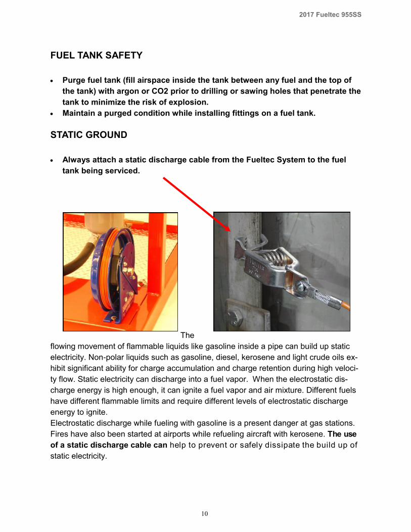
STATIC GROUND
Always attach a static discharge cable from the Fueltec System to the fuel
tank being serviced.
The
flowing movement of flammable liquids like gasoline inside a pipe can build up static
electricity. Non-polar liquids such as gasoline, diesel, kerosene and light crude oils ex-
hibit significant ability for charge accumulation and charge retention during high veloci-
ty flow. Static electricity can discharge into a fuel vapor. When the electrostatic dis-
charge energy is high enough, it can ignite a fuel vapor and air mixture. Different fuels
have different flammable limits and require different levels of electrostatic discharge
energy to ignite.
Electrostatic discharge while fueling with gasoline is a present danger at gas stations.
Fires have also been started at airports while refueling aircraft with kerosene. The use
of a static discharge cable can help to prevent or safely dissipate the build up of
static electricity.
11
2017 Fueltec 955SS
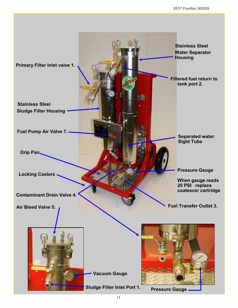
Drip Pan
Filtered fuel return to tank port 2.
Primary Filter Inlet valve 1.
Fuel Transfer Outlet 3.
Contaminant Drain Valve 4.
Vacuum Gauge
Sludge Filter Housing
Fuel Pump Air Valve 7. Separated water Sight Tube
Air Bleed Valve 5.
Water Separator Housing
Pressure Gauge When gauge reads 20 PSI replace coalescer cartridge
Sludge Filter Inlet Port 1. Pressure Gauge
Stainless Steel
Stainless Steel
Locking Casters
12
2017 Fueltec 955SS
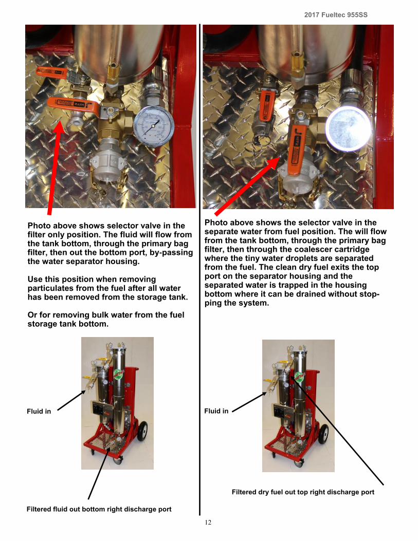
Photo above shows selector valve in the filter only position. The fluid will flow from the tank bottom, through the primary bag filter, then out the bottom port, by-passing the water separator housing. Use this position when removing particulates from the fuel after all water has been removed from the storage tank. Or for removing bulk water from the fuel storage tank bottom.
Photo above shows the selector valve in the separate water from fuel position. The will flow from the tank bottom, through the primary bag filter, then through the coalescer cartridge where the tiny water droplets are separated from the fuel. The clean dry fuel exits the top port on the separator housing and the separated water is trapped in the housing bottom where it can be drained without stop-ping the system.
Fluid in
Filtered fluid out bottom right discharge port
Fluid in
Filtered dry fuel out top right discharge port
13
2017 Fueltec 955SS
Typical Fuel Tank De-Watering and Filtration: Underground and Aboveground Fuel Storage Tanks:
Remove cap or fitting to access tank bottom.
Test for high (2” +) bulk water level with a Fueltec Sampler.
Set the System selector valve to filter only position to remove all but the last inch of
bulk water from the tank.
Attach a fluid pickup tube to the systems supply hose and lower to the tank bottom
through a tank opening.
Connect supply hose to system’s primary bag filter housing.
Connect return hose to system’s bottom right discharge port and a waste container.
Pump out bulk water.
Set the System selector valve to Separate Water position.
Operate the system and observe the separated water level in the water trap.
Empty the water trap as the system is running; stop operation when water is no
longer accumulating in the trap.
If suspended particulates are observed in the sight tube after water has been
removed; Set the System Mode to Filter only.
Use 1 or 5 micron filters for diesel and 1 micron filters for gasoline, jet fuel, &
ethanol blends.
Operate system until the fuel is clear.

14
2017 Fueltec 955SS
Air Bleed Valve 6. Swing Bolt Eye Nut (hand tighten)
Primary Filter inlet valve 1.
Vacuum Gauge When gauge reads 15 Hg. Replace bag filter
Sludge Filter inlet port 1.
Sludge Filter Cover
WARNING: Set air pressure regulator not to exceed forty (40) psi at any time Fuel Pump Air Valve
15
2017 Fueltec 955SS
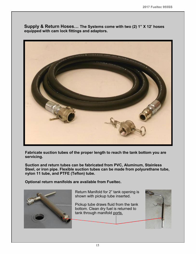
Supply & Return Hoses… The Systems come with two (2) 1” X 12’ hoses equipped with cam lock fittings and adaptors.
Fabricate suction tubes of the proper length to reach the tank bottom you are servicing. Suction and return tubes can be fabricated from PVC, Aluminum, Stainless Steel, or iron pipe. Flexible suction tubes can be made from polyurethane tube, nylon 11 tube, and PTFE (Teflon) tube. Optional return manifolds are available from Fueltec.
Return Manifold for 2” tank opening is shown with pickup tube inserted. Pickup tube draws fluid from the tank bottom. Clean dry fuel is returned to tank through manifold ports.
16
2017 Fueltec 955SS
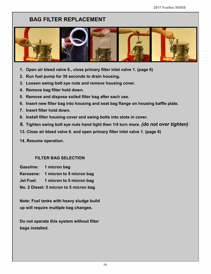
1. Open air bleed valve 6., close primary filter inlet valve 1. (page 6)
2. Run fuel pump for 30 seconds to drain housing.
3. Loosen swing bolt eye nuts and remove housing cover.
4. Remove bag filter hold down.
5. Remove and dispose soiled filter bag after each use.
6. Insert new filter bag into housing and seat bag flange on housing baffle plate.
7. Insert filter hold down.
8. Install filter housing cover and swing bolts into slots in cover.
9. Tighten swing bolt eye nuts hand tight then 1/4 turn more. (do not over tighten)
13. Close air bleed valve 6. and open primary filter inlet valve 1. (page 6) 14. Resume operation.
BAG FILTER REPLACEMENT
FILTER BAG SELECTION
Gasoline: 1 micron bag
Kerosene: 1 micron to 5 micron bag
Jet Fuel: 1 micron to 5 micron bag
No. 2 Diesel: 5 micron to 5 micron bag
Note: Fuel tanks with heavy sludge build
up will require multiple bag changes.
Do not operate this system without filter
bags installed.

17
2017 Fueltec 955SS
Coalescer and Separator Replacement
1. Close fuel pump valve and shut off air supply to system.
2. Open air bleed valve 5., open contaminant drain valve for one minute then close both
valves.
3. Loosen swing bolt eye nuts and remove housing cover.
4. Loosen 3/8” hex separator retaining nut.
5. Remove Separator cartridge. (coalescer may come with it)
6. Apply Vaseline to new coalescer o-rings and insert coalescer into separator.
7. Insert coalescer and separator into housing until 3/8” tie-rod protrudes through top of
separator.
8. Install 3/8” o-ring, washer, and hex nut onto tie-rod and tighten to 5 ft/lbs.
9. Install housing cover, swing bolts into place and hand tighten eye nuts then 1/4 turn
more. ( caution: Do not over tighten eye nuts)
10. Resume operation.
Water Separator Filter/ Coalescer
18
2017 Fueltec 955SS
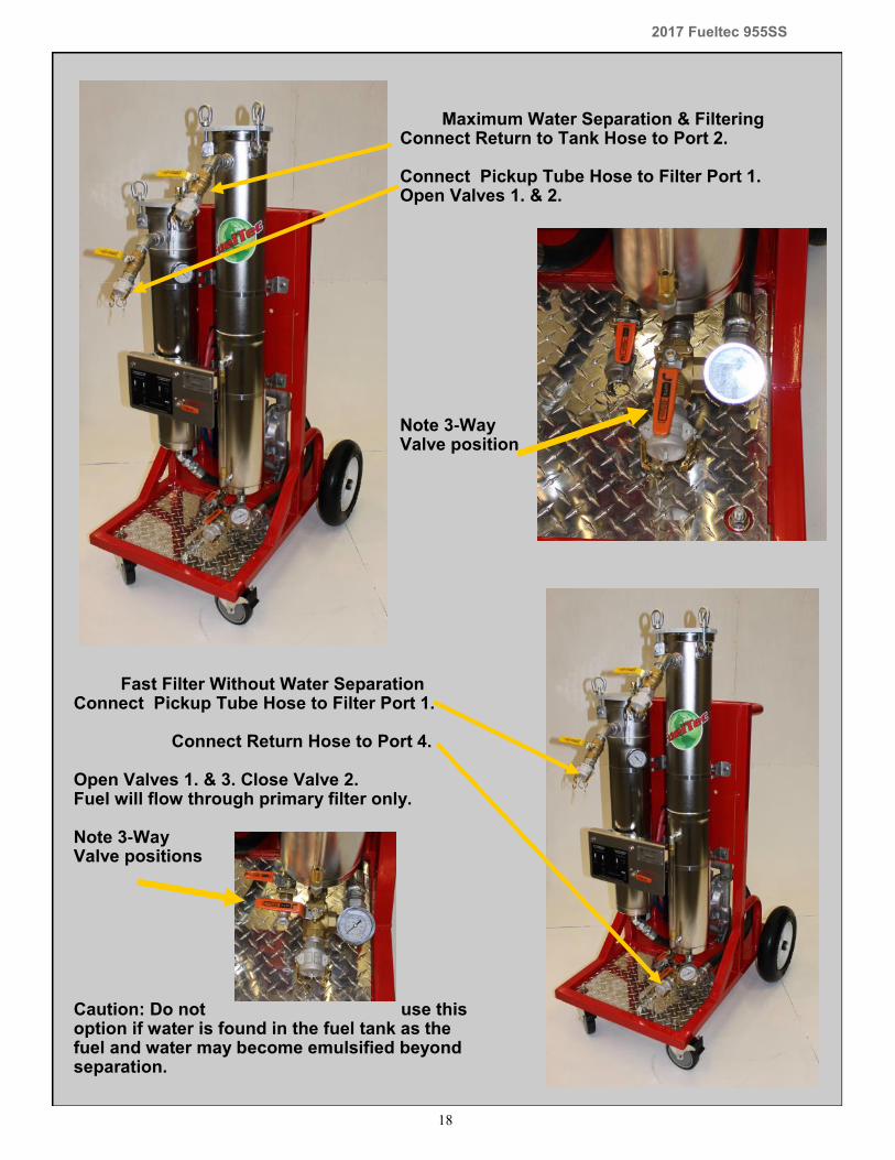
Maximum Water Separation & Filtering Connect Return to Tank Hose to Port 2. Connect Pickup Tube Hose to Filter Port 1. Open Valves 1. & 2. Note 3-Way Valve position
Fast Filter Without Water Separation Connect Pickup Tube Hose to Filter Port 1. Connect Return Hose to Port 4. Open Valves 1. & 3. Close Valve 2. Fuel will flow through primary filter only. Note 3-Way Valve positions Caution: Do not use this option if water is found in the fuel tank as the fuel and water may become emulsified beyond separation.
19
2017 Fueltec 955SS
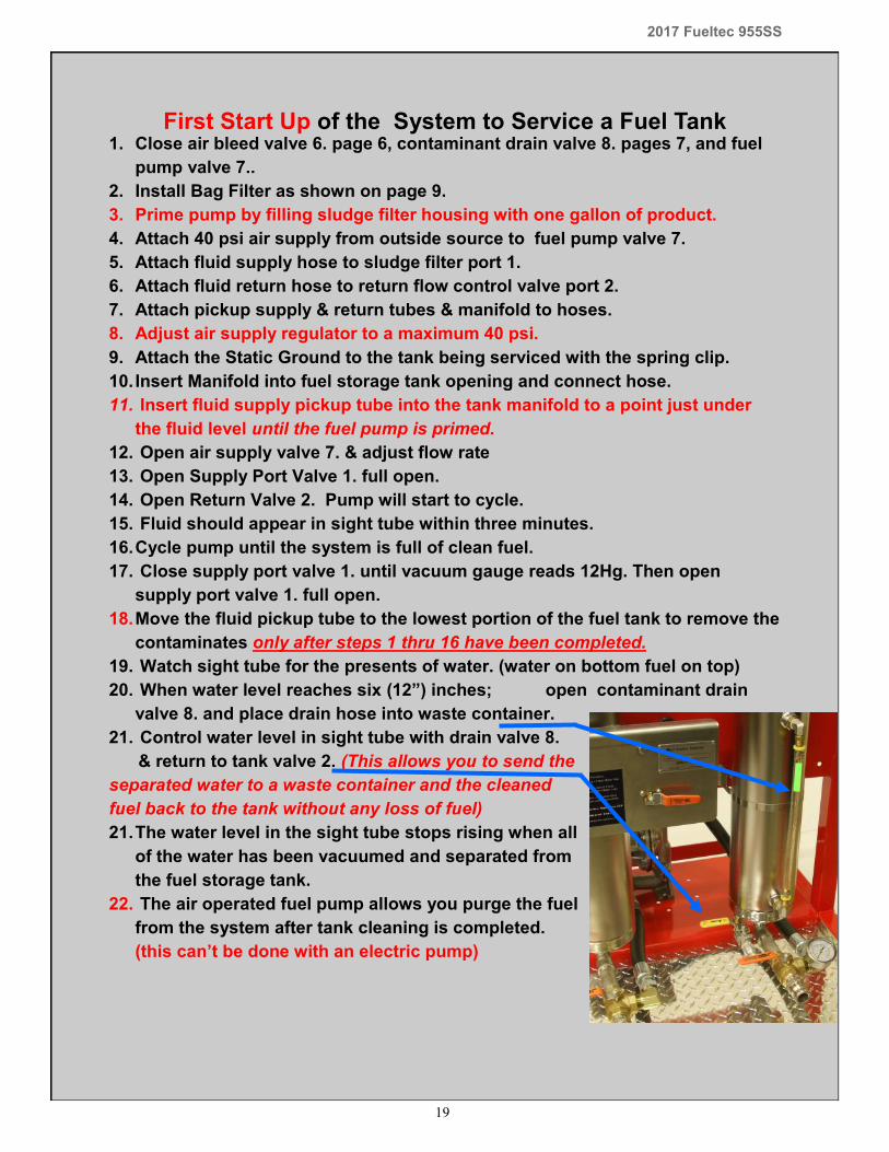
First Start Up of the System to Service a Fuel Tank 1. Close air bleed valve 6. page 6, contaminant drain valve 8. pages 7, and fuel
pump valve 7..
2. Install Bag Filter as shown on page 9.
3. Prime pump by filling sludge filter housing with one gallon of product.
4. Attach 40 psi air supply from outside source to fuel pump valve 7.
5. Attach fluid supply hose to sludge filter port 1.
6. Attach fluid return hose to return flow control valve port 2.
7. Attach pickup supply & return tubes & manifold to hoses.
8. Adjust air supply regulator to a maximum 40 psi.
9. Attach the Static Ground to the tank being serviced with the spring clip.
10. Insert Manifold into fuel storage tank opening and connect hose.
11. Insert fluid supply pickup tube into the tank manifold to a point just under
the fluid level until the fuel pump is primed.
12. Open air supply valve 7. & adjust flow rate
13. Open Supply Port Valve 1. full open.
14. Open Return Valve 2. Pump will start to cycle.
15. Fluid should appear in sight tube within three minutes.
16. Cycle pump until the system is full of clean fuel.
17. Close supply port valve 1. until vacuum gauge reads 12Hg. Then open
supply port valve 1. full open.
18. Move the fluid pickup tube to the lowest portion of the fuel tank to remove the
contaminates only after steps 1 thru 16 have been completed.
19. Watch sight tube for the presents of water. (water on bottom fuel on top)
20. When water level reaches six (12”) inches; open contaminant drain
valve 8. and place drain hose into waste container.
21. Control water level in sight tube with drain valve 8.
& return to tank valve 2. (This allows you to send the
separated water to a waste container and the cleaned
fuel back to the tank without any loss of fuel)
21. The water level in the sight tube stops rising when all
of the water has been vacuumed and separated from
the fuel storage tank.
22. The air operated fuel pump allows you purge the fuel
from the system after tank cleaning is completed.
(this can’t be done with an electric pump)
20
2017 Fueltec 955SS
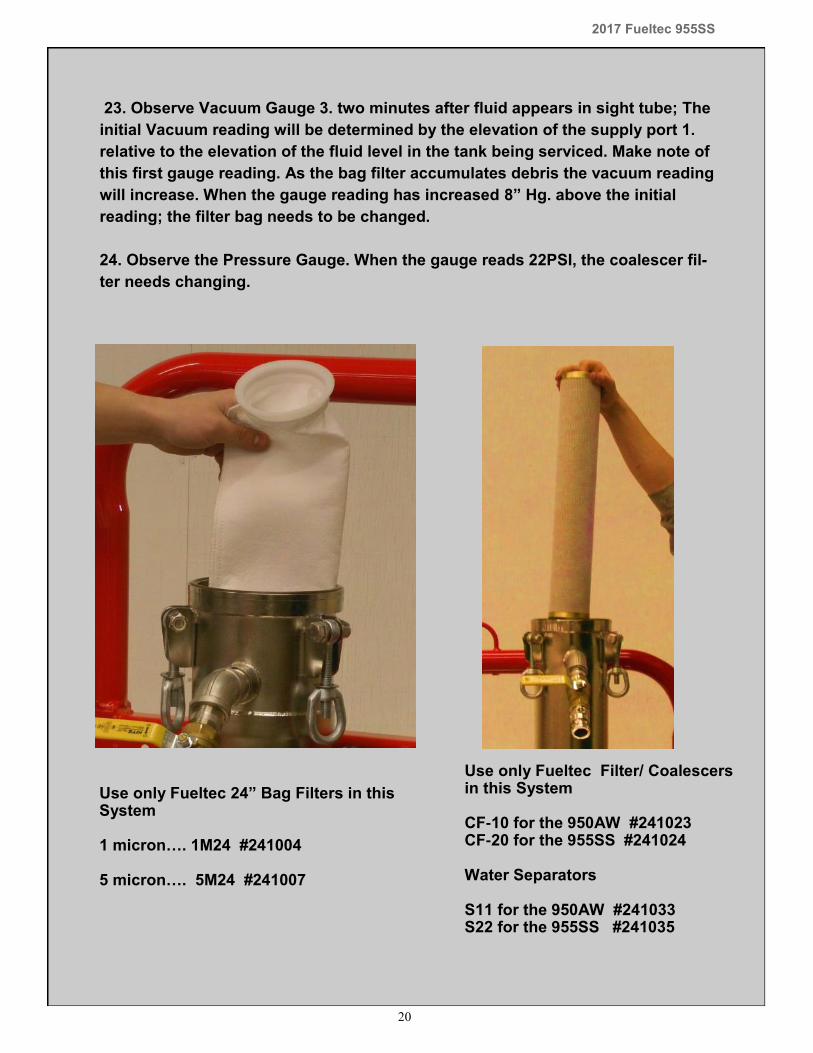
23. Observe Vacuum Gauge 3. two minutes after fluid appears in sight tube; The
initial Vacuum reading will be determined by the elevation of the supply port 1.
relative to the elevation of the fluid level in the tank being serviced. Make note of
this first gauge reading. As the bag filter accumulates debris the vacuum reading
will increase. When the gauge reading has increased 8” Hg. above the initial
reading; the filter bag needs to be changed.
24. Observe the Pressure Gauge. When the gauge reads 22PSI, the coalescer fil-
ter needs changing.
Use only Fueltec 24” Bag Filters in this System 1 micron…. 1M24 #241004 5 micron…. 5M24 #241007
Use only Fueltec Filter/ Coalescers in this System CF-10 for the 950AW #241023 CF-20 for the 955SS #241024 Water Separators S11 for the 950AW #241033 S22 for the 955SS #241035
21
2017 Fueltec 955SS
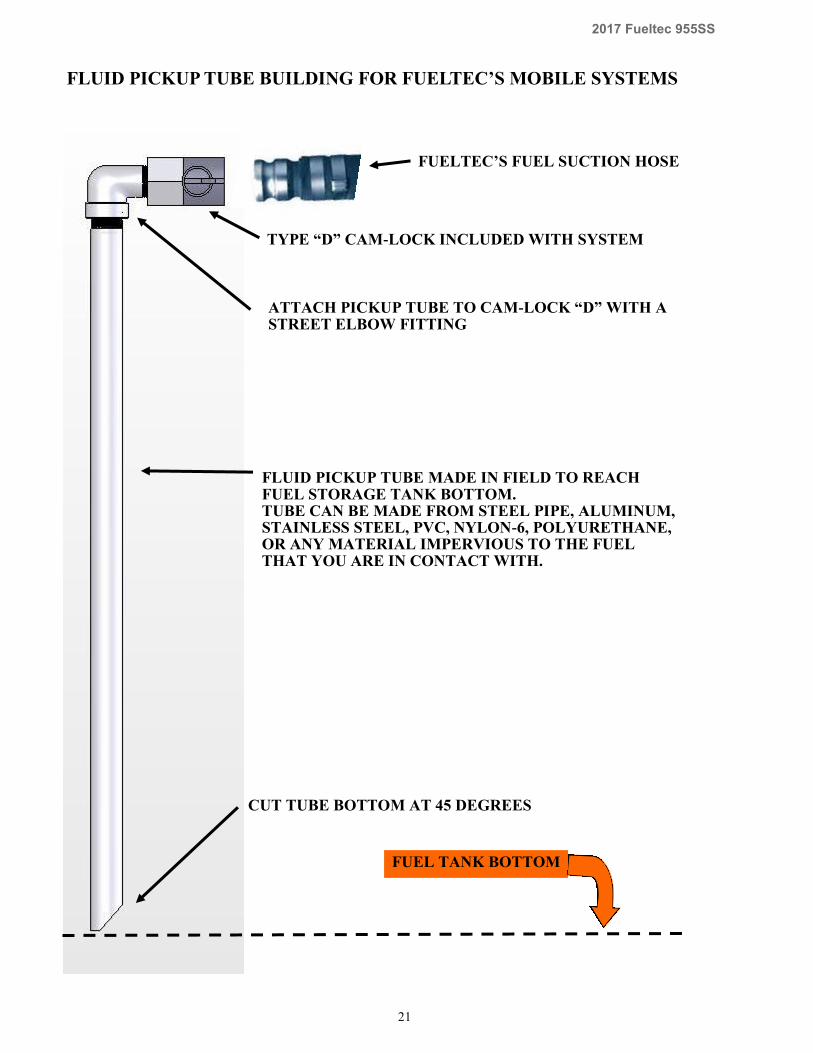
TYPE “D” CAM-LOCK INCLUDED WITH SYSTEM
FUELTEC’S FUEL SUCTION HOSE
FLUID PICKUP TUBE MADE IN FIELD TO REACH FUEL STORAGE TANK BOTTOM. TUBE CAN BE MADE FROM STEEL PIPE, ALUMINUM, STAINLESS STEEL, PVC, NYLON-6, POLYURETHANE, OR ANY MATERIAL IMPERVIOUS TO THE FUEL THAT YOU ARE IN CONTACT WITH.
CUT TUBE BOTTOM AT 45 DEGREES
FUEL TANK BOTTOM
ATTACH PICKUP TUBE TO CAM-LOCK “D” WITH A STREET ELBOW FITTING
FLUID PICKUP TUBE BUILDING FOR FUELTEC’S MOBILE SYSTEMS
22
2017 Fueltec 955SS
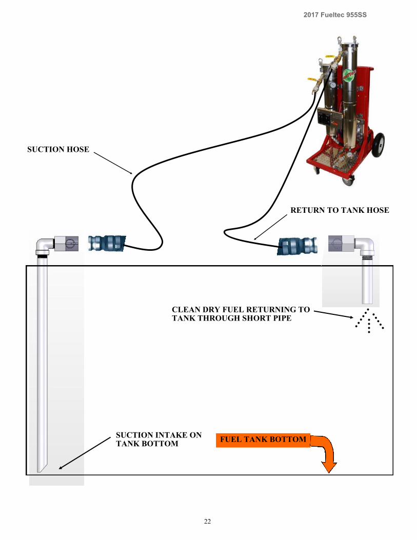
SUCTION HOSE
RETURN TO TANK HOSE
FUEL TANK BOTTOM
CLEAN DRY FUEL RETURNING TO TANK THROUGH SHORT PIPE
SUCTION INTAKE ON TANK BOTTOM
23
2017 Fueltec 955SS
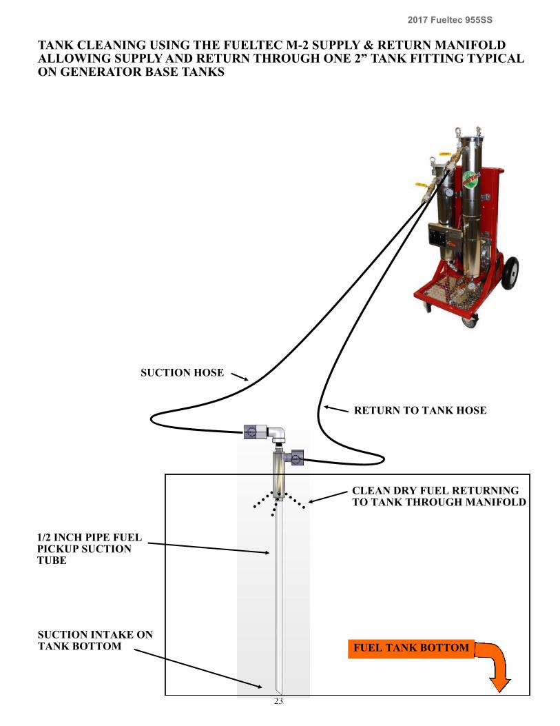
TANK CLEANING USING THE FUELTEC M-2 SUPPLY & RETURN MANIFOLD ALLOWING SUPPLY AND RETURN THROUGH ONE 2” TANK FITTING TYPICAL ON GENERATOR BASE TANKS
FUEL TANK BOTTOM
SUCTION HOSE
RETURN TO TANK HOSE
CLEAN DRY FUEL RETURNING TO TANK THROUGH MANIFOLD
SUCTION INTAKE ON TANK BOTTOM
1/2 INCH PIPE FUEL PICKUP SUCTION TUBE
24
2017 Fueltec 955SS
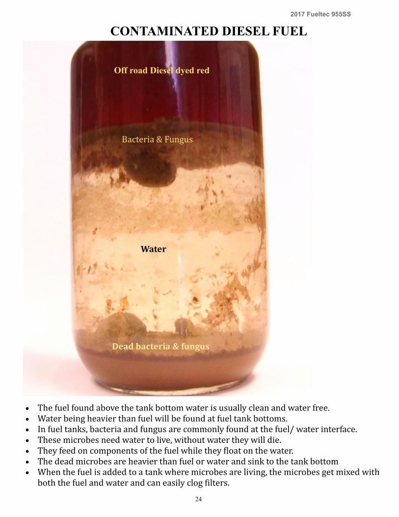
CONTAMINATED DIESEL FUEL
Off road Diesel dyed red
Bacteria & Fungus
Water
Dead bacteria & fungus
The fuel found above the tank bottom water is usually clean and water free. Water being heavier than fuel will be found at fuel tank bottoms. In fuel tanks, bacteria and fungus are commonly found at the fuel/ water interface. These microbes need water to live, without water they will die. They feed on components of the fuel while they float on the water. The dead microbes are heavier than fuel or water and sink to the tank bottom When the fuel is added to a tank where microbes are living, the microbes get mixed with
both the fuel and water and can easily clog filters.
25
2017 Fueltec 955SS
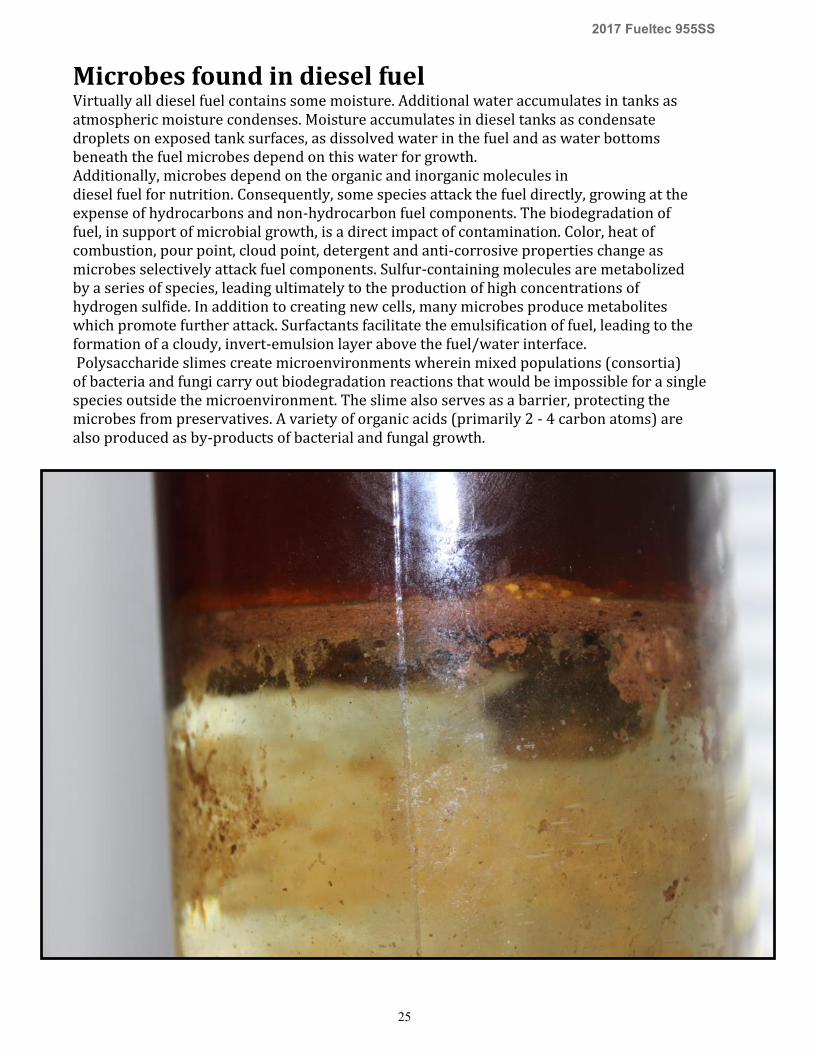
Microbes found in diesel fuel Virtually all diesel fuel contains some moisture. Additional water accumulates in tanks as atmospheric moisture condenses. Moisture accumulates in diesel tanks as condensate droplets on exposed tank surfaces, as dissolved water in the fuel and as water bottoms beneath the fuel microbes depend on this water for growth. Additionally, microbes depend on the organic and inorganic molecules in diesel fuel for nutrition. Consequently, some species attack the fuel directly, growing at the expense of hydrocarbons and non-hydrocarbon fuel components. The biodegradation of fuel, in support of microbial growth, is a direct impact of contamination. Color, heat of combustion, pour point, cloud point, detergent and anti-corrosive properties change as microbes selectively attack fuel components. Sulfur-containing molecules are metabolized by a series of species, leading ultimately to the production of high concentrations of hydrogen sulfide. In addition to creating new cells, many microbes produce metabolites which promote further attack. Surfactants facilitate the emulsification of fuel, leading to the formation of a cloudy, invert-emulsion layer above the fuel/water interface. Polysaccharide slimes create microenvironments wherein mixed populations (consortia) of bacteria and fungi carry out biodegradation reactions that would be impossible for a single species outside the microenvironment. The slime also serves as a barrier, protecting the microbes from preservatives. A variety of organic acids (primarily 2 - 4 carbon atoms) are also produced as by-products of bacterial and fungal growth.
Recommended


![Tank Cleaning Presentation · Title: Tank Cleaning Presentation [Compatibility Mode] Keywords ()](https://img.pdfslide.us/doc/110x75/5e7ee9464c9b0f56c8137b71/tank-cleaning-presentation-title-tank-cleaning-presentation-compatibility-mode.jpg)