a 16
035
Vine
yard
Blv
d. M
orga
n H
ill, C
A 9
5037
p
408
225
4314
f 408
225
207
9
e w
ww
.alls
enso
rs.c
om
all s
enso
rs
All Sensors DS-0274 Rev C
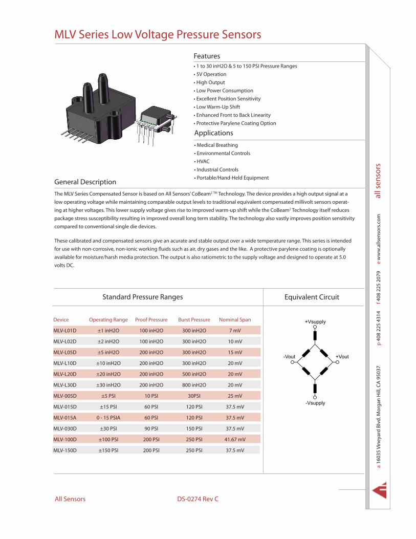
The MLV Series Compensated Sensor is based on All Sensors’ CoBeam2 TM Technology. The device provides a high output signal at a low operating voltage while maintaining comparable output levels to traditional equivalent compensated millivolt sensors operat-ing at higher voltages. This lower supply voltage gives rise to improved warm-up shift while the CoBeam2 Technology itself reduces package stress susceptibility resulting in improved overall long term stability. The technology also vastly improves position sensitivity compared to conventional single die devices.
These calibrated and compensated sensors give an acurate and stable output over a wide temperature range. This series is intended for use with non-corrosive, non-ionic working fluids such as air, dry gases and the like. A protective parylene coating is optionally available for moisture/harsh media protection. The output is also ratiometric to the supply voltage and designed to operate at 5.0 volts DC.
• 1 to 30 inH2O & 5 to 150 PSI Pressure Ranges • 5V Operation• High Output• Low Power Consumption• Excellent Position Sensitivity• Low Warm-Up Shift• Enhanced Front to Back Linearity• Protective Parylene Coating Option
• Medical Breathing• Environmental Controls• HVAC• Industrial Controls• Portable/Hand-Held Equipment
General Description
Applications
Features
MLV Series Low Voltage Pressure Sensors
Device Operating Range Proof Pressure Burst Pressure Nominal Span
MLV-L01D ±1 inH2O 100 inH2O 300 inH2O 7 mV
MLV-L02D ±2 inH2O 100 inH2O 300 inH2O 10 mV
MLV-L05D ±5 inH2O 200 inH2O 300 inH2O 15 mV
MLV-L10D ±10 inH2O 200 inH2O 300 inH2O 20 mV
MLV-L20D ±20 inH2O 200 inH2O 500 inH2O 20 mV
MLV-L30D ±30 inH2O 200 inH2O 800 inH2O 20 mV
MLV-005D ±5 PSI 10 PSI 30PSI 25 mV
MLV-015D ±15 PSI 60 PSI 120 PSI 37.5 mV
MLV-015A 0 - 15 PSIA 60 PSI 120 PSI 37.5 mV
MLV-030D ±30 PSI 90 PSI 150 PSI 37.5 mV
MLV-100D ±100 PSI 200 PSI 250 PSI 41.67 mV
MLV-150D ±150 PSI 200 PSI 250 PSI 37.5 mV
Standard Pressure Ranges Equivalent Circuit
+Vout-Vout
+Vsupply
-Vsupply
MLV Series Low Voltage Pressure Sensors
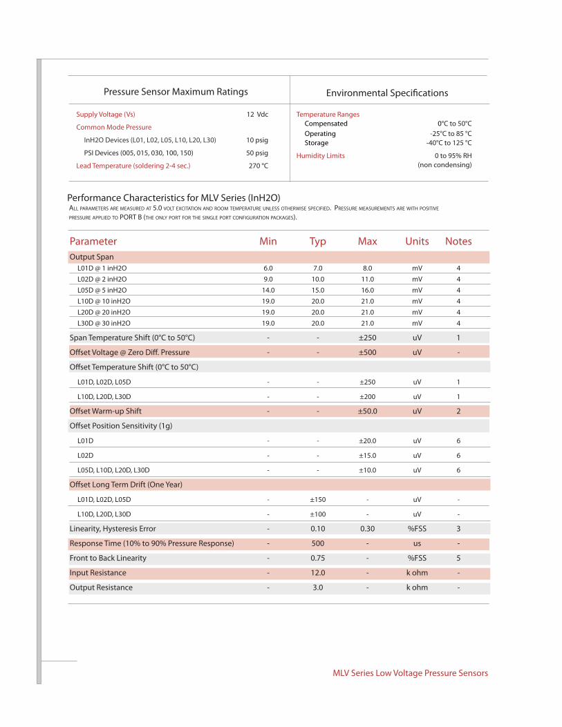
Parameter Min Typ Max Units NotesOutput Span L01D @ 1 inH2O 6.0 7.0 8.0 mV 4 L02D @ 2 inH2O 9.0 10.0 11.0 mV 4 L05D @ 5 inH2O 14.0 15.0 16.0 mV 4 L10D @ 10 inH2O 19.0 20.0 21.0 mV 4 L20D @ 20 inH2O 19.0 20.0 21.0 mV 4 L30D @ 30 inH2O 19.0 20.0 21.0 mV 4
Span Temperature Shift (0°C to 50°C) - - ±250 uV 1
Offset Voltage @ Zero Diff. Pressure - - ±500 uV -
Offset Temperature Shift (0°C to 50°C)
L01D, L02D, L05D - - ±250 uV 1
L10D, L20D, L30D - - ±200 uV 1
Offset Warm-up Shift - - ±50.0 uV 2
Offset Position Sensitivity (1g)
L01D - - ±20.0 uV 6
L02D - - ±15.0 uV 6
L05D, L10D, L20D, L30D - - ±10.0 uV 6
Offset Long Term Drift (One Year)
L01D, L02D, L05D - ±150 - uV -
L10D, L20D, L30D - ±100 - uV -
Linearity, Hysteresis Error - 0.10 0.30 %FSS 3
Response Time (10% to 90% Pressure Response) - 500 - us -
Front to Back Linearity - 0.75 - %FSS 5
Input Resistance - 12.0 - k ohm -
Output Resistance - 3.0 - k ohm -
Performance Characteristics for MLV Series (InH2O)All pArAmeters Are meAsured At 5.0 volt excitAtion And room temperAture unless otherwise specified. pressure meAsurements Are with positive pressure Applied to port B (the only port for the single port configurAtion pAckAges).
Pressure Sensor Maximum Ratings Environmental Specifications
Supply Voltage (Vs) 12 Vdc
Common Mode Pressure
InH2O Devices (L01, L02, L05, L10, L20, L30) 10 psig
PSI Devices (005, 015, 030, 100, 150) 50 psig
Lead Temperature (soldering 2-4 sec.) 270 °C
Temperature Ranges Compensated 0°C to 50°C Operating -25°C to 85 °C Storage -40°C to 125 °C
Humidity Limits 0 to 95% RH (non condensing)
a 16
035
Vine
yard
Blv
d. M
orga
n H
ill, C
A 9
5037
p
408
225
4314
f 408
225
207
9
e w
ww
.alls
enso
rs.c
om
all s
enso
rs
All Sensors DS-0274 Rev C
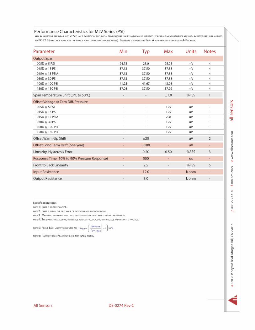
Parameter Min Typ Max Units NotesOutput Span 005D @ 5 PSI 24.75 25.0 25.25 mV 4 015D @ 15 PSI 37.13 37.50 37.88 mV 4 015A @ 15 PSIA 37.13 37.50 37.88 mV 4 030D @ 30 PSI 37.13 37.50 37.88 mV 4 100D @ 100 PSI 41.25 41.67 42.08 mV 4 150D @ 150 PSI 37.08 37.50 37.92 mV 4
Span Temperature Shift (0°C to 50°C) - - ±1.0 %FSS 1
Offset Voltage @ Zero Diff. Pressure 005D @ 5 PSI - - 125 uV - 015D @ 15 PSI - - 125 uV - 015A @ 15 PSIA - - 208 uV - 030D @ 30 PSI - - 125 uV - 100D @ 100 PSI - - 125 uV - 150D @ 150 PSI - - 125 uV -
Offset Warm-Up Shift - ±20 uV 2
Offset Long Term Drift (one year) - ±100 - uV -
Linearity, Hysteresis Error - 0.20 0.50 %FSS 3
Response Time (10% to 90% Pressure Response) - 500 - us -
Front to Back Linearity - 2.5 - %FSS 5
Input Resistance - 12.0 - k ohm -
Output Resistance - 3.0 - k ohm -
Performance Characteristics for MLV Series (PSI)All pArAmeters Are meAsured At 5.0 volt excitAtion And room temperAture unless otherwise specified. pressure meAsurements Are with positive pressure Applied to port B (the only port for the single port configurAtion pAckAges). pressure is Applied to port A for ABsolute devices in A-pAckAge.
Specification Notesnote 1: shift is relAtive to 25°c.note 2: shift is within the first hour of excitAtion Applied to the device.note 3: meAsured At one-hAlf full scAle rAted pressure using Best strAight line curve fit.note 4: the spAn is the AlgeBrAic difference Between full scAle output voltAge And the offset voltAge.
note 5: front-BAck linerity computed As: Lin FBSpan Front
Span Back1−
100⋅ %
note 6: pArAmeter is chArActerized And not 100% tested.
MLV Series Low Voltage Pressure Sensors
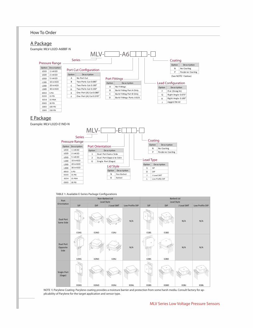
How To Order
TABLE 1: Available E-Series Package Configurations
NOTE 1) Parylene Coating: Parylene coating provides a moisture barrier and protection from some harsh media. Consult factory for ap-plicability of Parylene for the target application and sensor type.
(See NOTE 1 below)
E PackageExample: MLV-L02D-E1ND-N
Example: MLV-L02D-A6BBF-N
A Package
SIP DIP J Lead SMT SIP DIP J Lead SMT
Dual Port Same Side
E1NS E1ND E1NJ
N/A
E1BS E1BD
N/A N/A
Dual Port Opposite
Side
E2NS E2ND E2NJ
N/A
E2BS E2BD
N/A N/A
Single Port (Gage)
EGNS EGND EGNJ EGNL EGBS EGBD EGBJ EGBL
Lead StyleNon-Barbed Lid Barbed Lid
Port Lead Style
SeriesMLV- -A6 -
Port Fittings
Pressure RangeCoating
Op on De scrip on
A No Port Cut
B Two Ports Cut 0.085"
C Two Ports Cut 0.100"
D Two Ports Cut 0.150"
E One Port (A) Cut 0.080"
F One Port (A) Cut 0.370"
Op on De scrip on
A No Fi ngs
B Ba rb Fi ng Port A Only
C Ba rb Fi ng Port B Only
D Ba rb Fi ngs Ports A & B
Op on De scrip on
F Fl at (Straig ht)
Q Ri ght Angl e 0.075"
R Rig ht Angle 0.100"
J Jogge d Be nd
Op on De scrip on
N No Coa ng
P Paryle ne Coa ngL01D 1 i nH2O
L02D 2 i nH2O
L05D 5 i nH2O
L10D 10 in H2O
L20D 20 in H2O
L30D 30 in H2O
005 D 5 PSI015 D 15 PSI
015 A 15 PSIA
030 D 30 PSI
100 D 100 PSI
150 D 150 PSI
MLV- -E -
Op on De scrip on
N No Coa ng
P Paryle ne Coa ng
SeriesPressure Range Coating
Port Orientation
Lid Style
Lead Type
Op on De scrip on
1 Dual Port Sam e Si de
2 Dual Port Oppo si te Sid e
G Si ngle Port (Gag e)
Op on De scrip on
NN on-Barbe d
BB arbe d
Op on De scrip on
SS IP
DD IP
JJ -Lea d SMT
LL ow Pro le DIP
L01D 1 i nH2O
L02D 2 i nH2O
L05D 5 i nH2O
L10D 10 in H2O
L20D 20 in H2O
L30D 30 in H2O
005D 5 PSI015D 15 PSI
015A 15 PSIA
030D 30 PSI
SIP
DIP
J-Lead SMT
Low Profile DIP
Non-Barbed
Barbed
a 16
035
Vine
yard
Blv
d. M
orga
n H
ill, C
A 9
5037
p
408
225
4314
f 408
225
207
9
e w
ww
.alls
enso
rs.c
om
all s
enso
rs
All Sensors DS-0274 Rev C
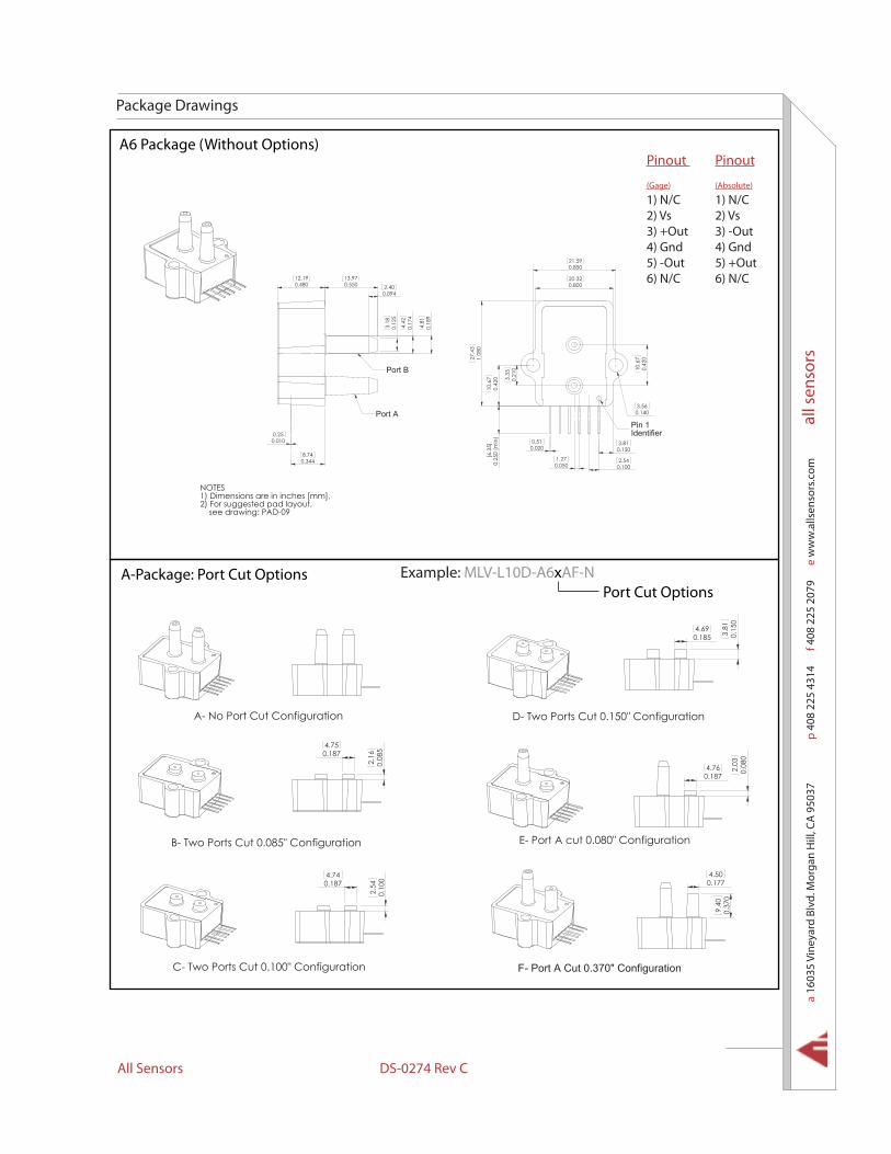
Package Drawings
NOTES1) Dimensions are in inches [mm].2) For suggested pad layout, see drawing: PAD-09
21.59
0.100
0.850
0.510.020
0.42
0
3.81
27.4
3
20.32
1.08
0
10.6
7
3.56
0.800
0.140
0.42
010
.67
2.54
0.150
0.25
0 (m
in)
[6.3
5]
0.21
05.
33
0.0501.27
Pin 1Identifier
0.17
4
0.550
0.12
5
12.192.40
4.81
3.18
0.480
0.25
4.42
13.97
0.18
9
0.010
0.094
0.3448.74
Port B
Port A
A6 Package (Without Options)
0.1854.69
0.15
03.
81A- No Port Cut Configuration D- Two Ports Cut 0.150" Configuration
4.500.177
0.37
09.
40
F- Port A Cut 0.370" Configuration
0.1874.74
0.10
02.
54
C- Two Ports Cut 0.100" Configuration
0.1874.75
0.08
52.
16
E- Port A cut 0.080" Configuration
4.760.187
0.08
02.
03
B- Two Ports Cut 0.085" Configuration
Example: MLV-L10D-A6xAF-NPort Cut Options
A-Package: Port Cut Options
Pinout
(Gage)
1) N/C2) Vs3) +Out4) Gnd5) -Out6) N/C
Pinout
(Absolute)
1) N/C2) Vs3) -Out4) Gnd5) +Out6) N/C
MLV Series Low Voltage Pressure Sensors
0.250 (min)[6.35]
0.100[2.60]
0.25
0.01
0
0.13
63.
45
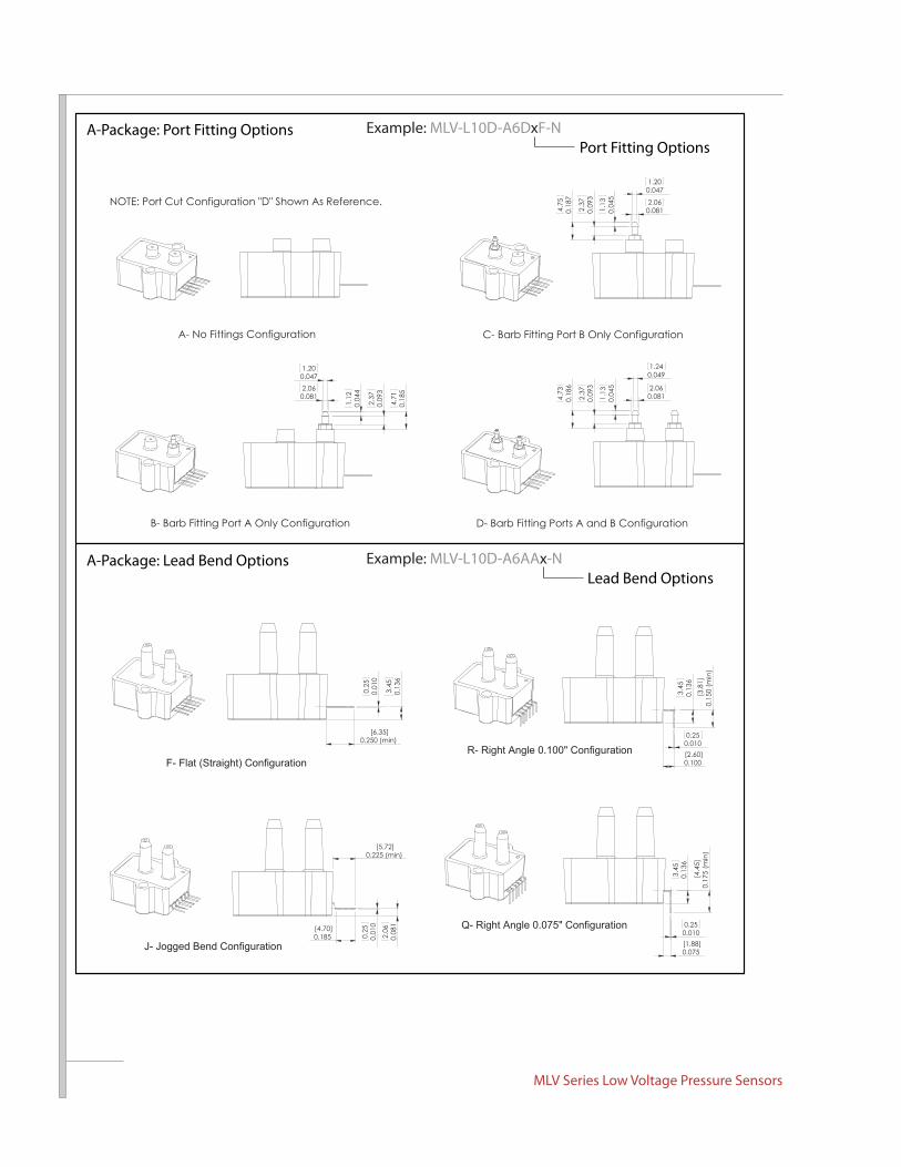
F- Flat (Straight) Configuration
0.250.010
0.13
63.
45
0.15
0 (m
in)
[3.8
1]
R- Right Angle 0.100" Configuration
0.075[1.88]
[4.70]
0.01
00.
25
0.185 0.08
12.
06
0.225 (min)[5.72]
0.250.010
0.13
63.
45
0.17
5 (m
in)
[4.4
5]
Q- Right Angle 0.075" Configuration
J- Jogged Bend Configuration
D- Barb Fitting Ports A and B ConfigurationB- Barb Fitting Port A Only Configuration
2.37
1.200.047
0.0812.06
1.12
0.04
4
0.09
3
0.18
54.
71 2.37
1.240.049
0.0812.06
1.13
0.04
5
0.09
3
0.18
64.
73
NOTE: Port Cut Configuration "D" Shown As Reference.
C- Barb Fitting Port B Only ConfigurationA- No Fittings Configuration
2.37
1.200.047
0.0812.06
1.13
0.04
5
0.09
3
0.18
74.
75
Example: MLV-L10D-A6DxF-NPort Fitting Options
A-Package: Port Fitting Options
Example: MLV-L10D-A6AAx-NLead Bend Options
A-Package: Lead Bend Options

a 16
035
Vine
yard
Blv
d. M
orga
n H
ill, C
A 9
5037
p
408
225
4314
f 408
225
207
9
e w
ww
.alls
enso
rs.c
om
all s
enso
rs
All Sensors DS-0274 Rev C
E1NS Package
0.640.025
0.2827.17
6.45
0.25
49.80
0.38
6
0.0100.25
0.1924.88
0.38
0 (n
om)
12.700.500
0.42510.79
[9.6
5]
2.04
0.51
0.42
510
.79
0.62
015
.75
0.10
7
0.082
2.73
0.020
2.10
0.08
0
0.1002.54
Port A
Port B
Pin 1 2 3 4
NOTES1)Dimensions are in inches [mm]2)For suggested pad layout, see drawing: PAD-01
E1BS Package
4.880.192
9.80
6.45
0.25
4
0.640.025
0.38
6
0.0100.25
0.3609.15
Port B
Port A
0.51
0.38
0 (n
om)
[9.6
5]
2.540.020
0.08
8
1.68
0.100
10.8
00.
425
10.80
2.11
2.24
2.73
0.425
0.10
7
12.700.500
0.083
15.7
50.
620
0.06
6
0.0451.14
Pin 1 2 3 4
2)For suggested pad layout, see drawing: PAD-01
NOTES1)Dimensions are in inches [mm]
Pinout1) Gnd2) +Out3) Vs4) -Out
Pinout1) Gnd2) +Out3) Vs4) -Out

MLV Series Low Voltage Pressure Sensors
E2NS Package
2.12
7.170.2820.64
0.025
0.250.010
0.084
0.38
69.
80
Pin 1 2 3 4
2.73
[9.6
5]0.
380
(nom
)
0.0822.10
15.7
5
0.42510.79
0.50012.70
0.020
0.42
510
.79
0.10
7
2.04
0.51
0.62
0
0.08
0
0.1002.54
Port BPort A
NOTES1)Dimensions are in inches [mm]2)For suggested pad layout, see drawing: PAD-01
E2BS Package
Pin 1 2 3 4
Port BPort A
0.50012.70
0.62
015
.75
0.08
82.
24
10.800.425
0.51 2.54
2.73
0.42
510
.80
0.10
7
0.020
0.38
0 (n
om)
[9.6
5]
2.110.083
1.68
0.06
6
0.100
0.0451.14
0.3609.15
0.25
0.640.025
9.80
0.38
6
0.010
0.0842.12
2)For suggested pad layout, see drawing: PAD-01
NOTES1)Dimensions are in inches [mm]
Pinout1) Gnd2) +Out3) Vs4) -Out
Pinout1) Gnd2) +Out3) Vs4) -Out
a 16
035
Vine
yard
Blv
d. M
orga
n H
ill, C
A 9
5037
p
408
225
4314
f 408
225
207
9
e w
ww
.alls
enso
rs.c
om
all s
enso
rs
All Sensors DS-0274 Rev C
Pinout1) Gnd2) +Out3) Vs4) -Out
Pinout1) Gnd2) +Out3) Vs4) -Out
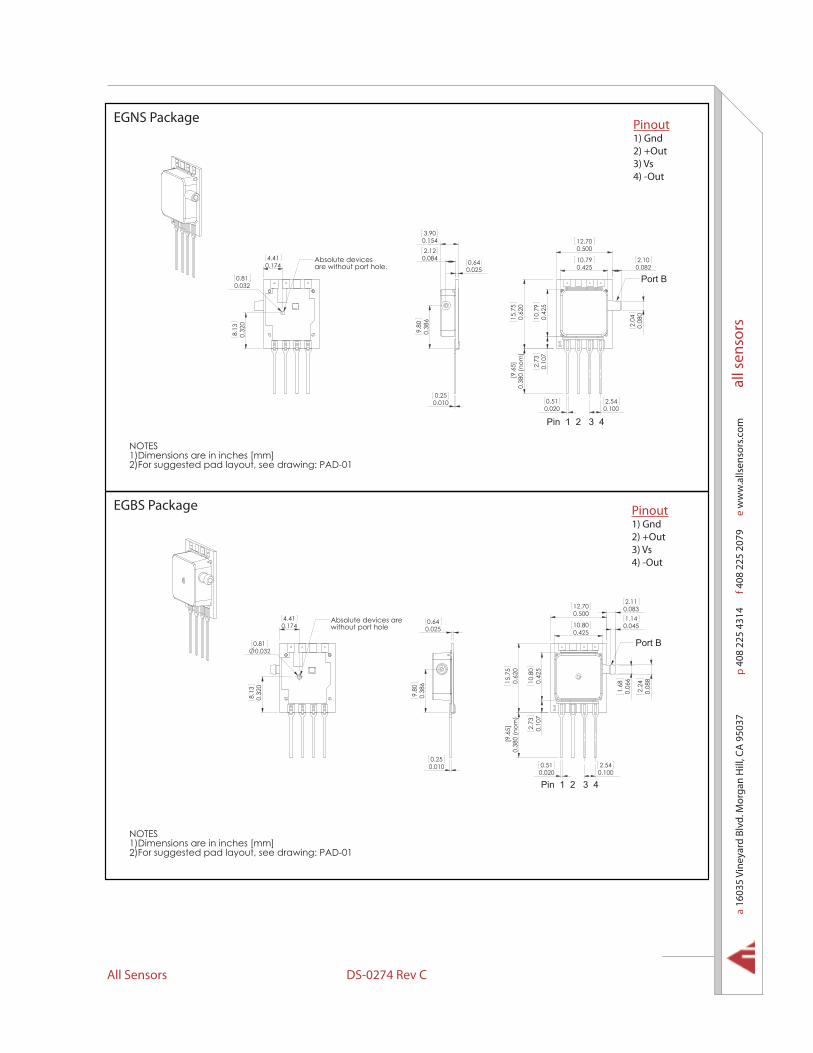
EGNS Package
0.25
2.12
0.64
0.38
69.
80
0.084
0.025
0.010
0.1543.90
Absolute devicesare without port hole.
4.41
8.13
0.32
0
0.174
0.0320.81 Port B
0.42
510
.79
0.62
015
.75
0.10
7
0.38
0 (n
om)
[9.6
5]
0.51
2.10
2.73
0.082
0.020
10.790.425
2.04
12.700.500
0.08
0
0.1002.54
Pin 1 2 3 4
NOTES1)Dimensions are in inches [mm]2)For suggested pad layout, see drawing: PAD-01
EGBS Package
0.0250.64
0.0100.25
0.38
69.
80
Pin 1 2 3 4
Port B
0.0832.11
0.50012.70
0.06
60.62
015
.75
2.24
0.100
0.38
0 (n
om)
[9.6
5] 2.73
0.51
1.680.
425
10.8
0
0.08
8
2.54
0.42510.80
0.10
7
0.020
0.0451.14Absolute devices are
without port hole0.1744.41
0.32
08.
13
0.0320.81
2)For suggested pad layout, see drawing: PAD-01
NOTES1)Dimensions are in inches [mm]

MLV Series Low Voltage Pressure Sensors
Pinout1) Gnd2) +Out3) Vs4) -Out5) Do Not Connect6) Do Not Connect7) Do Not Connect8) Do Not Connect
Pinout1) Gnd2) +Out3) Vs4) -Out5) Do Not Connect6) Do Not Connect7) Do Not Connect8) Do Not Connect
E1ND Package
0.2255.72
0.01
80.
46
Pin 1 2 3 4
Port B
Port A
Pin 8 7 6 5
0.10
7
0.08
0
2.1010.790.425
0.500
2.73
12.70
10.7
9
15.7
5
0.42
5
2.040.
620
0.082
0.1002.54
0.64 0.1924.88
0.05
8
0.25
0.63
0
7.170.282
0.0259.
800.
386 16
1.48
6.45
0.25
4
0.01
0
0.350(min)
8.89
NOTES1) Dimensions are in inches [mm]2) For suggested pad layout, see drawing: PAD-03
E1BD Package
1.48
0.38
69.
80
0.63
00.
2516
8.89
(min)
0.25
46.
45
0.025
4.880.1920.64
0.05
8
0.01
0
0.350
0.3609.15
0.2255.72
0.01
80.
46
Pin 1 2 3 4
Port B
Port A
Pin 8 7 6 5
1.680.
620
10.8
0
0.425
1.140.500
15.7
5
0.06
6
2.73
0.045
2.11
10.80
0.42
5
2.54
12.70 0.083
0.10
7
0.100
0.08
82.
24
NOTES1) Dimensions are in inches [mm]2) For suggested pad layout, see drawing: PAD-03
a 16
035
Vine
yard
Blv
d. M
orga
n H
ill, C
A 9
5037
p
408
225
4314
f 408
225
207
9
e w
ww
.alls
enso
rs.c
om
all s
enso
rs
All Sensors DS-0274 Rev C
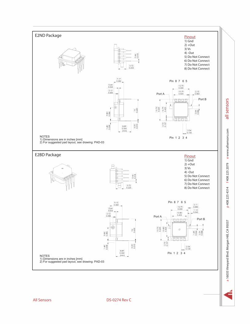
E2ND Package
0.25
0.63
0
7.170.282
0.64
2.120.084
0.025
9.80
0.38
61.
480.
058
160.
010
0.350(min)
8.89
0.2255.72
0.01
80.
46Pin 1 2 3 4
Pin 8 7 6 5
Port B
Port A2.1010.79
0.425
12.700.500
10.7
90.
425
0.62
015
.75
0.10
72.
73
2.04
0.08
0
0.082
0.1002.54
NOTES1) Dimensions are in inches [mm]2) For suggested pad layout, see drawing: PAD-03
E2BD Package
Port B
Pin 1 2 3 4
Port A
Pin 8 7 6 50.083
0.62
0
0.42
510
.80
0.10
7
0.100
0.045
1.68
2.73
2.11
0.425
1.140.50012.70
2.54
15.7
5
0.06
6
10.80
0.08
82.
24
8.89
0.64
0.05
8
16
(min)
0.63
00.
25
0.360
0.350
9.80
1.48
9.15
0.025
0.38
6
0.01
0
0.0842.12
0.2255.72
0.01
80.
46
NOTES1) Dimensions are in inches [mm]2) For suggested pad layout, see drawing: PAD-03
Pinout1) Gnd2) +Out3) Vs4) -Out5) Do Not Connect6) Do Not Connect7) Do Not Connect8) Do Not Connect
Pinout1) Gnd2) +Out3) Vs4) -Out5) Do Not Connect6) Do Not Connect7) Do Not Connect8) Do Not Connect

MLV Series Low Voltage Pressure Sensors
EGND Package
0.25
0.01
00.
630
16
0.64
2.120.084
0.025
9.80
0.38
61.
48
0.154
0.05
8
3.90
0.350(min)
8.89
Absolute devicesare without port hole.
4.41
8.13
0.32
0
0.174
0.0320.81
0.01
80.
46
0.2255.72
NOTES1) Dimensions are in inches [mm]
30-DAP :gniward ees ,tuoyal dap detseggus roF )24 3 2 1 niP
Pin 8 7 6 5
Port B
2.1010.790.425
12.700.500
10.7
90.
425
0.62
015
.75
0.10
72.
73
2.04
0.08
0
0.082
0.1002.54
EGBD Package
16
0.1694.28
0.642.12
0.0840.025
9.80
0.38
6 0.63
00.
250.
010
0.350(min)
8.89
Absolute devicesare without port hole.
4.41
8.13
0.32
0
0.174
0.0320.81
0.01
80.
46
0.2005.08
Pin 1 2 3 4
Pin 8 7 6 5
Port B
0.42510.80
12.700.500
0.62
0
0.083
15.7
5
2.54
0.42
5
0.100
10.8
00.
107
2.11
2.73
1.68
0.06
62.
240.
088
0.0451.14
NOTES1) Dimensions are in inches [mm]2) For suggested pad layout, see drawing: PAD-03
Pinout1) Gnd2) +Out3) Vs4) -Out5) Do Not Connect6) Do Not Connect7) Do Not Connect8) Do Not Connect
Pinout1) Gnd2) +Out3) Vs4) -Out5) Do Not Connect6) Do Not Connect7) Do Not Connect8) Do Not Connect

a 16
035
Vine
yard
Blv
d. M
orga
n H
ill, C
A 9
5037
p
408
225
4314
f 408
225
207
9
e w
ww
.alls
enso
rs.c
om
all s
enso
rs
All Sensors DS-0274 Rev C
E1NJ Package
A0.
254
6.45
7.170.282
9.80
0.38
6
0.0250.64 0.192
4.88
0.1553.94
DETAIL A SCALE 4 : 1
0.05
9
0.810.032R
1.51
0.0100.25
Pin 1 2 3 4
Pin 8 7 6 5
2.54
10.790.425
12.700.500
0.62
015
.75
10.7
90.
425
0.0822.10
2.73
2.04
0.08
0
0.100
0.10
7
0.0501.27
Port A
Port B
2)For suggested pad layout, see drawing: PAD-10
NOTES1)Dimensions are in inches [mm]
E2NJ Package
0.1553.94
DETAIL A SCALE 4 : 1
0.05
9
0.810.032R
1.51
0.0100.25
A
7.170.282
0.63
0
0.38
6
16
0.64
9.80
0.025
0.0842.12
Pin 1 2 3 4
Pin 8 7 6 5
Port B
Port A
0.50012.70
0.42
510
.79
0.62
015
.75
0.10
7
0.082
0.08
0
0.100
2.10
2.73
2.04
2.54
10.790.425
0.0501.27
NOTES1)Dimensions are in inches [mm]2)For suggested pad layout, see drawing: PAD-10
Pinout1) Gnd2) +Out3) Vs4) -Out5) Do Not Connect6) Do Not Connect7) Do Not Connect8) Do Not Connect
Pinout1) Gnd2) +Out3) Vs4) -Out5) Do Not Connect6) Do Not Connect7) Do Not Connect8) Do Not Connect
MLV Series Low Voltage Pressure Sensors
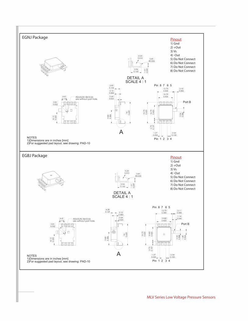
EGNJ Package
A
0.025
0.63
016
9.80
0.38
6
2.12
0.64
0.084
0.1543.90
Port B
2.54
0.42510.79
0.50012.70
0.42
510
.79
0.100
0.62
015
.75
0.10
7
2.04
0.082
0.08
0
2.73
2.10
0.0501.27
Pin 1 2 3 4
Pin 8 7 6 5
Absolute devicesare without port hole.
4.41
8.13
0.32
0
0.174
0.0320.81
0.1553.94
DETAIL A SCALE 4 : 1
0.05
9
R0.0320.81
1.51
0.0100.25
NOTES1)Dimensions are in inches [mm]2)For suggested pad layout, see drawing: PAD-10
EGBJ Package
Absolute devicesare without port hole.
4.41
8.13
0.32
0
0.174
0.0320.81
0.1553.94
DETAIL A SCALE 4 : 1
0.05
9
0.810.032R
1.51
0.0100.25
A
0.38
69.
80
0.025
0.63
016
2.12
0.640.084
0.1694.28
Pin 1 2 3 4
Pin 8 7 6 5
Port B
2.11
2.73
0.42
5
0.050
12.700.0830.500
15.7
5
0.06
6
0.045
2.54
1.6810
.80
1.27
0.62
0
1.14
0.100
0.425
0.10
7
10.80
0.08
82.
24
2)For suggested pad layout, see drawing: PAD-10
NOTES1)Dimensions are in inches [mm]
Pinout1) Gnd2) +Out3) Vs4) -Out5) Do Not Connect6) Do Not Connect7) Do Not Connect8) Do Not Connect
Pinout1) Gnd2) +Out3) Vs4) -Out5) Do Not Connect6) Do Not Connect7) Do Not Connect8) Do Not Connect
a 16
035
Vine
yard
Blv
d. M
orga
n H
ill, C
A 9
5037
p
408
225
4314
f 408
225
207
9
e w
ww
.alls
enso
rs.c
om
all s
enso
rs
All Sensors DS-0274 Rev C
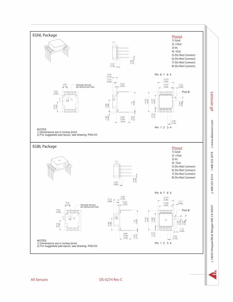
EGBL Package
16
0.1694.28
0.642.12
0.0840.025
9.80
0.38
6 0.63
00.
250.
010
0.350(min)
8.89
Absolute devicesare without port hole.
4.41
8.13
0.32
0
0.174
0.0320.81
Pin 1 2 3 4
Pin 8 7 6 5
Port B
0.42510.80
12.700.500
0.62
0
0.083
15.7
5
2.54
0.42
5
0.100
10.8
00.
107
2.11
2.73
1.68
0.06
62.
240.
088
0.0451.14
0.46
0.01
8
0.0802.03
NOTES1) Dimensions are in inches [mm]2) For suggested pad layout, see drawing: PAD-03
EGNL Package
0.25
0.01
00.
630
16
0.64
2.120.084
0.025
9.80
0.38
61.
48
0.154
0.05
8
3.90
0.350(min)
8.89
NOTES1) Dimensions are in inches [mm]
30-DAP :gniward ees ,tuoyal dap detseggus roF )2
Absolute devicesare without port hole.
4.41
8.13
0.32
0
0.174
0.0320.81
0.46
0.01
8
0.1052.67
4 3 2 1 niP
Pin 8 7 6 5
Port B
2.1010.790.425
12.700.500
10.7
90.
425
0.62
015
.75
0.10
72.
73
2.04
0.08
0
0.082
0.1002.54
Pinout1) Gnd2) +Out3) Vs4) -Out5) Do Not Connect6) Do Not Connect7) Do Not Connect8) Do Not Connect
Pinout1) Gnd2) +Out3) Vs4) -Out5) Do Not Connect6) Do Not Connect7) Do Not Connect8) Do Not Connect

MLV Series Low Voltage Pressure Sensors
All Sensors reserves the right to make changes to any products herein. All Sensors does not assume any liability arising out of the application or use of any product or circuit described herein, neither does it convey any license under its patent rights nor the rights of others.
Package Characteristics
Suggested Pad Layout
PAD-01
(Finished Size)0.035~0.039 inch
0.10
0(t
yp.)
2.54
PAD-03
(Finish Size)0.035~0.039 inch
0.63016
0.10
0(t
yp.)
2.54
(typ
.)0.
100
1.27
0.59014.99
2.54
0.05
0
0.0902.29
PAD-10
Approximate Port VolumePackage ID Port A Port B Units Notes Weight Units NotesA6AAx 132 33.6 mm3 1 9.3 Grams 2
A6BAx 119 20.3 mm3 1 8.7 Grams 2
A6CAx 119 20.5 mm3 1 8.8 Grams 2
A6DAx 120 21.3 mm3 1 8.8 Grams 2
A6EAx 119 33.6 mm3 1 8.9 Grams 2
A6FAx 125 33.6 mm3 1 9.2 Grams 2
E1Nx 174 168 mm3 - 1.2 Grams -
E2Nx 174 168 mm3 - 1.2 Grams -
EGNx 1.4 168 mm3 - 0.9 Grams -
Package NotesNote 1: Add 4.5 mm3 per port with barb fitting.Note 2: Add 0.15 gram per barb fitting.
Product Labeling
Lot Number
Part Number
Company
Example Device Label
All Sensors
R9J21-3A6AAF-N
MLV-L02D
* 5 PSI to 150 PSI devices may not be assembled with CoBeam2 TM Technology.
Recommended