MIPI technology and Tek test solution Oct. 25th 2011 Ryan Yu
Agenda
MIPI Standards Overview
MIPI PHY Testing (D-PHY and M-PHY)
MIPI CSI/DSI/DigRF
Summary, Q&A
2
3
Tektronix & MIPI Alliance
Tektronix is a Contributor Member of the MIPI Alliance– Tektronix participates in several MIPI Working Groups.
Tektronix Testing Support for MIPI includes; – Analog Validation– Protocol Debug and Verification
Tektronix is engaged on MIPI Test Methodologies working alongside the UNH-IOL.
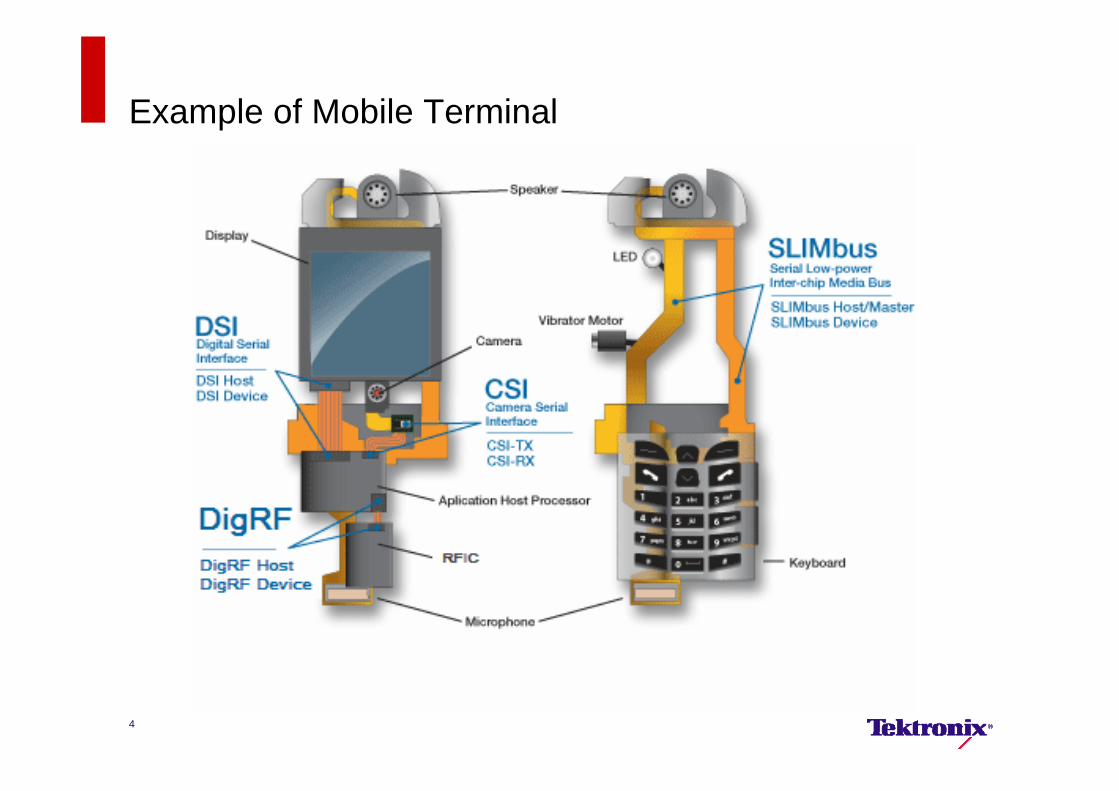
Example of Mobile Terminal
4
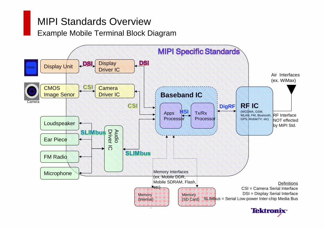
MIPI Standards Overview Example Mobile Terminal Block Diagram
Display Unit
CMOS Image Senor
RF IC(WCDMA, GSM, WLAN, FM, Bluetooth, GPS, MobileTV, etc)
Camera Driver IC
Display Driver IC
Loudspeaker
Ear Piece
Audio
Driver IC
FM Radio
Microphone
DigRFDigRF
Baseband IC
Tx/RxProcessor
Apps Processor
RF Interface NOT effected by MIPI Std.
Air Interfaces (ex. WiMax)
Memory(Internal)
Memory(SD Card)
Memory Interfaces(ex. Mobile DDR, Mobile SDRAM, Flash, etc)
HSIHSI
Display
Camera
DefinitionsCSI = Camera Serial InterfaceDSI = Display Serial Interface
SLIMbus = Serial Low-power Inter-chip Media Bus
5
What is MIPI DSI ?
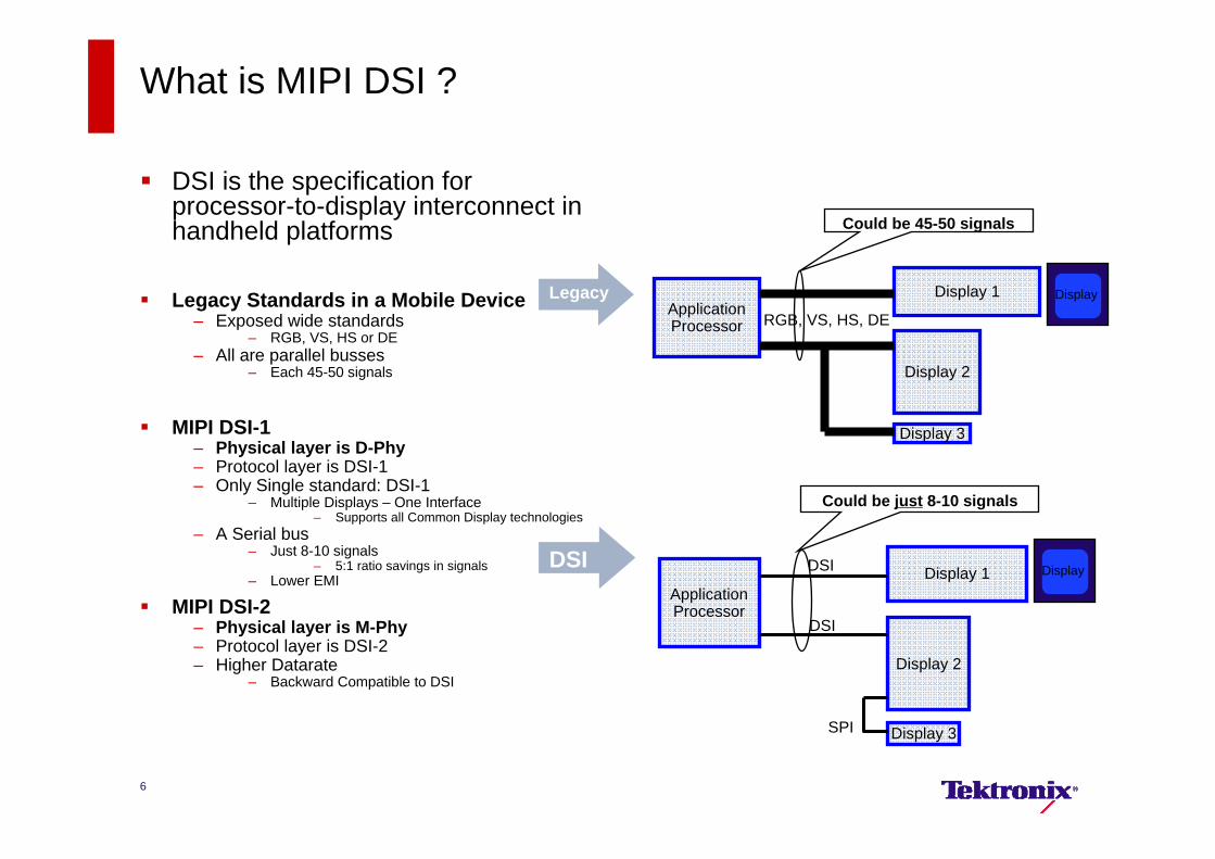
DSI is the specification for processor-to-display interconnect in handheld platforms
Legacy Standards in a Mobile Device– Exposed wide standards
– RGB, VS, HS or DE– All are parallel busses
– Each 45-50 signals
MIPI DSI-1– Physical layer is D-Phy– Protocol layer is DSI-1– Only Single standard: DSI-1
– Multiple Displays – One Interface– Supports all Common Display technologies
– A Serial bus– Just 8-10 signals
– 5:1 ratio savings in signals– Lower EMI
MIPI DSI-2– Physical layer is M-Phy– Protocol layer is DSI-2– Higher Datarate
– Backward Compatible to DSI
ApplicationProcessor
Display 1
Display 2
Display 3
RGB, VS, HS, DE
Could be 45-50 signals
ApplicationProcessor
Display 1
Display 2
Display 3
DSI
DSI
SPI
Could be just 8-10 signals
Display
Display
Legacy
DSI
6
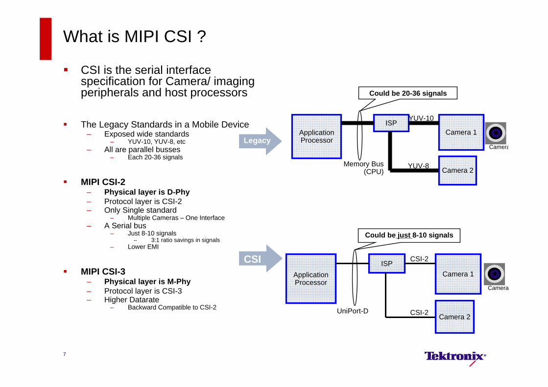
What is MIPI CSI ?
CSI is the serial interface specification for Camera/ imaging peripherals and host processors
The Legacy Standards in a Mobile Device– Exposed wide standards
– YUV-10, YUV-8, etc– All are parallel busses
– Each 20-36 signals
MIPI CSI-2– Physical layer is D-Phy– Protocol layer is CSI-2– Only Single standard
– Multiple Cameras – One Interface– A Serial bus
– Just 8-10 signals– 3:1 ratio savings in signals
– Lower EMI
MIPI CSI-3– Physical layer is M-Phy– Protocol layer is CSI-3– Higher Datarate
– Backward Compatible to CSI-2
ApplicationProcessor
Camera 1ISP
Memory Bus (CPU) Camera 2
YUV-10
YUV-8
Could be 20-36 signals
ApplicationProcessor
Camera 1ISP
UniPort-DCamera 2
CSI-2
CSI-2
Could be just 8-10 signals
Camera
Camera
7
Legacy
CSI
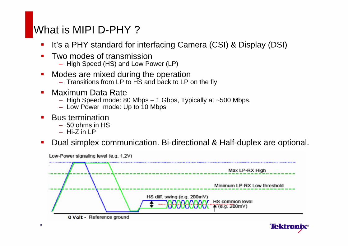
It’s a PHY standard for interfacing Camera (CSI) & Display (DSI) Two modes of transmission
– High Speed (HS) and Low Power (LP)
Modes are mixed during the operation– Transitions from LP to HS and back to LP on the fly
Maximum Data Rate– High Speed mode: 80 Mbps – 1 Gbps, Typically at ~500 Mbps.– Low Power mode: Up to 10 Mbps
Bus termination – 50 ohms in HS– Hi-Z in LP
Dual simplex communication. Bi-directional & Half-duplex are optional.
What is MIPI D-PHY ?
8
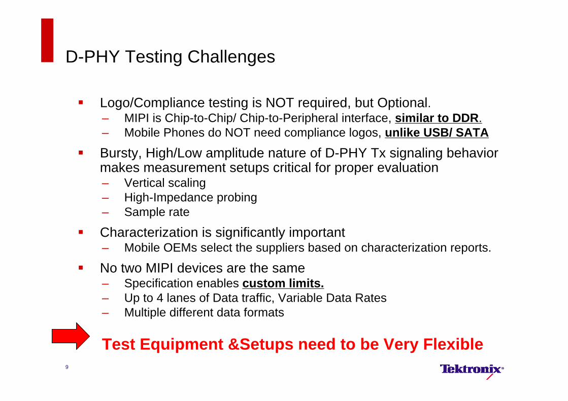
D-PHY Testing Challenges
Logo/Compliance testing is NOT required, but Optional.– MIPI is Chip-to-Chip/ Chip-to-Peripheral interface, similar to DDR.– Mobile Phones do NOT need compliance logos, unlike USB/ SATA
Bursty, High/Low amplitude nature of D-PHY Tx signaling behavior makes measurement setups critical for proper evaluation– Vertical scaling– High-Impedance probing– Sample rate
Characterization is significantly important – Mobile OEMs select the suppliers based on characterization reports.
No two MIPI devices are the same– Specification enables custom limits. – Up to 4 lanes of Data traffic, Variable Data Rates– Multiple different data formats
Test Equipment &Setups need to be Very Flexible9
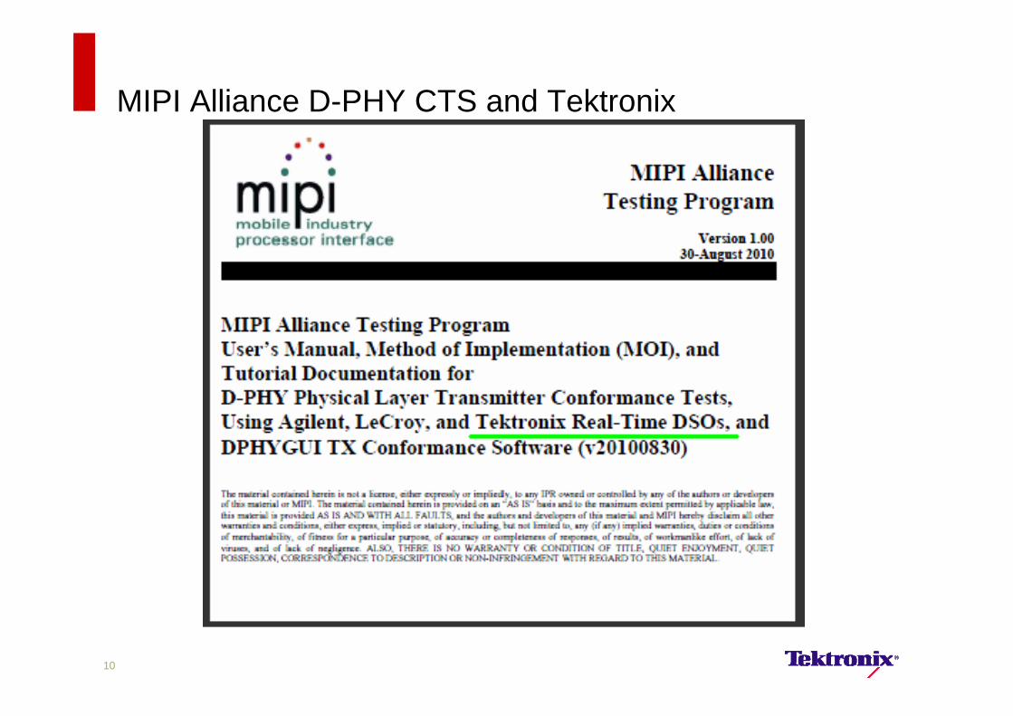
MIPI Alliance D-PHY CTS and Tektronix
10
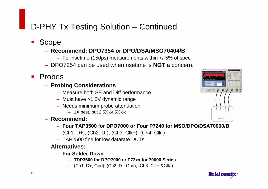
D-PHY Tx Testing Solution – Continued
Scope– Recommend: DPO7354 or DPO/DSA/MSO70404/B
– For risetime (150ps) measurements within +/-5% of spec– DPO7254 can be used when risetime is NOT a concern.
Probes– Probing Considerations
– Measure both SE and Diff performance– Must have >1.2V dynamic range– Needs minimum probe attenuation
– 1X best, but 2.5X or 5X ok– Recommend:
– Four TAP3500 for DPO7000 or Four P7240 for MSO/DPO/DSA70000/B– (Ch1: D+), (Ch2: D-), (Ch3: Clk+), (Ch4: Clk-)– TAP2500 fine for low datarate DUTs
– Alternatives: – For Solder-Down
– TDP3500 for DPO7000 or P73xx for 70000 Series– (Ch1: D+, Gnd), (Ch2: D-, Gnd), (Ch3: Clk+ &Clk-)
11
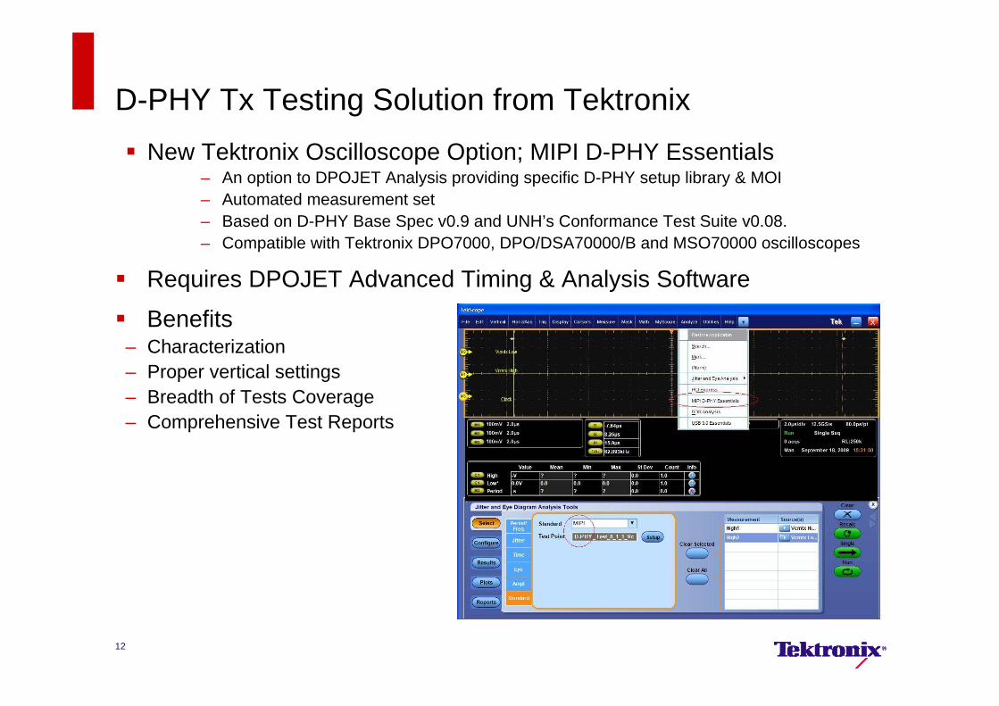
D-PHY Tx Testing Solution from Tektronix New Tektronix Oscilloscope Option; MIPI D-PHY Essentials
– An option to DPOJET Analysis providing specific D-PHY setup library & MOI– Automated measurement set– Based on D-PHY Base Spec v0.9 and UNH’s Conformance Test Suite v0.08.– Compatible with Tektronix DPO7000, DPO/DSA70000/B and MSO70000 oscilloscopes
Requires DPOJET Advanced Timing & Analysis Software
Benefits– Characterization– Proper vertical settings– Breadth of Tests Coverage– Comprehensive Test Reports
12
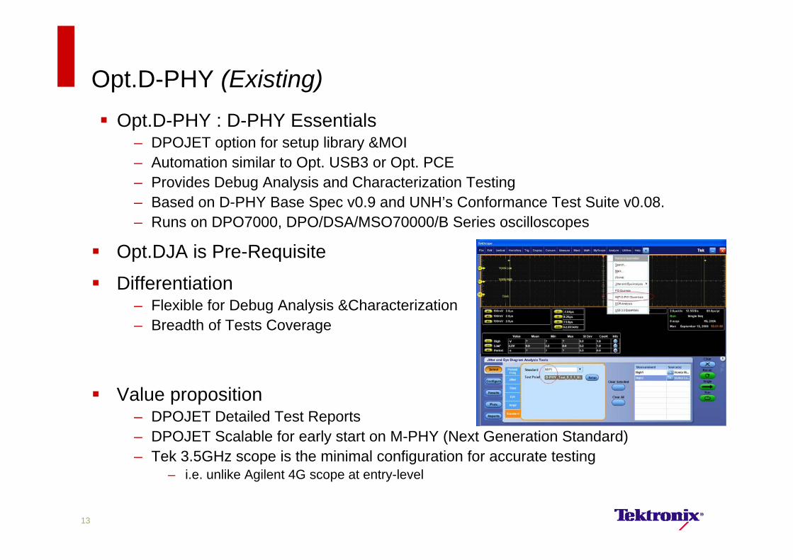
Opt.D-PHY (Existing) Opt.D-PHY : D-PHY Essentials
– DPOJET option for setup library &MOI– Automation similar to Opt. USB3 or Opt. PCE– Provides Debug Analysis and Characterization Testing– Based on D-PHY Base Spec v0.9 and UNH’s Conformance Test Suite v0.08.– Runs on DPO7000, DPO/DSA/MSO70000/B Series oscilloscopes
Opt.DJA is Pre-Requisite
Differentiation– Flexible for Debug Analysis &Characterization– Breadth of Tests Coverage
Value proposition– DPOJET Detailed Test Reports– DPOJET Scalable for early start on M-PHY (Next Generation Standard)– Tek 3.5GHz scope is the minimal configuration for accurate testing
– i.e. unlike Agilent 4G scope at entry-level
13
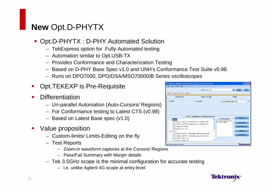
New Opt.D-PHYTX Opt.D-PHYTX : D-PHY Automated Solution
– TekExpress option for Fully-Automated testing– Automation similar to Opt.USB-TX– Provides Conformance and Characterization Testing– Based on D-PHY Base Spec v1.0 and UNH’s Conformance Test Suite v0.98.– Runs on DPO7000, DPO/DSA/MSO70000/B Series oscilloscopes
Opt.TEKEXP is Pre-Requisite
Differentiation– Un-parallel Automation (Auto-Cursors/ Regions)– For Conformance testing to Latest CTS (v0.98)– Based on Latest Base spec (v1.0)
Value proposition– Custom-limits/ Limits-Editing on the fly– Test Reports
– Zoom-in waveform captures at the Cursors/ Regions– Pass/Fail Summary with Margin details
– Tek 3.5GHz scope is the minimal configuration for accurate testing– i.e. unlike Agilent 4G scope at entry-level
14
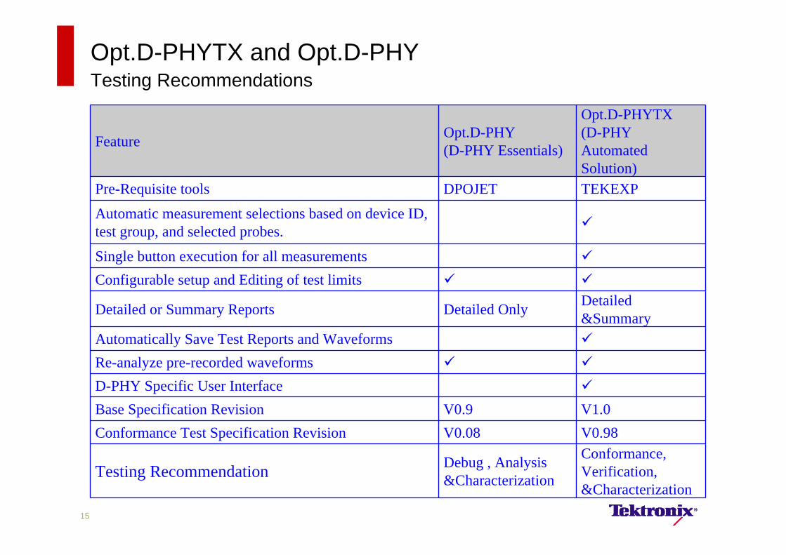
Opt.D-PHYTX and Opt.D-PHYTesting Recommendations
Feature Opt.D-PHY (D-PHY Essentials)
Opt.D-PHYTX (D-PHY Automated Solution)
Pre-Requisite tools DPOJET TEKEXP
Automatic measurement selections based on device ID, test group, and selected probes.
Single button execution for all measurements
Configurable setup and Editing of test limits
Detailed or Summary Reports Detailed Only Detailed &Summary
Automatically Save Test Reports and Waveforms
Re-analyze pre-recorded waveforms
D-PHY Specific User Interface
Base Specification Revision V0.9 V1.0Conformance Test Specification Revision V0.08 V0.98
Testing Recommendation Debug , Analysis &Characterization
Conformance, Verification, &Characterization
15
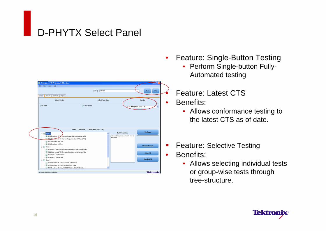
D-PHYTX Select Panel
• Feature: Single-Button Testing• Perform Single-button Fully-
Automated testing
• Feature: Latest CTS• Benefits:
• Allows conformance testing to the latest CTS as of date.
Feature: Selective Testing• Benefits:
• Allows selecting individual tests or group-wise tests through tree-structure.
16
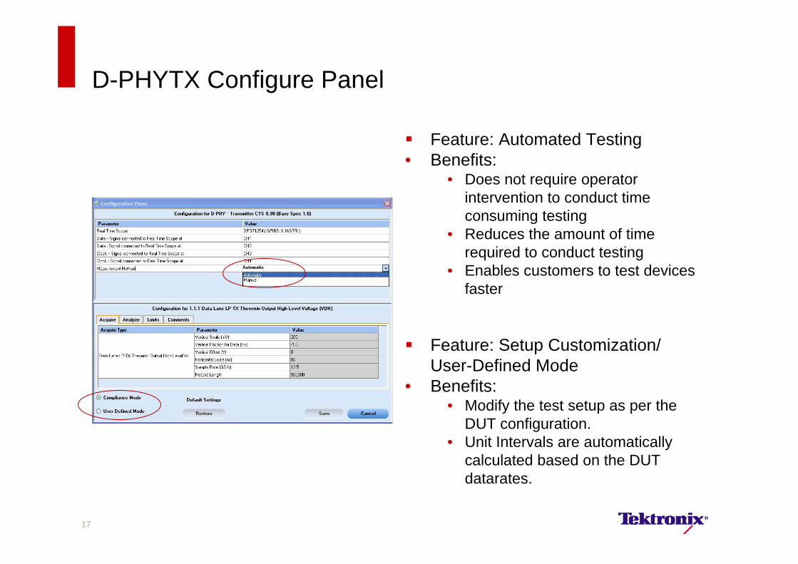
D-PHYTX Configure Panel
Feature: Automated Testing• Benefits:
• Does not require operator intervention to conduct time consuming testing
• Reduces the amount of time required to conduct testing
• Enables customers to test devices faster
Feature: Setup Customization/ User-Defined Mode
• Benefits:• Modify the test setup as per the
DUT configuration.• Unit Intervals are automatically
calculated based on the DUT datarates.
17
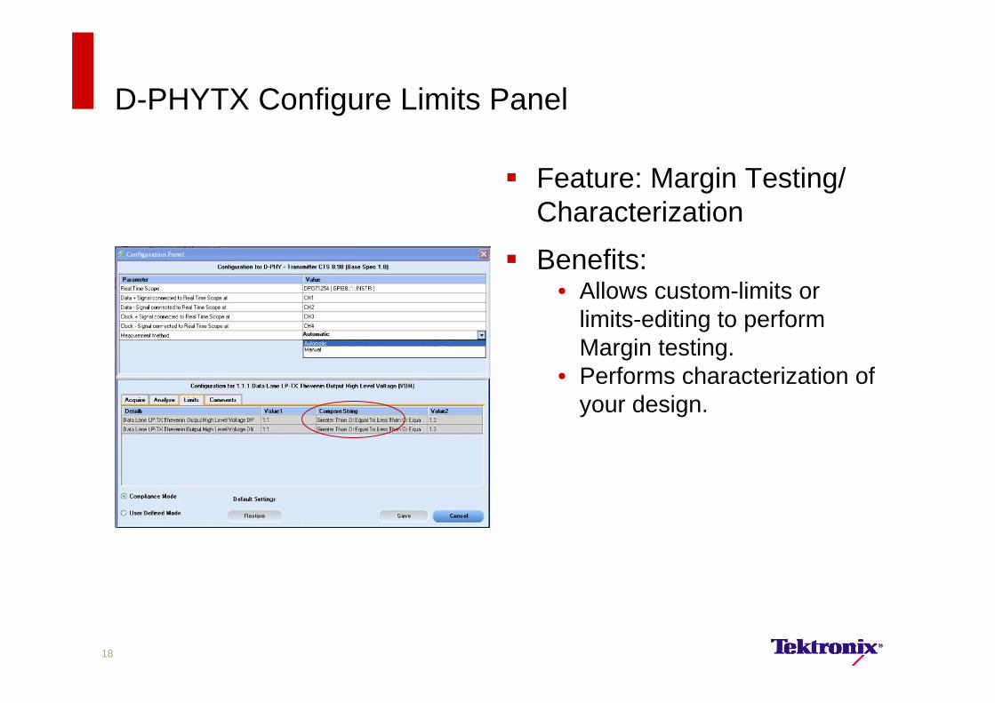
D-PHYTX Configure Limits Panel
Feature: Margin Testing/ Characterization
Benefits:• Allows custom-limits or
limits-editing to perform Margin testing.
• Performs characterization of your design.
18
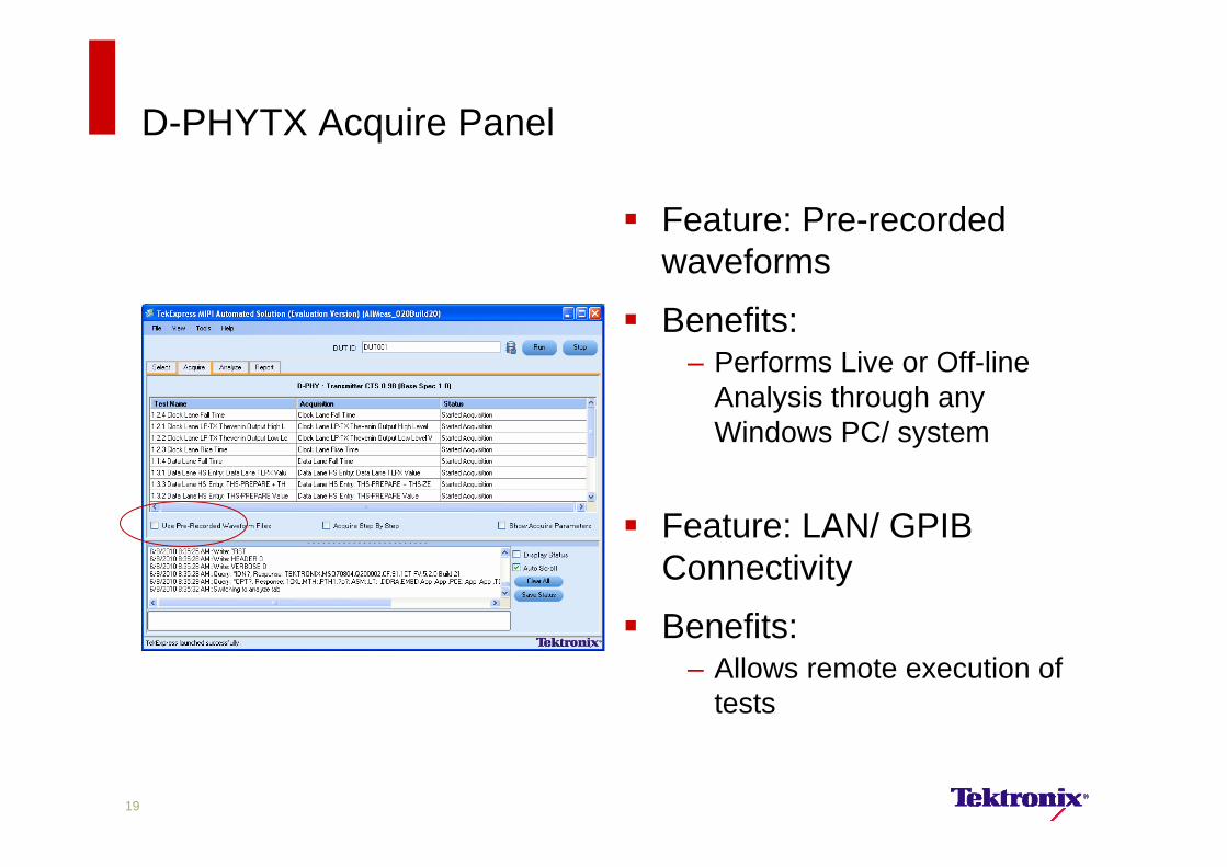
D-PHYTX Acquire Panel
Feature: Pre-recorded waveforms
Benefits:– Performs Live or Off-line
Analysis through any Windows PC/ system
Feature: LAN/ GPIB Connectivity
Benefits:– Allows remote execution of
tests
19
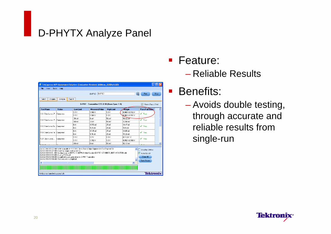
D-PHYTX Analyze Panel
Feature:– Reliable Results
Benefits:– Avoids double testing,
through accurate and reliable results from single-run
20
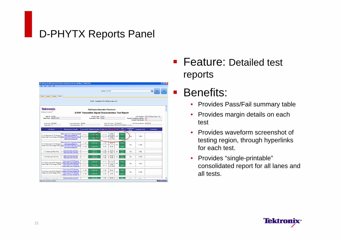
D-PHYTX Reports Panel
Feature: Detailed test reports
Benefits:• Provides Pass/Fail summary table• Provides margin details on each
test• Provides waveform screenshot of
testing region, through hyperlinks for each test.
• Provides “single-printable”consolidated report for all lanes and all tests.
21
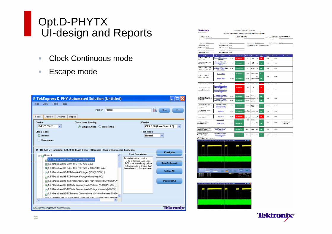
Opt.D-PHYTX UI-design and Reports
22
Clock Continuous mode
Escape mode
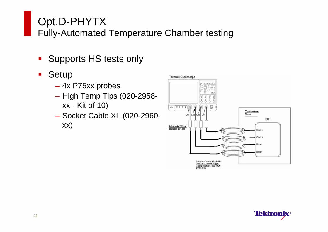
Opt.D-PHYTX Fully-Automated Temperature Chamber testing
Supports HS tests only
Setup– 4x P75xx probes– High Temp Tips (020-2958-
xx - Kit of 10)– Socket Cable XL (020-2960-
xx)
23
Opt.D-PHYTX Release2Error Handling
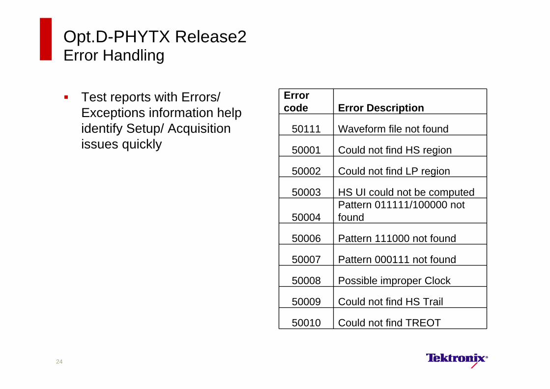
Test reports with Errors/ Exceptions information help identify Setup/ Acquisition issues quickly
Error code Error Description
50111 Waveform file not found
50001 Could not find HS region
50002 Could not find LP region
50003 HS UI could not be computed
50004Pattern 011111/100000 not found
50006 Pattern 111000 not found
50007 Pattern 000111 not found
50008 Possible improper Clock
50009 Could not find HS Trail
50010 Could not find TREOT
24
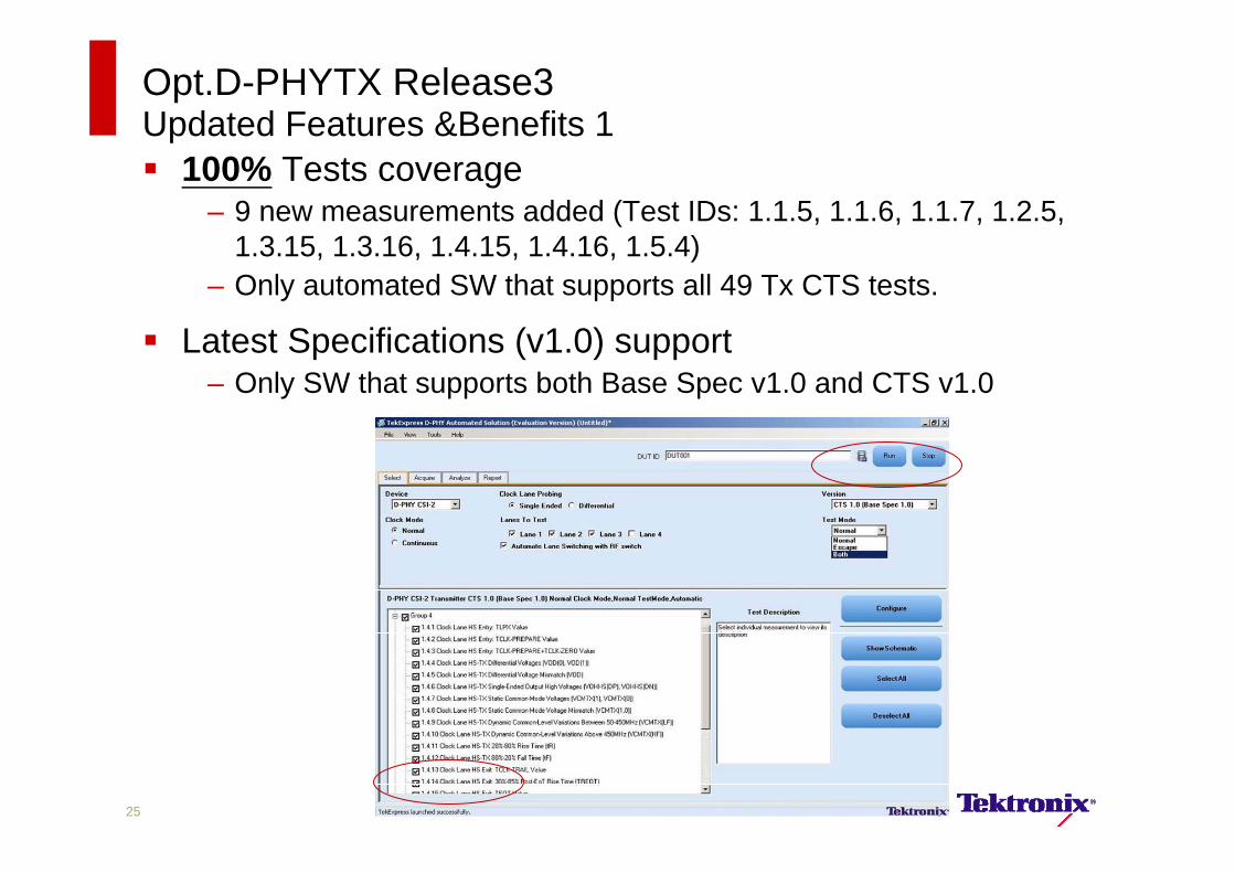
Opt.D-PHYTX Release3Updated Features &Benefits 1 100% Tests coverage
– 9 new measurements added (Test IDs: 1.1.5, 1.1.6, 1.1.7, 1.2.5, 1.3.15, 1.3.16, 1.4.15, 1.4.16, 1.5.4)
– Only automated SW that supports all 49 Tx CTS tests.
Latest Specifications (v1.0) support– Only SW that supports both Base Spec v1.0 and CTS v1.0
25
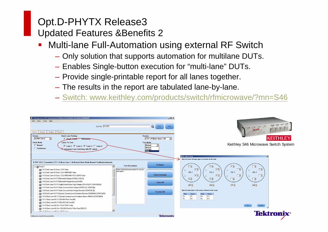
Opt.D-PHYTX Release3Updated Features &Benefits 2 Multi-lane Full-Automation using external RF Switch
– Only solution that supports automation for multilane DUTs. – Enables Single-button execution for “multi-lane” DUTs. – Provide single-printable report for all lanes together. – The results in the report are tabulated lane-by-lane.– Switch: www.keithley.com/products/switch/rfmicrowave/?mn=S46
26
Keithley S46 Microwave Switch System
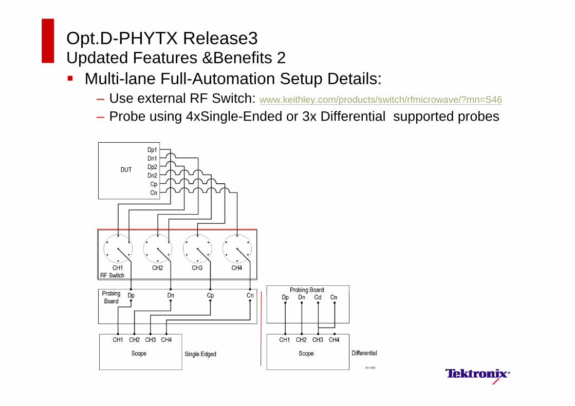
Opt.D-PHYTX Release3Updated Features &Benefits 2 Multi-lane Full-Automation Setup Details:
– Use external RF Switch: www.keithley.com/products/switch/rfmicrowave/?mn=S46
– Probe using 4xSingle-Ended or 3x Differential supported probes
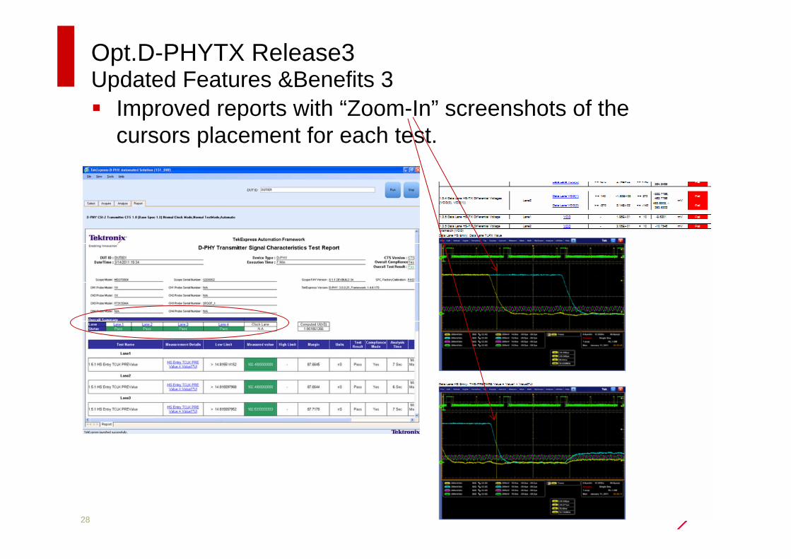
Opt.D-PHYTX Release3Updated Features &Benefits 3 Improved reports with “Zoom-In” screenshots of the
cursors placement for each test.
28
D-PHY Tx Testing Solution – Continued
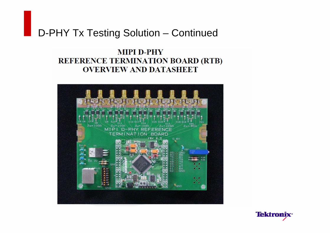
Fixtures– Issue with HS vs. LP termination, Z id load variation, C load– Ideally, fixture would provide active reference termination– Solder-in high impedance SE probes or DIFF probes connected for SE
are best for in-situ test– No standard fixture defined by MIPI– Tektronix Recommendation:
– Follow guidance and purchase as necessary from UNH-IOL– MIPI D-PHY Reference Termination Board $2,395.00– MIPI TLIS Board $795.00– MIPI D-PHY Probing Board $450.00– SMA Alignment Fixture $95.00– SMA Couplers $9.00– http://www.iol.unh.edu/services/testing/mipi/MIPI_Test_Fixture_Order_Form.
doc
Test Data Generation– Vendor specific– No standard test pattern generation defined
29
D-PHY Tx Testing Solution – Continued
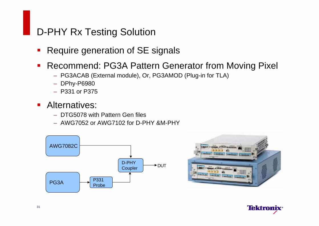
D-PHY Rx Testing Solution
Require generation of SE signals
Recommend: PG3A Pattern Generator from Moving Pixel– PG3ACAB (External module), Or, PG3AMOD (Plug-in for TLA)– DPhy-P6980– P331 or P375
Alternatives:– DTG5078 with Pattern Gen files– AWG7052 or AWG7102 for D-PHY &M-PHY
31
AWG7082C
PG3A
D-PHY Coupler DUT
P331Probe
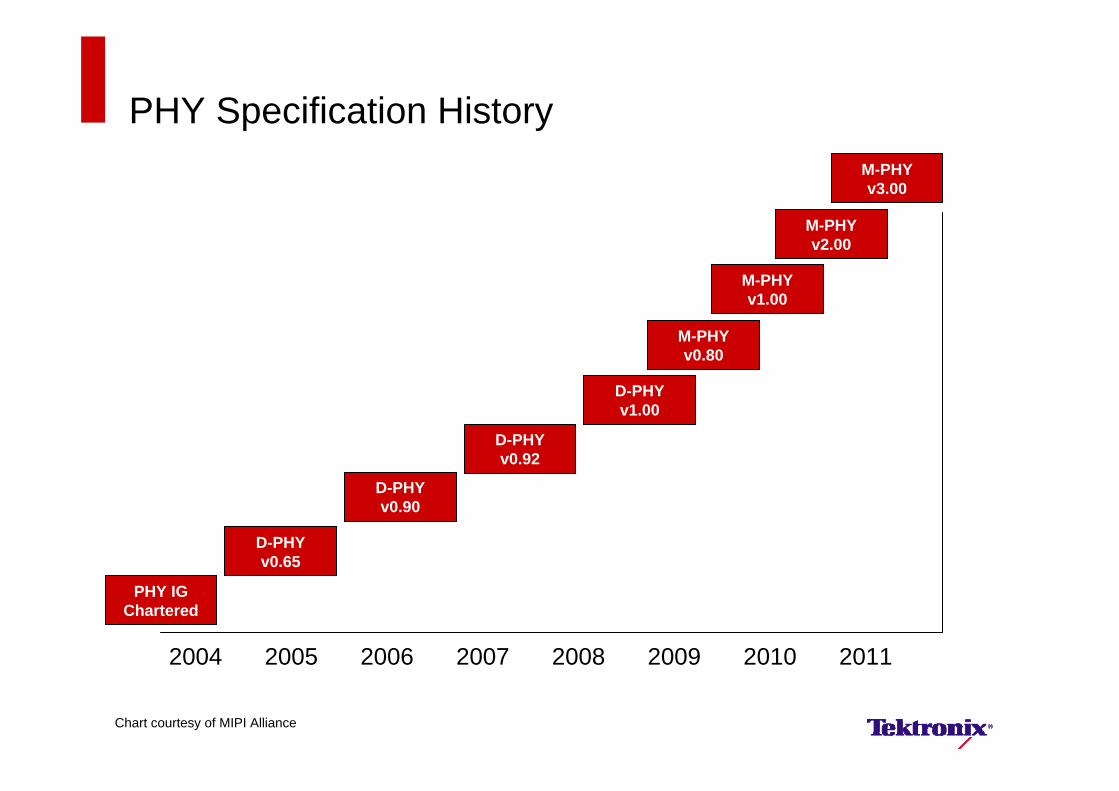
PHY Specification History
PHY IG Chartered
2004 2005 2006 2007 2008 2009 2010 2011
D-PHY v0.65
D-PHY v0.90
D-PHY v0.92
D-PHY v1.00
M-PHY v0.80
M-PHY v1.00
M-PHY v2.00
M-PHY v3.00
Chart courtesy of MIPI Alliance
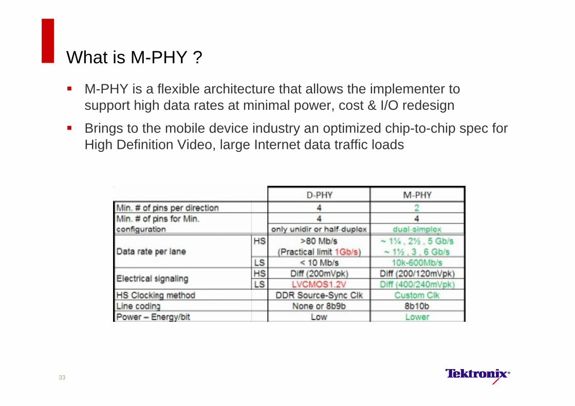
What is M-PHY ?
M-PHY is a flexible architecture that allows the implementer to support high data rates at minimal power, cost & I/O redesign
Brings to the mobile device industry an optimized chip-to-chip spec for High Definition Video, large Internet data traffic loads
33
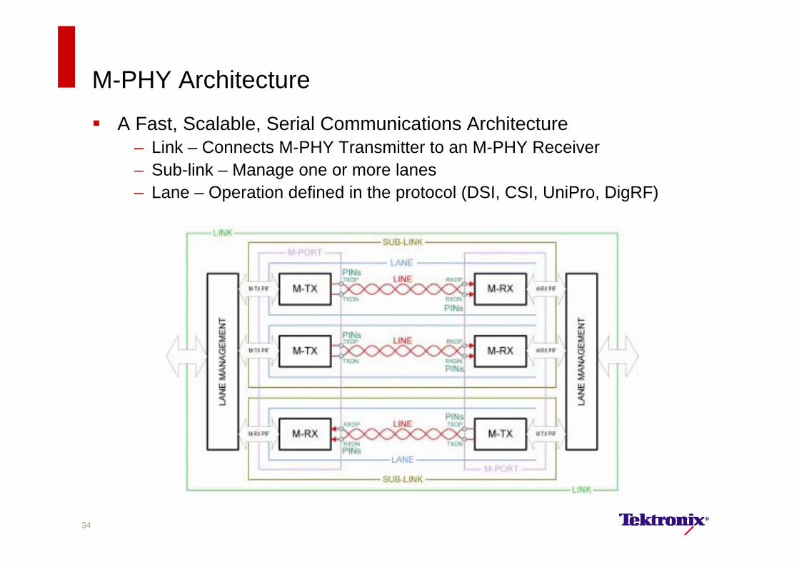
M-PHY Architecture
A Fast, Scalable, Serial Communications Architecture– Link – Connects M-PHY Transmitter to an M-PHY Receiver– Sub-link – Manage one or more lanes– Lane – Operation defined in the protocol (DSI, CSI, UniPro, DigRF)
34
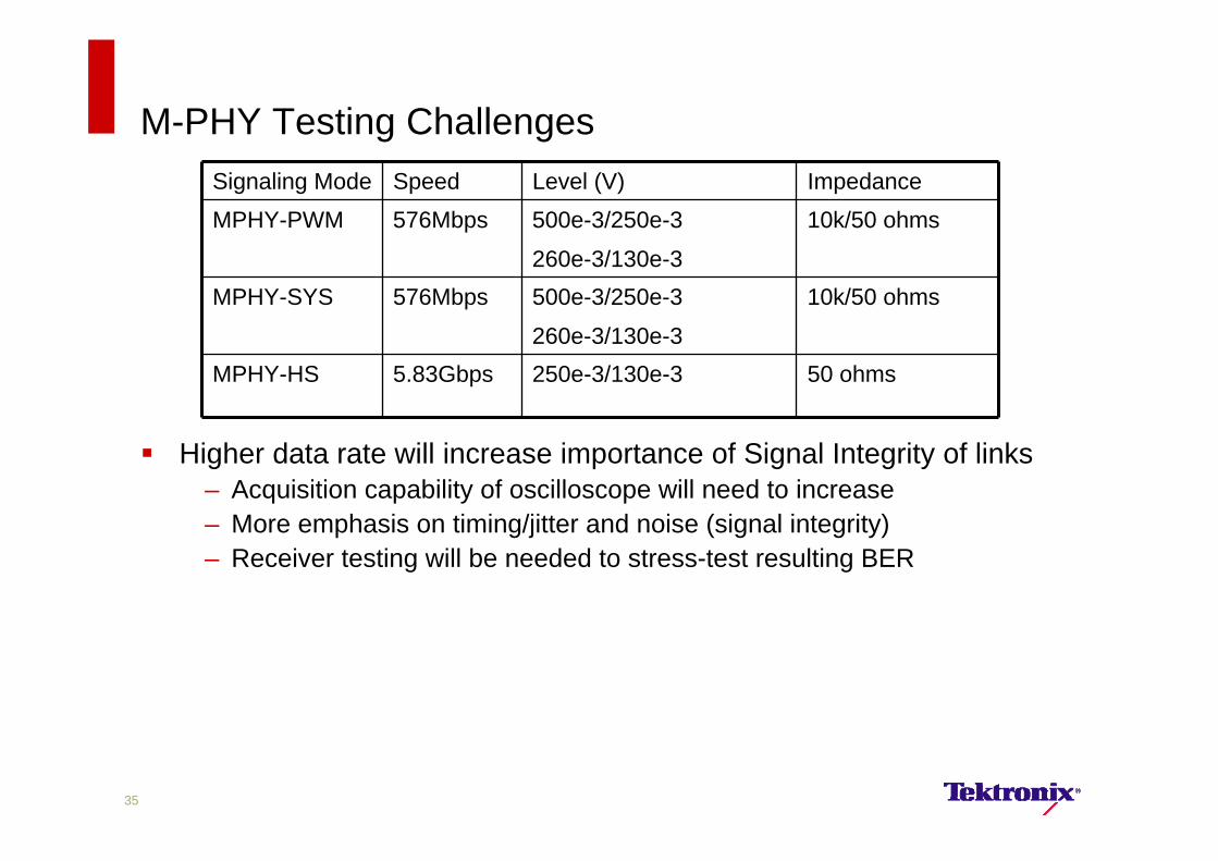
M-PHY Testing Challenges
Higher data rate will increase importance of Signal Integrity of links– Acquisition capability of oscilloscope will need to increase– More emphasis on timing/jitter and noise (signal integrity)– Receiver testing will be needed to stress-test resulting BER
Signaling Mode Speed Level (V) ImpedanceMPHY-PWM 576Mbps 500e-3/250e-3
260e-3/130e-3
10k/50 ohms
MPHY-SYS 576Mbps 500e-3/250e-3
260e-3/130e-3
10k/50 ohms
MPHY-HS 5.83Gbps 250e-3/130e-3 50 ohms
35
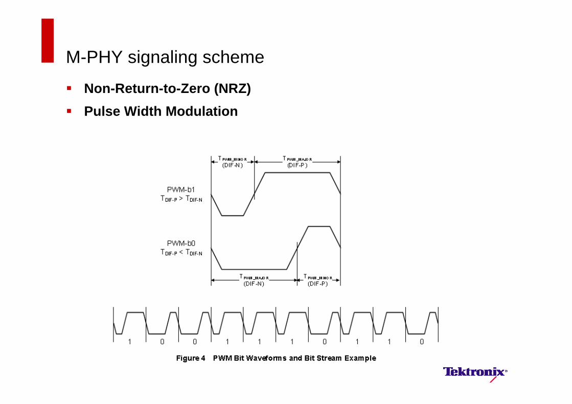
M-PHY signaling scheme
Non-Return-to-Zero (NRZ) Pulse Width Modulation
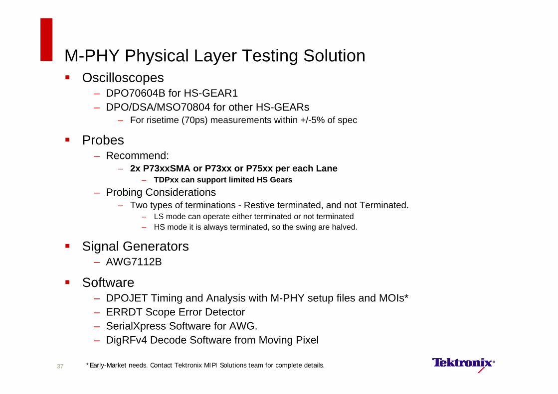
M-PHY Physical Layer Testing Solution Oscilloscopes
– DPO70604B for HS-GEAR1– DPO/DSA/MSO70804 for other HS-GEARs
– For risetime (70ps) measurements within +/-5% of spec
Probes– Recommend:
– 2x P73xxSMA or P73xx or P75xx per each Lane– TDPxx can support limited HS Gears
– Probing Considerations– Two types of terminations - Restive terminated, and not Terminated.
– LS mode can operate either terminated or not terminated– HS mode it is always terminated, so the swing are halved.
Signal Generators– AWG7112B
Software– DPOJET Timing and Analysis with M-PHY setup files and MOIs*– ERRDT Scope Error Detector– SerialXpress Software for AWG.– DigRFv4 Decode Software from Moving Pixel
37 *Early-Market needs. Contact Tektronix MIPI Solutions team for complete details.

M-PHY Physical Layer Testing Solution Oscilloscopes
– DPO70604B for HS-GEAR1– DPO/DSA/MSO70804 for other HS-GEARs
– For risetime (70ps) measurements within +/-5% of spec
Probes– Recommend:
– 2x P73xxSMA or P73xx or P75xx per each Lane– TDPxx can support limited HS Gears
– Probing Considerations– Two types of terminations - Restive terminated, and not Terminated.
– LS mode can operate either terminated or not terminated– HS mode it is always terminated, so the swing are halved.
Signal Generators– AWG7112B
Software– DPOJET Timing and Analysis with M-PHY setup files and MOIs*– ERRDT Scope Error Detector– SerialXpress Software for AWG.– DigRFv4 Decode Software from Moving Pixel
38 *Early-Market needs. Contact Tektronix MIPI Solutions team for complete details.
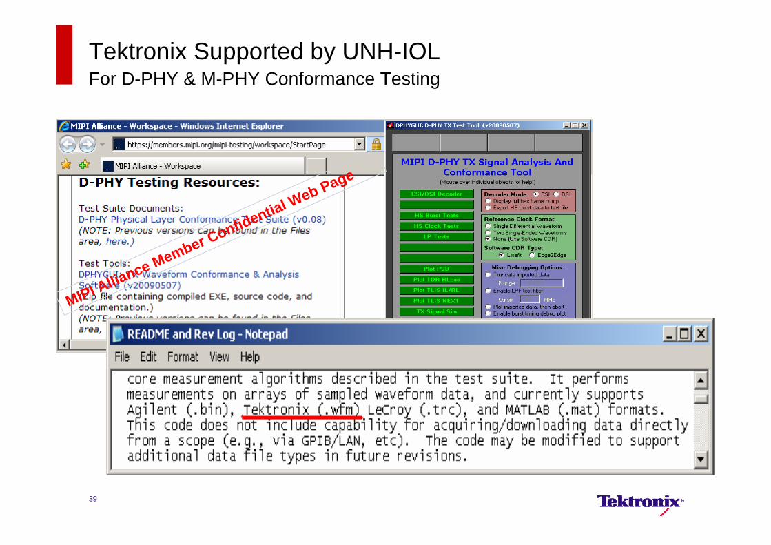
Tektronix Supported by UNH-IOLFor D-PHY & M-PHY Conformance Testing
MIPI Alliance Member Confidential Web Page
39
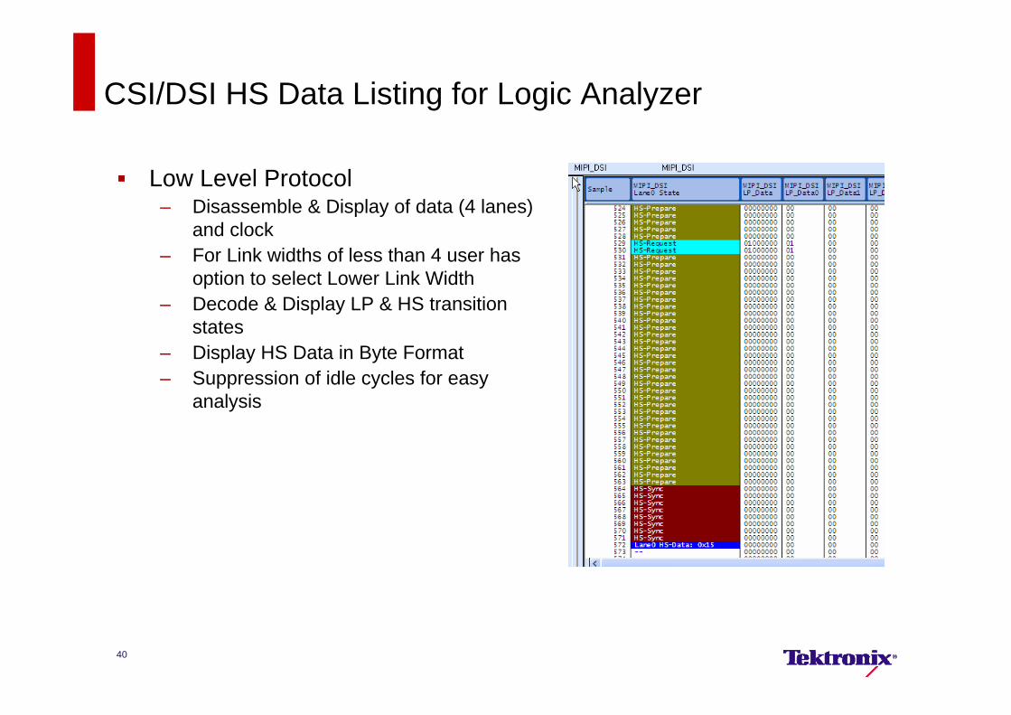
CSI/DSI HS Data Listing for Logic Analyzer
Low Level Protocol– Disassemble & Display of data (4 lanes)
and clock– For Link widths of less than 4 user has
option to select Lower Link Width– Decode & Display LP & HS transition
states– Display HS Data in Byte Format– Suppression of idle cycles for easy
analysis
40
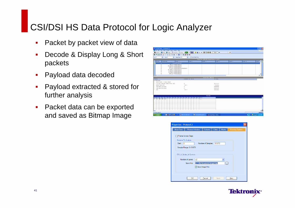
CSI/DSI HS Data Protocol for Logic Analyzer Packet by packet view of data
Decode & Display Long & Short packets
Payload data decoded
Payload extracted & stored for further analysis
Packet data can be exported and saved as Bitmap Image
41
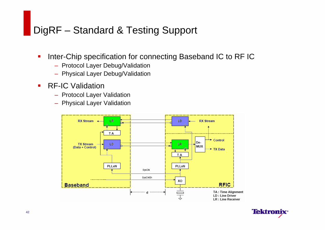
DigRF – Standard & Testing Support
Inter-Chip specification for connecting Baseband IC to RF IC– Protocol Layer Debug/Validation– Physical Layer Debug/Validation
RF-IC Validation– Protocol Layer Validation– Physical Layer Validation
42
43
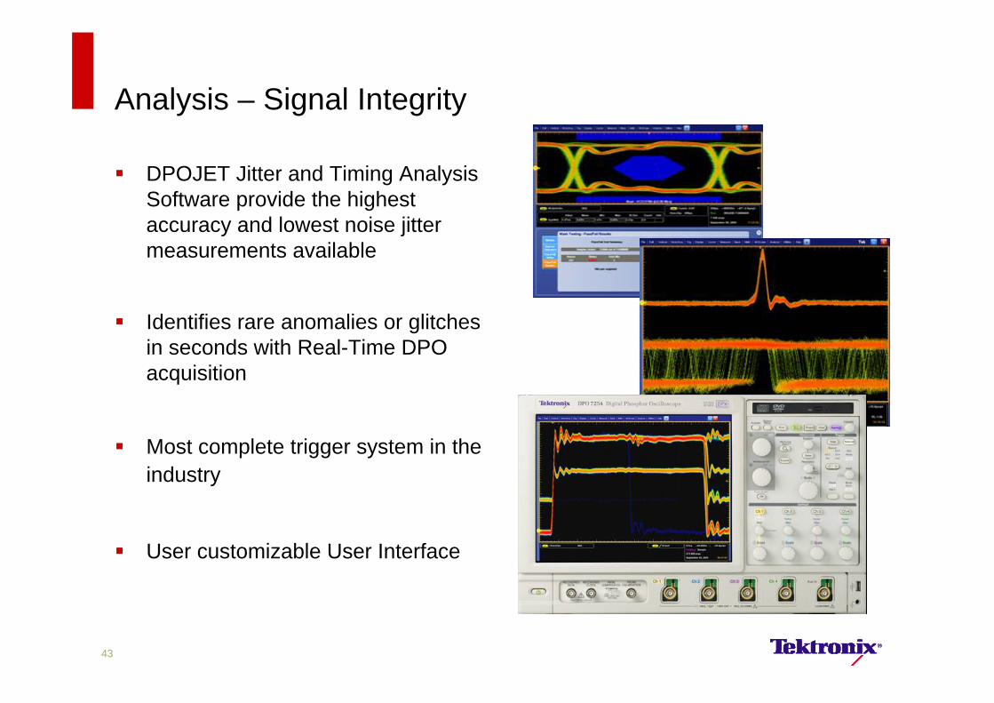
Analysis – Signal Integrity
DPOJET Jitter and Timing Analysis Software provide the highest accuracy and lowest noise jitter measurements available
Identifies rare anomalies or glitches in seconds with Real-Time DPO acquisition
Most complete trigger system in the industry
User customizable User Interface
44
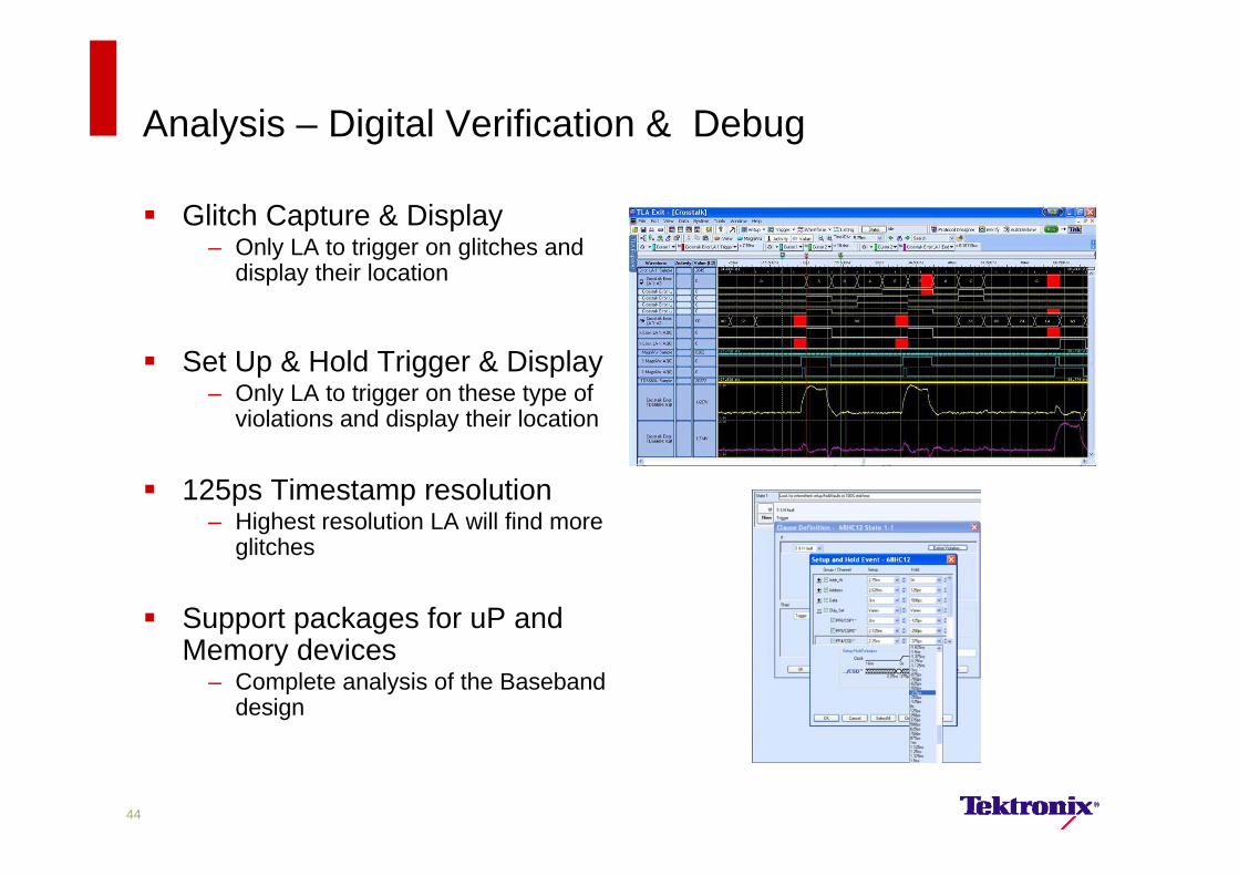
Analysis – Digital Verification & Debug
Glitch Capture & Display– Only LA to trigger on glitches and
display their location
Set Up & Hold Trigger & Display– Only LA to trigger on these type of
violations and display their location
125ps Timestamp resolution– Highest resolution LA will find more
glitches
Support packages for uP and Memory devices
– Complete analysis of the Baseband design
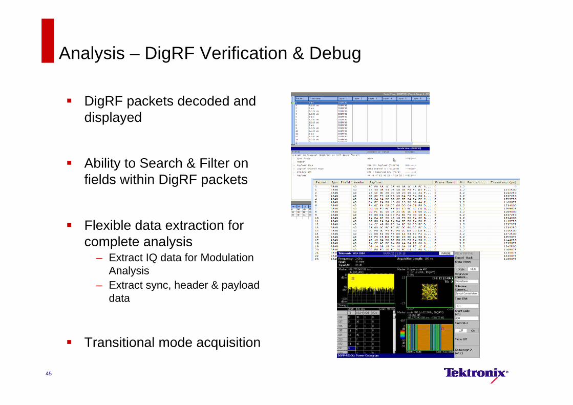
Analysis – DigRF Verification & Debug
DigRF packets decoded and displayed
Ability to Search & Filter on fields within DigRF packets
Flexible data extraction for complete analysis
– Extract IQ data for Modulation Analysis
– Extract sync, header & payload data
Transitional mode acquisition
45
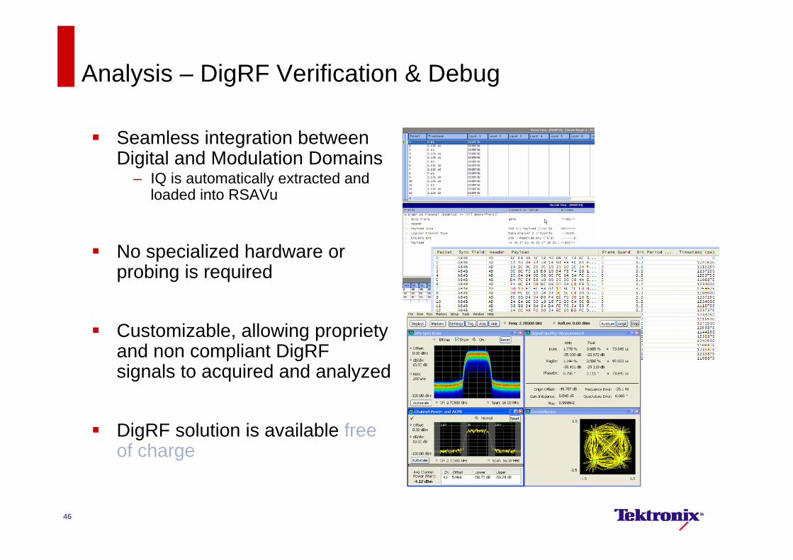
Analysis – DigRF Verification & Debug
Seamless integration between Digital and Modulation Domains
– IQ is automatically extracted and loaded into RSAVu
No specialized hardware or probing is required
Customizable, allowing propriety and non compliant DigRF signals to acquired and analyzed
DigRF solution is available free of charge
46
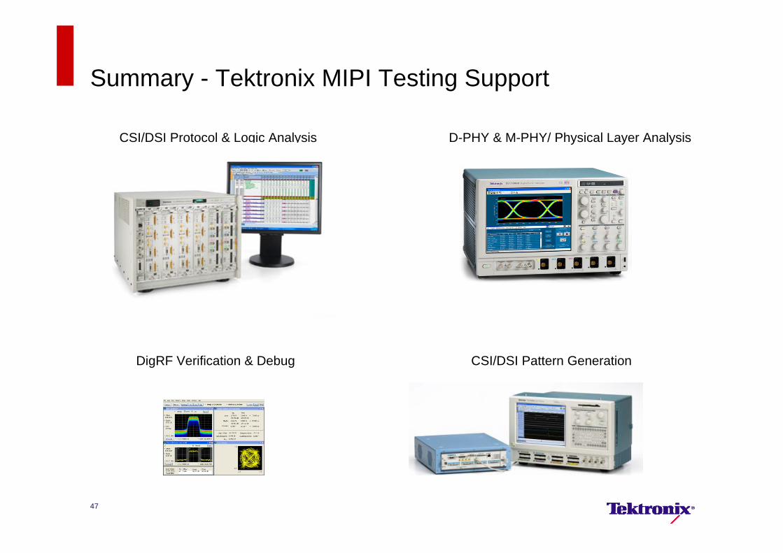
Summary - Tektronix MIPI Testing Support
CSI/DSI Protocol & Logic Analysis
CSI/DSI Pattern Generation
D-PHY & M-PHY/ Physical Layer Analysis
47
DigRF Verification & Debug
Additional Referenceswww.Tek.com/MIPI: D-PHY Datasheet
D-PHY/ CSI/ DSI Application Note
DigRF Application Note– http://www2.tek.com/cmswpt/tidetails.lotr?ct=TI&cs=tbr&ci=11854&lc=EN
Fact Sheet:– http://www2.tek.com/cmswpt/pidetails.lotr?ct=PI&cs=psa&ci=15031&lc=EN
Opt. D-PHY MOI– http://www.tek.com/applications/computing/serial/recommended_equipment.html#mipi
DPOJET Analysis Tool– http://www2.tek.com/cmsreplive/psrep/13555/61W_21170_3_2010.04.16.08.11.57_13555_EN.pdf
Other: D-PHY Conformance Test Spec (CTS):
– Rev 0.98: https://members.mipi.org/mipi-testing/file/UNH-IOL/UNH-IOL%20Test%20Suite%20Documents/DPHY/MIPI_D-PHY_Conformance_Test_Suite_(v0.98).pdf
– Rev 0.08: https://members.mipi.org/mipi-testing/file/UNH-IOL/UNH-IOL%20Test%20Suite%20Documents/DPHY/MIPI%20D-PHY%20Conformance%20Test%20Suite%20(v0.08).doc
MIPI Alliance Video on Tek Solutions http://www.youtube.com/watch?v=Mf9rv-X2YG4&feature=channel
48
Thank You
Recommended