I/O Command Type Servo Motor Inherits Strongest Servo Core
MINAS A4PSeriesMINAS A4PSeries
Achieves System Simplification and Cost Reduction
• NC functions allow positioning by I/O command only.• A target can be positioned (by teaching) without complicated pulse calculations.• In addition to travel distances, point tables combine 16 types of preset speeds, linear
acceleration/deceleration or S-shaped acceleration/deceleration, and 4 types of acceleration and deceleration.
• Two types of continuous operations are available depending on required machine specifications; continuous positioning with a temporary stop at any point and a combined block operation without a temporary stop.
• Sequential operation can be set to execute a maximum of 60 positioning points automatically.• 8 types of homing operation modes are available. If a bumping homing is selected,
simplified return-to-origin can be executed without any origin sensor.
• A maximum of 60 positioning points can be stored. No complicated programming is required as before.• Positioning points can be specified as absolute positions or relative positions.• Positioning can be performed directly at an absolute position without requiring homing
operation by using the MINAS A4P as an absolute encoder in combination with a motor equipped with a 17-bit absolute/incremental encoder.
I/O Command Type Servo Motor Inherits Strongest Servo Core
.Built-in NC Functions1
2 Neither a positioning unit nor a pulse generator is required.
A4-53
22/11/2012
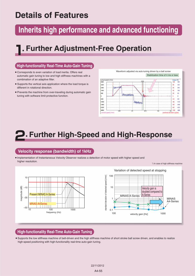
Velocity gain is doubled compared to A-Series
Variation of detected speed at stopping
stan
dard
dev
iatio
n of
det
ecte
d sp
eed
[r/m
in]
velocity gain [Hz]
100
10
1
0.1100
MINAS A-SeriesMINASA4-Series
Details of Features
Present MINAS A-Series
MINAS-A4Series
10
–10
–30
–5010
frequency (Hz)
mag
nitu
de (
dB)
Inherits high performance and advanced functioning
100 1000
1000
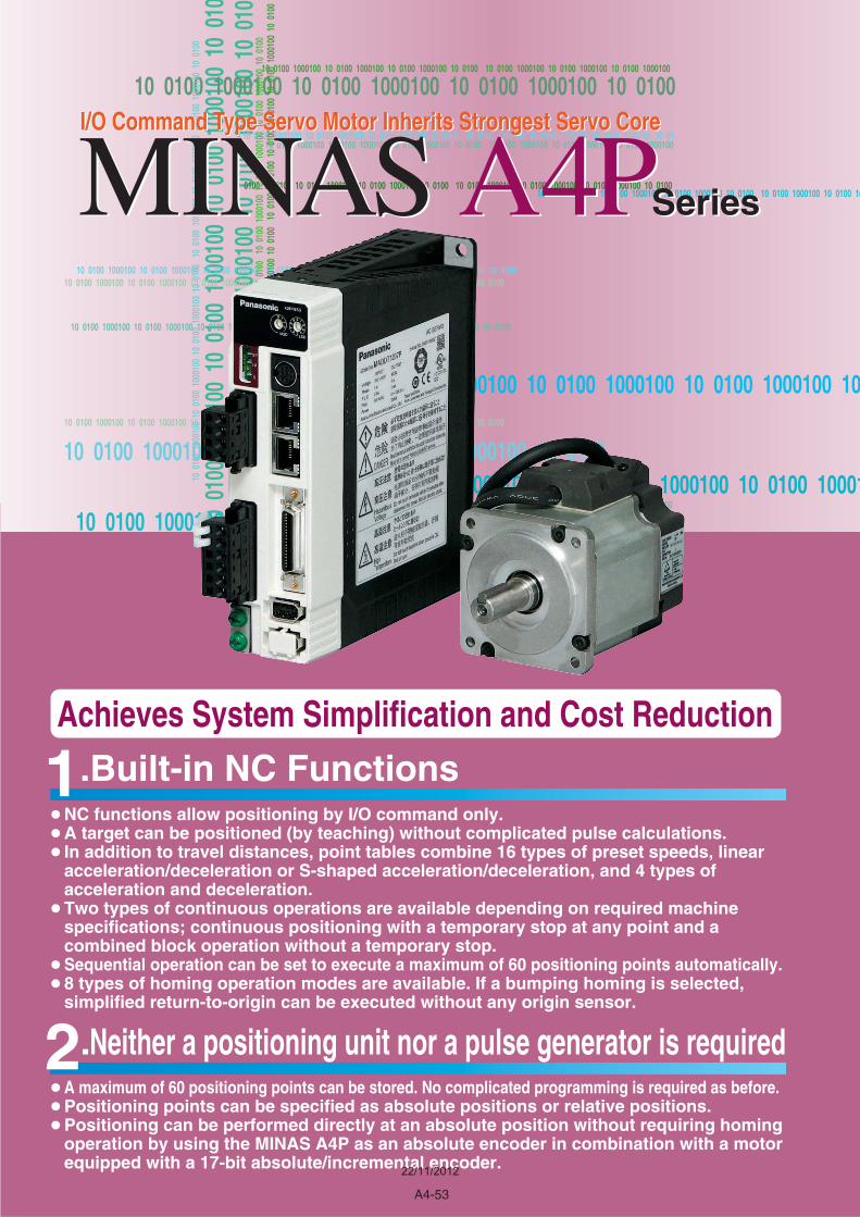
Waveform adjusted via auto-tuning driven by a ball screw
Stabilization time of 4 ms or less
High-functionality Real-Time Auto-Gain Tuning
• Corresponds to even variation of load inertia. Offers real automatic gain tuning to low and high stiffness machines with a combination of an adaptive filter.
• Supports the vertical axis application where the load torque is different in rotational direction.
• Prevents the machine from over-traveling during automatic gain tuning with software limit protective function.
Further Adjustment-Free Operation
actual speed (r/min) torque (N)
comand speed (r/min) positional deviation (pulse)
Velocity response (bandwidth) of 1kHz
• Implementation of Instantaneous Velocity Observer realizes a detection of motor speed with higher speed and higher resolution.
High-functionality Real-Time Auto-Gain Tuning
• Supports the low stiffness machine of belt-driven and the high stiffness machine of short stroke ball screw driven, and enables to realize high-speed positioning with high-functionality real-time auto-gain tuning.
Further High-Speed and High-Response
*) In case of high stiffness machine
A4-55
22/11/2012
without damping control
with damping control
motor movement machine movement
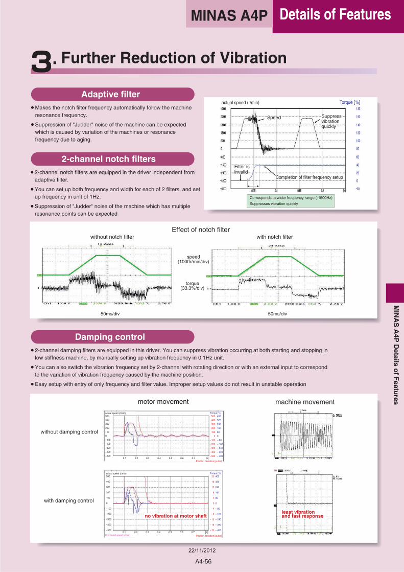
Effect of notch filterwith notch filterwithout notch filter
50ms/div
speed(1000r/min/div)
torque(33.3%/div)
50ms/div
Adaptive filter
• Makes the notch filter frequency automatically follow the machine resonance frequency.
• Suppression of "Judder" noise of the machine can be expected which is caused by variation of the machines or resonance frequency due to aging.
2-channel notch filters
• 2-channel notch filters are equipped in the driver independent from adaptive filter.
• You can set up both frequency and width for each of 2 filters, and set up frequency in unit of 1Hz.
• Suppression of "Judder" noise of the machine which has multiple resonance points can be expected
Damping control
• 2-channel damping filters are equipped in this driver. You can suppress vibration occurring at both starting and stopping in low stiffness machine, by manually setting up vibration frequency in 0.1Hz unit.
• You can also switch the vibration frequency set by 2-channel with rotating direction or with an external input to correspond to the variation of vibration frequency caused by the machine position.
• Easy setup with entry of only frequency and filter value. Improper setup values do not result in unstable operation
Further Reduction of Vibration
500
400
300
200
100
0
–100
–200
–300
–400
–500
500
400
300
200
100
0
– 100
– 200
– 300
– 400
– 500
400
320
240
160
80
0
– 80
– 160
– 240
– 320
– 400
actual speed (r/min)
500
400
300
200
100
0
–100
–200
–300
–400
–500
actual speed (r/min)
Torque [%]
Position deviation [pulse]
20
16
12
8
4
0
– 4
– 8
– 12
– 16
– 20
400
320
240
160
80
0
– 80
– 160
– 240
– 320
– 400
Torque [%]
Position deviation [pulse]Command speed (r/min)
0.1 0.2 0.3 0.4 0.5 0.6 0.7 [s]
0.1 0.2 0.3 0.4 0.5 0.6 0.7 [s]
no vibration at motor shaftleast vibration and fast response
Corresponds to wider frequency range (-1500Hz)
Suppresses vibration quickly
Filter isFilter isinvalidinvalid
SuppressSuppressvibrationvibrationquicklyquickly
SpeedSpeed
Completion of filter frequency setupCompletion of filter frequency setup
Filter isinvalid
Suppressvibrationquickly
Speed
Completion of filter frequency setup
actual speed (r/min) Torque [%]
A4-56
Details of FeaturesM
INA
SA
4PD
etailso
fF
eatures
MINAS A4P
22/11/2012
Further Flexibility and Multiplicity
Selectable Torque Limit Value
• A torque limit can be set for each rotational direction.
• According to the specification of the machine, a maximum torque can be set for each rotational direction as necessary.
Built in sequence of bumping homing
• You can select 8 kind of homing mode.
• Home sensor (based on the front end) • Home sensor + Z phase (based on the front end)• Home sensor + Z phase (based on the rear end)• Limit sensor• Limit sensor + Z phase• Z phase homing• Bumping homing• Data set
Full-closed control (High precision positioning)
• Features the full-closed control of position and velocity, using the signals from feedback scale installed on the load side and high resolution encoder.Note) Applicable feedback scales are as follows,
• Best suits to high precision machines.
Inrush current suppressing function
• Inrush suppressing resister is equipped in this driver, which prevents the circuit breaker shutdown of the power supply caused by inrush current at power-on.
• Prevents unintentional shutdown of the power supply circuit breaker
in multi-axes application and does not give load to the power line.
Setup support software
• With the setup support software, "PANATERM" via RS232 communication port, you can monitor the running status of the driver and set up parameters.
Wave-form graphic function
• With the setup support software, "PANATERM" , you can monitor the "Command speed" , "Actual speed" ,"Torque" , "Position deviation " and "Positioning complete signal" .
• Helps you to analyze the machine and shorten the setup time * Note) Refer to page "F2" for setup support software.
Dedicated Console (DV0P4420)
• Enables easy parameter setting/changing, control state monitoring, status/error log viewing, and parameter saving/loading.
• Makes it easy to move a target position, set a positioning point and perform teaching.
• Can select and display 16 types of operation data including motor rotational speed and torque in the monitor mode.
Control Mode
• Makes it possible to select position control via the motor´s internal encoder or fully-closed control based on an feedback scale.
Analog Monitor Terminal
• "Motor rotational speed", "Command speed", "torque command" and "positional deviation" can be observed by oscilloscope through the analog monitor pin at the front panel of the driver.
Trial run (JOG)
• Features the function for trial (JOG) run through console (option) without connecting to a host controller.
• You can shorten the machine setup time.
Regeneration discharging function
• Discharges the regenerative energy with resister, which energy is generated while stopping the load with large moment of inertia, or use in up-down operation, and is returned to the driver from the motor.
• No regeneration discharge resistor is built-in to Frame A driver (MADDT1105P type.) and Frame B driver (MBDDT2210P type.), and we recommend you to connect optional regenerative resistor.
• Regenerative resistor is built-in to Frame C to F drivers, however, connection of the optional regenerative resistor bring you further regenerative capability.
Built-in dynamic brake
• You can select the dynamic brake action which short the servo motor windings of U, V and W, at Servo-OFF, CW/CCW over-travel inhibition, power shutdown and trip.
• You can select the action sequence setup depending on the machine requirement.
ABS AT573A SeriesABS ST771A SeriesABS ST773A SeriesABS ST771AL SeriesABS ST773AL Series
Resolution(μm)0.050.50.10.50.1
Max. Speed*(m/s)25454
• Made by Mitsutoyo
(* The maximum speed depends on the driver performance. ) It is limited by the machine configuration and system configuration.
A4-57
22/11/2012
SEMI F47 voltage sag immunity
• Features the function which complies to voltage sag immunity standard of SEMI F47 at no load or light load.
• Useful for semiconductor industry. Notes) 1) Not applicable to single phase, 100V type. 2) Verify with the actual machine condition to F47,
voltage sag immunity standard.
Frequency analyzing function
• You can confirm the response frequency characteristics of total machine mechanism including the servo motor with the setup support software, "PANATERM"
• Helps you to analyze the machine and shorten the setup time *Note) Refer to page "F2" for setup support software.
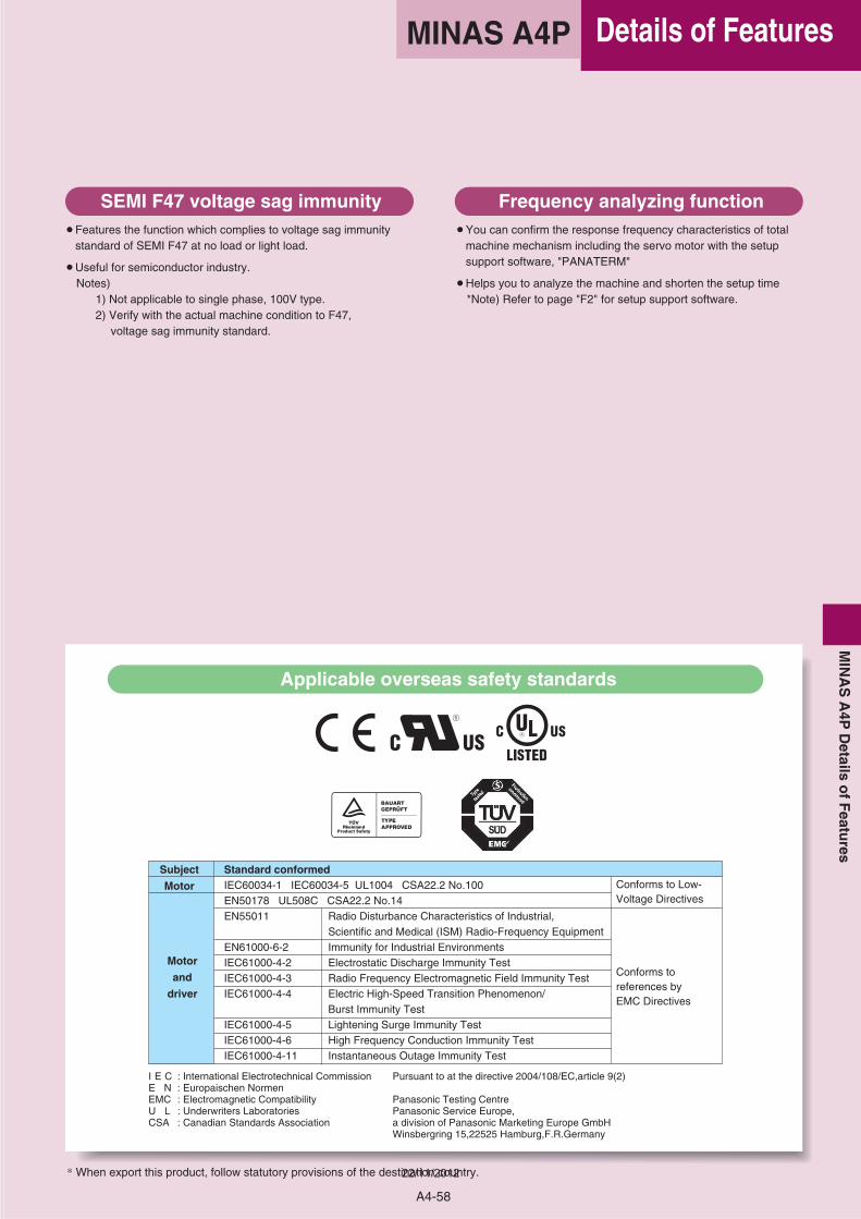
I E C : International Electrotechnical CommissionE N : Europaischen NormenEMC : Electromagnetic CompatibilityU L : Underwriters LaboratoriesCSA : Canadian Standards Association
Pursuant to at the directive 2004/108/EC,article 9(2)
Panasonic Testing CentrePanasonic Service Europe,a division of Panasonic Marketing Europe GmbHWinsbergring 15,22525 Hamburg,F.R.Germany
Applicable overseas safety standards
* When export this product, follow statutory provisions of the destination country.
Subject
Motor
Motor
and
driver
Standard conformedIEC60034-1 IEC60034-5 UL1004 CSA22.2 No.100EN50178 UL508C CSA22.2 No.14EN55011 Radio Disturbance Characteristics of Industrial,
Scientific and Medical (ISM) Radio-Frequency EquipmentEN61000-6-2 Immunity for Industrial Environments IEC61000-4-2 Electrostatic Discharge Immunity TestIEC61000-4-3 Radio Frequency Electromagnetic Field Immunity TestIEC61000-4-4 Electric High-Speed Transition Phenomenon/
Burst Immunity TestIEC61000-4-5 Lightening Surge Immunity TestIEC61000-4-6 High Frequency Conduction Immunity TestIEC61000-4-11 Instantaneous Outage Immunity Test
Conforms to Low-Voltage Directives
Conforms to references by EMC Directives
A4-58
Details of FeaturesMINAS A4PM
INA
SA
4PD
etailso
fF
eatures
22/11/2012
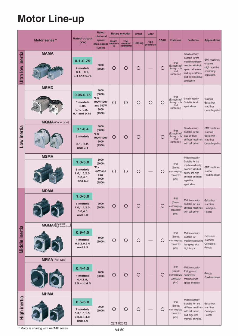
Motor Line-up
Motor series * Enclosure
IP65(Except shaftthrough hole
andconnector)
IP65(Except shaftthrough hole
andconnector)
IP65(Except shaftthrough hole
andconnector)
IP65(Except
cannon plug/connector
pins)
IP65(Except
cannon plug/connector
pins)
IP65(Except
cannon plug/connector
pins)
IP65(Except
cannon plug/connector
pins)
IP65(Except
cannon plug/connector
pins)
Features
.Small capacity
.Suitable for the machines directly coupled with high speed ball screw and high stiffness and high repetitive application
.Small capacity
.Suitable for all applications
.Small capacity
.Suitable for flat type and low stiffness machines with belt driven
.Middle capacity
.Suitable for the machines directly coupled with ball screw and high stiffness and high repetitive application
.Middle capacity
.Suitable for low stiffness machines with belt driven
.Middle capacity
.Suitable for machines requiring low speed with high torque
.Middle capacity
.Flat type and suitable for machines with space limitation
.Middle capacity
.Suitable for low stiffness machines with belt driven, and large load moment of inertia
.SMT machines
.Inserters
.High repetitive positioning application
.Inserters
.Belt driven machines.Unloading robot
.SMT machines
.Inserters
.Belt driven machines.Unloading robot
.SMT machines
.Inserter
.Food machines
.Belt driven machines.Conveyers.Robots
.Belt driven machines.Conveyers.Robots
.Robots
.Food machines
.Belt driven machines.Conveyors.Robots
Gear
High precision
2500P/r incremen
tal
17bit absolute/
incremental
Brake
Holding
Rotary encoder
ApplicationsCE/UL
Ultr
a lo
w in
ertia
Low
iner
tiaM
iddl
e in
ertia
Hig
h in
ertia
* Motor is sharing with A4/A4F series
MAMA
MSMD
MQMA (Cube type)
MSMA
MDMA
MGMA ( )
MFMA (Flat type)
MHMA
Low speed/High torque type
Rated output (kW)
0.1-0.75
4 models0.1, 0.2,
0.4 and 0.75
0.05-0.75
5 models 0.05,
0.1, 0.2, 0.4 and 0.75
0.1-0.4
3 models
0.1, 0.2, and 0.4
1.0-5.0
6 models1.0,1.5,2.0,
3.0,4.0 and 5.0
1.0-5.0
6 models1.0,1.5,2.0,
3.0,4.0and 5.0
0.9-4.5
4 models0.9,2.0,3.0
and 4.5
0.4-4.5
4 models0.4,1.5,
2.5 and 4.5
0.5-5.0
7 models0.5,1.0,1.5,2.0,3.0,4.0
and 5.0
Ratedrotational
speed(Max. speed)
(r/min)
5000(6000)
3000(5000)
*For 400W/100Vand 750W
3000(4500)
3000(5000)
*For 400W/100V
3000(4500)
3000(5000)
*For 4kW and
5kW3000
(4500)
2000(3000)
1000(2000)
2000(3000)
2000(3000)
A4-59
22/11/2012
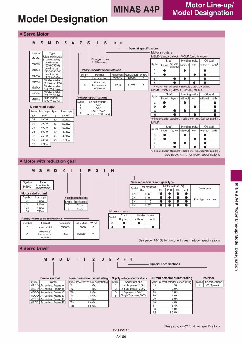
Voltage specifications
Gear reduction ration, gear type
Motor rated output
Motor structure
Rotary encoder specifications
7SAbsolute/
Incrementalcommon
17bit 131072
Wires
P Incremental 2500P/r 10000 5
Symbol Format Pulse counts Resolution
4
3without withKey-way
SymbolShaft Holding brake
4N 1 / 25
Symbol01020408
Rated output100W200W400W750W
3N 1 / 15For high accuracy
2N 1 / 9
7501N 1 / 5
Motor output (W)Gear type(100W-750W)
100 200 400
Symbol12
Specifications100V200V
Symbol Gear reductionratio
Symbol
MSMD
TypeLow inertia
M S M D 0 1 1 P 3 1 N
• Servo Motor
• Motor with reduction gear
• Servo Driver
See page, A4-133 for motor with gear reducer specifications
Model Designation
Special specifications
Frame symbolSymbolMADD A4 series, Frame AMBDD A4 series, Frame BMCDD A4 series, Frame CMDDD A4 series, Frame DMEDD A4 series, Frame EMFDD A4 series, Frame F
Frame SymbolT1T2T3T5T7TATB
Power device Max. current rating
1 0 0A1 5 0A
7 5A
1 5A3 0A5 0A
Power device Max. current rating1 0A
Symbol1235
Supply voltage specifications
Single/3-phase,200V
Single phase, 200V3-phase, 200V
SpecificationsSingle phase, 100V
Design order1 : Standard
Voltage specifications
Symbol12
Specifications
Z
100V200V
100V/200Vcommon(50W only)
Motor rated output
Symbol
20
30
40
45
50
2.0kW
3.0kW
4.0kW
4.5kW
5.0kW
Rated output
15 1.5kW
10 1.0kW
09
500W
750W
900W
05
08
02
04
50W100W
200W 25 2.5kW400W
015A
Symbol Rated output
MAMA
MSMD
Ultra low inertia(100W-750W)Low inertia(50W-750W)
Type
Low inertia(100W-400W)Low inertia(1.0kW-5.0W)Middle inertia (1.0kW-5.0kW)
Middle inertia(400W-4.5kW)
Middle inertia(900W-4.5kW)
Symbol
MQMA
MSMA
MDMA
MGMA
MFMA
MHMA High inertia(500W-5.0kW)
Rotary encoder specifications
SymbolP
S
ResolutionFormatIncremental
Absolute/Incremental
common
5
7
2500P/r
17bit
10000
131072
WiresPulse counts
Symbol0507102030406490A2
4 0A6 4A9 0A
1 2 0A
7.5A1 0A2 0A3 0A
Current detector, current rating5A
Current detector current rating Interface
See page, A4-77 for motor specifications
See page, A4-67 for driver specifications
Special specificationsMotor structureMSMD(standard stock), MQMA(build to order)
A
B
Motor with oil seal is manufactured by order.
Symbol
ST
without with withwithout
Shaft Holding brake Oil sealKey-way, center tap
MSMA , MDMA , MGMA , MFMA , MHMA
GH
CD
Holding brake
with
Oil sealSymbol
Shaft
without withwithoutRound
Round
Key-way
MAMA
ABEF
SymbolShaft Holding brake Oil seal
Round Key-way without with without with
Products are standard stock items or build to order items. See index (page F31).
Products are standard stock items or build to order items. See index (page F31).
M S M D 5 A Z S 1 S
M A D D T 1 2 0 5 P
SymbolP
SpecificationsI/O Operation
A4-60
Motor Line-up/Model DesignationMINAS A4P
MIN
AS
A4P
Mo
tor
Lin
e-up
/Mo
delD
esign
ation
22/11/2012
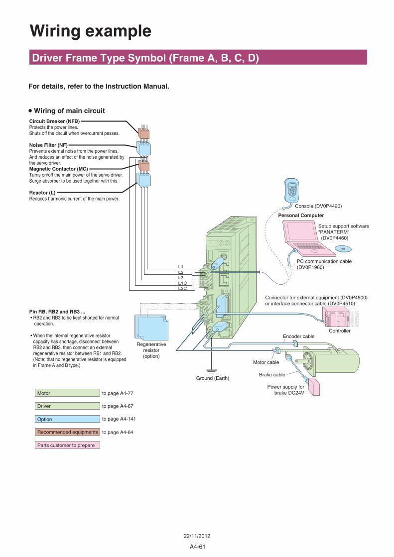
• Wiring of main circuit
For details, refer to the Instruction Manual.
Circuit Breaker (NFB)Protects the power lines.Shuts off the circuit when overcurrent passes.
Noise Filter (NF)Prevents external noise from the power lines. And reduces an effect of the noise generated by the servo driver.Magnetic Contactor (MC)Turns on/off the main power of the servo driver. Surge absorber to be used together with this.
Reactor (L)Reduces harmonic current of the main power.
Pin RB, RB2 and RB3 ... • RB2 and RB3 to be kept shorted for normal operation.
• When the internal regenerative resistor capacity has shortage, disconnect between RB2 and RB3, then connect an external regenerative resistor between RB1 and RB2.(Note: that no regenerative resistor is equipped in Frame A and B type.)
Regenerativeresistor(option)
Ground (Earth)
Motor cable
Personal Computer
Setup support software"PANATERM" (DV0P4460)
PC communication cable(DV0P1960)
Connector for external equipment (DV0P4500)or interface connector cable (DV0P4510)
Driver Frame Type Symbol (Frame A, B, C, D)
Wiring example
Controller
Console (DV0P4420)
Encoder cable
Brake cable
Power supply forbrake DC24Vto page A4-77
to page A4-67
to page A4-141
to page A4-64
Driver
Option
Recommended equipments
Parts customer to prepare
Motor
M
S
L1L2L3L1CL2C
A4-61
22/11/2012
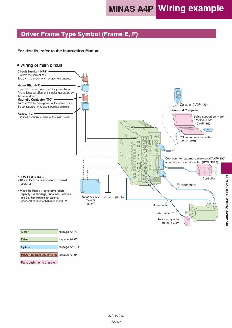
For details, refer to the Instruction Manual.
• Wiring of main circuit
Driver Frame Type Symbol (Frame E, F)
Circuit Breaker (NFB)Protects the power lines.Shuts off the circuit when overcurrent passes.
Noise Filter (NF)Prevents external noise from the power lines. And reduces an effect of the noise generated by the servo driver.Magnetic Contactor (MC)Turns on/off the main power of the servo driver. Surge absorber to be used together with this.
Reactor (L)Reduces harmonic current of the main power.
Pin P, B1 and B2 ... • B1 and B2 to be kept shorted for normal operation.
• When the internal regenerative resistor capacity has shortage, disconnect between B1 and B2, then connect an external regenerative resistor between P and B2.
Regenerativeresistor(option)
Ground (Earth)
Motor cable
Personal Computer
PC communication cable(DV0P1960)
Connector for external equipment (DV0P4500)or interface connector cable (DV0P4510)
Controller
Encoder cable
Brake cable
Power supply forbrake DC24V
Motor to page A4-77
to page A4-67
to page A4-141
to page A4-64
Driver
Option
Recommended equipments
Parts customer to prepare
Setup support software"PANATERM" (DV0P4460)
Console (DV0P4420)
M
S
A4-62
Wiring exampleMINAS A4PM
INA
SA
4PW
iring
examp
le
22/11/2012
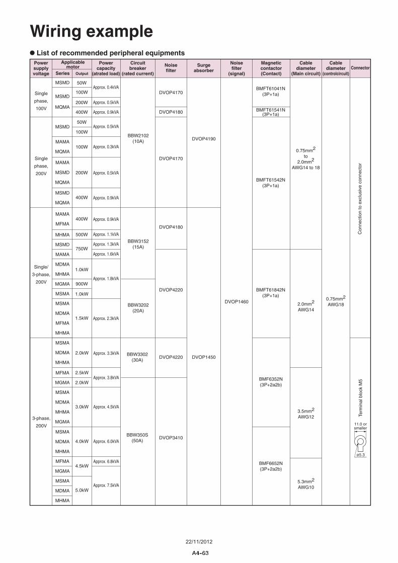
Wiring example• List of recommended peripheral equipments
4.0kW
2.5kW
3-phase,
200V
4.5kW
BMF6352N(3P+2a2b)
BMF6652N(3P+2a2b)
DVOP4220BBW3302
(30A)
Approx. 4.5kVA
Approx. 3.3kVA
Approx. 3.8kVA
Approx. 6.0kVA
Approx. 6.8kVA
Approx. 7.5kVA
BBW350S(50A)
DVOP3410
5.0kW
2.0kW
3.0kW
2.0kW
5.3mm2
AWG10
3.5mm2
AWG12
Applicablemotor
Powersupplyvoltage
Magneticcontactor(Contact)
Cablediameter
(Main circuit)
Cablediameter
(controlcircuit)OutputSeries
Noisefilter
Surgeabsorber
Noisefilter
(signal)
Circuitbreaker
(rated current)
Powercapacity
(atrated load)
Single
phase,
200V
Single
phase,
100V200W
400W
400W
BMFT61041N(3P+1a)
BMFT61541N(3P+1a)
BMFT61542N(3P+1a)
DVOP4170
BBW2102(10A)
Approx. 0.3kVA
Approx. 0.4kVA
Approx. 0.5kVA
Approx. 0.5kVA
Approx. 0.5kVA
Approx. 0.9kVA
Approx. 0.9kVA
DVOP4180
DVOP4170
100W
100W
200W
100W
50W
50W
DVOP4190
Connector
0.75mm2
to2.0mm2
AWG14 to 18
400W
Single/
3-phase,
200V
1.5kW
500W
1.0kW
1.0kW
0.75mm2
AWG18
BMFT61842N(3P+1a)
DVOP4220
Approx. 0.9kVA
Approx. 1.1kVA
Approx. 1.6kVA
Approx. 1.3kVA
Approx. 1.8kVA
Approx. 2.3kVA
BBW3152(15A)
BBW3202(20A)
750W
DVOP4180
900W
MSMA
MGMA
MDMA
MDMA
MSMA
MSMA
MDMA
MHMA
MDMA
MHMA
MGMA
MSMA
MHMA
MFMA
MHMA
MFMA
MGMA
MSMD
MSMD
MAMA
MAMA
MSMD
MQMA
MSMD
MQMA
MSMD
MQMA
MQMA
MAMA
MSMD
MSMA
MSMA
MDMA
MAMA
MGMA
MDMA
MHMA
MFMA
MHMA
MFMA
MHMA
DVOP1450
DVOP1460
Con
nect
ion
to e
xclu
sive
con
nect
or
2.0mm2
AWG14
11.0 orsmaller
ø5.3
Term
inal
blo
ck M
5
22/11/2012
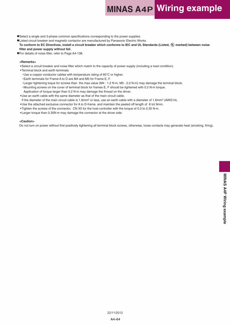
•Select a single and 3-phase common specifications corresponding to the power supplies.
•Listed circuit breaker and magnetic contactor are manufactured by Panasonic Electric Works.To conform to EC Directives, install a circuit breaker which conforms to IEC and UL Standards (Listed, marked) between noise filter and power supply without fail.
•For details of noise filter, refer to Page A4-138.
<Remarks> •Select a circuit breaker and noise filter which match to the capacity of power supply (including a load condition). •Terminal block and earth terminals
• Use a copper conductor cables with temperature rating of 60˚C or higher.• Earth terminals for Frame A to D are M4 and M5 for Frame E, F.• Larger tightening toque for screws than the max.value (M4 : 1.2 N·m, M5 : 2.0 N·m) may damage the terminal block.• Mounting screws on the cover of terminal block for frames E, F should be tightened with 0.2 N·m torque.Application of torque larger than 0.2 N·m may damage the thread on the driver.
•Use an earth cable with the same diameter as that of the main circuit cable.If the diameter of the main circuit cable is 1.6mm2 or less, use an earth cable with a diameter of 1.6mm2 (AWG14).
•Use the attached exclusive connector for A to D-frame, and maintain the peeled off length of 8 tot 9mm. •Tighten the screws of the connector, CN X5 for the host controller with the torque of 0.3 to 0.35 N·m. •Larger torque than 0.35N·m may damage the connector at the driver side.
<Caution>Do not turn on power without first positively tightening all terminal block screws, otherwise, loose contacts may generate heat (smoking, firing).
Wiring exampleMINAS A4PM
INA
SA
4PW
iring
examp
le
22/11/2012
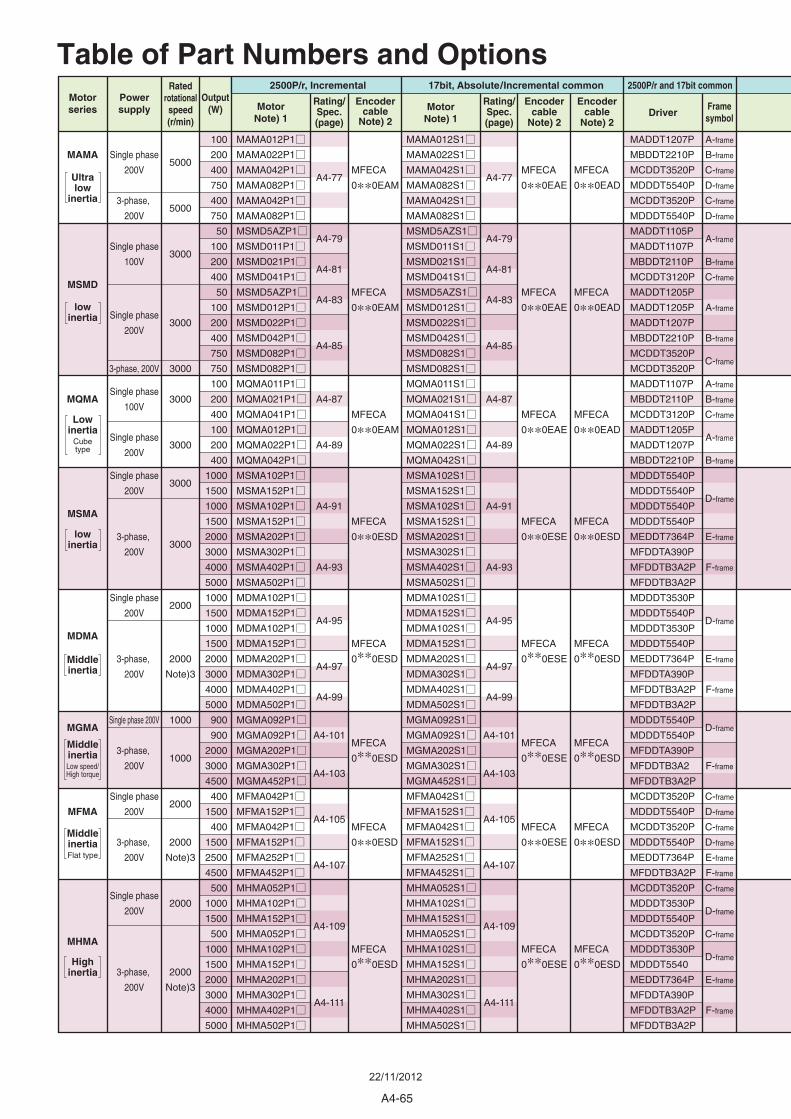
Table of Part Numbers and OptionsPowersupply
Motorseries Driver
Rating/Spec.(page)
Framesymbol
Encodercable
Note) 2
17bit, Absolute/Incremental common
Encodercable
Note) 2
2500P/r and 17bit commonOutput
(W)Rating/Spec.(page)
Ratedrotationalspeed(r/min)
MotorNote) 1
MotorNote) 1
Encodercable
Note) 2
2500P/r, Incremental
MAMA
MSMD
MQMA
MSMA
MDMA
MGMA
MFMA
MHMA
Single phase
200V
3-phase,
200V
Single phase
100V
Single phase
200V
3-phase, 200V
Single phase
100V
Single phase
200V
Single phase
200V
3-phase,
200V
Single phase
200V
3-phase,
200V
Single phase 200V
3-phase,
200V
Single phase
200V
3-phase,
200V
Single phase
200V
3-phase,
200V
100
200
400
750
400
750
50
100
200
400
50
100
200
400
750
750
100
200
400
100
200
400
1000
1500
1000
1500
2000
3000
4000
5000
1000
1500
1000
1500
2000
3000
4000
5000
900
900
2000
3000
4500
400
1500
400
1500
2500
4500
500
1000
1500
500
1000
1500
2000
3000
4000
5000
MAMA012P1
MAMA022P1
MAMA042P1
MAMA082P1
MAMA042P1
MAMA082P1
MSMD5AZP1
MSMD011P1
MSMD021P1
MSMD041P1
MSMD5AZP1
MSMD012P1
MSMD022P1
MSMD042P1
MSMD082P1
MSMD082P1
MQMA011P1
MQMA021P1
MQMA041P1
MQMA012P1
MQMA022P1
MQMA042P1
MSMA102P1
MSMA152P1
MSMA102P1
MSMA152P1
MSMA202P1
MSMA302P1
MSMA402P1
MSMA502P1
MDMA102P1
MDMA152P1
MDMA102P1
MDMA152P1
MDMA202P1
MDMA302P1
MDMA402P1
MDMA502P1
MGMA092P1
MGMA092P1
MGMA202P1
MGMA302P1
MGMA452P1
MFMA042P1
MFMA152P1
MFMA042P1
MFMA152P1
MFMA252P1
MFMA452P1
MHMA052P1
MHMA102P1
MHMA152P1
MHMA052P1
MHMA102P1
MHMA152P1
MHMA202P1
MHMA302P1
MHMA402P1
MHMA502P1
A4-77
A4-79
A4-81
A4-83
A4-85
A4-87
A4-89
A4-91
A4-93
A4-95
A4-97
A4-99
A4-101
A4-103
A4-105
A4-107
A4-109
A4-111
MFECA
0**0EAM
MFECA
0**0EAM
MFECA
0**0EAM
MFECA
0**0ESD
MFECA
0**0ESD
MFECA
0**0ESD
MFECA
0**0ESD
MFECA
0**0ESD
A4-77
A4-79
A4-81
A4-83
A4-85
A4-87
A4-89
A4-91
A4-93
A4-95
A4-97
A4-99
A4-101
A4-103
A4-105
A4-107
A4-109
A4-111
MFECA
0**0EAE
MFECA
0**0EAE
MFECA
0**0EAE
MFECA
0**0ESE
MFECA
0**0ESE
MFECA
0**0ESE
MFECA
0**0ESE
MFECA
0**0ESE
MFECA
0**0EAD
MFECA
0**0EAD
MFECA
0**0EAD
MFECA
0**0ESD
MFECA
0**0ESD
MFECA
0**0ESD
MFECA
0**0ESD
MFECA
0**0ESD
A-frame
B-frame
C-frame
D-frame
C-frame
D-frame
A-frame
B-frame
C-frame
A-frame
B-frame
C-frame
A-frame
B-frame
C-frame
A-frame
B-frame
D-frame
E-frame
F-frame
D-frame
E-frame
F-frame
D-frame
F-frame
C-frame
D-frame
C-frame
D-frame
E-frame
F-frame
C-frame
D-frame
C-frame
D-frame
E-frame
F-frame
MADDT1207P
MBDDT2210P
MCDDT3520P
MDDDT5540P
MCDDT3520P
MDDDT5540P
MADDT1105P
MADDT1107P
MBDDT2110P
MCDDT3120P
MADDT1205P
MADDT1205P
MADDT1207P
MBDDT2210P
MCDDT3520P
MCDDT3520P
MADDT1107P
MBDDT2110P
MCDDT3120P
MADDT1205P
MADDT1207P
MBDDT2210P
MDDDT5540P
MDDDT5540P
MDDDT5540P
MDDDT5540P
MEDDT7364P
MFDDTA390P
MFDDTB3A2P
MFDDTB3A2P
MDDDT3530P
MDDDT5540P
MDDDT3530P
MDDDT5540P
MEDDT7364P
MFDDTA390P
MFDDTB3A2P
MFDDTB3A2P
MDDDT5540P
MDDDT5540P
MFDDTA390P
MFDDTB3A2
MFDDTB3A2P
MCDDT3520P
MDDDT5540P
MCDDT3520P
MDDDT5540P
MEDDT7364P
MFDDTB3A2P
MCDDT3520P
MDDDT3530P
MDDDT5540P
MCDDT3520P
MDDDT3530P
MDDDT5540
MEDDT7364P
MFDDTA390P
MFDDTB3A2P
MFDDTB3A2P
5000
5000
3000
3000
3000
3000
3000
3000
3000
2000
2000
Note)3
1000
1000
2000
2000
Note)3
2000
2000
Note)3
MAMA012S1
MAMA022S1
MAMA042S1
MAMA082S1
MAMA042S1
MAMA082S1
MSMD5AZS1
MSMD011S1
MSMD021S1
MSMD041S1
MSMD5AZS1
MSMD012S1
MSMD022S1
MSMD042S1
MSMD082S1
MSMD082S1
MQMA011S1
MQMA021S1
MQMA041S1
MQMA012S1
MQMA022S1
MQMA042S1
MSMA102S1
MSMA152S1
MSMA102S1
MSMA152S1
MSMA202S1
MSMA302S1
MSMA402S1
MSMA502S1
MDMA102S1
MDMA152S1
MDMA102S1
MDMA152S1
MDMA202S1
MDMA302S1
MDMA402S1
MDMA502S1
MGMA092S1
MGMA092S1
MGMA202S1
MGMA302S1
MGMA452S1
MFMA042S1
MFMA152S1
MFMA042S1
MFMA152S1
MFMA252S1
MFMA452S1
MHMA052S1
MHMA102S1
MHMA152S1
MHMA052S1
MHMA102S1
MHMA152S1
MHMA202S1
MHMA302S1
MHMA402S1
MHMA502S1
Ultralow
inertia
Lowinertia
Cubetype
MiddleinertiaFlat type
lowinertia
lowinertia
Middleinertia
MiddleinertiaLow speed/High torque
Highinertia
A4-65
22/11/2012
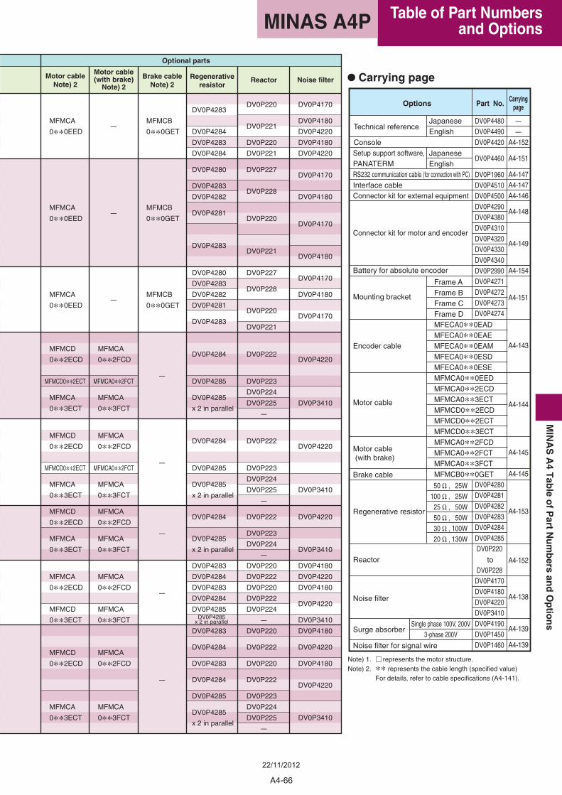
Part No.OptionsCarrying
page
Single phase 100V, 200V3-phase 200V
50 Ω , 25W100 Ω , 25W
25 Ω , 50W50 Ω , 50W30 Ω , 100W20 Ω , 130W
• Carrying page
Note) 1. represents the motor structure.Note) 2. ** represents the cable length (specified value)
For details, refer to cable specifications (A4-141).
JapaneseEnglish
Technical reference
ConsoleJapaneseEnglish
MFECA0**0EADMFECA0**0EAEMFECA0**0EAMMFECA0**0ESDMFECA0**0ESEMFMCA0**0EEDMFMCA0**2ECDMFMCA0**3ECTMFMCD0**2ECDMFMCD0**2ECTMFMCD0**3ECTMFMCA0**2FCDMFMCA0**2FCTMFMCA0**3FCTMFMCB0**0GET
Setup support software, PANATERMRS232 communication cable (for connection with PC)Interface cableConnector kit for external equipment
Connector kit for motor and encoder
Battery for absolute encoder
Mounting bracket
Encoder cable
Motor cable
Motor cable (with brake)
Brake cable
Regenerative resistor
Reactor
Noise filter
Surge absorber
Noise filter for signal wire
Frame AFrame BFrame CFrame D
DV0P1960DV0P4510DV0P4500DV0P4290DV0P4380DV0P4310DV0P4320DV0P4330DV0P4340DV0P2990DV0P4271DV0P4272DV0P4273DV0P4274
DV0P4280DV0P4281DV0P4282DV0P4283DV0P4284DV0P4285DV0P220
DV0P228DV0P4170DV0P4180DV0P4220DV0P3410DV0P4190DV0P1450DV0P1460
–
–
A4-152
A4-151
A4-147A4-147A4-146
A4-148
A4-149
A4-154
A4-151
A4-143
A4-144
A4-145
A4-145
A4-153
A4-152
A4-138
A4-139
A4-139
DV0P4480DV0P4490DV0P4420
DV0P4460
to
Motor cableNote) 2
Motor cable(with brake)
Note) 2
Brake cableNote) 2
Regenerativeresistor
Reactor Noise filter
Optional parts
MFMCB
0**0GET
MFMCB
0**0GET
MFMCB
0**0GET
–
–
–
–
–
–
–
–
MFMCA
0**2FCD
MFMCA0**2FCT
MFMCA
0**3FCT
MFMCA
0**2FCD
MFMCA0**2FCT
MFMCA
0**3FCT
MFMCA
0**2FCD
MFMCA
0**3FCT
MFMCA
0**2FCD
MFMCA
0**3FCT
MFMCA
0**2FCD
MFMCA
0**3FCT
MFMCA
0**0EED
MFMCA
0**0EED
MFMCA
0**0EED
MFMCD
0**2ECD
MFMCD0**2ECT
MFMCA
0**3ECT
MFMCD
0**2ECD
MFMCD0**2ECT
MFMCA
0**3ECT
MFMCD
0**2ECD
MFMCA
0**3ECT
MFMCA
0**2ECD
MFMCD
0**3ECT
MFMCD
0**2ECD
MFMCA
0**3ECT
DV0P4170
DV0P4180
DV0P4220
DV0P4180
DV0P4220
DV0P4170
DV0P4180
DV0P4170
DV0P4180
DV0P4170
DV0P4180
DV0P4170
DV0P4220
DV0P3410
DV0P4220
DV0P3410
DV0P4220
DV0P3410
DV0P4180
DV0P4220
DV0P4180
DV0P4220
DV0P3410
DV0P4180
DV0P4220
DV0P4180
DV0P4220
DV0P3410
DV0P220
DV0P221
DV0P220
DV0P221
DV0P227
DV0P228
DV0P220
DV0P221
DV0P227
DV0P228
DV0P220
DV0P221
DV0P222
DV0P223
DV0P224
DV0P225
–
DV0P222
DV0P223
DV0P224
DV0P225
–
DV0P222
DV0P223
DV0P224
–
DV0P220
DV0P222
DV0P220
DV0P222
DV0P224
–
DV0P220
DV0P222
DV0P220
DV0P222
DV0P223
DV0P224
DV0P225
–
DV0P4283
DV0P4284
DV0P4283
DV0P4284
DV0P4280
DV0P4283
DV0P4282
DV0P4281
DV0P4283
DV0P4280
DV0P4283
DV0P4282
DV0P4281
DV0P4283
DV0P4284
DV0P4285
DV0P4285
x 2 in parallel
DV0P4284
DV0P4285
DV0P4285
x 2 in parallel
DV0P4284
DV0P4285
x 2 in parallel
DV0P4283
DV0P4284
DV0P4283
DV0P4284
DV0P4285
DV0P4283
DV0P4284
DV0P4283
DV0P4284
DV0P4285
DV0P4285
x 2 in parallel
DV0P4285x 2 in parallel
A4-66
Table of Part Numbers and OptionsMINAS A4P
MIN
AS
A4
Tab
leo
fP
artN
um
bers
and
Op
tion
s
22/11/2012
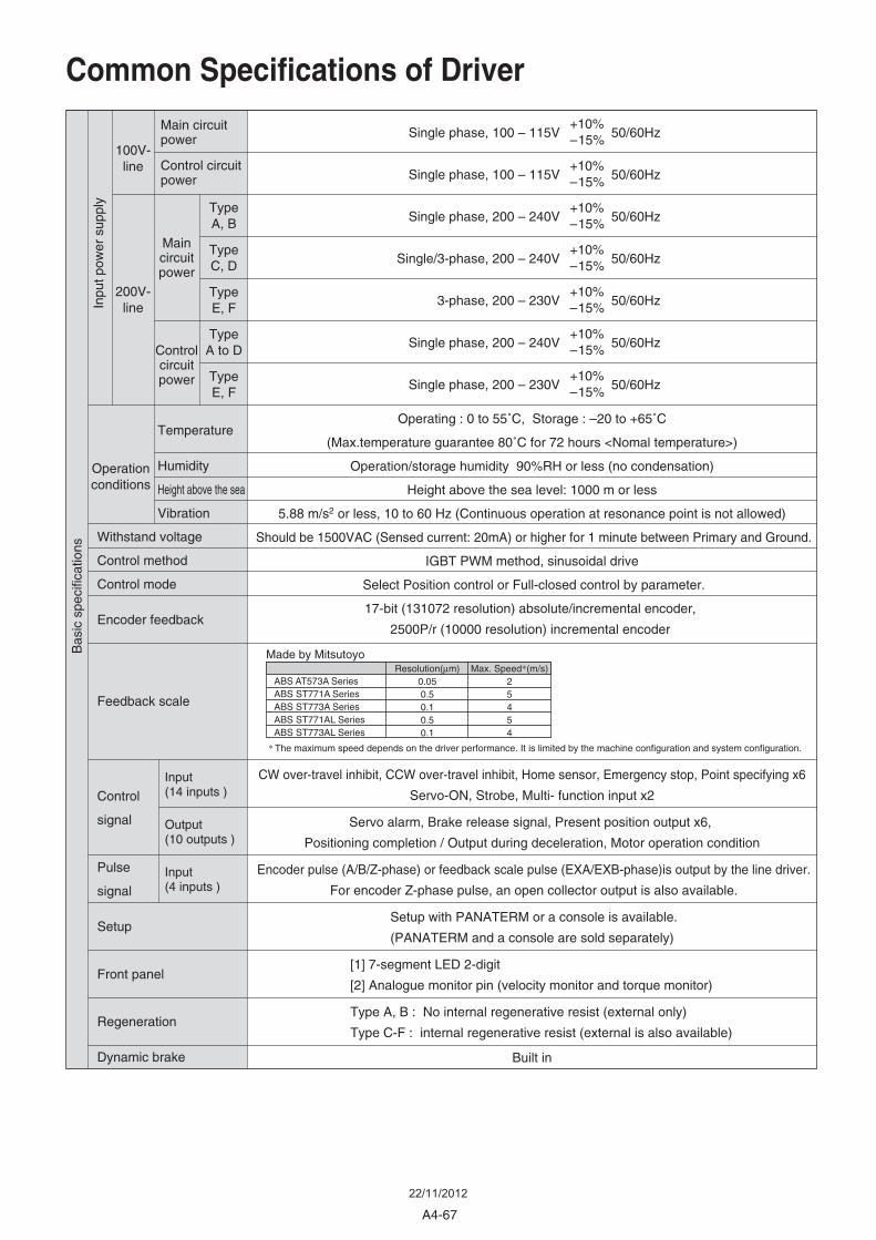
Common Specifications of DriverIn
put p
ower
sup
ply
Operationconditions
Withstand voltage
Control method
Control mode
Encoder feedback
Feedback scale
Control
signal
Pulse
signal
Setup
Front panel
Regeneration
Dynamic brake
100V-line
200V-line
Main circuitpower
Control circuitpower
Maincircuitpower
Controlcircuitpower
TypeA, B
TypeC, D
TypeE, F
TypeA to D
TypeE, F
Bas
ic s
peci
ficat
ions
Temperature
Humidity
Height above the sea
Vibration
Input(14 inputs )
Output(10 outputs )
Input(4 inputs )
+10%–15%Single phase, 200 – 230V 50/60Hz
+10%–15%Single phase, 200 – 240V 50/60Hz
+10%–15%3-phase, 200 – 230V 50/60Hz
+10%–15%Single/3-phase, 200 – 240V 50/60Hz
+10%–15%Single phase, 200 – 240V 50/60Hz
+10%–15%Single phase, 100 – 115V 50/60Hz
+10%–15%Single phase, 100 – 115V 50/60Hz
Operating : 0 to 55˚C, Storage : –20 to +65˚C
(Max.temperature guarantee 80˚C for 72 hours <Nomal temperature>)
Operation/storage humidity 90%RH or less (no condensation)
Height above the sea level: 1000 m or less
5.88 m/s2 or less, 10 to 60 Hz (Continuous operation at resonance point is not allowed)
Should be 1500VAC (Sensed current: 20mA) or higher for 1 minute between Primary and Ground.
IGBT PWM method, sinusoidal drive
Select Position control or Full-closed control by parameter.
17-bit (131072 resolution) absolute/incremental encoder,
2500P/r (10000 resolution) incremental encoder
CW over-travel inhibit, CCW over-travel inhibit, Home sensor, Emergency stop, Point specifying x6
Servo-ON, Strobe, Multi- function input x2
Servo alarm, Brake release signal, Present position output x6,
Positioning completion / Output during deceleration, Motor operation condition
Encoder pulse (A/B/Z-phase) or feedback scale pulse (EXA/EXB-phase)is output by the line driver.
For encoder Z-phase pulse, an open collector output is also available.
Setup with PANATERM or a console is available.
(PANATERM and a console are sold separately)
[1] 7-segment LED 2-digit
[2] Analogue monitor pin (velocity monitor and torque monitor)
Type A, B : No internal regenerative resist (external only)
Type C-F : internal regenerative resist (external is also available)
Built in
ABS AT573A SeriesABS ST771A SeriesABS ST773A SeriesABS ST771AL SeriesABS ST773AL Series
Resolution(μm)0.050.50.10.50.1
Max. Speed*(m/s)25454
Made by Mitsutoyo
* The maximum speed depends on the driver performance. It is limited by the machine configuration and system configuration.
A4-67
22/11/2012
Fun
ctio
n
Real time
Normal mode
Hardware error
Software error
Protectionfunction
Feedback scale division gradual increase setting range
Instantaneousspeed observer
Division function of encoder feedback pulse
Unnecessary wiring mask function
Alarm data trace back function
The number of points
Homingoperation
Jog operation
Step operation
Block operation
Continuous blockoperation
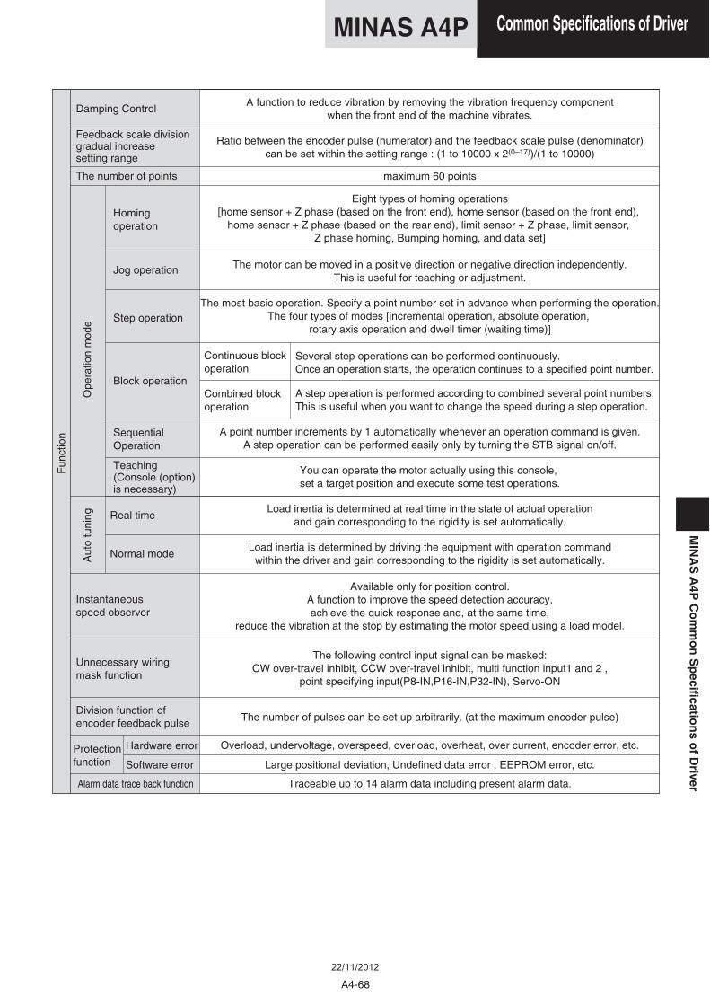
A function to reduce vibration by removing the vibration frequency componentwhen the front end of the machine vibrates.
Ratio between the encoder pulse (numerator) and the feedback scale pulse (denominator)can be set within the setting range : (1 to 10000 x 2(0–17))/(1 to 10000)
maximum 60 points
Eight types of homing operations[home sensor + Z phase (based on the front end), home sensor (based on the front end),
home sensor + Z phase (based on the rear end), limit sensor + Z phase, limit sensor, Z phase homing, Bumping homing, and data set]
The motor can be moved in a positive direction or negative direction independently.This is useful for teaching or adjustment.
A point number increments by 1 automatically whenever an operation command is given.A step operation can be performed easily only by turning the STB signal on/off.
You can operate the motor actually using this console, set a target position and execute some test operations.
Load inertia is determined at real time in the state of actual operationand gain corresponding to the rigidity is set automatically.
Load inertia is determined by driving the equipment with operation commandwithin the driver and gain corresponding to the rigidity is set automatically.
Available only for position control.A function to improve the speed detection accuracy,achieve the quick response and, at the same time,
reduce the vibration at the stop by estimating the motor speed using a load model.
The following control input signal can be masked:CW over-travel inhibit, CCW over-travel inhibit, multi function input1 and 2 ,
point specifying input(P8-IN,P16-IN,P32-IN), Servo-ON
The number of pulses can be set up arbitrarily. (at the maximum encoder pulse)
Overload, undervoltage, overspeed, overload, overheat, over current, encoder error, etc.
Large positional deviation, Undefined data error , EEPROM error, etc.
Traceable up to 14 alarm data including present alarm data.
The most basic operation. Specify a point number set in advance when performing the operation.The four types of modes [incremental operation, absolute operation,
rotary axis operation and dwell timer (waiting time)]
Combined blockoperation
SequentialOperation
Teaching(Console (option)is necessary)
Damping Control
Ope
ratio
n m
ode
Aut
o tu
ning
Several step operations can be performed continuously.Once an operation starts, the operation continues to a specified point number.
A step operation is performed according to combined several point numbers.This is useful when you want to change the speed during a step operation.
A4-68
Common Specifications of DriverMINAS A4PM
INA
SA
4PC
om
mo
nS
pecificatio
ns
of
Driver
22/11/2012
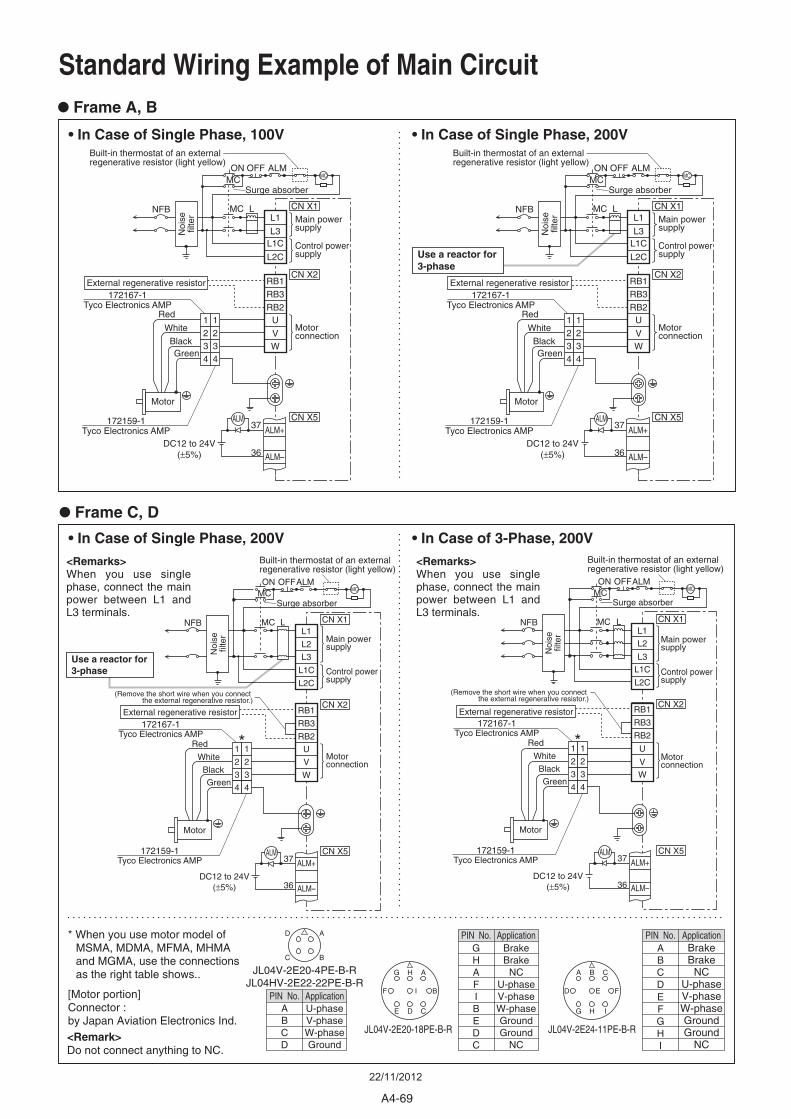
Standard Wiring Example of Main Circuit
• Frame A, B
• Frame C, D
• In Case of Single Phase, 100V • In Case of Single Phase, 200V
• In Case of Single Phase, 200V • In Case of 3-Phase, 200V
AHG
CDE
BIF
CBA
IHG
FED
JL04V-2E20-18PE-B-R JL04V-2E24-11PE-B-R
Noi
sefil
ter Main power
supply
Control powersupply
Motor
ALM37 ALM+
L3L1C
L2C
RB1
MCNFB
RB3RB2
U
VW
L1
CN X2
Surge absorber
External regenerative resistor
ALM–36DC12 to 24V
(±5%)
Red
White
BlackGreen
1234
1234
Motorconnection
CN X5
CN X1
172167-1Tyco Electronics AMP
172159-1Tyco Electronics AMP
L
MCALMON OFF
Use a reactor for3-phase
External regenerative resistor
<Remarks>When you use single phase, connect the main power between L1 and L3 terminals.
Motor
L2
L3
L1C
L2C
RB1
MCNFB
RB3
RB2
U
V
W
L1
Surge absorber
1
2
3
4
1
2
3
4
(Remove the short wire when you connect the external regenerative resistor.)
172167-1Tyco Electronics AMP
172159-1Tyco Electronics AMP
L
<Remarks>When you use single phase, connect the main power between L1 and L3 terminals.
Motor
L2
L3
L1C
L2C
RB1
MCNFB
RB3
RB2
U
VW
L1
Surge absorber
1
2
3
4
1
2
3
4
(Remove the short wire when you connect the external regenerative resistor.)
*172167-1
Tyco Electronics AMP
172159-1Tyco Electronics AMP
L
A
B
D
C
A
JL04V-2E20-4PE-B-RJL04HV-2E22-22PE-B-R
U-phaseV-phaseW-phaseGround
PIN No.
BCD
Application
PIN No. ApplicationGHAFIBEDC
BrakeBrake
NCU-phaseV-phaseW-phaseGroundGround
NC
PIN No. ApplicationA Brake
BrakeNC
U-phaseV-phaseW-phaseGroundGround
NC
BCDEFGHI
<Remark> Do not connect anything to NC.
* When you use motor model of MSMA, MDMA, MFMA, MHMA and MGMA, use the connections as the right table shows..
[Motor portion] Connector : by Japan Aviation Electronics Ind.
CN X2
CN X1
ALM37 ALM+
ALM–36DC12 to 24V
(±5%)
CN X5
CN X2
CN X1
CN X5ALM37 ALM+
ALM–36DC12 to 24V
(±5%)
MCALMON OFF
MCALMON OFF
Use a reactor for3-phase
Noi
sefil
ter
Noi
sefil
terMain power
supply
Control powersupply
Motorconnection
Main powersupply
Control powersupply
Motorconnection
Red
White
Black
Green
External regenerative resistor
Red
White
Black
Green
*
MC
Built-in thermostat of an externalregenerative resistor (light yellow)
MC
Built-in thermostat of an externalregenerative resistor (light yellow)
MC
Built-in thermostat of an externalregenerative resistor (light yellow)
MC
Built-in thermostat of an externalregenerative resistor (light yellow)
A4-69
22/11/2012
Cannon Connector
*
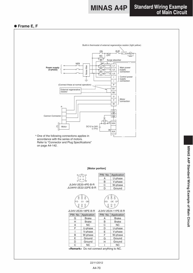
• Frame E, F
Noi
se fi
lter
External regenerative resistor
Main power supplyconnection
Control power supplyconnection
Motor
Surge absorber
Motor connection
Power supply(3-phase)
(Connect these at normal operation)
[Motor portion]
L
ALM37 ALM+
L2
L3
r
t
P
MC
MC
NFB
ALMON
OFF
L1
B2
U
V
W
B1
ALM-
DC12 to 24V(± 5%)
MC
Buiilt-in thermostat of external regenerative resistor (light yellow)
36
PIN No. ApplicationPIN No. Application
A
B
D
C
AHG
CDE
BIF
CBA
IHG
FED
A
JL04V-2E20-4PE-B-RJL04HV-2E22-22PE-B-R
JL04V-2E20-18PE-B-R JL04V-2E24-11PE-B-R
U-phaseV-phaseW-phaseGround
PIN No.
BCD
Application
GHAFIBEDC
BrakeBrake
NCU-phaseV-phaseW-phaseGroundGround
NC
A BrakeBrake
NCU-phaseV-phaseW-phaseGroundGround
NC
BCDEFGHI
<Remark> Do not connect anything to NC.
* One of the following connections applies in accordance with the series of motors. Refer to "Connector and Plug Specifications" on page A4-142.
A4-70
Standard Wiring Example of Main Circuit
MINAS A4PM
INA
SA
4PS
tand
ardW
iring
Exam
ple
of
Main
Circu
it
22/11/2012
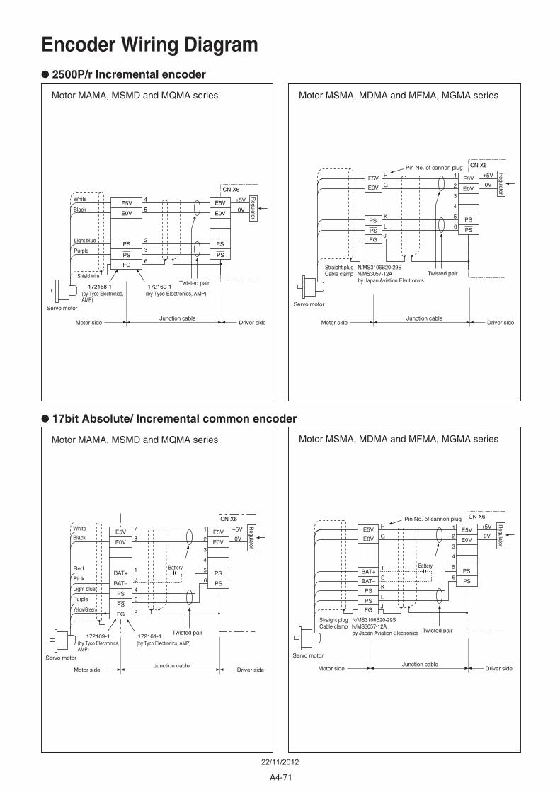
Encoder Wiring Diagram
• 2500P/r Incremental encoder
• 17bit Absolute/ Incremental common encoder
Motor MAMA, MSMD and MQMA series Motor MSMA, MDMA and MFMA, MGMA series
Motor MSMA, MDMA and MFMA, MGMA seriesMotor MAMA, MSMD and MQMA series
Straight plug N/MS3106B20-29SCable clamp N/MS3057-12A
by Japan Aviation Electronics
Straight plug N/MS3106B20-29SCable clamp N/MS3057-12A
by Japan Aviation Electronics
Shield wire
Servo motorServo motor
Servo motor Servo motor
1 +5V
0V
+5V
0V2
3
4
5
6
1 Battery Battery
2
7
8
4
5
3
Twisted pair
Junction cable
(by Tyco Electronics, AMP)172161-1172169-1
(by Tyco Electronics, AMP)
Motor side Driver side
Black
Purple
Yellow/Green
White
Light blue
Pink
Red
Regulator
Regulator
E5V
E0V
E5V
E0V
BAT+
BAT–
PS
PS
1
2
3
4
5
6
H
G
K
L
J
T
S
Twisted pair
Pin No. of cannon plug
Junction cableMotor side Driver side
E5V
E0V
PS
PS
PS
PS
FG
E5V
E0V
PS
PS
BAT+
BAT–
FG
CN X6 CN X6
1 +5V
0V2
3
4
5
6
4
5
2
3
6
Twisted pair
Junction cable
(by Tyco Electronics, AMP)172160-1172168-1
(by Tyco Electronics, AMP)
Motor side Driver side
CN X6
Black
Purple
White
Light blue
E5V
E0V
E5V
E0V
PS
PS
PS
FG
PS
+5V
0V
1
2
3
4
5
6
H
G
K
L
Twisted pair
Pin No. of cannon plug
Junction cableMotor side Driver side
E5V
E0V
PS
PSJ
PS
PS
FG
E5V
E0V
CN X6
Regulator
Regulator
A4-71
22/11/2012
4.7kΩ
4.7kΩ
OA+
OA-
OB+
OB-
OZ+
OZ-
GND
CZ
11
12
13
10
26
16
14
9
330Ω
330Ω
330Ω
COM+
EMG-STP
CCWL
CWL
Z-LS
SRV-ON
P32IN
EX-IN1
EX-IN2
BUSY
P32OUT
P16OUT
P8OUT
P4OUT
P2OUT
P1OUT
COIN/DCLON
ALM
BRK-OFF
COM–
FG
2
1
20
19
23
8
22
29
28
27
15
36
17
18
21
CN X5
STB24
25
VDC
12 to 24V
MAX 50mA
MAX 50mA
34MAX 50mA
33MAX 50mA
32MAX 50mA
31MAX 50mA
30MAX 50mA
MAX 50mA
MAX 50mA
MAX 50mA
4.7kΩ
4.7kΩ
4.7kΩ
4.7kΩ
4.7kΩ
4.7kΩ
P16IN74.7kΩ
P8IN64.7kΩ
P4IN54.7kΩ
P2IN44.7kΩ
P1IN34.7kΩ
4.7kΩ
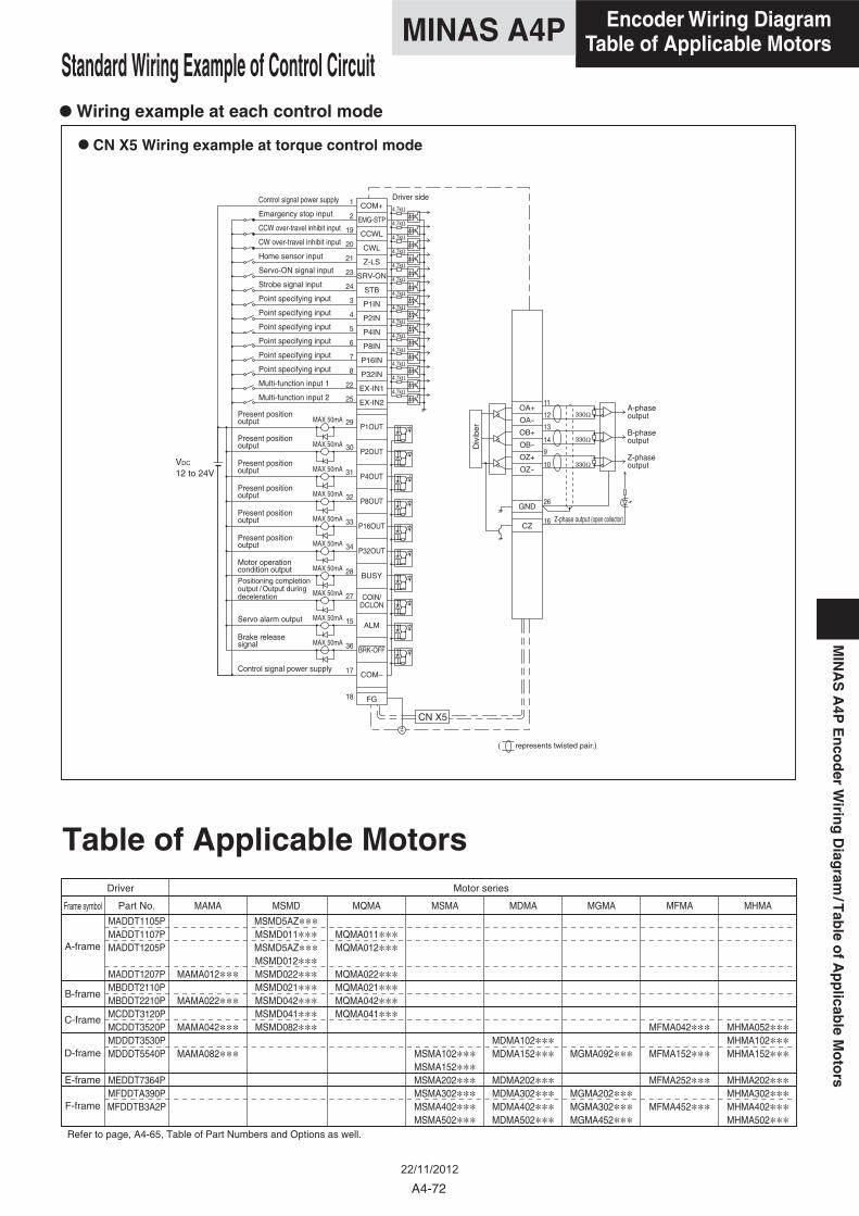
Part No. MADDT1105PMADDT1107PMADDT1205P
MADDT1207PMBDDT2110PMBDDT2210PMCDDT3120PMCDDT3520PMDDDT3530PMDDDT5540P
MEDDT7364PMFDDTA390PMFDDTB3A2P
MAMA
MAMA012***
MAMA022***
MAMA042***
MAMA082***
MSMD
MSMD5AZ***MSMD011***MSMD5AZ***MSMD012***MSMD022***MSMD021***MSMD042***MSMD041***MSMD082***
MQMA
MQMA011***MQMA012***
MQMA022***MQMA021***MQMA042***MQMA041***
MSMA
MSMA102***MSMA152***MSMA202***MSMA302***MSMA402***MSMA502***
MDMA
MDMA102***MDMA152***
MDMA202***MDMA302***MDMA402***MDMA502***
MGMA
MGMA092***
MGMA202***MGMA302***MGMA452***
MFMA
MFMA042***
MFMA152***
MFMA252***
MFMA452***
MHMA
MHMA052***MHMA102***MHMA152***
MHMA202***MHMA302***MHMA402***MHMA502***
A-frame
Driver Motor series
Frame symbol
B-frame
C-frame
D-frame
E-frame
F-frame
Refer to page, A4-65, Table of Part Numbers and Options as well.
Table of Applicable Motors
• CN X5 Wiring example at torque control mode
Control signal power supply
Emargency stop input
CCW over-travel inhibit input
CW over-travel inhibit input
Home sensor input
Servo-ON signal input
Strobe signal input
Point specifying input
Point specifying input
Point specifying input
Point specifying input
Point specifying input
Point specifying input
Multi-function input 1
Multi-function input 2
Present positionoutput
Present positionoutput
Present positionoutput
Present positionoutput
Present positionoutput
Present positionoutput
Motor operationcondition output
Brake releasesignal
A-phaseoutput
B-phaseoutput
Z-phaseoutput
Z-phase output (open collector)
Servo alarm output
Control signal power supply
( represents twisted pair.)
Positioning completionoutput / Output duringdeceleration
Driver side
Div
iber
• Wiring example at each control mode
Standard Wiring Example of Control Circuit
A4-72
Encoder Wiring DiagramTable of Applicable MotorsMINAS A4P
MIN
AS
A4P
En
cod
erW
iring
Diag
ram/T
able
of
Ap
plicab
leM
oto
rs
22/11/2012
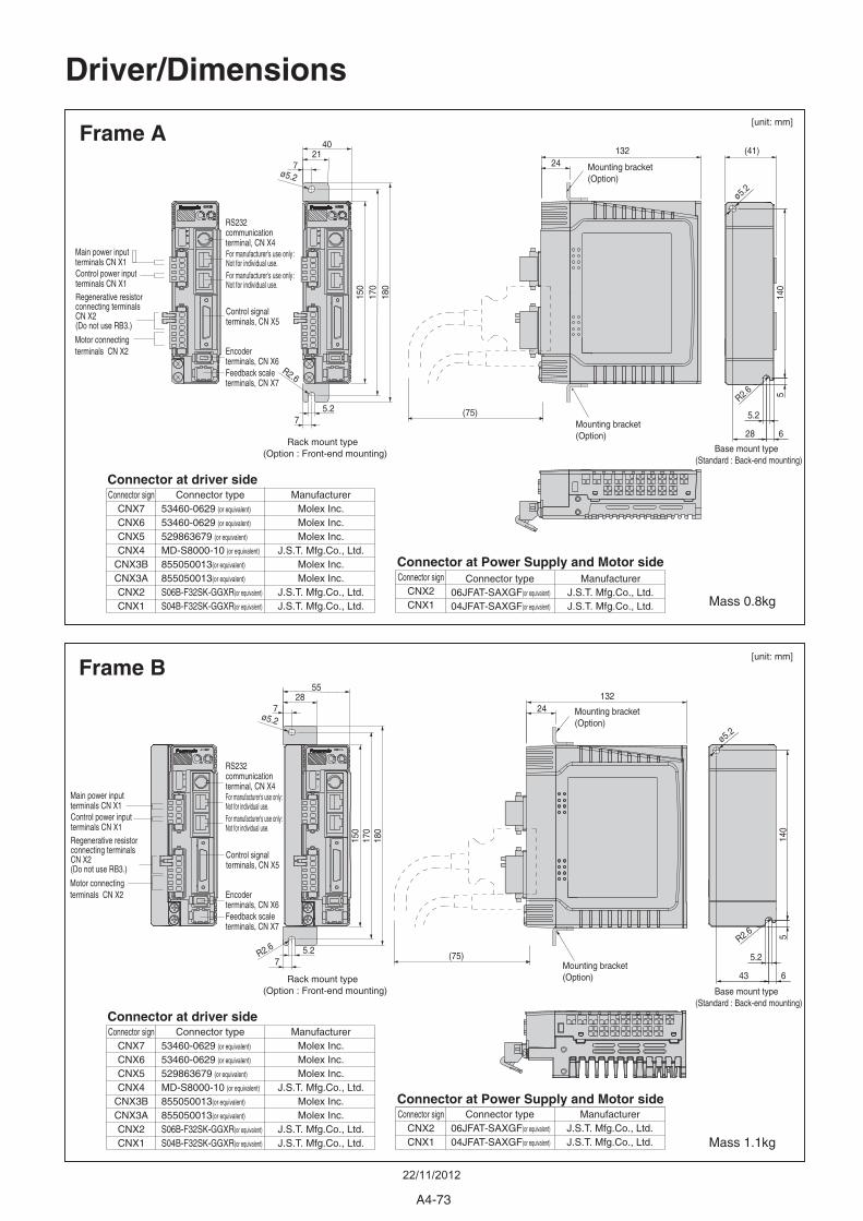
Frame A
Frame B
24
5.2
28 6
132
132 (41)
24
Connector at driver side
Connector at Power Supply and Motor side
R2.6
R2.618
017
015
0
180
170
150
5.27
ø5.2
2140
140
5
7
R2.6 5.27
ø5.2
2855
7
5.2
43 6
R2.6
140
5
ø5.2
ø5.2
(75)
(75)
Connector signCNX7CNX6CNX5CNX4
CNX3BCNX3ACNX2CNX1
ManufacturerMolex Inc.Molex Inc.Molex Inc.
J.S.T. Mfg.Co., Ltd.Molex Inc.Molex Inc.
J.S.T. Mfg.Co., Ltd.J.S.T. Mfg.Co., Ltd.
Connector type53460-0629 (or equivalent)
53460-0629 (or equivalent)
529863679 (or equivalent)
MD-S8000-10 (or equivalent)
855050013(or equivalent)
855050013(or equivalent)
S06B-F32SK-GGXR(or equivalent)
S04B-F32SK-GGXR(or equivalent)
Connector at driver side
Connector signCNX2CNX1
ManufacturerJ.S.T. Mfg.Co., Ltd.J.S.T. Mfg.Co., Ltd.
Connector type06JFAT-SAXGF(or equivalent)
04JFAT-SAXGF(or equivalent)
Connector signCNX7CNX6CNX5CNX4
CNX3BCNX3ACNX2CNX1
ManufacturerMolex Inc.Molex Inc.Molex Inc.
J.S.T. Mfg.Co., Ltd.Molex Inc.Molex Inc.
J.S.T. Mfg.Co., Ltd.J.S.T. Mfg.Co., Ltd.
Connector type53460-0629 (or equivalent)
53460-0629 (or equivalent)
529863679 (or equivalent)
MD-S8000-10 (or equivalent)
855050013(or equivalent)
855050013(or equivalent)
S06B-F32SK-GGXR(or equivalent)
S04B-F32SK-GGXR(or equivalent)
Connector signCNX2CNX1
ManufacturerJ.S.T. Mfg.Co., Ltd.J.S.T. Mfg.Co., Ltd.
Connector type06JFAT-SAXGF(or equivalent)
04JFAT-SAXGF(or equivalent)
Connector at Power Supply and Motor side
Driver/Dimensions
Rack mount type (Option : Front-end mounting)
Rack mount type (Option : Front-end mounting)
Base mount type (Standard : Back-end mounting)
Base mount type (Standard : Back-end mounting)
Mounting bracket(Option)
Mounting bracket(Option)
Mounting bracket(Option)
Mounting bracket(Option)
Mass 0.8kg
Mass 1.1kg
Main power input terminals CN X1
RS232 communicationterminal, CN X4
Control signalterminals, CN X5
For manufacturer's use only :Not for individual use.For manufacturer's use only :Not for individual use.
Encoderterminals, CN X6
Control power input terminals CN X1Regenerative resistor connecting terminals CN X2(Do not use RB3.)
Motor connecting terminals CN X2
Feedback scaleterminals, CN X7
Main power input terminals CN X1
RS232 communicationterminal, CN X4
Control signalterminals, CN X5
Encoderterminals, CN X6
Control power input terminals CN X1Regenerative resistor connecting terminals CN X2(Do not use RB3.)
Motor connecting terminals CN X2
Feedback scaleterminals, CN X7
For manufacturer's use only :Not for individual use.For manufacturer's use only :Not for individual use.
[unit: mm]
[unit: mm]
A4-73
22/11/2012
17224
17224
R2.618
017
015
0
5.2
40
20
ø5.2
4065
20
180
170
150
5.2 5.2
R2.6
10 40
ø5.2
6040
85
10ø5.2
R2.6
5.2
50 7.5
R2.6
140
5
5.2
70 7.5
R2.6
140
5
ø5.2
ø5.2
(75)
(75)
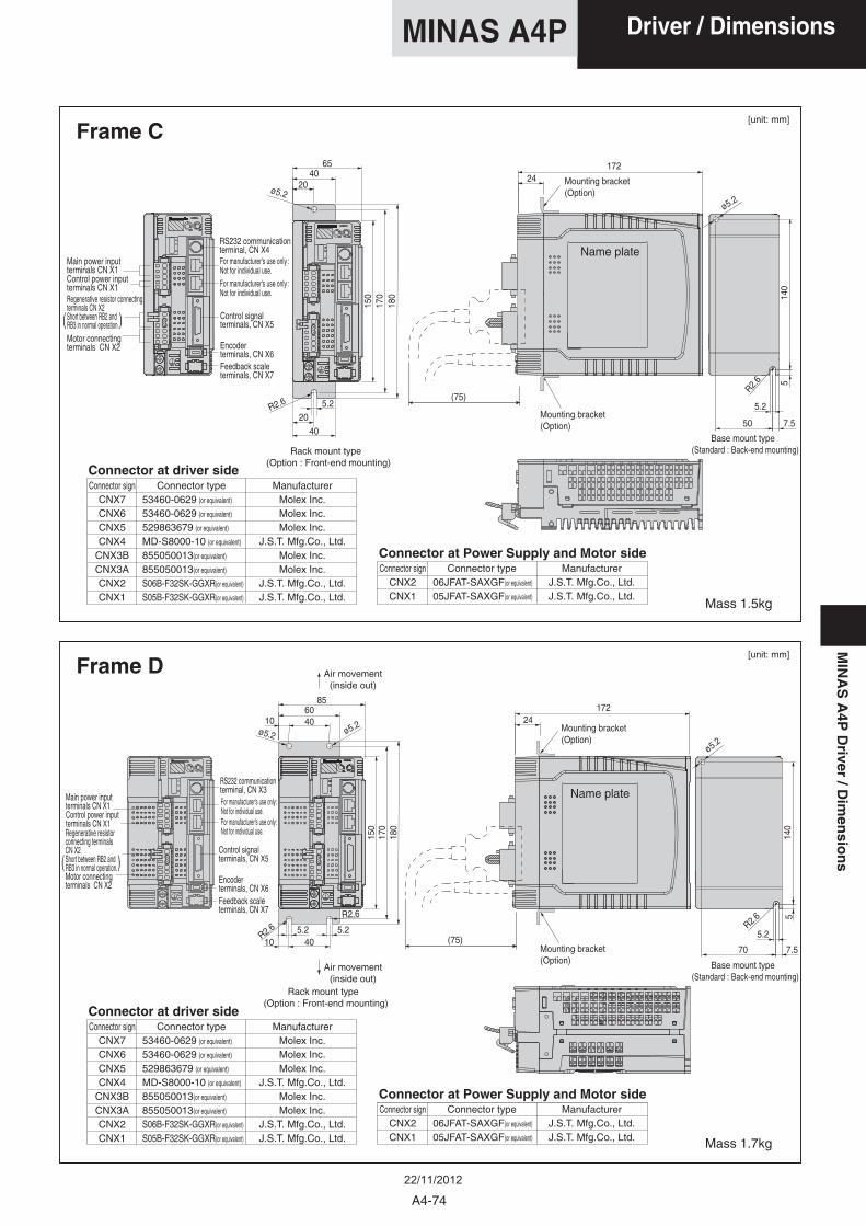
Frame C
Frame D
Mass 1.5kg
Mass 1.7kg
Base mount type (Standard : Back-end mounting)
Mounting bracket(Option)
Mounting bracket(Option)
Mounting bracket(Option)
Base mount type (Standard : Back-end mounting)
Mounting bracket(Option)
Name plate
Name plate
Rack mount type (Option : Front-end mounting)
Air movement(inside out)
Air movement(inside out)
Rack mount type (Option : Front-end mounting)
Main power input terminals CN X1
RS232 communicationterminal, CN X4
Control signalterminals, CN X5
Encoderterminals, CN X6
Control power input terminals CN X1Regenerative resistor connecting terminals CN X2Short between RB2 and RB3 in normal operation.Motor connecting terminals CN X2
Feedback scaleterminals, CN X7
( )
Main power input terminals CN X1Control power input terminals CN X1
Motor connecting terminals CN X2
RS232 communicationterminal, CN X3
Control signalterminals, CN X5
Encoderterminals, CN X6Feedback scaleterminals, CN X7
Regenerative resistor connecting terminals CN X2Short between RB2 and RB3 in normal operation.( )
Connector at driver side
Connector at Power Supply and Motor side
Connector signCNX7CNX6CNX5CNX4
CNX3BCNX3ACNX2CNX1
ManufacturerMolex Inc.Molex Inc.Molex Inc.
J.S.T. Mfg.Co., Ltd.Molex Inc.Molex Inc.
J.S.T. Mfg.Co., Ltd.J.S.T. Mfg.Co., Ltd.
Connector type53460-0629 (or equivalent)
53460-0629 (or equivalent)
529863679 (or equivalent)
MD-S8000-10 (or equivalent)
855050013(or equivalent)
855050013(or equivalent)
S06B-F32SK-GGXR(or equivalent)
S05B-F32SK-GGXR(or equivalent)
Connector at driver side
Connector signCNX2CNX1
ManufacturerJ.S.T. Mfg.Co., Ltd.J.S.T. Mfg.Co., Ltd.
Connector type06JFAT-SAXGF(or equivalent)
05JFAT-SAXGF(or equivalent)
Connector signCNX7CNX6CNX5CNX4
CNX3BCNX3ACNX2CNX1
ManufacturerMolex Inc.Molex Inc.Molex Inc.
J.S.T. Mfg.Co., Ltd.Molex Inc.Molex Inc.
J.S.T. Mfg.Co., Ltd.J.S.T. Mfg.Co., Ltd.
Connector type53460-0629 (or equivalent)
53460-0629 (or equivalent)
529863679 (or equivalent)
MD-S8000-10 (or equivalent)
855050013(or equivalent)
855050013(or equivalent)
S06B-F32SK-GGXR(or equivalent)
S05B-F32SK-GGXR(or equivalent)
Connector signCNX2CNX1
ManufacturerJ.S.T. Mfg.Co., Ltd.J.S.T. Mfg.Co., Ltd.
Connector type06JFAT-SAXGF(or equivalent)
05JFAT-SAXGF(or equivalent)
Connector at Power Supply and Motor side
For manufacturer's use only :Not for individual use.For manufacturer's use only :Not for individual use.
For manufacturer's use only :Not for individual use.For manufacturer's use only :Not for individual use.
[unit: mm]
[unit: mm]
A4-74
Driver / DimensionsMINAS A4PM
INA
SA
4PD
river/D
imen
sion
s
22/11/2012
5.2
ø5.2
50 17.542.5
5.2
ø5.2
50 17.585
42.55.25.2
(88)
188
168
198
32.1(200)
2.6
ø5.2
100 15130
655.25.2
240
220
250
85
5.2
100 1565
5.2 (75)
32.3
(200)
2.6
ø5.2
3.5
3.5
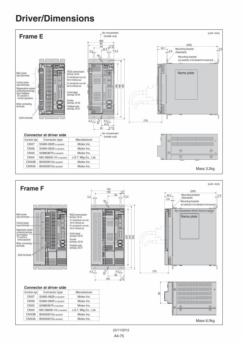
Connector sign
CNX7
CNX6
CNX5
CNX4
CNX3B
CNX3A
Manufacturer
Molex Inc.
Molex Inc.
Molex Inc.
J.S.T. Mfg.Co., Ltd.
Molex Inc.
Molex Inc.
Connector type
53460-0629 (or equivalent)
53460-0629 (or equivalent)
529863679 (or equivalent)
MD-S8000-10 (or equivalent)
855050013(or equivalent)
855050013(or equivalent)
Connector at driver side
Frame E
Frame F
Mass 3.2kg
Mass 6.0kg
Mounting bracket(Standard)
Mounting bracket(Standard)
Main power input terminals
RS232 communicationterminal, CN X4
Control signalterminals, CN X5
Encoderterminals, CN X6
Control power input terminalsRegenerative resistor connecting terminals (short between B1 and B2 in normal operation)
Motor connecting terminals
Earth terminals
Feedback scaleterminals, CN X7
Main power input terminals
RS232 communicationterminal, CN X4
Control signalterminals, CN X5Encoderterminals, CN X6
Control power input terminals
Regenerative resistor connecting terminals (short between B1 and B2 in normal operation)Motor connecting terminals
Earth terminals
Feedback scaleterminals, CN X7
Air movement(inside out)
Air movement(inside out)
Air movement (from front to back)
Driver/Dimensions
Mounting bracket(put substitution of the Standard for the back-end)
Mounting bracket(put substitution of the Standard for the back-end)
Name plate
Name plate
(75)
For manufacturer's use only :Not for individual use.For manufacturer's use only :Not for individual use.
For manufacturer's use only :Not for individual use.For manufacturer's use only :Not for individual use.
[unit: mm]
[unit: mm]
A4-75
22/11/2012
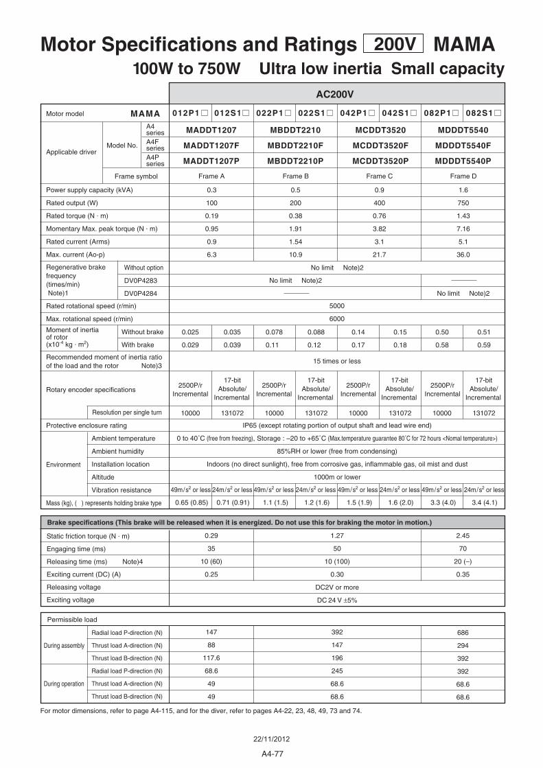
Motor Specifications and Ratings 200V MAMA100W to 750W Ultra low inertia Small capacity
AC200V
012P1 012S1 022P1 022S1 042P1 042S1 082P1 082S1
MCDDT3520MBDDT2210MADDT1207 MDDDT5540
MCDDT3520FMBDDT2210FMADDT1207F MDDDT5540F
MCDDT3520PMBDDT2210PMADDT1207P MDDDT5540P
For motor dimensions, refer to page A4-115, and for the diver, refer to pages A4-22, 23, 48, 49, 73 and 74.
During assembly
During operation
Environment
Radial load P-direction (N)
Thrust load A-direction (N)
Thrust load B-direction (N)
Radial load P-direction (N)
Thrust load A-direction (N)
Thrust load B-direction (N)
Permissible load
Brake specifications (This brake will be released when it is energized. Do not use this for braking the motor in motion.)
Static friction torque (N . m)
Engaging time (ms)
Releasing time (ms) Note)4
Exciting current (DC) (A)
Releasing voltage
Exciting voltage
0.3
100
0.19
0.95
0.9
6.3
0.025
0.029
2500P/r Incremental
2500P/r Incremental
2500P/r Incremental
2500P/r Incremental
17-bit Absolute/
Incremental
17-bit Absolute/
Incremental
17-bit Absolute/
Incremental
17-bit Absolute/
Incremental
0.078
0.11
0.14
0.17
0.50
0.58
0.035
0.039
0.088
0.12
0.15
0.18
0.51
0.59
0.5
200
0.38
1.91
1.54
10.9
No limit Note)2
0.9
400
0.76
3.82
3.1
21.7
1.6
750
1.43
7.16
5.1
36.0
No limit Note)2
Protective enclosure rating
Ambient temperature
Ambient humidity
Installation location
Altitude
Vibration resistance
Mass (kg), ( ) represents holding brake type
Rated rotational speed (r/min)
Max. rotational speed (r/min)
Power supply capacity (kVA)
Rated output (W)
Rated torque (N . m)
Momentary Max. peak torque (N . m)
Rated current (Arms)
Max. current (Ao-p)
Motor model
Applicable driverModel No.
Frame symbol
Resolution per single turn
Rotary encoder specifications
Moment of inertiaof rotor(x10-4 kg . m2)
Recommended moment of inertia ratioof the load and the rotor Note)3
Without brake
With brake
Regenerative brakefrequency (times/min) Note)1
Without option
DV0P4283
DV0P4284
MAMA
5000
6000
Frame CFrame BFrame A Frame D
15 times or less
10000 131072 10000 131072
IP65 (except rotating portion of output shaft and lead wire end)
0 to 40˚C (free from freezing), Storage : –20 to +65˚C (Max.temperature guarantee 80˚C for 72 hours <Nomal temperature>)
85%RH or lower (free from condensing)
Indoors (no direct sunlight), free from corrosive gas, inflammable gas, oil mist and dust
1000m or lower
10000 131072 10000
0.65 (0.85) 0.71 (0.91) 1.1 (1.5) 1.2 (1.6) 1.5 (1.9) 1.6 (2.0) 3.3 (4.0) 3.4 (4.1)
0.29
35
10 (60)
0.25
1.27
50
10 (100)
0.30
DC2V or more
DC 24 V ±5%
2.45
70
20 (–)
0.35
147
88
117.6
68.6
49
49
392
147
196
245
68.6
68.6
686
294
392
392
68.6
68.6
131072
49m/s2 or less 24m/s2 or less 24m/s2 or less 24m/s2 or less 24m/s2 or less49m/s2 or less 49m/s2 or less 49m/s2 or less
No limit Note)2
A4seriesA4FseriesA4Pseries
A4-77
22/11/2012

M A M A 0 1 2 S 1 A
Note) 1. Regenerative brake frequency represents the frequency of the motor's stops from the rated speed with deceleration without load. . If the load is connected, frequency will be defines as 1/(m+1), where m=load moment of inertia/rotor moment of inertia. . When the motor speed exceeds the rated speed, regenerative brake frequency is in inverse proportion to the square of (running speed/rated speed). . Power supply voltage is AC230V (at 200V of the main voltage). If the supply voltage fluctuates, frequency is in inverse proportion to the square of (Running supply voltage/230) relative to the value in the table. . When regeneration occurs continuously such cases as running speed frequently changes or vertical feeding, consult us or a dealer. 2. If the effective torque is within the rated torque, there is no limit in generative brake. 3. Consult us or a dealer if the load moment of inertia exceeds the specified value. 4. Specified releasing time is obtained with the use of surge absorber for brake (Z15D151 by Ishizuka Electronic or equivalent). ( ) represents the actually measured value using a diode (200V, 1A or equivalent)
A
B
Thrust load (A, B) direction
Radial load (P) directionL
L/2P
Model designation
Torque characteristics at AC200V of power voltage
MAMA series, 100W to 750W
e.g.)
Symbol
P
S
Symbol
MAMA
Type
Ultra low inertia(100W-750W)
Format
Incremental
Absolute/Incremental
Pulse counts
2500P/r
17-bit
Resolution
10000
131072
Wires
5
7
Symbol
01
02
04
08
Rated output
100W
200W
400W
750W
Rotary encoder specifications
Motor rated output
Symbol
2
Specifications
200V
Voltage specificationsMotor structureDesign order
1 : StandardSymbol
A
B
E
F
Shaft
withoutRound withKey-way without with
Holding brake Oil seal
torque[N . m]
rotational speed [r/min]
Peak run range
ambient temperature[˚C]
*Continuous torque, ambient temperature
vers
us r
ated
torq
ue (
%)
MAMA012 1 MAMA022 1
MAMA042 1 MAMA082 1
0.5
(0.19)
(5000)
(0.95)
0 2000 4000 6000
1.0
0 10 20 30 40
100
501.0
(0.38)
(5000)
(1.91)
0 2000 4000 6000
2.0
0 10 20 30 40
100
50
4.0
(1.43)
(5000)
(7.16)
0 2000 4000 6000
8.0
0 10 20 30 40
100
502.0
(0.76)
(5000)
(3.82)
0 2000 4000 6000
4.0
0 10 20 30 40
100
50
*When you lower the torque limit setup (Pr5E and 5F), running range at high speed might be lowered as well.
Torque
rotational speed
Continuous running range
Running range (Torque limit setup : 300%)
Running range (Torque limit setup : 200%)
Running range (Torque limit setup : 100%)
Shaft
Motor
Continuous run range
torque[N . m]
rotational speed [r/min]
Peak run range
ambient temperature[˚C]
*Continuous torque, ambient temperature
vers
us r
ated
torq
ue (
%)
Continuous run range
torque[N . m]
torque[N . m]
rotational speed [r/min]
rotational speed [r/min]
Peak run range
Peak run range
ambient temperature[˚C]
ambient temperature[˚C]
*Continuous torque, ambient temperature
*Continuous torque, ambient temperature
vers
us r
ated
torq
ue (
%)
vers
us r
ated
torq
ue (
%)
Continuous run range
Continuous run range
A4-78
MAMA100W-750W
A4MINAS A4FA4P
MIN
AS
A4/A
4F/A
4PM
oto
r
22/11/2012
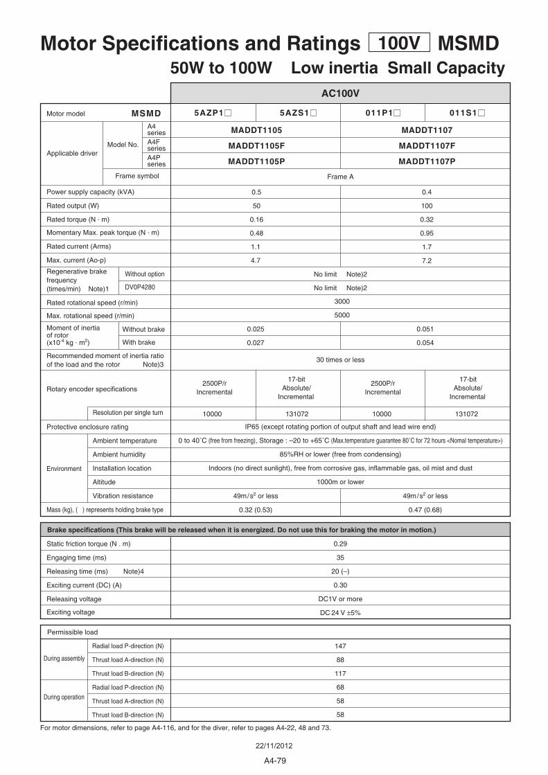
Motor Specifications and Ratings 100V MSMD50W to 100W Low inertia Small Capacity
5AZP1 5AZS1 011P1 011S1
0.025
0.027
0.051
0.054
0.5 0.4
100
0.32
0.95
1.7
7.2
50
0.16
0.48
MSMD
3000
5000
10000 131072 10000 131072
0.29
35
20 (–)
0.30
DC1V or more
DC 24 V ±5%
147
88
117
68
58
58
0.32 (0.53) 0.47 (0.68)
MADDT1105 MADDT1107
MADDT1105P MADDT1107P
Without option
DV0P4280
Frame A
1.1
4.7
AC100V
For motor dimensions, refer to page A4-116, and for the diver, refer to pages A4-22, 48 and 73.
During assembly
During operation
Environment
Radial load P-direction (N)
Thrust load A-direction (N)
Thrust load B-direction (N)
Radial load P-direction (N)
Thrust load A-direction (N)
Thrust load B-direction (N)
Permissible load
Brake specifications (This brake will be released when it is energized. Do not use this for braking the motor in motion.)
Static friction torque (N . m)
Engaging time (ms)
Releasing time (ms) Note)4
Exciting current (DC) (A)
Releasing voltage
Exciting voltage
2500P/r Incremental
2500P/r Incremental
17-bit Absolute/
Incremental
17-bit Absolute/
Incremental
Protective enclosure rating
Ambient temperature
Ambient humidity
Installation location
Altitude
Vibration resistance
Mass (kg), ( ) represents holding brake type
Rated rotational speed (r/min)
Max. rotational speed (r/min)
Power supply capacity (kVA)
Rated output (W)
Rated torque (N . m)
Momentary Max. peak torque (N . m)
Rated current (Arms)
Max. current (Ao-p)
Motor model
Applicable driver
Resolution per single turn
Rotary encoder specifications
Moment of inertiaof rotor(x10-4 kg . m2)
Recommended moment of inertia ratioof the load and the rotor Note)3
Without brake
With brake
Regenerative brakefrequency (times/min) Note)1
30 times or less
IP65 (except rotating portion of output shaft and lead wire end)
0 to 40˚C (free from freezing), Storage : –20 to +65˚C (Max.temperature guarantee 80˚C for 72 hours <Nomal temperature>)
85%RH or lower (free from condensing)
Indoors (no direct sunlight), free from corrosive gas, inflammable gas, oil mist and dust
1000m or lower
49m/s2 or less 49m/s2 or less
No limit Note)2
No limit Note)2
Model No.
Frame symbol
A4series
MADDT1105F MADDT1107FA4FseriesA4Pseries
A4-79
22/11/2012
Motor structure
M S M D 5 A Z S 1 S
Wit
ho
ut
Oil
seal
Wit
h O
il se
al
Wit
h O
il se
alW
ith
ou
t O
il se
al
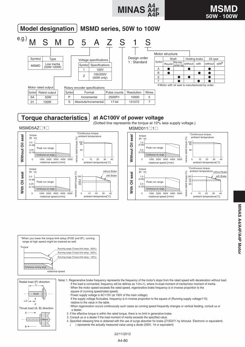
(Dotted line represents the torque at 10% less supply voltage.)
Note) 1. Regenerative brake frequency represents the frequency of the motor's stops from the rated speed with deceleration without load. . If the load is connected, frequency will be defines as 1/(m+1), where m=load moment of inertia/rotor moment of inertia. . When the motor speed exceeds the rated speed, regenerative brake frequency is in inverse proportion to the square of (running speed/rated speed). . Power supply voltage is AC115V (at 100V of the main voltage). If the supply voltage fluctuates, frequency is in inverse proportion to the square of (Running supply voltage/115) relative to the value in the table. . When regeneration occurs continuously such cases as running speed frequently changes or vertical feeding, consult us or a dealer. 2. If the effective torque is within the rated torque, there is no limit in generative brake. 3. Consult us or a dealer if the load moment of inertia exceeds the specified value. 4. Specified releasing time is obtained with the use of surge absorber for brake (Z15D271 by Ishizuka Electronic or equivalent). ( ) represents the actually measured value using a diode (200V, 1A or equivalent)
Model designation
Torque characteristics at AC100V of power voltage
MSMD series, 50W to 100W
e.g.)
Symbol
P
S
Symbol
MSMD
Type
Low inertia(50W-100W)
Format
Incremental
Absolute/Incremental
Pulse counts
2500P/r
17-bit
Resolution
10000
131072
Wires
5
7
Symbol
5A
01
Rated output
50W
100W
Rotary encoder specificationsMotor rated output
Symbol
1
Z
Specifications
100V
100/200V(50W only)
Voltage specificationsDesign order1 : Standard
MSMD5AZ 1
0.25
0 1000 2000 3000 4000 5000
0.5 95
50
0 10 20 30 40
100
MSMD011 1
95
50
0 10 20 30 40
100
0.5
0 1000 2000 3000 4000 5000
1.0
0.5
0 1000 2000 3000 4000 5000
1.0757050
0 10 20 30 40
100
0.25
0 1000 2000 3000 4000 5000
0.5
706050
0 10 20 30 40
100
(0.48) (0.95)
(0.32)
(0.95)
(0.32)
(0.16)
(0.48)
(0.16)
with Brake
without Brake
torque[N . m]
torque[N . m]
rotational speed [r/min]
rotational speed [r/min]
Peak run range
Peak run range
ambient temperature[˚C]
ambient temperature[˚C]
*Continuous torque, ambient temperature
vers
us r
ated
torq
ue (
%)
vers
us r
ated
torq
ue (
%)
Continuous run range
Continuous run range
with Brake
without Brake
torque[N . m]
torque[N . m]
rotational speed [r/min]
rotational speed [r/min]
Peak run range
Peak run range
ambient temperature[˚C]
ambient temperature[˚C]
*Continuous torque, ambient temperature
*Continuous torque, ambient temperature
vers
us r
ated
torq
ue (
%)
vers
us r
ated
torq
ue (
%)
Continuous run range
Continuous run range
A
B
Thrust load (A, B) direction
Radial load (P) directionL
L/2P
Shaft
Motor
*When you lower the torque limit setup (Pr5E and 5F), running range at high speed might be lowered as well.
Torque
rotational speed
Continuous running range
Running range (Torque limit setup : 300%)
Running range (Torque limit setup : 200%)
Running range (Torque limit setup : 100%)
A
B
Symbol
ST
without with withwithout
Shaft Holding brake Oil sealKey-way, center tap Round
Motor with oil seal is manufactured by order.
MIN
AS
A4/A
4F/A
4PM
oto
r
A4-80
MSMD50W - 100W
A4MINAS A4FA4P
22/11/2012
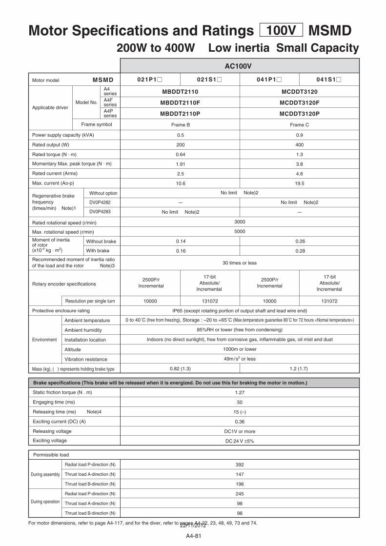
021P1 021S1 041P1 041S1
MBDDT2110 MCDDT3120
MBDDT2110P MCDDT3120P
0.14
0.16
0.26
0.28
0.5
200
0.64
1.91
2.5
10.6
0.9
400
1.3
3.8
4.6
19.5
Without option
DV0P4282
DV0P4283
MSMD
3000
5000
10000 131072 10000 131072
0.82 (1.3) 1.2 (1.7)
1.27
50
15 (–)
0.36
DC1V or more
DC 24 V ±5%
392
147
196
245
98
98
–
–
Frame B Frame C
Motor Specifications and Ratings 100V MSMD200W to 400W Low inertia Small Capacity
AC100V
For motor dimensions, refer to page A4-117, and for the diver, refer to pages A4-22, 23, 48, 49, 73 and 74.
During assembly
During operation
Environment
Radial load P-direction (N)
Thrust load A-direction (N)
Thrust load B-direction (N)
Radial load P-direction (N)
Thrust load A-direction (N)
Thrust load B-direction (N)
Permissible load
Brake specifications (This brake will be released when it is energized. Do not use this for braking the motor in motion.)
Static friction torque (N . m)
Engaging time (ms)
Releasing time (ms) Note)4
Exciting current (DC) (A)
Releasing voltage
Exciting voltage
2500P/r Incremental
2500P/r Incremental
17-bit Absolute/
Incremental
17-bit Absolute/
Incremental
Protective enclosure rating
Ambient temperature
Ambient humidity
Installation location
Altitude
Vibration resistance
Mass (kg), ( ) represents holding brake type
Rated rotational speed (r/min)
Max. rotational speed (r/min)
Power supply capacity (kVA)
Rated output (W)
Rated torque (N . m)
Momentary Max. peak torque (N . m)
Rated current (Arms)
Max. current (Ao-p)
Motor model
Applicable driver
Resolution per single turn
Rotary encoder specifications
Moment of inertiaof rotor(x10-4 kg . m2)
Recommended moment of inertia ratioof the load and the rotor Note)3
Without brake
With brake
Regenerative brakefrequency (times/min) Note)1
30 times or less
IP65 (except rotating portion of output shaft and lead wire end)
0 to 40˚C (free from freezing), Storage : –20 to +65˚C (Max.temperature guarantee 80˚C for 72 hours <Nomal temperature>)
85%RH or lower (free from condensing)
Indoors (no direct sunlight), free from corrosive gas, inflammable gas, oil mist and dust
1000m or lower
49m/s2 or less
No limit Note)2
No limit Note)2
No limit Note)2
Model No.
Frame symbol
A4series
A4Pseries
MBDDT2110F MCDDT3120FA4Fseries
A4-81
22/11/2012
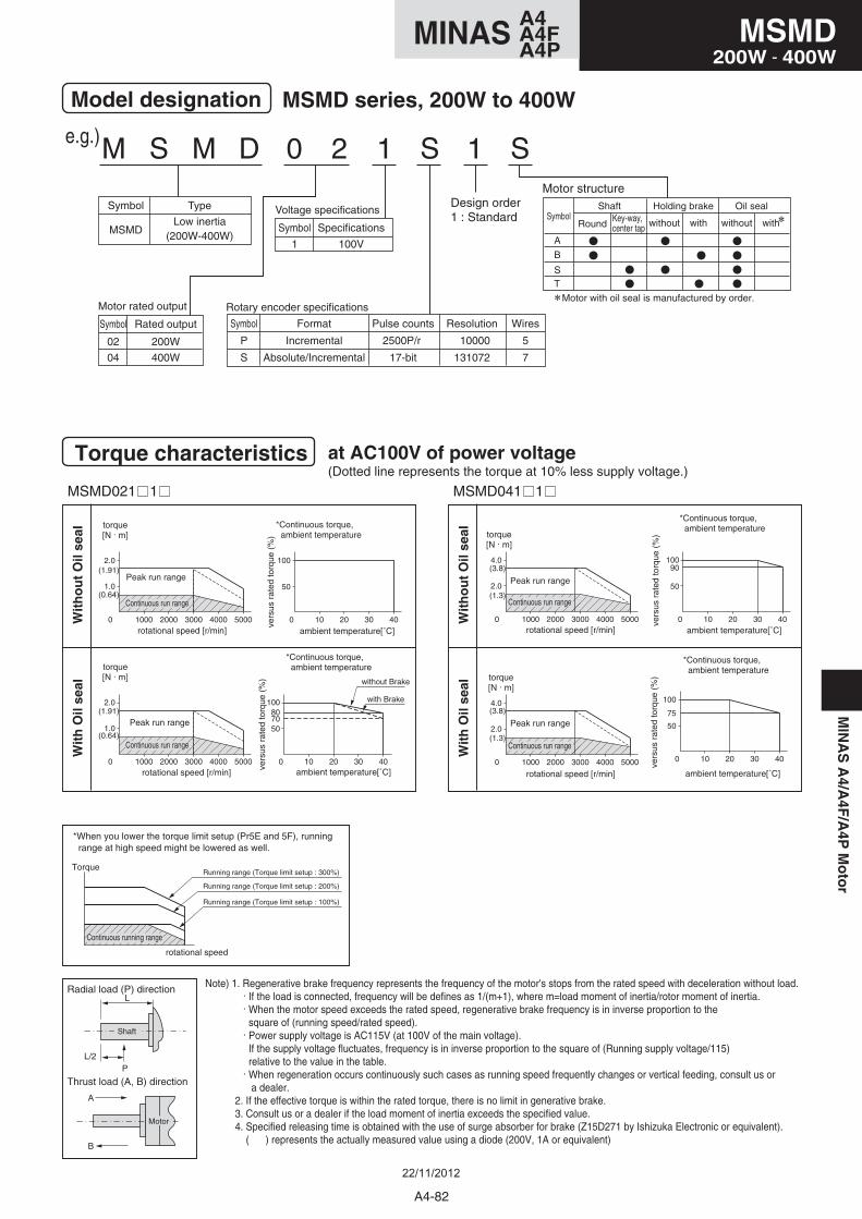
Motor structure
M S M D 0 2 1 S 1 S
Wit
ho
ut
Oil
seal
Wit
h O
il se
al
Wit
ho
ut
Oil
seal
Wit
h O
il se
al(Dotted line represents the torque at 10% less supply voltage.)
Model designation
Torque characteristics at AC100V of power voltage
MSMD series, 200W to 400W
e.g.)
Symbol
P
S
Symbol
MSMD
Type
Low inertia(200W-400W)
Format
Incremental
Absolute/Incremental
Pulse counts
2500P/r
17-bit
Resolution
10000
131072
Wires
5
7
Symbol
02
04
Rated output
200W
400W
Rotary encoder specificationsMotor rated output
Symbol
1
Specifications
100V
Voltage specificationsDesign order1 : Standard
MSMD021 1 MSMD041 1
2.0
0 1000 2000 3000 4000 5000
4.090
50
0 10 20 30 40
100
2.0
0 1000 2000 3000 4000 5000
4.075
50
0 10 20 30 40
100
807050
0 10 20 30 40
100
1.0
0 1000 2000 3000 4000 5000
2.0
1.0
0 1000 2000 3000 4000 5000
2.0
50
0 10 20 30 40
100(1.91)
(0.64)
(1.91)
(0.64)
(3.8)
(1.3)
(3.8)
(1.3)
with Brake
without Brake
torque[N . m]
torque[N . m]
rotational speed [r/min]
rotational speed [r/min]
Peak run range
Peak run range
ambient temperature[˚C]
ambient temperature[˚C]
*Continuous torque, ambient temperature
*Continuous torque, ambient temperature
vers
us r
ated
torq
ue (
%)
vers
us r
ated
torq
ue (
%)
Continuous run range
Continuous run range
torque[N . m]
torque[N . m]
rotational speed [r/min]
rotational speed [r/min]
Peak run range
Peak run range
ambient temperature[˚C]
ambient temperature[˚C]
*Continuous torque, ambient temperature
*Continuous torque, ambient temperature
vers
us r
ated
torq
ue (
%)
vers
us r
ated
torq
ue (
%)
Continuous run range
Continuous run range
Note) 1. Regenerative brake frequency represents the frequency of the motor's stops from the rated speed with deceleration without load. . If the load is connected, frequency will be defines as 1/(m+1), where m=load moment of inertia/rotor moment of inertia. . When the motor speed exceeds the rated speed, regenerative brake frequency is in inverse proportion to the square of (running speed/rated speed). . Power supply voltage is AC115V (at 100V of the main voltage). If the supply voltage fluctuates, frequency is in inverse proportion to the square of (Running supply voltage/115) relative to the value in the table. . When regeneration occurs continuously such cases as running speed frequently changes or vertical feeding, consult us or a dealer. 2. If the effective torque is within the rated torque, there is no limit in generative brake. 3. Consult us or a dealer if the load moment of inertia exceeds the specified value. 4. Specified releasing time is obtained with the use of surge absorber for brake (Z15D271 by Ishizuka Electronic or equivalent). ( ) represents the actually measured value using a diode (200V, 1A or equivalent)
A
B
Thrust load (A, B) direction
Radial load (P) directionL
L/2P
Shaft
Motor
*When you lower the torque limit setup (Pr5E and 5F), running range at high speed might be lowered as well.
Torque
rotational speed
Continuous running range
Running range (Torque limit setup : 300%)
Running range (Torque limit setup : 200%)
Running range (Torque limit setup : 100%)
A
B
Symbol
ST
without with withwithout
Shaft Holding brake Oil sealKey-way, center tap Round
Motor with oil seal is manufactured by order.
MIN
AS
A4/A
4F/A
4PM
oto
rA4MINAS A4FA4P
MSMD200W - 400W
A4MINAS A4FA4P
A4-82
22/11/2012
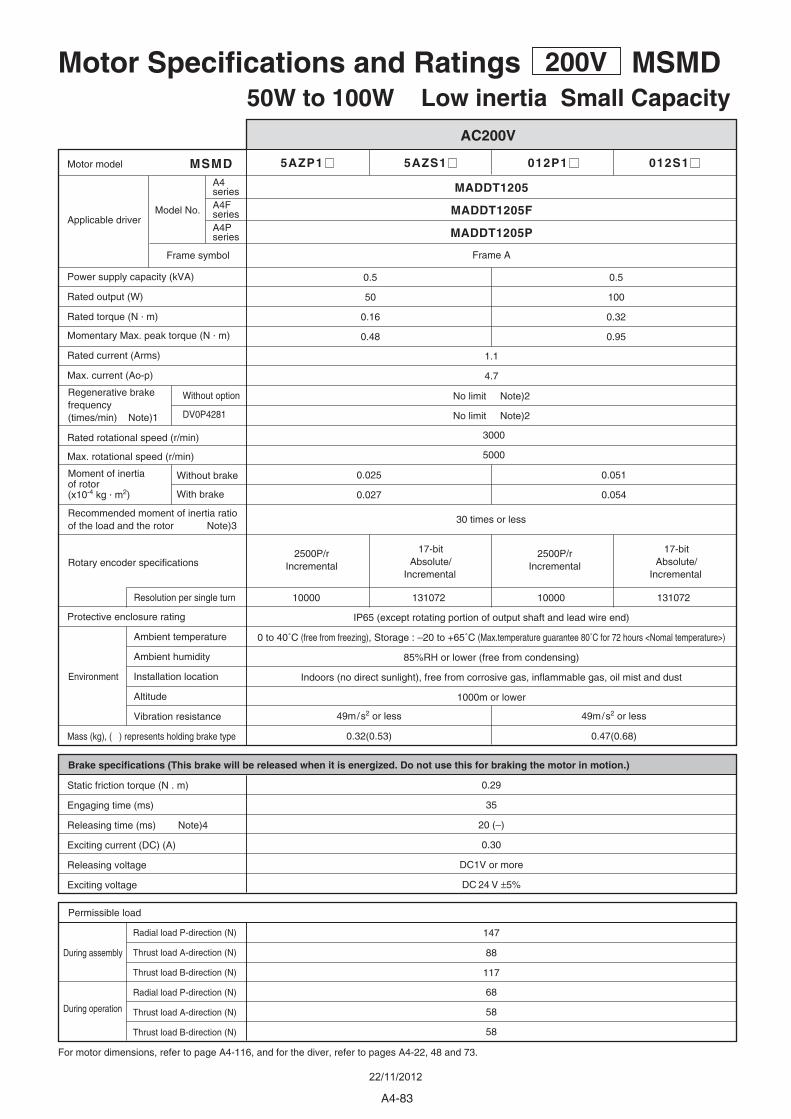
5AZP1 5AZS1 012P1 012S1
0.025
0.027
0.051
0.054
1.1
4.7
0.5 0.5
100
0.32
0.95
50
0.16
0.48
MSMD
3000
5000
30 times or less
10000 131072 10000 131072
0.29
35
20 (–)
0.30
DC1V or more
DC 24 V ±5%
147
88
117
68
58
58
0.32(0.53)
49m/s2 or less
0.47(0.68)
49m/s2 or less
MADDT1205
MADDT1205P
Without option
DV0P4281
Frame A
Motor Specifications and Ratings 200V MSMD50W to 100W Low inertia Small Capacity
AC200V
For motor dimensions, refer to page A4-116, and for the diver, refer to pages A4-22, 48 and 73.
During assembly
During operation
Environment
Radial load P-direction (N)
Thrust load A-direction (N)
Thrust load B-direction (N)
Radial load P-direction (N)
Thrust load A-direction (N)
Thrust load B-direction (N)
Permissible load
Brake specifications (This brake will be released when it is energized. Do not use this for braking the motor in motion.)
Static friction torque (N . m)
Engaging time (ms)
Releasing time (ms) Note)4
Exciting current (DC) (A)
Releasing voltage
Exciting voltage
2500P/r Incremental
2500P/r Incremental
17-bit Absolute/
Incremental
17-bit Absolute/
Incremental
Protective enclosure rating
Ambient temperature
Ambient humidity
Installation location
Altitude
Vibration resistance
Mass (kg), ( ) represents holding brake type
Rated rotational speed (r/min)
Max. rotational speed (r/min)
Power supply capacity (kVA)
Rated output (W)
Rated torque (N . m)
Momentary Max. peak torque (N . m)
Rated current (Arms)
Max. current (Ao-p)
Motor model
Applicable driver
Resolution per single turn
Rotary encoder specifications
Moment of inertiaof rotor(x10-4 kg . m2)
Recommended moment of inertia ratioof the load and the rotor Note)3
Without brake
With brake
Regenerative brakefrequency (times/min) Note)1
IP65 (except rotating portion of output shaft and lead wire end)
0 to 40˚C (free from freezing), Storage : –20 to +65˚C (Max.temperature guarantee 80˚C for 72 hours <Nomal temperature>)
85%RH or lower (free from condensing)
Indoors (no direct sunlight), free from corrosive gas, inflammable gas, oil mist and dust
1000m or lower
No limit Note)2
No limit Note)2
Model No.
Frame symbol
A4series
MADDT1205FA4FseriesA4Pseries
A4-83
22/11/2012
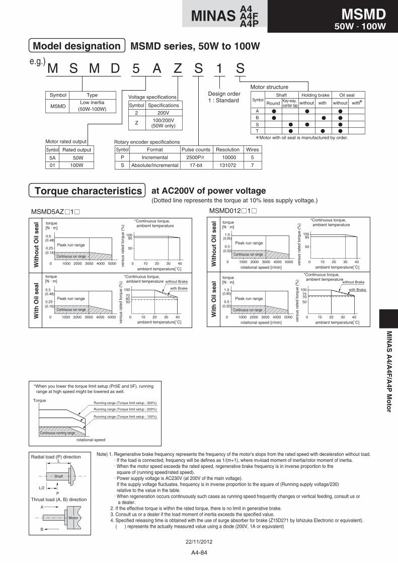
Motor structure
M S M D 5 A Z S 1 S
Wit
ho
ut
Oil
seal
Wit
h O
il se
al
Note) 1. Regenerative brake frequency represents the frequency of the motor's stops from the rated speed with deceleration without load. . If the load is connected, frequency will be defines as 1/(m+1), where m=load moment of inertia/rotor moment of inertia. . When the motor speed exceeds the rated speed, regenerative brake frequency is in inverse proportion to the square of (running speed/rated speed). . Power supply voltage is AC230V (at 200V of the main voltage). If the supply voltage fluctuates, frequency is in inverse proportion to the square of (Running supply voltage/230) relative to the value in the table. . When regeneration occurs continuously such cases as running speed frequently changes or vertical feeding, consult us or a dealer. 2. If the effective torque is within the rated torque, there is no limit in generative brake. 3. Consult us or a dealer if the load moment of inertia exceeds the specified value. 4. Specified releasing time is obtained with the use of surge absorber for brake (Z15D271 by Ishizuka Electronic or equivalent). ( ) represents the actually measured value using a diode (200V, 1A or equivalent)
Model designation
Torque characteristics at AC200V of power voltage
MSMD series, 50W to 100We.g.)
Symbol
P
S
Symbol
MSMD
Type
Low inertia(50W-100W)
Format
Incremental
Absolute/Incremental
Pulse counts
2500P/r
17-bit
Resolution
10000
131072
Wires
5
7
Symbol
5A
01
Rated output
50W
100W
Rotary encoder specificationsMotor rated output
Symbol
2
Z
Specifications
200V
100/200V(50W only)
Voltage specificationsDesign order1 : Standard
MSMD5AZ 1
0.25
0 1000 2000 3000 4000 5000
0.5 95
50
0 10 20 30 40
100
0.25
0 1000 2000 3000 4000 5000
0.5
706050
0 10 20 30 40
100
MSMD012 1
0.5
0 1000 2000 3000 4000 5000
1.095
50
0 10 20 30 40
100
757050
0 10 20 30 40
100
0.5
0 1000 2000 3000 4000 5000
1.0
(0.48) (0.95)
(0.32)
(0.95)
(0.32)
(0.16)
(0.48)
(0.16)
with Brake
without Brake
torque[N . m]
torque[N . m]
Peak run range
Peak run range
ambient temperature[˚C]
ambient temperature[˚C]
*Continuous torque, ambient temperature
*Continuous torque, ambient temperature
vers
us r
ated
torq
ue (
%)
vers
us r
ated
torq
ue (
%)
Continuous run range
Continuous run range
Wit
ho
ut
Oil
seal
Wit
h O
il se
al
with Brake
without Brake
torque[N . m]
torque[N . m]
rotational speed [r/min]
rotational speed [r/min]
Peak run range
Peak run range
ambient temperature[˚C]
ambient temperature[˚C]
*Continuous torque, ambient temperature
*Continuous torque, ambient temperature
vers
us r
ated
torq
ue (
%)
vers
us r
ated
torq
ue (
%)
Continuous run range
Continuous run range
A
B
Thrust load (A, B) direction
Radial load (P) directionL
L/2P
Shaft
Motor
*When you lower the torque limit setup (Pr5E and 5F), running range at high speed might be lowered as well.
Torque
rotational speed
Continuous running range
Running range (Torque limit setup : 300%)
Running range (Torque limit setup : 200%)
Running range (Torque limit setup : 100%)
A
B
Symbol
ST
without with withwithout
Shaft Holding brake Oil sealKey-way, center tap Round
Motor with oil seal is manufactured by order.
(Dotted line represents the torque at 10% less supply voltage.)
MIN
AS
A4/A
4F/A
4PM
oto
rMSMD
50W - 100W
A4-84
A4MINAS A4FA4P
22/11/2012

022P1 022S1 042P1 042S1 082P1 082S1
MADDT1207 MCDDT3520MBDDT2210
MADDT1207P MCDDT3520PMBDDT2210P
0.5
200
0.64
1.91
1.6
6.9
0.87
0.97
0.26
0.28
0.14
0.16
0.9
400
1.3
3.8
2.6
11.0
1.3
750
2.4
7.1
4.0
17.0
Without option
DV0P4283
MSMD
3000
45005000
30 times or less 20 times or less
10000 131072 10000 131072 10000 131072
IP65 (except rotating portion of output shaft and lead wire end)
0 to 40˚C (free from freezing), Storage : –20 to +65˚C (Max.temperature guarantee 80˚C for 72 hours <Nomal temperature>)
85%RH or lower (free from condensing)
Indoors (no direct sunlight), free from corrosive gas, inflammable gas, oil mist and dust
1000m or lower
49m/s2 or less
0.82 (1.3) 1.2 (1.7) 2.3 (3.1)
1.27
50
15 (–)
0.36
DC1V or more
DC 24 V ±5%
2.45
70
20 (–)
0.42
392
147
196
245
98
98
686
294
392
392
147
147
Frame A Frame CFrame B
Motor Specifications and Ratings 200V MSMD200W to 750W Low inertia Small Capacity
AC200V
For motor dimensions, refer to page A4-117, and for the diver, refer to pages A4-22, 23, 48, 49, 73 and 74.
During assembly
During operation
Environment
Radial load P-direction (N)
Thrust load A-direction (N)
Thrust load B-direction (N)
Radial load P-direction (N)
Thrust load A-direction (N)
Thrust load B-direction (N)
Permissible load
Brake specifications (This brake will be released when it is energized. Do not use this for braking the motor in motion.)
Static friction torque (N . m)
Engaging time (ms)
Releasing time (ms) Note)4
Exciting current (DC) (A)
Releasing voltage
Exciting voltage
2500P/r Incremental
2500P/r Incremental
2500P/r Incremental
17-bit Absolute/
Incremental
17-bit Absolute/
Incremental
17-bit Absolute/
Incremental
Protective enclosure rating
Ambient temperature
Ambient humidity
Installation location
Altitude
Vibration resistance
Mass (kg), ( ) represents holding brake type
Rated rotational speed (r/min)
Max. rotational speed (r/min)
Power supply capacity (kVA)
Rated output (W)
Rated torque (N . m)
Momentary Max. peak torque (N . m)
Rated current (Arms)
Max. current (Ao-p)
Motor model
Applicable driver
Resolution per single turn
Rotary encoder specifications
Moment of inertiaof rotor(x10-4 kg . m2)
Recommended moment of inertia ratioof the load and the rotor Note)3
Without brake
With brake
Regenerative brakefrequency (times/min) Note)1 No limit Note)2
No limit Note)2
Model No.
Frame symbol
A4series
MADDT1207F MCDDT3520FMBDDT2210FA4FseriesA4Pseries
A4-85
22/11/2012
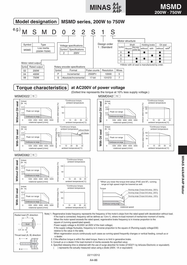
Motor structure
M S M D 0 2 2 S 1 S
Model designation
Torque characteristics at AC200V of power voltage
MSMD series, 200W to 750W
e.g.)
Symbol
MSMD
Type
Low inertia(200W-750W)
Symbol
02
04
08
Rated output
200W
400W
750W
Symbol
P
S
Format
Incremental
Absolute/Incremental
Pulse counts
2500P/r
17-bit
Resolution
10000
131072
Wires
5
7
Rotary encoder specifications
Motor rated output
Symbol
2
Specifications
200V
Voltage specificationsDesign order1 : Standard
(Dotted line represents the torque at 10% less supply voltage.)
MSMD022 1 MSMD042 1
MSMD082 1
8070
0 10 20 30 40
100
1.0
0 1000 2000 3000 4000 5000
2.0
2.0
0 1000 2000 3000 4000 5000
4.090
50
0 10 20 30 40
100
2.0
0 1000 2000 3000 4000 5000
4.0
75
50
0 10 20 30 40
100
50
0 10 20 30 40
100
4.0
0 1000 2000 3000 4000 5000
8.0
4.0
0 1000 2000 3000 4000 5000
8.0
50
0 10 20 30 40
100
1.0
0 1000 2000 3000 4000 5000
2.0
50
0 10 20 30 40
100(1.91)
(0.64)
(1.91)
(0.64)
(7.1)
(2.4)
(7.1)
(2.4)
(3.8)
(1.3)
(3.8)
(1.3)
Wit
ho
ut
Oil
seal
Wit
h O
il se
al
with Brake
without Brake
torque[N . m]
torque[N . m]
rotational speed [r/min]
rotational speed [r/min]
Peak run range
Peak run range
ambient temperature[˚C]
ambient temperature[˚C]
*Continuous torque, ambient temperature
*Continuous torque, ambient temperature
vers
us r
ated
torq
ue (
%)
vers
us r
ated
torq
ue (
%)
Continuous run range
Continuous run range
Wit
ho
ut
Oil
seal
Wit
h O
il se
al
torque[N . m]
torque[N . m]
rotational speed [r/min]
rotational speed [r/min]
Peak run range
Peak run range
ambient temperature[˚C]
ambient temperature[˚C]
*Continuous torque, ambient temperature
*Continuous torque, ambient temperature
vers
us r
ated
torq
ue (
%)
vers
us r
ated
torq
ue (
%)
Continuous run range
Continuous run range
Wit
ho
ut
Oil
seal
Wit
h O
il se
altorque[N . m]
torque[N . m]
rotational speed [r/min]
rotational speed [r/min]
Peak run range
Peak run range
ambient temperature[˚C]
ambient temperature[˚C]
*Continuous torque, ambient temperature
*Continuous torque, ambient temperature
vers
us r
ated
torq
ue (
%)
vers
us r
ated
torq
ue (
%)
Continuous run range
Continuous run range
Note) 1. Regenerative brake frequency represents the frequency of the motor's stops from the rated speed with deceleration without load. . If the load is connected, frequency will be defines as 1/(m+1), where m=load moment of inertia/rotor moment of inertia. . When the motor speed exceeds the rated speed, regenerative brake frequency is in inverse proportion to the square of (running speed/rated speed). . Power supply voltage is AC230V (at 200V of the main voltage). If the supply voltage fluctuates, frequency is in inverse proportion to the square of (Running supply voltage/230) relative to the value in the table. . When regeneration occurs continuously such cases as running speed frequently changes or vertical feeding, consult us or a dealer. 2. If the effective torque is within the rated torque, there is no limit in generative brake. 3. Consult us or a dealer if the load moment of inertia exceeds the specified value. 4. Specified releasing time is obtained with the use of surge absorber for brake (Z15D271 by Ishizuka Electronic or equivalent). ( ) represents the actually measured value using a diode (200V, 1A or equivalent)
A
B
Thrust load (A, B) direction
Radial load (P) directionL
L/2P
Shaft
Motor
*When you lower the torque limit setup (Pr5E and 5F), running range at high speed might be lowered as well.
Torque
rotational speed
Continuous running range
Running range (Torque limit setup : 300%)
Running range (Torque limit setup : 200%)
Running range (Torque limit setup : 100%)
A
B
Symbol
ST
without with withwithout
Shaft Holding brake Oil sealKey-way, center tap Round
Motor with oil seal is manufactured by order.
A4-86
MSMD200W - 750W
A4MINAS A4FA4P
MIN
AS
A4/A
4F/A
4PM
oto
r
22/11/2012
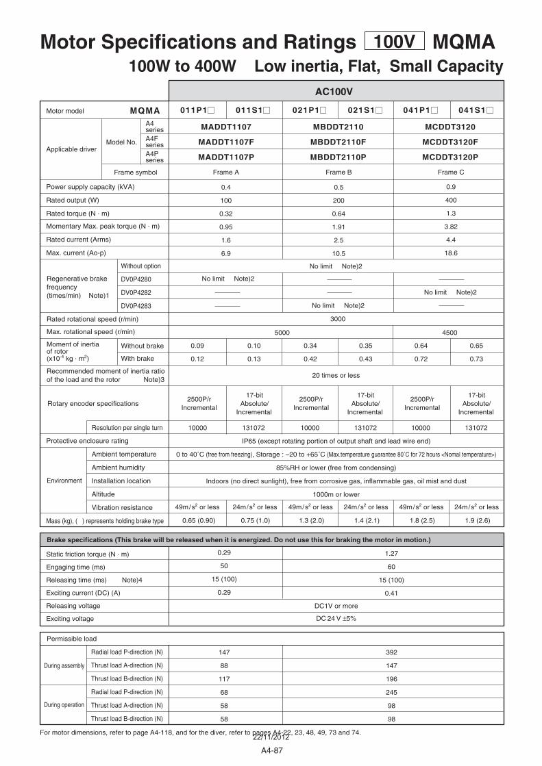
011P1 011S1 021P1 021S1 041P1 041S1
0.09
0.12
0.10
0.13
0.34
0.42
0.35
0.43
0.64
0.72
0.65
0.73
0.4
100
0.32
0.95
1.6
6.9
0.9
400
1.3
3.82
4.4
18.6
0.5
200
0.64
1.91
2.5
10.5
MQMA
3000
10000 131072 10000 131072 10000 131072
0.65 (0.90)
392
147
196
245
98
98
147
88
117
68
58
58
0.29
50
15 (100)
0.29
0.75 (1.0) 1.3 (2.0) 1.4 (2.1) 1.8 (2.5) 1.9 (2.6)
Without option
DV0P4280
DV0P4282
DV0P4283
Frame A Frame B Frame C
1.27
60
15 (100)
0.41
5000 4500
MADDT1107 MBDDT2110 MCDDT3120
MADDT1107P MBDDT2110P MCDDT3120P
20 times or less
IP65 (except rotating portion of output shaft and lead wire end)
0 to 40˚C (free from freezing), Storage : –20 to +65˚C (Max.temperature guarantee 80˚C for 72 hours <Nomal temperature>)
85%RH or lower (free from condensing)
Indoors (no direct sunlight), free from corrosive gas, inflammable gas, oil mist and dust
1000m or lower
DC1V or more
DC 24 V ±5%
Motor Specifications and Ratings 100V MQMA100W to 400W Low inertia, Flat, Small Capacity
AC100V
For motor dimensions, refer to page A4-118, and for the diver, refer to pages A4-22, 23, 48, 49, 73 and 74.
During assembly
During operation
Environment
Radial load P-direction (N)
Thrust load A-direction (N)
Thrust load B-direction (N)
Radial load P-direction (N)
Thrust load A-direction (N)
Thrust load B-direction (N)
Permissible load
Brake specifications (This brake will be released when it is energized. Do not use this for braking the motor in motion.)
Static friction torque (N . m)
Engaging time (ms)
Releasing time (ms) Note)4
Exciting current (DC) (A)
Releasing voltage
Exciting voltage
2500P/r Incremental
2500P/r Incremental
2500P/r Incremental
17-bit Absolute/
Incremental
17-bit Absolute/
Incremental
17-bit Absolute/
Incremental
Protective enclosure rating
Ambient temperature
Ambient humidity
Installation location
Altitude
Vibration resistance
Mass (kg), ( ) represents holding brake type
Rated rotational speed (r/min)
Max. rotational speed (r/min)
Power supply capacity (kVA)
Rated output (W)
Rated torque (N . m)
Momentary Max. peak torque (N . m)
Rated current (Arms)
Max. current (Ao-p)
Motor model
Applicable driver
Resolution per single turn
Rotary encoder specifications
Moment of inertiaof rotor(x10-4 kg . m2)
Recommended moment of inertia ratioof the load and the rotor Note)3
Without brake
With brake
Regenerative brakefrequency (times/min) Note)1
No limit Note)2
No limit Note)2
No limit Note)2
No limit Note)2
49m/s2 or less49m/s2 or less 24m/s2 or less 24m/s2 or less 24m/s2 or less49m/s2 or less
Model No.
Frame symbol
A4series
MADDT1107F MBDDT2110F MCDDT3120FA4FseriesA4Pseries
A4-87
22/11/2012
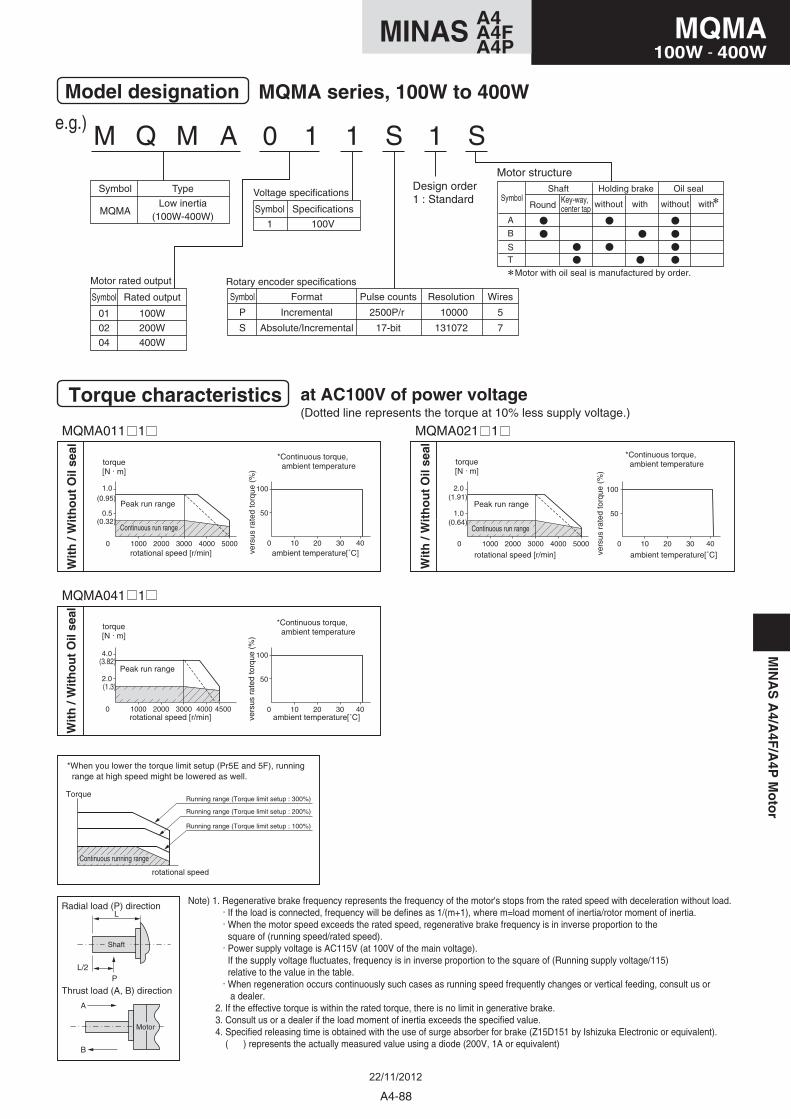
M Q M A 0 1 1 S 1 S
Wit
h /
Wit
ho
ut
Oil
seal
Model designation
Torque characteristics at AC100V of power voltage
MQMA series, 100W to 400W
e.g.)
torque[N . m]
rotational speed [r/min]
Peak run range
ambient temperature[˚C]
*Continuous torque, ambient temperature
vers
us r
ated
torq
ue (
%)
Symbol
MQMA
Type
Low inertia(100W-400W)
Symbol
01
02
04
Rated output
100W
200W
400W
Symbol
P
S
Format
Incremental
Absolute/Incremental
Pulse counts
2500P/r
17-bit
Resolution
10000
131072
Wires
5
7
Rotary encoder specificationsMotor rated output
Symbol
1
Specifications
100V
Voltage specificationsDesign order1 : Standard
Continuous run range
(Dotted line represents the torque at 10% less supply voltage.)
MQMA011 1 MQMA021 1
MQMA041 1
0.5
0 1000 2000 3000 4000 5000
1.0
50
0 10 20 30 40
100
1.0
0 1000 2000 3000 4000 5000
2.0
50
0 10 20 30 40
100
2.0
0 1000 2000 3000 4000 4500
4.0
50
0 10 20 30 40
100
(0.95)
(0.32)
(3.82)
(1.3)
(1.91)
(0.64)
Wit
h /
Wit
ho
ut
Oil
seal
torque[N . m]
rotational speed [r/min]
Peak run range
ambient temperature[˚C]
*Continuous torque, ambient temperature
vers
us r
ated
torq
ue (
%)
Continuous run range
Wit
h /
Wit
ho
ut
Oil
seal
torque[N . m]
rotational speed [r/min]
Peak run range
ambient temperature[˚C]
*Continuous torque, ambient temperature
vers
us r
ated
torq
ue (
%)
Continuous run range
Note) 1. Regenerative brake frequency represents the frequency of the motor's stops from the rated speed with deceleration without load. . If the load is connected, frequency will be defines as 1/(m+1), where m=load moment of inertia/rotor moment of inertia. . When the motor speed exceeds the rated speed, regenerative brake frequency is in inverse proportion to the square of (running speed/rated speed). . Power supply voltage is AC115V (at 100V of the main voltage). If the supply voltage fluctuates, frequency is in inverse proportion to the square of (Running supply voltage/115) relative to the value in the table. . When regeneration occurs continuously such cases as running speed frequently changes or vertical feeding, consult us or a dealer. 2. If the effective torque is within the rated torque, there is no limit in generative brake. 3. Consult us or a dealer if the load moment of inertia exceeds the specified value. 4. Specified releasing time is obtained with the use of surge absorber for brake (Z15D151 by Ishizuka Electronic or equivalent). ( ) represents the actually measured value using a diode (200V, 1A or equivalent)
A
B
Thrust load (A, B) direction
Radial load (P) directionL
L/2P
Shaft
Motor
*When you lower the torque limit setup (Pr5E and 5F), running range at high speed might be lowered as well.
Torque
rotational speed
Continuous running range
Running range (Torque limit setup : 300%)
Running range (Torque limit setup : 200%)
Running range (Torque limit setup : 100%)
Motor structure
A
B
Symbol
ST
without with withwithout
Shaft Holding brake Oil sealKey-way, center tap Round
Motor with oil seal is manufactured by order.
A4-88
MQMA100W - 400W
A4MINAS A4FA4P
MIN
AS
A4/A
4F/A
4PM
oto
r
22/11/2012
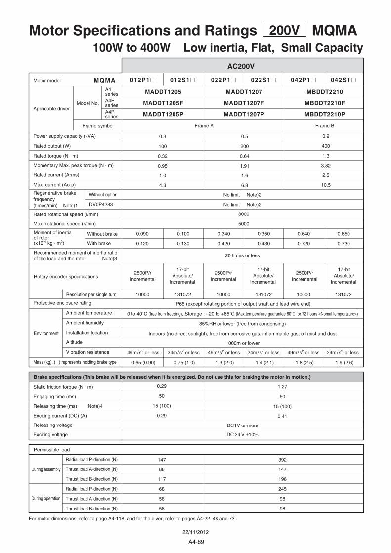
012P1 012S1 022P1 022S1 042P1 042S1
0.090
0.120
0.100
0.130
0.340
0.420
0.350
0.430
0.640
0.720
0.650
0.730
0.3
100
0.32
0.95
1.0
4.3
0.9
400
1.3
3.82
2.5
10.5
0.5
200
0.64
1.91
1.6
6.8
MQMA
3000
5000
10000 131072 10000 131072 10000 131072
0.65 (0.90)
392
147
196
245
98
98
147
88
117
68
58
58
0.29
50
15 (100)
0.29
0.75 (1.0) 1.3 (2.0) 1.4 (2.1) 1.8 (2.5) 1.9 (2.6)
Without option
DV0P4283
Frame A Frame B
1.27
60
15 (100)
0.41
MADDT1205 MADDT1207 MBDDT2210
MADDT1205P MADDT1207P MBDDT2210P
20 times or less
IP65 (except rotating portion of output shaft and lead wire end)
0 to 40˚C (free from freezing), Storage : –20 to +65˚C (Max.temperature guarantee 80˚C for 72 hours <Nomal temperature>)
85%RH or lower (free from condensing)
Indoors (no direct sunlight), free from corrosive gas, inflammable gas, oil mist and dust
1000m or lower
DC1V or more
DC 24 V ±10%
Motor Specifications and Ratings 200V MQMA100W to 400W Low inertia, Flat, Small Capacity
AC200V
For motor dimensions, refer to page A4-118, and for the diver, refer to pages A4-22, 48 and 73.
During assembly
During operation
Environment
Radial load P-direction (N)
Thrust load A-direction (N)
Thrust load B-direction (N)
Radial load P-direction (N)
Thrust load A-direction (N)
Thrust load B-direction (N)
Permissible load
Brake specifications (This brake will be released when it is energized. Do not use this for braking the motor in motion.)
Static friction torque (N . m)
Engaging time (ms)
Releasing time (ms) Note)4
Exciting current (DC) (A)
Releasing voltage
Exciting voltage
2500P/r Incremental
2500P/r Incremental
2500P/r Incremental
17-bit Absolute/
Incremental
17-bit Absolute/
Incremental
17-bit Absolute/
Incremental
Protective enclosure rating
Ambient temperature
Ambient humidity
Installation location
Altitude
Vibration resistance
Mass (kg), ( ) represents holding brake type
Rated rotational speed (r/min)
Max. rotational speed (r/min)
Power supply capacity (kVA)
Rated output (W)
Rated torque (N . m)
Momentary Max. peak torque (N . m)
Rated current (Arms)
Max. current (Ao-p)
Motor model
Applicable driver
Resolution per single turn
Rotary encoder specifications
Moment of inertiaof rotor(x10-4 kg . m2)
Recommended moment of inertia ratioof the load and the rotor Note)3
Without brake
With brake
Regenerative brakefrequency (times/min) Note)1
No limit Note)2
No limit Note)2
49m/s2 or less 49m/s2 or less24m/s2 or less 24m/s2 or less 24m/s2 or less49m/s2 or less
Model No.
Frame symbol
A4series
MADDT1205F MADDT1207F MBDDT2210FA4FseriesA4Pseries
A4-89
22/11/2012
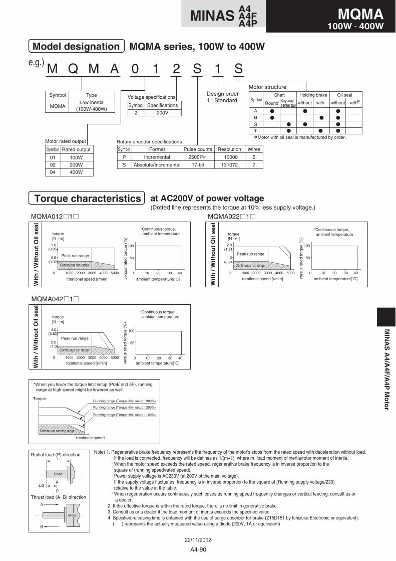
M Q M A 0 1 2 S 1 S
Model designation
Torque characteristics at AC200V of power voltage
MQMA series, 100W to 400W
e.g.)
Symbol
MQMA
Type
Low inertia(100W-400W)
Symbol
01
02
04
Rated output
100W
200W
400W
Symbol
P
S
Format
Incremental
Absolute/Incremental
Pulse counts
2500P/r
17-bit
Resolution
10000
131072
Wires
5
7
Rotary encoder specificationsMotor rated output
Symbol
2
Specifications
200V
Voltage specificationsDesign order1 : Standard
(Dotted line represents the torque at 10% less supply voltage.)
MQMA012 1 MQMA022 1
MQMA042 1
0.5
0 1000 2000 3000 4000 5000
1.0
50
0 10 20 30 40
100
1.0
0 1000 2000 3000 4000 5000
2.0
50
0 10 20 30 40
100
2.0
0 1000 2000 3000 4000 5000
4.0
50
0 10 20 30 40
100
(0.95)
(0.32)
(1.91)
(0.64)
(3.82)
(1.3)
Wit
h /
Wit
ho
ut
Oil
seal
torque[N . m]
rotational speed [r/min]
Peak run range
ambient temperature[˚C]
*Continuous torque, ambient temperature
vers
us r
ated
torq
ue (
%)
Continuous run range
Wit
h /
Wit
ho
ut
Oil
seal
torque[N . m]
rotational speed [r/min]
Peak run range
ambient temperature[˚C]
*Continuous torque, ambient temperature
vers
us r
ated
torq
ue (
%)
Continuous run range
Wit
h /
Wit
ho
ut
Oil
seal
torque[N . m]
rotational speed [r/min]
Peak run range
ambient temperature[˚C]
*Continuous torque, ambient temperature
vers
us r
ated
torq
ue (
%)
Continuous run range
Note) 1. Regenerative brake frequency represents the frequency of the motor's stops from the rated speed with deceleration without load. . If the load is connected, frequency will be defines as 1/(m+1), where m=load moment of inertia/rotor moment of inertia. . When the motor speed exceeds the rated speed, regenerative brake frequency is in inverse proportion to the square of (running speed/rated speed). . Power supply voltage is AC230V (at 200V of the main voltage). If the supply voltage fluctuates, frequency is in inverse proportion to the square of (Running supply voltage/230) relative to the value in the table. . When regeneration occurs continuously such cases as running speed frequently changes or vertical feeding, consult us or a dealer. 2. If the effective torque is within the rated torque, there is no limit in generative brake. 3. Consult us or a dealer if the load moment of inertia exceeds the specified value. 4. Specified releasing time is obtained with the use of surge absorber for brake (Z15D151 by Ishizuka Electronic or equivalent). ( ) represents the actually measured value using a diode (200V, 1A or equivalent)
A
B
Thrust load (A, B) direction
Radial load (P) directionL
L/2P
Shaft
Motor
*When you lower the torque limit setup (Pr5E and 5F), running range at high speed might be lowered as well.
Torque
rotational speed
Continuous running range
Running range (Torque limit setup : 300%)
Running range (Torque limit setup : 200%)
Running range (Torque limit setup : 100%)
Motor structure
A
B
Symbol
ST
without with withwithout
Shaft Holding brake Oil sealKey-way, center tap Round
Motor with oil seal is manufactured by order.
A4-90
MQMA100W - 400W
A4MINAS A4FA4P
MIN
AS
A4/A
4F/A
4PM
oto
r
22/11/2012
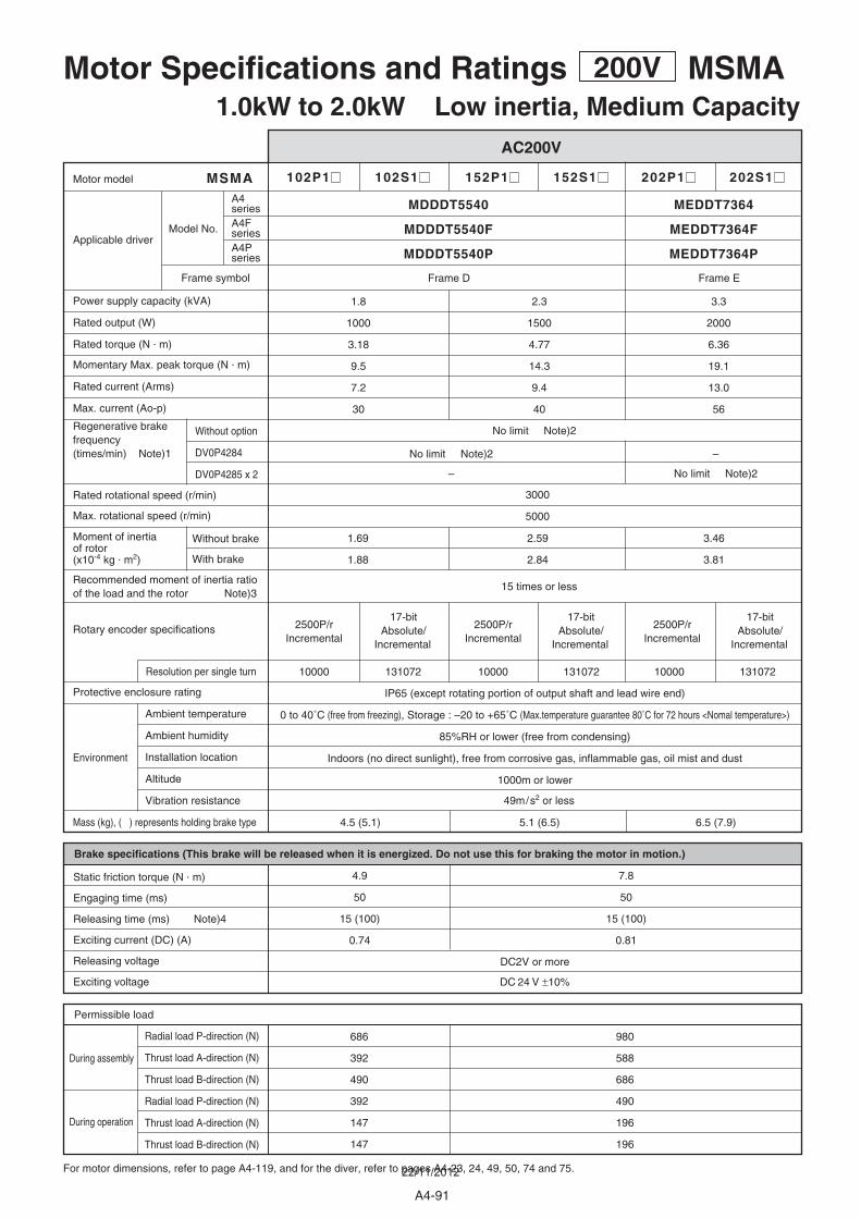
102P1 102S1 152P1 152S1 202P1 202S1
1.69
1.88
2.59
2.84
3.46
3.81
1.8
1000
3.18
9.5
7.2
30
3.3
2000
6.36
19.1
13.0
56
2.3
1500
4.77
14.3
9.4
40
Without option
DV0P4284
DV0P4285 x 2
MSMA
3000
5000
10000 131072 10000 131072 10000 131072
4.5 (5.1)
7.8
50
15 (100)
0.81
4.9
50
15 (100)
0.74
686
392
490
392
147
147
980
588
686
490
196
196
5.1 (6.5) 6.5 (7.9)
MEDDT7364MDDDT5540
MEDDT7364PMDDDT5540P
Frame EFrame D
49m/s2 or less
15 times or less
IP65 (except rotating portion of output shaft and lead wire end)
0 to 40˚C (free from freezing), Storage : –20 to +65˚C (Max.temperature guarantee 80˚C for 72 hours <Nomal temperature>)
85%RH or lower (free from condensing)
Indoors (no direct sunlight), free from corrosive gas, inflammable gas, oil mist and dust
1000m or lower
DC2V or more
DC 24 V ±10%
Motor Specifications and Ratings 200V MSMA1.0kW to 2.0kW Low inertia, Medium Capacity
AC200V
For motor dimensions, refer to page A4-119, and for the diver, refer to pages A4-23, 24, 49, 50, 74 and 75.
During assembly
During operation
Environment
Radial load P-direction (N)
Thrust load A-direction (N)
Thrust load B-direction (N)
Radial load P-direction (N)
Thrust load A-direction (N)
Thrust load B-direction (N)
Permissible load
Brake specifications (This brake will be released when it is energized. Do not use this for braking the motor in motion.)
Static friction torque (N . m)
Engaging time (ms)
Releasing time (ms) Note)4
Exciting current (DC) (A)
Releasing voltage
Exciting voltage
2500P/r Incremental
2500P/r Incremental
2500P/r Incremental
17-bit Absolute/
Incremental
17-bit Absolute/
Incremental
17-bit Absolute/
Incremental
Protective enclosure rating
Ambient temperature
Ambient humidity
Installation location
Altitude
Vibration resistance
Mass (kg), ( ) represents holding brake type
Rated rotational speed (r/min)
Max. rotational speed (r/min)
Power supply capacity (kVA)
Rated output (W)
Rated torque (N . m)
Momentary Max. peak torque (N . m)
Rated current (Arms)
Max. current (Ao-p)
Motor model
Applicable driver
Resolution per single turn
Rotary encoder specifications
Moment of inertiaof rotor(x10-4 kg . m2)
Recommended moment of inertia ratioof the load and the rotor Note)3
Without brake
With brake
Regenerative brakefrequency (times/min) Note)1
No limit Note)2
No limit Note)2 –
– No limit Note)2
Model No.
Frame symbol
A4series
MEDDT7364FMDDDT5540FA4FseriesA4Pseries
A4-91
22/11/2012
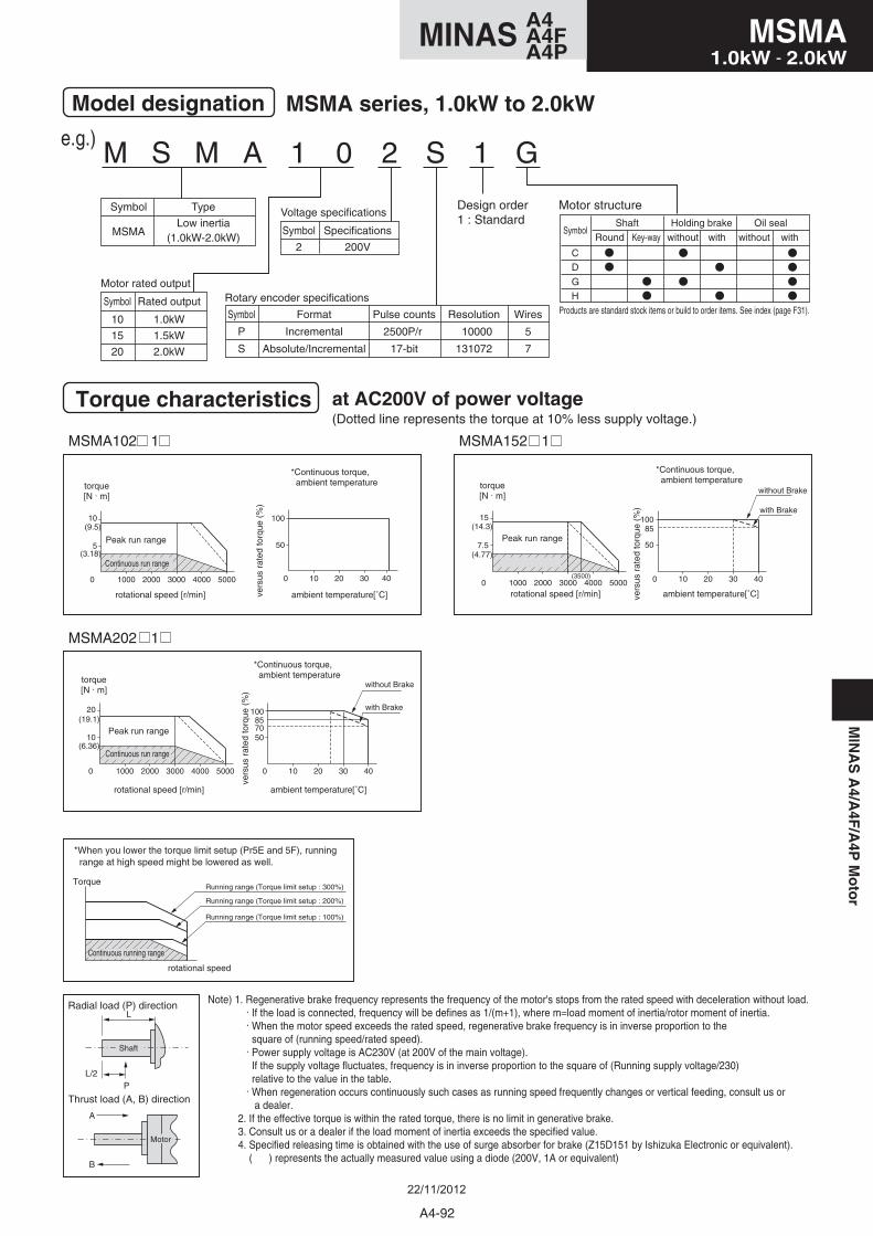
M S M A 1 0 2 S 1 G
Motor structure
Model designation
Torque characteristics at AC200V of power voltage
MSMA series, 1.0kW to 2.0kW
e.g.)
Symbol
MSMA
Type
Low inertia(1.0kW-2.0kW)
Symbol
10
15
20
Rated output
1.0kW
1.5kW
2.0kW
Symbol
P
S
Format
Incremental
Absolute/Incremental
Pulse counts
2500P/r
17-bit
Resolution
10000
131072
Wires
5
7
Rotary encoder specificationsMotor rated output
Symbol
2
Specifications
200V
Voltage specificationsDesign order1 : Standard
torque[N . m]
rotational speed [r/min]
Peak run range
ambient temperature[˚C]
*Continuous torque, ambient temperature
vers
us r
ated
torq
ue (
%)
Continuous run range
(Dotted line represents the torque at 10% less supply voltage.)
with Brake
without Brake
MSMA102 1 MSMA152 1
MSMA202 1
5
0 1000 2000 3000 4000 5000
10
50
0 10 20 30 40
100
7.5
0 1000 2000 3000(3500)
4000 5000
15
0 10 20 30 40
10085
50
10
0 1000 2000 3000 4000 5000
20
0 10 20 30 40
100857050
(9.5) (14.3)
(4.77)(3.18)
(19.1)
(6.36)
torque[N . m]
rotational speed [r/min]
Peak run range
ambient temperature[˚C]
*Continuous torque, ambient temperature
vers
us r
ated
torq
ue (
%)
Continuous run range
torque[N . m]
rotational speed [r/min]
Peak run range
ambient temperature[˚C]
*Continuous torque, ambient temperature
vers
us r
ated
torq
ue (
%)
Continuous run range
with Brake
without Brake
Note) 1. Regenerative brake frequency represents the frequency of the motor's stops from the rated speed with deceleration without load. . If the load is connected, frequency will be defines as 1/(m+1), where m=load moment of inertia/rotor moment of inertia. . When the motor speed exceeds the rated speed, regenerative brake frequency is in inverse proportion to the square of (running speed/rated speed). . Power supply voltage is AC230V (at 200V of the main voltage). If the supply voltage fluctuates, frequency is in inverse proportion to the square of (Running supply voltage/230) relative to the value in the table. . When regeneration occurs continuously such cases as running speed frequently changes or vertical feeding, consult us or a dealer. 2. If the effective torque is within the rated torque, there is no limit in generative brake. 3. Consult us or a dealer if the load moment of inertia exceeds the specified value. 4. Specified releasing time is obtained with the use of surge absorber for brake (Z15D151 by Ishizuka Electronic or equivalent). ( ) represents the actually measured value using a diode (200V, 1A or equivalent)
A
B
Thrust load (A, B) direction
Radial load (P) directionL
L/2P
Shaft
Motor
*When you lower the torque limit setup (Pr5E and 5F), running range at high speed might be lowered as well.
Torque
rotational speed
Continuous running range
Running range (Torque limit setup : 300%)
Running range (Torque limit setup : 200%)
Running range (Torque limit setup : 100%)
GH
CD
Holding brake
with
Oil sealSymbol
Shaft
without withwithoutRound Key-way
Products are standard stock items or build to order items. See index (page F31).
MIN
AS
A4/A
4F/A
4PM
oto
r
A4-92
MSMA1.0kW - 2.0kW
A4MINAS A4FA4P
22/11/2012
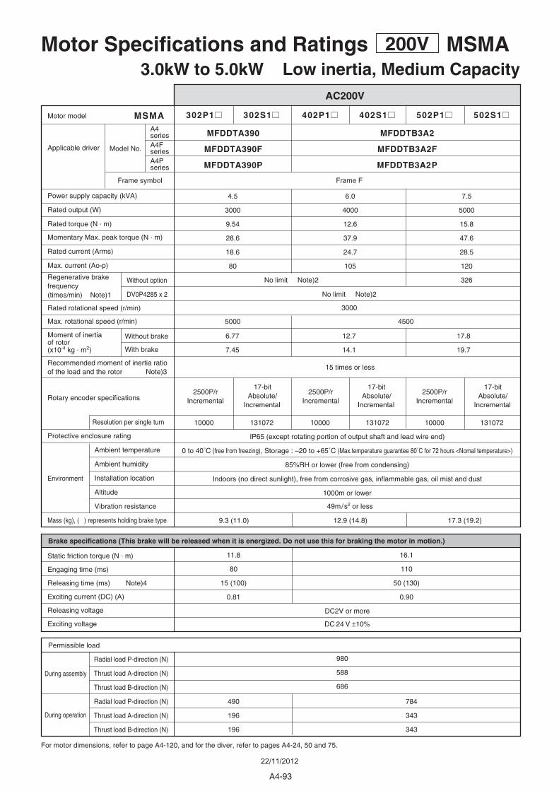
302P1 302S1 402P1 402S1 502P1 502S1
6.77
7.45
12.7
14.1
17.8
19.7
4.5
3000
9.54
28.6
18.6
80
7.5
5000
15.8
47.6
28.5
120
6.0
4000
12.6
37.9
24.7
105
Without option
DV0P4285 x 2
MSMA
45005000
3000
10000 131072 10000 131072 10000 131072
9.3 (11.0)
16.1
110
50 (130)
0.90
11.8
80
15 (100)
0.81
784
343
343
490
196
196
326
12.9 (14.8) 17.3 (19.2)
MFDDTB3A2MFDDTA390
MFDDTB3A2PMFDDTA390P
Frame F
980
588
686
49m/s2 or less
15 times or less
IP65 (except rotating portion of output shaft and lead wire end)
0 to 40˚C (free from freezing), Storage : –20 to +65˚C (Max.temperature guarantee 80˚C for 72 hours <Nomal temperature>)
85%RH or lower (free from condensing)
Indoors (no direct sunlight), free from corrosive gas, inflammable gas, oil mist and dust
1000m or lower
DC2V or more
DC 24 V ±10%
Motor Specifications and Ratings 200V MSMA3.0kW to 5.0kW Low inertia, Medium Capacity
AC200V
For motor dimensions, refer to page A4-120, and for the diver, refer to pages A4-24, 50 and 75.
During assembly
During operation
Environment
Radial load P-direction (N)
Thrust load A-direction (N)
Thrust load B-direction (N)
Radial load P-direction (N)
Thrust load A-direction (N)
Thrust load B-direction (N)
Permissible load
Brake specifications (This brake will be released when it is energized. Do not use this for braking the motor in motion.)
Static friction torque (N . m)
Engaging time (ms)
Releasing time (ms) Note)4
Exciting current (DC) (A)
Releasing voltage
Exciting voltage
2500P/r Incremental
2500P/r Incremental
2500P/r Incremental
17-bit Absolute/
Incremental
17-bit Absolute/
Incremental
17-bit Absolute/
Incremental
Protective enclosure rating
Ambient temperature
Ambient humidity
Installation location
Altitude
Vibration resistance
Mass (kg), ( ) represents holding brake type
Rated rotational speed (r/min)
Max. rotational speed (r/min)
Power supply capacity (kVA)
Rated output (W)
Rated torque (N . m)
Momentary Max. peak torque (N . m)
Rated current (Arms)
Max. current (Ao-p)
Motor model
Applicable driver
Resolution per single turn
Rotary encoder specifications
Moment of inertiaof rotor(x10-4 kg . m2)
Recommended moment of inertia ratioof the load and the rotor Note)3
Without brake
With brake
Regenerative brakefrequency (times/min) Note)1
No limit Note)2
No limit Note)2
Model No.
Frame symbol
A4series
MFDDTB3A2FMFDDTA390FA4FseriesA4Pseries
A4-93
22/11/2012
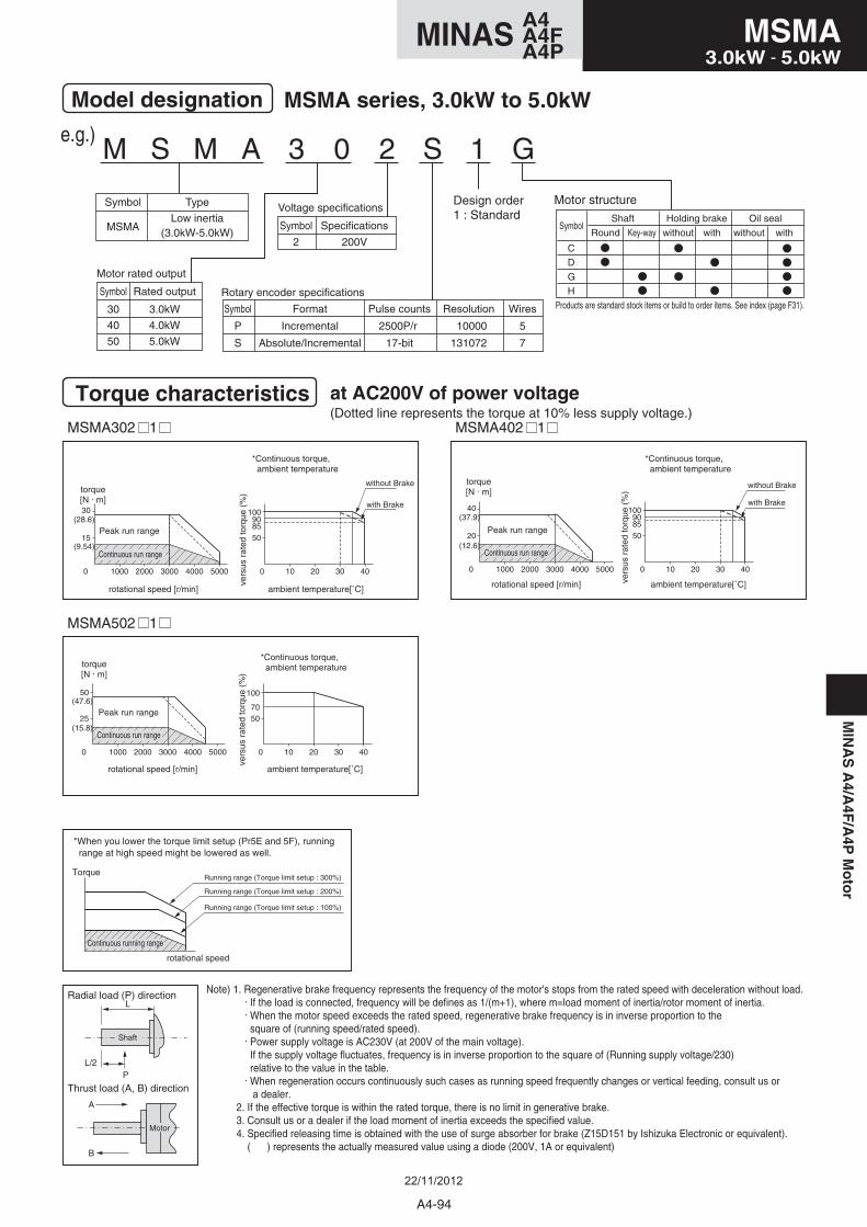
M S M A 3 0 2 S 1 G
Motor structure
Model designation MSMA series, 3.0kW to 5.0kW
e.g.)
Symbol
MSMA
Type
Low inertia(3.0kW-5.0kW)
Symbol
30
40
50
Rated output
3.0kW
4.0kW
5.0kW
Symbol
P
S
Format
Incremental
Absolute/Incremental
Pulse counts
2500P/r
17-bit
Resolution
10000
131072
Wires
5
7
Rotary encoder specifications
Motor rated output
Symbol
2
Specifications
200V
Voltage specificationsDesign order1 : Standard
Torque characteristics at AC200V of power voltage(Dotted line represents the torque at 10% less supply voltage.)
MSMA302 1
15
0 1000 2000 3000 4000 5000
30
0 10 20 30 40
1009085
50
MSMA402 1
MSMA502 1
20
0 1000 2000 3000 4000 5000
40
0 10 20 30 40
1009085
50
25
0 1000 2000 3000 4000 5000
50
0 10 20 30 40
100
7050
(28.6) (37.9)
(12.6)(9.54)
(47.6)
(15.8)
torque[N . m]
Peak run range
rotational speed [r/min] ambient temperature[˚C]
*Continuous torque, ambient temperature
vers
us r
ated
torq
ue (
%)
Continuous run range
with Brake
without Brake
torque[N . m]
Peak run range
rotational speed [r/min] ambient temperature[˚C]
*Continuous torque, ambient temperature
vers
us r
ated
torq
ue (
%)
Continuous run range
torque[N . m]
Peak run range
rotational speed [r/min] ambient temperature[˚C]
*Continuous torque, ambient temperature
vers
us r
ated
torq
ue (
%)
Continuous run range
with Brake
without Brake
Note) 1. Regenerative brake frequency represents the frequency of the motor's stops from the rated speed with deceleration without load. . If the load is connected, frequency will be defines as 1/(m+1), where m=load moment of inertia/rotor moment of inertia. . When the motor speed exceeds the rated speed, regenerative brake frequency is in inverse proportion to the square of (running speed/rated speed). . Power supply voltage is AC230V (at 200V of the main voltage). If the supply voltage fluctuates, frequency is in inverse proportion to the square of (Running supply voltage/230) relative to the value in the table. . When regeneration occurs continuously such cases as running speed frequently changes or vertical feeding, consult us or a dealer. 2. If the effective torque is within the rated torque, there is no limit in generative brake. 3. Consult us or a dealer if the load moment of inertia exceeds the specified value. 4. Specified releasing time is obtained with the use of surge absorber for brake (Z15D151 by Ishizuka Electronic or equivalent). ( ) represents the actually measured value using a diode (200V, 1A or equivalent)
A
B
Thrust load (A, B) direction
Radial load (P) directionL
L/2P
Shaft
Motor
*When you lower the torque limit setup (Pr5E and 5F), running range at high speed might be lowered as well.
Torque
rotational speed
Continuous running range
Running range (Torque limit setup : 300%)
Running range (Torque limit setup : 200%)
Running range (Torque limit setup : 100%)
GH
CD
Holding brake
with
Oil sealSymbol
Shaft
without withwithoutRound Key-way
Products are standard stock items or build to order items. See index (page F31).
A4-94
MSMA3.0kW - 5.0kW
A4MINAS A4FA4P
MIN
AS
A4/A
4F/A
4PM
oto
r
22/11/2012
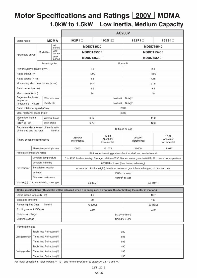
102P1 102S1 152P1 152S1
6.17
6.79
11.2
12.3
2.3
1500
7.15
21.5
9.4
40
1.8
1000
4.8
14.4
5.6
24
Without option
DV0P4284
MDMA
2000
3000
10000 131072 10000 131072
4.9
80
70 (200)
0.59
13.7
100
50 (130)
0.79
980
588
686
490
196
196
6.8 (8.7) 8.5 (10.1)
MDDDT5540MDDDT3530
MDDDT5540PMDDDT3530P
Frame D
49m/s2 or less
10 times or less
IP65 (except rotating portion of output shaft and lead wire end)
0 to 40˚C (free from freezing), Storage : –20 to +65˚C (Max.temperature guarantee 80˚C for 72 hours <Nomal temperature>)
85%RH or lower (free from condensing)
Indoors (no direct sunlight), free from corrosive gas, inflammable gas, oil mist and dust
1000m or lower
DC2V or more
DC 24 V ±10%
Motor Specifications and Ratings 200V MDMA1.0kW to 1.5kW Low inertia, Medium Capacity
AC200V
For motor dimensions, refer to page A4-121, and for the diver, refer to pages A4-23, 49 and 74.
During assembly
During operation
Environment
Radial load P-direction (N)
Thrust load A-direction (N)
Thrust load B-direction (N)
Radial load P-direction (N)
Thrust load A-direction (N)
Thrust load B-direction (N)
Permissible load
Brake specifications (This brake will be released when it is energized. Do not use this for braking the motor in motion.)
Static friction torque (N . m)
Engaging time (ms)
Releasing time (ms) Note)4
Exciting current (DC) (A)
Releasing voltage
Exciting voltage
2500P/r Incremental
2500P/r Incremental
17-bit Absolute/
Incremental
17-bit Absolute/
Incremental
Protective enclosure rating
Ambient temperature
Ambient humidity
Installation location
Altitude
Vibration resistance
Mass (kg), ( ) represents holding brake type
Rated rotational speed (r/min)
Max. rotational speed (r/min)
Power supply capacity (kVA)
Rated output (W)
Rated torque (N . m)
Momentary Max. peak torque (N . m)
Rated current (Arms)
Max. current (Ao-p)
Motor model
Applicable driver
Resolution per single turn
Rotary encoder specifications
Moment of inertiaof rotor(x10-4 kg . m2)
Recommended moment of inertia ratioof the load and the rotor Note)3
Without brake
With brake
Regenerative brakefrequency (times/min) Note)1
No limit Note)2
No limit Note)2
Model No.
Frame symbol
A4series
MDDDT5540FMDDDT3530FA4FseriesA4Pseries
A4-95
22/11/2012
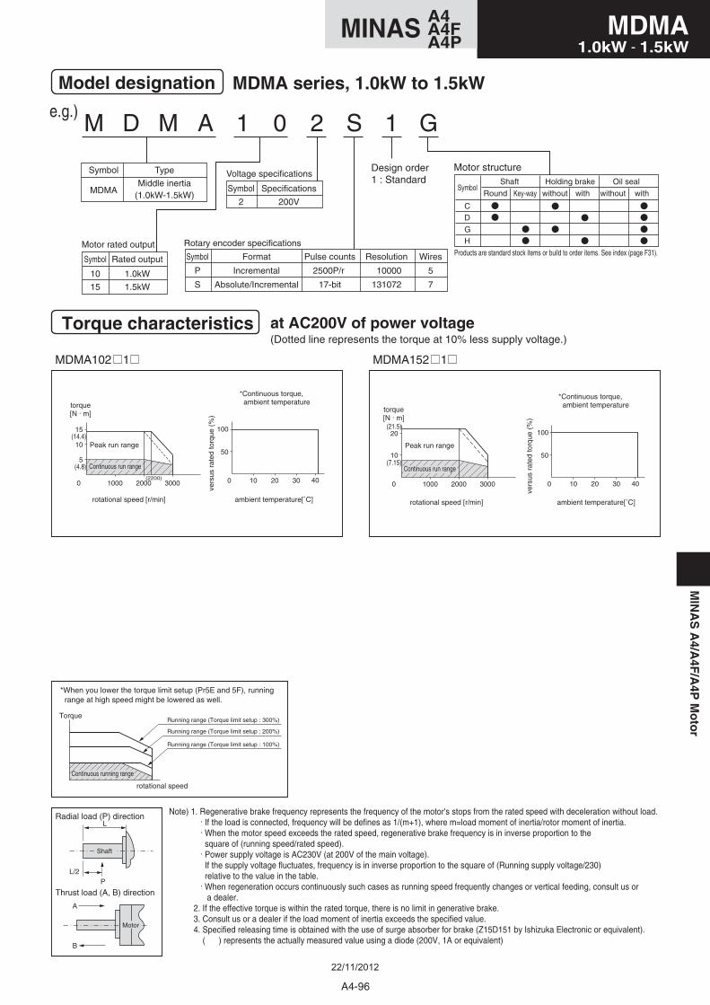
M D M A 1 0 2 S 1 G
Motor structure
Model designation MDMA series, 1.0kW to 1.5kW
Symbol
MDMA
Type
Middle inertia(1.0kW-1.5kW)
Symbol
10
15
Rated output
1.0kW
1.5kW
Symbol
P
S
Format
Incremental
Absolute/Incremental
Pulse counts
2500P/r
17-bit
Resolution
10000
131072
Wires
5
7
Rotary encoder specificationsMotor rated output
Symbol
2
Specifications
200V
Voltage specificationsDesign order1 : Standard
Torque characteristics at AC200V of power voltage(Dotted line represents the torque at 10% less supply voltage.)
e.g.)
MDMA102 1 MDMA152 1
0 1000 2000(2200)
3000
5
10
15
50
0 10 20 30 40
100
10
0
20
1000 2000 3000
50
0 10 20 30 40
100(14.4)
(4.8)
(21.5)
(7.15)
torque[N . m]
Peak run range
rotational speed [r/min] ambient temperature[˚C]
*Continuous torque, ambient temperature
vers
us r
ated
torq
ue (
%)
Continuous run range
torque[N . m]
Peak run range
rotational speed [r/min] ambient temperature[˚C]
*Continuous torque, ambient temperature
vers
us r
ated
torq
ue (
%)
Continuous run range
Note) 1. Regenerative brake frequency represents the frequency of the motor's stops from the rated speed with deceleration without load. . If the load is connected, frequency will be defines as 1/(m+1), where m=load moment of inertia/rotor moment of inertia. . When the motor speed exceeds the rated speed, regenerative brake frequency is in inverse proportion to the square of (running speed/rated speed). . Power supply voltage is AC230V (at 200V of the main voltage). If the supply voltage fluctuates, frequency is in inverse proportion to the square of (Running supply voltage/230) relative to the value in the table. . When regeneration occurs continuously such cases as running speed frequently changes or vertical feeding, consult us or a dealer. 2. If the effective torque is within the rated torque, there is no limit in generative brake. 3. Consult us or a dealer if the load moment of inertia exceeds the specified value. 4. Specified releasing time is obtained with the use of surge absorber for brake (Z15D151 by Ishizuka Electronic or equivalent). ( ) represents the actually measured value using a diode (200V, 1A or equivalent)
A
B
Thrust load (A, B) direction
Radial load (P) directionL
L/2P
Shaft
Motor
*When you lower the torque limit setup (Pr5E and 5F), running range at high speed might be lowered as well.
Torque
rotational speed
Continuous running range
Running range (Torque limit setup : 300%)
Running range (Torque limit setup : 200%)
Running range (Torque limit setup : 100%)
GH
CD
Holding brake
with
Oil sealSymbol
Shaft
without withwithoutRound Key-way
Products are standard stock items or build to order items. See index (page F31).
A4-96
MDMA1.0kW - 1.5kW
A4MINAS A4FA4P
MIN
AS
A4/A
4F/A
4PM
oto
r
22/11/2012
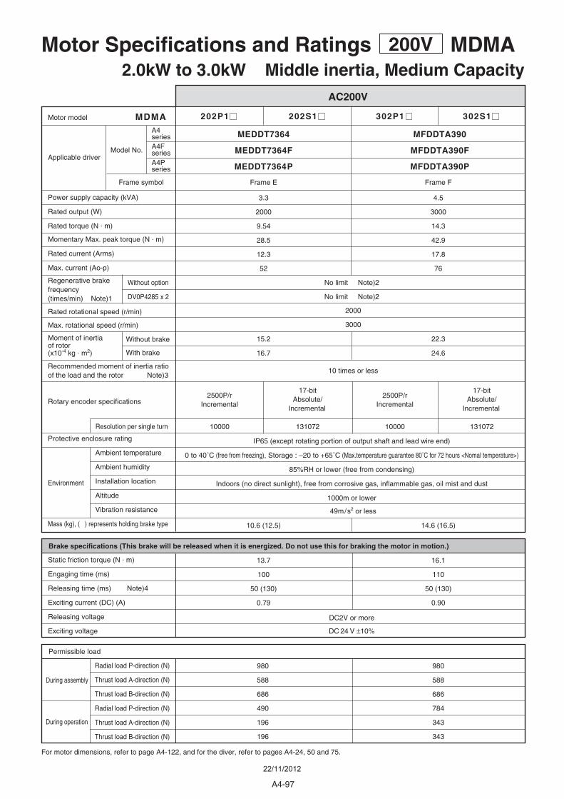
202P1 202S1 302P1 302S1
15.2
16.7
22.3
24.6
3.3
2000
9.54
28.5
12.3
52
4.5
3000
14.3
42.9
17.8
76
Without option
DV0P4285 x 2
MDMA
2000
3000
10000 131072 10000 131072
10.6 (12.5)
16.1
110
50 (130)
0.90
13.7
100
50 (130)
0.79
980
588
686
784
343
343
980
588
686
490
196
196
14.6 (16.5)
MFDDTA390MEDDT7364
MFDDTA390PMEDDT7364P
Frame FFrame E
49m/s2 or less
10 times or less
IP65 (except rotating portion of output shaft and lead wire end)
0 to 40˚C (free from freezing), Storage : –20 to +65˚C (Max.temperature guarantee 80˚C for 72 hours <Nomal temperature>)
85%RH or lower (free from condensing)
Indoors (no direct sunlight), free from corrosive gas, inflammable gas, oil mist and dust
1000m or lower
DC2V or more
DC 24 V ±10%
Motor Specifications and Ratings 200V MDMA2.0kW to 3.0kW Middle inertia, Medium Capacity
AC200V
For motor dimensions, refer to page A4-122, and for the diver, refer to pages A4-24, 50 and 75.
During assembly
During operation
Environment
Radial load P-direction (N)
Thrust load A-direction (N)
Thrust load B-direction (N)
Radial load P-direction (N)
Thrust load A-direction (N)
Thrust load B-direction (N)
Permissible load
Brake specifications (This brake will be released when it is energized. Do not use this for braking the motor in motion.)
Static friction torque (N . m)
Engaging time (ms)
Releasing time (ms) Note)4
Exciting current (DC) (A)
Releasing voltage
Exciting voltage
2500P/r Incremental
2500P/r Incremental
17-bit Absolute/
Incremental
17-bit Absolute/
Incremental
Protective enclosure rating
Ambient temperature
Ambient humidity
Installation location
Altitude
Vibration resistance
Mass (kg), ( ) represents holding brake type
Rated rotational speed (r/min)
Max. rotational speed (r/min)
Power supply capacity (kVA)
Rated output (W)
Rated torque (N . m)
Momentary Max. peak torque (N . m)
Rated current (Arms)
Max. current (Ao-p)
Motor model
Applicable driver
Resolution per single turn
Rotary encoder specifications
Moment of inertiaof rotor(x10-4 kg . m2)
Recommended moment of inertia ratioof the load and the rotor Note)3
Without brake
With brake
Regenerative brakefrequency (times/min) Note)1
No limit Note)2
No limit Note)2
Model No.
Frame symbol
A4series
MFDDTA390FMEDDT7364FA4FseriesA4Pseries
A4-97
22/11/2012
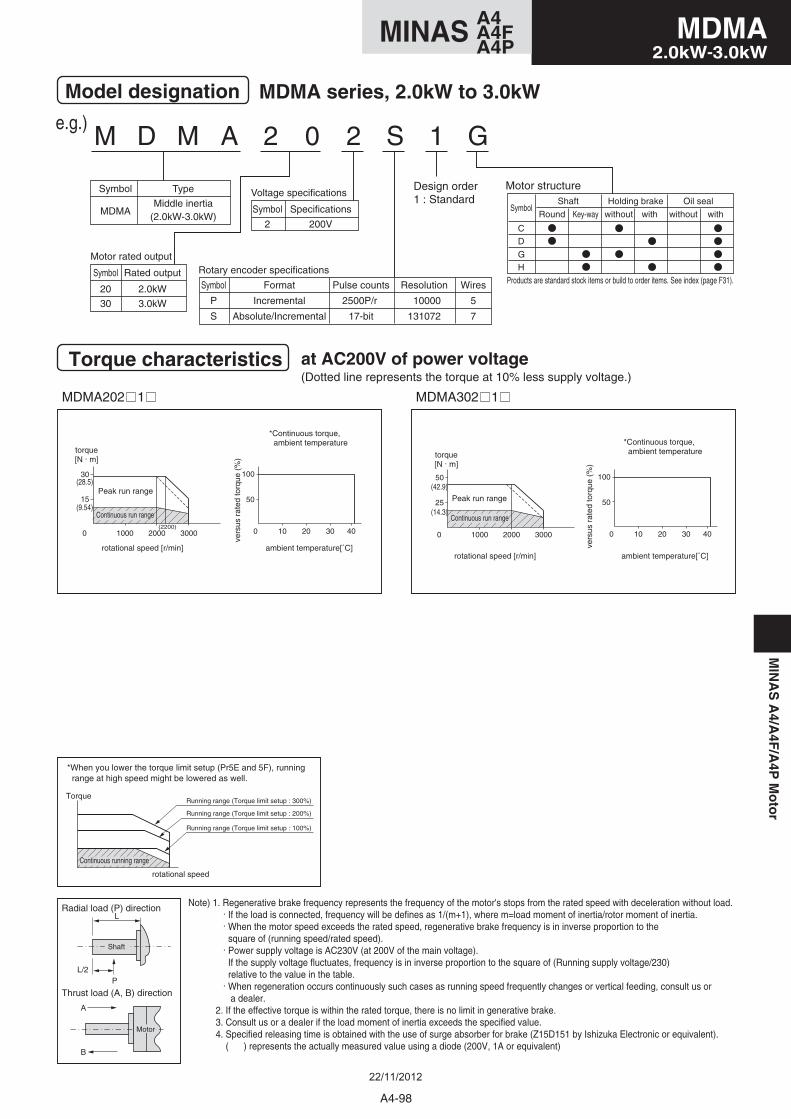
M D M A 2 0 2 S 1 G
Motor structure
Model designation MDMA series, 2.0kW to 3.0kW
Symbol
MDMA
Type
Middle inertia(2.0kW-3.0kW)
Symbol
20
30
Rated output
2.0kW
3.0kW
Symbol
P
S
Format
Incremental
Absolute/Incremental
Pulse counts
2500P/r
17-bit
Resolution
10000
131072
Wires
5
7
Rotary encoder specificationsMotor rated output
Symbol
2
Specifications
200V
Voltage specificationsDesign order1 : Standard
Torque characteristics at AC200V of power voltage(Dotted line represents the torque at 10% less supply voltage.)
e.g.)
MDMA202 1 MDMA302 1
15
0
30
1000 2000 3000(2200)
50
0 10 20 30 40
100
25
0
50
1000 2000 3000
50
0 10 20 30 40
100(28.5)
(9.54)
(42.9)
(14.3)
torque[N . m]
Peak run range
rotational speed [r/min] ambient temperature[˚C]
*Continuous torque, ambient temperature
vers
us r
ated
torq
ue (
%)
Continuous run range
torque[N . m]
Peak run range
rotational speed [r/min] ambient temperature[˚C]
*Continuous torque, ambient temperature
vers
us r
ated
torq
ue (
%)
Continuous run range
Note) 1. Regenerative brake frequency represents the frequency of the motor's stops from the rated speed with deceleration without load. . If the load is connected, frequency will be defines as 1/(m+1), where m=load moment of inertia/rotor moment of inertia. . When the motor speed exceeds the rated speed, regenerative brake frequency is in inverse proportion to the square of (running speed/rated speed). . Power supply voltage is AC230V (at 200V of the main voltage). If the supply voltage fluctuates, frequency is in inverse proportion to the square of (Running supply voltage/230) relative to the value in the table. . When regeneration occurs continuously such cases as running speed frequently changes or vertical feeding, consult us or a dealer. 2. If the effective torque is within the rated torque, there is no limit in generative brake. 3. Consult us or a dealer if the load moment of inertia exceeds the specified value. 4. Specified releasing time is obtained with the use of surge absorber for brake (Z15D151 by Ishizuka Electronic or equivalent). ( ) represents the actually measured value using a diode (200V, 1A or equivalent)
A
B
Thrust load (A, B) direction
Radial load (P) directionL
L/2P
Shaft
Motor
*When you lower the torque limit setup (Pr5E and 5F), running range at high speed might be lowered as well.
Torque
rotational speed
Continuous running range
Running range (Torque limit setup : 300%)
Running range (Torque limit setup : 200%)
Running range (Torque limit setup : 100%)
GH
CD
Holding brake
with
Oil sealSymbol
Shaft
without withwithoutRound Key-way
Products are standard stock items or build to order items. See index (page F31).
A4-98
MDMA2.0kW-3.0kW
A4MINAS A4FA4P
MIN
AS
A4/A
4F/A
4PM
oto
r
22/11/2012
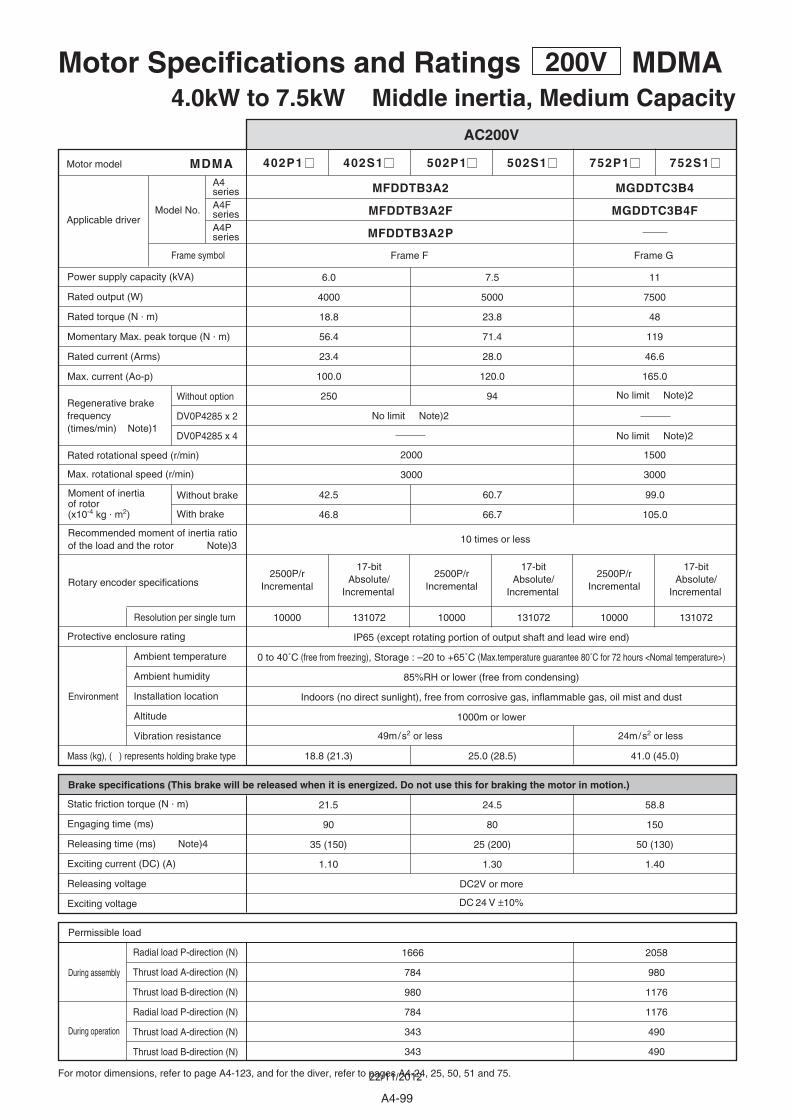
402P1 402S1 502P1 502S1
42.5
46.8
60.7
66.7
7.5
5000
23.8
71.4
28.0
120.0
94
6.0
4000
18.8
56.4
23.4
100.0
250Without option
DV0P4285 x 2
MDMA
2000
3000
1500
3000
10000 131072 10000 131072
18.8 (21.3) 25.0 (28.5)
21.5
90
35 (150)
1.10
24.5
80
25 (200)
1.30
1666
784
980
784
343
343
2058
980
1176
1176
490
490
MFDDTB3A2 MGDDTC3B4
MFDDTB3A2P
Frame F Frame G
49m/s2 or less 24m/s2 or less
10 times or less
IP65 (except rotating portion of output shaft and lead wire end)
0 to 40˚C (free from freezing), Storage : –20 to +65˚C (Max.temperature guarantee 80˚C for 72 hours <Nomal temperature>)
85%RH or lower (free from condensing)
Indoors (no direct sunlight), free from corrosive gas, inflammable gas, oil mist and dust
1000m or lower
DC2V or more
DC 24 V ±10%
Motor Specifications and Ratings 200V MDMA4.0kW to 7.5kW Middle inertia, Medium Capacity
AC200V
For motor dimensions, refer to page A4-123, and for the diver, refer to pages A4-24, 25, 50, 51 and 75.
During assembly
During operation
Environment
Radial load P-direction (N)
Thrust load A-direction (N)
Thrust load B-direction (N)
Radial load P-direction (N)
Thrust load A-direction (N)
Thrust load B-direction (N)
Permissible load
Brake specifications (This brake will be released when it is energized. Do not use this for braking the motor in motion.)
Static friction torque (N . m)
Engaging time (ms)
Releasing time (ms) Note)4
Exciting current (DC) (A)
Releasing voltage
Exciting voltage
2500P/r Incremental
2500P/r Incremental
17-bit Absolute/
Incremental
17-bit Absolute/
Incremental
752P1 752S1
99.0
105.0
11
7500
48
119
46.6
165.0
No limit Note)2
10000 131072
41.0 (45.0)
58.8
150
50 (130)
1.40
2500P/r Incremental
17-bit Absolute/
Incremental
Protective enclosure rating
Ambient temperature
Ambient humidity
Installation location
Altitude
Vibration resistance
Mass (kg), ( ) represents holding brake type
Rated rotational speed (r/min)
Max. rotational speed (r/min)
Power supply capacity (kVA)
Rated output (W)
Rated torque (N . m)
Momentary Max. peak torque (N . m)
Rated current (Arms)
Max. current (Ao-p)
Motor model
Applicable driver
Resolution per single turn
Rotary encoder specifications
Moment of inertiaof rotor(x10-4 kg . m2)
Recommended moment of inertia ratioof the load and the rotor Note)3
Without brake
With brake
Regenerative brakefrequency (times/min) Note)1
No limit Note)2
No limit Note)2DV0P4285 x 4
Model No.
Frame symbol
A4series
MFDDTB3A2F MGDDTC3B4FA4FseriesA4Pseries
A4-99
22/11/2012
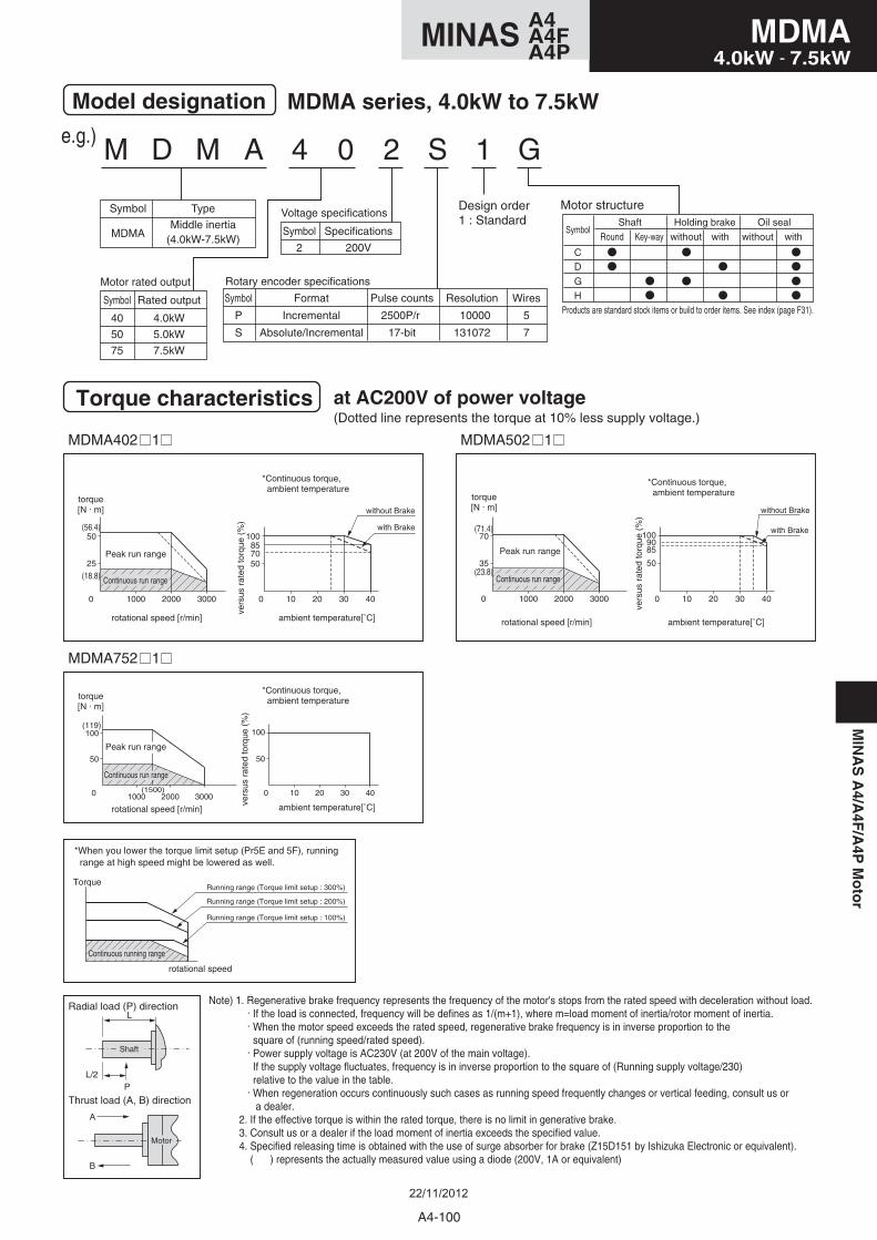
M D M A 4 0 2 S 1 G
Motor structure
Model designation MDMA series, 4.0kW to 7.5kW
Symbol
MDMA
Type
Middle inertia(4.0kW-7.5kW)
Symbol
40
50
75
Rated output
4.0kW
5.0kW
7.5kW
Symbol
P
S
Format
Incremental
Absolute/Incremental
Pulse counts
2500P/r
17-bit
Resolution
10000
131072
Wires
5
7
Rotary encoder specificationsMotor rated output
Symbol
2
Specifications
200V
Voltage specificationsDesign order1 : Standard
Torque characteristics at AC200V of power voltage(Dotted line represents the torque at 10% less supply voltage.)
e.g.)
MDMA402 1
MDMA752 1
MDMA502 1
0 10 20 30 40
10085705025
0
50
1000 2000 3000
35
0
70
1000 2000 3000 0 10 20 30 40
1009085
50
(18.8)
(56.4) (71.4)
(23.8)
torque[N . m]
torque[N . m]
rotational speed [r/min]
rotational speed [r/min]
ambient temperature[˚C]
ambient temperature[˚C]
*Continuous torque, ambient temperature
*Continuous torque, ambient temperature
vers
us r
ated
torq
ue (
%)
vers
us r
ated
torq
ue (
%)
with Brake
without Brake
torque[N . m]
Peak run range
rotational speed [r/min] ambient temperature[˚C]
*Continuous torque, ambient temperature
vers
us r
ated
torq
ue (
%)
Continuous run range
with Brake
without Brake
Note) 1. Regenerative brake frequency represents the frequency of the motor's stops from the rated speed with deceleration without load. . If the load is connected, frequency will be defines as 1/(m+1), where m=load moment of inertia/rotor moment of inertia. . When the motor speed exceeds the rated speed, regenerative brake frequency is in inverse proportion to the square of (running speed/rated speed). . Power supply voltage is AC230V (at 200V of the main voltage). If the supply voltage fluctuates, frequency is in inverse proportion to the square of (Running supply voltage/230) relative to the value in the table. . When regeneration occurs continuously such cases as running speed frequently changes or vertical feeding, consult us or a dealer. 2. If the effective torque is within the rated torque, there is no limit in generative brake. 3. Consult us or a dealer if the load moment of inertia exceeds the specified value. 4. Specified releasing time is obtained with the use of surge absorber for brake (Z15D151 by Ishizuka Electronic or equivalent). ( ) represents the actually measured value using a diode (200V, 1A or equivalent)
A
B
Thrust load (A, B) direction
Radial load (P) directionL
L/2P
Shaft
Motor
*When you lower the torque limit setup (Pr5E and 5F), running range at high speed might be lowered as well.
Torque
rotational speed
Continuous running range
Running range (Torque limit setup : 300%)
Running range (Torque limit setup : 200%)
Running range (Torque limit setup : 100%)
GH
CD
Holding brake
with
Oil sealSymbol
Shaft
without withwithoutRound Key-way
Products are standard stock items or build to order items. See index (page F31).
50
0
100(119)
1000(1500)
2000 3000 0 10 20 30 40
100
50
Peak run range
Peak run range
Continuous run range
Continuous run range
A4-100
MDMA4.0kW - 7.5kW
A4MINAS A4FA4P
MIN
AS
A4/A
4F/A
4PM
oto
r
22/11/2012
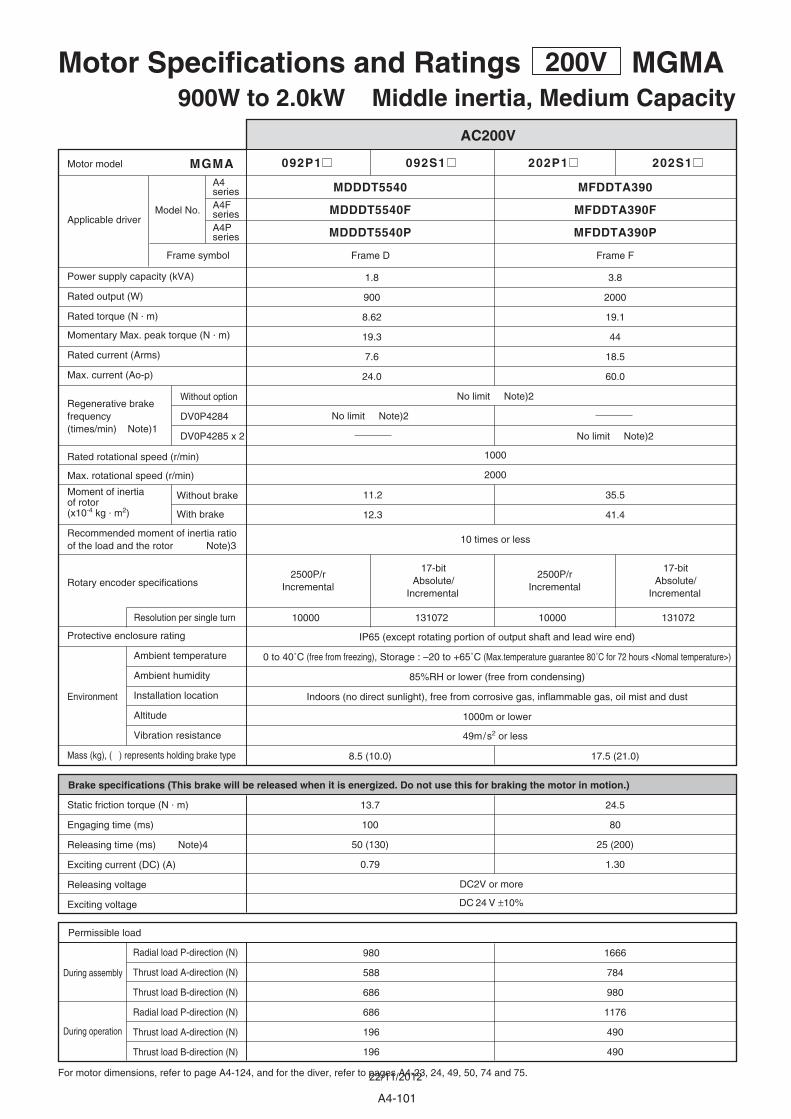
092P1 092S1 202P1 202S1
11.2
12.3
35.5
41.4
1.8
900
8.62
19.3
7.6
24.0
3.8
2000
19.1
44
18.5
60.0
Without option
DV0P4284
DV0P4285 x 2
MGMA
1000
2000
10000 131072 10000 131072
13.7
100
50 (130)
0.79
24.5
80
25 (200)
1.30
980
588
686
686
196
196
1666
784
980
1176
490
490
8.5 (10.0) 17.5 (21.0)
MDDDT5540 MFDDTA390
MDDDT5540P MFDDTA390P
Frame D Frame F
49m/s2 or less
10 times or less
IP65 (except rotating portion of output shaft and lead wire end)
0 to 40˚C (free from freezing), Storage : –20 to +65˚C (Max.temperature guarantee 80˚C for 72 hours <Nomal temperature>)
85%RH or lower (free from condensing)
Indoors (no direct sunlight), free from corrosive gas, inflammable gas, oil mist and dust
1000m or lower
DC2V or more
DC 24 V ±10%
Motor Specifications and Ratings 200V MGMA900W to 2.0kW Middle inertia, Medium Capacity
AC200V
For motor dimensions, refer to page A4-124, and for the diver, refer to pages A4-23, 24, 49, 50, 74 and 75.
During assembly
During operation
Environment
Radial load P-direction (N)
Thrust load A-direction (N)
Thrust load B-direction (N)
Radial load P-direction (N)
Thrust load A-direction (N)
Thrust load B-direction (N)
Permissible load
Brake specifications (This brake will be released when it is energized. Do not use this for braking the motor in motion.)
Static friction torque (N . m)
Engaging time (ms)
Releasing time (ms) Note)4
Exciting current (DC) (A)
Releasing voltage
Exciting voltage
2500P/r Incremental
2500P/r Incremental
17-bit Absolute/
Incremental
17-bit Absolute/
Incremental
Protective enclosure rating
Ambient temperature
Ambient humidity
Installation location
Altitude
Vibration resistance
Mass (kg), ( ) represents holding brake type
Rated rotational speed (r/min)
Max. rotational speed (r/min)
Power supply capacity (kVA)
Rated output (W)
Rated torque (N . m)
Momentary Max. peak torque (N . m)
Rated current (Arms)
Max. current (Ao-p)
Motor model
Applicable driver
Resolution per single turn
Rotary encoder specifications
Moment of inertiaof rotor(x10-4 kg . m2)
Recommended moment of inertia ratioof the load and the rotor Note)3
Without brake
With brake
Regenerative brakefrequency (times/min) Note)1
No limit Note)2
No limit Note)2
No limit Note)2
Model No.
Frame symbol
A4series
MDDDT5540F MFDDTA390FA4FseriesA4Pseries
A4-101
22/11/2012

M G M A 0 9 2 S 1 G
Motor structure
Model designation MGMA series, 900W to 2.0kW
Symbol
MGMA
Type
Middle inertia(900W-2.0kW)
Symbol
09
20
Rated output
900W
2.0kWSymbol
P
S
Format
Incremental
Absolute/Incremental
Pulse counts
2500P/r
17-bit
Resolution
10000
131072
Wires
5
7
Rotary encoder specifications
Motor rated output
Symbol
2
Specifications
200V
Voltage specificationsDesign order1 : Standard
torque[N . m]
Peak run range
rotational speed [r/min] ambient temperature[˚C]
*Continuous torque, ambient temperature
vers
us r
ated
torq
ue (
%)
Continuous run range
Torque characteristics at AC200V of power voltage(Dotted line represents the torque at 10% less supply voltage.)
e.g.)
MGMA092 1
10
0
20
1000 2000
50
0 10 20 30 40
100
MGMA202 1
25
0
50
1000 2000
50
0 10 20 30 40
100
(19.3)
(8.62)
(44)
(19.1)
torque[N . m]
Peak run range
rotational speed [r/min] ambient temperature[˚C]
*Continuous torque, ambient temperature
vers
us r
ated
torq
ue (
%)
Continuous run range
Note) 1. Regenerative brake frequency represents the frequency of the motor's stops from the rated speed with deceleration without load. . If the load is connected, frequency will be defines as 1/(m+1), where m=load moment of inertia/rotor moment of inertia. . When the motor speed exceeds the rated speed, regenerative brake frequency is in inverse proportion to the square of (running speed/rated speed). . Power supply voltage is AC230V (at 200V of the main voltage). If the supply voltage fluctuates, frequency is in inverse proportion to the square of (Running supply voltage/230) relative to the value in the table. . When regeneration occurs continuously such cases as running speed frequently changes or vertical feeding, consult us or a dealer. 2. If the effective torque is within the rated torque, there is no limit in generative brake. 3. Consult us or a dealer if the load moment of inertia exceeds the specified value. 4. Specified releasing time is obtained with the use of surge absorber for brake (Z15D151 by Ishizuka Electronic or equivalent). ( ) represents the actually measured value using a diode (200V, 1A or equivalent)
A
B
Thrust load (A, B) direction
Radial load (P) directionL
L/2P
Shaft
Motor
*When you lower the torque limit setup (Pr5E and 5F), running range at high speed might be lowered as well.
Torque
rotational speed
Continuous running range
Running range (Torque limit setup : 300%)
Running range (Torque limit setup : 200%)
Running range (Torque limit setup : 100%)
GH
CD
Holding brake
with
Oil sealSymbol
Shaft
without withwithoutRound Key-way
Products are standard stock items or build to order items. See index (page F31).
A4-102
MGMA900W - 2.0kW
A4MINAS A4FA4P
MIN
AS
A4/A
4F/A
4PM
oto
r
22/11/2012
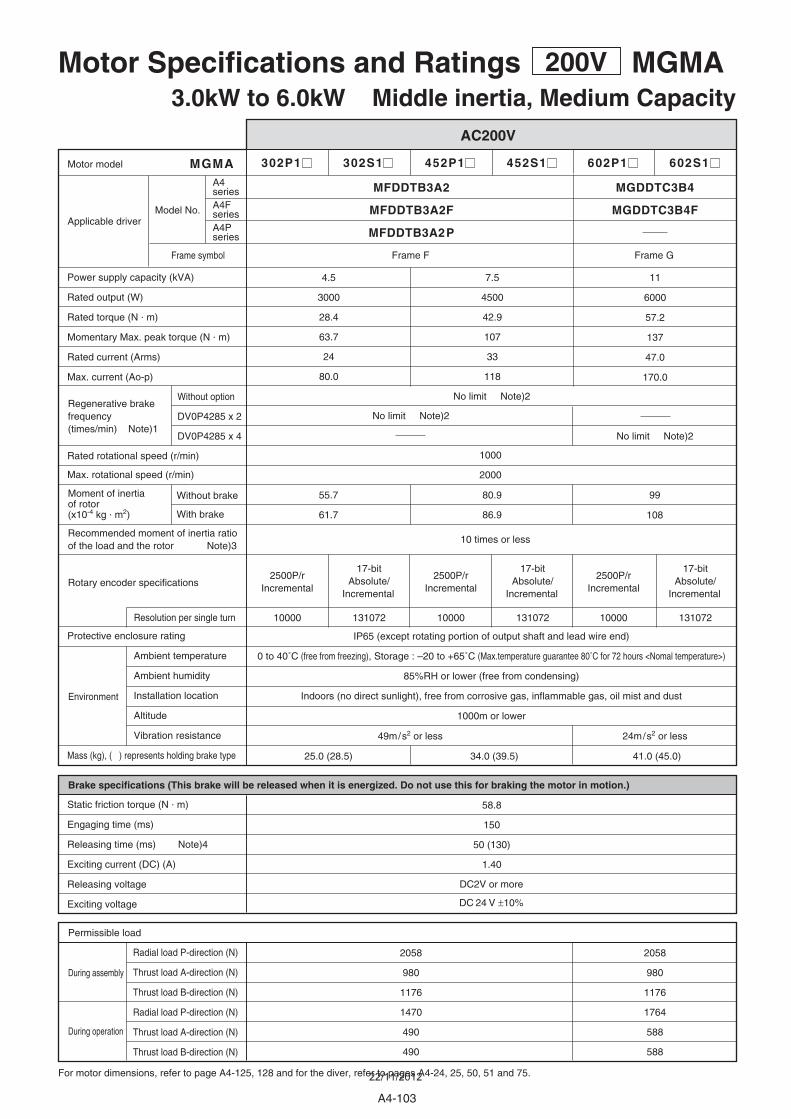
302P1 302S1 452P1 452S1
55.7
61.7
80.9
86.9
4.5
3000
28.4
63.7
24
80.0
7.5
4500
42.9
107
33
118
Without option
DV0P4285 x 2
DV0P4285 x 4
MGMA
1000
2000
10000 131072 10000 131072
25.0 (28.5) 34.0 (39.5)
58.8
150
50 (130)
1.40
2058
980
1176
1470
490
490
2058
980
1176
1764
588
588
MFDDTB3A2
MFDDTB3A2P
Frame F
MGDDTC3B4
Frame G
49m/s2 or less 24m/s2 or less
10 times or less
IP65 (except rotating portion of output shaft and lead wire end)
0 to 40˚C (free from freezing), Storage : –20 to +65˚C (Max.temperature guarantee 80˚C for 72 hours <Nomal temperature>)
85%RH or lower (free from condensing)
Indoors (no direct sunlight), free from corrosive gas, inflammable gas, oil mist and dust
1000m or lower
DC2V or more
DC 24 V ±10%
Motor Specifications and Ratings 200V MGMA3.0kW to 6.0kW Middle inertia, Medium Capacity
AC200V
For motor dimensions, refer to page A4-125, 128 and for the diver, refer to pages A4-24, 25, 50, 51 and 75.
During assembly
During operation
Environment
Radial load P-direction (N)
Thrust load A-direction (N)
Thrust load B-direction (N)
Radial load P-direction (N)
Thrust load A-direction (N)
Thrust load B-direction (N)
Permissible load
Brake specifications (This brake will be released when it is energized. Do not use this for braking the motor in motion.)
Static friction torque (N . m)
Engaging time (ms)
Releasing time (ms) Note)4
Exciting current (DC) (A)
Releasing voltage
Exciting voltage
2500P/r Incremental
2500P/r Incremental
17-bit Absolute/
Incremental
17-bit Absolute/
Incremental
602P1 602S1
99
108
11
6000
57.2
137
47.0
170.0
10000 131072
41.0 (45.0)
2500P/r Incremental
17-bit Absolute/
Incremental
Protective enclosure rating
Ambient temperature
Ambient humidity
Installation location
Altitude
Vibration resistance
Mass (kg), ( ) represents holding brake type
Rated rotational speed (r/min)
Max. rotational speed (r/min)
Power supply capacity (kVA)
Rated output (W)
Rated torque (N . m)
Momentary Max. peak torque (N . m)
Rated current (Arms)
Max. current (Ao-p)
Motor model
Applicable driver
Resolution per single turn
Rotary encoder specifications
Moment of inertiaof rotor(x10-4 kg . m2)
Recommended moment of inertia ratioof the load and the rotor Note)3
Without brake
With brake
Regenerative brakefrequency (times/min) Note)1
No limit Note)2
No limit Note)2
No limit Note)2
Model No.
Frame symbol
A4series
MFDDTB3A2F MGDDTC3B4FA4FseriesA4Pseries
A4-103
22/11/2012
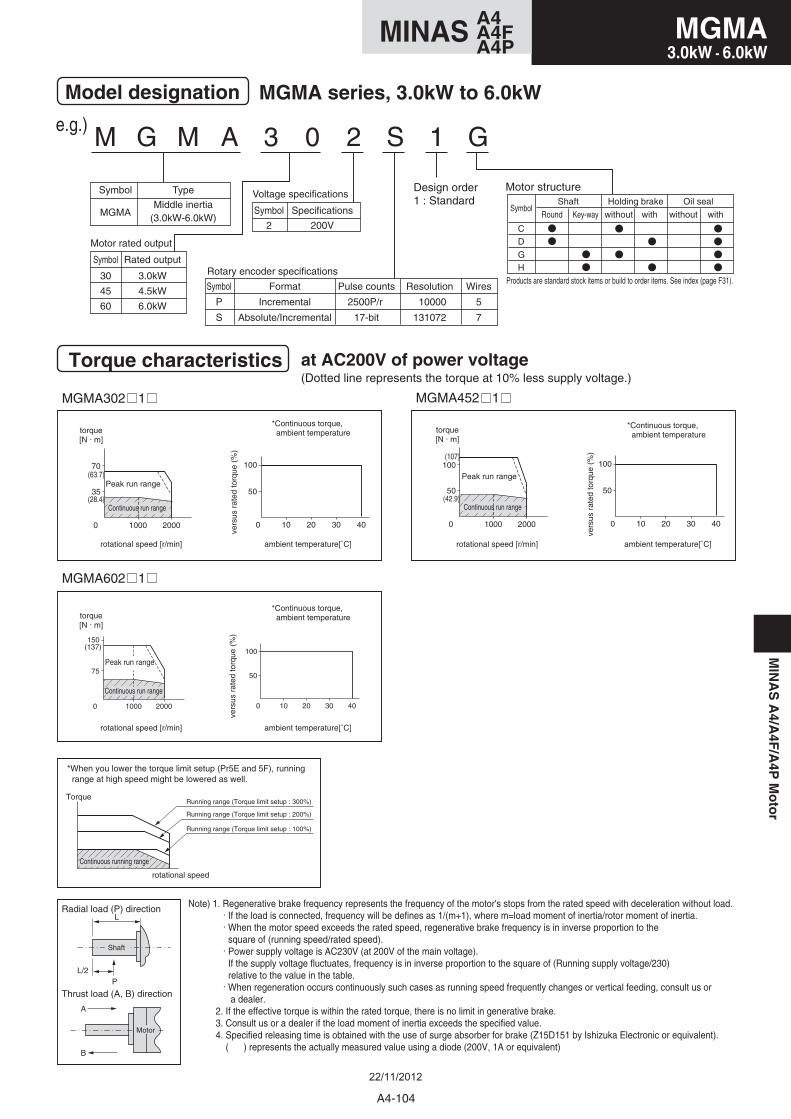
M G M A 3 0 2 S 1 G
Motor structure
Model designation MGMA series, 3.0kW to 6.0kW
Symbol
MGMA
Type
Middle inertia(3.0kW-6.0kW)
Symbol
30
45
60
Rated output
3.0kW
4.5kW
6.0kW
Symbol
P
S
Format
Incremental
Absolute/Incremental
Pulse counts
2500P/r
17-bit
Resolution
10000
131072
Wires
5
7
Rotary encoder specifications
Motor rated output
Symbol
2
Specifications
200V
Voltage specificationsDesign order1 : Standard
Torque characteristics at AC200V of power voltage(Dotted line represents the torque at 10% less supply voltage.)
e.g.)
MGMA452 1 MGMA302 1
MGMA602 1
35
0
70
1000 2000
50
0 10 20 30 40
100
50
0
100
1000 2000
50
0 10 20 30 40
100(63.7)
(107)
(42.9)(28.4)
torque[N . m]
torque[N . m]
Peak run range
rotational speed [r/min] ambient temperature[˚C]
rotational speed [r/min] ambient temperature[˚C]
*Continuous torque, ambient temperature
*Continuous torque, ambient temperature
vers
us r
ated
torq
ue (
%)
vers
us r
ated
torq
ue (
%)
Continuous run range
torque[N . m]
Peak run range
rotational speed [r/min] ambient temperature[˚C]
*Continuous torque, ambient temperature
vers
us r
ated
torq
ue (
%)
Continuous run range
Note) 1. Regenerative brake frequency represents the frequency of the motor's stops from the rated speed with deceleration without load. . If the load is connected, frequency will be defines as 1/(m+1), where m=load moment of inertia/rotor moment of inertia. . When the motor speed exceeds the rated speed, regenerative brake frequency is in inverse proportion to the square of (running speed/rated speed). . Power supply voltage is AC230V (at 200V of the main voltage). If the supply voltage fluctuates, frequency is in inverse proportion to the square of (Running supply voltage/230) relative to the value in the table. . When regeneration occurs continuously such cases as running speed frequently changes or vertical feeding, consult us or a dealer. 2. If the effective torque is within the rated torque, there is no limit in generative brake. 3. Consult us or a dealer if the load moment of inertia exceeds the specified value. 4. Specified releasing time is obtained with the use of surge absorber for brake (Z15D151 by Ishizuka Electronic or equivalent). ( ) represents the actually measured value using a diode (200V, 1A or equivalent)
A
B
Thrust load (A, B) direction
Radial load (P) directionL
L/2P
Shaft
Motor
*When you lower the torque limit setup (Pr5E and 5F), running range at high speed might be lowered as well.
Torque
rotational speed
Continuous running range
Running range (Torque limit setup : 300%)
Running range (Torque limit setup : 200%)
Running range (Torque limit setup : 100%)
GH
CD
Holding brake
with
Oil sealSymbol
Shaft
without withwithoutRound Key-way
Products are standard stock items or build to order items. See index (page F31).
75
0
150(137)
1000 2000
50
0 10 20 30 40
100
Continuous run range
Peak run range
MIN
AS
A4/A
4F/A
4PM
oto
r
A4-104
MGMA3.0kW - 6.0kW
A4MINAS A4FA4P
22/11/2012
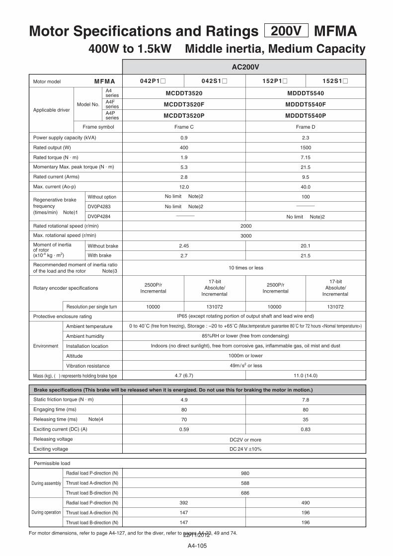
042P1 042S1 152P1 152S1
2.45
2.7
20.1
21.5
0.9
400
1.9
5.3
2.8
12.0
No limit Note)2
2.3
1500
7.15
21.5
9.5
40.0
100Without option
MFMA
2000
3000
13107210000 10000 131072
4.7 (6.7)
7.8
80
35
0.83
4.9
80
70
0.59
980
588
686
490
196
196
392
147
147
11.0 (14.0)
DV0P4283
DV0P4284
MDDDT5540
Frame D
MCDDT3520
MDDDT5540PMCDDT3520P
Frame C
49m/s2 or less
10 times or less
IP65 (except rotating portion of output shaft and lead wire end)
0 to 40˚C (free from freezing), Storage : –20 to +65˚C (Max.temperature guarantee 80˚C for 72 hours <Nomal temperature>)
85%RH or lower (free from condensing)
Indoors (no direct sunlight), free from corrosive gas, inflammable gas, oil mist and dust
1000m or lower
DC2V or more
DC 24 V ±10%
Motor Specifications and Ratings 200V MFMA400W to 1.5kW Middle inertia, Medium Capacity
AC200V
For motor dimensions, refer to page A4-127, and for the diver, refer to pages A4-23, 49 and 74.
During assembly
During operation
Environment
Radial load P-direction (N)
Thrust load A-direction (N)
Thrust load B-direction (N)
Radial load P-direction (N)
Thrust load A-direction (N)
Thrust load B-direction (N)
Permissible load
Brake specifications (This brake will be released when it is energized. Do not use this for braking the motor in motion.)
Static friction torque (N . m)
Engaging time (ms)
Releasing time (ms) Note)4
Exciting current (DC) (A)
Releasing voltage
Exciting voltage
2500P/r Incremental
2500P/r Incremental
17-bit Absolute/
Incremental
17-bit Absolute/
Incremental
Protective enclosure rating
Ambient temperature
Ambient humidity
Installation location
Altitude
Vibration resistance
Mass (kg), ( ) represents holding brake type
Rated rotational speed (r/min)
Max. rotational speed (r/min)
Power supply capacity (kVA)
Rated output (W)
Rated torque (N . m)
Momentary Max. peak torque (N . m)
Rated current (Arms)
Max. current (Ao-p)
Motor model
Applicable driver
Resolution per single turn
Rotary encoder specifications
Moment of inertiaof rotor(x10-4 kg . m2)
Recommended moment of inertia ratioof the load and the rotor Note)3
Without brake
With brake
Regenerative brakefrequency (times/min) Note)1
No limit Note)2
No limit Note)2
Model No.
Frame symbol
A4series
MDDDT5540FMCDDT3520FA4FseriesA4Pseries
A4-105
22/11/2012

M F M A 0 4 2 S 1 G
Motor structure
Model designation MFMA series, 400W to 1.5kW
Symbol
MFMA
Type
Middle inertia(400W-1.5kW)
Symbol
04
15
Rated output
400W
1.5kW Symbol
P
S
Format
Incremental
Absolute/Incremental
Pulse counts
2500P/r
17-bit
Resolution
10000
131072
Wires
5
7
Rotary encoder specifications
Motor rated output
Symbol
2
Specifications
200V
Voltage specificationsDesign order1 : Standard
Torque characteristics at AC200V of power voltage(Dotted line represents the torque at 10% less supply voltage.)
e.g.)
MFMA042 1 MFMA152 1
2.5
0
5
1000 2000 3000
50
0 10 20 30 40
100
50
0 10 20 30 40
100
10
0
20
1000 2000 3000
(5.3) (21.5)
(7.15)(1.9)
torque[N . m]
Peak run range
rotational speed [r/min] ambient temperature[˚C]
*Continuous torque, ambient temperature
vers
us r
ated
torq
ue (
%)
Continuous run range
torque[N . m]
Peak run range
rotational speed [r/min] ambient temperature[˚C]
*Continuous torque, ambient temperature
vers
us r
ated
torq
ue (
%)
Continuous run range
Note) 1. Regenerative brake frequency represents the frequency of the motor's stops from the rated speed with deceleration without load. . If the load is connected, frequency will be defines as 1/(m+1), where m=load moment of inertia/rotor moment of inertia. . When the motor speed exceeds the rated speed, regenerative brake frequency is in inverse proportion to the square of (running speed/rated speed). . Power supply voltage is AC230V (at 200V of the main voltage). If the supply voltage fluctuates, frequency is in inverse proportion to the square of (Running supply voltage/230) relative to the value in the table. . When regeneration occurs continuously such cases as running speed frequently changes or vertical feeding, consult us or a dealer. 2. If the effective torque is within the rated torque, there is no limit in generative brake. 3. Consult us or a dealer if the load moment of inertia exceeds the specified value. 4. Specified releasing time is obtained with the use of surge absorber for brake (Z15D151 by Ishizuka Electronic or equivalent). ( ) represents the actually measured value using a diode (200V, 1A or equivalent)
A
B
Thrust load (A, B) direction
Radial load (P) directionL
L/2P
Shaft
Motor
*When you lower the torque limit setup (Pr5E and 5F), running range at high speed might be lowered as well.
Torque
rotational speed
Continuous running range
Running range (Torque limit setup : 300%)
Running range (Torque limit setup : 200%)
Running range (Torque limit setup : 100%)
GH
CD
Holding brake
with
Oil sealSymbol
Shaft
without withwithoutRound Key-way
Products are standard stock items or build to order items. See index (page F31).
MIN
AS
A4/A
4F/A
4PM
oto
r
A4-106
MFMA400W - 1.5kW
A4MINAS A4FA4P
22/11/2012

252P1 252S1 452P1 452S1
41.3
45.3
72.3
78.5
3.8
2500
11.8
30.4
13.4
57.0
75
6.8
4500
21.5
54.9
23.5
100.0
67
375
Without option
MFMA
2000
3000
13107210000 10000 131072
14.8 (17.5)
31.4
150
100 (450)
0.75
21.6
150
100 (450)
0.75
1862
686
686
784
294
294
19.9 (24.3)
MEDDT7364 MFDDTB3A2
MEDDT7364P MFDDTB3A2P
DV0P4285 x 2
Frame E Frame F
49m/s2 or less
10 times or less
IP65 (except rotating portion of output shaft and lead wire end)
0 to 40˚C (free from freezing), Storage : –20 to +65˚C (Max.temperature guarantee 80˚C for 72 hours <Nomal temperature>)
85%RH or lower (free from condensing)
Indoors (no direct sunlight), free from corrosive gas, inflammable gas, oil mist and dust
1000m or lower
DC2V or more
DC 24 V ±10%
Motor Specifications and Ratings 200V MFMA2.5kW to 4.5kW Middle inertia, Medium Capacity
AC200V
For motor dimensions, refer to page A4-128, and for the diver, refer to pages A4-24, 50 and 75.
During assembly
During operation
Environment
Radial load P-direction (N)
Thrust load A-direction (N)
Thrust load B-direction (N)
Radial load P-direction (N)
Thrust load A-direction (N)
Thrust load B-direction (N)
Permissible load
Brake specifications (This brake will be released when it is energized. Do not use this for braking the motor in motion.)
Static friction torque (N . m)
Engaging time (ms)
Releasing time (ms) Note)4
Exciting current (DC) (A)
Releasing voltage
Exciting voltage
2500P/r Incremental
2500P/r Incremental
17-bit Absolute/
Incremental
17-bit Absolute/
Incremental
Protective enclosure rating
Ambient temperature
Ambient humidity
Installation location
Altitude
Vibration resistance
Mass (kg), ( ) represents holding brake type
Rated rotational speed (r/min)
Max. rotational speed (r/min)
Power supply capacity (kVA)
Rated output (W)
Rated torque (N . m)
Momentary Max. peak torque (N . m)
Rated current (Arms)
Max. current (Ao-p)
Motor model
Applicable driver
Resolution per single turn
Rotary encoder specifications
Moment of inertiaof rotor(x10-4 kg . m2)
Recommended moment of inertia ratioof the load and the rotor Note)3
Without brake
With brake
Regenerative brakefrequency (times/min) Note)1 No limit Note)2
Model No.
Frame symbol
A4series
MEDDT7364F MFDDTB3A2FA4FseriesA4Pseries
A4-107
22/11/2012
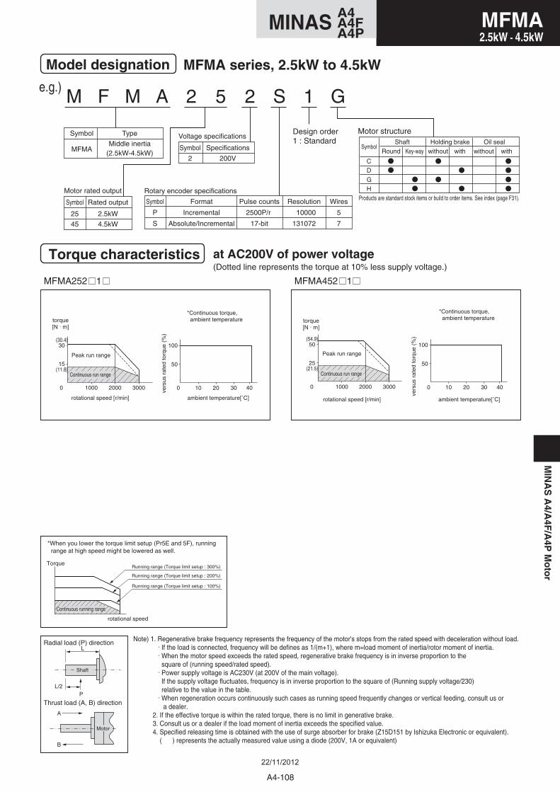
M F M A 2 5 2 S 1 G
Motor structure
Model designation MFMA series, 2.5kW to 4.5kW
Symbol
MFMA
Type
Middle inertia(2.5kW-4.5kW)
Symbol
25
45
Rated output
2.5kW
4.5kW
Symbol
P
S
Format
Incremental
Absolute/Incremental
Pulse counts
2500P/r
17-bit
Resolution
10000
131072
Wires
5
7
Rotary encoder specificationsMotor rated output
Symbol
2
Specifications
200V
Voltage specificationsDesign order1 : Standard
Torque characteristics at AC200V of power voltage(Dotted line represents the torque at 10% less supply voltage.)
e.g.)
MFMA252 1 MFMA452 1
15
0
30
1000 2000 3000
50
0 10 20 30 40
100
25
0
50
1000 2000 3000
50
0 10 20 30 40
100(30.4)
(11.8)
(54.9)
(21.5)
torque[N . m]
Peak run range
rotational speed [r/min] ambient temperature[˚C]
*Continuous torque, ambient temperature
vers
us r
ated
torq
ue (
%)
Continuous run range
torque[N . m]
Peak run range
rotational speed [r/min] ambient temperature[˚C]
*Continuous torque, ambient temperature
vers
us r
ated
torq
ue (
%)
Continuous run range
Note) 1. Regenerative brake frequency represents the frequency of the motor's stops from the rated speed with deceleration without load. . If the load is connected, frequency will be defines as 1/(m+1), where m=load moment of inertia/rotor moment of inertia. . When the motor speed exceeds the rated speed, regenerative brake frequency is in inverse proportion to the square of (running speed/rated speed). . Power supply voltage is AC230V (at 200V of the main voltage). If the supply voltage fluctuates, frequency is in inverse proportion to the square of (Running supply voltage/230) relative to the value in the table. . When regeneration occurs continuously such cases as running speed frequently changes or vertical feeding, consult us or a dealer. 2. If the effective torque is within the rated torque, there is no limit in generative brake. 3. Consult us or a dealer if the load moment of inertia exceeds the specified value. 4. Specified releasing time is obtained with the use of surge absorber for brake (Z15D151 by Ishizuka Electronic or equivalent). ( ) represents the actually measured value using a diode (200V, 1A or equivalent)
A
B
Thrust load (A, B) direction
Radial load (P) directionL
L/2P
Shaft
Motor
*When you lower the torque limit setup (Pr5E and 5F), running range at high speed might be lowered as well.
Torque
rotational speed
Continuous running range
Running range (Torque limit setup : 300%)
Running range (Torque limit setup : 200%)
Running range (Torque limit setup : 100%)
GH
CD
Holding brake
with
Oil sealSymbol
Shaft
without withwithoutRound Key-way
Products are standard stock items or build to order items. See index (page F31).
MIN
AS
A4/A
4F/A
4PM
oto
r
A4-108
MFMA2.5kW - 4.5kW
A4MINAS A4FA4P
22/11/2012
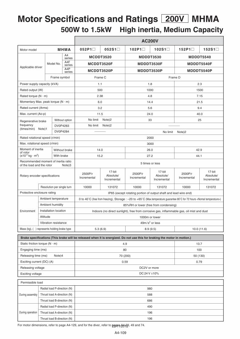
052P1 052S1 102P1 102S1 152P1 152S1
14.0
15.2
26.0
27.2
42.9
44.1
1.1
500
2.38
6.0
3.2
11.5
No limit Note)2
No limit Note)2
2.3
1500
7.15
21.5
9.4
40.0
25
1.8
1000
4.8
14.4
5.6
24.0
33Without option
DV0P4283
DV0P4284
MHMA
2000
3000
13107210000 13107210000 10000 131072
5.3 (6.9)
13.7
100
50 (130)
0.79
4.9
80
70 (200)
0.59
980
588
686
490
196
196
8.9 (9.5) 10.0 (11.6)
MDDDT5540
Frame D
MDDDT3530MCDDT3520
MDDDT5540PMDDDT3530PMCDDT3520P
Frame C
49m/s2 or less
5 times or less
IP65 (except rotating portion of output shaft and lead wire end)
0 to 40˚C (free from freezing), Storage : –20 to +65˚C (Max.temperature guarantee 80˚C for 72 hours <Nomal temperature>)
85%RH or lower (free from condensing)
Indoors (no direct sunlight), free from corrosive gas, inflammable gas, oil mist and dust
1000m or lower
DC2V or more
DC 24 V ±10%
Motor Specifications and Ratings 200V MHMA500W to 1.5kW High inertia, Medium Capacity
AC200V
For motor dimensions, refer to page A4-129, and for the diver, refer to pages A4-23, 49 and 74.
During assembly
During operation
Environment
Radial load P-direction (N)
Thrust load A-direction (N)
Thrust load B-direction (N)
Radial load P-direction (N)
Thrust load A-direction (N)
Thrust load B-direction (N)
Permissible load
Brake specifications (This brake will be released when it is energized. Do not use this for braking the motor in motion.)
Static friction torque (N . m)
Engaging time (ms)
Releasing time (ms) Note)4
Exciting current (DC) (A)
Releasing voltage
Exciting voltage
2500P/r Incremental
2500P/r Incremental
2500P/r Incremental
17-bit Absolute/
Incremental
17-bit Absolute/
Incremental
17-bit Absolute/
Incremental
Protective enclosure rating
Ambient temperature
Ambient humidity
Installation location
Altitude
Vibration resistance
Mass (kg), ( ) represents holding brake type
Rated rotational speed (r/min)
Max. rotational speed (r/min)
Power supply capacity (kVA)
Rated output (W)
Rated torque (N . m)
Momentary Max. peak torque (N . m)
Rated current (Arms)
Max. current (Ao-p)
Motor model
Applicable driver
Resolution per single turn
Moment of inertiaof rotor(x10-4 kg . m2)
Recommended moment of inertia ratioof the load and the rotor Note)3
Without brake
With brake
Regenerative brakefrequency (times/min) Note)1
No limit Note)2
Rotary encoder specifications
Model No.
Frame symbol
A4series
MDDDT5540FMDDDT3530FMCDDT3520FA4FseriesA4Pseries
A4-109
22/11/2012
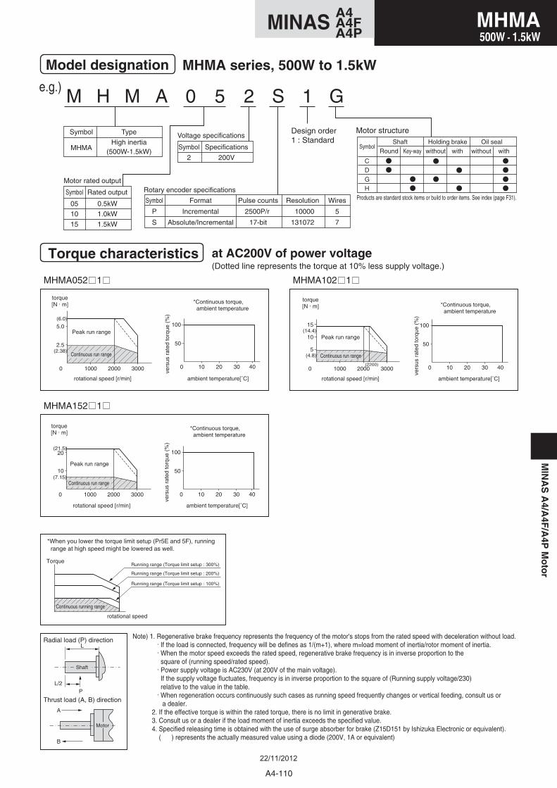
M H M A 0 5 2 S 1 G
Motor structure
Model designation MHMA series, 500W to 1.5kW
Symbol
MHMA
Type
High inertia(500W-1.5kW)
Symbol
05
10
15
Rated output
0.5kW
1.0kW
1.5kW
Symbol
P
S
Format
Incremental
Absolute/Incremental
Pulse counts
2500P/r
17-bit
Resolution
10000
131072
Wires
5
7
Rotary encoder specificationsMotor rated output
Symbol
2
Specifications
200V
Voltage specificationsDesign order1 : Standard
Torque characteristics at AC200V of power voltage(Dotted line represents the torque at 10% less supply voltage.)
e.g.)
MHMA052 1 MHMA102 1
MHMA152 1
2.5
0
5.0
1000 2000 3000
50
0 10 20 30 40
100
0 1000 2000(2200)
3000
5
10
15
50
0 10 20 30 40
100
10
0
20
1000 2000 3000
50
0 10 20 30 40
100
(6.0)
(21.5)
(7.15)
(2.38)
(14.4)
(4.8)
torque[N . m]
Peak run range
rotational speed [r/min] ambient temperature[˚C]
*Continuous torque, ambient temperature
vers
us r
ated
torq
ue (
%)
Continuous run range
torque[N . m]
Peak run range
rotational speed [r/min] ambient temperature[˚C]
*Continuous torque, ambient temperature
vers
us r
ated
torq
ue (
%)
Continuous run range
torque[N . m]
Peak run range
rotational speed [r/min] ambient temperature[˚C]
*Continuous torque, ambient temperature
vers
us r
ated
torq
ue (
%)
Continuous run range
Note) 1. Regenerative brake frequency represents the frequency of the motor's stops from the rated speed with deceleration without load. . If the load is connected, frequency will be defines as 1/(m+1), where m=load moment of inertia/rotor moment of inertia. . When the motor speed exceeds the rated speed, regenerative brake frequency is in inverse proportion to the square of (running speed/rated speed). . Power supply voltage is AC230V (at 200V of the main voltage). If the supply voltage fluctuates, frequency is in inverse proportion to the square of (Running supply voltage/230) relative to the value in the table. . When regeneration occurs continuously such cases as running speed frequently changes or vertical feeding, consult us or a dealer. 2. If the effective torque is within the rated torque, there is no limit in generative brake. 3. Consult us or a dealer if the load moment of inertia exceeds the specified value. 4. Specified releasing time is obtained with the use of surge absorber for brake (Z15D151 by Ishizuka Electronic or equivalent). ( ) represents the actually measured value using a diode (200V, 1A or equivalent)
A
B
Thrust load (A, B) direction
Radial load (P) directionL
L/2P
Shaft
Motor
*When you lower the torque limit setup (Pr5E and 5F), running range at high speed might be lowered as well.
Torque
rotational speed
Continuous running range
Running range (Torque limit setup : 300%)
Running range (Torque limit setup : 200%)
Running range (Torque limit setup : 100%)
GH
CD
Holding brake
with
Oil sealSymbol
Shaft
without withwithoutRound Key-way
Products are standard stock items or build to order items. See index (page F31).
MIN
AS
A4/A
4F/A
4PM
oto
r
A4-110
MHMA500W - 1.5kW
A4MINAS A4FA4P
22/11/2012
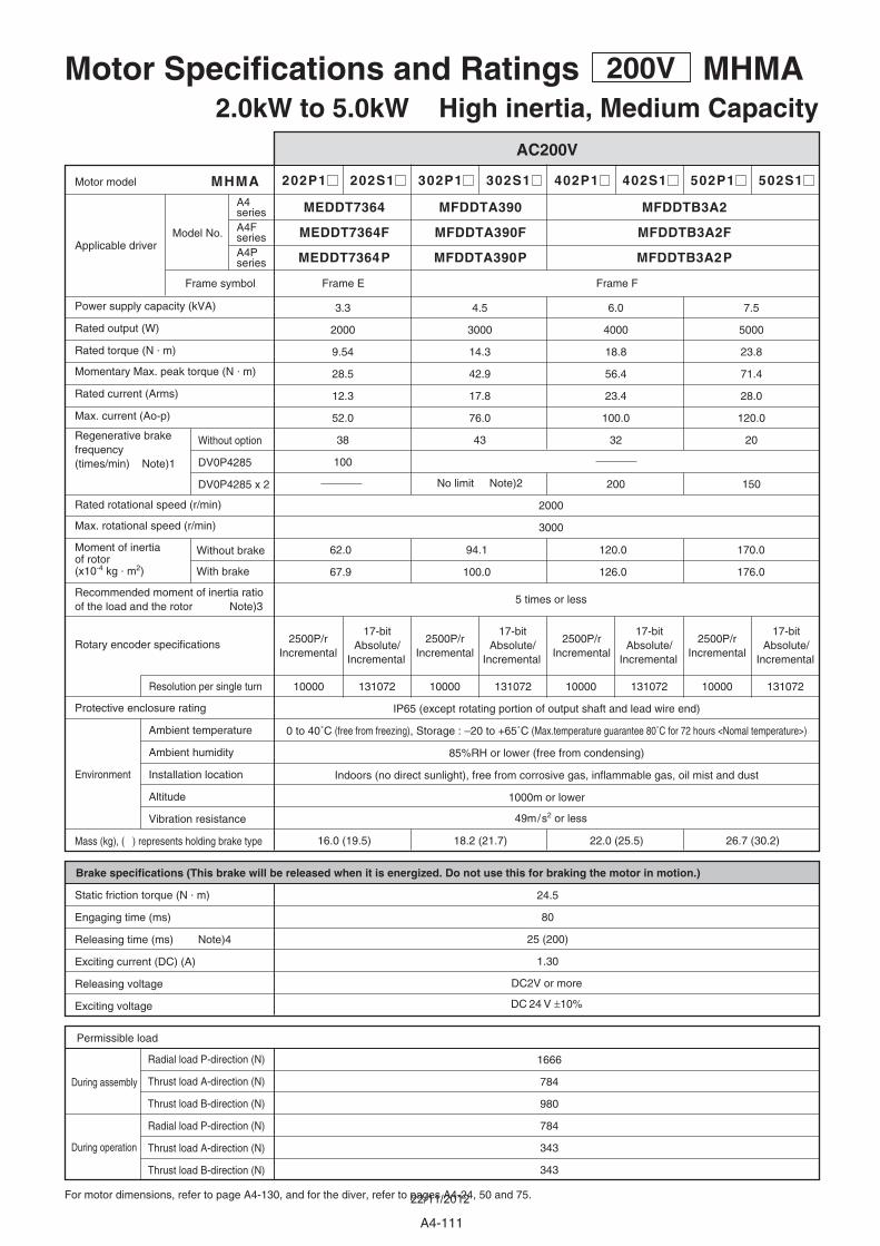
202P1 202S1 302P1 302S1 402P1 402S1 502P1 502S1
62.0
67.9
94.1
100.0
120.0
126.0
170.0
176.0
3.3
2000
9.54
28.5
12.3
52.0
38
100
6.0
4000
18.8
56.4
23.4
100.0
32
200
7.5
5000
23.8
71.4
28.0
120.0
20
150
4.5
3000
14.3
42.9
17.8
76.0
43
No limit Note)2
Without option
DV0P4285
DV0P4285 x 2
MHMA
2000
3000
10000 131072 10000 131072 10000 131072 10000 131072
16.0 (19.5) 18.2 (21.7) 22.0 (25.5) 26.7 (30.2)
24.5
80
25 (200)
1.30
1666
784
980
784
343
343
MFDDTB3A2MEDDT7364 MFDDTA390
MFDDTB3A2PMEDDT7364P MFDDTA390P
Frame FFrame E
49m/s2 or less
5 times or less
IP65 (except rotating portion of output shaft and lead wire end)
0 to 40˚C (free from freezing), Storage : –20 to +65˚C (Max.temperature guarantee 80˚C for 72 hours <Nomal temperature>)
85%RH or lower (free from condensing)
Indoors (no direct sunlight), free from corrosive gas, inflammable gas, oil mist and dust
1000m or lower
DC2V or more
DC 24 V ±10%
Motor Specifications and Ratings 200V MHMA2.0kW to 5.0kW High inertia, Medium Capacity
AC200V
For motor dimensions, refer to page A4-130, and for the diver, refer to pages A4-24, 50 and 75.
During assembly
During operation
Environment
Radial load P-direction (N)
Thrust load A-direction (N)
Thrust load B-direction (N)
Radial load P-direction (N)
Thrust load A-direction (N)
Thrust load B-direction (N)
Permissible load
Brake specifications (This brake will be released when it is energized. Do not use this for braking the motor in motion.)
Static friction torque (N . m)
Engaging time (ms)
Releasing time (ms) Note)4
Exciting current (DC) (A)
Releasing voltage
Exciting voltage
2500P/r Incremental
2500P/r Incremental
2500P/r Incremental
2500P/r Incremental
17-bit Absolute/
Incremental
17-bit Absolute/
Incremental
17-bit Absolute/
Incremental
17-bit Absolute/
Incremental
Protective enclosure rating
Ambient temperature
Ambient humidity
Installation location
Altitude
Vibration resistance
Mass (kg), ( ) represents holding brake type
Rated rotational speed (r/min)
Max. rotational speed (r/min)
Power supply capacity (kVA)
Rated output (W)
Rated torque (N . m)
Momentary Max. peak torque (N . m)
Rated current (Arms)
Max. current (Ao-p)
Motor model
Applicable driver
Resolution per single turn
Moment of inertiaof rotor(x10-4 kg . m2)
Recommended moment of inertia ratioof the load and the rotor Note)3
Without brake
With brake
Regenerative brakefrequency (times/min) Note)1
Rotary encoder specifications
Model No.
Frame symbol
A4series
MFDDTB3A2FMEDDT7364F MFDDTA390FA4FseriesA4Pseries
A4-111
22/11/2012
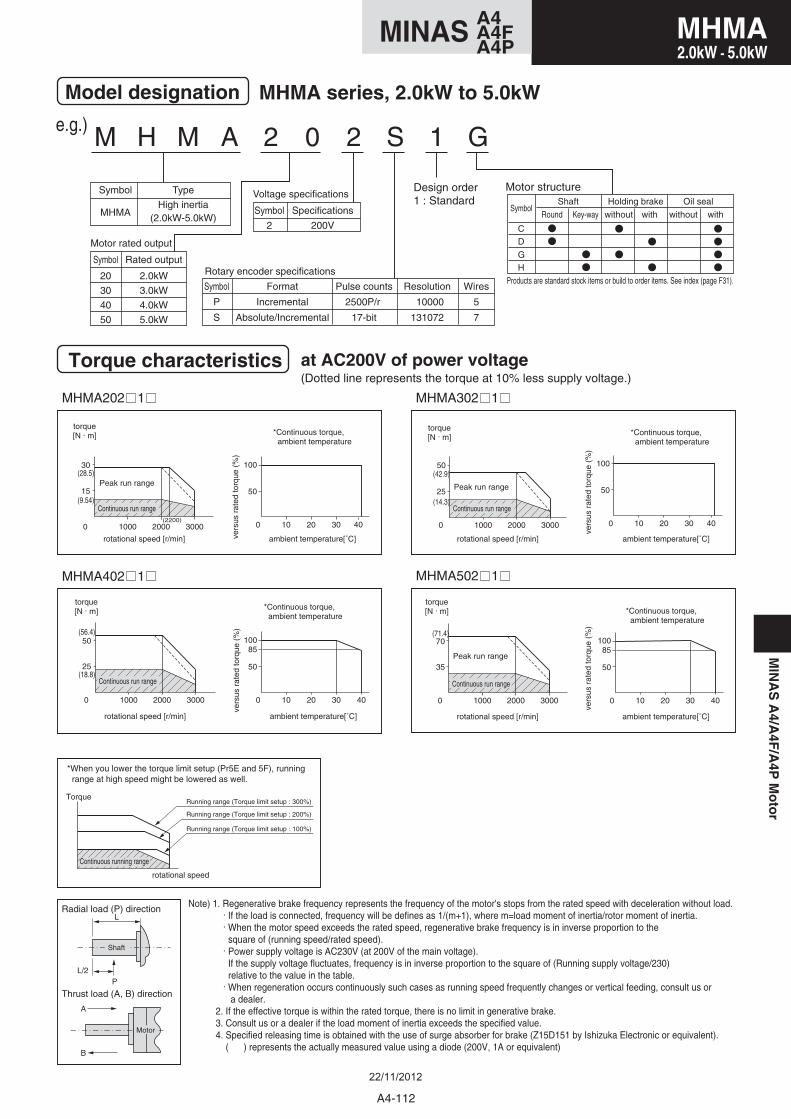
M H M A 2 0 2 S 1 G
Symbol
20
30
40
50
Rated output
2.0kW
3.0kW
4.0kW
5.0kW
Motor structure
Model designation MHMA series, 2.0kW to 5.0kW
Symbol
MHMA
Type
High inertia(2.0kW-5.0kW)
Symbol
P
S
Format
Incremental
Absolute/Incremental
Pulse counts
2500P/r
17-bit
Resolution
10000
131072
Wires
5
7
Rotary encoder specifications
Motor rated output
Symbol
2
Specifications
200V
Voltage specificationsDesign order1 : Standard
Torque characteristics at AC200V of power voltage(Dotted line represents the torque at 10% less supply voltage.)
e.g.)
MHMA202 1 MHMA302 1
MHMA502 1 MHMA402 1
15
0
30
1000 2000 3000(2200)
50
0 10 20 30 40
100
25
0
50
1000 2000 3000
50
0 10 20 30 40
100
25
0
50
1000 2000 3000
85
50
0 10 20 30 40
100
35
0
70
1000 2000 3000
85
50
0 10 20 30 40
100
(28.5)
(56.4)
(18.8)
(9.54)
(42.9)
(14.3)
(71.4)
torque[N . m]
Peak run range
rotational speed [r/min] ambient temperature[˚C]
*Continuous torque, ambient temperature
vers
us r
ated
torq
ue (
%)
Continuous run range
torque[N . m]
rotational speed [r/min] ambient temperature[˚C]
*Continuous torque, ambient temperature
vers
us r
ated
torq
ue (
%)
Continuous run range
torque[N . m]
Peak run range
rotational speed [r/min] ambient temperature[˚C]
*Continuous torque, ambient temperature
vers
us r
ated
torq
ue (
%)
Continuous run range
torque[N . m]
Peak run range
rotational speed [r/min] ambient temperature[˚C]
*Continuous torque, ambient temperature
vers
us r
ated
torq
ue (
%)
Continuous run range
Note) 1. Regenerative brake frequency represents the frequency of the motor's stops from the rated speed with deceleration without load. . If the load is connected, frequency will be defines as 1/(m+1), where m=load moment of inertia/rotor moment of inertia. . When the motor speed exceeds the rated speed, regenerative brake frequency is in inverse proportion to the square of (running speed/rated speed). . Power supply voltage is AC230V (at 200V of the main voltage). If the supply voltage fluctuates, frequency is in inverse proportion to the square of (Running supply voltage/230) relative to the value in the table. . When regeneration occurs continuously such cases as running speed frequently changes or vertical feeding, consult us or a dealer. 2. If the effective torque is within the rated torque, there is no limit in generative brake. 3. Consult us or a dealer if the load moment of inertia exceeds the specified value. 4. Specified releasing time is obtained with the use of surge absorber for brake (Z15D151 by Ishizuka Electronic or equivalent). ( ) represents the actually measured value using a diode (200V, 1A or equivalent)
A
B
Thrust load (A, B) direction
Radial load (P) directionL
L/2P
Shaft
Motor
*When you lower the torque limit setup (Pr5E and 5F), running range at high speed might be lowered as well.
Torque
rotational speed
Continuous running range
Running range (Torque limit setup : 300%)
Running range (Torque limit setup : 200%)
Running range (Torque limit setup : 100%)
GH
CD
Holding brake
with
Oil sealSymbol
Shaft
without withwithoutRound Key-way
Products are standard stock items or build to order items. See index (page F31).
MIN
AS
A4/A
4F/A
4PM
oto
r
A4-112
MHMA2.0kW - 5.0kW
A4MINAS A4FA4P
22/11/2012
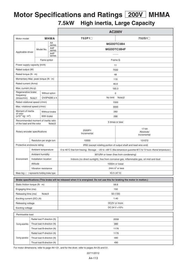
752P1
282
288
11
7500
48
119
46.6
165.0
0Without option
DV0P4285 x 4
MHMA
1500
3000
10000 131072
43.5 (47.5)
58.8
150
50 (130)
1.40
2058
980
1176
1176
490
490
752S1
MGDDTC3B4
Frame G
24m/s2 or less
5 times or less
IP65 (except rotating portion of output shaft and lead wire end)
0 to 40˚C (free from freezing), Storage : –20 to +65˚C (Max.temperature guarantee 80˚C for 72 hours <Nomal temperature>)
85%RH or lower (free from condensing)
Indoors (no direct sunlight), free from corrosive gas, inflammable gas, oil mist and dust
1000m or lower
DC2V or more
DC 24 V ±10%
Motor Specifications and Ratings 200V MHMA7.5kW High inertia, Large Capacity
AC200V
For motor dimensions, refer to page A4-131, and for the diver, refer to pages A4-25 and 51.
During assembly
During operation
Environment
Radial load P-direction (N)
Thrust load A-direction (N)
Thrust load B-direction (N)
Radial load P-direction (N)
Thrust load A-direction (N)
Thrust load B-direction (N)
Permissible load
Brake specifications (This brake will be released when it is energized. Do not use this for braking the motor in motion.)
Static friction torque (N . m)
Engaging time (ms)
Releasing time (ms) Note)4
Exciting current (DC) (A)
Releasing voltage
Exciting voltage
2500P/r Incremental
17-bit Absolute/
Incremental
Protective enclosure rating
Ambient temperature
Ambient humidity
Installation location
Altitude
Vibration resistance
Mass (kg), ( ) represents holding brake type
Rated rotational speed (r/min)
Max. rotational speed (r/min)
Power supply capacity (kVA)
Rated output (W)
Rated torque (N . m)
Momentary Max. peak torque (N . m)
Rated current (Arms)
Max. current (Ao-p)
Motor model
Applicable driver
Resolution per single turn
Moment of inertiaof rotor(x10-4 kg . m2)
Recommended moment of inertia ratioof the load and the rotor Note)3
Without brake
With brake
Regenerative brakefrequency (times/min) Note)1 No limit Note)2
Rotary encoder specifications
Model No.
Frame symbol
A4series
MGDDTC3B4FA4FseriesA4Pseries
A4-113
22/11/2012
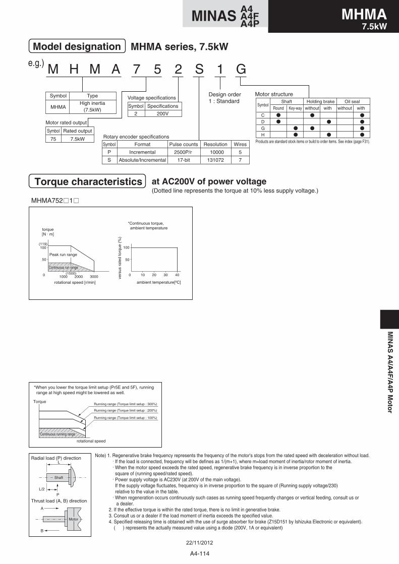
M H M A 7 5 2 S 1 G
Symbol
75
Rated output
7.5kW
Motor structure
Model designation MHMA series, 7.5kW
Symbol
MHMA
Type
High inertia(7.5kW)
Symbol
P
S
Format
Incremental
Absolute/Incremental
Pulse counts
2500P/r
17-bit
Resolution
10000
131072
Wires
5
7
Rotary encoder specifications
Motor rated output
Symbol
2
Specifications
200V
Voltage specificationsDesign order1 : Standard
Torque characteristics at AC200V of power voltage(Dotted line represents the torque at 10% less supply voltage.)
e.g.)
MHMA752 1
Note) 1. Regenerative brake frequency represents the frequency of the motor's stops from the rated speed with deceleration without load. . If the load is connected, frequency will be defines as 1/(m+1), where m=load moment of inertia/rotor moment of inertia. . When the motor speed exceeds the rated speed, regenerative brake frequency is in inverse proportion to the square of (running speed/rated speed). . Power supply voltage is AC230V (at 200V of the main voltage). If the supply voltage fluctuates, frequency is in inverse proportion to the square of (Running supply voltage/230) relative to the value in the table. . When regeneration occurs continuously such cases as running speed frequently changes or vertical feeding, consult us or a dealer. 2. If the effective torque is within the rated torque, there is no limit in generative brake. 3. Consult us or a dealer if the load moment of inertia exceeds the specified value. 4. Specified releasing time is obtained with the use of surge absorber for brake (Z15D151 by Ishizuka Electronic or equivalent). ( ) represents the actually measured value using a diode (200V, 1A or equivalent)
A
B
Thrust load (A, B) direction
Radial load (P) directionL
L/2P
Shaft
Motor
*When you lower the torque limit setup (Pr5E and 5F), running range at high speed might be lowered as well.
Torque
rotational speed
Continuous running range
Running range (Torque limit setup : 300%)
Running range (Torque limit setup : 200%)
Running range (Torque limit setup : 100%)
GH
CD
Holding brake
with
Oil sealSymbol
Shaft
without withwithoutRound Key-way
Products are standard stock items or build to order items. See index (page F31).
50
0
100(119)
1000(1500)
2000 3000
50
0 10 20 30 40
100
torque[N . m]
rotational speed [r/min] ambient temperature[ºC]
*Continuous torque, ambient temperature
vers
us r
ated
torq
ue (
%)
Peak run range
Continuous run range
A4-114
MHMA7.5kW
A4MINAS A4FA4P
MIN
AS
A4/A
4F/A
4PM
oto
r
22/11/2012
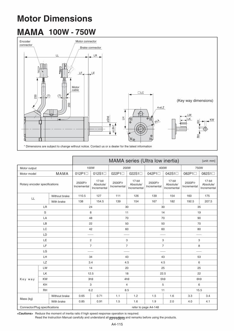
A4-115
MAMA 100W - 750W
MAMA series (Ultra low inertia)
012P1 012S1 022P1 022S1 042P1 042S1 082P1 082S1
17-bit Absolute/
Incremental
2500P/rIncremental
17-bit Absolute/
Incremental
2500P/rIncremental
17-bit Absolute/
Incremental
2500P/rIncremental
17-bit Absolute/
Incremental
2500P/rIncremental
MAMA
100W 200W 400W 750W
Motor model
Rotary encoder specifications
K e y w a y
Motor output
Mass (kg)
Connector/Plug specifications refer to page A4-148
Without brake
With brake
Without brake
With brake
LL110.5
138
127
154.5
111
139
126
154
139
167
154
182
160
192.5
175
207.5
24
8
48
22
42
2
7
34
3.4
14
12.5
3h9
3
6.2
0.65
0.85
0.71
0.91
1.1
1.5
1.2
1.6
1.5
1.9
1.6
2.0
3.3
4.0
3.4
4.1
LR
S
LA
LB
LC
LD
LE
LF
LG
LH
LZ
LW
LK
KW
KH
RH
30
11
70
50
60
3
7
43
4.5
20
18
4h9
4
8.5
30
14
70
50
60
3
7
43
4.5
25
22.5
5h9
5
11
35
19
90
70
80
3
8
53
6
25
22
6h9
6
15.5
<Cautions> Reduce the moment of inertia ratio if high speed response operation is required.Read the Instruction Manual carefully and understand all precautions and remarks before using the products.
* Dimensions are subject to change without notice. Contact us or a dealer for the latest information
[unit: mm]
Motor connectorEncoderconnector
Brake connector
(Key way dimensions)
Motorcable
øLA
LC
LH
4-øLZ
230
200
LELF
LL
øSh6
øLB
h7
LR
LKLW
KW
RH
(7) (7)
KH
Motor Dimensions
22/11/2012
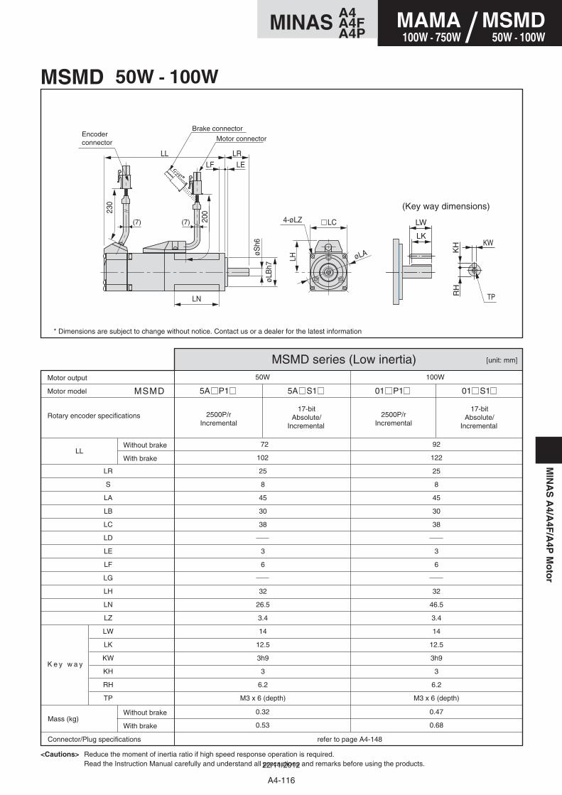
MIN
AS
A4/A
4F/A
4PM
oto
r
[unit: mm]
5A P1 5A S1 01 P1 01 S1 MSMD
50W 100W
LL
25
8
45
30
38
3
6
32
26.5
3.4
14
12.5
3h9
3
6.2
M3 x 6 (depth)
25
8
45
30
38
3
6
32
46.5
3.4
14
12.5
3h9
3
6.2
M3 x 6 (depth)
0.32
0.53
0.47
0.68
72
102
92
122
LR
S
LA
LB
LC
LD
LE
LF
LG
LH
LN
LZ
LW
LK
KW
KH
RH
TP
MSMD 50W - 100W
MSMD series (Low inertia)
17-bit Absolute/
Incremental
17-bit Absolute/
Incremental
2500P/rIncremental
2500P/rIncremental
Motor model
Motor output
Mass (kg)
Connector/Plug specifications refer to page A4-148
Without brake
With brake
Without brake
With brake
<Cautions> Reduce the moment of inertia ratio if high speed response operation is required.Read the Instruction Manual carefully and understand all precautions and remarks before using the products.
* Dimensions are subject to change without notice. Contact us or a dealer for the latest information
Rotary encoder specifications
K e y w a y
Motor connectorEncoderconnector
Brake connector
(Key way dimensions)230
200
LELFLL LR
øSh6
øLB
h7
LH
LC
LN
øLA
LW
KW
TP
KH
RH
LK
4-øLZ(7)(7)
A4-116
MAMA100W - 750W
MSMD50W - 100W/
A4MINAS A4FA4P
22/11/2012
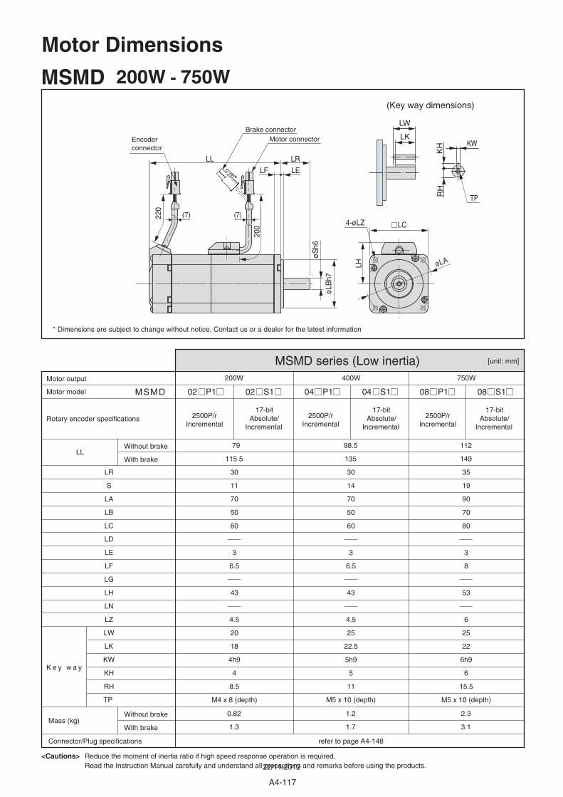
A4-117
02 P1 02 S1 04 P1 04 S1 08 P1 08 S1
200W 400W 750W
79
115.5
30
11
70
50
60
3
6.5
43
4.5
20
18
4h9
4
8.5
M4 x 8 (depth)
30
14
70
50
60
3
6.5
43
4.5
25
22.5
5h9
5
11
M5 x 10 (depth)
35
19
90
70
80
3
8
53
6
25
22
6h9
6
15.5
M5 x 10 (depth)
0.82
1.3
1.2
1.7
2.3
3.1
98.5
135
112
149
[unit: mm]
MSMD
LL
LR
S
LA
LB
LC
LD
LE
LF
LG
LH
LN
LZ
LW
LK
KW
KH
RH
TP
MSMD 200W - 750W
MSMD series (Low inertia)
17-bit Absolute/
Incremental
17-bit Absolute/
Incremental
17-bit Absolute/
Incremental
2500P/rIncremental
2500P/rIncremental
2500P/rIncremental
Motor model
Rotary encoder specifications
K e y w a y
Motor output
Mass (kg)
Connector/Plug specifications refer to page A4-148
Without brake
With brake
Without brake
With brake
<Cautions> Reduce the moment of inertia ratio if high speed response operation is required.Read the Instruction Manual carefully and understand all precautions and remarks before using the products.
* Dimensions are subject to change without notice. Contact us or a dealer for the latest information
220
200
LELF
LL LR
øSh6
øLB
h7
LH
LC
øLA
LW
KW
TP
KH
RH
LK
4-øLZ
Motor connectorEncoderconnector
Brake connector
(Key way dimensions)
Motor Dimensions
(7) (7)
22/11/2012
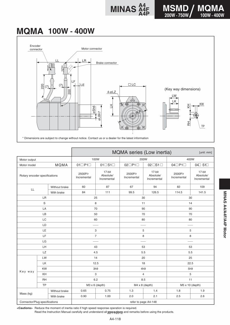
MIN
AS
A4/A
4F/A
4PM
oto
r
01 P1 01 S1 02 P1 02 S1 04 P1 04 S1
100W 200W 400W
60
84
25
8
70
50
60
3
7
43
4.5
14
12.5
3h9
3
6.2
M3 x 6 (depth)
30
11
90
70
80
5
8
53
5.5
20
18
4h9
4
8.5
M4 x 8 (depth)
30
14
90
70
80
5
8
53
5.5
25
22.5
5h9
5
11
M5 x 10 (depth)
87
111
0.65
0.90
0.75
1.00
1.3
2.0
1.4
2.1
1.8
2.5
1.9
2.6
67
99.5
94
126.5
82
114.5
109
141.5
[unit: mm]
MQMA
LL
LR
S
LA
LB
LC
LD
LE
LF
LG
LH
LZ
LW
LK
KW
KH
RH
TP
MQMA 100W - 400W
MQMA series (Low inertia)
17-bit Absolute/
Incremental
17-bit Absolute/
Incremental
17-bit Absolute/
Incremental
2500P/rIncremental
2500P/rIncremental
2500P/rIncremental
Motor model
Rotary encoder specifications
K e y w a y
Motor output
Mass (kg)
Connector/Plug specifications refer to page A4-148
Without brake
With brake
Without brake
With brake
<Cautions> Reduce the moment of inertia ratio if high speed response operation is required.Read the Instruction Manual carefully and understand all precautions and remarks before using the products.
* Dimensions are subject to change without notice. Contact us or a dealer for the latest information
Motor connectorEncoderconnector
Brake connector
(Key way dimensions)
LL LR
LELF
20022
0
øLB
h7
LH
øS
h6
LC
øLA
4-øLZ
(7) (7)
LW
KW
TP
KH
RH
LK
A4-118
MSMD200W - 750W
MQMA100W - 400W/
A4MINAS A4FA4P
22/11/2012
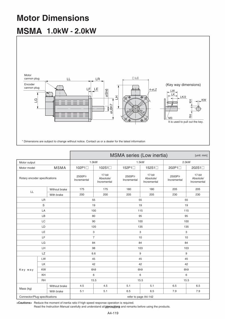
[unit: mm]
102P1 102S1 152P1 152S1 202P1 202S1 MSMA
1.0kW 1.5kW 2.0kW
LL175
200
55
19
100
80
90
120
3
7
84
98
6.6
45
42
6h9
6
15.5
55
19
115
95
100
135
3
10
84
103
9
45
42
6h9
6
15.5
55
19
115
95
100
135
3
10
84
103
9
45
42
6h9
6
15.5
175
200
4.5
5.1
4.5
5.1
5.1
6.5
5.1
6.5
6.5
7.9
6.5
7.9
180
205
180
205
205
230
205
230
LR
S
LA
LB
LC
LD
LE
LF
LG
LH
LZ
LW
LK
KW
KH
RH
MSMA 1.0kW - 2.0kW
MSMA series (Low inertia)
17-bit Absolute/
Incremental
17-bit Absolute/
Incremental
17-bit Absolute/
Incremental
2500P/rIncremental
2500P/rIncremental
2500P/rIncremental
Motor model
Rotary encoder specifications
K e y w a y
Motor output
Mass (kg)
Connector/Plug specifications refer to page A4-142
Without brake
With brake
Without brake
With brake
<Cautions> Reduce the moment of inertia ratio if high speed response operation is required.Read the Instruction Manual carefully and understand all precautions and remarks before using the products.
* Dimensions are subject to change without notice. Contact us or a dealer for the latest information
Motor cannon plug
Encoder cannon plug
(Key way dimensions)
LL LR
LF LE
øLB
h7
LH
LG
øS
h6
4-øLZ
LC
øLAøLD
LWLK
KW
KH
RH
LK/2
M3It is used to pull out the key.
Motor Dimensions
A4-119
22/11/2012
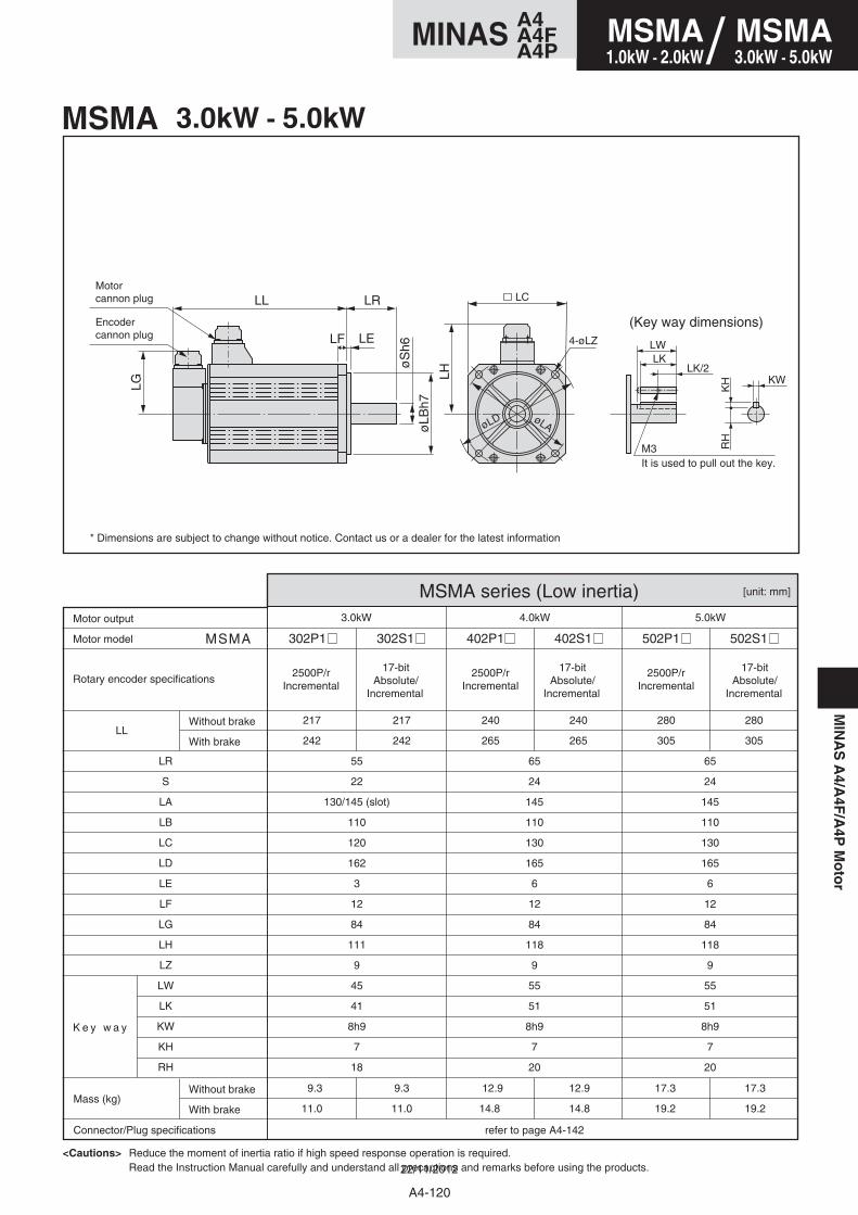
MIN
AS
A4/A
4F/A
4PM
oto
r
302P1 302S1 402P1 402S1 502P1 502S1
3.0kW 4.0kW 5.0kW
217
242
55
22
130/145 (slot)
110
120
162
3
12
84
111
9
45
41
8h9
7
18
65
24
145
110
130
165
6
12
84
118
9
55
51
8h9
7
20
65
24
145
110
130
165
6
12
84
118
9
55
51
8h9
7
20
217
242
9.3
11.0
9.3
11.0
12.9
14.8
12.9
14.8
17.3
19.2
17.3
19.2
240
265
240
265
280
305
280
305
[unit: mm]
MSMA
LL
LR
S
LA
LB
LC
LD
LE
LF
LG
LH
LZ
LW
LK
KW
KH
RH
MSMA 3.0kW - 5.0kW
MSMA series (Low inertia)
17-bit Absolute/
Incremental
17-bit Absolute/
Incremental
17-bit Absolute/
Incremental
2500P/rIncremental
2500P/rIncremental
2500P/rIncremental
Motor model
Rotary encoder specifications
K e y w a y
Motor output
Mass (kg)
Connector/Plug specifications refer to page A4-142
Without brake
With brake
Without brake
With brake
<Cautions> Reduce the moment of inertia ratio if high speed response operation is required.Read the Instruction Manual carefully and understand all precautions and remarks before using the products.
* Dimensions are subject to change without notice. Contact us or a dealer for the latest information
Motor cannon plug
Encoder cannon plug
(Key way dimensions)
LL LR
LF LE
øLB
h7
LH
LG
øS
h6 4-øLZ
LC
øLAøLD
LWLK
KW
KH
RH
LK/2
M3It is used to pull out the key.
A4-120
MSMA3.0kW - 5.0kW
A4MINAS A4FA4P
MSMA1.0kW - 2.0kW/
22/11/2012
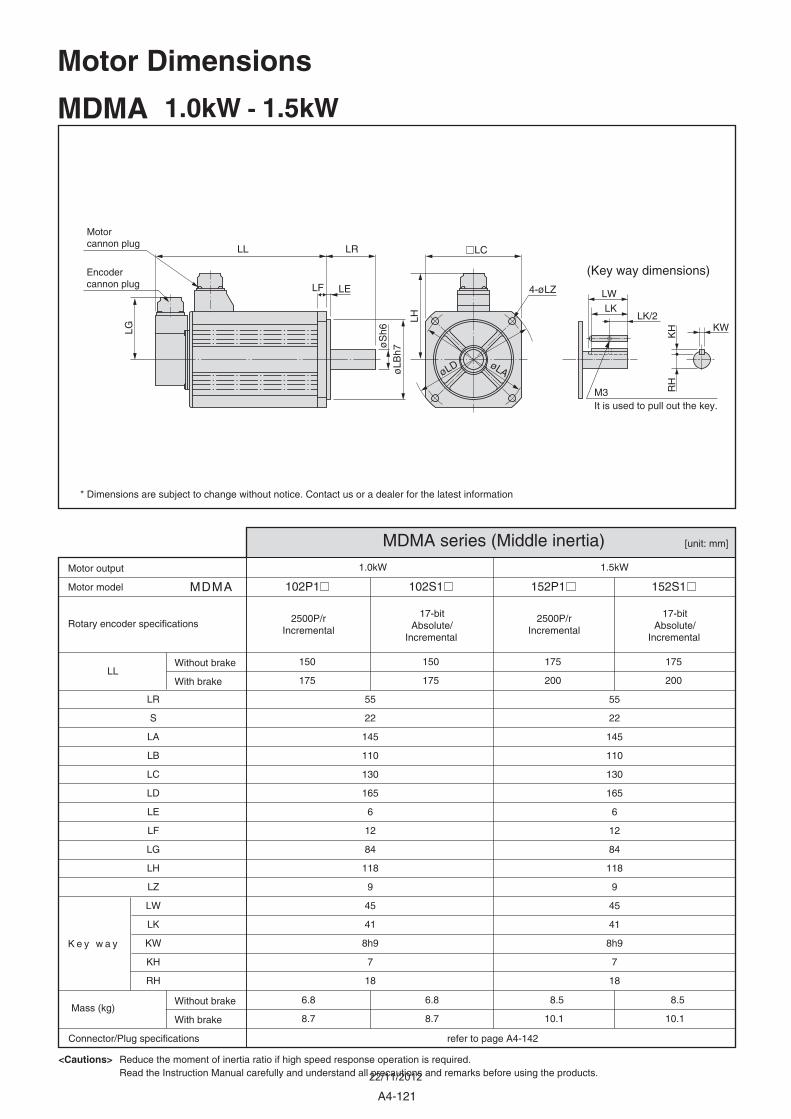
102P1 102S1 152P1 152S1 MDMA
1.0kW 1.5kW
LL
55
22
145
110
130
165
6
12
84
118
9
45
41
8h9
7
18
55
22
145
110
130
165
6
12
84
118
9
45
41
8h9
7
18
6.8
8.7
6.8
8.7
8.5
10.1
8.5
10.1
150
175
150
175
175
200
175
200
LR
S
LA
LB
LC
LD
LE
LF
LG
LH
LZ
LW
LK
KW
KH
RH
MDMA 1.0kW - 1.5kW
MDMA series (Middle inertia)
17-bit Absolute/
Incremental
17-bit Absolute/
Incremental
2500P/rIncremental
2500P/rIncremental
Motor model
Rotary encoder specifications
K e y w a y
Motor output
Mass (kg)
Connector/Plug specifications refer to page A4-142
Without brake
With brake
Without brake
With brake
<Cautions> Reduce the moment of inertia ratio if high speed response operation is required.Read the Instruction Manual carefully and understand all precautions and remarks before using the products.
* Dimensions are subject to change without notice. Contact us or a dealer for the latest information
[unit: mm]
Motor cannon plug
Encoder cannon plug
(Key way dimensions)
LL LR
LF LE
øLB
h7
LH
LG
øS
h6
LC
4-øLZ
øLD øLA
LW
LK
KW
KH
RH
LK/2
M3It is used to pull out the key.
Motor Dimensions
A4-121
22/11/2012
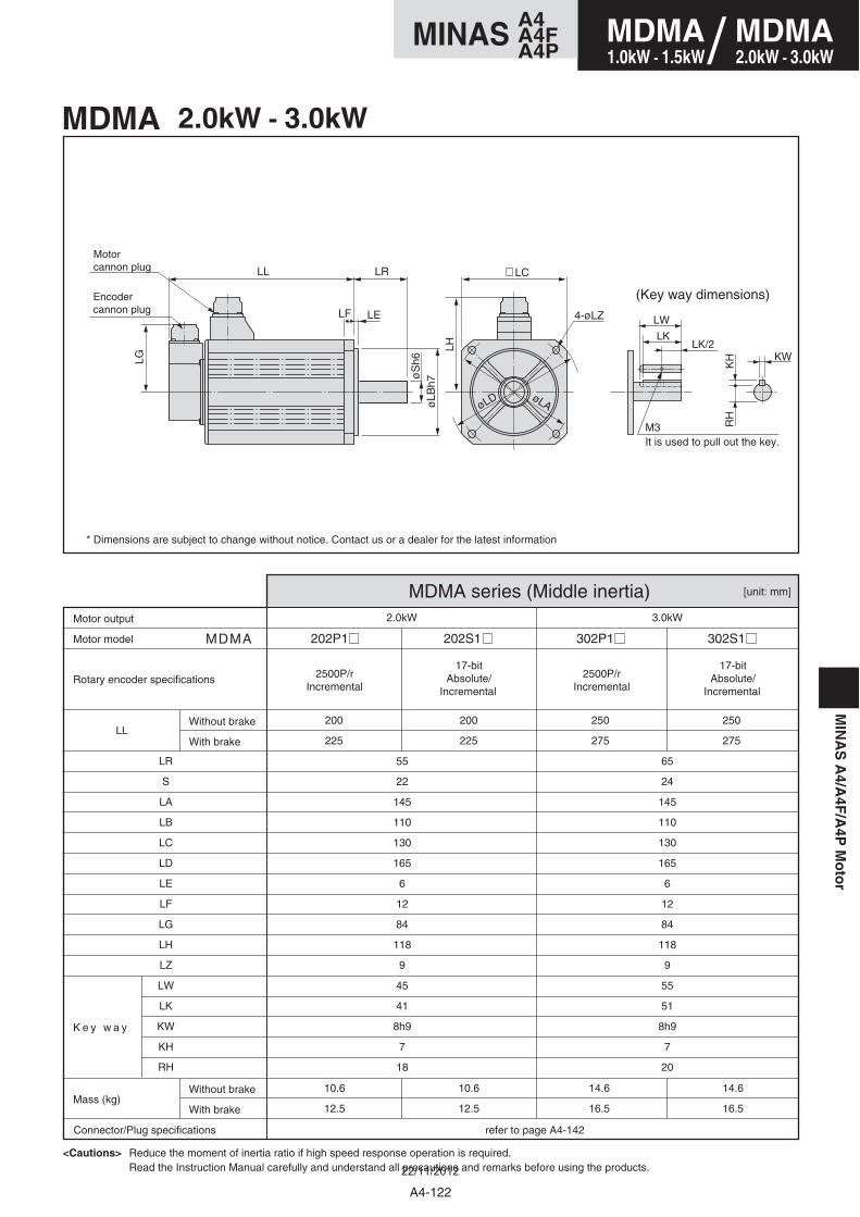
MIN
AS
A4/A
4F/A
4PM
oto
r
202P1 202S1 302P1 302S1
2.0kW 3.0kW
200
225
55
22
145
110
130
165
6
12
84
118
9
45
41
8h9
7
18
65
24
145
110
130
165
6
12
84
118
9
55
51
8h9
7
20
200
225
10.6
12.5
10.6
12.5
14.6
16.5
14.6
16.5
250
275
250
275
[unit: mm]
MDMA
LL
LR
S
LA
LB
LC
LD
LE
LF
LG
LH
LZ
LW
LK
KW
KH
RH
MDMA 2.0kW - 3.0kW
MDMA series (Middle inertia)
17-bit Absolute/
Incremental
17-bit Absolute/
Incremental
2500P/rIncremental
2500P/rIncremental
Motor model
Rotary encoder specifications
K e y w a y
Motor output
Mass (kg)
Connector/Plug specifications refer to page A4-142
Without brake
With brake
Without brake
With brake
<Cautions> Reduce the moment of inertia ratio if high speed response operation is required.Read the Instruction Manual carefully and understand all precautions and remarks before using the products.
* Dimensions are subject to change without notice. Contact us or a dealer for the latest information
Motor cannon plug
Encoder cannon plug
(Key way dimensions)
LL LR
LF LE
øLB
h7
LH
LG
øS
h6
LC
4-øLZ
øLD øLA
LW
LK
KW
KH
RH
LK/2
M3It is used to pull out the key.
A4-122
MDMA2.0kW - 3.0kW
A4MINAS A4FA4P
MDMA1.0kW - 1.5kW/
22/11/2012
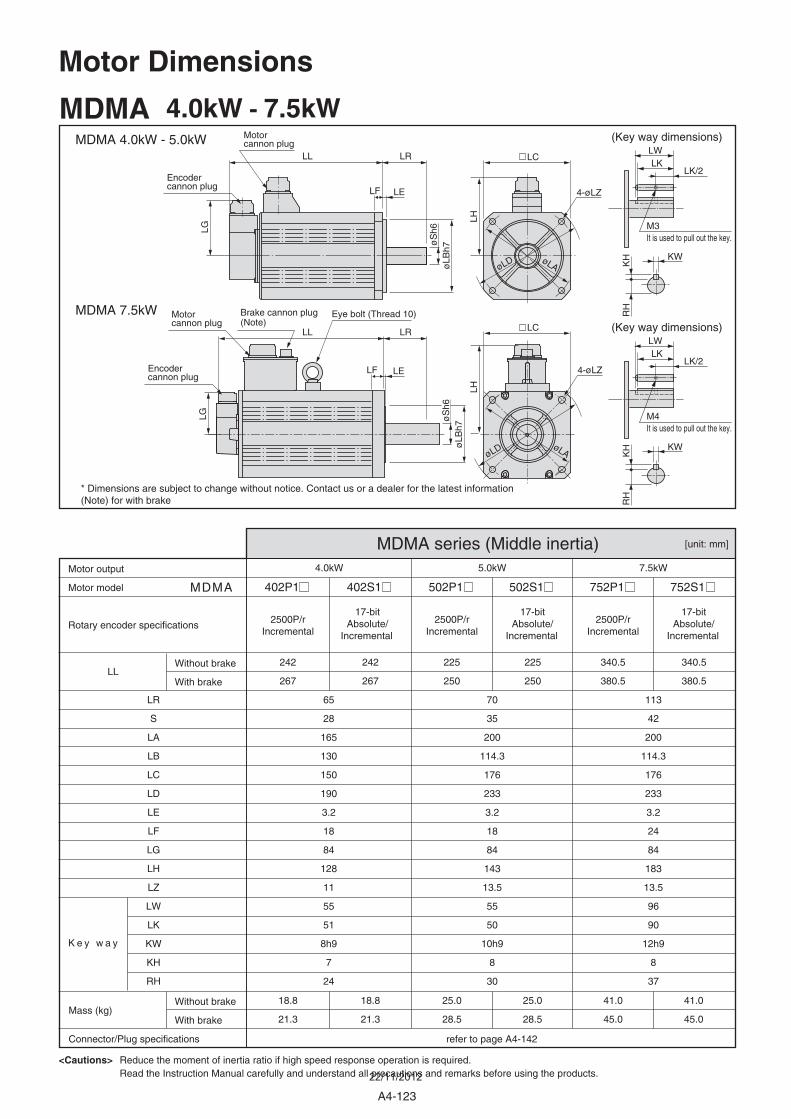
[unit: mm]
402P1 402S1 502P1 502S1 MDMA
4.0kW 5.0kW
LL242
267
242
267
225
250
225
250
65
28
165
130
150
190
3.2
18
84
128
11
55
51
8h9
7
24
70
35
200
114.3
176
233
3.2
18
84
143
13.5
55
50
10h9
8
30
18.8
21.3
18.8
21.3
25.0
28.5
25.0
28.5
LR
S
LA
LB
LC
LD
LE
LF
LG
LH
LZ
LW
LK
KW
KH
RH
MDMA 4.0kW - 7.5kW
MDMA series (Middle inertia)
17-bit Absolute/
Incremental
17-bit Absolute/
Incremental
2500P/rIncremental
2500P/rIncremental
752P1 752S1
7.5kW
340.5
380.5
340.5
380.5
113
42
200
114.3
176
233
3.2
24
84
183
13.5
96
90
12h9
8
37
41.0
45.0
41.0
45.0
17-bit Absolute/
Incremental
2500P/rIncremental
Motor model
Rotary encoder specifications
Motor output
Mass (kg)
Connector/Plug specifications refer to page A4-142
Without brake
With brake
Without brake
With brake
<Cautions> Reduce the moment of inertia ratio if high speed response operation is required.Read the Instruction Manual carefully and understand all precautions and remarks before using the products.
* Dimensions are subject to change without notice. Contact us or a dealer for the latest information (Note) for with brake
K e y w a y
Motor cannon plug
Encoder cannon plug
MDMA 4.0kW - 5.0kW
MDMA 7.5kW
(Key way dimensions)
Brake cannon plug(Note)
Motor cannon plug
Encoder cannon plug
LL LR
LF LE
øLB
h7
LH
LG
øS
h6
LC
LH
LC
4-øLZ
4-øLZ
øLD
øLD
øLA
øLA
LL LR
LF LE
øLB
h7
LG øS
h6
KW
KH
RH
LWLK
LK/2
(Key way dimensions)
KW
KH
RH
LWLK
LK/2
M3It is used to pull out the key.
M4It is used to pull out the key.
Motor Dimensions
Eye bolt (Thread 10)
A4-123
22/11/2012
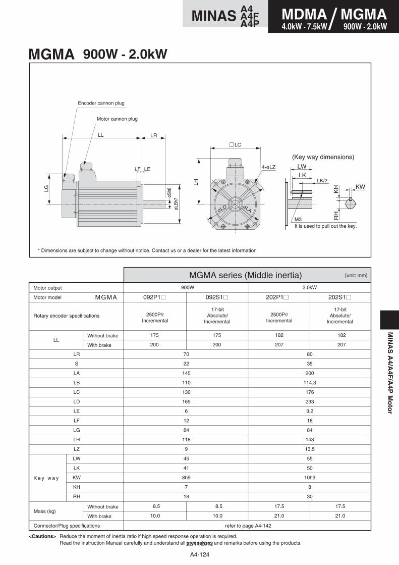
MIN
AS
A4/A
4F/A
4PM
oto
r
[unit: mm]
092P1 092S1 202P1 202S1 MGMA
900W 2.0kW
LL
70
22
145
110
130
165
6
12
84
118
9
45
41
8h9
7
18
80
35
200
114.3
176
233
3.2
18
84
143
13.5
55
50
10h9
8
30
8.5
10.0
8.5
10.0
17.5
21.0
17.5
21.0
175
200
175
200
182
207
182
207
LR
S
LA
LB
LC
LD
LE
LF
LG
LH
LZ
LW
LK
KW
KH
RH
MGMA 900W - 2.0kW
MGMA series (Middle inertia)
17-bit Absolute/
Incremental
17-bit Absolute/
Incremental 2500P/r
Incremental2500P/r
Incremental
Motor model
Rotary encoder specifications
K e y w a y
Motor output
Mass (kg)
Connector/Plug specifications refer to page A4-142
Without brake
With brake
Without brake
With brake
<Cautions> Reduce the moment of inertia ratio if high speed response operation is required.Read the Instruction Manual carefully and understand all precautions and remarks before using the products.
* Dimensions are subject to change without notice. Contact us or a dealer for the latest information
Motor cannon plug
Encoder cannon plug
(Key way dimensions)
4-øLZ
LC
øLAøLD
øSh6
LR
LE
LL
LF
LH
LG
øL B
h7
LW
LK
KW
KH
RH
LK/2
M3It is used to pull out the key.
A4-124
MDMA4.0kW - 7.5kW
MGMA900W - 2.0kW/
A4MINAS A4FA4P
22/11/2012
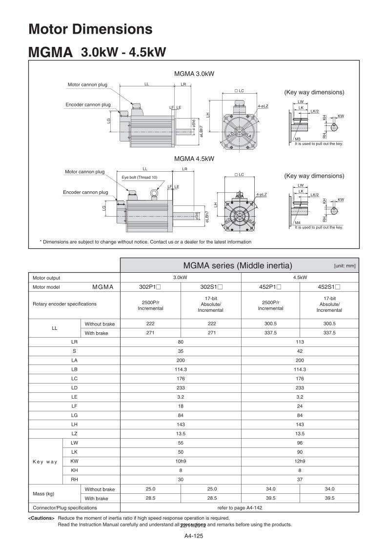
[unit: mm]
302P1 302S1 452P1 452S1 MGMA
3.0kW 4.5kW
LL222
271
222
271
300.5
337.5
300.5
337.5
80
35
200
114.3
176
233
3.2
18
84
143
13.5
55
50
10h9
8
30
113
42
200
114.3
176
233
3.2
24
84
143
13.5
96
90
12h9
8
37
25.0
28.5
25.0
28.5
34.0
39.5
34.0
39.5
LR
S
LA
LB
LC
LD
LE
LF
LG
LH
LZ
LW
LK
KW
KH
RH
MGMA 3.0kW - 4.5kW
MGMA series (Middle inertia)
17-bit Absolute/
Incremental
17-bit Absolute/
Incremental
2500P/rIncremental
2500P/rIncremental
Motor model
Rotary encoder specifications
K e y w a y
Motor output
Mass (kg)
Connector/Plug specifications refer to page A4-142
Without brake
With brake
Without brake
With brake
<Cautions> Reduce the moment of inertia ratio if high speed response operation is required.Read the Instruction Manual carefully and understand all precautions and remarks before using the products.
* Dimensions are subject to change without notice. Contact us or a dealer for the latest information
Eye bolt (Thread 10)
Motor cannon plug
Motor cannon plug
Encoder cannon plug
Encoder cannon plug
4-øLZ
øLAøLD
4-øLZ
LC
LC
øLAøLD
MGMA 3.0kW
MGMA 4.5kW
øSh6
øL
Bh7
øL
Bh7
øSh6
LR
LR
LE
LL
LL
LF
LF
LH
LG
LE
LH
LGLW
LK
KW
KH
RH
LK/2
M3It is used to pull out the key.
LW
LK
KW
KH
RH
M4It is used to pull out the key.
LK/2
(Key way dimensions)
(Key way dimensions)
Motor Dimensions
A4-125
22/11/2012
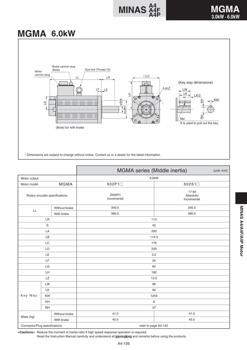
[unit: mm]
602P1 602S1 MGMA
6.0kW
LL
113
42
200
114.3
176
233
3.2
24
84
183
13.5
96
90
12h9
8
37
41.0
45.0
41.0
45.0
340.5
380.5
340.5
380.5
LR
S
LA
LB
LC
LD
LE
LF
LG
LH
LZ
LW
LK
KW
KH
RH
MGMA 6.0kW
MGMA series (Middle inertia)
17-bit Absolute/
Incremental 2500P/r
Incremental
Motor model
Motor output
Mass (kg)
K e y W a y
Connector/Plug specifications refer to page A4-142
Without brake
With brake
Without brake
With brake
<Cautions> Reduce the moment of inertia ratio if high speed response operation is required.Read the Instruction Manual carefully and understand all precautions and remarks before using the products.
Motor cannon plug
(Key way dimensions)
LH
LCLL LR
LF LE
øLB
h7
LG øS
h6
Rotary encoder specifications
LWLK
KW
KH
RH
LK/2
M4It is used to pull out the key.
* Dimensions are subject to change without notice. Contact us or a dealer for the latest information
Brake cannon plug(Note) Eye bolt (Thread 10)
4-øLZ
øLAøLD
(Note) for with brake
A4-126
A4MINAS A4FA4P
MIN
AS
A4/A
4F/A
4PM
oto
rMGMA3.0kW - 6.0kW
22/11/2012
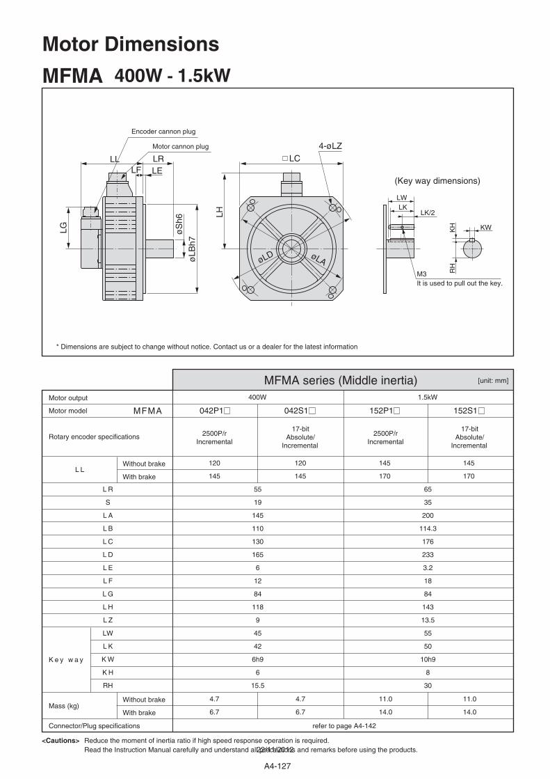
A4-127
[unit: mm]
042P1 042S1 152P1 152S1 MFMA
400W 1.5kW
L L120
145
55
19
145
110
130
165
6
12
84
118
9
45
42
6h9
6
15.5
65
35
200
114.3
176
233
3.2
18
84
143
13.5
55
50
10h9
8
30
120
145
4.7
6.7
4.7
6.7
11.0
14.0
11.0
14.0
145
170
145
170
L R
S
L A
L B
L C
L D
L E
L F
L G
L H
L Z
LW
L K
K W
K H
RH
MFMA 400W - 1.5kW
MFMA series (Middle inertia)
17-bit Absolute/
Incremental
17-bit Absolute/
Incremental
2500P/rIncremental
2500P/rIncremental
Motor model
Rotary encoder specifications
K e y w a y
Motor output
Mass (kg)
Connector/Plug specifications refer to page A4-142
Without brake
With brake
Without brake
With brake
<Cautions> Reduce the moment of inertia ratio if high speed response operation is required.Read the Instruction Manual carefully and understand all precautions and remarks before using the products.
* Dimensions are subject to change without notice. Contact us or a dealer for the latest information
Motor cannon plug
Encoder cannon plug
(Key way dimensions)
LL LRLF LE
øLB
h7
øS
h6
LH
LG
LC4-øLZ
øLD øLA
LWLK
KWKH
RH
LK/2
M3It is used to pull out the key.
Motor Dimensions
22/11/2012
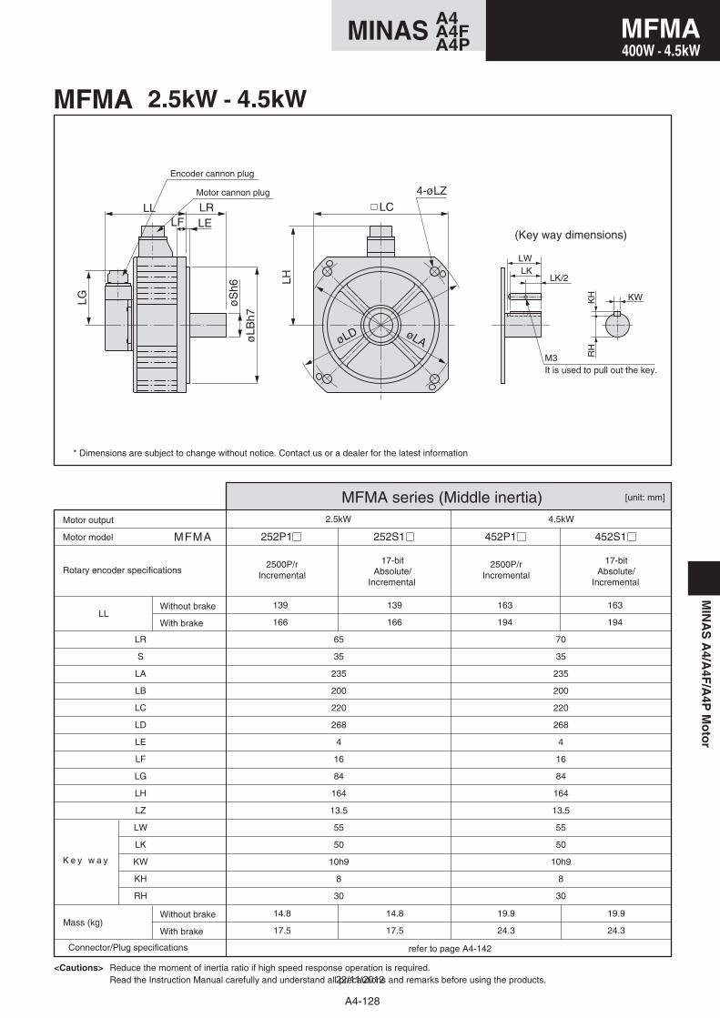
MIN
AS
A4/A
4F/A
4PM
oto
r
A4-128
A4MINAS A4FA4P
252P1 252S1 452P1 452S1
2.5kW 4.5kW
139
166
65
35
235
200
220
268
4
16
84
164
13.5
55
50
10h9
8
30
70
35
235
200
220
268
4
16
84
164
13.5
55
50
10h9
8
30
139
166
14.8
17.5
14.8
17.5
19.9
24.3
19.9
24.3
163
194
163
194
[unit: mm]
MFMA
LL
LR
S
LA
LB
LC
LD
LE
LF
LG
LH
LZ
LW
LK
KW
KH
RH
MFMA 2.5kW - 4.5kW
MFMA series (Middle inertia)
17-bit Absolute/
Incremental
17-bit Absolute/
Incremental
2500P/rIncremental
2500P/rIncremental
Motor model
Rotary encoder specifications
K e y w a y
Motor output
Mass (kg)
Connector/Plug specifications refer to page A4-142
Without brake
With brake
Without brake
With brake
<Cautions> Reduce the moment of inertia ratio if high speed response operation is required.Read the Instruction Manual carefully and understand all precautions and remarks before using the products.
* Dimensions are subject to change without notice. Contact us or a dealer for the latest information
Motor cannon plug
Encoder cannon plug
(Key way dimensions)
LL LRLF LE
øLB
h7
øS
h6
LH
LG
LC4-øLZ
øLD øLA
LWLK
KWKH
RH
LK/2
M3It is used to pull out the key.
MFMA400W - 4.5kW
22/11/2012
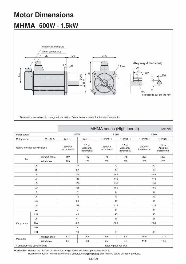
A4-129
[unit: mm]
052P1 052S1 102P1 102S1 152P1 152S1 MHMA
500W 1.0kW 1.5kW
LL150
175
70
22
145
110
130
165
6
12
84
118
9
45
41
8h9
7
18
70
22
145
110
130
165
6
12
84
118
9
45
41
8h9
7
18
70
22
145
110
130
165
6
12
84
118
9
45
41
8h9
7
18
150
175
5.3
6.9
5.3
6.9
8.9
9.5
8.9
9.5
10.0
11.6
10.0
11.6
175
200
175
200
200
225
200
225
LR
S
LA
LB
LC
LD
LE
LF
LG
LH
LZ
LW
LK
KW
KH
RH
MHMA 500W - 1.5kW
MHMA series (High inertia)
17-bit Absolute/
Incremental
17-bit Absolute/
Incremental
17-bit Absolute/
Incremental
2500P/rIncremental
2500P/rIncremental
2500P/rIncremental
Motor model
Rotary encoder specifications
K e y w a y
Motor output
Mass (kg)
Connector/Plug specifications refer to page A4-142
Without brake
With brake
Without brake
With brake
<Cautions> Reduce the moment of inertia ratio if high speed response operation is required.Read the Instruction Manual carefully and understand all precautions and remarks before using the products.
* Dimensions are subject to change without notice. Contact us or a dealer for the latest information
Motor cannon plug
Encoder cannon plug
(Key way dimensions)
LL LR
LF LE
øLB
h7
LH
LG
øS
h6
LC
4-øLZ
øLD øLA
LWLK
KW
KH
RH
LK/2
M3It is used to pull out the key.
Motor Dimensions
22/11/2012
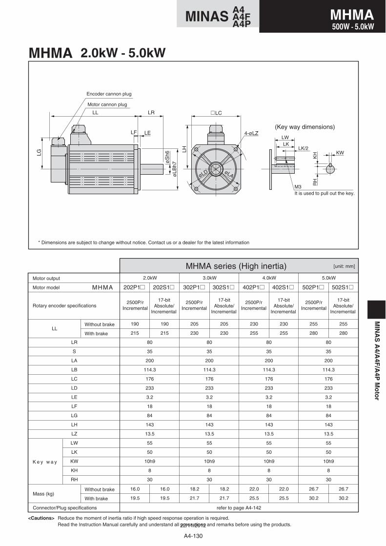
MIN
AS
A4/A
4F/A
4PM
oto
r
[unit: mm]
202P1 202S1 302P1 302S1 402P1 402S1 502P1 502S1 MHMA
2.0kW 3.0kW 4.0kW 5.0kW
LL190
215
190
215
205
230
205
230
230
255
230
255
255
280
255
280
80
35
200
114.3
176
233
3.2
18
84
143
13.5
55
50
10h9
8
30
80
35
200
114.3
176
233
3.2
18
84
143
13.5
55
50
10h9
8
30
80
35
200
114.3
176
233
3.2
18
84
143
13.5
55
50
10h9
8
30
80
35
200
114.3
176
233
3.2
18
84
143
13.5
55
50
10h9
8
30
16.0
19.5
16.0
19.5
18.2
21.7
18.2
21.7
22.0
25.5
22.0
25.5
26.7
30.2
26.7
30.2
LR
S
LA
LB
LC
LD
LE
LF
LG
LH
LZ
LW
LK
KW
KH
RH
MHMA 2.0kW - 5.0kW
MHMA series (High inertia)
17-bit Absolute/
Incremental
17-bit Absolute/
Incremental
17-bit Absolute/
Incremental
17-bit Absolute/
Incremental
2500P/rIncremental
2500P/rIncremental
2500P/rIncremental
2500P/rIncremental
Motor model
Rotary encoder specifications
K e y w a y
Motor output
Mass (kg)
Connector/Plug specifications refer to page A4-142
Without brake
With brake
Without brake
With brake
<Cautions> Reduce the moment of inertia ratio if high speed response operation is required.Read the Instruction Manual carefully and understand all precautions and remarks before using the products.
* Dimensions are subject to change without notice. Contact us or a dealer for the latest information
Motor cannon plug
Encoder cannon plug
(Key way dimensions)
LL LR
LF LE
øLB
h7
LH
LG
øS
h6
LC
4-øLZ
øLD øLA
LWLK
KW
KH
RH
LK/2
M3It is used to pull out the key.
A4-130
A4MINAS A4FA4P
MHMA500W - 5.0kW
22/11/2012
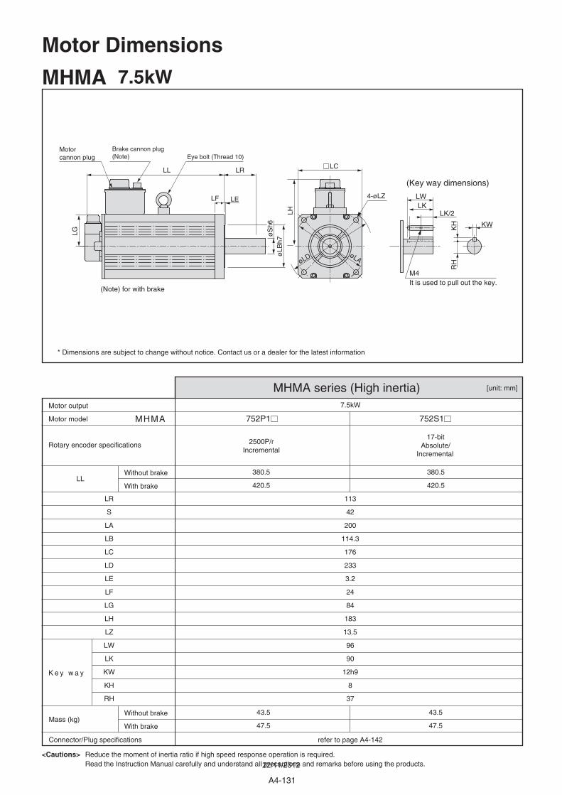
752P1 752S1 MHMA
7.5kW
LL380.5
420.5
113
42
200
114.3
176
233
3.2
24
84
183
13.5
96
90
12h9
8
37
380.5
420.5
43.5
47.5
43.5
47.5
LR
S
LA
LB
LC
LD
LE
LF
LG
LH
LZ
LW
LK
KW
KH
RH
MHMA 7.5kW
MHMA series (High inertia)
17-bit Absolute/
Incremental
2500P/rIncremental
Motor model
Rotary encoder specifications
K e y w a y
Motor output
Mass (kg)
Connector/Plug specifications refer to page A4-142
Without brake
With brake
Without brake
With brake
<Cautions> Reduce the moment of inertia ratio if high speed response operation is required.Read the Instruction Manual carefully and understand all precautions and remarks before using the products.
[unit: mm]
Motor Dimensions
Motor cannon plug
(Key way dimensions)
LH
LCLL LR
LF LE
øLB
h7
LG øS
h6
* Dimensions are subject to change without notice. Contact us or a dealer for the latest information
Brake cannon plug(Note) Eye bolt (Thread 10)
4-øLZ
øLAøLD
LWLK
KWKH
RH
LK/2
M4It is used to pull out the key.
(Note) for with brake
A4-131
22/11/2012
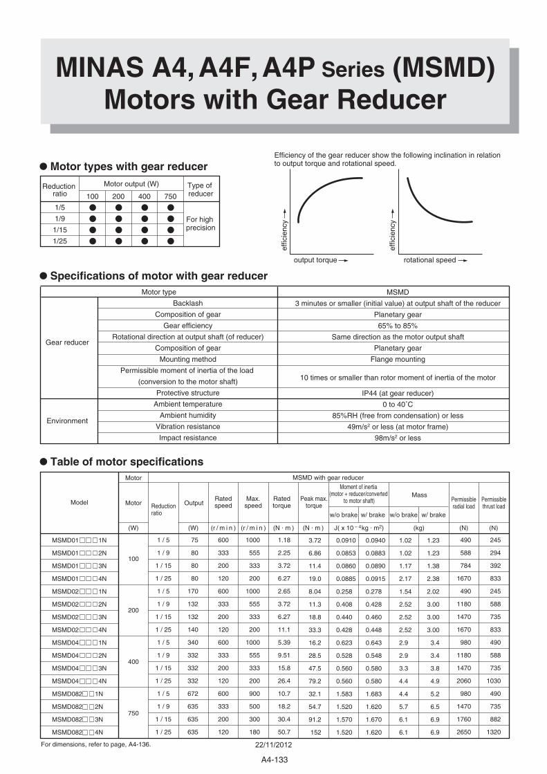
Backlash
Composition of gear
Gear efficiency
Rotational direction at output shaft (of reducer)
Composition of gear
Mounting method
Permissible moment of inertia of the load
(conversion to the motor shaft)
Protective structure
Ambient temperature
Ambient humidity
Vibration resistance
Impact resistance
Motor type
Gear reducer
Environment
MSMD
3 minutes or smaller (initial value) at output shaft of the reducer
Planetary gear
65% to 85%
Same direction as the motor output shaft
Planetary gear
Flange mounting
10 times or smaller than rotor moment of inertia of the motor
IP44 (at gear reducer)
0 to 40˚C
85%RH (free from condensation) or less
49m/s2 or less (at motor frame)
98m/s2 or less
• Specifications of motor with gear reducer
• Motor types with gear reducer
Reduction ratio
1/5
1/9
1/15
1/25
Type of reducer
For high precision
100 200 750400
Motor output (W)
MINAS A4, A4F, A4P Series (MSMD)Motors with Gear Reducer
Efficiency of the gear reducer show the following inclination in relation to output torque and rotational speed.
output torque rotational speed
effic
ienc
y
effic
ienc
y
Model Motor
Motor MSMD with gear reducer
Reduction ratio
OutputRatedspeed
Ratedtorque
Peak max.torque
Max.speed
Moment of inertia (motor + reducer/converted
to motor shaft)
w/o brake w/ brake w/o brake w/ brake
MassPermissibleradial load
Permissiblethrust load
(W) (W) (r / m i n ) (r / m i n ) (N . m ) (N . m ) J( x 10 – 4kg . m2) (kg) (N) (N)
MSMD01 1N
MSMD01 2N
MSMD01 3N
MSMD01 4N
MSMD02 1N
MSMD02 2N
MSMD02 3N
MSMD02 4N
MSMD04 1N
MSMD04 2N
MSMD04 3N
MSMD04 4N
MSMD082 1N
MSMD082 2N
MSMD082 3N
MSMD082 4N
100
200
400
750
75
80
80
80
170
132
132
140
340
332
332
332
672
635
635
635
600
333
200
120
600
333
200
120
600
333
200
120
600
333
200
120
1000
555
333
200
1000
555
333
200
1000
555
333
200
900
500
300
180
1 / 5
1 / 9
1 / 15
1 / 25
1 / 5
1 / 9
1 / 15
1 / 25
1 / 5
1 / 9
1 / 15
1 / 25
1 / 5
1 / 9
1 / 15
1 / 25
1.18
2.25
3.72
6.27
2.65
3.72
6.27
11.1
5.39
9.51
15.8
26.4
10.7
18.2
30.4
50.7
490
588
784
1670
490
1180
1470
1670
980
1180
1470
2060
980
1470
1760
2650
245
294
392
833
245
588
735
833
490
588
735
1030
490
735
882
1320
0.0910
0.0853
0.0860
0.0885
0.258
0.408
0.440
0.428
0.623
0.528
0.560
0.560
1.583
1.520
1.570
1.520
0.0940
0.0883
0.0890
0.0915
0.278
0.428
0.460
0.448
0.643
0.548
0.580
0.580
1.683
1.620
1.670
1.620
1.02
1.02
1.17
2.17
1.54
2.52
2.52
2.52
2.9
2.9
3.3
4.4
4.4
5.7
6.1
6.1
1.23
1.23
1.38
2.38
2.02
3.00
3.00
3.00
3.4
3.4
3.8
4.9
5.2
6.5
6.9
6.9
3.72
6.86
11.4
19.0
8.04
11.3
18.8
33.3
16.2
28.5
47.5
79.2
32.1
54.7
91.2
152
For dimensions, refer to page, A4-136.
• Table of motor specifications
A4-133
22/11/2012
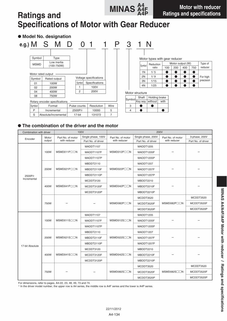
Ratings and Specifications of Motor with Gear Reducer
e.g.)
EncoderSingle phase, 100VPart No. of motor
with reducerPart No. of motor
with reducerPart No. of motor
with reducerPart No. of driverMotoroutput
2500P/r Incremental
17-bit Absolute
Combination with driver
MSMD011P N
MSMD021P N
MSMD041P N
–
MSMD011S N
MSMD021S N
MSMD041S N
–
–
–
–
MSMD082P N
–
–
–
MSMD082S N
MADDT1107
MADDT1107F
MADDT1107P
MBDDT2110
MBDDT2110F
MBDDT2110P
MCDDT3120
MCDDT3120F
MCDDT3120P
–
MADDT1107
MADDT1107F
MADDT1107P
MBDDT2110
MBDDT2110F
MBDDT2110P
MCDDT3120
MCDDT3120F
MCDDT3120P
–
MADDT1205
MADDT1205F
MADDT1205P
MADDT1207
MADDT1207F
MADDT1207P
MBDDT2210
MBDDT2210F
MBDDT2210P
MCDDT3520
MCDDT3520F
MCDDT3520P
MADDT1205
MADDT1205F
MADDT1205P
MADDT1207
MADDT1207F
MADDT1207P
MBDDT2210
MBDDT2210F
MBDDT2210P
MCDDT3520
MCDDT3520F
MCDDT3520P
MSMD012P N
MSMD022P N
MSMD042P N
MSMD082P N
MSMD012S N
MSMD022S N
MSMD042S N
MSMD082S N
100W
200W
400W
750W
100W
200W
400W
750W
For dimensions, refer to pages, A4-22, 23, 48, 49, 73 and 74.* In the driver model number, the upper row is A4 series, the middle row is A4F series and the lower is A4P series.
3-phase, 200V
100V 200V
Single phase, 200V
Part No. of driver
–
–
–
MCDDT3520
MCDDT3520F
MCDDT3520P
–
–
–
MCDDT3520
MCDDT3520F
MCDDT3520P
Part No. of driver
• Model No. designation
M S M D 0 1 1 P 3 1 N
Symbol
P
S
Symbol
MSMD
Type
Low inertia(100-750W)
Format
Incremental
Absolute/Incremental
Pulse counts
2500P/r
17-bit
Resolution
10000
131072
Wire
5
7
Symbol
01
02
04
08
Rated output
100W
200W
400W
750WSymbol
3
4
Shaftwithout withKey wayHolding brake
Symbol
1N
2N
3N
4N
Type of reducer
For high precision
100 200Reduction
ratio 400 750
Motor output (W)
Symbol
1
2
Specifications
100V
200V
1/ 5
1/ 9
1/15
1/25
Motor structure
Rotary encoder specifications
Motor rated outputVoltage specifications
Motor types with gear reducer
• The combination of the driver and the motor
MIN
AS
A4/A
4F/A
4PM
oto
rw
ithred
ucer
/R
ating
san
dsp
ecification
s
A4-134
A4MINAS A4FA4P
Motor with reducerRatings and specifications
22/11/2012
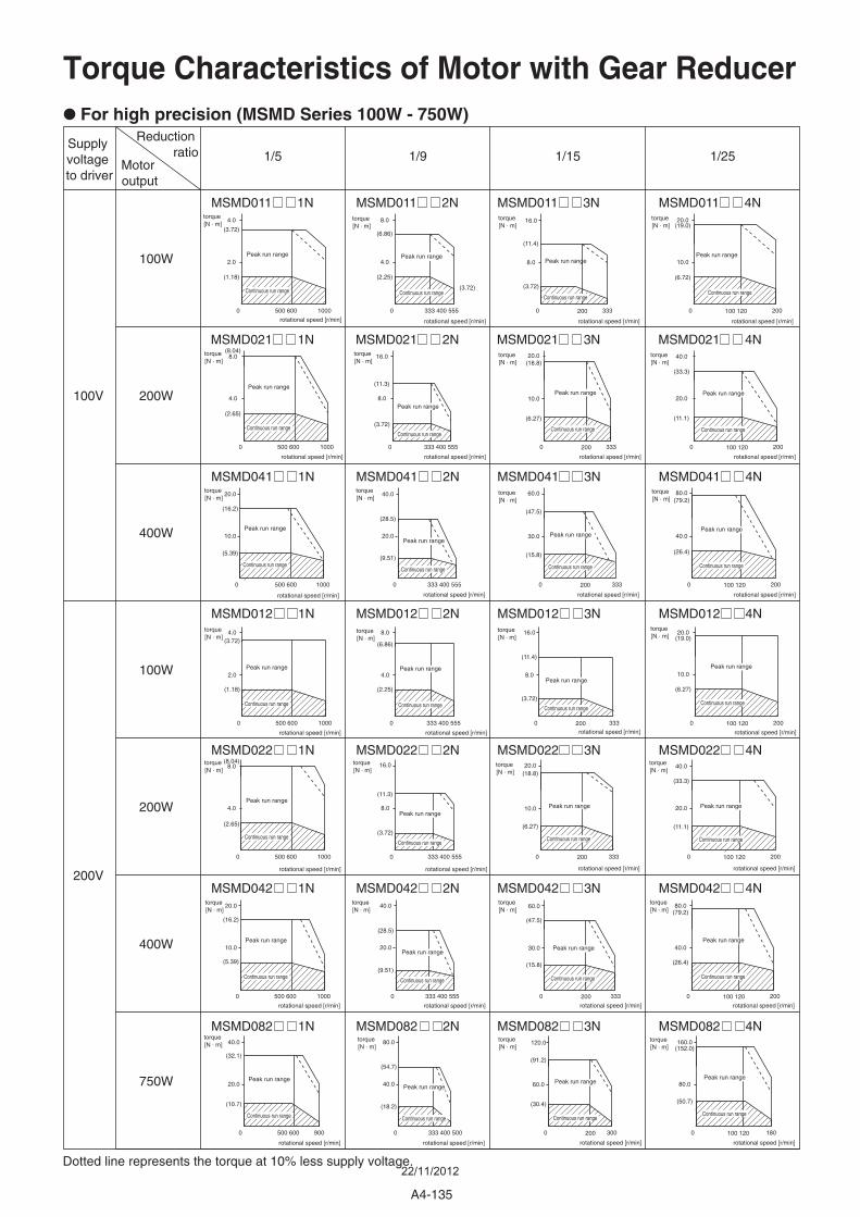
Torque Characteristics of Motor with Gear Reducer
• For high precision (MSMD Series 100W - 750W)
Supply voltage to driver
Reduction ratio
Motor output
Dotted line represents the torque at 10% less supply voltage.
1/5
MSMD011 1N MSMD011 2N MSMD011 3N MSMD011 4N
MSMD021 1N MSMD021 2N MSMD021 3N MSMD021 4N
MSMD041 1N MSMD041 2N MSMD041 3N MSMD041 4N
MSMD012 1N MSMD012 2N MSMD012 3N MSMD012 4N
MSMD022 1N MSMD022 2N MSMD022 3N MSMD022 4N
MSMD042 1N MSMD042 2N MSMD042 3N MSMD042 4N
MSMD082 1N MSMD082 2N MSMD082 3N MSMD082 4N
1/9 1/251/15
100W
100V
200V
100W
200W
200W
400W
750W
400W
0 500 600 1000 0 333 400 555
4.0
2.0
(3.72)
(1.18)
8.0
4.0
(6.86)
(2.25)
0 200 333
16.0
8.0
(11.4)
(3.72)
0 100 120 200
20.0(19.0)
10.0
(6.72)
0 500 600 1000 0 333 400 555
8.0(8.04)
(2.65)
4.0
16.0
8.0
(11.3)
(3.72)
0 200 333
20.0(18.8)
10.0
(6.27)
0 100 120 200
40.0
20.0
(33.3)
(11.1)
0 500 600 1000 0 333 400 555
20.0
10.0
(16.2)
(5.39)
40.0
20.0
(28.5)
(9.51)
0 200 333
60.0
30.0
(47.5)
(15.8)
0 100 120 200
80.0(79.2)
40.0
(26.4)
0 500 600 1000 0 333 400 555
20.0
10.0
(16.2)
(5.39)
40.0
20.0
(28.5)
(9.51)
0 200 333
60.0
30.0
(15.8)
(47.5)
0 100 120 200
80.0
40.0
(79.2)
(26.4)
0 500 600 900 0 333 400 500
40.0
(32.1)
(10.7)
20.0
80.0
(54.7)
(18.2)
40.0
0 200 300
120.0
60.0
(30.4)
(91.2)
0 100 120 180
160.0
80.0
(50.7)
(152.0)
0 500 600 1000 0 333 400 555
4.0
2.0
(3.72)
(1.18)
8.0
4.0
(6.86)
(2.25)
0 200 333
16.0
8.0
(11.4)
(3.72)
0 100 120 200
20.0(19.0)
10.0
(6.27)
0 500 600 1000 0 333 400 555
8.0(8.04)
(2.65)
4.0
16.0
8.0
(11.3)
(3.72)
(3.72)
0 200 333
20.0(18.8)
10.0
(6.27)
0 100 120 200
40.0
(33.3)
20.0
(11.1)
Continuous run range
Peak run range
rotational speed [r/min]
torque [N . m]
Continuous run range
Peak run range
rotational speed [r/min]
torque [N . m]
rotational speed [r/min]
torque [N . m]
Continuous run range
Peak run range
Peak run range
rotational speed [r/min]
torque [N . m]
Continuous run range
Peak run range
rotational speed [r/min]
torque [N . m]
Continuous run range
Peak run range
rotational speed [r/min]
torque [N . m]
Continuous run range
Peak run range
rotational speed [r/min]
torque [N . m]
Continuous run range
Peak run range
rotational speed [r/min]
torque [N . m]
Continuous run range
Peak run range
rotational speed [r/min]
torque [N . m]
Continuous run range
Peak run range
rotational speed [r/min]
torque [N . m]
Continuous run range
Peak run range
rotational speed [r/min]
torque [N . m]
Continuous run range
Peak run range
rotational speed [r/min]
torque [N . m]
Continuous run range
Peak run range
rotational speed [r/min]
torque [N . m]
Continuous run range
Peak run range
rotational speed [r/min]
torque [N . m]
Continuous run range
Peak run range
rotational speed [r/min]
torque [N . m]
Continuous run range
Peak run range
rotational speed [r/min]
torque [N . m]
Continuous run range
Peak run range
rotational speed [r/min]
torque [N . m]
Continuous run range
Peak run range
rotational speed [r/min]
torque [N . m]
Continuous run range
Peak run range
rotational speed [r/min]
torque [N . m]
Continuous run range
Peak run range
rotational speed [r/min]
torque [N . m]
Continuous run range
Peak run range
rotational speed [r/min]
torque [N . m]
Continuous run range
Peak run range
rotational speed [r/min]
torque [N . m]
Continuous run range
Peak run range
rotational speed [r/min]
torque [N . m]
Continuous run range
Peak run range
rotational speed [r/min]
torque [N . m]
Continuous run range
Peak run range
rotational speed [r/min]
torque [N . m]
Continuous run range
Peak run range
rotational speed [r/min]
torque [N . m]
Continuous run range
Peak run range
rotational speed [r/min]
torque [N . m]
Continuous run range
Peak run range
rotational speed [r/min]
torque [N . m]
Continuous run range
A4-135
22/11/2012
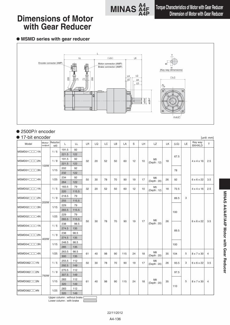
Dimensions of Motor with Gear Reducer
• MSMD series with gear reducer
• 2500P/r encoder
• 17-bit encoder
100W
200W
400W
750W
MSMD01 1N
MSMD01 2N
MSMD01 3N
MSMD01 4N
MSMD02 1N
MSMD02 2N
MSMD02 3N
MSMD02 4N
MSMD04 1N
MSMD04 2N
MSMD04 3N
MSMD04 4N
MSMD082 1N
MSMD082 2N
MSMD082 3N
MSMD082 4N
1 / 5
1 / 9
1/15
1/25
1 / 5
1 / 9
1/15
1/25
1 / 5
1 / 9
1/15
1/25
1 / 5
1 / 9
1/15
1/25
191.5
221.5
191.5
221.5
202
232
234
264
183.5
220
218.5
255
229
265.5
229
265.5
238
274.5
238
274.5
248.5
285
263.5
300
255.5
292.5
270.5
307.5
283
320
283
320
92
122
92
122
92
122
92
122
79
115.5
79
115.5
79
115.5
79
115.5
98.5
135
98.5
135
98.5
135
98.5
135
112
149
112
149
112
149
112
149
3
5
3
5
32
50
32
50
61
50
61
20
30
20
30
40
30
40
52
78
52
78
98
78
98
50
70
50
70
90
70
90
60
90
60
90
115
90
115
12
19
12
19
24
19
24
10
17
10
17
18
17
18
2.5
3.5
2.5
3.5
4
3.5
4
M5(Depth : 12)
M6(Depth : 20)
M5(Depth : 12)
M6(Depth : 20)
M8(Depth : 20)
M6(Depth : 20)
M8(Depth : 20)
4 x 4 x 16
6 x 6 x 22
4 x 4 x 16
6 x 6 x 22
8 x 7 x 30
6 x 6 x 22
8 x 7 x 30
18
26
18
26
35
26
35
67.5
78
92
72.5
89.5
100
89.5
100
104
93.5
97.5
110
Reduction rati0
L LL LR LQ LC LB LA S LH LZ LK (LG) LEKey wayBXHXLD
TMotor output
Model
Upper column : without brakeLower column : with brake
Encoder connecter (AMP) Motor connector (AMP)Brake connector (AMP)
)( LG
LK
LD
L
LL LR
LQ
LE
øS
h6
øLB
h7
LH
220
200
øLA
LC
4-øLZ
(7) (7)
H
B
T
(Key way dimensions)
[unit: mm]
MIN
AS
A4/A
4F/A
4PM
oto
rw
ithG
earR
edu
cer
A4-136
A4MINAS A4FA4P
Torque Characteristics of Motor with Gear ReducerDimension of Motor with Gear Reducer
22/11/2012
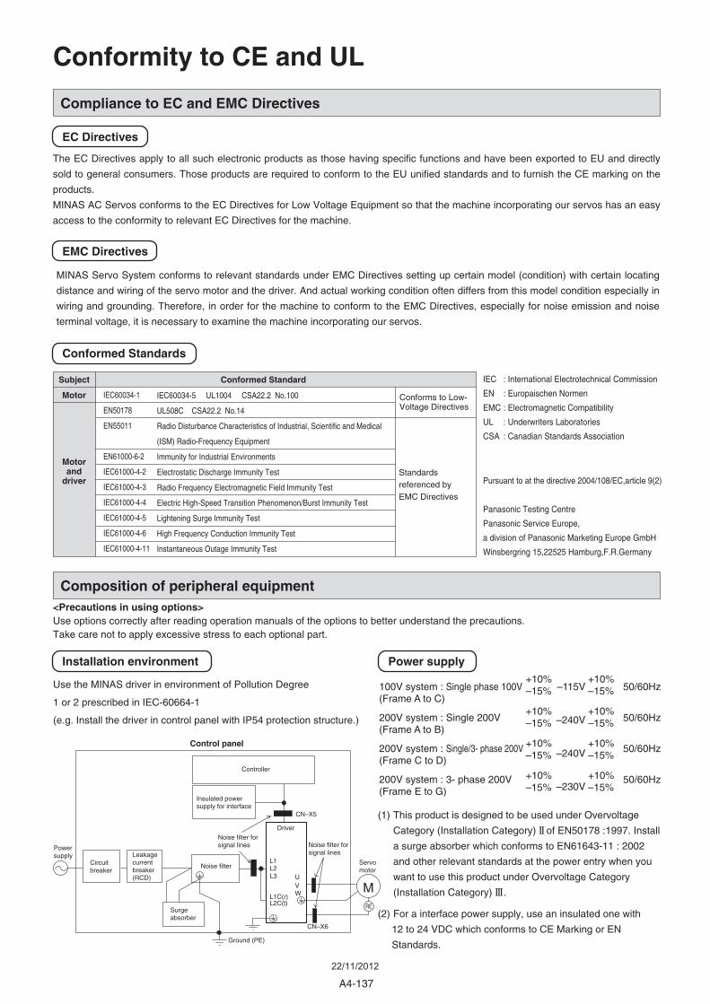
A4-137
Compliance to EC and EMC Directives
Composition of peripheral equipment
The EC Directives apply to all such electronic products as those having specific functions and have been exported to EU and directly
sold to general consumers. Those products are required to conform to the EU unified standards and to furnish the CE marking on the
products.
MINAS AC Servos conforms to the EC Directives for Low Voltage Equipment so that the machine incorporating our servos has an easy
access to the conformity to relevant EC Directives for the machine.
MINAS Servo System conforms to relevant standards under EMC Directives setting up certain model (condition) with certain locating
distance and wiring of the servo motor and the driver. And actual working condition often differs from this model condition especially in
wiring and grounding. Therefore, in order for the machine to conform to the EMC Directives, especially for noise emission and noise
terminal voltage, it is necessary to examine the machine incorporating our servos.
IEC : International Electrotechnical Commission
EN : Europaischen Normen
EMC : Electromagnetic Compatibility
UL : Underwriters Laboratories
CSA : Canadian Standards Association
Pursuant to at the directive 2004/108/EC,article 9(2)
Panasonic Testing Centre
Panasonic Service Europe,
a division of Panasonic Marketing Europe GmbH
Winsbergring 15,22525 Hamburg,F.R.Germany
Use the MINAS driver in environment of Pollution Degree
1 or 2 prescribed in IEC-60664-1
(e.g. Install the driver in control panel with IP54 protection structure.)
This product is intended to be used with a general industrial product, but not designed or manufactured to be used in a machine or system that may cause personal death when it is failed.
Conformed Standard
IEC60034-1
EN50178
EN55011
EN61000-6-2
IEC61000-4-2
IEC61000-4-3
IEC61000-4-4
IEC61000-4-5
IEC61000-4-6
IEC61000-4-11
IEC60034-5 UL1004 CSA22.2 No.100
UL508C CSA22.2 No.14
Radio Disturbance Characteristics of Industrial, Scientific and Medical
(ISM) Radio-Frequency Equipment
Immunity for Industrial Environments
Electrostatic Discharge Immunity Test
Radio Frequency Electromagnetic Field Immunity Test
Electric High-Speed Transition Phenomenon/Burst Immunity Test
Lightening Surge Immunity Test
High Frequency Conduction Immunity Test
Instantaneous Outage Immunity Test
Subject
Motor
Motorand
driver
Conforms to Low-Voltage Directives
Standards referenced by EMC Directives
Control panel
Controller
Insulated power supply for interface
Power supply
Circuit breaker
Leakage current breaker (RCD)
Surge absorber
Noise filter
Noise filter for signal lines
Ground (PE)
L1
U
CN–X5
CN–X6
MRE
VW
L2L3
L1C(r)L2C(t)
Noise filter for signal lines
Driver
Servo motor
EC Directives
EMC Directives
Conformed Standards
Installation environment Power supply
(1) This product is designed to be used under Overvoltage
Category (Installation Category) II of EN50178 :1997. Install
a surge absorber which conforms to EN61643-11 : 2002
and other relevant standards at the power entry when you
want to use this product under Overvoltage Category
(Installation Category) III .
(2) For a interface power supply, use an insulated one with
12 to 24 VDC which conforms to CE Marking or EN
Standards.
100V system : Single phase 100V(Frame A to C)
200V system : Single 200V(Frame A to B)
200V system : Single/3- phase 200V(Frame C to D)
200V system : 3- phase 200V(Frame E to G)
+10%–15%
+10%–15%
+10%–15%
+10%–15%
–115V
–240V
–240V
–230V
+10%–15%
+10%–15%
+10%–15%
+10%–15%
50/60Hz
50/60Hz
50/60Hz
50/60Hz
Conformity to CE and UL
<Precautions in using options>Use options correctly after reading operation manuals of the options to better understand the precautions.Take care not to apply excessive stress to each optional part.
22/11/2012
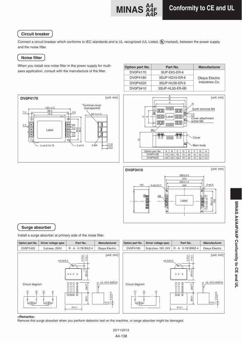
Connect a circuit breaker which conforms to IEC standards and is UL recognized (UL Listed, marked), between the power supply
and the noise filter.
When you install one noise filter in the power supply for multi-
axes application, consult with the manufacture of the filter.
Circuit breaker
Noise filter
Install a surge absorber at primary side of the noise filter.
Surge absorber
Option part No.
DV0P1450 R . A . V-781BXZ-4 Okaya Electric3-phase, 200V DV0P4190 R . A . V-781BWZ-4 Okaya ElectricSingle phase, 100V, 200V
Okaya Electric Industries Co.
Part No. Manufacturer
Option part No. Part No.Driver voltage spec Manufacturer
AOption part No. B C D E F G H115DV0P4180 105 95 70 43 10 52 5.5145 135 125 70 50 10 52 5.5DV0P4220
DV0P4170
DV0P4180
DV0P4220
SUP-EK5-ER-6
3SUP-HQ10-ER-6
3SUP-HU30-ER-6
DV0P3410 3SUP-HL50-ER-6B
DV0P4170
DV0P3410
Terminal cover (transparent) Earth terminal M4
Cover
Main body
Circuit diagram Circuit diagram
Cover attachment screw M3
Label
Label
Label
Option part No. Part No.Driver voltage spec Manufacturer
<Remarks>Remove this surge absorber when you perform dielectric test on the machine, or serge absorber might be damaged.
[unit: mm] [unit: mm]
[unit: mm]
[unit: mm][unit: mm]
MIN
AS
A4/A
4F/A
4PC
on
form
ityto
CE
and
UL
A4-138
A4MINAS A4FA4P
Conformity to CE and ULA4MINAS A4FA4P
22/11/2012
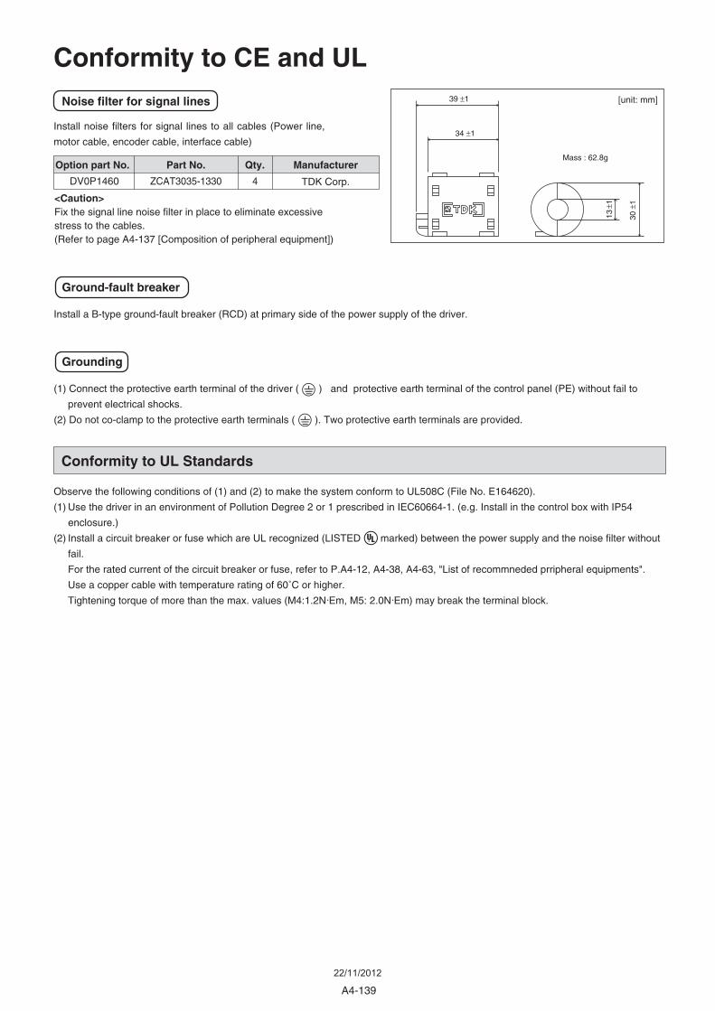
Conformity to UL Standards
Install noise filters for signal lines to all cables (Power line,
motor cable, encoder cable, interface cable)
(1) Connect the protective earth terminal of the driver ( ) and protective earth terminal of the control panel (PE) without fail to
prevent electrical shocks.
(2) Do not co-clamp to the protective earth terminals ( ). Two protective earth terminals are provided.
Observe the following conditions of (1) and (2) to make the system conform to UL508C (File No. E164620).
(1) Use the driver in an environment of Pollution Degree 2 or 1 prescribed in IEC60664-1. (e.g. Install in the control box with IP54
enclosure.)
(2) Install a circuit breaker or fuse which are UL recognized (LISTED marked) between the power supply and the noise filter without
fail.
For the rated current of the circuit breaker or fuse, refer to P.A4-12, A4-38, A4-63, "List of recommneded prripheral equipments".
Use a copper cable with temperature rating of 60˚C or higher.
Tightening torque of more than the max. values (M4:1.2N •Em, M5: 2.0N •Em) may break the terminal block.
Noise filter for signal lines
Grounding
39 ±1
34 ±1
30 ±
1
13 ±
1
Mass : 62.8g
Install a B-type ground-fault breaker (RCD) at primary side of the power supply of the driver.
Ground-fault breaker
Option part No.
TDK Corp.
Part No. Manufacturer
DV0P1460 ZCAT3035-1330
Qty.
4
Conformity to CE and UL
<Caution>Fix the signal line noise filter in place to eliminate excessive stress to the cables.(Refer to page A4-137 [Composition of peripheral equipment])
[unit: mm]
A4-139
22/11/2012
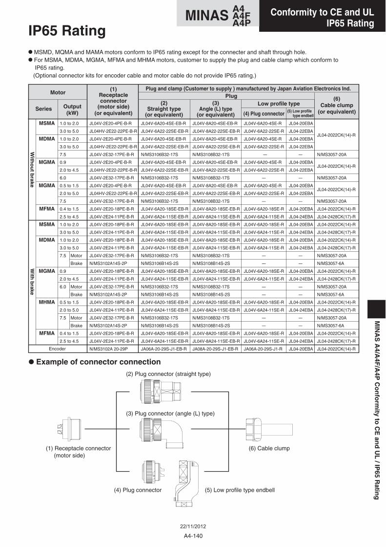
• MSMD, MQMA and MAMA motors conform to IP65 rating except for the connecter and shaft through hole.
• For MSMA, MDMA, MGMA, MFMA and MHMA motors, customer to supply the plug and cable clamp which conform to IP65 rating. (Optional connector kits for encoder cable and motor cable do not provide IP65 rating.)
(1)Receptacleconnector
(motor side)(or equivalent)
MotorPlug
Low profile type
Plug and clamp (Customer to supply ) manufactured by Japan Aviation Electronics Ind.
(2)Straight type
(or equivalent)
(3)Angle (L) type
(or equivalent) (4) Plug connectorSeries Output
(kW)
(6)Cable clump
(or equivalent)
With
ou
t brake
With
brake
JL04V-2E20-4PE-B-R
JL04HV-2E22-22PE-B-R
JL04V-2E20-4PE-B-R
JL04HV-2E22-22PE-B-R
JL04V-2E32-17PE-B-R
JL04V-2E20-4PE-B-R
JL04HV-2E22-22PE-B-R
JL04V-2E32-17PE-B-R
JL04V-2E20-4PE-B-R
JL04HV-2E22-22PE-B-R
JL04V-2E32-17PE-B-R
JL04V-2E20-18PE-B-R
JL04V-2E24-11PE-B-R
JL04V-2E20-18PE-B-R
JL04V-2E24-11PE-B-R
JL04V-2E20-18PE-B-R
JL04V-2E24-11PE-B-R
JL04V-2E32-17PE-B-R
N/MS3102A14S-2P
JL04V-2E20-18PE-B-R
JL04V-2E24-11PE-B-R
JL04V-2E32-17PE-B-R
N/MS3102A14S-2P
JL04V-2E20-18PE-B-R
JL04V-2E24-11PE-B-R
JL04V-2E32-17PE-B-R
N/MS3102A14S-2P
JL04V-2E20-18PE-B-R
JL04V-2E24-11PE-B-R
N/MS3102A 20-29P
MSMA
MDMA
MGMA
MGMA
MFMA
MSMA
MDMA
MGMA
MHMA
MFMA
1.0 to 2.0
3.0 to 5.0
1.0 to 2.0
3.0 to 5.0
7.5
0.9
2.0 to 4.5
6.0
0.5 to 1.5
2.0 to 5.0
7.5
0.4 to 1.5
2.5 to 4.5
1.0 to 2.0
3.0 to 5.0
1.0 to 2.0
3.0 to 5.0
7.5 Motor
Brake
0.9
2.0 to 4.5
6.0 Motor
Brake
0.5 to 1.5
2.0 to 5.0
7.5 Motor
Brake
0.4 to 1.5
2.5 to 4.5
JL04V-6A20-4SE-EB-R
JL04V-6A22-22SE-EB-R
JL04V-6A20-4SE-EB-R
JL04V-6A22-22SE-EB-R
N/MS3106B32-17S
JL04V-6A20-4SE-EB-R
JL04V-6A22-22SE-EB-R
N/MS3106B32-17S
JL04V-6A20-4SE-EB-R
JL04V-6A22-22SE-EB-R
N/MS3106B32-17S
JL04V-6A20-18SE-EB-R
JL04V-6A24-11SE-EB-R
JL04V-6A20-18SE-EB-R
JL04V-6A24-11SE-EB-R
JL04V-6A20-18SE-EB-R
JL04V-6A24-11SE-EB-R
N/MS3106B32-17S
N/MS3106B14S-2S
JL04V-6A20-18SE-EB-R
JL04V-6A24-11SE-EB-R
N/MS3106B32-17S
N/MS3106B14S-2S
JL04V-6A20-18SE-EB-R
JL04V-6A24-11SE-EB-R
N/MS3106B32-17S
N/MS3106B14S-2S
JL04V-6A20-18SE-EB-R
JL04V-6A24-11SE-EB-R
JA06A-20-29S-J1-EB-R
JL04V-8A20-4SE-EB-R
JL04V-8A22-22SE-EB-R
JL04V-8A20-4SE-EB-R
JL04V-8A22-22SE-EB-R
N/MS3108B32-17S
JL04V-8A20-4SE-EB-R
JL04V-8A22-22SE-EB-R
N/MS3108B32-17S
JL04V-8A20-4SE-EB-R
JL04V-8A22-22SE-EB-R
N/MS3108B32-17S
JL04V-8A20-18SE-EB-R
JL04V-8A24-11SE-EB-R
JL04V-8A20-18SE-EB-R
JL04V-8A24-11SE-EB-R
JL04V-8A20-18SE-EB-R
JL04V-8A24-11SE-EB-R
N/MS3108B32-17S
N/MS3108B14S-2S
JL04V-8A20-18SE-EB-R
JL04V-8A24-11SE-EB-R
N/MS3108B32-17S
N/MS3108B14S-2S
JL04V-8A20-18SE-EB-R
JL04V-8A24-11SE-EB-R
N/MS3108B32-17S
N/MS3108B14S-2S
JL04V-8A20-18SE-EB-R
JL04V-8A24-11SE-EB-R
JA08A-20-29S-J1-EB-R
JL04V-6A20-4SE-R
JL04V-6A22-22SE-R
JL04V-6A20-4SE-R
JL04V-6A22-22SE-R
–
JL04V-6A20-4SE-R
JL04V-6A22-22SE-R
–
JL04V-6A20-4SE-R
JL04V-6A22-22SE-R
–
JL04V-6A20-18SE-R
JL04V-6A24-11SE-R
JL04V-6A20-18SE-R
JL04V-6A24-11SE-R
JL04V-6A20-18SE-R
JL04V-6A24-11SE-R
–
–
JL04V-6A20-18SE-R
JL04V-6A24-11SE-R
–
–
JL04V-6A20-18SE-R
JL04V-6A24-11SE-R
–
–
JL04V-6A20-18SE-R
JL04V-6A24-11SE-R
JA06A-20-29S-J1-R
JL04-20EBA
JL04-22EBA
JL04-20EBA
JL04-22EBA
–
JL04-20EBA
JL04-22EBA
–
JL04-20EBA
JL04-22EBA
–
JL04-20EBA
JL04-24EBA
JL04-20EBA
JL04-24EBA
JL04-20EBA
JL04-24EBA
–
–
JL04-20EBA
JL04-24EBA
–
–
JL04-20EBA
JL04-24EBA
–
–
JL04-20EBA
JL04-24EBA
JL04-20EBA
JL04-2022CK(14)-R
N/MS3057-20A
JL04-2022CK(14)-R
N/MS3057-20A
JL04-2022CK(14)-R
N/MS3057-20A
JL04-2022CK(14)-R
JL04-2428CK(17)-R
JL04-2022CK(14)-R
JL04-2428CK(17)-R
JL04-2022CK(14)-R
JL04-2428CK(17)-R
N/MS3057-20A
N/MS3057-6A
JL04-2022CK(14)-R
JL04-2428CK(17)-R
N/MS3057-20A
N/MS3057-6A
JL04-2022CK(14)-R
JL04-2428CK(17)-R
N/MS3057-20A
N/MS3057-6A
JL04-2022CK(14)-R
JL04-2428CK(17)-R
JL04-2022CK(14)-REncoder
• Example of connector connection(2) Plug connector (straight type)
(3) Plug connector (angle (L) type)
(4) Plug connector (5) Low profile type endbell
(6) Cable clump(1) Receptacle connector (motor side)
(5) Low profile type endbell
IP65 Rating
MIN
AS
A4/A
4F/A
4PC
on
form
ityto
CE
and
UL
/IP65
Ratin
g
A4-140
A4MINAS A4FA4P
Conformity to CE and ULIP65 Rating
A4MINAS A4FA4P
22/11/2012
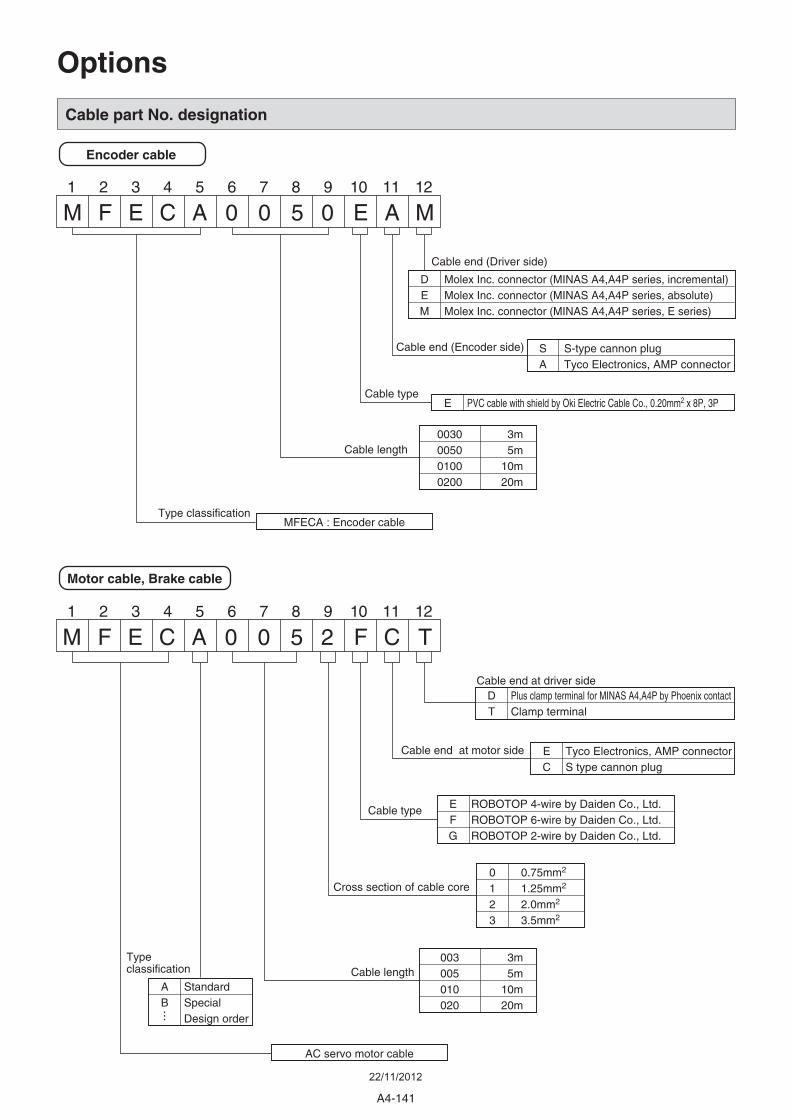
A4-141
Cable part No. designation
Encoder cable
Molex Inc. connector (MINAS A4,A4P series, incremental)Molex Inc. connector (MINAS A4,A4P series, absolute)Molex Inc. connector (MINAS A4,A4P series, E series)
DEM
S-type cannon plugTyco Electronics, AMP connector
SA
3m5m
10m20m
0030005001000200
PVC cable with shield by Oki Electric Cable Co., 0.20mm2 x 8P, 3PE
MFECA : Encoder cable
Cable end (Driver side)
Cable end (Encoder side)
Cable type
Cable length
Type classification
Motor cable, Brake cable
Plus clamp terminal for MINAS A4,A4P by Phoenix contactClamp terminal
DT
Tyco Electronics, AMP connectorS type cannon plug
EC
3m5m
10m20m
003005010020
ROBOTOP 4-wire by Daiden Co., Ltd.ROBOTOP 6-wire by Daiden Co., Ltd.ROBOTOP 2-wire by Daiden Co., Ltd.
EFG
AC servo motor cable
Cable end at driver side
Cable end at motor side
Cable type
Cable length
0.75mm2
1.25mm2
2.0mm2
3.5mm2
0123
Cross section of cable core
StandardSpecialDesign order
AB
Type classification
M F E C A 0 0 5 0 E A M1 2 3 4 5 6 7 8 9 10 11 12
M F E C A 0 0 5 2 F C T1 2 3 4 5 6 7 8 9 10 11 12
Options
22/11/2012
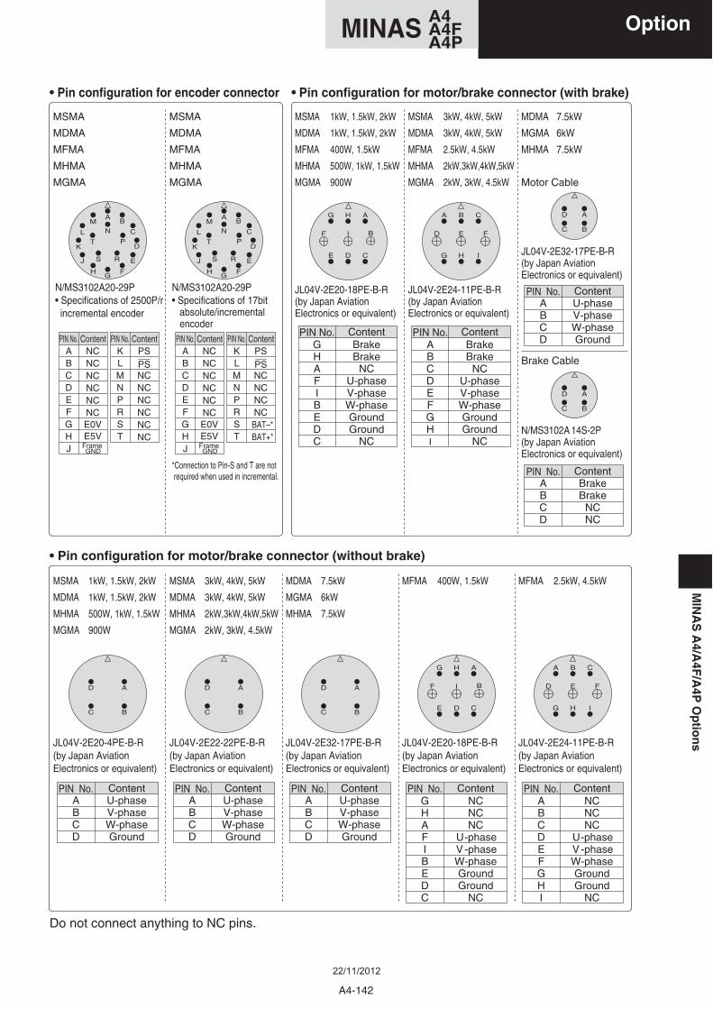
• Specifications of 2500P/r incremental encoder
• Specifications of 17bit absolute/incremental encoder
*Connection to Pin-S and T are not required when used in incremental.
PIN No. ContentNCNCNCNCNCNCE0VE5VFrame GND
PIN No. Content
NCNCNCNCNCNC
PSPS
PSPS
PIN No. ContentNCNCNCNCNCNCE0VE5VFrame GND
PIN No.ABCDEFGHJ
KLMNPRST
ABCDEFGHJ
KLMNPRST
Content
NCNCNCNC
BAT–*BAT+*
N/MS3102A20-29P N/MS3102A20-29P
A
N
B
C
PD
ER
FG
H
SJ
M
T
L
K
A
N
B
C
PD
ER
FG
H
SJ
M
T
L
K
PIN No.ABCD
ContentU-phaseV-phaseW-phaseGround
JL04V-2E20-4PE-B-R(by Japan Aviation Electronics or equivalent)
D A
BC
APIN No.
BCD
ContentU-phaseV-phaseW-phaseGround
JL04V-2E22-22PE-B-R(by Japan Aviation Electronics or equivalent)
D A
BC
D A
BC
MSMA
MDMA
MFMA
MHMA
MGMA
• Pin configuration for encoder connector
JL04V-2E32-17PE-B-R(by Japan Aviation Electronics or equivalent)
Do not connect anything to NC pins.
MSMA
MDMA
MFMA
MHMA
MGMA
MSMA 1kW, 1.5kW, 2kW
MDMA 1kW, 1.5kW, 2kW
MHMA 500W, 1kW, 1.5kW
MGMA 900W
MSMA 3kW, 4kW, 5kW
MDMA 3kW, 4kW, 5kW
MHMA 2kW,3kW,4kW,5kW
MGMA 2kW, 3kW, 4.5kW
MDMA 7.5kW
MGMA 6kW
MHMA 7.5kW
• Pin configuration for motor/brake connector (without brake)
GPIN No.
HAFIBEDC
ContentNCNCNC
U-phase V -phaseW-phaseGroundGround
NC
DE C
H
I
G A
F B
APIN No.
BCDEFGHI
ContentNCNCNC
U-phase V -phaseW-phaseGroundGround
NC
JL04V-2E20-18PE-B-R(by Japan Aviation Electronics or equivalent)
JL04V-2E24-11PE-B-R(by Japan Aviation Electronics or equivalent)
HG I
ED F
BA C
MFMA 400W, 1.5kW MFMA 2.5kW, 4.5kW
APIN No.
BCD
ContentU-phaseV-phaseW-phaseGround
PIN No.GHAFIBEDC
ContentBrakeBrake
NCU-phaseV-phaseW-phaseGroundGround
NC
DE C
H
I
G A
F B
APIN No.
BCDEFGHI
ContentBrakeBrake
NCU-phaseV-phaseW-phaseGroundGround
NC
JL04V-2E20-18PE-B-R(by Japan Aviation Electronics or equivalent)
JL04V-2E24-11PE-B-R(by Japan Aviation Electronics or equivalent)
HG I
ED F
BA C
MSMA 1kW, 1.5kW, 2kW
MDMA 1kW, 1.5kW, 2kW
MFMA 400W, 1.5kW
MHMA 500W, 1kW, 1.5kW
MGMA 900W
MSMA 3kW, 4kW, 5kW
MDMA 3kW, 4kW, 5kW
MFMA 2.5kW, 4.5kW
MHMA 2kW,3kW,4kW,5kW
MGMA 2kW, 3kW, 4.5kW
MDMA 7.5kW
MGMA 6kW
MHMA 7.5kW
• Pin configuration for motor/brake connector (with brake)
Motor Cable
N/MS3102A 14S-2P(by Japan Aviation Electronics or equivalent)
JL04V-2E32-17PE-B-R(by Japan Aviation Electronics or equivalent)
Brake Cable
APIN No.
BCD
ContentBrakeBrake
NCNC
APIN No.
BCD
ContentU-phaseV-phaseW-phaseGround
D A
BC
D A
BC
A4-142
A4MINAS A4FA4P
MIN
AS
A4/A
4F/A
4PO
ptio
ns
Option
22/11/2012
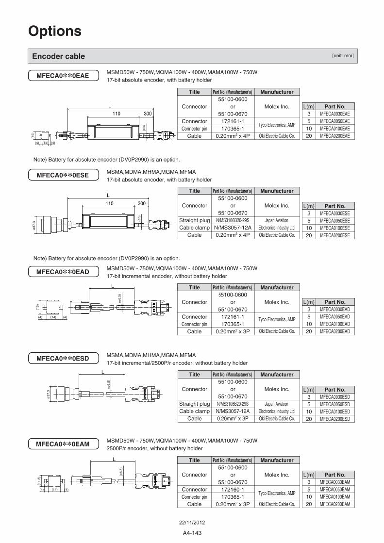
110 300
L
300110
L
Encoder cable
MFECA0**0EAE
MFECA0**0ESE
MSMD50W - 750W,MQMA100W - 400W,MAMA100W - 750W17-bit absolute encoder, with battery holder
MSMA,MDMA,MHMA,MGMA,MFMA17-bit absolute encoder, with battery holder
MFECA0**0EAD
MFECA0**0ESD
MFECA0**0EAM
MSMD50W - 750W,MQMA100W - 400W,MAMA100W - 750W17-bit incremental encoder, without battery holder
MSMA,MDMA,MHMA,MGMA,MFMA17-bit incremental/2500P/r encoder, without battery holder
MSMD50W - 750W,MQMA100W - 400W,MAMA100W - 750W2500P/r encoder, without battery holder
L
(ø6.
5)
L
(ø6.
5)
L
(ø6.
5)
L(m)35
1020
Part No.MFECA0030EADMFECA0050EADMFECA0100EADMFECA0200EAD
L(m)35
1020
Part No.MFECA0030ESDMFECA0050ESDMFECA0100ESDMFECA0200ESD
Title
Connector
Straight plugCable clamp
Cable
Manufacturer
Molex Inc.
Japan Aviation Electronics Industry Ltd.Oki Electric Cable Co.
Part No. (Manufacturer's) 55100-0600
or55100-0670
N/MS3106B20-29SN/MS3057-12A0.20mm2 x 3P
L(m)35
1020
Part No.MFECA0030ESEMFECA0050ESEMFECA0100ESEMFECA0200ESE
Title
Connector
Straight plugCable clamp
Cable
Manufacturer
Molex Inc.
Japan Aviation Electronics Industry Ltd.Oki Electric Cable Co.
Part No. (Manufacturer's) 55100-0600
or55100-0670
N/MS3106B20-29SN/MS3057-12A0.20mm2 x 4P
Title
Connector
ConnectorConnector pin
Cable
Manufacturer
Molex Inc.
Tyco Electronics, AMP
Oki Electric Cable Co.
Part No. (Manufacturer's) 55100-0600
or55100-0670
172161-1170365-1
0.20mm2 x 3P
L(m)35
1020
Part No.MFECA0030EAMMFECA0050EAMMFECA0100EAMMFECA0200EAM
Title
Connector
ConnectorConnector pin
Cable
Manufacturer
Molex Inc.
Tyco Electronics, AMP
Oki Electric Cable Co.
Part No. (Manufacturer's) 55100-0600
or55100-0670
172160-1170365-1
0.20mm2 x 3P
L(m)35
1020
Part No.MFECA0030EAEMFECA0050EAEMFECA0100EAEMFECA0200EAE
Title
Connector
ConnectorConnector pin
Cable
Manufacturer
Molex Inc.
Tyco Electronics, AMP
Oki Electric Cable Co.
Part No. (Manufacturer's) 55100-0600
or55100-0670
172161-1170365-1
0.20mm2 x 4P(ø
8)
(ø8)
(14)
(16)
(4) (4)
(14)
(16)
(4) (4)
(14)
(11.
8)
(4) (4)
ø37
.3
ø37
.3
Note) Battery for absolute encoder (DV0P2990) is an option.
Note) Battery for absolute encoder (DV0P2990) is an option.
Options
[unit: mm]
A4-143
22/11/2012
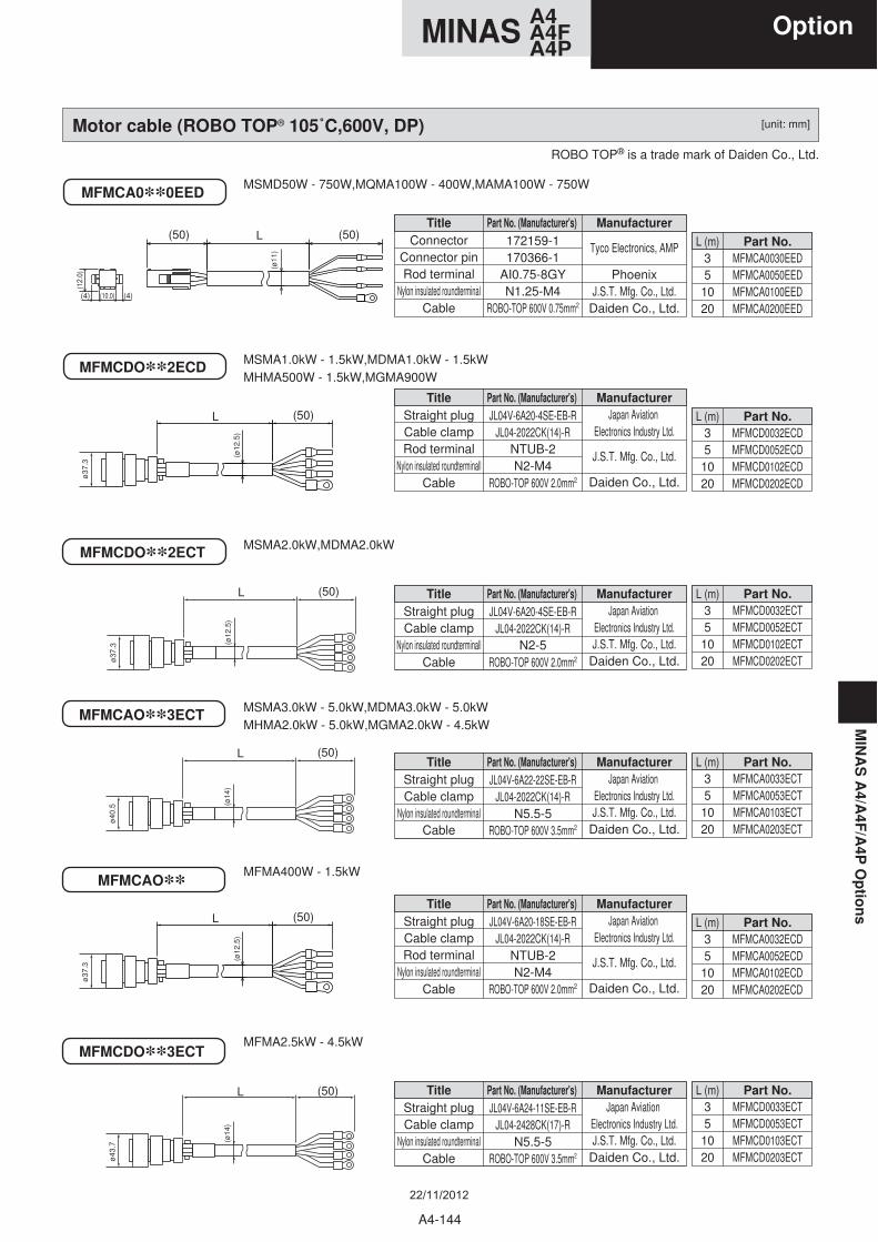
MFMCAO**3ECT
MFMCDO**3ECT
(ø14
)
(50)L
ø43
.7
(ø14
)
(50)L
ø40
.5
MFMCAO**
Motor cable (ROBO TOP® 105˚C,600V, DP)
MFMCA0**0EEDMSMD50W - 750W,MQMA100W - 400W,MAMA100W - 750W
MSMA1.0kW - 1.5kW,MDMA1.0kW - 1.5kWMHMA500W - 1.5kW,MGMA900W
MSMA3.0kW - 5.0kW,MDMA3.0kW - 5.0kWMHMA2.0kW - 5.0kW,MGMA2.0kW - 4.5kW
MFMA400W - 1.5kW
MFMA2.5kW - 4.5kW
MSMA2.0kW,MDMA2.0kW
MFMCDO**2ECD
MFMCDO**2ECT
(50)L
ø37
.3 (ø12
.5)
(50)L
(ø12
.5)
(50)L
(ø12
.5)
L (m)351020
Part No.MFMCA0030EEDMFMCA0050EEDMFMCA0100EEDMFMCA0200EED
TitleConnector
Connector pinRod terminal
Nylon insulated roundterminalCable
Manufacturer
Tyco Electronics, AMP
PhoenixJ.S.T. Mfg. Co., Ltd.
Daiden Co., Ltd.
Part No. (Manufacturer's) 172159-1170366-1
AI0.75-8GYN1.25-M4
ROBO-TOP 600V 0.75mm2
L (m)351020
Part No.MFMCD0032ECDMFMCD0052ECDMFMCD0102ECDMFMCD0202ECD
TitleStraight plugCable clampRod terminal
Nylon insulated roundterminallCable
ManufacturerJapan Aviation
Electronics Industry Ltd.
J.S.T. Mfg. Co., Ltd.
Daiden Co., Ltd.
Part No. (Manufacturer's) JL04V-6A20-4SE-EB-R
JL04-2022CK(14)-RNTUB-2N2-M4
ROBO-TOP 600V 2.0mm2
L (m)351020
Part No.MFMCA0032ECDMFMCA0052ECDMFMCA0102ECDMFMCA0202ECD
TitleStraight plugCable clampRod terminal
Nylon insulated roundterminalCable
ManufacturerJapan Aviation
Electronics Industry Ltd.
J.S.T. Mfg. Co., Ltd.
Daiden Co., Ltd.
Part No. (Manufacturer's) JL04V-6A20-18SE-EB-R
JL04-2022CK(14)-RNTUB-2N2-M4
ROBO-TOP 600V 2.0mm2
L (m)351020
Part No.MFMCD0032ECTMFMCD0052ECTMFMCD0102ECTMFMCD0202ECT
TitleStraight plugCable clamp
Nylon insulated roundterminallCable
ManufacturerJapan Aviation
Electronics Industry Ltd.J.S.T. Mfg. Co., Ltd.
Daiden Co., Ltd.
Part No. (Manufacturer's) JL04V-6A20-4SE-EB-R
JL04-2022CK(14)-RN2-5
ROBO-TOP 600V 2.0mm2
L (m)351020
Part No.MFMCA0033ECTMFMCA0053ECTMFMCA0103ECTMFMCA0203ECT
TitleStraight plugCable clamp
Nylon insulated roundterminalCable
ManufacturerJapan Aviation
Electronics Industry Ltd.J.S.T. Mfg. Co., Ltd.
Daiden Co., Ltd.
Part No. (Manufacturer's) JL04V-6A22-22SE-EB-R
JL04-2022CK(14)-RN5.5-5
ROBO-TOP 600V 3.5mm2
L (m)351020
Part No.MFMCD0033ECTMFMCD0053ECTMFMCD0103ECTMFMCD0203ECT
TitleStraight plugCable clamp
Nylon insulated roundterminalCable
ManufacturerJapan Aviation
Electronics Industry Ltd.J.S.T. Mfg. Co., Ltd.
Daiden Co., Ltd.
Part No. (Manufacturer's) JL04V-6A24-11SE-EB-R
JL04-2428CK(17)-RN5.5-5
ROBO-TOP 600V 3.5mm2
ø37
.3
(50) (50)L
(ø11
)
(10.0)
(12.
0)
(4) (4)
ø37
.3
ROBO TOP® is a trade mark of Daiden Co., Ltd.
[unit: mm]
MIN
AS
A4/A
4F/A
4P O
ptio
ns
A4-144
A4MINAS A4FA4P
Option
22/11/2012
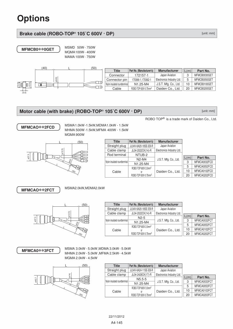
MFMCAO**2FCD
Motor cable (with brake) (ROBO-TOP® 105˚C 600V . DP)
L (50)
L
(50)
(ø12
.5)
MFMCAO**2FCT
L (50)
L
(50)
ø37
.3
ø37
.3
(ø12
.5)
(ø9.
8)
(ø9.
8)
Brake cable (ROBO-TOP® 105˚C 600V . DP)
MFMCB0**0GET
(ø9.
8)
(40) (50)L
(5.6)
(12.
0)
(10.
0)
MSMD 50W - 750WMQMA100W - 400WMAMA 100W - 750W
MSMA1.0kW-1.5kW,MDMA1.0kW - 1.5kWMHMA 500W-1.5kW,MFMA 400W - 1.5kWMGMA 900W
MSMA2.0kW,MDMA2.0kW
MSMA 3.0kW - 5.0kW,MDMA 3.0kW- 5.0kWMHMA 2.0kW - 5.0kW ,MFMA 2.5kW- 4.5kWMGMA 2.0kW - 4.5kW
MFMCA0**3FCT
L (50)
L
(50)
ø43
.7 (ø14
)
(ø9.
8)
L(m)351020
Part No.MFMCA0032FCDMFMCA0052FCDMFMCA0102FCDMFMCA0202FCD
TitleStraight plugCable clampRod terminal
Nylon insulated roundterminal
Cable
ManufacturerJapan Aviation
Electronics Industry Ltd.
J.S.T. Mfg. Co., Ltd.
Daiden Co., Ltd.
Part No. (Manufacturer's) JL04V-6A20-18SE-EB-R
JL04-2022CK(14)-RNTUB-2N2-M4
N1.25-M4ROBO-TOP 600V 2.0mm2
orROBO-TOP 600V 0.75mm2
L(m)351020
Part No.MFMCA0032FCTMFMCA0052FCTMFMCA0102FCTMFMCA0202FCT
TitleStraight plugCable clamp
Nylon insulated roundterminal
Cable
ManufacturerJapan Aviation
Electronics Industry Ltd.
J.S.T. Mfg. Co., Ltd.
Daiden Co., Ltd.
Part No. (Manufacturer's) JL04V-6A20-18SE-EB-R
JL04-2022CK(14)-RN2-5
N1.25-M4ROBO-TOP 600V 2.0mm2
orROBO-TOP 600V 0.75mm2
L(m)351020
Part No.MFMCA0033FCTMFMCA0053FCTMFMCA0103FCTMFMCA0203FCT
TitleStraight plugCable clamp
Nylon insulated roundterminal
Cable
ManufacturerJapan Aviation
Electronics Industry Ltd.
J.S.T. Mfg. Co., Ltd.
Daiden Co., Ltd.
Part No. (Manufacturer's) JL04V-6A24-11SE-EB-R
JL04-2428CK(17)-RN5.5-5
N1.25-M4ROBO-TOP 600V 3.5mm2
orROBO-TOP 600V 0.75mm2
L(m)351020
Part No.MFMCB0030GETMFMCB0050GETMFMCB0100GETMFMCB0200GET
TitleConnector
Connector pinNylon insulated roundterminal
Cable
ManufacturerJapan Aviation
Electronics Industry Ltd.J.S.T. Mfg. Co., Ltd.Daiden Co., Ltd.
Part No. (Manufacturer's) 172157-1
170366-1,170362-1N1.25-M4
ROBO-TOP 600V 0.75mm2
ROBO TOP® is a trade mark of Daiden Co., Ltd.
Options
[unit: mm]
[unit: mm]
A4-145
22/11/2012
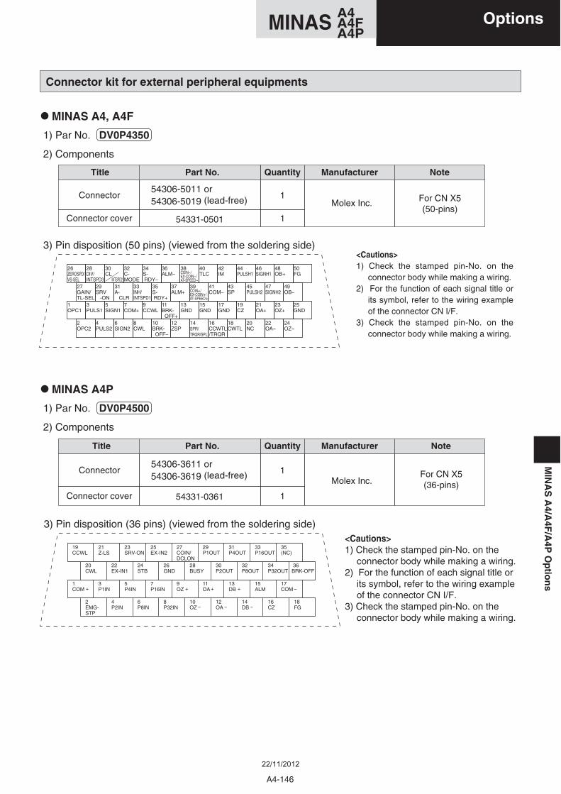
Connector kit for external peripheral equipments
• MINAS A4, A4F
• MINAS A4P
3) Pin disposition (36 pins) (viewed from the soldering side)<Cautions>1) Check the stamped pin-No. on the
connector body while making a wiring. 2) For the function of each signal title or
its symbol, refer to the wiring example of the connector CN I/F.
3) Check the stamped pin-No. on the connector body while making a wiring.
19CCWL
21Z-LS
23SRV-ON
25EX-IN2
27COIN/DCLON
29P1OUT
31P4OUT
33P16OUT
35(NC)
20CWL
22EX-IN1
24STB
26GND
28BUSY
30P2OUT
32P8OUT
34P32OUT
36BRK-OFF
1COM
3P1IN
5P4IN
7P16IN
9OZ
11OA
13DB
15ALM
17COM
2EMG-STP
4P2IN
6P8IN
8P32IN
10OZ
12OA
14DB
16CZ
18FG
Connector
Connector cover
Title
54331-0361
QuantityPart No. Manufacturer Note
1
1
54306-3611 or 54306-3619 (lead-free) For CN X5
(36-pins)Molex Inc.
1) Par No. DV0P4500
2) Components
3) Pin disposition (50 pins) (viewed from the soldering side)
Connector
Connector cover
Title
54331-0501
QuantityPart No. Manufacturer Note
26ZEROSPD/VS-SEL
28DIV/INTSPD3
30CL INTSPD2
32C-MODE
34S- RDY
36ALM
38COIN-/EX-COIN-/AT-SPEED-
40TLC
42IM
44PULSH1
46SIGNH1
48OB
27GAIN/TL-SEL
29SRV -ON
31A- CLR
33INH/INTSPD1
35S- RDY
37ALM
39COIN+/EX-COIN+/AT-SPEED+
41COM
43SP
45PULSH2
47SIGNH2
49OB
1OPC1
3PULS1
5SIGN1
7COM
9CCWL
11BRK- OFF
13GND
15GND
17GND
19CZ
21OA
23OZ
2OPC2
4PULS2
6SIGN2
8CWL
10BRK- OFF
12ZSP
14SPR/TRQR/SPL /TRQR
16CCWTL
18CWTL
20NC
22OA
24OZ
50FG
25GND
<Cautions>1) Check the stamped pin-No. on the
connector body while making a wiring. 2) For the function of each signal title or
its symbol, refer to the wiring example of the connector CN I/F.
3) Check the stamped pin-No. on the connector body while making a wiring.
1
1
54306-5011 or 54306-5019 (lead-free) For CN X5
(50-pins)Molex Inc.
1) Par No. DV0P4350
2) Components
MIN
AS
A4/A
4F/A
4PO
ptio
ns
A4-146
A4MINAS A4FA4P
Options
22/11/2012
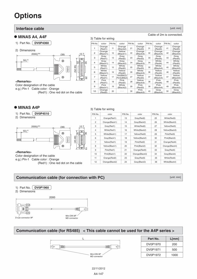
1) Part No.2) Dimensions
<Remarks>Color designation of the cablee.g.) Pin-1 Cable color : Orange (Red1) : One red dot on the cable
3) Table for wiring
PIN No.
1
2
3
4
5
6
7
8
9
10
11
12
PIN No.
13
14
15
16
17
18
19
20
21
22
23
24
PIN No.
25
26
27
28
29
30
31
32
33
34
35
36
color
Orange(Red1)
Orange(Black1)
Gray(Red1)
White(Red1)
White(Black1)
Gray(Black1)
Yellow(Red1)
Yellow(Black1)
Pink(Red1)
Pink(Black1)
Orange(Red2)
Orange(Black2)
color
Gray(Red2)
Gray(Black2)
White(Red2)
White(Black2)
Yellow(Red2)
Yellow(Black2)
Pink(Red2)
Pink(Black2)
Orange(Red3)
Orange(Black3)
Gray(Red3)
Gray(Black3)
color
White(Red3)
White(Black3)
Yellow(Red3)
Yellow(Black3)
Pink(Red3)
Pink(Black3)
Orange(Red4)
Orange(Black4)
Gray(Red4)
Gray(Black4)
White(Red4)
White(Black4)
Communication cable (for connection with PC)
2000
D-sub connector 9PMini-DIN 8PMD connector
L[mm]
DV0P1970
DV0P1971
DV0P1972
Part No.
Communication cable (for RS485) < This cable cannot be used for the A4P series >
200
500
1000Mini-DIN 8PMD connector
L
Interface cable
1) Part No. DV0P4360
2) Dimensions
Cable of 2m is connected.
125 50
26
(52.
35)
2000+2000
50+100
(39) 12.7
<Remarks>Color designation of the cablee.g.) Pin-1 Cable color : Orange (Red1) : One red dot on the cable
molex
3) Table for wiring
PIN No.
1
2
3
4
5
6
7
8
9
10
PIN No.
11
12
13
14
15
16
17
18
19
20
PIN No.
21
22
23
24
25
26
27
28
29
30
PIN No.
31
32
33
34
35
36
37
38
39
40
PIN No.
41
42
43
44
45
46
47
48
49
50
color
Orange(Red1)Orange(Black1)
Gray(Red1)Gray
(Black1)White(Red1)White
(Black1)Yellow(Red1)Pink
(Red1)Pink
(Black1)Orange(Red2)
color
Orange(Black2)Yellow
(Black1)Gray
(Red2)Gray
(Black2)White(Red2)Yellow(Red2)
Yel(Blk2)/Pink(Blk2)
Pink(Red2)White
(Black2)
color
Orange(Red3)Orange(Black3)
Gray(Red3)Gray
(Black3)White(Red3)White
(Black3)Yellow(Red3)Yellow
(Black3)Pink
(Red3)Pink
(Black3)
color
Orange(Red4)Orange(Black4)
Gray(Red4)White(Red4)White
(Black4)Yellow(Red4)Yellow
(Black4)Pink
(Red4)Pink
(Black4)Gray
(Black4)
color
Orange(Red5)Orange(Black5)
Gray(Red5)White(Red5)White
(Black5)Yellow(Red5)Yellow
(Black5)Pink
(Red5)Pink
(Black5)Gray
(Black5)
118 36
19
(43.
46)
20000
50+100
+200 (39) 12.7m
olex
1) Part No.2) Dimensions
DV0P1960
DV0P4510
• MINAS A4P
• MINAS A4, A4F
Options
[unit: mm]
[unit: mm]
A4-147
22/11/2012
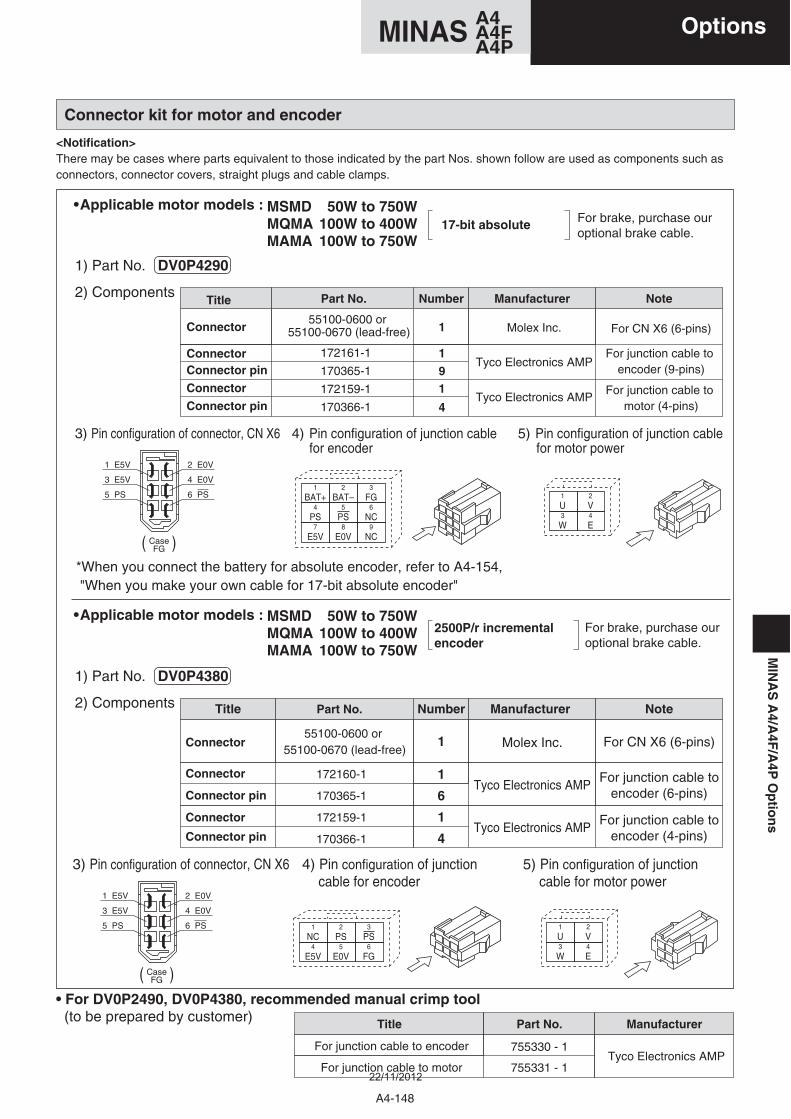
1) Part No. DV0P4290
2) Components
( )
2500P/r incremental encoder
Title
1
NumberPart No.
55100-0600 or 55100-0670 (lead-free)
172160-1
170365-1
172159-1
170366-1
Manufacturer
For CN X6 (6-pins)
1
6For junction cable to
encoder (6-pins)
1
Note
4For junction cable to
encoder (4-pins)
For brake, purchase our optional brake cable.
3) Pin configuration of connector, CN X6 4) Pin configuration of junction cable for encoder
5) Pin configuration of junction cable for motor power
6 PS5 PS
2 E0V1 E5V
4 E0V 3 E5V
CaseFG
1
NC2
PS3
PS4
E5V5
E0V6
FG
1
U2
V3
W4
E
3) Pin configuration of connector, CN X6
*When you connect the battery for absolute encoder, refer to A4-154, "When you make your own cable for 17-bit absolute encoder"
4) Pin configuration of junction cable for encoder
5) Pin configuration of junction cable for motor power
Title NumberPart No.
55100-0600 or 55100-0670 (lead-free)
172161-1
170365-1
172159-1
170366-1
Manufacturer Note
1) Part No. DV0P4380
2) Components
For brake, purchase our optional brake cable.
6 PS5 PS
2 E0V1 E5V
4 E0V 3 E5V
CaseFG
1
BAT+2
BAT–3
FG4
PS5
PS6
NC7
E5V8
E0V9
NC
1
U2
V3
W4
E
17-bit absolute
• Applicable motor models :
• Applicable motor models :
Connector
ConnectorConnector pin
Connector
Connector pin
Molex Inc.
Tyco Electronics AMP
Tyco Electronics AMP
For CN X6 (6-pins)
For junction cable to encoder (9-pins)
For junction cable to motor (4-pins)
1
1
19
4
( )
Connector
Connector
Connector pin
Connector
Connector pin
Tyco Electronics AMP
Tyco Electronics AMP
Molex Inc.
MSMD 50W to 750WMQMA 100W to 400WMAMA 100W to 750W
MSMD 50W to 750WMQMA 100W to 400WMAMA 100W to 750W
Connector kit for motor and encoder
<Notification>There may be cases where parts equivalent to those indicated by the part Nos. shown follow are used as components such as connectors, connector covers, straight plugs and cable clamps.
Title Part No. Manufacturer
• For DV0P2490, DV0P4380, recommended manual crimp tool (to be prepared by customer)
Tyco Electronics AMPFor junction cable to encoder
For junction cable to motor
755330 - 1
755331 - 1
MIN
AS
A4/A
4F/A
4PO
ptio
ns
A4-148
A4MINAS A4FA4P
Options
22/11/2012
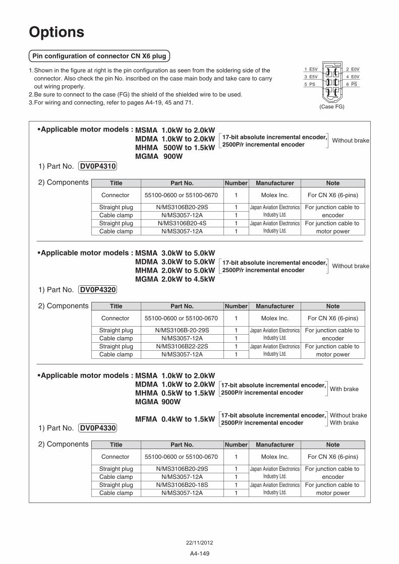
Without brake
Note
For CN X6 (6-pins)
For junction cable to encoder
For junction cable to motor power
Number
1
1111
Title
Connector
Straight plugCable clampStraight plugCable clamp
Part No.
55100-0600 or 55100-0670
N/MS3106B20-29SN/MS3057-12A
N/MS3106B20-18SN/MS3057-12A
Note
For CN X6 (6-pins)
For junction cable to encoder
For junction cable to motor power
Number
1
1111
Title
Connector
Straight plugCable clampStraight plugCable clamp
Part No.
55100-0600 or 55100-0670
N/MS3106B-20-29SN/MS3057-12A
N/MS3106B22-22SN/MS3057-12A
Note
For CN X6 (6-pins)
For junction cable to encoder
For junction cable to motor power
Manufacturer
Molex Inc.
Japan Aviation ElectronicsIndustry Ltd.
Japan Aviation ElectronicsIndustry Ltd.
Manufacturer
Molex Inc.
Japan Aviation ElectronicsIndustry Ltd.
Japan Aviation ElectronicsIndustry Ltd.
Manufacturer
Molex Inc.
Japan Aviation ElectronicsIndustry Ltd.
Japan Aviation ElectronicsIndustry Ltd.
Number
1
1111
Title
Connector
Straight plugCable clampStraight plugCable clamp
Part No.
55100-0600 or 55100-0670
N/MS3106B20-29SN/MS3057-12A
N/MS3106B20-4SN/MS3057-12A
17-bit absolute incremental encoder,2500P/r incremental encoder
Without brake17-bit absolute incremental encoder,2500P/r incremental encoder
With brake17-bit absolute incremental encoder,2500P/r incremental encoder
Without brakeWith brake
17-bit absolute incremental encoder,2500P/r incremental encoder
1) Part No. DV0P4310
2) Components
• Applicable motor models : MSMA 1.0kW to 2.0kWMDMA 1.0kW to 2.0kWMHMA 500W to 1.5kWMGMA 900W
1) Part No. DV0P4320
2) Components
• Applicable motor models : MSMA 3.0kW to 5.0kWMDMA 3.0kW to 5.0kWMHMA 2.0kW to 5.0kWMGMA 2.0kW to 4.5kW
1) Part No. DV0P4330
2) Components
• Applicable motor models : MSMA 1.0kW to 2.0kWMDMA 1.0kW to 2.0kWMHMA 0.5kW to 1.5kWMGMA 900W
MFMA 0.4kW to 1.5kW
Options
6 PS5 PS
2 E0V1 E5V
4 E0V3 E5V
(Case FG)
1.Shown in the figure at right is the pin configuration as seen from the soldering side of the connector. Also check the pin No. inscribed on the case main body and take care to carry out wiring properly.
2.Be sure to connect to the case (FG) the shield of the shielded wire to be used.3.For wiring and connecting, refer to pages A4-19, 45 and 71.
Pin configuration of connector CN X6 plug
A4-149
22/11/2012
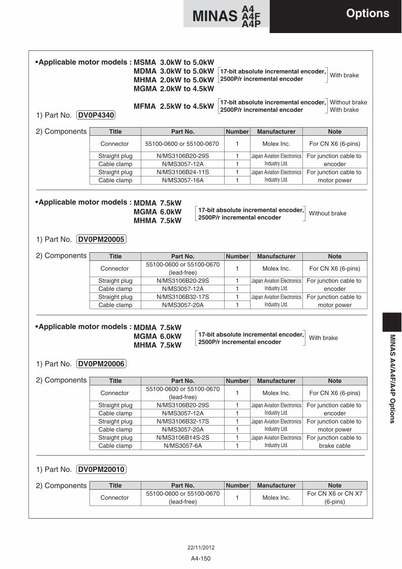
Without brake
Note
For CN X6 (6-pins)
For junction cable to encoder
For junction cable to motor power
Manufacturer
Molex Inc.
Japan Aviation ElectronicsIndustry Ltd.
Japan Aviation ElectronicsIndustry Ltd.
Number
1
1111
Title
Connector
Straight plugCable clampStraight plugCable clamp
Part No.55100-0600 or 55100-0670
(lead-free)N/MS3106B20-29S
N/MS3057-12AN/MS3106B32-17S
N/MS3057-20A
17-bit absolute incremental encoder,2500P/r incremental encoder
1) Part No. DV0PM20005
2) Components
• Applicable motor models : MDMA 7.5kWMGMA 6.0kWMHMA 7.5kW
With brake17-bit absolute incremental encoder,2500P/r incremental encoder
1) Part No. DV0PM20006
2) Components
• Applicable motor models : MDMA 7.5kWMGMA 6.0kWMHMA 7.5kW
1) Part No. DV0PM20010
2) Components
Note
For CN X6 (6-pins)
For junction cable to encoder
For junction cable to motor power
Number
1
1111
Title
Connector
Straight plugCable clampStraight plugCable clamp
Part No.
55100-0600 or 55100-0670
N/MS3106B20-29SN/MS3057-12A
N/MS3106B24-11SN/MS3057-16A
Manufacturer
Molex Inc.
Japan Aviation ElectronicsIndustry Ltd.
Japan Aviation ElectronicsIndustry Ltd.
With brake17-bit absolute incremental encoder,2500P/r incremental encoder
Without brakeWith brake
17-bit absolute incremental encoder,2500P/r incremental encoder
1) Part No. DV0P4340
2) Components
• Applicable motor models : MSMA 3.0kW to 5.0kWMDMA 3.0kW to 5.0kWMHMA 2.0kW to 5.0kWMGMA 2.0kW to 4.5kW
MFMA 2.5kW to 4.5kW
Note
For CN X6 (6-pins)
For junction cable to encoder
For junction cable to motor power
For junction cable to brake cable
Manufacturer
Molex Inc.
Japan Aviation ElectronicsIndustry Ltd.
Japan Aviation ElectronicsIndustry Ltd.
Japan Aviation ElectronicsIndustry Ltd.
Number
1
111111
Title
Connector
Straight plugCable clampStraight plugCable clampStraight plugCable clamp
Part No.55100-0600 or 55100-0670
(lead-free)N/MS3106B20-29S
N/MS3057-12AN/MS3106B32-17S
N/MS3057-20AN/MS3106B14S-2S
N/MS3057-6A
NoteFor CN X6 or CN X7
(6-pins)
Manufacturer
Molex Inc.
Number
1
Title
Connector
Part No.55100-0600 or 55100-0670
(lead-free)
A4-150
A4MINAS A4FA4P
MIN
AS
A4/A
4F/A
4PO
ptio
ns
Options
22/11/2012
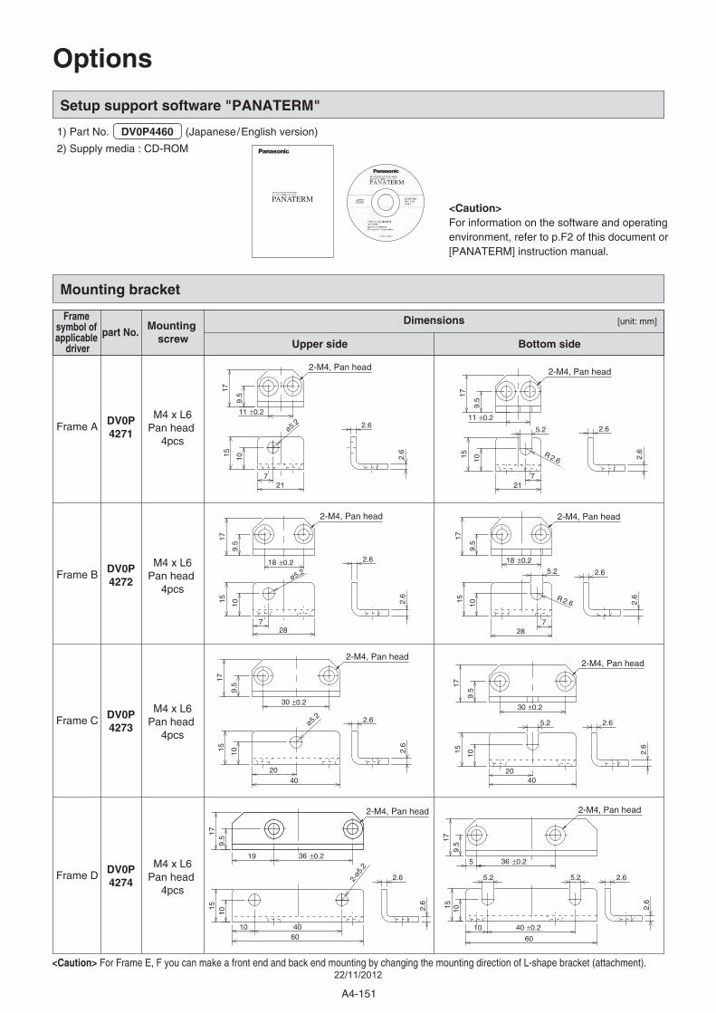
Setup support software "PANATERM"
1) Part No. DV0P4460 (Japanese/English version)
2) Supply media : CD-ROM
<Caution> For Frame E, F you can make a front end and back end mounting by changing the mounting direction of L-shape bracket (attachment).
Mounting bracket
Frame symbol of applicable
driver
part No.Mounting
screw
Dimensions
Upper side Bottom side
Frame AM4 x L6
Pan head 4pcs
M4 x L6Pan head
4pcs
M4 x L6Pan head
4pcs
M4 x L6Pan head
4pcs
Frame B
Frame C
Frame D DV0P4274
DV0P4273
DV0P4272
DV0P4271
Options
2-M4, Pan head
5.2
11 ±0.2
9.5
21
15 2.6
17
10
2.6
7
2.6R
2-M4, Pan head
2.6
10
17
2.6
7
15
21
9.5
11 ±0.2
ø5.2
2-M4, Pan head
2.6
10
17
2.6
15
28
9.5
18 ±0.2
5.2
7
2.6R
2-M4, Pan head
18 ±0.2
28
15 2.6
10
2.6
17
9.5
7
ø5.2
2-M4, Pan head
5.2 2.6
10
17
2.6
15
40
9.5
30 ±0.2
20
2-M4, Pan head
30 ±0.2
9.5
40
15 2.6
17
10
2.6
20
ø5.2
2-M4, Pan head
5.2
5
179.
5
36 ±0.2
40 ±0.210
5.2 2.6
10 2.6
15
60
2-M4, Pan head
4010
179.
5
36 ±0.2
60
15 2.6
10
2.6
19
5.2
2-ø
PANATERM <Caution>For information on the software and operating environment, refer to p.F2 of this document or [PANATERM] instruction manual.
[unit: mm]
A4-151
22/11/2012
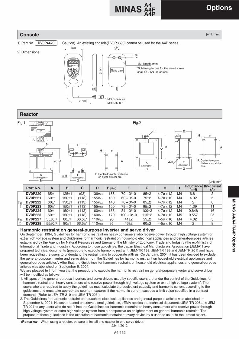
Reactor
C
B
A(Mounting pitch)
D
6-I
R S T
NP
X Y Z
B
C D
2-I
G
4-H F(Mounting pitch)
E
G
4-H
E
Fig.1 Fig.2
Console
1) Part No. DV0P4420
2) Dimensions
Caution) An existing console(DV0P3690) cannot be used for the A4P series.
A(Mounting pitch)
F(Mounting pitch)
Harmonic restraint on general-purpose inverter and servo driverOn September, 1994, Guidelines for harmonic restraint on heavy consumers who receive power through high voltage system or extra high voltage system and Guidelines for harmonic restraint on household electrical appliances and general-purpose articles established by the Agency for Natural Resources and Energy of the Ministry of Economy, Trade and Industry (the ex-Ministry of International Trade and Industry). According to those guidelines, the Japan Electrical Manufacturers Association (JEMA) have prepared technical documents (procedure to execute harmonic restraint: JEM-TR 198, JEM-TR 199 and JEM-TR 201) and have been requesting the users to understand the restraint and to cooperate with us. On January, 2004, it has been decided to exclude the general-purpose inverter and servo driver from the Guidelines for harmonic restraint on household electrical appliances and general-purpose articles”. After that, the Guidelines for harmonic restraint on household electrical appliances and general-purpose articles was abolished on September 6, 2004.We are pleased to inform you that the procedure to execute the harmonic restraint on general-purpose inverter and servo driver will be modified as follows.1. All types of the general-purpose inverters and servo drivers used by specific users are under the control of the Guidelines for
harmonic restraint on heavy consumers who receive power through high voltage system or extra high voltage system”. The users who are required to apply the guidelines must calculate the equivalent capacity and harmonic current according to the guidelines and must take appropriate countermeasures if the harmonic current exceeds a limit value specified in a contract demand. (Refer to JEM-TR 210 and JEM-TR 225.)
2. The Guidelines for harmonic restraint on household electrical appliances and general-purpose articles was abolished on September 6, 2004. However, based on conventional guidelines, JEMA applies the technical documents JEM-TR 226 and JEM-TR 227 to any users who do not fit into the Guidelines for harmonic restraint on heavy consumers who receive power through high voltage system or extra high voltage system from a perspective on enlightenment on general harmonic restraint. The purpose of these guidelines is the execution of harmonic restraint at every device by a user as usual to the utmost extent.
<Remarks> When using a reactor, be sure to install one reactor to one servo driver.
Name plate
(62)
(15)
(24)
M3 length 5mm
(15)
(114
)(1500)
MD connectorMini DIN-8P
Tightening torque for the insert screwshall be 0.5N . m or less
A
AH
H
F
F: Center-to-center distanceon outer circular arc
F: Center-to-centerdistance on slottedhole
F
DV0P220DV0P221DV0P222DV0P223DV0P224DV0P225DV0P227DV0P228
65±160±160±160±160±160±1
55±0.755±0.7
125±1150±1150±1150±1150±1150±180±180±1
(93)(113)(113)(113)(113)(113)
66.5±166.5±1
136Max
155Max
155Max
155Max
160Max
160Max
110Max
110Max
1551301401501551709095
70 + 3/–060 + 3/–070 + 3/–079 + 3/–084 + 3/–0100 + 3/–0
41±246±2
85±275±285±295±2
100±2115±255±260±2
4-7ø X 124-7ø X 124-7ø X 124-7ø X 124-7ø X 124-7ø X 124-5ø X 104-5ø X 10
M4M4M4M4M4M5M4M4
6.814.02
21.39
0.8480.5574.02
2
35811162558
Fig.1
Fig.2
Part No. A B C D E (Max) F G H I Inductance(mH)
Rated current(A)
[unit: mm]
[unit: mm]
MIN
AS
A4/A
4F/A
4PO
ptio
ns
A4-152
A4MINAS A4FA4P
Options
22/11/2012
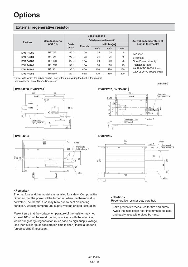
External regenerative resistor
Take preventive measures for fire and burns.Avoid the installation near inflammable objects,and easily accessible place by hand.
<Caution>Regenerative resistor gets very hot.
Options
Manufacturer : Iwaki Musen Kenkyusho
Manufacturer's part No.
DV0P4282
DV0P4283
DV0P4284
Part No.
Specifications
Activation temperature of built-in thermostat
DV0P4280
DV0P4281
DV0P4285
*Power with which the driver can be used without activating the built-in thermostat.
Resistance
with fan[W]
Reted power (reference)*
Free air1m/s 2m/s 3m/s
RF70M
RF70M
RF180B
RF180B
RF240
RH450F
25
25
50
50
100
130
10W
10W
17W
17W
40W
52W
50 Ω
100 Ω
25 Ω
50 Ω
30 Ω
20 Ω
35
35
60
60
120
160
45
45
75
75
150
200
140 ±5˚CB-contactOpen/Close capacity(resistance load)4A 125VAC 10000 times2.5A 250VAC 10000 times
<Remarks>Thermal fuse and thermostat are installed for safety. Compose the circuit so that the power will be turned off when the thermostat is activated.The thermal fuse may blow due to heat dissipating condition, working temperature, supply voltage or load fluctuation.
Make it sure that the surface temperature of the resistor may not exceed 100˚C at the worst running conditions with the machine, which brings large regeneration (such case as high supply voltage, load inertia is large or deceleration time is short) Install a fan for a forced cooling if necessary.
2-ø4.5
65
60
30
17
21
8
1313
13
7
1.5
10M
AX
52
57300
450
Drawing process(2mmMAX)
2.5
6.8
10M
AX
25.5
7
10
23
170 ±1
160 ±0.5 55
28 ±
0.5
56 ±
0.5
14.5
24
85 ±
1
300 ±30
450
6-ø4.5
300
10M
AX
9MA
X
1515
300
100
25
10 71 10
14
53 70
(5)
4.5
290280
450
300
ø4.5
4-ø4.5
450
450
300
50
2010
0
111814
0
278
130
288
thermostatlight yellow x 2
white x 2
white
white
white
white
thermostatlight yellow x 2
thermostatlight yellow x 2
white white
thermostatlight yellow x 2
[unit: mm]
DV0P4280, DV0P4281 DV0P4282, DV0P4283
DV0P4284 DV0P4285
A4-153
22/11/2012
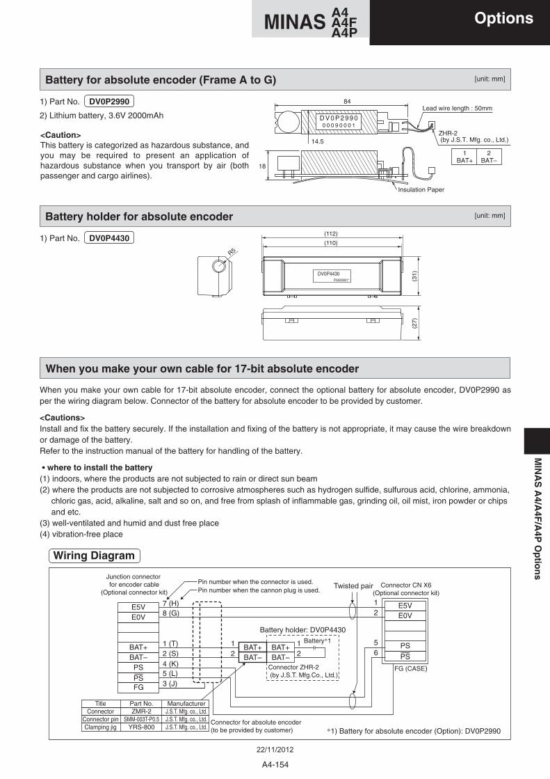
MIN
AS
A4/A
4F/A
4PO
ptio
ns
When you make your own cable for 17-bit absolute encoder, connect the optional battery for absolute encoder, DV0P2990 as per the wiring diagram below. Connector of the battery for absolute encoder to be provided by customer.
<Cautions>Install and fix the battery securely. If the installation and fixing of the battery is not appropriate, it may cause the wire breakdown or damage of the battery.Refer to the instruction manual of the battery for handling of the battery.
• where to install the battery(1) indoors, where the products are not subjected to rain or direct sun beam(2) where the products are not subjected to corrosive atmospheres such as hydrogen sulfide, sulfurous acid, chlorine, ammonia, chloric gas, acid, alkaline, salt and so on, and free from splash of inflammable gas, grinding oil, oil mist, iron powder or chips and etc.(3) well-ventilated and humid and dust free place(4) vibration-free place
When you make your own cable for 17-bit absolute encoder
Battery for absolute encoder (Frame A to G)
Battery holder: DV0P4430
1) Part No. DV0P2990
2) Lithium battery, 3.6V 2000mAh
<Caution>This battery is categorized as hazardous substance, and you may be required to present an application of hazardous substance when you transport by air (both passenger and cargo airlines).
1) Part No. DV0P4430
D V 0 P 2 9 9 00 0 0 9 0 0 0 1
84
18
Insulation Paper
Lead wire length : 50mm
ZHR-2 (by J.S.T. Mfg. co., Ltd.)
1BAT+
2BAT–
14.5
E5V 7 (H)8 (G)
1 (T) 12
1 Battery*1
Connector ZHR-2 (by J.S.T. Mfg.Co., Ltd.)
2
12
562 (S)
4 (K)5 (L)3 (J)
FG (CASE)
Connector CN X6(Optional connector kit)
E0V
BAT+BAT–
BAT+
Twisted pairPin number when the connector is used.
*1) Battery for absolute encoder (Option): DV0P2990Connector for absolute encoder(to be provided by customer)
Junction connector for encoder cable
(Optional connector kit) Pin number when the cannon plug is used.
BAT–BAT+BAT–
PS
PSFG
E5VE0V
PS
PS
Title Part No. ManufacturerConnector ZMR-2 J.S.T. Mfg. co., Ltd.
Connector pin SMM-003T-P0.5 J.S.T. Mfg. co., Ltd.Clamping jig YRS-800 J.S.T. Mfg. co., Ltd.
Wiring Diagram
Battery holder for absolute encoder
DV0P4430P04090001*
R5
(112)
(110)
(31)
(27)
[unit: mm]
[unit: mm]
A4-154
A4MINAS A4FA4P
Options
22/11/2012
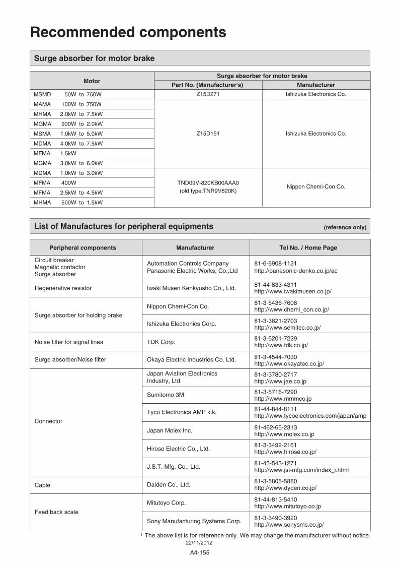
Surge absorber for motor brake
Surge absorber for motor brake
Part No. (Manufacturer's) Manufacturer
Z15D271 Ishizuka Electronics Co.
Z15D151
TND09V-820KB00AAA0(old type:TNR9V820K)
Ishizuka Electronics Co.
Nippon Chemi-Con Co.
Motor
MSMD 50W to 750W
MAMA 100W to 750W
MHMA 2.0kW to 7.5kW
MGMA 900W to 2.0kW
MSMA 1.0kW to 5.0kW
MDMA 4.0kW to 7.5kW
MFMA 1.5kW
MGMA 3.0kW to 6.0kW
MDMA 1.0kW to 3.0kW
MFMA 400W
MFMA 2.5kW to 4.5kW
MHMA 500W to 1.5kW
List of Manufactures for peripheral equipments (reference only)
Manufacturer
Okaya Electric Industries Co. Ltd.
Nippon Chemi-Con Co.
Ishizuka Electronics Corp.
Japan Aviation Electronics Industry, Ltd.
Sumitomo 3M
Tyco Electronics AMP k.k,
TDK Corp.
Iwaki Musen Kenkyusho Co., Ltd.
Peripheral components
Surge absorber/Noise filter
Surge absorber for holding brake
Connector
Noise filter for signal lines
Regenerative resistor
Tel No. / Home Page
81-3-4544-7030http://www.okayatec.co.jp/
81-3-5436-7608http://www.chemi_con.co.jp/
Automation Controls Company Panasonic Electric Works, Co.,Ltd
Circuit breakerMagnetic contactorSurge absorber
81-3-3621-2703http://www.semitec.co.jp/
81-6-6908-1131http://panasonic-denko.co.jp/ac
81-3-3780-2717http://www.jae.co.jp
81-3-5716-7290http://www.mmmco.jp
81-44-844-8111http://www.tycoelectronics.com/japan/amp
81-3-5805-5880 http://www.dyden.co.jp/
81-462-65-2313http://www.molex.co.jp
81-3-5201-7229http://www.tdk.co.jp/
81-44-833-4311http://www.iwakimusen.co.jp/
Daiden Co., Ltd.
Japan Molex Inc.
Cable
81-45-543-1271http://www.jst-mfg.com/index_i.htmlJ.S.T. Mfg. Co., Ltd.
81-44-813-5410 http://www.mitutoyo.co.jpMitutoyo Corp.
81-3-3490-3920http://www.sonysms.co.jp/Sony Manufacturing Systems Corp.
81-3-3492-2161http://www.hirose.co.jp/Hirose Electric Co., Ltd.
* The above list is for reference only. We may change the manufacturer without notice.
Feed back scale
Recommended components
A4-155
22/11/2012
Recommended