MIMU22BL–Integration Guide
Doc: MIMU22BL-integration-guide.pdf
Revision: 1.12
Release Date: 02 May, 2019
w w w . i n e r t i a l e l e m e n t s . c o m i n f o @ i n e r t i a l e l e m e n t s . c o m
Page 1
MIMU22BL
Integration Guide
Revision 1.12
© 2019, GT Silicon Pvt Ltd, Kanpur, India
Tel: +91-700-741-0690
Email: [email protected]
URL: www.inertialelements.com
www.gt-silicon.com
Registered Office:
GT Silicon Pvt Ltd
LIG 1398, Avas Vikas 3,
PO NSI, Kalyanpur
Kanpur (UP), India, PIN – 208017
MIMU22BL–Integration Guide
Doc: MIMU22BL-integration-guide.pdf
Revision: 1.12
Release Date: 02 May, 2019
w w w . i n e r t i a l e l e m e n t s . c o m i n f o @ i n e r t i a l e l e m e n t s . c o m
Page 2
Revision History
Revision Revision Date Updates
1.0 06 January 2018 Initial version
1.1 23 January 2018 Minor typographical corrections
1.2 2February 2018 Few commands updated
1.3 5February 2018 This integration document is for firmware version 1.2 where the
sampling frequency is changed from 200 Hz to 250 Hz and the heading
is being calculated based on Magnetometer of IMU # 3 instead of fused
Magnetometer data.
1.4 22 March 2018 Change the command for “High precision IMU with Pressure and
Magnetometer #3 data” to avoid complexity. This is an alternate
command and also backward compatible. Upgraded Output mode
Sample table andminor typographical corrections
1.5 15June 2018 Change in the “Output Osmium Data” data format.
1.6 21 June 2018 Few typographical corrections
1.7 18July 2018 Few minor changes and typographical corrections
1.8
08 Aug 2018 Included USB driver installation
Modified hexadecimal number representation (0x)
Checksum computation explained in Appendix IV (1)
Command’s acknowledgement packet explained in Appendix IV(2)
1.9 11 Aug 2018 Added figures for board features and IMU orientations.
1.10 14 Aug 2018 Included feature list
Included examples of converting hex values to actual values

MIMU22BL–Integration Guide
Doc: MIMU22BL-integration-guide.pdf
Revision: 1.12
Release Date: 02 May, 2019
w w w . i n e r t i a l e l e m e n t s . c o m i n f o @ i n e r t i a l e l e m e n t s . c o m
Page 3
1.11 22 Aug 2018 Few minor changes
1.12 02 May 2019 Explanation of timestamp
MIMU22BL–Integration Guide
Doc: MIMU22BL-integration-guide.pdf
Revision: 1.12
Release Date: 02 May, 2019
w w w . i n e r t i a l e l e m e n t s . c o m i n f o @ i n e r t i a l e l e m e n t s . c o m
Page 4
Purpose & Scope
This document describes the data processing flow in MIMU22BL. It also describes communication
protocol using which one can access and control the data and the processing at various stages, through an
external application platform.
Please refer following documents also for specific details:
1. Datasheet –ICM-20948
2. 32-bit AVR Microcontorller Specification
MIMU22BL–Integration Guide
Doc: MIMU22BL-integration-guide.pdf
Revision: 1.12
Release Date: 02 May, 2019
w w w . i n e r t i a l e l e m e n t s . c o m i n f o @ i n e r t i a l e l e m e n t s . c o m
Page 5
Introduction
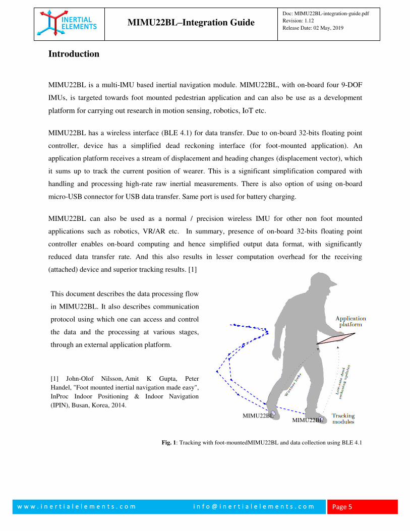
MIMU22BL is a multi-IMU based inertial navigation module. MIMU22BL, with on-board four 9-DOF
IMUs, is targeted towards foot mounted pedestrian application and can also be use as a development
platform for carrying out research in motion sensing, robotics, IoT etc.
MIMU22BL has a wireless interface (BLE 4.1) for data transfer. Due to on-board 32-bits floating point
controller, device has a simplified dead reckoning interface (for foot-mounted application). An
application platform receives a stream of displacement and heading changes (displacement vector), which
it sums up to track the current position of wearer. This is a significant simplification compared with
handling and processing high-rate raw inertial measurements. There is also option of using on-board
micro-USB connector for USB data transfer. Same port is used for battery charging.
MIMU22BL can also be used as a normal / precision wireless IMU for other non foot mounted
applications such as robotics, VR/AR etc. In summary, presence of on-board 32-bits floating point
controller enables on-board computing and hence simplified output data format, with significantly
reduced data transfer rate. And this also results in lesser computation overhead for the receiving
(attached) device and superior tracking results. [1]
Fig. 1: Tracking with foot-mountedMIMU22BL and data collection using BLE 4.1
MIMU22BL
MIMU22BL
This document describes the data processing flow
in MIMU22BL. It also describes communication
protocol using which one can access and control
the data and the processing at various stages,
through an external application platform.
[1] John-Olof Nilsson, Amit K Gupta, Peter
Handel, "Foot mounted inertial navigation made easy",
InProc Indoor Positioning & Indoor Navigation
(IPIN), Busan, Korea, 2014.
MIMU22BL–Integration Guide
Doc: MIMU22BL-integration-guide.pdf
Revision: 1.12
Release Date: 02 May, 2019
w w w . i n e r t i a l e l e m e n t s . c o m i n f o @ i n e r t i a l e l e m e n t s . c o m
Page 6
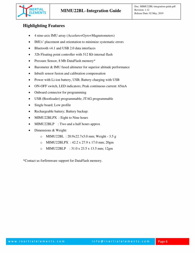
Highlighting Features
4 nine-axis IMU array (Accelero+Gyro+Magnetometers)
IMUs’ placement and orientation to minimize systematic errors
Bluetooth v4.1 and USB 2.0 data interfaces
32b Floating point controller with 512 Kb internal flash
Pressure Sensor, 8 Mb DataFlash memory*
Barometer & IMU fused altimeter for superior altitude performance
Inbuilt sensor fusion and calibration compensation
Power with Li-ion battery, USB; Battery charging with USB
ON-OFF switch, LED indicators; Peak continuous current: 65mA
Onboard connector for programming
USB (Bootloader) programmable; JTAG programmable
Single board; Low profile
Rechargeable battery; Battery backup:
MIMU22BLPX : Eight to Nine hours
MIMU22BLP : Two and a half hours approx
Dimensions & Weight:
o MIMU22BL : 20.9x22.7x5.0 mm; Weight - 3.5 g
o MIMU22BLPX : 42.2 x 27.9 x 17.0 mm; 20gm
o MIMU22BLP : 31.0 x 23.5 x 13.5 mm; 12gm
*Contact us forfirmware support for DataFlash memory.
MIMU22BL–Integration Guide
Doc: MIMU22BL-integration-guide.pdf
Revision: 1.12
Release Date: 02 May, 2019
w w w . i n e r t i a l e l e m e n t s . c o m i n f o @ i n e r t i a l e l e m e n t s . c o m
Page 7
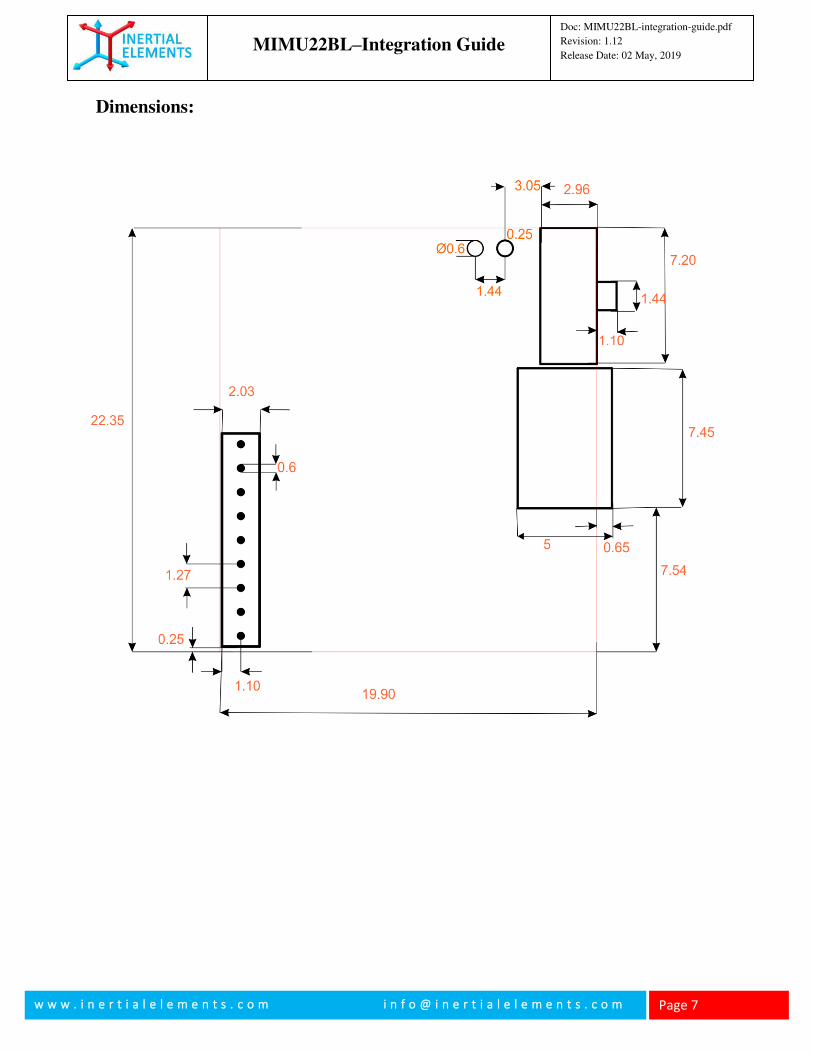
Dimensions:
MIMU22BL–Integration Guide
Doc: MIMU22BL-integration-guide.pdf
Revision: 1.12
Release Date: 02 May, 2019
w w w . i n e r t i a l e l e m e n t s . c o m i n f o @ i n e r t i a l e l e m e n t s . c o m
Page 8
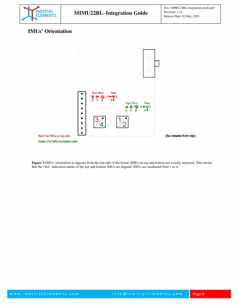
IMUs’ Orientation
Figure 3 IMUs’ orientation as appears from the top side of the board. IMUs on top and bottom are exactly mirrored. This means that the “dot” indication marks of the top and bottom IMUs are aligned. IMUs are numbered from 1 to 4.
MIMU22BL–Integration Guide
Doc: MIMU22BL-integration-guide.pdf
Revision: 1.12
Release Date: 02 May, 2019
w w w . i n e r t i a l e l e m e n t s . c o m i n f o @ i n e r t i a l e l e m e n t s . c o m
Page 9
USB Driver Installation
One must install USB driver for data communication with PC (or any data acquisition system).
The on-board microcontroller Atmel AT32UC3C0512C offers USB 2.0 port. The USB connector on
MIMU22BL board is directly connected with the USB pins of the controller.
The USB port of the microcontroller has been programmed in the firmware as CDC Virtual COM, so that
it appears as a UART port (COM port) when connected with a PC. Hence installation of a corresponding
USB driver on PC (or data acquisition system) is required, if the board has to communicate with the PC
through its USB port.
(i) Download the Atmel USB driver file and its installation manual from
https://www.inertialelements.com/resources.html.
(ii) Go to Computer management/Device Manager/Port and update the driver as instructed in the
manual. Though the installation process is demonstrated for Windows 10, it is same for the
previous versions of Windows OS.
For video demo, please visit the support page from www.inertialelements.com and check the video with
title “How to update USB Driver for MIMU22BL”
MIMU22BL–Integration Guide
Doc: MIMU22BL-integration-guide.pdf
Revision: 1.12
Release Date: 02 May, 2019
w w w . i n e r t i a l e l e m e n t s . c o m i n f o @ i n e r t i a l e l e m e n t s . c o m
Page 10
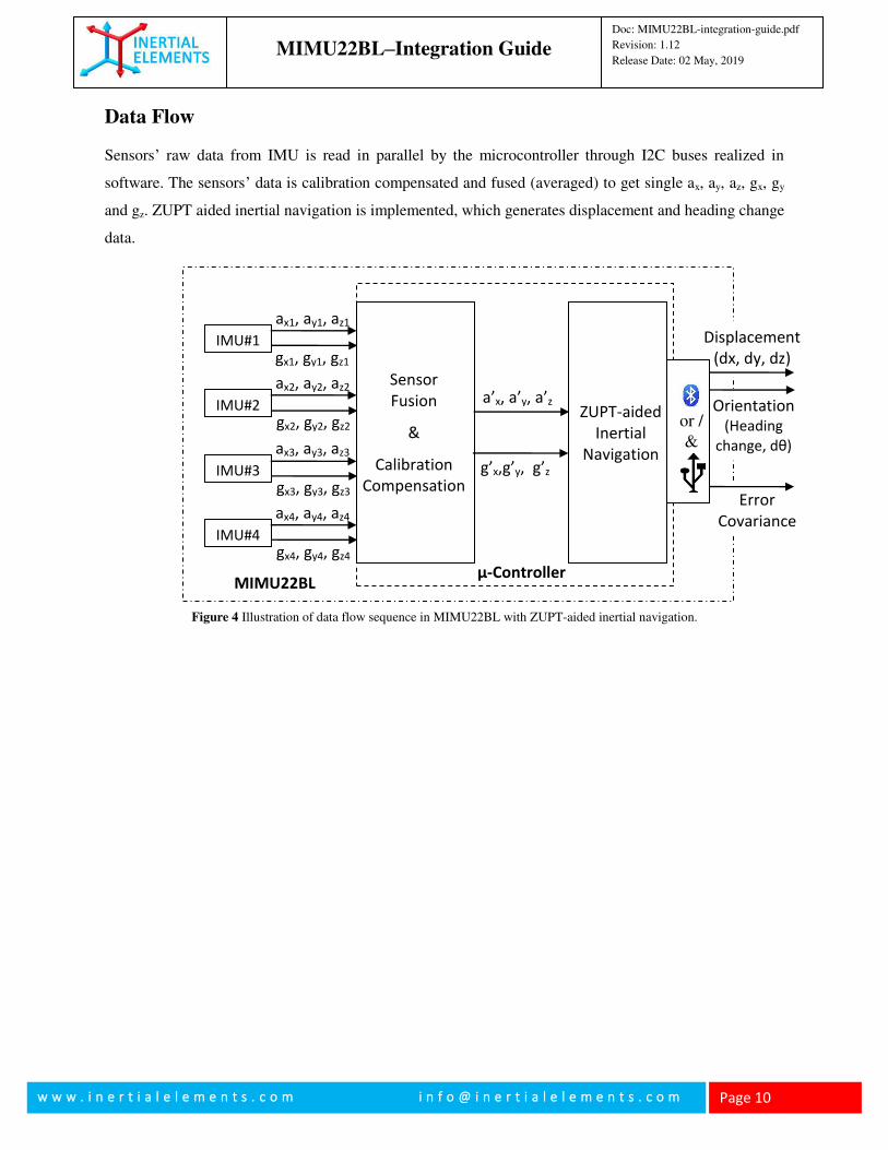
Data Flow
Sensors’ raw data from IMU is read in parallel by the microcontroller through I2C buses realized in
software. The sensors’ data is calibration compensated and fused (averaged) to get single ax, ay, az, gx, gy
and gz. ZUPT aided inertial navigation is implemented, which generates displacement and heading change
data.
Error
Covariance
Orientation
(Heading
change, dθ)
Displacement
(dx, dy, dz)
g’x,g’y, g’z
a’x, a’y, a’z
gx1, gy1, gz1
ax1, ay1, az1
IMU#1
gx2, gy2, gz2
ax2, ay2, az2
IMU#2
gx3, gy3, gz3
ax3, ay3, az3
IMU#3
gx4, gy4, gz4
ax4, ay4, az4
IMU#4
Sensor
Fusion
&
Calibration
Compensation
ZUPT-aided
Inertial
Navigation
MIMU22BL µ-Controller
or /
&
Figure 4 Illustration of data flow sequence in MIMU22BL with ZUPT-aided inertial navigation.
MIMU22BL–Integration Guide
Doc: MIMU22BL-integration-guide.pdf
Revision: 1.12
Release Date: 02 May, 2019
w w w . i n e r t i a l e l e m e n t s . c o m i n f o @ i n e r t i a l e l e m e n t s . c o m
Page 11
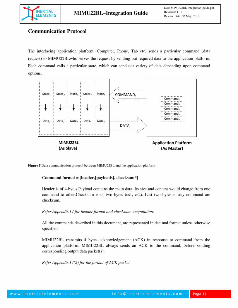
Communication Protocol
The interfacing application platform (Computer, Phone, Tab etc) sends a particular command (data
request) to MIMU22BLwho serves the request by sending out required data to the application platform.
Each command calls a particular state, which can send out variety of data depending upon command
options.
Command format = [header,{payloads}, checksum*]
Header is of 4-bytes.Payload contains the main data. Its size and content would change from one
command to other.Checksum is of two bytes (cs1, cs2). Last two bytes in any command are
checksum.
Refer Appendix IV for header format and checksum computation.
All the commands described in this document, are represented in decimal format unless otherwise
specified.
MIMU22BL transmits 4 bytes acknowledgement (ACK) in response to command from the
application platform. MIMU22BL always sends an ACK to the command, before sending
corresponding output data packet(s).
Refer Appendix IV(2) for the format of ACK packet.
Figure 5 Data communication protocol between MIMU22BL and the application platform
COMMANDi
oblu
(As Slave) Application Platform
(As Master)
Command1
Command2
Command3
Command4
Command5
DATAi
State1 State2 State3 State4 State5
Data1 Data2 Data3 Data4 Data5
MIMU22BL
MIMU22BL–Integration Guide
Doc: MIMU22BL-integration-guide.pdf
Revision: 1.12
Release Date: 02 May, 2019
w w w . i n e r t i a l e l e m e n t s . c o m i n f o @ i n e r t i a l e l e m e n t s . c o m
Page 12
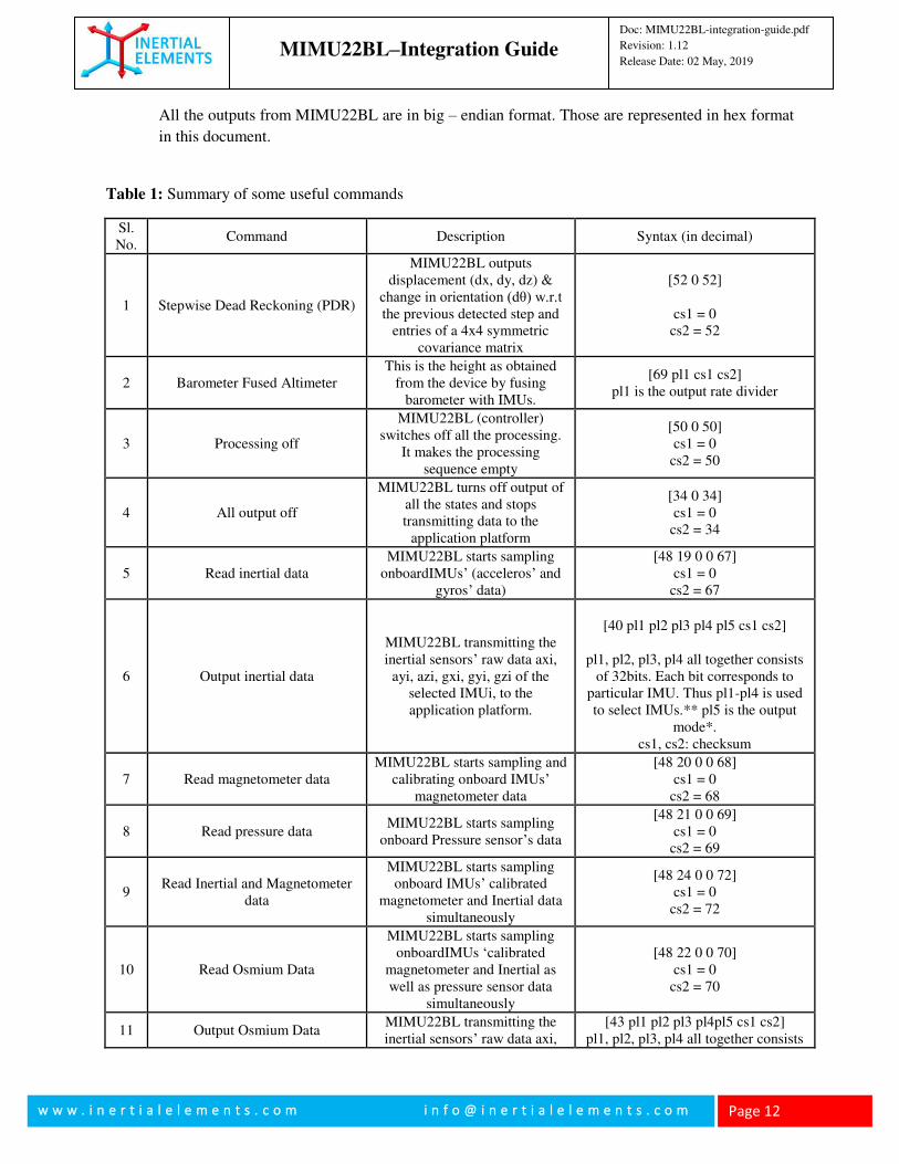
All the outputs from MIMU22BL are in big – endian format. Those are represented in hex format
in this document.
Table 1: Summary of some useful commands
Sl. No.
Command Description Syntax (in decimal)
1 Stepwise Dead Reckoning (PDR)
MIMU22BL outputs displacement (dx, dy, dz) &
change in orientation (dθ) w.r.t the previous detected step and
entries of a 4x4 symmetric covariance matrix
[52 0 52]
cs1 = 0 cs2 = 52
2 Barometer Fused Altimeter This is the height as obtained
from the device by fusing barometer with IMUs.
[69 pl1 cs1 cs2] pl1 is the output rate divider
3 Processing off
MIMU22BL (controller) switches off all the processing.
It makes the processing sequence empty
[50 0 50] cs1 = 0
cs2 = 50
4 All output off
MIMU22BL turns off output of all the states and stops transmitting data to the
application platform
[34 0 34] cs1 = 0
cs2 = 34
5 Read inertial data MIMU22BL starts sampling
onboardIMUs’ (acceleros’ and gyros’ data)
[48 19 0 0 67] cs1 = 0
cs2 = 67
6 Output inertial data
MIMU22BL transmitting the inertial sensors’ raw data axi,
ayi, azi, gxi, gyi, gzi of the selected IMUi, to the application platform.
[40 pl1 pl2 pl3 pl4 pl5 cs1 cs2]
pl1, pl2, pl3, pl4 all together consists
of 32bits. Each bit corresponds to particular IMU. Thus pl1-pl4 is used to select IMUs.** pl5 is the output
mode*. cs1, cs2: checksum
7 Read magnetometer data MIMU22BL starts sampling and
calibrating onboard IMUs’ magnetometer data
[48 20 0 0 68] cs1 = 0
cs2 = 68
8 Read pressure data MIMU22BL starts sampling
onboard Pressure sensor’s data
[48 21 0 0 69] cs1 = 0
cs2 = 69
9 Read Inertial and Magnetometer
data
MIMU22BL starts sampling onboard IMUs’ calibrated
magnetometer and Inertial data simultaneously
[48 24 0 0 72] cs1 = 0
cs2 = 72
10 Read Osmium Data
MIMU22BL starts sampling onboardIMUs ‘calibrated
magnetometer and Inertial as well as pressure sensor data
simultaneously
[48 22 0 0 70] cs1 = 0
cs2 = 70
11 Output Osmium Data MIMU22BL transmitting the inertial sensors’ raw data axi,
[43 pl1 pl2 pl3 pl4pl5 cs1 cs2] pl1, pl2, pl3, pl4 all together consists
MIMU22BL–Integration Guide
Doc: MIMU22BL-integration-guide.pdf
Revision: 1.12
Release Date: 02 May, 2019
w w w . i n e r t i a l e l e m e n t s . c o m i n f o @ i n e r t i a l e l e m e n t s . c o m
Page 13
ayi, azi, gxi, gyi, gzi, magnetometer raw data mxi,
myi, mzi and temperature data of the selected IMUs and
Pressure and temperature data from Pressure sensor to the
application platform.
of 32bits. Each bit corresponds to particular IMU. Thus pl1-pl4 is used to select IMUs.** pl5 is the output
mode*. cs1, cs2: checksum
12 Read IMU temperature data MIMU22BL starts reading internal temperature of the
onboard IMUs’
[53 0 53] cs1 = 0
cs2 = 53
13 Output IMU temperature data
MIMU22BL starts transmitting temperature of the selected
onboard IMU(s), to the application platform.
[40 pl1 pl2 pl3 pl4 pl5 cs1 cs2]
pl1, pl2, pl3 and pl4 are same as in
the command for state OUTPUT_IMU_RD**. pl5 is the
output mode* byte, cs1, cs2: checksum
14 High precision IMU (Normal
IMU)
MIMU22BL outputs g’x, g’y, g’z, a’x, a’y, a’z (ref Fig 2 and
Fig 3) after calibration compensation and sensor fusion.
[64 pl1 cs1 cs2] pl1 = output mode* cs1, cs2: checksum
15 High precision IMU with bias
estimation
MIMU22BL outputs g’x, g’y, g’z, a’x, a’y, a’z after
calibration compensation and sensor fusion along with the
estimated bias.
[65 pl1 cs1 cs2] pl1 = output mode* cs1, cs2: checksum
16 High precision IMU
withMagnetometer #3 data
MIMU22BL outputs g’x, g’y, g’z, a’x, a’y, a’z (ref Fig 2 and
Fig 3) after calibration compensation and sensor fusion
along with calibratedMagnetometer #3 data
(m’x, m’y,m’z)
57 pl1 cs1 cs2 pl1 is the output mask mode$, cs1,
cs2: checksum
17 High precision IMU with Pressure
data
MIMU22BL outputs g’x, g’y, g’z, a’x, a’y, a’z (ref Fig 2 and
Fig 3) after calibration compensation and sensor fusion
along with pressure data.
57 pl1 cs1 cs2 pl1 is the output mask mode*, cs1,
cs2: checksum
18 Output High precision IMU with Pressure andMagnetometer #3
data
MIMU22BL outputs g’x, g’y, g’z, a’x, a’y, a’z (ref Fig 2 and
Fig 3) after calibration compensation and sensor fusion
along with calibratedMagnetometer #3 data
(m’x, m’y,m’z) and pressure data.
[49 22 16 00 00 00 00 00 00 00 87] [33 08 13 52 187 00 00 00 00 pl2 cs1
cs2]
pl2 = output mode* cs1, cs2: checksum
19 Request output of state Requests the state connected to
the state ID to be output.
[32 pl1 pl2 cs1 cs2] pl1 = state ID
pl2 = output mode* cs1, cs2: checksum
20 Request output of multiple states Requests the multiple states
connected to the state IDs to be output.
[33 pl1 pl2 pl3 pl4 pl5 pl6 pl7 pl8 pl9 cs1 cs2]
pl1-pl8 = state ID pl9 = output mode*
MIMU22BL–Integration Guide
Doc: MIMU22BL-integration-guide.pdf
Revision: 1.12
Release Date: 02 May, 2019
w w w . i n e r t i a l e l e m e n t s . c o m i n f o @ i n e r t i a l e l e m e n t s . c o m
Page 14
cs1, cs2: checksum
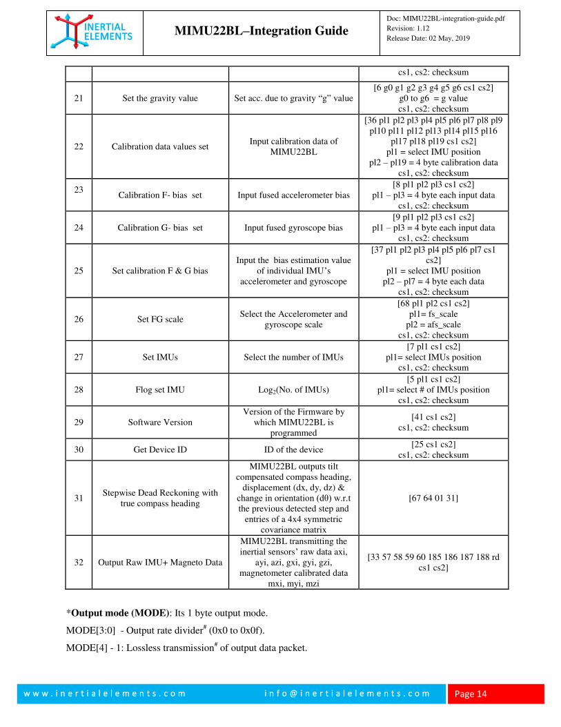
21 Set the gravity value Set acc. due to gravity “g” value [6 g0 g1 g2 g3 g4 g5 g6 cs1 cs2]
g0 to g6 = g value cs1, cs2: checksum
22 Calibration data values set Input calibration data of
MIMU22BL
[36 pl1 pl2 pl3 pl4 pl5 pl6 pl7 pl8 pl9 pl10 pl11 pl12 pl13 pl14 pl15 pl16
pl17 pl18 pl19 cs1 cs2] pl1 = select IMU position
pl2 – pl19 = 4 byte calibration data cs1, cs2: checksum
23
Calibration F- bias set Input fused accelerometer bias [8 pl1 pl2 pl3 cs1 cs2]
pl1 – pl3 = 4 byte each input data cs1, cs2: checksum
24 Calibration G- bias set
Input fused gyroscope bias [9 pl1 pl2 pl3 cs1 cs2]
pl1 – pl3 = 4 byte each input data cs1, cs2: checksum
25 Set calibration F & G bias Input the bias estimation value
of individual IMU’s accelerometer and gyroscope
[37 pl1 pl2 pl3 pl4 pl5 pl6 pl7 cs1 cs2]
pl1 = select IMU position pl2 – pl7 = 4 byte each data
cs1, cs2: checksum
26 Set FG scale Select the Accelerometer and
gyroscope scale
[68 pl1 pl2 cs1 cs2] pl1= fs_scale
pl2 = afs_scale cs1, cs2: checksum
27 Set IMUs Select the number of IMUs [7 pl1 cs1 cs2]
pl1= select IMUs position cs1, cs2: checksum
28 Flog set IMU Log2(No. of IMUs) [5 pl1 cs1 cs2]
pl1= select # of IMUs position cs1, cs2: checksum
29 Software Version Version of the Firmware by
which MIMU22BL is programmed
[41 cs1 cs2] cs1, cs2: checksum
30 Get Device ID ID of the device [25 cs1 cs2]
cs1, cs2: checksum
31 Stepwise Dead Reckoning with
true compass heading
MIMU22BL outputs tilt compensated compass heading,
displacement (dx, dy, dz) & change in orientation (dθ) w.r.t the previous detected step and
entries of a 4x4 symmetric covariance matrix
[67 64 01 31]
32 Output Raw IMU+ Magneto Data
MIMU22BL transmitting the inertial sensors’ raw data axi,
ayi, azi, gxi, gyi, gzi, magnetometer calibrated data
mxi, myi, mzi
[33 57 58 59 60 185 186 187 188 rd cs1 cs2]
*Output mode (MODE): Its 1 byte output mode.
MODE[3:0] - Output rate divider# (0x0 to 0x0f).
MODE[4] - 1: Lossless transmission# of output data packet.

MIMU22BL–Integration Guide
Doc: MIMU22BL-integration-guide.pdf
Revision: 1.12
Release Date: 02 May, 2019
w w w . i n e r t i a l e l e m e n t s . c o m i n f o @ i n e r t i a l e l e m e n t s . c o m
Page 15
0: Not a lossless transmission of output data packet. (Recommended for Precision IMU mode)
MODE[5] - This bit is meaningful only if output rate divider$ (RD) is set to 0.
1: MIMU22BL generates only a single output data packet in response to a command
0: MIMU22BL does not generate any output data packet.
MODE[6] – 1: Output contains raw data of each IMU, i.e. acc and gyro data from each sensor
0: Raw IMU data disabled
MODE[7] – 1: Temperature data of all the 32 IMUs
0: Temperature data disabled
Table 2: Output mode Sample
Output mode
(Binary Bits)
Rate
divider
MODE[3:0]
Lossless*1
MODE[4]
Single time
output
MODE[5]
Raw IMU
MODE[6]
Raw IMU
Temperature
MODE[7]
Other
Output*1
Decimal
Equivalent
0000 0001 -
0000 1111 1-15 X X X X ✓
1-15
0100 0001 –
0100 1111 1-15 X X ✓ X X
65-79
0101 0001 –
0101 1111 1-15 ✓ X ✓ X X
81-95
1001 0001 –
1001 1111 1-15 ✓ X X ✓ X
145-159
1000 0001-
1000 1111 1-15 X X X ✓ X
129-143
0110 0000 0 X ✓ ✓ X X 96
00010001-
00011111 1-15 ✓ X X X ✓
17-31
00100000 0 X ✓ X X ✓ 32
00110000
(No use) 0 ✓ ✓ X X ✓
48
*1: For lossless transmission, each data packet must be acknowledged by the application platform. In this
mode, MIMU22BL transmits next data packet, only on receiving acknowledgement for the previous one.
The data acknowledgement (“PKG ACK”) packet is different from command acknowledgement (ACK
received in response to command). Refer Appendix II(4) for details about PKG ACK.
*2: Other output includes all data output commands where output mode is used except “Output inertial
data” and “Output IMU temperature data”.
MIMU22BL–Integration Guide
Doc: MIMU22BL-integration-guide.pdf
Revision: 1.12
Release Date: 02 May, 2019
w w w . i n e r t i a l e l e m e n t s . c o m i n f o @ i n e r t i a l e l e m e n t s . c o m
Page 16
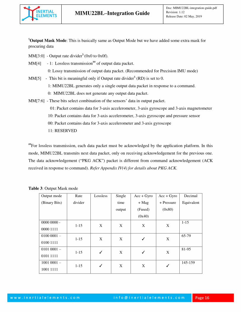
$Output Mask Mode: This is basically same as Output Mode but we have added some extra mask for
procuring data
MM[3:0] - Output rate divider$ (0x0 to 0x0f).
MM[4] - 1: Lossless transmission## of output data packet.
0: Lossy transmission of output data packet. (Recommended for Precision IMU mode)
MM[5] - This bit is meaningful only if Output rate divider$ (RD) is set to 0.
1: MIMU22BL generates only a single output data packet in response to a command.
0: MIMU22BL does not generate any output data packet.
MM[7:6] - These bits select combination of the sensors’ data in output packet.
01: Packet contains data for 3-axis accelerometer, 3-axis gyroscope and 3-axis magnetometer
10: Packet contains data for 3-axis accelerometer, 3-axis gyroscope and pressure sensor
00: Packet contains data for 3-axis accelerometer and 3-axis gyroscope
11: RESERVED
##For lossless transmission, each data packet must be acknowledged by the application platform. In this
mode, MIMU22BL transmits next data packet, only on receiving acknowledgement for the previous one.
The data acknowledgement (“PKG ACK”) packet is different from command acknowledgement (ACK
received in response to command). Refer Appendix IV(4) for details about PKG ACK.
Table 3: Output Mask mode
Output mode
(Binary Bits)
Rate
divider
Lossless Single
time
output
Acc + Gyro
+ Mag
(Fused)
(0x40)
Acc + Gyro
+ Pressure
(0x80)
Decimal
Equivalent
0000 0000 -
0000 1111 1-15 X X X X
1-15
0100 0001 –
0100 1111 1-15 X X ✓ X
65-79
0101 0001 –
0101 1111 1-15 ✓ X ✓ X
81-95
1001 0001 –
1001 1111 1-15 ✓ X X ✓
145-159
MIMU22BL–Integration Guide
Doc: MIMU22BL-integration-guide.pdf
Revision: 1.12
Release Date: 02 May, 2019
w w w . i n e r t i a l e l e m e n t s . c o m i n f o @ i n e r t i a l e l e m e n t s . c o m
Page 17
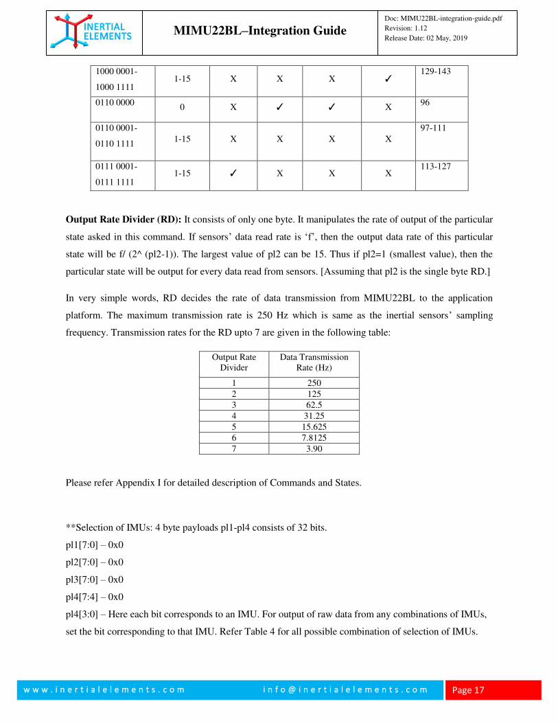
1000 0001-
1000 1111 1-15 X X X ✓
129-143
0110 0000 0 X ✓ ✓ X
96
0110 0001-
0110 1111 1-15 X X X X
97-111
0111 0001-
0111 1111 1-15 ✓ X X X
113-127
Output Rate Divider (RD): It consists of only one byte. It manipulates the rate of output of the particular
state asked in this command. If sensors’ data read rate is ‘f’, then the output data rate of this particular
state will be f/ (2^ (pl2-1)). The largest value of pl2 can be 15. Thus if pl2=1 (smallest value), then the
particular state will be output for every data read from sensors. [Assuming that pl2 is the single byte RD.]
In very simple words, RD decides the rate of data transmission from MIMU22BL to the application
platform. The maximum transmission rate is 250 Hz which is same as the inertial sensors’ sampling
frequency. Transmission rates for the RD upto 7 are given in the following table:
Output Rate Divider
Data Transmission Rate (Hz)
1 250
2 125
3 62.5
4 31.25
5 15.625
6 7.8125
7 3.90
Please refer Appendix I for detailed description of Commands and States.
**Selection of IMUs: 4 byte payloads pl1-pl4 consists of 32 bits.
pl1[7:0] – 0x0
pl2[7:0] – 0x0
pl3[7:0] – 0x0
pl4[7:4] – 0x0
pl4[3:0] – Here each bit corresponds to an IMU. For output of raw data from any combinations of IMUs,
set the bit corresponding to that IMU. Refer Table 4 for all possible combination of selection of IMUs.
MIMU22BL–Integration Guide
Doc: MIMU22BL-integration-guide.pdf
Revision: 1.12
Release Date: 02 May, 2019
w w w . i n e r t i a l e l e m e n t s . c o m i n f o @ i n e r t i a l e l e m e n t s . c o m
Page 18
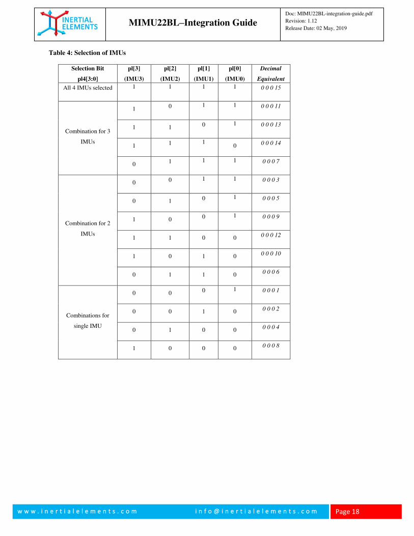
Table 4: Selection of IMUs
Selection Bit
pl4[3:0]
pl[3]
(IMU3)
pl[2]
(IMU2)
pl[1]
(IMU1)
pl[0]
(IMU0)
Decimal
Equivalent
All 4 IMUs selected 1
1
1
1
0 0 0 15
Combination for 3
IMUs
1 0 1
1
0 0 0 11
1 1 0 1
0 0 0 13
1 1 1
0 0 0 0 14
0 1 1
1
0 0 0 7
Combination for 2
IMUs
0 0 1
1
0 0 0 3
0 1 0 1
0 0 0 5
1 0 0 1
0 0 0 9
1 1 0 0 0 0 0 12
1 0 1 0 0 0 0 10
0 1 1 0 0 0 0 6
Combinations for
single IMU
0 0 0 1
0 0 0 1
0 0 1 0 0 0 0 2
0 1 0 0 0 0 0 4
1 0 0 0 0 0 0 8
MIMU22BL–Integration Guide
Doc: MIMU22BL-integration-guide.pdf
Revision: 1.12
Release Date: 02 May, 2019
w w w . i n e r t i a l e l e m e n t s . c o m i n f o @ i n e r t i a l e l e m e n t s . c o m
Page 19
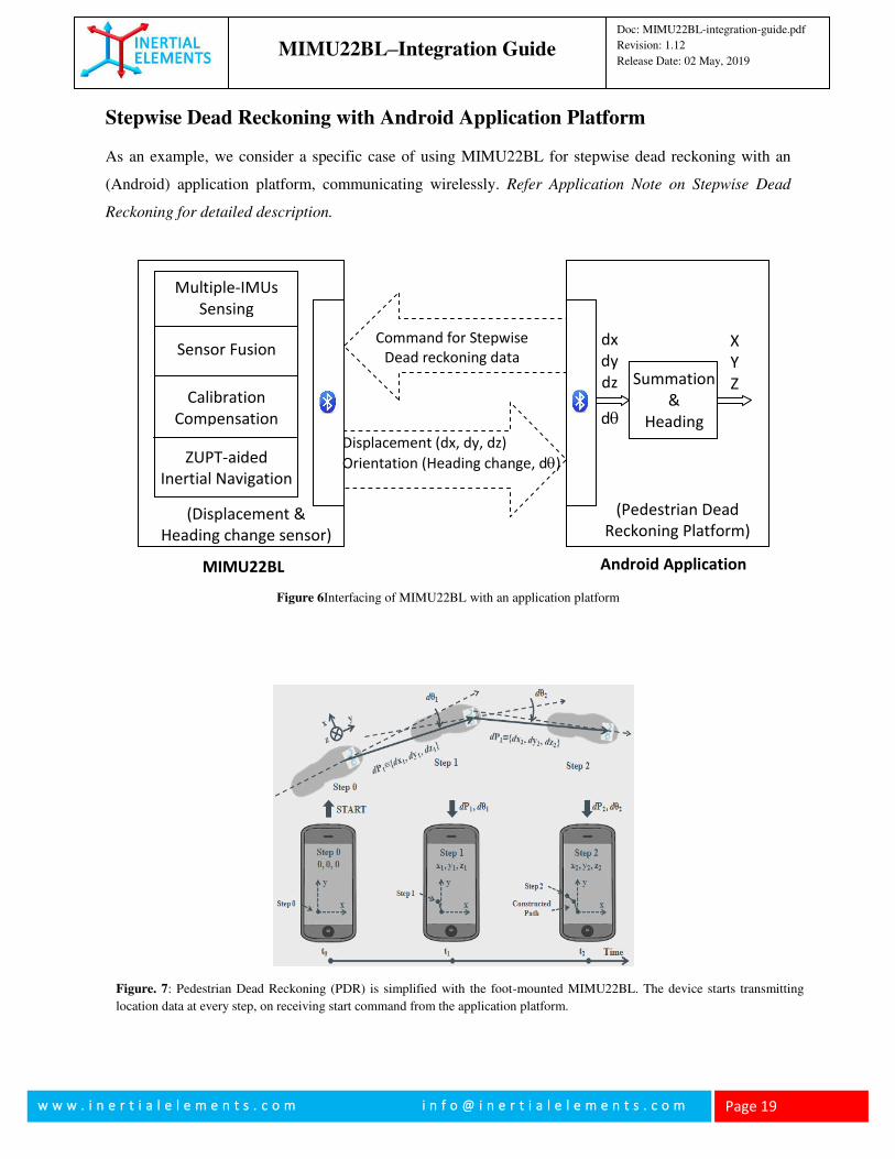
Stepwise Dead Reckoning with Android Application Platform
As an example, we consider a specific case of using MIMU22BL for stepwise dead reckoning with an
(Android) application platform, communicating wirelessly. Refer Application Note on Stepwise Dead
Reckoning for detailed description.
Command for Stepwise
Dead reckoning data X
Y
Z
dx
dy
dz Summation
&
Heading
MIMU22BL
(Pedestrian Dead
Reckoning Platform)
Sensor Fusion
(Displacement &
Heading change sensor)
Calibration
Compensation
ZUPT-aided
Inertial Navigation
Multiple-IMUs
Sensing
Displacement (dx, dy, dz)
Orientation (Heading change, d)
d
Figure 6Interfacing of MIMU22BL with an application platform
Android Application
Figure. 7: Pedestrian Dead Reckoning (PDR) is simplified with the foot-mounted MIMU22BL. The device starts transmitting
location data at every step, on receiving start command from the application platform.
MIMU22BL–Integration Guide
Doc: MIMU22BL-integration-guide.pdf
Revision: 1.12
Release Date: 02 May, 2019
w w w . i n e r t i a l e l e m e n t s . c o m i n f o @ i n e r t i a l e l e m e n t s . c o m
Page 20
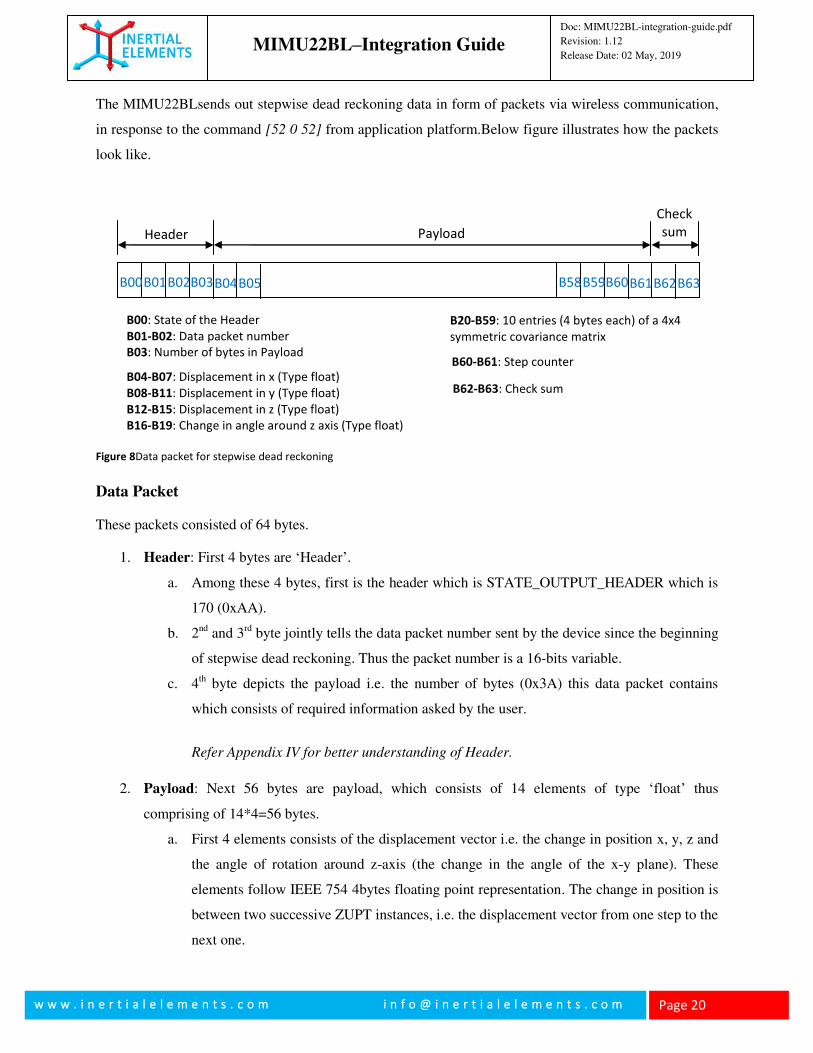
The MIMU22BLsends out stepwise dead reckoning data in form of packets via wireless communication,
in response to the command [52 0 52] from application platform.Below figure illustrates how the packets
look like.
Data Packet
These packets consisted of 64 bytes.
1. Header: First 4 bytes are ‘Header’.
a. Among these 4 bytes, first is the header which is STATE_OUTPUT_HEADER which is
170 (0xAA).
b. 2nd and 3rd byte jointly tells the data packet number sent by the device since the beginning
of stepwise dead reckoning. Thus the packet number is a 16-bits variable.
c. 4th byte depicts the payload i.e. the number of bytes (0x3A) this data packet contains
which consists of required information asked by the user.
Refer Appendix IV for better understanding of Header.
2. Payload: Next 56 bytes are payload, which consists of 14 elements of type ‘float’ thus
comprising of 14*4=56 bytes.
a. First 4 elements consists of the displacement vector i.e. the change in position x, y, z and
the angle of rotation around z-axis (the change in the angle of the x-y plane). These
elements follow IEEE 754 4bytes floating point representation. The change in position is
between two successive ZUPT instances, i.e. the displacement vector from one step to the
next one.
B00 B01 B02 B03 B04 B05 B58 B59 B60 B61 B62 B63
Header Payload
Check
sum
B00: State of the Header
B01-B02: Data packet number
B03: Number of bytes in Payload
B04-B07: Displacement in x (Type float)
B08-B11: Displacement in y (Type float)
B12-B15: Displacement in z (Type float)
B16-B19: Change in angle around z axis (Type float)
B20-B59: 10 entries (4 bytes each) of a 4x4
symmetric covariance matrix
B62-B63: Check sum
B60-B61: Step counter
Figure 8Data packet for stepwise dead reckoning
MIMU22BL–Integration Guide
Doc: MIMU22BL-integration-guide.pdf
Revision: 1.12
Release Date: 02 May, 2019
w w w . i n e r t i a l e l e m e n t s . c o m i n f o @ i n e r t i a l e l e m e n t s . c o m
Page 21
b. The other 10 elements of the payload are used to form the covariance matrix, which is a
4x4 symmetric matrix, thus 10 elements. These elements denote the estimated error value
for the displacement vector.
3. Step Counter: Next two bytes consists of step counter, which is a counter taking record of ZUPT
instances observed. This is essentially number of times MIMU22BL detects steps, i.e. the
standstill moment in one’s stride. Therefore the step counter is the number of steps detected by
MIMU22BL when used as shoe-mounted PDR sensor for pedestrian tracking.
4. Checksum: The last two bytes of 64 bytes consist of checksum which is sum of all the bytes
received prior to these. These are used to cross-check correctness of the data transferred. Refer
Appendix IV to know more about Checksum.
Rotation in Application Platform
MIMU22BL transmits tracking data with respect to its own frame which itself is not fixed with
respect to the user’s global reference frame. Therefore the data should undergo rotational
transformation before being presented to the end user in a global reference frame. (Here global
refers to the coordinate axis in which the system is initialized.)
The first four bytes of Payload are the position and heading change vector (displacement vector),
i.e. dx, dy, dz, dθ (dθ is the change in angle of rotation about z-axis or yaw). These values are the
output from the device at every ZUPT instance. As mentioned earlier, each set of displacement
vector describes movement between two successive steps. The position and heading change
vector are with reference to the coordinate frame of last ZUPT instance.
The ‘dθ’ corresponds to the deviation in the orientation of MIMU22BL. It is rotation of the x-y
plane about the z-axis, and z-axis is always aligned with the gravity. The data is thus used for
updating the orientation of the system, and obtaining the global reference frame. The two
dimensions of displacement vector (dx, dy) are transformed to the global frame by applying
rotation and thus (x,y) in the global frame is obtained. As we do not consider any change in
alignment in z-axis, updating the z coordinate is performed by simply adding present dz to the z
obtained for previous ZUPT.

MIMU22BL–Integration Guide
Doc: MIMU22BL-integration-guide.pdf
Revision: 1.12
Release Date: 02 May, 2019
w w w . i n e r t i a l e l e m e n t s . c o m i n f o @ i n e r t i a l e l e m e n t s . c o m
Page 22
Thus x,y,zcoordinates in the global reference frame are obtained at every ZUPT.
Details are covered in Application Note. You may also refer Appendix II for a piece of an
example Python script for better understanding of implementation.
MIMU22BL–Integration Guide
Doc: MIMU22BL-integration-guide.pdf
Revision: 1.12
Release Date: 02 May, 2019
w w w . i n e r t i a l e l e m e n t s . c o m i n f o @ i n e r t i a l e l e m e n t s . c o m
Page 23
Appendix I
1. State: Stepwise Dead Reckoning (SWDR)
Command: [52 0 52]
MIMU22BL sends out data packet for stepwise dead reckoning in response to this command [2].
Use this command only through Bluetooth. It will not work through USB.
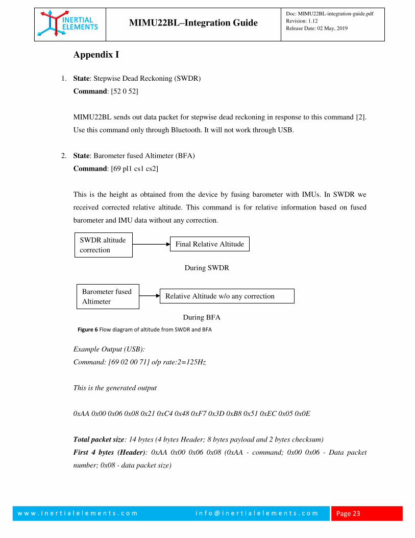
2. State: Barometer fused Altimeter (BFA)
Command: [69 pl1 cs1 cs2]
This is the height as obtained from the device by fusing barometer with IMUs. In SWDR we
received corrected relative altitude. This command is for relative information based on fused
barometer and IMU data without any correction.
Example Output (USB):
Command: [69 02 00 71] o/p rate:2=125Hz
This is the generated output
0xAA 0x00 0x06 0x08 0x21 0xC4 0x48 0xF7 0x3D 0xB8 0x51 0xEC 0x05 0x0E
Total packet size: 14 bytes (4 bytes Header; 8 bytes payload and 2 bytes checksum)
First 4 bytes (Header): 0xAA 0x00 0x06 0x08 (0xAA - command; 0x00 0x06 - Data packet
number; 0x08 - data packet size)
During SWDR
SWDR altitude
correction Final Relative Altitude
Barometer fused
Altimeter Relative Altitude w/o any correction
During BFA
Figure 6 Flow diagram of altitude from SWDR and BFA
MIMU22BL–Integration Guide
Doc: MIMU22BL-integration-guide.pdf
Revision: 1.12
Release Date: 02 May, 2019
w w w . i n e r t i a l e l e m e n t s . c o m i n f o @ i n e r t i a l e l e m e n t s . c o m
Page 24
Next 8 bytes (Payload): First 4 bytes (unsigned integer) of payload are time stamp; Next 4 bytes
are altitude data in float (IEEE 754 floating point representation).
Checksum:0x05 0x0E
3. State: Processing Off
Command: [50 0 50]
MIMU22BL terminates all the ongoing processing in response to this command. This is soft OFF
button. There would not be any output to this command. On giving this command there will be
only a command acknowledgement. This command is recommended as soon as the user finishes
collecting data preceded by (4) i.e All Output Off command.
4. State: All Output Off
Command: [34 0 34]
If this command is passed to the system, then the transmission of data packets would stop. But
there will be no change in the process going on inside, that all the functions would be running as
it is, just the thing is values would not be output. There would not be any output to this command.
On giving this command there will be only a command acknowledgement. This command is also
recommended as soon as the user finishes collecting data followed by (3) i.e “Processing Off”
command.
5. State: Read Inertial Data
Command: [48 19 pl1 cs1 cs2]
This command creates enabling conditions for the command Output Inertial Data, i.e. (6).
Therefore this command must be run just before (6). There would not be any output to this
command. On giving this command there will be only a command acknowledgement.
cs1, cs2: Two bytes checksum
Example:
Recommended for USB:
MIMU22BL–Integration Guide
Doc: MIMU22BL-integration-guide.pdf
Revision: 1.12
Release Date: 02 May, 2019
w w w . i n e r t i a l e l e m e n t s . c o m i n f o @ i n e r t i a l e l e m e n t s . c o m
Page 25
[48 19 0 67]
No output for this command.
6. State: Output Inertial Data
Command: [40 pl1 pl2 pl3 pl4 pl5 cs1, cs2]
MIMU22BLoutputs IMU sensors’ readings in response to this command.
Here pl1, pl2, pl3 and pl4 constitute one byte each. These are used for selecting IMUs. Consider
the pl1, pl2, pl3 and pl4 all together constitute 4 bytes i.e. 32 bits, where each bit corresponds to
one of the 32 IMUs.
Consider if we want to select the first 4 IMUs we want to have the 4 LSBs to be 1 which can be
made by having pl4 be 15 (binary: 00001111) and all the others be 0. Thus [40 0 0 0 15 1 0 56] is
a sample command selecting the first four IMUs for getting the raw inertial data. pl5 here is the
output mode byte.
Here the output consists of [axi, ayi, azi, gxi, gyi, gzi] for each IMU selected, as in Fig 2. As each of
the values corresponds to 2 bytes, thus the output is of 12 bytes for each IMU.
Note: (5) i.e. command “Read Inertial Data” command must be run before this command.
Also note that MIMU22BL has only four IMUs. However the s/w can support upto thirty two
IMUs.
cs1, cs2: Two bytes checksum
Example:
Set of commands to obtain data packets containing 4 accelerometers' and 4 gyroscopes' data:
Recommended for USB:
[48 19 0 67]
[40 0 0 0 15 65 0 120] (o/p data rate:1 = 250 Hz)
Recommended for Bluetooth
MIMU22BL–Integration Guide
Doc: MIMU22BL-integration-guide.pdf
Revision: 1.12
Release Date: 02 May, 2019
w w w . i n e r t i a l e l e m e n t s . c o m i n f o @ i n e r t i a l e l e m e n t s . c o m
Page 26
[48 19 0 67]
[40 0 0 0 15 68 0 124] (o/p data rate: 4* = 25 Hz)
*output rate divider is 64+ Output rate divider.
Here are the example data packets containing 4 accelerometers' and 4 gyroscopes' data, obtained
as a result of above set of commands (USB):
0xAA 0x00 0x01 0x34 0x21 0xC4 0x48 0xF7 0x00 0x6E 0x00 0x54 0x07 0x57 0xFF 0xE4 0x00
0x05 0x00 0x17 0xFF 0x98 0xFF 0x81 0xF7 0x6A 0xFF 0xD2 0x00 0x13 0x00 0x11 0x00 0x7E
0x00 0x57 0x07 0xD9 0xFF 0xF6 0x00 0x0B 0xFF 0xEF 0xFF 0x9A 0xFF 0x8C 0xF7 0x60 0xFF
0xF6 0xFF 0xF0 0xFF 0xFC 0x1C 0x8C
0xAA 0x00 0x02 0x34 0x21 0xC5 0x35 0xEC 0x00 0x6E 0x00 0x54 0x07 0x57 0xFF 0xE2 0x00
0x04 0x00 0x16 0xFF 0x90 0xFF 0x7F 0xF7 0x68 0xFF 0xD4 0x00 0x13 0x00 0x11 0x00 0x68
0x00 0x56 0x07 0xD0 0xFF 0xF5 0x00 0x0A 0xFF 0xF0 0xFF 0x8E 0xFF 0x91 0xF7 0x54 0xFF
0xF2 0xFF 0xF2 0xFF 0xFE 0x1C 0x2E
Description of the above packet:
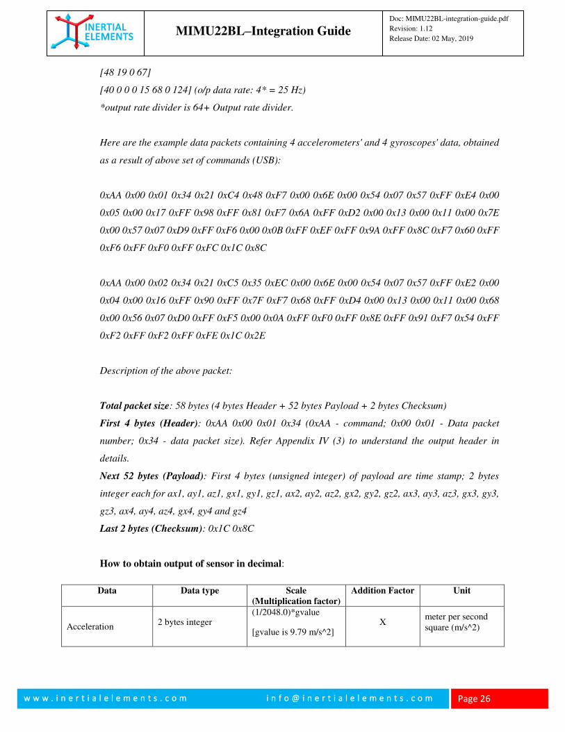
Total packet size: 58 bytes (4 bytes Header + 52 bytes Payload + 2 bytes Checksum)
First 4 bytes (Header): 0xAA 0x00 0x01 0x34 (0xAA - command; 0x00 0x01 - Data packet
number; 0x34 - data packet size). Refer Appendix IV (3) to understand the output header in
details.
Next 52 bytes (Payload): First 4 bytes (unsigned integer) of payload are time stamp; 2 bytes
integer each for ax1, ay1, az1, gx1, gy1, gz1, ax2, ay2, az2, gx2, gy2, gz2, ax3, ay3, az3, gx3, gy3,
gz3, ax4, ay4, az4, gx4, gy4 and gz4
Last 2 bytes (Checksum): 0x1C 0x8C
How to obtain output of sensor in decimal:
Data Data type Scale
(Multiplication factor)
Addition Factor Unit
Acceleration 2 bytes integer
(1/2048.0)*gvalue
[gvalue is 9.79 m/s^2] X
meter per second square (m/s^2)
MIMU22BL–Integration Guide
Doc: MIMU22BL-integration-guide.pdf
Revision: 1.12
Release Date: 02 May, 2019
w w w . i n e r t i a l e l e m e n t s . c o m i n f o @ i n e r t i a l e l e m e n t s . c o m
Page 27
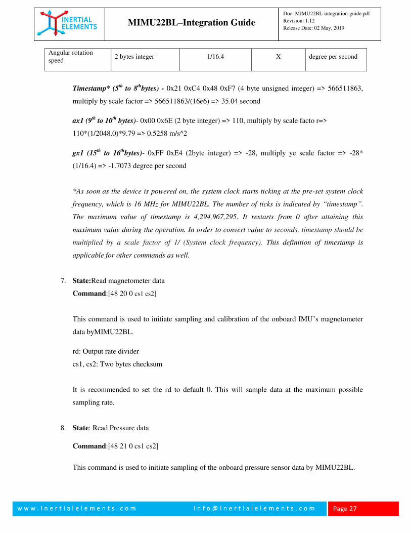
Angular rotation speed
2 bytes integer 1/16.4 X degree per second
Timestamp* (5th
to 8th
bytes) - 0x21 0xC4 0x48 0xF7 (4 byte unsigned integer) => 566511863,
multiply by scale factor => 566511863/(16e6) => 35.04 second
ax1 (9th
to 10th
bytes)- 0x00 0x6E (2 byte integer) => 110, multiply by scale facto r=>
110*(1/2048.0)*9.79 => 0.5258 m/s^2
gx1 (15th
to 16th
bytes)- 0xFF 0xE4 (2byte integer) => -28, multiply ye scale factor => -28*
(1/16.4) => -1.7073 degree per second
*As soon as the device is powered on, the system clock starts ticking at the pre-set system clock
frequency, which is 16 MHz for MIMU22BL. The number of ticks is indicated by “timestamp”.
The maximum value of timestamp is 4,294,967,295. It restarts from 0 after attaining this
maximum value during the operation. In order to convert value to seconds, timestamp should be
multiplied by a scale factor of 1/ (System clock frequency). This definition of timestamp is
applicable for other commands as well.
7. State:Read magnetometer data
Command:[48 20 0 cs1 cs2]
This command is used to initiate sampling and calibration of the onboard IMU’s magnetometer
data byMIMU22BL.
rd: Output rate divider
cs1, cs2: Two bytes checksum
It is recommended to set the rd to default 0. This will sample data at the maximum possible
sampling rate.
8. State: Read Pressure data
Command:[48 21 0 cs1 cs2]
This command is used to initiate sampling of the onboard pressure sensor data by MIMU22BL.
MIMU22BL–Integration Guide
Doc: MIMU22BL-integration-guide.pdf
Revision: 1.12
Release Date: 02 May, 2019
w w w . i n e r t i a l e l e m e n t s . c o m i n f o @ i n e r t i a l e l e m e n t s . c o m
Page 28
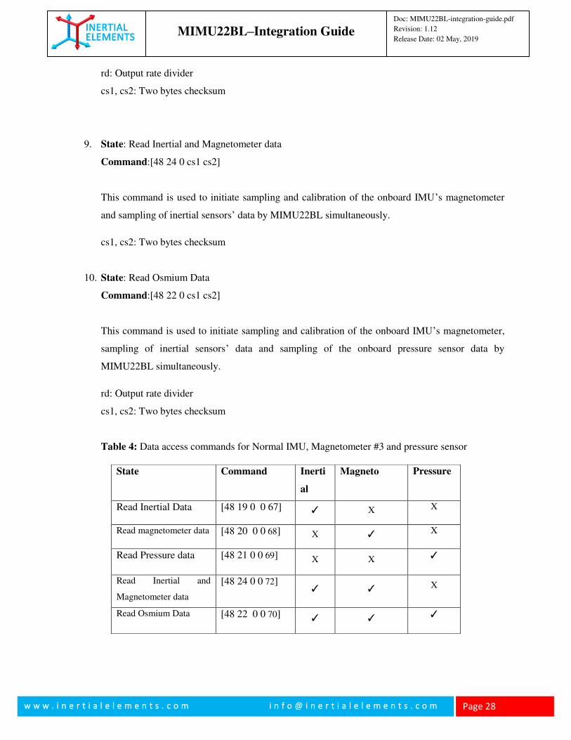
rd: Output rate divider
cs1, cs2: Two bytes checksum
9. State: Read Inertial and Magnetometer data
Command:[48 24 0 cs1 cs2]
This command is used to initiate sampling and calibration of the onboard IMU’s magnetometer
and sampling of inertial sensors’ data by MIMU22BL simultaneously.
cs1, cs2: Two bytes checksum
10. State: Read Osmium Data
Command:[48 22 0 cs1 cs2]
This command is used to initiate sampling and calibration of the onboard IMU’s magnetometer,
sampling of inertial sensors’ data and sampling of the onboard pressure sensor data by
MIMU22BL simultaneously.
rd: Output rate divider
cs1, cs2: Two bytes checksum
Table 4: Data access commands for Normal IMU, Magnetometer #3 and pressure sensor
State Command Inerti
al
Magneto Pressure
Read Inertial Data [48 19 0 0 67] ✓ X X
Read magnetometer data [48 20 0 0 68] X ✓ X
Read Pressure data [48 21 0 0 69] X X ✓
Read Inertial and
Magnetometer data
[48 24 0 0 72] ✓ ✓ X
Read Osmium Data [48 22 0 0 70] ✓ ✓ ✓
MIMU22BL–Integration Guide
Doc: MIMU22BL-integration-guide.pdf
Revision: 1.12
Release Date: 02 May, 2019
w w w . i n e r t i a l e l e m e n t s . c o m i n f o @ i n e r t i a l e l e m e n t s . c o m
Page 29
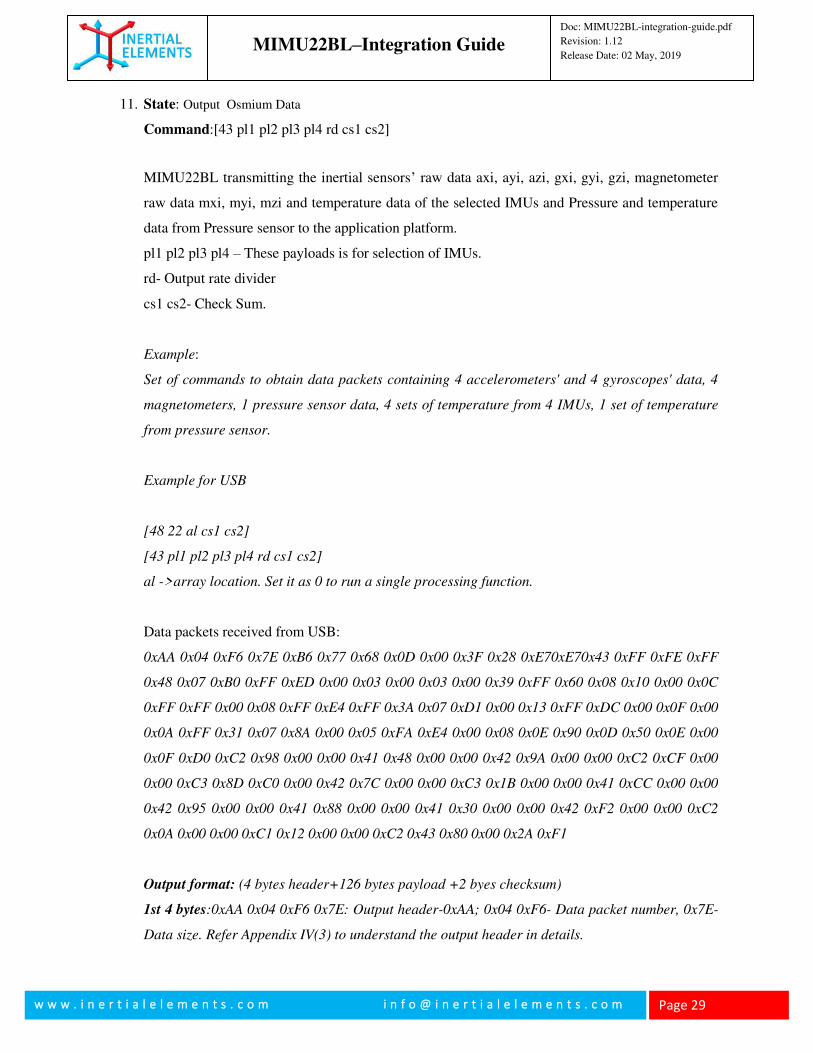
11. State: Output Osmium Data
Command:[43 pl1 pl2 pl3 pl4 rd cs1 cs2]
MIMU22BL transmitting the inertial sensors’ raw data axi, ayi, azi, gxi, gyi, gzi, magnetometer
raw data mxi, myi, mzi and temperature data of the selected IMUs and Pressure and temperature
data from Pressure sensor to the application platform.
pl1 pl2 pl3 pl4 – These payloads is for selection of IMUs.
rd- Output rate divider
cs1 cs2- Check Sum.
Example:
Set of commands to obtain data packets containing 4 accelerometers' and 4 gyroscopes' data, 4
magnetometers, 1 pressure sensor data, 4 sets of temperature from 4 IMUs, 1 set of temperature
from pressure sensor.
Example for USB
[48 22 al cs1 cs2]
[43 pl1 pl2 pl3 pl4 rd cs1 cs2]
al ->array location. Set it as 0 to run a single processing function.
Data packets received from USB:
0xAA 0x04 0xF6 0x7E 0xB6 0x77 0x68 0x0D 0x00 0x3F 0x28 0xE70xE70x43 0xFF 0xFE 0xFF
0x48 0x07 0xB0 0xFF 0xED 0x00 0x03 0x00 0x03 0x00 0x39 0xFF 0x60 0x08 0x10 0x00 0x0C
0xFF 0xFF 0x00 0x08 0xFF 0xE4 0xFF 0x3A 0x07 0xD1 0x00 0x13 0xFF 0xDC 0x00 0x0F 0x00
0x0A 0xFF 0x31 0x07 0x8A 0x00 0x05 0xFA 0xE4 0x00 0x08 0x0E 0x90 0x0D 0x50 0x0E 0x00
0x0F 0xD0 0xC2 0x98 0x00 0x00 0x41 0x48 0x00 0x00 0x42 0x9A 0x00 0x00 0xC2 0xCF 0x00
0x00 0xC3 0x8D 0xC0 0x00 0x42 0x7C 0x00 0x00 0xC3 0x1B 0x00 0x00 0x41 0xCC 0x00 0x00
0x42 0x95 0x00 0x00 0x41 0x88 0x00 0x00 0x41 0x30 0x00 0x00 0x42 0xF2 0x00 0x00 0xC2
0x0A 0x00 0x00 0xC1 0x12 0x00 0x00 0xC2 0x43 0x80 0x00 0x2A 0xF1
Output format: (4 bytes header+126 bytes payload +2 byes checksum)
1st 4 bytes:0xAA 0x04 0xF6 0x7E: Output header-0xAA; 0x04 0xF6- Data packet number, 0x7E-
Data size. Refer Appendix IV(3) to understand the output header in details.
MIMU22BL–Integration Guide
Doc: MIMU22BL-integration-guide.pdf
Revision: 1.12
Release Date: 02 May, 2019
w w w . i n e r t i a l e l e m e n t s . c o m i n f o @ i n e r t i a l e l e m e n t s . c o m
Page 30
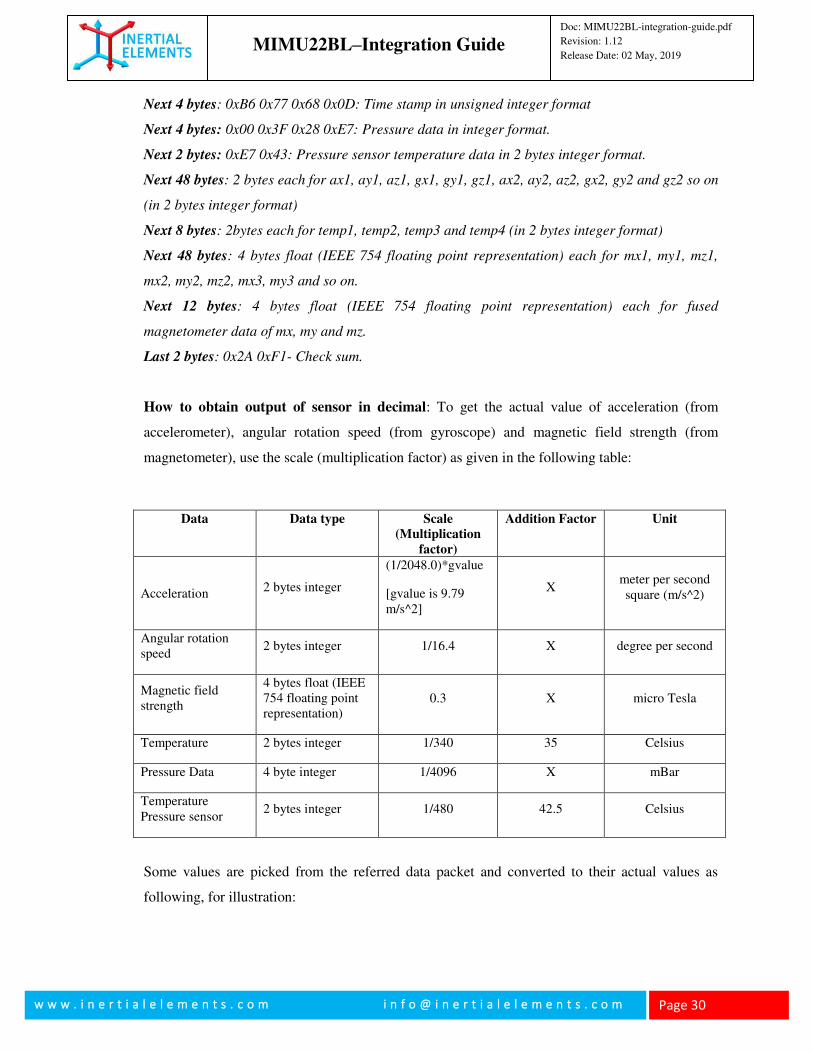
Next 4 bytes: 0xB6 0x77 0x68 0x0D: Time stamp in unsigned integer format
Next 4 bytes: 0x00 0x3F 0x28 0xE7: Pressure data in integer format.
Next 2 bytes: 0xE7 0x43: Pressure sensor temperature data in 2 bytes integer format.
Next 48 bytes: 2 bytes each for ax1, ay1, az1, gx1, gy1, gz1, ax2, ay2, az2, gx2, gy2 and gz2 so on
(in 2 bytes integer format)
Next 8 bytes: 2bytes each for temp1, temp2, temp3 and temp4 (in 2 bytes integer format)
Next 48 bytes: 4 bytes float (IEEE 754 floating point representation) each for mx1, my1, mz1,
mx2, my2, mz2, mx3, my3 and so on.
Next 12 bytes: 4 bytes float (IEEE 754 floating point representation) each for fused
magnetometer data of mx, my and mz.
Last 2 bytes: 0x2A 0xF1- Check sum.
How to obtain output of sensor in decimal: To get the actual value of acceleration (from
accelerometer), angular rotation speed (from gyroscope) and magnetic field strength (from
magnetometer), use the scale (multiplication factor) as given in the following table:
Data Data type Scale
(Multiplication
factor)
Addition Factor Unit
Acceleration 2 bytes integer
(1/2048.0)*gvalue
[gvalue is 9.79 m/s^2]
X meter per second square (m/s^2)
Angular rotation speed
2 bytes integer 1/16.4 X degree per second
Magnetic field strength
4 bytes float (IEEE 754 floating point representation)
0.3 X micro Tesla
Temperature 2 bytes integer 1/340 35 Celsius
Pressure Data 4 byte integer 1/4096 X mBar
Temperature Pressure sensor
2 bytes integer 1/480 42.5 Celsius
Some values are picked from the referred data packet and converted to their actual values as
following, for illustration:
MIMU22BL–Integration Guide
Doc: MIMU22BL-integration-guide.pdf
Revision: 1.12
Release Date: 02 May, 2019
w w w . i n e r t i a l e l e m e n t s . c o m i n f o @ i n e r t i a l e l e m e n t s . c o m
Page 31
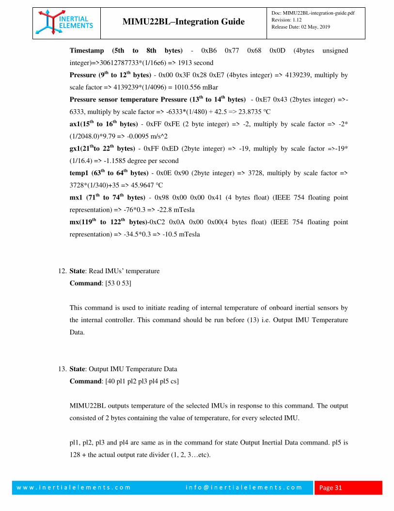
Timestamp (5th to 8th bytes) - 0xB6 0x77 0x68 0x0D (4bytes unsigned
integer)=>30612787733*(1/16e6) => 1913 second
Pressure (9th
to 12th
bytes) - 0x00 0x3F 0x28 0xE7 (4bytes integer) => 4139239, multiply by
scale factor => 4139239*(1/4096) = 1010.556 mBar
Pressure sensor temperature Pressure (13th
to 14th
bytes) - 0xE7 0x43 (2bytes integer) =>-
6333, multiply by scale factor => -6333*(1/480) + 42.5 => 23.8735 ℃
ax1(15th
to 16th
bytes) - 0xFF 0xFE (2 byte integer) => -2, multiply by scale factor => -2*
(1/2048.0)*9.79 => -0.0095 m/s^2
gx1(21th
to 22th
bytes) - 0xFF 0xED (2byte integer) => -19, multiply by scale factor =>-19*
(1/16.4) => -1.1585 degree per second
temp1 (63th
to 64th
bytes) - 0x0E 0x90 (2byte integer) => 3728, multiply by scale factor =>
3728*(1/340)+35 => 45.9647 ℃
mx1 (71th
to 74th
bytes) - 0x98 0x00 0x00 0x41 (4 bytes float) (IEEE 754 floating point
representation) => -76*0.3 => -22.8 mTesla
mx(119th
to 122th
bytes)-0xC2 0x0A 0x00 0x00(4 bytes float) (IEEE 754 floating point
representation) => -34.5*0.3 => -10.5 mTesla
12. State: Read IMUs’ temperature
Command: [53 0 53]
This command is used to initiate reading of internal temperature of onboard inertial sensors by
the internal controller. This command should be run before (13) i.e. Output IMU Temperature
Data.
13. State: Output IMU Temperature Data
Command: [40 pl1 pl2 pl3 pl4 pl5 cs]
MIMU22BL outputs temperature of the selected IMUs in response to this command. The output
consisted of 2 bytes containing the value of temperature, for every selected IMU.
pl1, pl2, pl3 and pl4 are same as in the command for state Output Inertial Data command. pl5 is
128 + the actual output rate divider (1, 2, 3…etc).
MIMU22BL–Integration Guide
Doc: MIMU22BL-integration-guide.pdf
Revision: 1.12
Release Date: 02 May, 2019
w w w . i n e r t i a l e l e m e n t s . c o m i n f o @ i n e r t i a l e l e m e n t s . c o m
Page 32
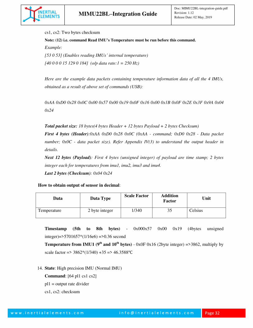
cs1, cs2: Two bytes checksum
Note: (12) i.e. command Read IMU’s Temperature must be run before this command.
Example:
[53 0 53] (Enables reading IMUs’ internal temperature)
[40 0 0 0 15 129 0 184] (o/p data rate:1 = 250 Hz)
Here are the example data packets containing temperature information data of all the 4 IMUs,
obtained as a result of above set of commands (USB):
0xAA 0xD0 0x28 0x0C 0x00 0x57 0x00 0x19 0x0F 0x16 0x00 0x1B 0x0F 0x2E 0x3F 0x9A 0x04
0x24
Total packet size: 18 bytes(4 bytes Header + 12 bytes Payload + 2 bytes Checksum)
First 4 bytes (Header):0xAA 0xD0 0x28 0x0C (0xAA - command; 0xD0 0x28 - Data packet
number; 0x0C - data packet size). Refer Appendix IV(3) to understand the output header in
details.
Next 12 bytes (Payload): First 4 bytes (unsigned integer) of payload are time stamp; 2 bytes
integer each for temperatures from imu1, imu2, imu3 and imu4.
Last 2 bytes (Checksum): 0x04 0x24
How to obtain output of sensor in decimal:
Data Data Type Scale Factor Addition
Factor Unit
Temperature 2 byte integer 1/340 35 Celsius
Timestamp (5th to 8th bytes) - 0x000x57 0x00 0x19 (4bytes unsigned
integer)=>5701657*(1/16e6) =>0.36 second
Temperature from IMU1 (9th
and 10th
bytes) - 0x0F 0x16 (2byte integer) =>3862, multiply by
scale factor => 3862*(1/340) +35 => 46.3588℃
14. State: High precision IMU (Normal IMU)
Command: [64 pl1 cs1 cs2]
pl1 = output rate divider
cs1, cs2: checksum
MIMU22BL–Integration Guide
Doc: MIMU22BL-integration-guide.pdf
Revision: 1.12
Release Date: 02 May, 2019
w w w . i n e r t i a l e l e m e n t s . c o m i n f o @ i n e r t i a l e l e m e n t s . c o m
Page 33
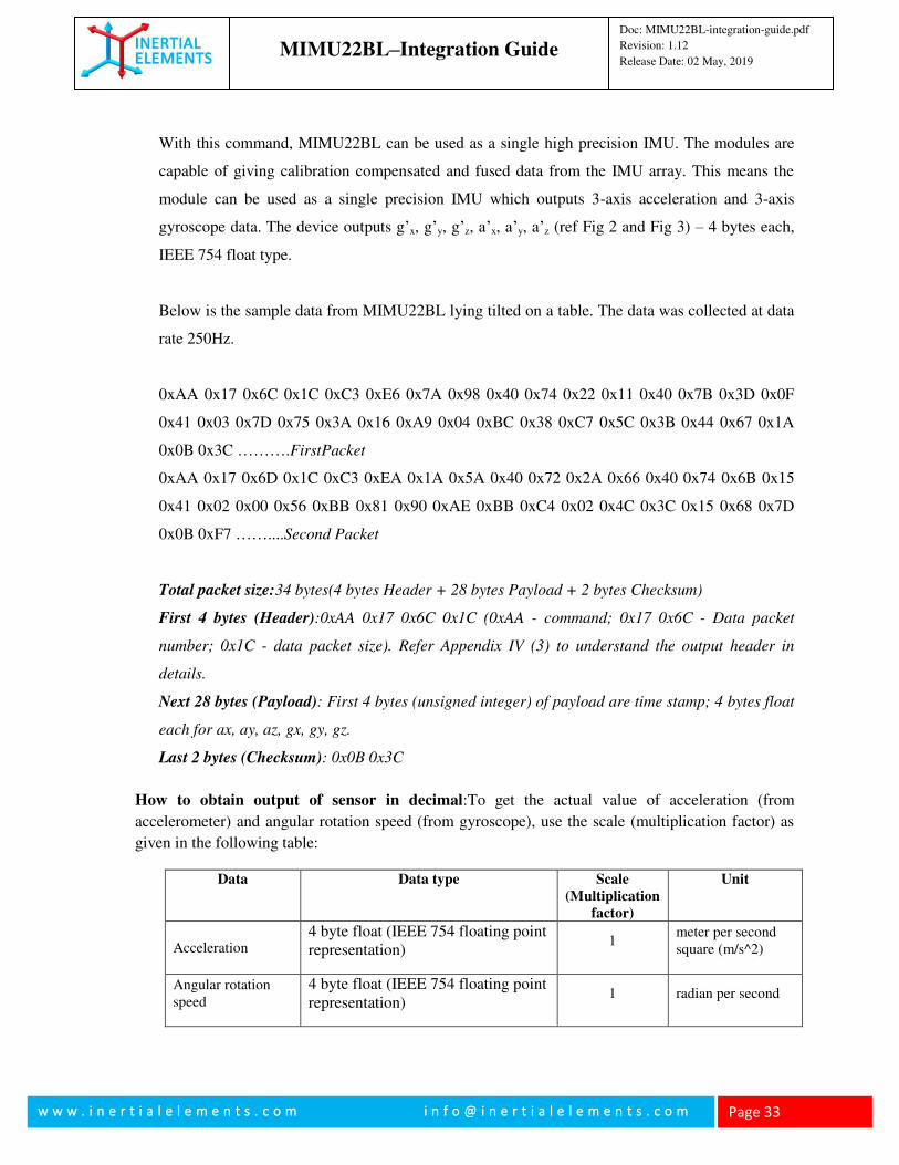
With this command, MIMU22BL can be used as a single high precision IMU. The modules are
capable of giving calibration compensated and fused data from the IMU array. This means the
module can be used as a single precision IMU which outputs 3-axis acceleration and 3-axis
gyroscope data. The device outputs g’x, g’y, g’z, a’x, a’y, a’z (ref Fig 2 and Fig 3) – 4 bytes each,
IEEE 754 float type.
Below is the sample data from MIMU22BL lying tilted on a table. The data was collected at data
rate 250Hz.
0xAA 0x17 0x6C 0x1C 0xC3 0xE6 0x7A 0x98 0x40 0x74 0x22 0x11 0x40 0x7B 0x3D 0x0F
0x41 0x03 0x7D 0x75 0x3A 0x16 0xA9 0x04 0xBC 0x38 0xC7 0x5C 0x3B 0x44 0x67 0x1A
0x0B 0x3C ……….FirstPacket
0xAA 0x17 0x6D 0x1C 0xC3 0xEA 0x1A 0x5A 0x40 0x72 0x2A 0x66 0x40 0x74 0x6B 0x15
0x41 0x02 0x00 0x56 0xBB 0x81 0x90 0xAE 0xBB 0xC4 0x02 0x4C 0x3C 0x15 0x68 0x7D
0x0B 0xF7 ……....Second Packet
Total packet size:34 bytes(4 bytes Header + 28 bytes Payload + 2 bytes Checksum)
First 4 bytes (Header):0xAA 0x17 0x6C 0x1C (0xAA - command; 0x17 0x6C - Data packet
number; 0x1C - data packet size). Refer Appendix IV (3) to understand the output header in
details.
Next 28 bytes (Payload): First 4 bytes (unsigned integer) of payload are time stamp; 4 bytes float
each for ax, ay, az, gx, gy, gz.
Last 2 bytes (Checksum): 0x0B 0x3C
How to obtain output of sensor in decimal:To get the actual value of acceleration (from
accelerometer) and angular rotation speed (from gyroscope), use the scale (multiplication factor) as
given in the following table:
Data Data type Scale
(Multiplication
factor)
Unit
Acceleration 4 byte float (IEEE 754 floating point representation)
1 meter per second square (m/s^2)
Angular rotation speed
4 byte float (IEEE 754 floating point representation)
1 radian per second
MIMU22BL–Integration Guide
Doc: MIMU22BL-integration-guide.pdf
Revision: 1.12
Release Date: 02 May, 2019
w w w . i n e r t i a l e l e m e n t s . c o m i n f o @ i n e r t i a l e l e m e n t s . c o m
Page 34
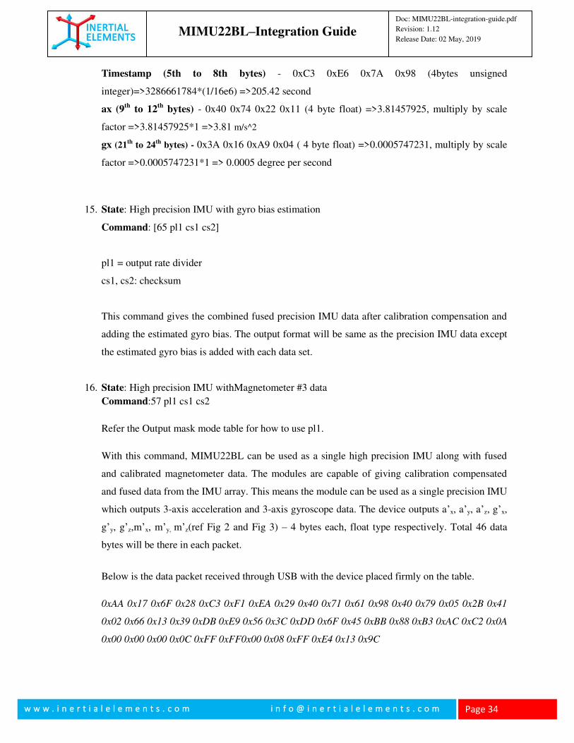
Timestamp (5th to 8th bytes) - 0xC3 0xE6 0x7A 0x98 (4bytes unsigned
integer)=>3286661784*(1/16e6) =>205.42 second
ax (9th
to 12th
bytes) - 0x40 0x74 0x22 0x11 (4 byte float) =>3.81457925, multiply by scale
factor =>3.81457925*1 =>3.81 m/s^2
gx (21th
to 24th
bytes) - 0x3A 0x16 0xA9 0x04 ( 4 byte float) =>0.0005747231, multiply by scale
factor =>0.0005747231*1 => 0.0005 degree per second
15. State: High precision IMU with gyro bias estimation
Command: [65 pl1 cs1 cs2]
pl1 = output rate divider
cs1, cs2: checksum
This command gives the combined fused precision IMU data after calibration compensation and
adding the estimated gyro bias. The output format will be same as the precision IMU data except
the estimated gyro bias is added with each data set.
16. State: High precision IMU withMagnetometer #3 data
Command:57 pl1 cs1 cs2
Refer the Output mask mode table for how to use pl1.
With this command, MIMU22BL can be used as a single high precision IMU along with fused
and calibrated magnetometer data. The modules are capable of giving calibration compensated
and fused data from the IMU array. This means the module can be used as a single precision IMU
which outputs 3-axis acceleration and 3-axis gyroscope data. The device outputs a’x, a’y, a’z, g’x,
g’y, g’z,m’x, m’y, m’z(ref Fig 2 and Fig 3) – 4 bytes each, float type respectively. Total 46 data
bytes will be there in each packet.
Below is the data packet received through USB with the device placed firmly on the table.
0xAA 0x17 0x6F 0x28 0xC3 0xF1 0xEA 0x29 0x40 0x71 0x61 0x98 0x40 0x79 0x05 0x2B 0x41
0x02 0x66 0x13 0x39 0xDB 0xE9 0x56 0x3C 0xDD 0x6F 0x45 0xBB 0x88 0xB3 0xAC 0xC2 0x0A
0x00 0x00 0x00 0x0C 0xFF 0xFF0x00 0x08 0xFF 0xE4 0x13 0x9C
MIMU22BL–Integration Guide
Doc: MIMU22BL-integration-guide.pdf
Revision: 1.12
Release Date: 02 May, 2019
w w w . i n e r t i a l e l e m e n t s . c o m i n f o @ i n e r t i a l e l e m e n t s . c o m
Page 35
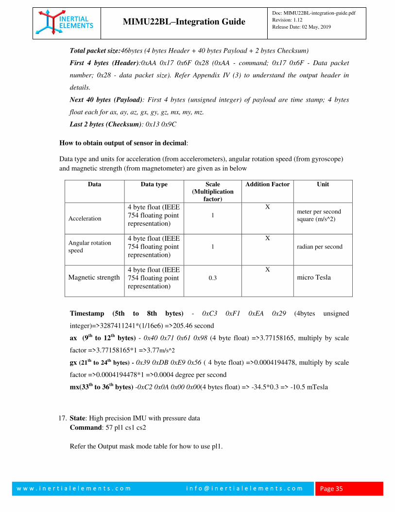
Total packet size:46bytes (4 bytes Header + 40 bytes Payload + 2 bytes Checksum)
First 4 bytes (Header):0xAA 0x17 0x6F 0x28 (0xAA - command; 0x17 0x6F - Data packet
number; 0x28 - data packet size). Refer Appendix IV (3) to understand the output header in
details.
Next 40 bytes (Payload): First 4 bytes (unsigned integer) of payload are time stamp; 4 bytes
float each for ax, ay, az, gx, gy, gz, mx, my, mz.
Last 2 bytes (Checksum): 0x13 0x9C
How to obtain output of sensor in decimal:
Data type and units for acceleration (from accelerometers), angular rotation speed (from gyroscope)
and magnetic strength (from magnetometer) are given as in below
Data Data type Scale
(Multiplication
factor)
Addition Factor Unit
Acceleration
4 byte float (IEEE 754 floating point representation)
1
X meter per second square (m/s^2)
Angular rotation speed
4 byte float (IEEE 754 floating point representation)
1
X
radian per second
Magnetic strength 4 byte float (IEEE 754 floating point representation)
0.3
X
micro Tesla
Timestamp (5th to 8th bytes) - 0xC3 0xF1 0xEA 0x29 (4bytes unsigned
integer)=>3287411241*(1/16e6) =>205.46 second
ax (9th
to 12th
bytes) - 0x40 0x71 0x61 0x98 (4 byte float) =>3.77158165, multiply by scale
factor =>3.77158165*1 =>3.77m/s^2
gx (21th
to 24th
bytes) - 0x39 0xDB 0xE9 0x56 ( 4 byte float) =>0.0004194478, multiply by scale
factor =>0.0004194478*1 =>0.0004 degree per second
mx(33th
to 36th
bytes) -0xC2 0x0A 0x00 0x00(4 bytes float) => -34.5*0.3 => -10.5 mTesla
17. State: High precision IMU with pressure data
Command: 57 pl1 cs1 cs2
Refer the Output mask mode table for how to use pl1.
MIMU22BL–Integration Guide
Doc: MIMU22BL-integration-guide.pdf
Revision: 1.12
Release Date: 02 May, 2019
w w w . i n e r t i a l e l e m e n t s . c o m i n f o @ i n e r t i a l e l e m e n t s . c o m
Page 36
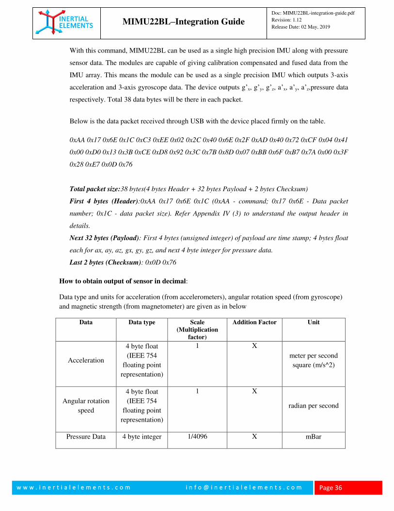
With this command, MIMU22BL can be used as a single high precision IMU along with pressure
sensor data. The modules are capable of giving calibration compensated and fused data from the
IMU array. This means the module can be used as a single precision IMU which outputs 3-axis
acceleration and 3-axis gyroscope data. The device outputs g’x, g’y, g’z, a’x, a’y, a’z,pressure data
respectively. Total 38 data bytes will be there in each packet.
Below is the data packet received through USB with the device placed firmly on the table.
0xAA 0x17 0x6E 0x1C 0xC3 0xEE 0x02 0x2C 0x40 0x6E 0x2F 0xAD 0x40 0x72 0xCF 0x04 0x41
0x00 0xD0 0x13 0x3B 0xCE 0xD8 0x92 0x3C 0x7B 0x8D 0x07 0xBB 0x6F 0xB7 0x7A 0x00 0x3F
0x28 0xE7 0x0D 0x76
Total packet size:38 bytes(4 bytes Header + 32 bytes Payload + 2 bytes Checksum)
First 4 bytes (Header):0xAA 0x17 0x6E 0x1C (0xAA - command; 0x17 0x6E - Data packet
number; 0x1C - data packet size). Refer Appendix IV (3) to understand the output header in
details.
Next 32 bytes (Payload): First 4 bytes (unsigned integer) of payload are time stamp; 4 bytes float
each for ax, ay, az, gx, gy, gz, and next 4 byte integer for pressure data.
Last 2 bytes (Checksum): 0x0D 0x76
How to obtain output of sensor in decimal:
Data type and units for acceleration (from accelerometers), angular rotation speed (from gyroscope)
and magnetic strength (from magnetometer) are given as in below
Data Data type Scale
(Multiplication
factor)
Addition Factor Unit
Acceleration
4 byte float
(IEEE 754
floating point
representation)
1 X
meter per second
square (m/s^2)
Angular rotation
speed
4 byte float
(IEEE 754
floating point
representation)
1 X
radian per second
Pressure Data 4 byte integer 1/4096 X mBar
MIMU22BL–Integration Guide
Doc: MIMU22BL-integration-guide.pdf
Revision: 1.12
Release Date: 02 May, 2019
w w w . i n e r t i a l e l e m e n t s . c o m i n f o @ i n e r t i a l e l e m e n t s . c o m
Page 37
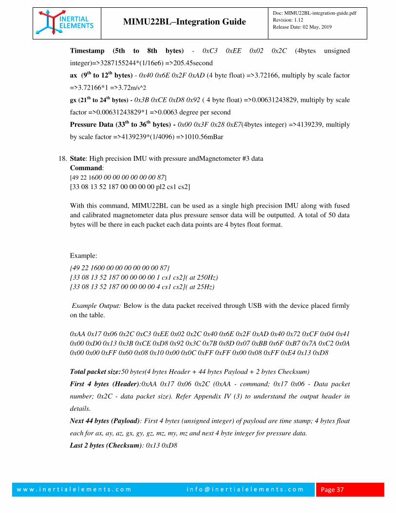
Timestamp (5th to 8th bytes) - 0xC3 0xEE 0x02 0x2C (4bytes unsigned
integer)=>3287155244*(1/16e6) =>205.45second
ax (9th
to 12th
bytes) - 0x40 0x6E 0x2F 0xAD (4 byte float) =>3.72166, multiply by scale factor
=>3.72166*1 =>3.72m/s^2
gx (21th
to 24th
bytes) - 0x3B 0xCE 0xD8 0x92 ( 4 byte float) =>0.00631243829, multiply by scale
factor =>0.00631243829*1 =>0.0063 degree per second
Pressure Data (33th
to 36th
bytes) - 0x00 0x3F 0x28 0xE7(4bytes integer) =>4139239, multiply
by scale factor =>4139239*(1/4096) =>1010.56mBar
18. State: High precision IMU with pressure andMagnetometer #3 data
Command:
[49 22 1600 00 00 00 00 00 00 87]
[33 08 13 52 187 00 00 00 00 pl2 cs1 cs2]
With this command, MIMU22BL can be used as a single high precision IMU along with fused
and calibrated magnetometer data plus pressure sensor data will be outputted. A total of 50 data
bytes will be there in each packet each data points are 4 bytes float format.
Example:
[49 22 1600 00 00 00 00 00 00 87]
[33 08 13 52 187 00 00 00 00 1 cs1 cs2]( at 250Hz)
[33 08 13 52 187 00 00 00 00 4 cs1 cs2]( at 25Hz)
Example Output: Below is the data packet received through USB with the device placed firmly
on the table.
0xAA 0x17 0x06 0x2C 0xC3 0xEE 0x02 0x2C 0x40 0x6E 0x2F 0xAD 0x40 0x72 0xCF 0x04 0x41
0x00 0xD0 0x13 0x3B 0xCE 0xD8 0x92 0x3C 0x7B 0x8D 0x07 0xBB 0x6F 0xB7 0x7A 0xC2 0x0A
0x00 0x00 0xFF 0x60 0x08 0x10 0x00 0x0C 0xFF 0xFF 0x00 0x08 0xFF 0xE4 0x13 0xD8
Total packet size:50 bytes(4 bytes Header + 44 bytes Payload + 2 bytes Checksum)
First 4 bytes (Header):0xAA 0x17 0x06 0x2C (0xAA - command; 0x17 0x06 - Data packet
number; 0x2C - data packet size). Refer Appendix IV (3) to understand the output header in
details.
Next 44 bytes (Payload): First 4 bytes (unsigned integer) of payload are time stamp; 4 bytes float
each for ax, ay, az, gx, gy, gz, mz, my, mz and next 4 byte integer for pressure data.
Last 2 bytes (Checksum): 0x13 0xD8
MIMU22BL–Integration Guide
Doc: MIMU22BL-integration-guide.pdf
Revision: 1.12
Release Date: 02 May, 2019
w w w . i n e r t i a l e l e m e n t s . c o m i n f o @ i n e r t i a l e l e m e n t s . c o m
Page 38
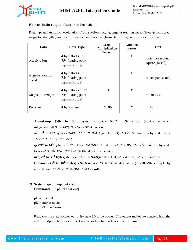
How to obtain output of sensor in decimal:
Data type and units for acceleration (from accelerometers), angular rotation speed (from gyroscope),
magnetic strength (from magnetometer) and Pressure (from Barometer) are given as in below
Data Data Type Scale
(Multiplication
factor)
Addition
Factor Unit
Acceleration
4 byte float (IEEE
754 floating point
representation)
1 X meter per second
square (m/s^2)
Angular rotation
speed
4 byte float (IEEE
754 floating point
representation)
1 X
radian per second
Magnetic strength
4 byte float (IEEE
754 floating point
representation)
0.3 X
micro Tesla
Pressure 4 byte integer 1/4096 X mBar
Timestamp (5th to 8th bytes) - 0xC3 0xEE 0x02 0x2C (4bytes unsigned
integer)=>3287155244*(1/16e6) =>205.45 second
ax (9th
to 12th
bytes) - 0x40 0x6E 0x2F 0xAD (4 byte float) =>3.72166, multiply by scale factor
=>3.72166*1 =>3.72 m/s^2
gx (21th
to 24th
bytes) - 0x3B 0xCE 0xD8 0x92 ( 4 byte float) =>0.00631243829, multiply by scale
factor =>0.00631243829*1 => 0.0063 degree per second
mx(33th
to 36th
bytes) -0xC2 0x0A 0x00 0x00(4 bytes float) => -34.5*0.3 => -10.5 mTesla
Pressure (45th
to 48th
bytes) - 0x00 0x08 0xFF 0xE4 (4bytes integer) =>589796, multiply by
scale factor =>589796*(1/4096) =>143.99 mBar
19. State: Request output of state
Command: [32 pl1 pl2 cs1 cs2]
pl1 = state ID
pl2 = output mode
cs1, cs2: checksum
Requests the state connected to the state ID to be output. The output modebyte controls how the
state is output. The states are ordered according totheir IDs in the response.
MIMU22BL–Integration Guide
Doc: MIMU22BL-integration-guide.pdf
Revision: 1.12
Release Date: 02 May, 2019
w w w . i n e r t i a l e l e m e n t s . c o m i n f o @ i n e r t i a l e l e m e n t s . c o m
Page 39
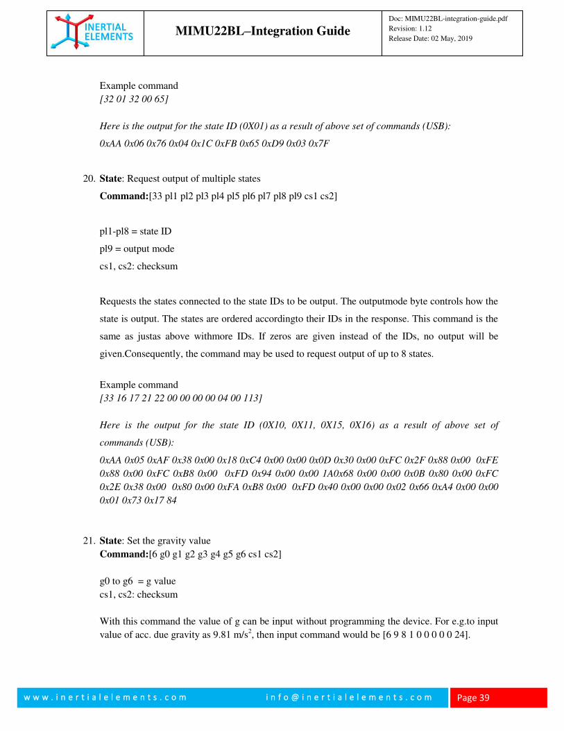
Example command
[32 01 32 00 65]
Here is the output for the state ID (0X01) as a result of above set of commands (USB):
0xAA 0x06 0x76 0x04 0x1C 0xFB 0x65 0xD9 0x03 0x7F
20. State: Request output of multiple states
Command:[33 pl1 pl2 pl3 pl4 pl5 pl6 pl7 pl8 pl9 cs1 cs2]
pl1-pl8 = state ID
pl9 = output mode
cs1, cs2: checksum
Requests the states connected to the state IDs to be output. The outputmode byte controls how the
state is output. The states are ordered accordingto their IDs in the response. This command is the
same as justas above withmore IDs. If zeros are given instead of the IDs, no output will be
given.Consequently, the command may be used to request output of up to 8 states.
Example command
[33 16 17 21 22 00 00 00 00 04 00 113]
Here is the output for the state ID (0X10, 0X11, 0X15, 0X16) as a result of above set of
commands (USB):
0xAA 0x05 0xAF 0x38 0x00 0x18 0xC4 0x00 0x00 0x0D 0x30 0x00 0xFC 0x2F 0x88 0x00 0xFE
0x88 0x00 0xFC 0xB8 0x00 0xFD 0x94 0x00 0x00 1A0x68 0x00 0x00 0x0B 0x80 0x00 0xFC
0x2E 0x38 0x00 0x80 0x00 0xFA 0xB8 0x00 0xFD 0x40 0x00 0x00 0x02 0x66 0xA4 0x00 0x00
0x01 0x73 0x17 84
21. State: Set the gravity value
Command:[6 g0 g1 g2 g3 g4 g5 g6 cs1 cs2]
g0 to g6 = g value
cs1, cs2: checksum
With this command the value of g can be input without programming the device. For e.g.to input
value of acc. due gravity as 9.81 m/s2, then input command would be [6 9 8 1 0 0 0 0 0 24].
MIMU22BL–Integration Guide
Doc: MIMU22BL-integration-guide.pdf
Revision: 1.12
Release Date: 02 May, 2019
w w w . i n e r t i a l e l e m e n t s . c o m i n f o @ i n e r t i a l e l e m e n t s . c o m
Page 40
22. State: Calibration data value set.
Command: [36 pl1 pl2 pl3 pl4 pl5 pl6 pl7 pl8 pl9 pl10 pl11 pl12 pl13 pl14 pl15 pl16 pl17 pl18
pl19 cs1 cs2]
pl1 = select IMU position
pl2 – pl19 = 4 byte calibration data
cs1, cs2: checksum
With this command the calibration file can be input to MIMU22BL without need to reprogram
the device. pl1 is the IMU# and pl2 to pl19 are the calibration data. pl2 –pl4 are the x-axis
accelerometer calibration components, pl5-pl7 and pl8 – pl10 are y axis and z axis accelerometer
calibration components respectively. Similarly pl11-pl13, pl14-pl16 and pl17-pl19 are the x-axis,
y axis and z axis gyroscope calibration components respectively.
23. State: Input fused Accelerometer Bias
Command:[8 pl1 pl2 pl3 cs1 cs2]
pl1 – pl3 = 4 byte each input data
cs1, cs2: checksum
With this command the fused bias estimation value of the accelerometer can be input without
reprogramming the device. pl1,pl2 and pl3 are the bias estimation of the accelerometer along x, y
and z axis respectively.
24. State: Input Fused Gyroscope Bias
Command:[9 pl1 pl2 pl3 cs1 cs2]
pl1 – pl3 = 4 byte each input data
cs1, cs2: checksum
With this command the fused bias estimation value of the gyroscope can be input without
reprogram. pl1,pl2 and pl3 are the bias estimation of the gyroscope along x, y and z axis
respectively.
25. State: Calibration F & G bias Command: [37 pl1 pl2 pl3 pl4 pl5 pl6 pl7 cs1 cs2] pl1 = select IMU position pl2 – pl7 = 4 byte each data cs1, cs2: checksum;
With this command we can give the individual Bias for each IMU. Pl1 is the IMU selected and
pl2 to pl7 is the bias along x, y and z axis of accelerometer and gyroscope respectively
26. State: Set FG scale
MIMU22BL–Integration Guide
Doc: MIMU22BL-integration-guide.pdf
Revision: 1.12
Release Date: 02 May, 2019
w w w . i n e r t i a l e l e m e n t s . c o m i n f o @ i n e r t i a l e l e m e n t s . c o m
Page 41
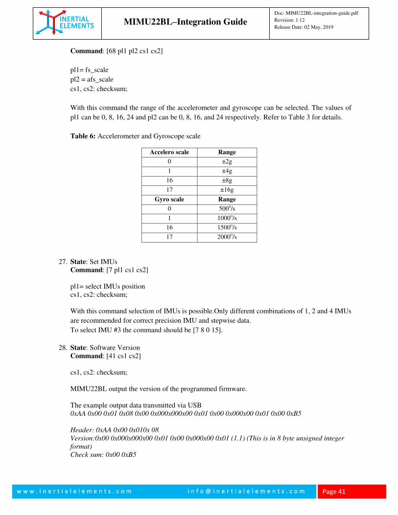
Command: [68 pl1 pl2 cs1 cs2]
pl1= fs_scale
pl2 = afs_scale
cs1, cs2: checksum;
With this command the range of the accelerometer and gyroscope can be selected. The values of
pl1 can be 0, 8, 16, 24 and pl2 can be 0, 8, 16, and 24 respectively. Refer to Table 3 for details.
Table 6: Accelerometer and Gyroscope scale
Accelero scale
Range
0 ±2g 1 ±4g 16 ±8g 17 ±16g Gyro scale Range
0 500o/s
1
1000o/s
16
1500o/s
17 2000o/s
27. State: Set IMUs Command: [7 pl1 cs1 cs2] pl1= select IMUs position cs1, cs2: checksum; With this command selection of IMUs is possible.Only different combinations of 1, 2 and 4 IMUs
are recommended for correct precision IMU and stepwise data.
To select IMU #3 the command should be [7 8 0 15].
28. State: Software Version
Command: [41 cs1 cs2] cs1, cs2: checksum; MIMU22BL output the version of the programmed firmware. The example output data transmitted via USB 0xAA 0x00 0x01 0x08 0x00 0x000x000x00 0x01 0x00 0x000x00 0x01 0x00 0xB5
Header: 0xAA 0x00 0x010x 08
Version:0x00 0x000x000x00 0x01 0x00 0x000x00 0x01 (1.1) (This is in 8 byte unsigned integer
format)
Check sum: 0x00 0xB5
MIMU22BL–Integration Guide
Doc: MIMU22BL-integration-guide.pdf
Revision: 1.12
Release Date: 02 May, 2019
w w w . i n e r t i a l e l e m e n t s . c o m i n f o @ i n e r t i a l e l e m e n t s . c o m
Page 42
29. State: Get Device Id Command: [25 cs1 cs2] cs1, cs2: checksum; MIMU22BL gives the device ID with this command. The example output of the command is given below 0xAA 0x00 0x02 0x08 0x00 0x00 0x16 0x08 0x03 0x00 0x00 0x06 0x00 0xDB
Header:0xAA 0x00 0x02 0x08
ID:0x00 0x00 0x16 0x08 0x03 0x00 0x00 0x06 (This is in 8 byte unsigned integer format)
Check Sum:0x00 0xDB
Note: For all the commands from Sl No. 21 to 27 resetting MIMU22BL will set all the values to
the default programmed values.
30. State: Stepwise Dead Reckoning with true compass heading Command: [67 64 01 31]
MIMU22BL sends out data packet for stepwise dead reckoning along with true compass heading
in response to this command. Use this command only through Bluetooth. It will not work through
USB.Refer Application Note for details.
31. State: Raw IMU and Magnetometer from 4 IMUs
Command1: [48 24 00 72]
Command2: [33 57 58 59 60 185 186 187 188 rd cs1 cs2] MIMU22BL transmitting the inertial sensors’ raw data axi, ayi, azi, gxi, gyi, gzi, magnetometer
raw data mxi, myi, mzi to the application platform.
rd- Output rate divider
cs1 cs2- Check Sum.
Example:
Set of commands to obtain data packets containing 4 accelerometers' and 4 gyroscopes' data, 4
magnetometers,.
Example for USB
[48 24 0 0 72]
[33 57 58 59 60 185 186 187 188 rd cs1 cs2]
MIMU22BL–Integration Guide
Doc: MIMU22BL-integration-guide.pdf
Revision: 1.12
Release Date: 02 May, 2019
w w w . i n e r t i a l e l e m e n t s . c o m i n f o @ i n e r t i a l e l e m e n t s . c o m
Page 43
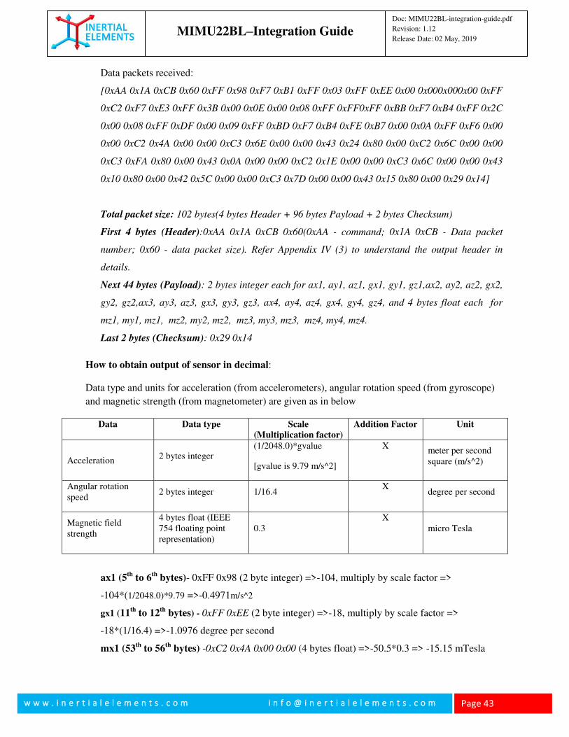
Data packets received:
[0xAA 0x1A 0xCB 0x60 0xFF 0x98 0xF7 0xB1 0xFF 0x03 0xFF 0xEE 0x00 0x000x000x00 0xFF
0xC2 0xF7 0xE3 0xFF 0x3B 0x00 0x0E 0x00 0x08 0xFF 0xFF0xFF 0xBB 0xF7 0xB4 0xFF 0x2C
0x00 0x08 0xFF 0xDF 0x00 0x09 0xFF 0xBD 0xF7 0xB4 0xFE 0xB7 0x00 0x0A 0xFF 0xF6 0x00
0x00 0xC2 0x4A 0x00 0x00 0xC3 0x6E 0x00 0x00 0x43 0x24 0x80 0x00 0xC2 0x6C 0x00 0x00
0xC3 0xFA 0x80 0x00 0x43 0x0A 0x00 0x00 0xC2 0x1E 0x00 0x00 0xC3 0x6C 0x00 0x00 0x43
0x10 0x80 0x00 0x42 0x5C 0x00 0x00 0xC3 0x7D 0x00 0x00 0x43 0x15 0x80 0x00 0x29 0x14]
Total packet size: 102 bytes(4 bytes Header + 96 bytes Payload + 2 bytes Checksum)
First 4 bytes (Header):0xAA 0x1A 0xCB 0x60(0xAA - command; 0x1A 0xCB - Data packet
number; 0x60 - data packet size). Refer Appendix IV (3) to understand the output header in
details.
Next 44 bytes (Payload): 2 bytes integer each for ax1, ay1, az1, gx1, gy1, gz1,ax2, ay2, az2, gx2,
gy2, gz2,ax3, ay3, az3, gx3, gy3, gz3, ax4, ay4, az4, gx4, gy4, gz4, and 4 bytes float each for
mz1, my1, mz1, mz2, my2, mz2, mz3, my3, mz3, mz4, my4, mz4.
Last 2 bytes (Checksum): 0x29 0x14
How to obtain output of sensor in decimal:
Data type and units for acceleration (from accelerometers), angular rotation speed (from gyroscope)
and magnetic strength (from magnetometer) are given as in below
Data Data type Scale
(Multiplication factor)
Addition Factor Unit
Acceleration 2 bytes integer
(1/2048.0)*gvalue
[gvalue is 9.79 m/s^2]
X meter per second square (m/s^2)
Angular rotation speed
2 bytes integer 1/16.4 X
degree per second
Magnetic field strength
4 bytes float (IEEE 754 floating point representation)
0.3 X
micro Tesla
ax1 (5th
to 6th
bytes)- 0xFF 0x98 (2 byte integer) =>-104, multiply by scale factor =>
-104*(1/2048.0)*9.79 =>-0.4971m/s^2
gx1 (11th
to 12th
bytes) - 0xFF 0xEE (2 byte integer) =>-18, multiply by scale factor =>
-18*(1/16.4) =>-1.0976 degree per second
mx1 (53th
to 56th
bytes) -0xC2 0x4A 0x00 0x00 (4 bytes float) =>-50.5*0.3 => -15.15 mTesla
MIMU22BL–Integration Guide
Doc: MIMU22BL-integration-guide.pdf
Revision: 1.12
Release Date: 02 May, 2019
w w w . i n e r t i a l e l e m e n t s . c o m i n f o @ i n e r t i a l e l e m e n t s . c o m
Page 44
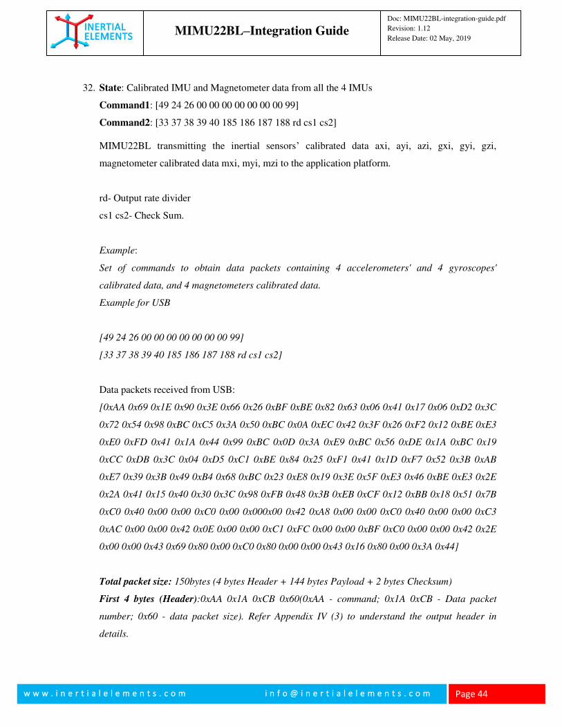
32. State: Calibrated IMU and Magnetometer data from all the 4 IMUs
Command1: [49 24 26 00 00 00 00 00 00 00 99]
Command2: [33 37 38 39 40 185 186 187 188 rd cs1 cs2] MIMU22BL transmitting the inertial sensors’ calibrated data axi, ayi, azi, gxi, gyi, gzi,
magnetometer calibrated data mxi, myi, mzi to the application platform.
rd- Output rate divider
cs1 cs2- Check Sum.
Example:
Set of commands to obtain data packets containing 4 accelerometers' and 4 gyroscopes'
calibrated data, and 4 magnetometers calibrated data.
Example for USB
[49 24 26 00 00 00 00 00 00 00 99]
[33 37 38 39 40 185 186 187 188 rd cs1 cs2]
Data packets received from USB:
[0xAA 0x69 0x1E 0x90 0x3E 0x66 0x26 0xBF 0xBE 0x82 0x63 0x06 0x41 0x17 0x06 0xD2 0x3C
0x72 0x54 0x98 0xBC 0xC5 0x3A 0x50 0xBC 0x0A 0xEC 0x42 0x3F 0x26 0xF2 0x12 0xBE 0xE3
0xE0 0xFD 0x41 0x1A 0x44 0x99 0xBC 0x0D 0x3A 0xE9 0xBC 0x56 0xDE 0x1A 0xBC 0x19
0xCC 0xDB 0x3C 0x04 0xD5 0xC1 0xBE 0x84 0x25 0xF1 0x41 0x1D 0xF7 0x52 0x3B 0xAB
0xE7 0x39 0x3B 0x49 0xB4 0x68 0xBC 0x23 0xE8 0x19 0x3E 0x5F 0xE3 0x46 0xBE 0xE3 0x2E
0x2A 0x41 0x15 0x40 0x30 0x3C 0x98 0xFB 0x48 0x3B 0xEB 0xCF 0x12 0xBB 0x18 0x51 0x7B
0xC0 0x40 0x00 0x00 0xC0 0x00 0x000x00 0x42 0xA8 0x00 0x00 0xC0 0x40 0x00 0x00 0xC3
0xAC 0x00 0x00 0x42 0x0E 0x00 0x00 0xC1 0xFC 0x00 0x00 0xBF 0xC0 0x00 0x00 0x42 0x2E
0x00 0x00 0x43 0x69 0x80 0x00 0xC0 0x80 0x00 0x00 0x43 0x16 0x80 0x00 0x3A 0x44]
Total packet size: 150bytes (4 bytes Header + 144 bytes Payload + 2 bytes Checksum)
First 4 bytes (Header):0xAA 0x1A 0xCB 0x60(0xAA - command; 0x1A 0xCB - Data packet
number; 0x60 - data packet size). Refer Appendix IV (3) to understand the output header in
details.
MIMU22BL–Integration Guide
Doc: MIMU22BL-integration-guide.pdf
Revision: 1.12
Release Date: 02 May, 2019
w w w . i n e r t i a l e l e m e n t s . c o m i n f o @ i n e r t i a l e l e m e n t s . c o m
Page 45
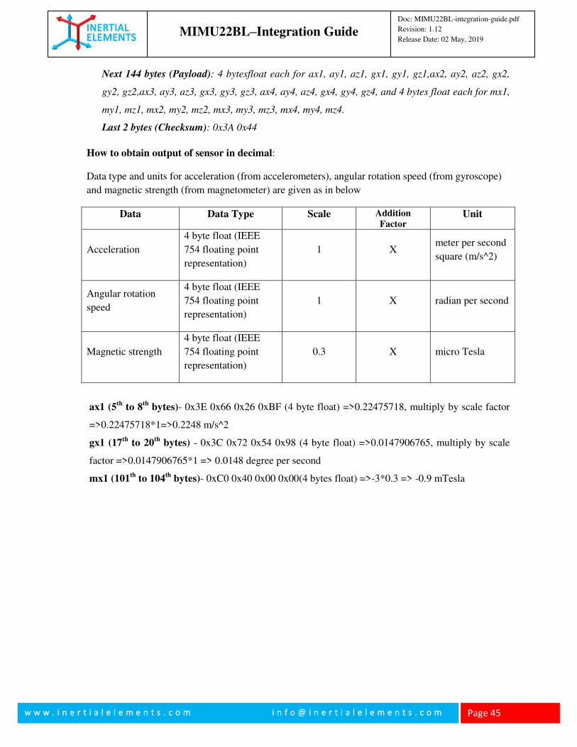
Next 144 bytes (Payload): 4 bytesfloat each for ax1, ay1, az1, gx1, gy1, gz1,ax2, ay2, az2, gx2,
gy2, gz2,ax3, ay3, az3, gx3, gy3, gz3, ax4, ay4, az4, gx4, gy4, gz4, and 4 bytes float each for mx1,
my1, mz1, mx2, my2, mz2, mx3, my3, mz3, mx4, my4, mz4.
Last 2 bytes (Checksum): 0x3A 0x44
How to obtain output of sensor in decimal:
Data type and units for acceleration (from accelerometers), angular rotation speed (from gyroscope)
and magnetic strength (from magnetometer) are given as in below
Data Data Type Scale Addition
Factor Unit
Acceleration
4 byte float (IEEE
754 floating point
representation)
1 X meter per second
square (m/s^2)
Angular rotation
speed
4 byte float (IEEE
754 floating point
representation)
1 X radian per second
Magnetic strength
4 byte float (IEEE
754 floating point
representation)
0.3 X micro Tesla
ax1 (5th
to 8th
bytes)- 0x3E 0x66 0x26 0xBF (4 byte float) =>0.22475718, multiply by scale factor
=>0.22475718*1=>0.2248 m/s^2
gx1 (17th
to 20th
bytes) - 0x3C 0x72 0x54 0x98 (4 byte float) =>0.0147906765, multiply by scale
factor =>0.0147906765*1 => 0.0148 degree per second
mx1 (101th
to 104th
bytes)- 0xC0 0x40 0x00 0x00(4 bytes float) =>-3*0.3 => -0.9 mTesla
MIMU22BL–Integration Guide
Doc: MIMU22BL-integration-guide.pdf
Revision: 1.12
Release Date: 02 May, 2019
w w w . i n e r t i a l e l e m e n t s . c o m i n f o @ i n e r t i a l e l e m e n t s . c o m
Page 46
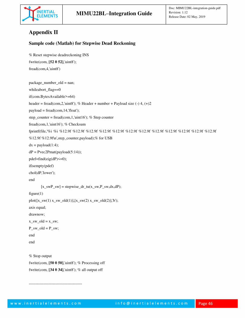
Appendix II
Sample code (Matlab) for Stepwise Dead Reckoning
% Reset stepwise deadreckoning INS
fwrite(com, [52 0 52],'uint8');
fread(com,4,'uint8')
package_number_old = nan;
whileabort_flag==0
if(com.BytesAvailable>=64)
header = fread(com,2,'uint8'); % Header + number + Payload size (-) 4, (+)2
payload = fread(com,14,'float');
step_counter = fread(com,1,'uint16'); % Step counter
fread(com,1,'uint16'); % Checksum
fprintf(file,'%i %i %12.9f %12.9f %12.9f %12.9f %12.9f %12.9f %12.9f %12.9f %12.9f %12.9f %12.9f %12.9f
%12.9f %12.9f\n',step_counter,payload);% for USB
dx = payload(1:4);
dP = Pvec2Pmat(payload(5:14));
pdef=find(eig(dP)<=0);
ifisempty(pdef)
chol(dP,'lower');
end
[x_swP_sw] = stepwise_dr_tu(x_sw,P_sw,dx,dP);
figure(1)
plot([x_sw(1) x_sw_old(1)],[x_sw(2) x_sw_old(2)],'b');
axis equal;
drawnow;
x_sw_old = x_sw;
P_sw_old = P_sw;
end
end
% Stop output
fwrite(com, [50 0 50],'uint8'); % Processing off
fwrite(com, [34 0 34],'uint8'); % all output off
----------------------------------------
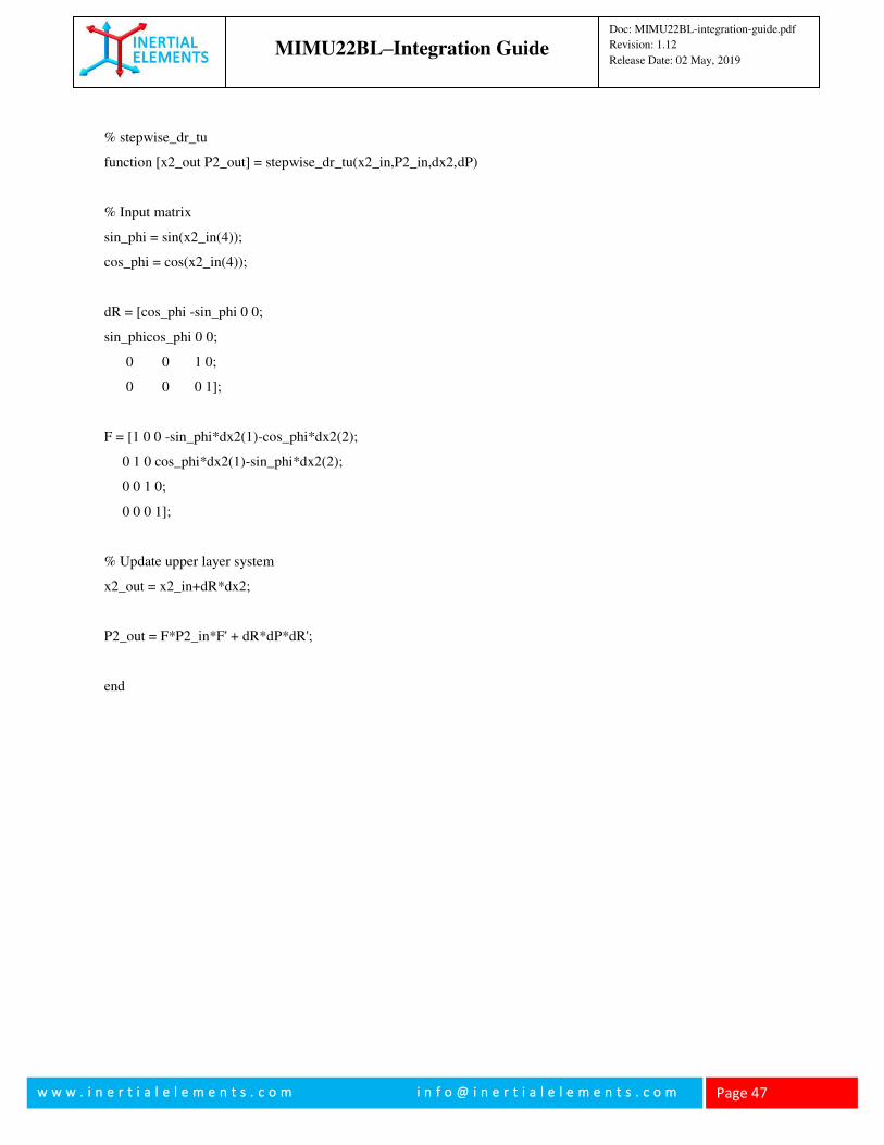
MIMU22BL–Integration Guide
Doc: MIMU22BL-integration-guide.pdf
Revision: 1.12
Release Date: 02 May, 2019
w w w . i n e r t i a l e l e m e n t s . c o m i n f o @ i n e r t i a l e l e m e n t s . c o m
Page 47
% stepwise_dr_tu
function [x2_out P2_out] = stepwise_dr_tu(x2_in,P2_in,dx2,dP)
% Input matrix
sin_phi = sin(x2_in(4));
cos_phi = cos(x2_in(4));
dR = [cos_phi -sin_phi 0 0;
sin_phicos_phi 0 0;
0 0 1 0;
0 0 0 1];
F = [1 0 0 -sin_phi*dx2(1)-cos_phi*dx2(2);
0 1 0 cos_phi*dx2(1)-sin_phi*dx2(2);
0 0 1 0;
0 0 0 1];
% Update upper layer system
x2_out = x2_in+dR*dx2;
P2_out = F*P2_in*F' + dR*dP*dR';
end
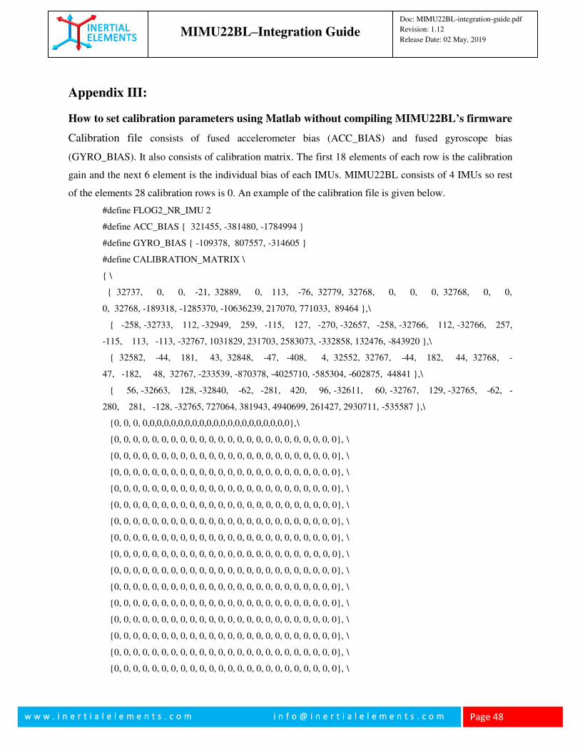
MIMU22BL–Integration Guide
Doc: MIMU22BL-integration-guide.pdf
Revision: 1.12
Release Date: 02 May, 2019
w w w . i n e r t i a l e l e m e n t s . c o m i n f o @ i n e r t i a l e l e m e n t s . c o m
Page 48
Appendix III:
How to set calibration parameters using Matlab without compiling MIMU22BL’s firmware
Calibration file consists of fused accelerometer bias (ACC_BIAS) and fused gyroscope bias
(GYRO_BIAS). It also consists of calibration matrix. The first 18 elements of each row is the calibration
gain and the next 6 element is the individual bias of each IMUs. MIMU22BL consists of 4 IMUs so rest
of the elements 28 calibration rows is 0. An example of the calibration file is given below.
#define FLOG2_NR_IMU 2
#define ACC_BIAS { 321455, -381480, -1784994 }
#define GYRO_BIAS { -109378, 807557, -314605 }
#define CALIBRATION_MATRIX \
{ \
{ 32737, 0, 0, -21, 32889, 0, 113, -76, 32779, 32768, 0, 0, 0, 32768, 0, 0,
0, 32768, -189318, -1285370, -10636239, 217070, 771033, 89464 },\
{ -258, -32733, 112, -32949, 259, -115, 127, -270, -32657, -258, -32766, 112, -32766, 257,
-115, 113, -113, -32767, 1031829, 231703, 2583073, -332858, 132476, -843920 },\
{ 32582, -44, 181, 43, 32848, -47, -408, 4, 32552, 32767, -44, 182, 44, 32768, -
47, -182, 48, 32767, -233539, -870378, -4025710, -585304, -602875, 44841 },\
{ 56, -32663, 128, -32840, -62, -281, 420, 96, -32611, 60, -32767, 129, -32765, -62, -
280, 281, -128, -32765, 727064, 381943, 4940699, 261427, 2930711, -535587 },\
{0, 0, 0, 0,0,0,0,0,0,0,0,0,0,0,0,0,0,0,0,0,0,0,0,0},\
{0, 0, 0, 0, 0, 0, 0, 0, 0, 0, 0, 0, 0, 0, 0, 0, 0, 0, 0, 0, 0, 0, 0, 0}, \
{0, 0, 0, 0, 0, 0, 0, 0, 0, 0, 0, 0, 0, 0, 0, 0, 0, 0, 0, 0, 0, 0, 0, 0}, \
{0, 0, 0, 0, 0, 0, 0, 0, 0, 0, 0, 0, 0, 0, 0, 0, 0, 0, 0, 0, 0, 0, 0, 0}, \
{0, 0, 0, 0, 0, 0, 0, 0, 0, 0, 0, 0, 0, 0, 0, 0, 0, 0, 0, 0, 0, 0, 0, 0}, \
{0, 0, 0, 0, 0, 0, 0, 0, 0, 0, 0, 0, 0, 0, 0, 0, 0, 0, 0, 0, 0, 0, 0, 0}, \
{0, 0, 0, 0, 0, 0, 0, 0, 0, 0, 0, 0, 0, 0, 0, 0, 0, 0, 0, 0, 0, 0, 0, 0}, \
{0, 0, 0, 0, 0, 0, 0, 0, 0, 0, 0, 0, 0, 0, 0, 0, 0, 0, 0, 0, 0, 0, 0, 0}, \
{0, 0, 0, 0, 0, 0, 0, 0, 0, 0, 0, 0, 0, 0, 0, 0, 0, 0, 0, 0, 0, 0, 0, 0}, \
{0, 0, 0, 0, 0, 0, 0, 0, 0, 0, 0, 0, 0, 0, 0, 0, 0, 0, 0, 0, 0, 0, 0, 0}, \
{0, 0, 0, 0, 0, 0, 0, 0, 0, 0, 0, 0, 0, 0, 0, 0, 0, 0, 0, 0, 0, 0, 0, 0}, \
{0, 0, 0, 0, 0, 0, 0, 0, 0, 0, 0, 0, 0, 0, 0, 0, 0, 0, 0, 0, 0, 0, 0, 0}, \
{0, 0, 0, 0, 0, 0, 0, 0, 0, 0, 0, 0, 0, 0, 0, 0, 0, 0, 0, 0, 0, 0, 0, 0}, \
{0, 0, 0, 0, 0, 0, 0, 0, 0, 0, 0, 0, 0, 0, 0, 0, 0, 0, 0, 0, 0, 0, 0, 0}, \
{0, 0, 0, 0, 0, 0, 0, 0, 0, 0, 0, 0, 0, 0, 0, 0, 0, 0, 0, 0, 0, 0, 0, 0}, \
{0, 0, 0, 0, 0, 0, 0, 0, 0, 0, 0, 0, 0, 0, 0, 0, 0, 0, 0, 0, 0, 0, 0, 0}, \
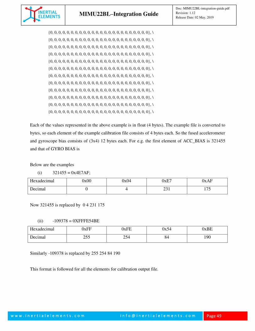
MIMU22BL–Integration Guide
Doc: MIMU22BL-integration-guide.pdf
Revision: 1.12
Release Date: 02 May, 2019
w w w . i n e r t i a l e l e m e n t s . c o m i n f o @ i n e r t i a l e l e m e n t s . c o m
Page 49
{0, 0, 0, 0, 0, 0, 0, 0, 0, 0, 0, 0, 0, 0, 0, 0, 0, 0, 0, 0, 0, 0, 0, 0}, \
{0, 0, 0, 0, 0, 0, 0, 0, 0, 0, 0, 0, 0, 0, 0, 0, 0, 0, 0, 0, 0, 0, 0, 0}, \
{0, 0, 0, 0, 0, 0, 0, 0, 0, 0, 0, 0, 0, 0, 0, 0, 0, 0, 0, 0, 0, 0, 0, 0}, \
{0, 0, 0, 0, 0, 0, 0, 0, 0, 0, 0, 0, 0, 0, 0, 0, 0, 0, 0, 0, 0, 0, 0, 0}, \
{0, 0, 0, 0, 0, 0, 0, 0, 0, 0, 0, 0, 0, 0, 0, 0, 0, 0, 0, 0, 0, 0, 0, 0}, \
{0, 0, 0, 0, 0, 0, 0, 0, 0, 0, 0, 0, 0, 0, 0, 0, 0, 0, 0, 0, 0, 0, 0, 0}, \
{0, 0, 0, 0, 0, 0, 0, 0, 0, 0, 0, 0, 0, 0, 0, 0, 0, 0, 0, 0, 0, 0, 0, 0}, \
{0, 0, 0, 0, 0, 0, 0, 0, 0, 0, 0, 0, 0, 0, 0, 0, 0, 0, 0, 0, 0, 0, 0, 0}, \
{0, 0, 0, 0, 0, 0, 0, 0, 0, 0, 0, 0, 0, 0, 0, 0, 0, 0, 0, 0, 0, 0, 0, 0}, \
{0, 0, 0, 0, 0, 0, 0, 0, 0, 0, 0, 0, 0, 0, 0, 0, 0, 0, 0, 0, 0, 0, 0, 0}, \
{0, 0, 0, 0, 0, 0, 0, 0, 0, 0, 0, 0, 0, 0, 0, 0, 0, 0, 0, 0, 0, 0, 0, 0}, \
{0, 0, 0, 0, 0, 0, 0, 0, 0, 0, 0, 0, 0, 0, 0, 0, 0, 0, 0, 0, 0, 0, 0, 0}, \
Each of the values represented in the above example is in float (4 bytes). The example file is converted to
bytes, so each element of the example calibration file consists of 4 bytes each. So the fused accelerometer
and gyroscope bias consists of (3x4) 12 bytes each. For e.g. the first element of ACC_BIAS is 321455
and that of GYRO BIAS is
Below are the examples
(i) 321455 = 0x4E7AF;
Hexadecimal 0x00 0x04 0xE7 0xAF
Decimal 0 4 231 175
Now 321455 is replaced by 0 4 231 175
(ii) -109378 = 0XFFFE54BE
Hexadecimal 0xFF 0xFE 0x54 0xBE
Decimal 255 254 84 190
Similarly -109378 is replaced by 255 254 84 190
This format is followed for all the elements for calibration output file.
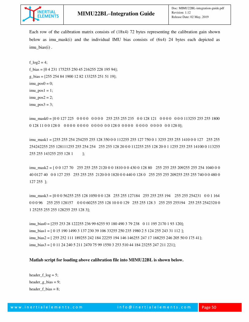
MIMU22BL–Integration Guide
Doc: MIMU22BL-integration-guide.pdf
Revision: 1.12
Release Date: 02 May, 2019
w w w . i n e r t i a l e l e m e n t s . c o m i n f o @ i n e r t i a l e l e m e n t s . c o m
Page 50
Each row of the calibration matrix consists of (18x4) 72 bytes representing the calibration gain shown
below as imu_mask(i) and the individual IMU bias consists of (6x4) 24 bytes each depicted as
imu_bias(i) .
f_log2 = 4;
f_bias = [0 4 231 175255 250 45 216255 228 195 94];
g_bias = [255 254 84 1900 12 82 133255 251 51 19];
imu_pos0 = 0;
imu_pos1 = 1;
imu_pos2 = 2;
imu_pos3 = 3;
imu_mask0 = [0 0 127 225 0 0 0 0 0 0 0 0 255 255 255 235 0 0 128 121 0 0 0 0 0 0 0 113255 255 255 1800
0 128 11 0 0 128 0 0 0 0 0 0 0 0 0 0 0 0 0 0 0 128 0 0 0 0 0 0 0 0 0 0 0 0 0 0 0 128 0];
imu_mask1 = [255 255 254 254255 255 128 350 0 0 112255 255 127 750 0 1 3255 255 255 1410 0 0 127 255 255
254242255 255 128111255 255 254 254 255 255 128 20 0 0 112255 255 128 20 0 1 1255 255 255 14100 0 113255
255 255 143255 255 128 1 ];
imu_mask2 = [ 0 0 127 70 255 255 255 2120 0 0 1810 0 0 430 0 128 80 255 255 255 209255 255 254 1040 0 0
40 0127 40 0 0 127 255 255 255 255 2120 0 0 1820 0 0 440 0 128 0 255 255 255 209255 255 255 740 0 0 480 0
127 255 ];
imu_mask3 = [0 0 0 56255 255 128 1050 0 0 128 255 255 127184 255 255 255 194 255 255 254231 0 0 1 164
0 0 0 96 255 255 128157 0 0 0 60255 255 128 10 0 0 129 255 255 128 3 255 255 255194 255 255 2542320 0
1 25255 255 255 128255 255 128 3];
imu_bias0 = [255 253 28 122255 236 99 6255 93 180 490 3 79 238 0 11 195 2170 1 93 120];
imu_bias1 = [ 0 15 190 1490 3 137 230 39 106 33255 250 235 1980 2 5 124 255 243 31 112 ];
imu_bias2 = [ 255 252 111 189255 242 184 22255 194 146 146255 247 17 168255 246 205 50 0 175 41];
imu_bias3 = [ 0 11 24 240 5 211 2470 75 99 1550 3 253 510 44 184 23255 247 211 221];
Matlab script for loading above calibration file into MIMU22BL is shown below.
header_f_log = 5;
header_g_bias = 9;
header_f_bias = 8;
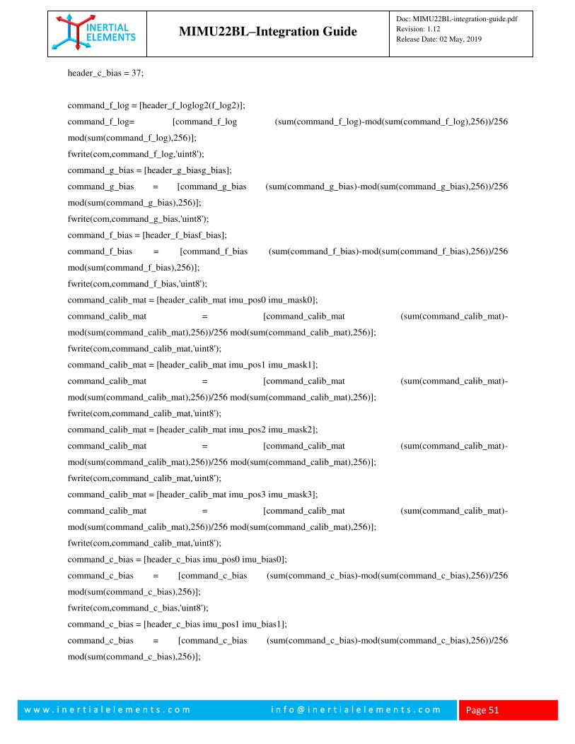
MIMU22BL–Integration Guide
Doc: MIMU22BL-integration-guide.pdf
Revision: 1.12
Release Date: 02 May, 2019
w w w . i n e r t i a l e l e m e n t s . c o m i n f o @ i n e r t i a l e l e m e n t s . c o m
Page 51
header_c_bias = 37;
command_f_log = [header_f_loglog2(f_log2)];
command_f_log= [command_f_log (sum(command_f_log)-mod(sum(command_f_log),256))/256
mod(sum(command_f_log),256)];
fwrite(com,command_f_log,'uint8');
command_g_bias = [header_g_biasg_bias];
command_g_bias = [command_g_bias (sum(command_g_bias)-mod(sum(command_g_bias),256))/256
mod(sum(command_g_bias),256)];
fwrite(com,command_g_bias,'uint8');
command_f_bias = [header_f_biasf_bias];
command_f_bias = [command_f_bias (sum(command_f_bias)-mod(sum(command_f_bias),256))/256
mod(sum(command_f_bias),256)];
fwrite(com,command_f_bias,'uint8');
command_calib_mat = [header_calib_mat imu_pos0 imu_mask0];
command_calib_mat = [command_calib_mat (sum(command_calib_mat)-
mod(sum(command_calib_mat),256))/256 mod(sum(command_calib_mat),256)];
fwrite(com,command_calib_mat,'uint8');
command_calib_mat = [header_calib_mat imu_pos1 imu_mask1];
command_calib_mat = [command_calib_mat (sum(command_calib_mat)-
mod(sum(command_calib_mat),256))/256 mod(sum(command_calib_mat),256)];
fwrite(com,command_calib_mat,'uint8');
command_calib_mat = [header_calib_mat imu_pos2 imu_mask2];
command_calib_mat = [command_calib_mat (sum(command_calib_mat)-
mod(sum(command_calib_mat),256))/256 mod(sum(command_calib_mat),256)];
fwrite(com,command_calib_mat,'uint8');
command_calib_mat = [header_calib_mat imu_pos3 imu_mask3];
command_calib_mat = [command_calib_mat (sum(command_calib_mat)-
mod(sum(command_calib_mat),256))/256 mod(sum(command_calib_mat),256)];
fwrite(com,command_calib_mat,'uint8');
command_c_bias = [header_c_bias imu_pos0 imu_bias0];
command_c_bias = [command_c_bias (sum(command_c_bias)-mod(sum(command_c_bias),256))/256
mod(sum(command_c_bias),256)];
fwrite(com,command_c_bias,'uint8');
command_c_bias = [header_c_bias imu_pos1 imu_bias1];
command_c_bias = [command_c_bias (sum(command_c_bias)-mod(sum(command_c_bias),256))/256
mod(sum(command_c_bias),256)];
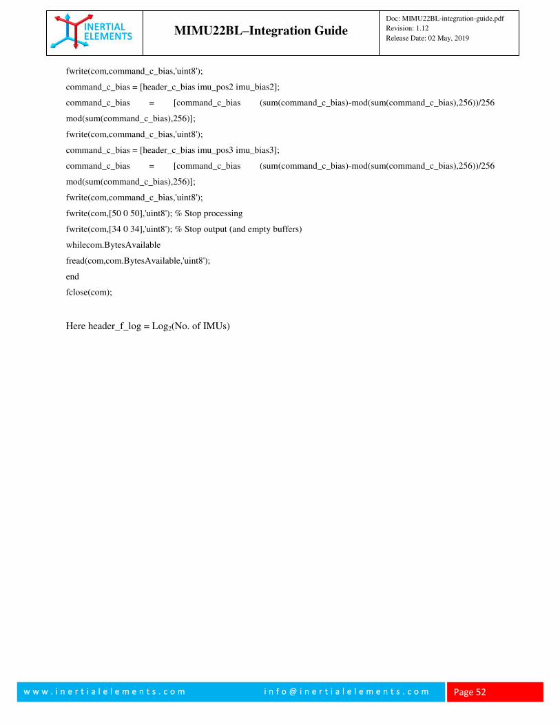
MIMU22BL–Integration Guide
Doc: MIMU22BL-integration-guide.pdf
Revision: 1.12
Release Date: 02 May, 2019
w w w . i n e r t i a l e l e m e n t s . c o m i n f o @ i n e r t i a l e l e m e n t s . c o m
Page 52
fwrite(com,command_c_bias,'uint8');
command_c_bias = [header_c_bias imu_pos2 imu_bias2];
command_c_bias = [command_c_bias (sum(command_c_bias)-mod(sum(command_c_bias),256))/256
mod(sum(command_c_bias),256)];
fwrite(com,command_c_bias,'uint8');
command_c_bias = [header_c_bias imu_pos3 imu_bias3];
command_c_bias = [command_c_bias (sum(command_c_bias)-mod(sum(command_c_bias),256))/256
mod(sum(command_c_bias),256)];
fwrite(com,command_c_bias,'uint8');
fwrite(com,[50 0 50],'uint8'); % Stop processing
fwrite(com,[34 0 34],'uint8'); % Stop output (and empty buffers)
whilecom.BytesAvailable
fread(com,com.BytesAvailable,'uint8');
end
fclose(com);
Here header_f_log = Log2(No. of IMUs)
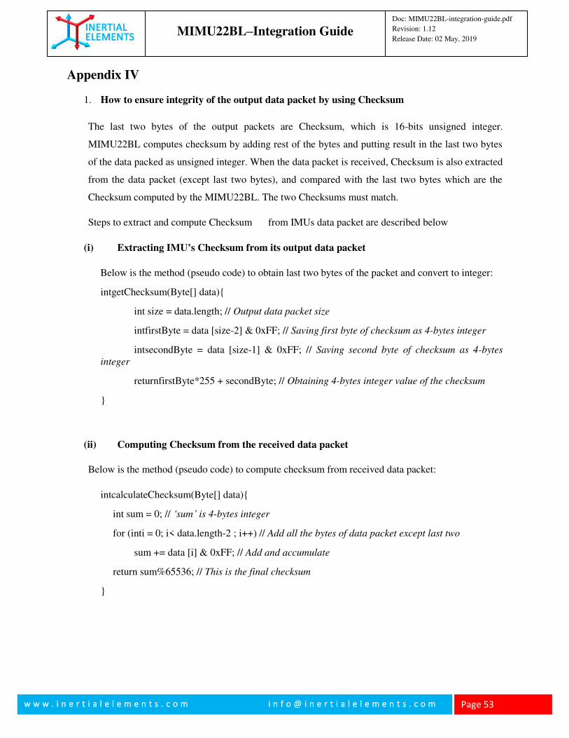
MIMU22BL–Integration Guide
Doc: MIMU22BL-integration-guide.pdf
Revision: 1.12
Release Date: 02 May, 2019
w w w . i n e r t i a l e l e m e n t s . c o m i n f o @ i n e r t i a l e l e m e n t s . c o m
Page 53
Appendix IV
1. How to ensure integrity of the output data packet by using Checksum
The last two bytes of the output packets are Checksum, which is 16-bits unsigned integer.
MIMU22BL computes checksum by adding rest of the bytes and putting result in the last two bytes
of the data packed as unsigned integer. When the data packet is received, Checksum is also extracted
from the data packet (except last two bytes), and compared with the last two bytes which are the
Checksum computed by the MIMU22BL. The two Checksums must match.
Steps to extract and compute Checksum from IMUs data packet are described below
(i) Extracting IMU’s Checksum from its output data packet
Below is the method (pseudo code) to obtain last two bytes of the packet and convert to integer:
intgetChecksum(Byte[] data){
int size = data.length; // Output data packet size
intfirstByte = data [size-2] & 0xFF; // Saving first byte of checksum as 4-bytes integer
intsecondByte = data [size-1] & 0xFF; // Saving second byte of checksum as 4-bytes
integer
returnfirstByte*255 + secondByte; // Obtaining 4-bytes integer value of the checksum
}
(ii) Computing Checksum from the received data packet
Below is the method (pseudo code) to compute checksum from received data packet:
intcalculateChecksum(Byte[] data){
int sum = 0; // ‘sum’ is 4-bytes integer
for (inti = 0; i< data.length-2 ; i++) // Add all the bytes of data packet except last two
sum += data [i] & 0xFF; // Add and accumulate
return sum%65536; // This is the final checksum
}
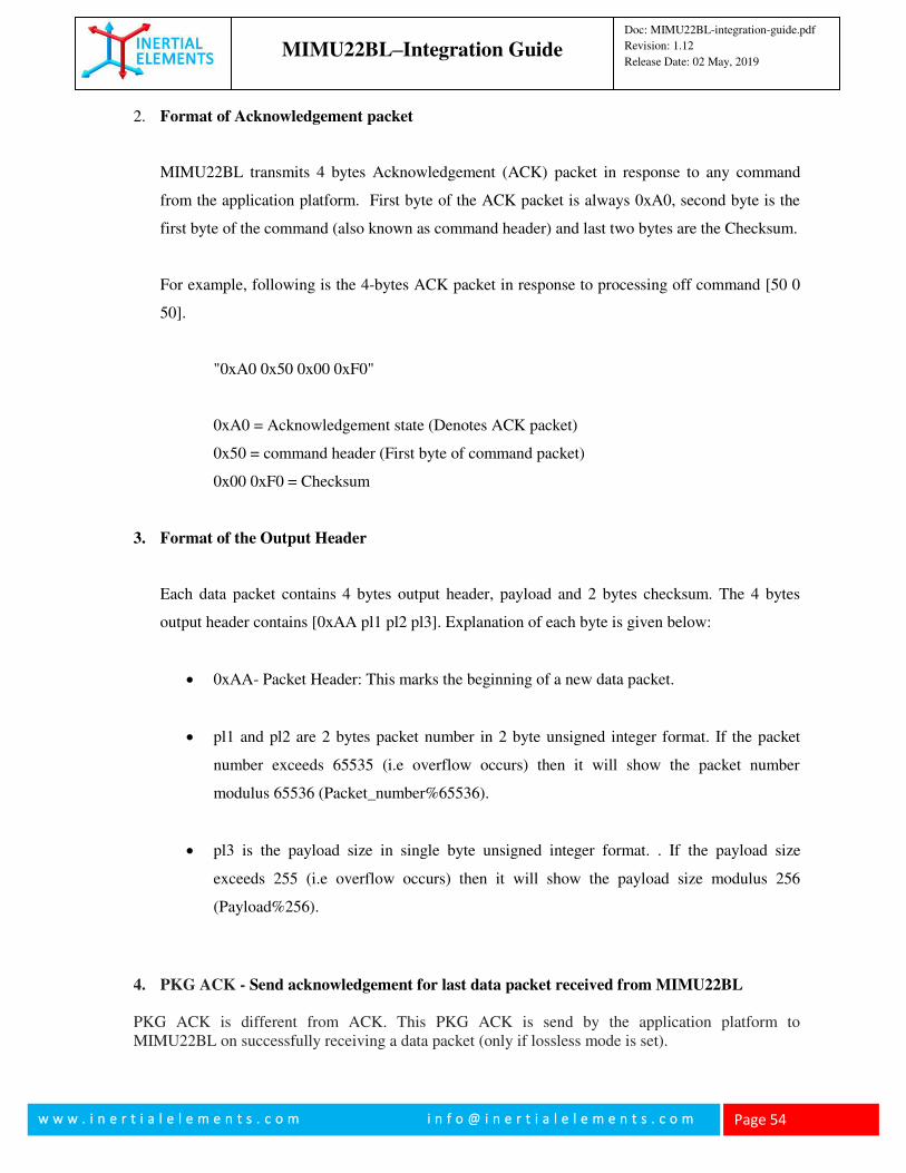
MIMU22BL–Integration Guide
Doc: MIMU22BL-integration-guide.pdf
Revision: 1.12
Release Date: 02 May, 2019
w w w . i n e r t i a l e l e m e n t s . c o m i n f o @ i n e r t i a l e l e m e n t s . c o m
Page 54
2. Format of Acknowledgement packet
MIMU22BL transmits 4 bytes Acknowledgement (ACK) packet in response to any command
from the application platform. First byte of the ACK packet is always 0xA0, second byte is the
first byte of the command (also known as command header) and last two bytes are the Checksum.
For example, following is the 4-bytes ACK packet in response to processing off command [50 0
50].
"0xA0 0x50 0x00 0xF0"
0xA0 = Acknowledgement state (Denotes ACK packet)
0x50 = command header (First byte of command packet)
0x00 0xF0 = Checksum
3. Format of the Output Header
Each data packet contains 4 bytes output header, payload and 2 bytes checksum. The 4 bytes
output header contains [0xAA pl1 pl2 pl3]. Explanation of each byte is given below:
0xAA- Packet Header: This marks the beginning of a new data packet.
pl1 and pl2 are 2 bytes packet number in 2 byte unsigned integer format. If the packet
number exceeds 65535 (i.e overflow occurs) then it will show the packet number
modulus 65536 (Packet_number%65536).
pl3 is the payload size in single byte unsigned integer format. . If the payload size
exceeds 255 (i.e overflow occurs) then it will show the payload size modulus 256
(Payload%256).
4. PKG ACK - Send acknowledgement for last data packet received from MIMU22BL
PKG ACK is different from ACK. This PKG ACK is send by the application platform to MIMU22BL on successfully receiving a data packet (only if lossless mode is set).
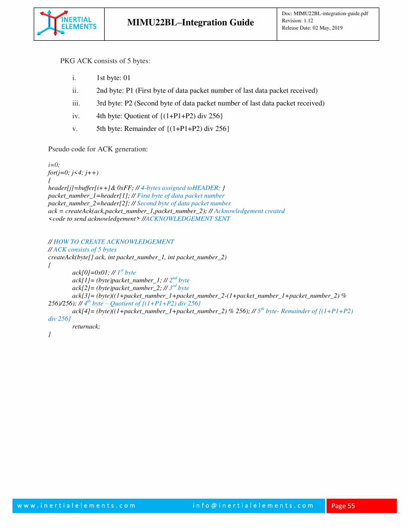
MIMU22BL–Integration Guide
Doc: MIMU22BL-integration-guide.pdf
Revision: 1.12
Release Date: 02 May, 2019
w w w . i n e r t i a l e l e m e n t s . c o m i n f o @ i n e r t i a l e l e m e n t s . c o m
Page 55
PKG ACK consists of 5 bytes:
i. 1st byte: 01
ii. 2nd byte: P1 (First byte of data packet number of last data packet received)
iii. 3rd byte: P2 (Second byte of data packet number of last data packet received)
iv. 4th byte: Quotient of {(1+P1+P2) div 256}
v. 5th byte: Remainder of {(1+P1+P2) div 256}
Pseudo code for ACK generation: i=0;
for(j=0; j<4; j++)
{
header[j]=buffer[i++]& 0xFF; // 4-bytes assigned toHEADER; }
packet_number_1=header[1]; // First byte of data packet number
packet_number_2=header[2]; // Second byte of data packet number
ack = createAck(ack,packet_number_1,packet_number_2); // Acknowledgement created
<code to send acknowledgement> //ACKNOWLEDGEMENT SENT
// HOW TO CREATE ACKNOWLEDGEMENT
// ACK consists of 5 bytes
createAck(byte[] ack, int packet_number_1, int packet_number_2)
{
ack[0]=0x01; // 1st byte
ack[1]= (byte)packet_number_1; // 2nd
byte
ack[2]= (byte)packet_number_2; // 3rd
byte
ack[3]= (byte)((1+packet_number_1+packet_number_2-(1+packet_number_1+packet_number_2) %
256)/256); // 4th
byte – Quotient of {(1+P1+P2) div 256}
ack[4]= (byte)((1+packet_number_1+packet_number_2) % 256); // 5th
byte- Remainder of {(1+P1+P2)
div 256}
returnack;
}
Recommended