MICROWAVE MEASURING INSTRUMENTS
MICROWAVE SYSTEM ANALYZERME453K/L/M, ME538K/L/M70 MHz band 70/140 MHz band
Custom-made productOPTION
The ME453 and ME538 series are used to measure the transmissionline characteristics in the BB and IF bands in terrestrial microwave ra-dio relay systems and in satellite communication systems. The abovetypes of transmission distortion can be measured and analyzed with them.They have been designed with special emphasis on measurement items,performance, functions, precision and size so that they can be used forall types of microwave radio relay systems, such as FDM-FM relay sys-tems, high-efficiency large-capacity digital microwave radio relay sys-tems, and INTELSAT and other satellite communications systems. Uniquespecial innovations contribute greatly to improving handling ease. Toimprove operational ease, a number of internal controls are used andsome measurements are automatic.Furthermore, the measuring parameters and measured values are dis-played digitally, so even when one of these analyzers is used for thefirst time, results can be obtained quickly and accurately.The IF and BB frequencies must coincide for remote testing with othermodels or instruments of other manufacturers. This condition can bemet quite easily by selecting the appropriate model from this particularseries.Multiplexed telephone, TV, PCM and data communications signals aremostly transmitted through microwave radio relay systems. However,when linear distortion (amplitude distortion, phase distortion) or non-lineardistortion (which causes problems, particularly with analog signal trans-mission) is present in the transmission line, distortion noise is generatedin the telephone transmission, clarity and color uniformity are lost withTV transmission and intersymbol interference between codes originat-ing in the waveform distortion results in digital transmission. It is there-fore necessary to measure the distortion in these transmission lines andto equalize it sufficiently.
Measurement items• Group delay characteristics• Linearity and sensitivity in modulators and demodulators• Differential gain characteristics• Differential phase characteristics• IF and BB band amplitude response• IF and BB band return loss• Frequency deviation (or spectrum)• AM/PM conversion coefficient• DC characteristics• IF/BB band power, gam, loss• IF band frequency
ApplicationsThe ME453 and ME538 can be used in the construction, maintenance,or research and development of digital microwave systems and of satellite
376
and terrestrial radio relay systems with BB and IF capability. The meas-urement item relating to the various circuit parts are listed below.• Modulators and demodulators:
Linearity, sensitivity, group delay characteristics, differential gain,differential phase, IF and BB band amplitude characteristics
• Repeater IF sections and overall links:Group delay characteristics, differential gain, differential phase, IF andBB band amplitude characteristics
• Others:IF/BB impedance, power, gain, AM/PM conversion coefficient.The transmitter and receiver are designed to operate independentlyso that end-to-end measurement can be conducted with a singleanalyzer.RF band measurements can be conducted by connecting an up/downconverter to this analyzer.
Functions• LED readout of transmitter settings
For IF and BB measurements, the transmitter settings are shown withunmistakable clarity by the front-panel LED display, so you can readdeviation, sweep width and center frequency at a glance.
• Automatic receiver settings and displayDeviation, IF level, BB frequency and level—all are automatically select-ed and displayed by this receiver. Calibration and attenuation are alsoautomatic.
• Automatic display of unitsBoth sensitivity and units are displayed automatically for all measure-ments, so readings are fast and unmistakably accurate.
• All measurements shown on the CRT and large LED displaysMeasurement parameters and results are displayed on the CRT inalphanumeric form together with the signal trace.They are also displayed simultaneously on the large, easy-to-read LEDdisplay.
• Signal averaging for noisy tracesInternal normalizing circuitry allows you to average traces for remov-ing the noise component—as in the measurement of a satellite sys-tem, for example.
• BB to BB amplitude measurement (optional)An extremely flat baseband sweep generator and detector give youthe end-to-end, BB to BB amplitude response measurements so neces-sary for maintenance of telephone and TV links. The CRT X-axis isa logarithmic frequency scale. Markers are at 60, 100 and 300 kHz,and 1, 3, 10 and 15 MHz.

MICROWAVE MEASURING INSTRUMENTS
• Receiver GP-IB and direct plotting functions (Option)The receiver is computer controllable via the GP-IB which is usablewith either plotters or personal computers. This function enables meas-ured data to be sent to a personal computer for data processing.
Specifications• IF band measurement
The direct plotter function allows CRT displayed data (measured para-meters and displayed signal) to be directly printed out on either a plotteror a dot matrix printer.
ModelsMeasurements
Amplitude(IF INPUT terminal)
Amplitude(RET. LOSS INPUTterminal)
Group delay
Linearity
Differential phase
Differential gain
IF return loss
AM to PMconversion
Spectrum
Deviation
Modulatorsensitivity :
Demodulatorsensitivity
Inherent slopeMeasuring rangeMax. sensitivityIF INPUT levelInherent slopeMeasuring rangeSensitivityINPUT level
Inherent slope
Measuring rangeMax. sensitivityNoiseInherent slopeMeasuring range
Max. sensitivityNoise
Inherent slope
Measuring rangeMax. sensitivityNoise
Inherent slope*
Measuring rangeMax. sensitivityNoiseFrequency rangeMeasuring rangeSensitivityResidual PMMeasuring range
Center frequency
Sweep widthMax. sensitivityDeviationMeasuring rangeAccuracy
Calibration
Mod. signal levelDeviationIF signalDemo. BB level
Inherent noise (IF to IF)
ME453K/L/M70 MHz Band 70 MHz Band
±0.05 dB/±25 MHz ±0.05 dB/±25 MHz0 to 16 dB
ME538K/L/M140 MHz Band
±0.05 dB/±25 MHz, ±0.1 dB/±40 MHz, ±0.2 dB/±50 MHz
0.01 dB/div (Y2 display)+ 10 to -20 dBm±1 dB0 to 40 dB1 dB/div, 5 dB/div-60 to -20 dBm
0.3 ns/±15 MHz, 0.3 ns/±15 MHz,0.5 ns/±25 MHz 0.5 ns/±25 MHz
0 to 400 ns
0.3 ns/±20 MHz, 0.5 ns/±30 MHz,1 ns/±50 MHz
0.1 ns/div(Y2 display)0.05 ns/condition: fM = 200 to 278 kHz, deviation: 200 kHz rms, using average function
0.2°/o/±25 MHz 0.2°/o/±25 MHz 0.2%/±50 MHz0 to 80%0.05%/div0.01%/condition: fM<1 MHz, deviation: 200 kHz rms, using average function
0.3°/±15MHz, 0.3°/±15MHz,0.5°/±25 MHz 0.5°/±25 MHz
0° to 40°
0.3°/±20 MHz, 0.5°/±30 MHz,0.8°/±50MHz
0.2°/div0.02°/condition: fM = 5.6 MHz, deviation: 500 kHz rms, using average function
0.2°/o/±15 MHz, 0.2%/±15 MHz,0.4%/±25 MHz 0.4°/o/±25 MHz
0.3%/±20 MHz, 0.4%/±30 MHz,0.6%/±50 MHz
0 to 80%0.05%/div0.01%/condition: fM = 5.6 MHz, deviation: 500 kHz rms, using average function
70 ± 25 MHz 70 ± 25 MHz10 to 50 dB: Accuracy depends on the bridge
140 ± 50 MHzused
1 dB/div, 5 dB/div0.3°/dB/±25 MHz 0.3°/dB/±25 MHz0.3°/dB to 16°/dB
70±20MHz 70±20MHzAuto tuning Auto tuning
Approx. ±700 kHzDetects 0.1 dB change of modulating signal atK: 340 kHz rms at 200 kHz, L: 472 kHz rms at20 to 999 kHz rms at the built-in
0.3°/dB/±35 MHz
140 ±30 MHzAuto tuning
carrier zero point277.778 kHz, M: 425 kHz rms at 250 kHz
BB frequencies <8.2 MHz10% at the built-in BB frequencies <8.2 MHz
Deviation is calibrated by easy pushbutton operation.Accuracy reaches 1% theoretically at the specified modulation frequency and deviation (as measuredby the Bessel zero method) shown below.
Model MOD frequencyK 200 kHzL 277.778 kHzM 250 kHz
Key in facto340 kHz rms472 kHz rms425 kHz rms
r
-50 to +10 dBmUse the DEVIATION meter function or use the carrier zero deviation with the SPECTRUM functionCalibrate the deviation with DEVIATION meter function or SPECTRUM function-50 to +10 dBm
Group delay
66 to 93 kHz: 0.3 ns rms200 to 278 kHz: 0.1 ns rms400 to 556 kHz: 0.05 ns rms
Linearity
0.02% rms
Deviation: 200 kHz rms, fM<1 MHz
Differential Differentialphase gain
0.05° rms 0.1% rmsDetection band: 3 kHz
Deviation: 500 kHz rms, fM = 5.6 MHz• Specified frequency range = Carrier sweep width +2 f
377
MICROWAVE MEASURING INSTRUMENTS
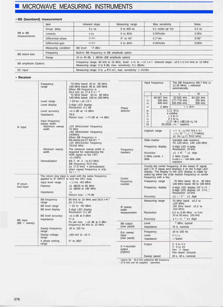
• BB (baseband) measurement
BB to BBmeasurements
BB return loss
Item
Group delay
Linearity
Differential phase
Differential gain
Measuring condition
Frequency
Range
BB amplitude (Option)
DC input
Inherent slope
0.1 ns
0.1%
0.1%
0.1%
Measuring range
0 to 400 ns
0 to 80%
0° to 40°
0 to 80%
Max. sensitivity
0.1 ns/div (at Y2)
0.05%/div
0.2°/div
0.05%/div
Noise
0.2 ns
0.05%
0.05°
0.05%
BB level: -30 dBm
Built-in BB frequency or BB amplitude option
10 to 40 dB, 1 dB/div (BB amplitude option)
Frequency range: 60 kHz to 15 MHz, level: +10 to -50dBm, inherent slope: ±0.5 dB/100 kHz to 13 MHzMeasuring range: 0 to 8 dB, max. sensitivity: 0.1 dB/div
Measuring range: 0 to ±400mV, max. sensitivity: 1 mV/div
• Receiver
IF input
IF returnloss input
BB input(BB + sweep)
Frequencyrange
Level rangeLevel display
Level accuracyImpedance
Input frequencysweep width
Maximum sweepwidth
Minimum sweepwidth
Demodulation
70 MHz band: 45 to 95 MHz140 MHz band: 90 to 190 MHzWhen BB frequency is55.6 kHz (or 27.8 kHz}.*1
70 MHz band: 60 to 80 MHz140 MHz band: 130 to 150 MHz+ 10 to -20dBm3-digit LED displayResolution: 0.1 dB±0.3 dB at +4 dBm75 0Return loss: >30 dB at +4 dBm
±25 MHz/center frequency70 MHz±50 MHz/center frequency140MHzWhen BB frequency is55.6 kHz (or 27.8 kHz)/1
±10 MHz/center frequency70/140 MHzThe minimum sweep width isrequired for reproducing theHOR signal on the CRT,±0.2 MHz66.7, 80 kHz to 8.2 MHzBB frequency 55.6 kHz(or 27.8 kHz) is demodulatedwhen sweep frequency is only18 Hz/1
The return loss input is used with the same frequencyapplied to IF INPUT to lock the AFC loop.Input level rangeFlatness
Impedance
BB frequencyrangeBB level rangeBB level display
BB level accuracyImpedance
Sweep frequencyrangeSweep voltagerangeX phase settingrange
-20 to -60 dBm±1 dB/45 to 95 MHz±1 dB/90 to 190 MHz75ohmReturn loss: >28 dB
66 kHz to 15 MHz and 55.6 kHz*1
(or 27.8 kHz)
+ 10 to -50 dBm3-digit LED displayResolution: 0.1 dB±0.3 dB at 0 dBm
75ohmReturn loss: >28 dB at 0 dBmfrequency 66 kHz to 15 MHz18 to 100 Hz
±50 mV to ±5 V
0° to 360°
Phasedetector
Frequencymarkers
Centerfrequencycounter
IF sweepwidthmeasurement
BB output(rear panel)
Ext. sweepInput(rear panel)
X-Y recorderoutput(Option)
Input
fif2f3
f4
f5f6f7fsf9f10
frequency
K
66.667 kHz200 kHz400 kHz
2 MHz
The BB frequency (66.7 kHz12.39 MHz) is selectedautomatically.
L M92.593 kHz 83.333 kHz
277.778 kHz 250 kHz555.556 kHz 500 kHz
2.4MHz3.58MHz4.43 MHz
5.6MHz8.2MHz
12.39MHz(ME538K/L/M)55.5556 kHz*2 (option)
Capture range
Slide marker
Frequency display
Accuracy2 MHz comb +slide
Counts the center freand CW-IF signal ancdisplay. The display 'select ng either the sfrequency with a keyFrequency range
Frequency display
Accuracy
Measuring range
Resolution
Accuracy
LevelImpedance
FrequencyLevelmpedance
Output
Sweep speed
±5Hz(<555.556kHz)±5x10- 6 (<12.39 MHz)±1 Hz (<55. 5556 kHz)
to
Variable side markers:70 ±25 MHz, 140 ±50 MHz4-digit LED d splayResolution: 10 kHz±1 x 1 0 - 4 ±1 digit2 MHz Combmarkers + Var able sidemarkers
quency of the swept IF signald displays it on the 5-digit LEDo the LED display is made byde marker frequency or center
70 MHz band: 45 to 90 MHz140 MHz band: 90 to 190 MHz4-digit LED display (ME453D)5-digit LED display (ME538D)Resolution: 10 kHz±1 x10~ 3 ±1 digit
70 MHz band: ±0.2 to±25 MHz140 MHz band: ±0.2 to±50 MHz0.2 to 9.99 MHz: 10kHz10 to 50 MHz: 100 kHz±5x10- 2 ±1 digit
-7 dBm, typical75 0, nominal
18 to 100 Hz1 Vp-p
>5 kohm
X: 0 to 4 VY: 0 to 4VPen lift: OpenPen down: Ground20 s, 40 s, nominal
1 Option 05: 55.6 kHz additional BB frequency2 27.8 kHz can be supplied if specified.
378
MICROWAVE MEASURING INSTRUMENTS
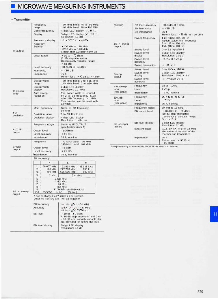
• Transmitter
IF output
IF sweepwidth
FMdeviation
AUX IFoutput
Crystaloutput
BB + sweepoutput
FrequencyrangeCenter frequency
Display
Frequency display
AccuracyStability
Level range
Level accuracyHarmonicsmpedance
Sweep widthrange
Sweep widthdisplay
Auto sweepreduct on
Mod. frequency
Deviation range
Deviation display
Frequency range
Output levelLevel accuracy
Impedance
Frequency
Output level
Level accuracympedance
70 MHz band: 45 to 95 MHz140 MHz band: 90 to 190 MHz
4-digit LED display (ME453D)
5-digit LED display (ME538D)Resolution: 10 kHz
±1 x10- 4 ±1 digit/CW
±100 kHz at 70 MHz±200 kHz at 140 MHz5-hour after 1/2-hour warm-up
+ 10 to -70 dBm(1 dB step attenuator)Continuously variable range:> ±1 dB±0.3 dB at +4 dBm< -30 dB75 fiReturn loss: >30 dB at +4 dBm
70 MHz band: 0 to ±25 MHz140 MHz band: 0 to ±50 MHz
3-digit LED d splayResolution: 0.1 MHz
The sweep width is reducedby 2 x BB frequency ±10%when BB frequency >1 MHz.This function can be reset witha switch.
Same as BB frequency(item 6)
5 to 1000 kHz rms4-digit LED displayResolution: 1 kHz rms
Same as IF OUTPUTspecification (item 1)
-10dBm
< ±1 dB75 fi, nominal
70 MHz band: 70 MHz140 MHz band: 140 MHz
+ 5 dBm< ±1 dB75 fi, nominal
BB frequency
K
f i 66.667 kHzf2 200 kHzf3 400 kHzf4 2 MHz
L M
92.593 kHz 83.333 kHz277.778 kHz 250 kHz555.556 kHz 500 kHz
2.4 MHzf5 3.58 MHzf6 4.43 MHzf7 5.6 MHzf8 8.2 MHzf9 12.39MHz (ME538K/L/M)f10 55.5556 kHz* (Option)
* Can be changed to 27Option 05: 55.6 kHz adc
BB frequency
Accuracy
BB level
BB level display
.778 kHz if so specified.Jtional BB frequency.
±5 Hz (<555. 556 kHz)
± 5 x 1 0 - 6 (<12.39 MHz)±1 Hz (<55.5556 kHz)
+ 10 to -50 dBmA 10 dB step attenuator and 0 to- 10 dB cont nuously variable dialare provided for setting the level.
3-digit LED displayResolution: 0.1 dB
(Contd.)
BB + sweepoutput
Sweepoutput
Ext. sweepinput(rear panel)
Ext. BBinput(rear panel)
BB sweeper(option)
BB level accuracyBB harmonics
BB impedance
Sweep frequency
Sweep level
Sweep leveldisplay
Sweep levelaccuracySweep harmonics
Sweep levelSweep leveldisplaySweep levelaccuracy
FrequencyLevel
Impedance
FrequencyLevelImpedance
Frequency range
BB output level
BB level display
Inherent slope
Impedance
±0.3 dB at 0 dBm< -38 dB75 fiReturn loss: >28 dB at - 10 dBm
Line (50/60 Hz), 70 HzOption (select one frequencyfrom 18 to 100 Hz)Ext. (18 to 100 Hz)0 to 6.5 Vp-p/75 fi
3-digit LED displayResolution: 0.01 V
±10% at 6 Vp-p
<-35dB
0 to 25 Vp-p/10 kfi
3-digit LED displayResolution: 0.01 x 4 V±10% at 24 Vp-p
18 to 100 Hz2 Vp-p10 kfi, nominal
80kHz to 15MHz-7 dBm75 fi, nominal
60 kHz to 15 MHz+ 10 dBm to -50 dBm(10 dB step attenuator)Continuously variable range:0 to - 10dB3-digit LED displayResolution: 0.1 dB±0.5 dB/100 kHz to 13 MHzThe value of the sum of thereceiver and transmitter
75 fiReturn loss: >28 dB at- 10 dBm
Sweep frequency is automatically set to 18 Hz when f, is selected.
379

MICROWAVE MEASURING INSTRUMENTS
• Low BB frequency: 55.6 kHz or 27.8 kHz (Option) • General specifications
Group delay
Linearity
Inherent slope
Measuring range
Max. sensitivity
Noise
Inherent slope
Measuring range
Max. sensitivity
Noise
70 ±10 MHz: 5 ns140 ±10 MHz: 5 ns
0 to 400 ns
2 ns/div
1 ns
70 ±10 MHz: 0.5%140 ±10 MHz: 0.5%
0 to 80%
0.1%/div
0.1%
With deviation 100 kHz rms and sweep frequency 18 Hz using average function
Ordering informationPlease specify model/order number, name and quantity when ordering.
Input and outputconnector
Power
Ambient temperature,rated range of use
Dimensions andmass
BNC or SP connectorOther type of connectors can be installedif requested by the user: e.g., SiemensSmall, Weco 560A or equivalent.
260 VATransmitter: 85 VAReceiver: 1 75 VAFrom AC 100 V to AC 250 V, at therequest of the user.Tolerance ±10%
0° to 50°C
Receiver: 177H x 426W x 450D mm,<18.5 kgTransmitter: 133H x 426W x 450D mm,< 13.5 kg
Model/Order No.
ME453KME453LME453MME538KME538LME538M
J0082A
J0092C
J0134BO0 19B0020F0023F0022F0045W0094CE
MSA-01MSA-02MSA-03MSA-04MSA-05
MR55A1MR43A
MB23AMB24A
Name
Main frame
Microwave System AnalyzerMicrowave System AnalyzerMicrowave System Analyzer ;Microwave System AnalyzerMicrowave System AnalyzerMicrowave System Analyzer
Standard accessoriesCoaxial Cord, 2m: 3 pcs
Coaxial Cord, 2m: 3 pcs
Power Cord, 2.5 m: 2 pcsFront Cover: 1 pcFront Cover: 1 pcFuse, 3.15 A: 2 pcsFuse, 2 A: 2 pcsFuse, 2 A: 4 pcsME453K/L/M, ME538K/L/M Operation and ServiceManual: 1 copy
OptionsBB Amplitude Measurement jX-Y Recorder OutputSweeper Frequency AddedReceiver GP-IB, Direct Plotting of CRT Output55.6 kHz BB Frequency Added
Optional accessoriesIF Return Loss BridgeBB Return Loss Bridge
PeripheralsPortable Test RackPortable Test Rack
Remarks
IF bands BB Std. I/O connector
70 MHz 200kHz SP70 MHz 278 kHz BNC70 MHz 250 kHz BNC70/1 40 MHz 200kHz SP70/1 40 MHz 278kHz BNC70/1 40 MHz 200kHz BNC
SP-3CP.3C-2WS-SP-3CPfor SP connector (Either one isBNC-P620-3C-2W.BNC-P620 attached)for BNC connectorOne each for transmitter and receiverFor transmitterFor receiverMF51NN250V3.15AAC05MF51NN250V2AAC05MF51NN250V2ADC01
Processed at factory
Specify one frequency from 18 to 100 Hz
Change to 27.8 kHz possible, option 03 (18 Hz) isrequired.
Connector: SP or BNCConnector: SP or BNC
Tilt angleHorizontally fixed
380
Recommended