2
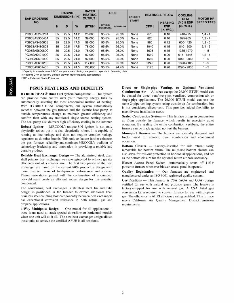
SAP ORDERINGNO.
CASINGDIMENSIONS (IN.)
RATEDHEATINGOUTPUT†
AFUEENERGYSTARR
HEATING AIRFLOW COOLINGCFM
@ 0.5 ESP(in. W.C.)
MOTOR HPSPEED TAPS
H D W (BTUH) UPFLOW/HORIZONTAL
DOWNFLOW CFM‡HEATINGESP
(in. W.C.)PG95SAS24026A 35 29.5 14.2 25,000 95.5% 95.0% None 675 0.10 440-775 1/4 - 4PG95SAS30040A 35 29.5 14.2 39,000 95.5% 95.0% None 820 0.10 625-905 1/2 - 4PG95SAS42060B 35 29.5 17.5 58,000 95.5% 95.0% None 980 0.12 650-1420 1/2 - 5PG95SAS48080B 35 29.5 17.5 78,000 95.5% 95.0% None 1040 0.15 810-1600 3/4 - 5PG95SAS60080C 35 29.5 21.0 78,000 95.5% 95.0% None 1695 0.15 1335-1970 1 - 5PG95SAS42100C 35 29.5 21.0 97,000 95.5% 95.0% None 1510 0.20 915---1545 1/2 - 4PG95SAS60100C 35 29.5 21.0 97,000 95.5% 95.0% None 1680 0.20 1345---2065 1 - 5PG95SAS60120D 35 29.5 24.5 117,000 95.5% 95.0% None 2245 0.20 1320-2105 1 - 5PG95SAS60140D 35 29.5 24.5 135,000 95.5% 94.4% None 2175 0.20 1290---2035 1 - 5
† Capacity in accordance with DOE test procedures. Ratings are position dependent. See rating plate.
‡ Heating CFM at factory default blower motor heating tap settings.ESP --- External Static Pressure
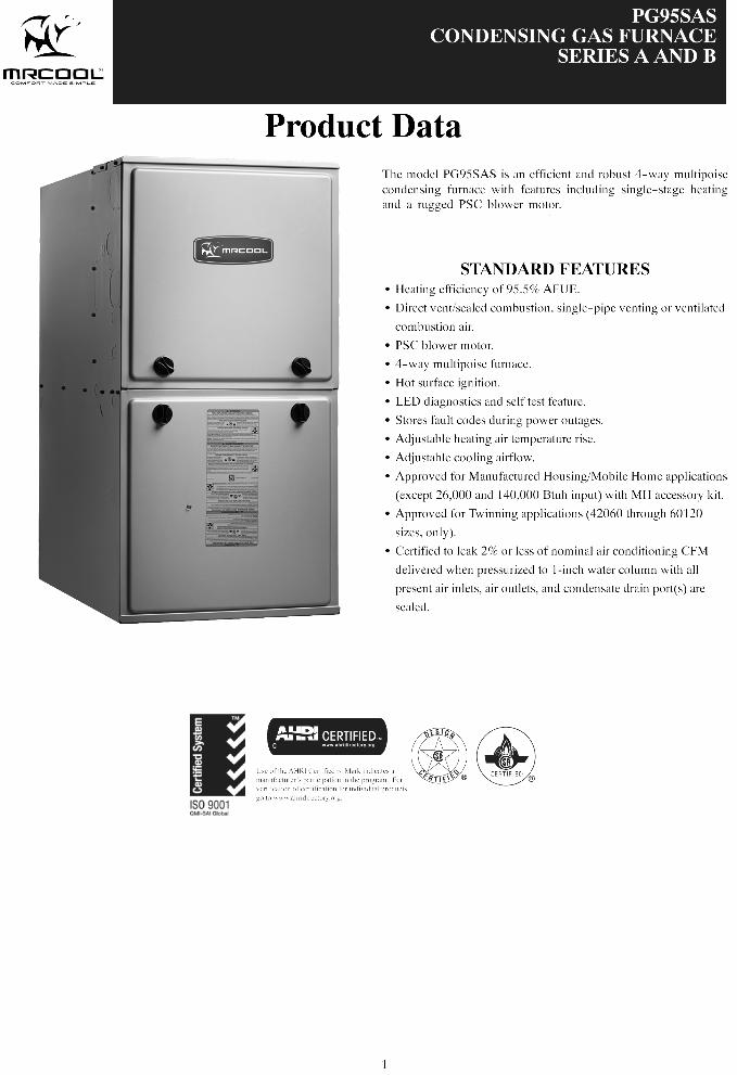
PG95S FEATURES AND BENEFITSHYBRID HEATR Dual Fuel system compatible— This systemcan provide more control over your monthly energy bills byautomatically selecting the most economical method of heating.With HYBRID HEAT components, our system automaticallyswitches between the gas furnace and the electric heat pump asoutside temperatures change to maintain greater efficiency andcomfort than with any traditional single-source heating system.The heat pump also delivers high-efficiency cooling in the summer.
Robust Igniter —MRCOOL’s unique SiN igniter is not onlyphysically robust but it is also electrically robust. It is capable ofrunning at line voltage and does not require complex voltageregulators as do other brands. This unique feature further enhancesthe gas furnace reliability and continues MRCOOL's tradition oftechnology leadership and innovation in providing a reliable anddurable product.
Reliable Heat Exchanger Design — The aluminized steel, clamshell primary heat exchanger was re--engineered to achieve greaterefficiency out of a smaller size. The first two passes of the heatexchanger are based on the current 80% product, a design withmore than ten years of field-proven performance and success.These innovations, paired with the continuation of a crimped,no-weld seam create an efficient, robust design for this essentialcomponent.
The condensing heat exchanger, a stainless steel fin and tubedesign, is positioned in the furnace to extract additional heat.Stainless steel coupling box componentry between heat exchangershas exceptional corrosion resistance in both natural gas andpropane applications.
4-Way Multipoise Design — One model for all applications –there is no need to stock special downflow or horizontal modelswhen one unit will do it all. The new heat exchanger design allowsthese units to achieve the certified AFUE in all positions.
Direct or Single-pipe Venting, or Optional VentilatedCombustion Air— All sizes except the 26,000 BTUH model canbe vented for direct vent/two-pipe, ventilated combustion air, orsingle-pipe applications. The 26,000 BTUH model can use thesame 2--pipe venting system using outside air for combustion, butis not considered direct--vent. This provides added flexibility tomeet diverse installation needs.
Sealed Combustion System— This furnace brings in combustionair from outside the furnace, which results in especially quietoperation. By sealing the entire combustion vestibule, the entirefurnace can be made quieter, not just the burners.
Monoport Burners — The burners are specially designed andfinely tuned for smooth, quiet combustion and economicaloperation.
Bottom Closure — Factory--installed for side return; easilyremovable for bottom return. The multi-use bottom closure canalso serve for roll-out protection in horizontal applications, and actas the bottom closure for the optional return air base accessory.
Blower Access Panel Switch—Automatically shuts off 115-vpower to furnace whenever blower access panel is opened.
Quality Registration — Our furnaces are engineered andmanufactured under an ISO 9001 registered quality system.
Certifications — This furnace is CSA (AGA and CGA) designcertified for use with natural and propane gases. The furnace isfactory--shipped for use with natural gas. A CSA listed gasconversion kit is required to convert furnace for use with propanegas. The efficiency is AHRI efficiency rating certified. This furnacemeets California Air Quality Management District emissionrequirements.
PG95SAS
3
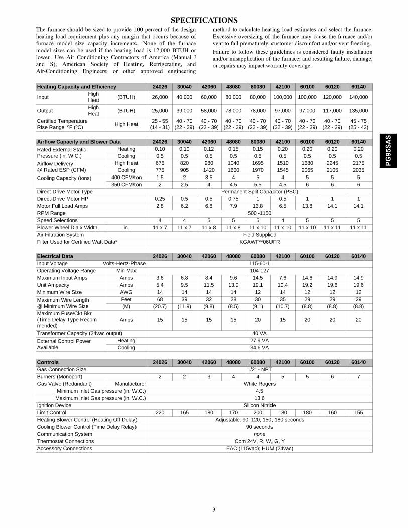
SPECIFICATIONSThe furnace should be sized to provide 100 percent of the designheating load requirement plus any margin that occurs because offurnace model size capacity increments. None of the furnacemodel sizes can be used if the heating load is 12,000 BTUH orlower. Use Air Conditioning Contractors of America (Manual Jand S); American Society of Heating, Refrigerating, andAir-Conditioning Engineers; or other approved engineering
method to calculate heating load estimates and select the furnace.Excessive oversizing of the furnace may cause the furnace and/orvent to fail prematurely, customer discomfort and/or vent freezing.
Failure to follow these guidelines is considered faulty installationand/or misapplication of the furnace; and resulting failure, damage,or repairs may impact warranty coverage.
Heating Capacity and Efficiency 24026 30040 42060 48080 60080 42100 60100 60120 60140
InputHighHeat
(BTUH) 26,000 40,000 60,000 80,000 80,000 100,000 100,000 120,000 140,000
OutputHighHeat
(BTUH) 25,000 39,000 58,000 78,000 78,000 97,000 97,000 117,000 135,000
Certified TemperatureRise Range ºF (ºC)
High Heat25 - 55
(14 - 31)40 - 70
(22 - 39)40 - 70
(22 - 39)40 - 70
(22 - 39)40 - 70
(22 - 39)40 - 70
(22 - 39)40 - 70
(22 - 39)40 - 70
(22 - 39)45 - 75
(25 - 42)
Airflow Capacity and Blower Data 24026 30040 42060 48080 60080 42100 60100 60120 60140
Rated External StaticPressure (in. W.C.)
Heating 0.10 0.10 0.12 0.15 0.15 0.20 0.20 0.20 0.20Cooling 0.5 0.5 0.5 0.5 0.5 0.5 0.5 0.5 0.5
Airflow Delivery@ Rated ESP (CFM)
High Heat 675 820 980 1040 1695 1510 1680 2245 2175Cooling 775 905 1420 1600 1970 1545 2065 2105 2035
Cooling Capacity (tons) 400 CFM/ton 1.5 2 3.5 4 5 4 5 5 5350 CFM/ton 2 2.5 4 4.5 5.5 4.5 6 6 6
Direct-Drive Motor Type Permanent Split Capacitor (PSC)Direct-Drive Motor HP 0.25 0.5 0.5 0.75 1 0.5 1 1 1Motor Full Load Amps 2.8 6.2 6.8 7.9 13.8 6.5 13.8 14.1 14.1RPM Range 500 -1150Speed Selections 4 4 5 5 5 4 5 5 5Blower Wheel Dia x Width in. 11 x 7 11 x 7 11 x 8 11 x 8 11 x 10 11 x 10 11 x 10 11 x 11 11 x 11Air Filtration System Field SuppliedFilter Used for Certified Watt Data* KGAWF**06UFR
Electrical Data 24026 30040 42060 48080 60080 42100 60100 60120 60140Input Voltage Volts-Hertz-Phase 115-60-1Operating Voltage Range Min-Max 104-127Maximum Input Amps Amps 3.6 6.8 8.4 9.6 14.5 7.6 14.6 14.9 14.9Unit Ampacity Amps 5.4 9.5 11.5 13.0 19.1 10.4 19.2 19.6 19.6Minimum Wire Size AWG 14 14 14 14 12 14 12 12 12
Maximum Wire Length@ Minimum Wire Size
Feet 68 39 32 28 30 35 29 29 29(M) (20.7) (11.9) (9.8) (8.5) (9.1) (10.7) (8.8) (8.8) (8.8)
Maximum Fuse/Ckt Bkr(Time-Delay Type Recom-mended)
Amps 15 15 15 15 20 15 20 20 20
Transformer Capacity (24vac output) 40 VA
External Control PowerAvailable
Heating 27.9 VACooling 34.6 VA
Controls 24026 30040 42060 48080 60080 42100 60100 60120 60140Gas Connection Size 1/2" - NPTBurners (Monoport) 2 2 3 4 4 5 5 6 7Gas Valve (Redundant) Manufacturer White Rogers
Minimum Inlet Gas pressure (in. W.C.) 4.5Maximum Inlet Gas pressure (in. W.C.) 13.6
Ignition Device Silicon NitrideLimit Control 220 165 180 170 200 180 180 160 155Heating Blower Control (Heating Off-Delay) Adjustable: 90, 120, 150, 180 secondsCooling Blower Control (Time Delay Relay) 90 secondsCommunication System noneThermostat Connections Com 24V, R, W, G, YAccessory Connections EAC (115vac); HUM (24vac)
PG95SAS
4
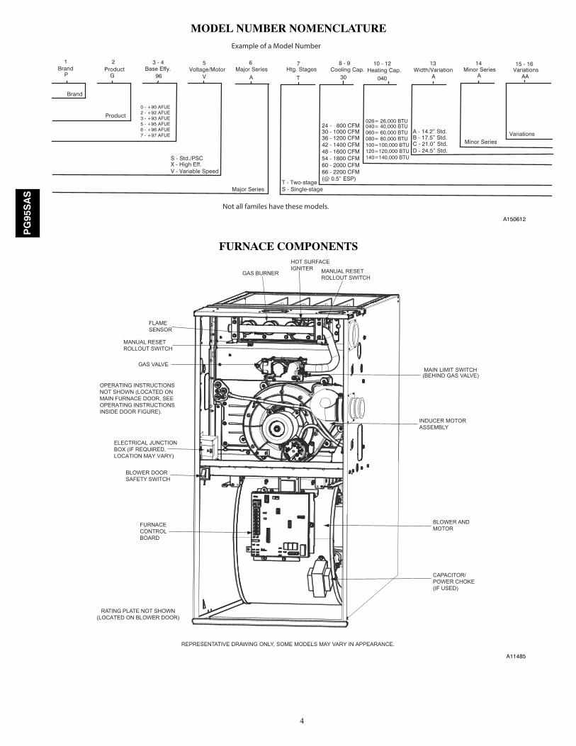
MODEL NUMBER NOMENCLATURE
P 96 V A T 30 040 A A AA
Product
S - Std./PSCX - High Eff.V - Variable Speed
Brand
Major SeriesT - Two-stageS - Single-stage
Minor Series
1Brand
2Product Base Effy.
3 - 4 5Voltage/Motor
6Major Series Htg. Stages
7Cooling Cap.
8 - 9 10 - 12Heating Cap.
13Width/Variation
14Minor Series Variations
15 - 16
G
A - 14.2” Std.B - 17.5” Std.C - 21.0” Std.D - 24.5” Std.
Variations
Not all familes have these models.
040= 40,000 BTU060= 60,000 BTU080= 80,000 BTU100=100,000 BTU120=120,000 BTU140=140,000 BTU
0 - +90 AFUE2 - +92 AFUE3 - +93 AFUE5 - +95 AFUE6 - +96 AFUE7 - +97 AFUE
24 - 800 CFM30 - 1000 CFM36 - 1200 CFM42 - 1400 CFM48 - 1600 CFM54 - 1800 CFM60 - 2000 CFM66 - 2200 CFM(@ 0.5” ESP)
Example of a Model Number
026= 26,000 BTU
A150612
FURNACE COMPONENTS
RATING PLATE NOT SHOWN(LOCATED ON BLOWER DOOR)
GAS VALVEMAIN LIMIT SWITCH(BEHIND GAS VALVE)
REPRESENTATIVE DRAWING ONLY, SOME MODELS MAY VARY IN APPEARANCE.
ELECTRICAL JUNCTIONBOX (IF REQUIRED, LOCATION MAY VARY)
OPERATING INSTRUCTIONSNOT SHOWN (LOCATED ONMAIN FURNACE DOOR, SEE OPERATING INSTRUCTIONS INSIDE DOOR FIGURE).
FURNACECONTROLBOARD
MANUAL RESETROLLOUT SWITCH
FLAMESENSOR
MANUAL RESETROLLOUT SWITCH
GAS BURNER
HOT SURFACEIGNITER
INDUCER MOTORASSEMBLY
BLOWER ANDMOTOR
CAPACITOR/POWER CHOKE(IF USED)
BLOWER DOORSAFETY SWITCH
A11485
PG95SAS
5
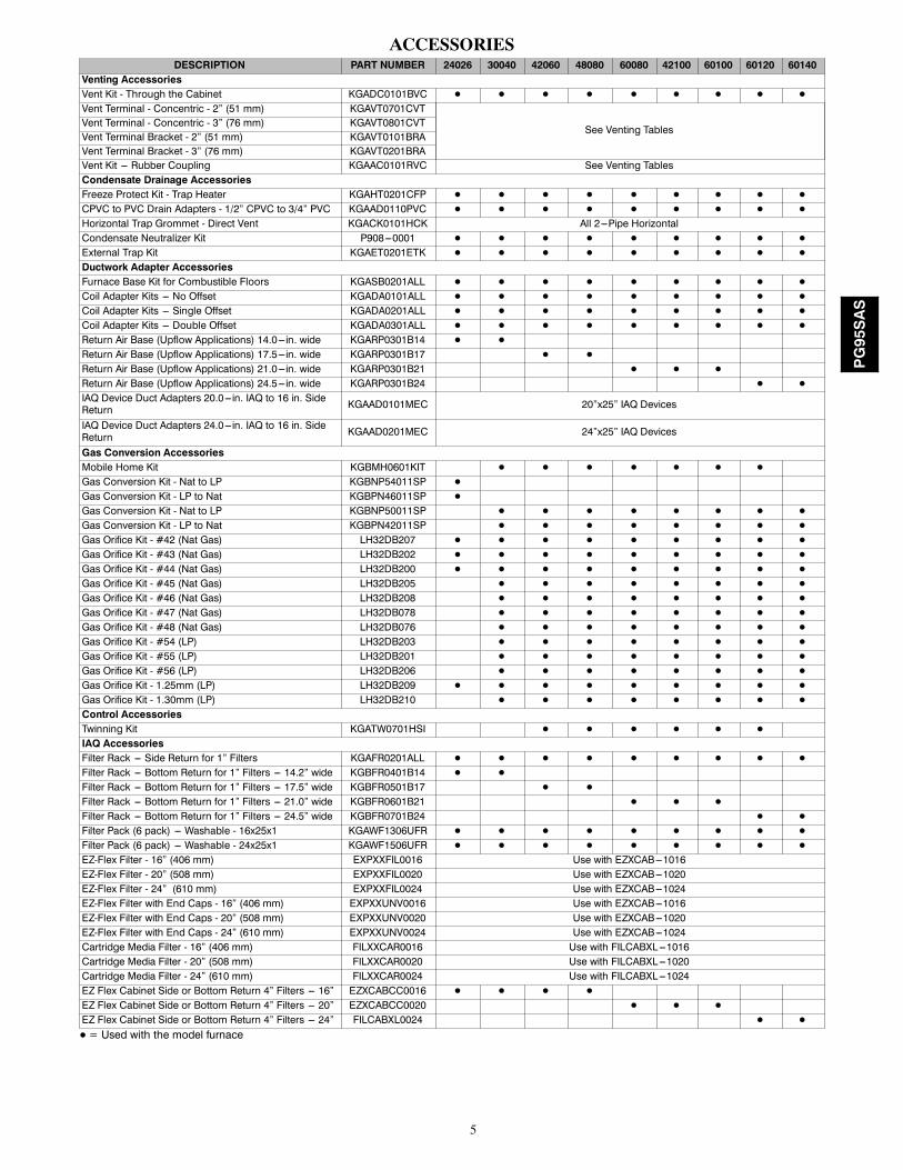
ACCESSORIESDESCRIPTION PART NUMBER 24026 30040 42060 48080 60080 42100 60100 60120 60140
Venting AccessoriesVent Kit - Through the Cabinet KGADC0101BVC D D D D D D D D D
Vent Terminal - Concentric - 2” (51 mm) KGAVT0701CVT
See Venting TablesVent Terminal - Concentric - 3” (76 mm) KGAVT0801CVTVent Terminal Bracket - 2” (51 mm) KGAVT0101BRAVent Terminal Bracket - 3” (76 mm) KGAVT0201BRAVent Kit --- Rubber Coupling KGAAC0101RVC See Venting TablesCondensate Drainage AccessoriesFreeze Protect Kit - Trap Heater KGAHT0201CFP D D D D D D D D D
CPVC to PVC Drain Adapters - 1/2” CPVC to 3/4” PVC KGAAD0110PVC D D D D D D D D D
Horizontal Trap Grommet - Direct Vent KGACK0101HCK All 2---Pipe HorizontalCondensate Neutralizer Kit P908---0001 D D D D D D D D D
External Trap Kit KGAET0201ETK D D D D D D D D D
Ductwork Adapter AccessoriesFurnace Base Kit for Combustible Floors KGASB0201ALL D D D D D D D D D
Coil Adapter Kits --- No Offset KGADA0101ALL D D D D D D D D D
Coil Adapter Kits --- Single Offset KGADA0201ALL D D D D D D D D D
Coil Adapter Kits --- Double Offset KGADA0301ALL D D D D D D D D D
Return Air Base (Upflow Applications) 14.0---in. wide KGARP0301B14 D D
Return Air Base (Upflow Applications) 17.5---in. wide KGARP0301B17 D D
Return Air Base (Upflow Applications) 21.0---in. wide KGARP0301B21 D D D
Return Air Base (Upflow Applications) 24.5---in. wide KGARP0301B24 D D
IAQ Device Duct Adapters 20.0---in. IAQ to 16 in. SideReturn KGAAD0101MEC 20”x25” IAQ Devices
IAQ Device Duct Adapters 24.0---in. IAQ to 16 in. SideReturn KGAAD0201MEC 24”x25” IAQ Devices
Gas Conversion AccessoriesMobile Home Kit KGBMH0601KIT D D D D D D D
Gas Conversion Kit - Nat to LP KGBNP54011SP D
Gas Conversion Kit - LP to Nat KGBPN46011SP D
Gas Conversion Kit - Nat to LP KGBNP50011SP D D D D D D D D
Gas Conversion Kit - LP to Nat KGBPN42011SP D D D D D D D D
Gas Orifice Kit - #42 (Nat Gas) LH32DB207 D D D D D D D D D
Gas Orifice Kit - #43 (Nat Gas) LH32DB202 D D D D D D D D D
Gas Orifice Kit - #44 (Nat Gas) LH32DB200 D D D D D D D D D
Gas Orifice Kit - #45 (Nat Gas) LH32DB205 D D D D D D D D
Gas Orifice Kit - #46 (Nat Gas) LH32DB208 D D D D D D D D
Gas Orifice Kit - #47 (Nat Gas) LH32DB078 D D D D D D D D
Gas Orifice Kit - #48 (Nat Gas) LH32DB076 D D D D D D D D
Gas Orifice Kit - #54 (LP) LH32DB203 D D D D D D D D
Gas Orifice Kit - #55 (LP) LH32DB201 D D D D D D D D
Gas Orifice Kit - #56 (LP) LH32DB206 D D D D D D D D
Gas Orifice Kit - 1.25mm (LP) LH32DB209 D D D D D D D D D
Gas Orifice Kit - 1.30mm (LP) LH32DB210 D D D D D D D D
Control AccessoriesTwinning Kit KGATW0701HSI D D D D D D
IAQ AccessoriesFilter Rack --- Side Return for 1” Filters KGAFR0201ALL D D D D D D D D D
Filter Rack --- Bottom Return for 1” Filters --- 14.2” wide KGBFR0401B14 D D
Filter Rack --- Bottom Return for 1” Filters --- 17.5” wide KGBFR0501B17 D D
Filter Rack --- Bottom Return for 1” Filters --- 21.0” wide KGBFR0601B21 D D D
Filter Rack --- Bottom Return for 1” Filters --- 24.5” wide KGBFR0701B24 D D
Filter Pack (6 pack) --- Washable - 16x25x1 KGAWF1306UFR D D D D D D D D D
Filter Pack (6 pack) --- Washable - 24x25x1 KGAWF1506UFR D D D D D D D D D
EZ-Flex Filter - 16” (406 mm) EXPXXFIL0016 Use with EZXCAB---1016EZ-Flex Filter - 20” (508 mm) EXPXXFIL0020 Use with EZXCAB---1020EZ-Flex Filter - 24” (610 mm) EXPXXFIL0024 Use with EZXCAB---1024EZ-Flex Filter with End Caps - 16” (406 mm) EXPXXUNV0016 Use with EZXCAB---1016EZ-Flex Filter with End Caps - 20” (508 mm) EXPXXUNV0020 Use with EZXCAB---1020EZ-Flex Filter with End Caps - 24” (610 mm) EXPXXUNV0024 Use with EZXCAB---1024Cartridge Media Filter - 16” (406 mm) FILXXCAR0016 Use with FILCABXL---1016Cartridge Media Filter - 20” (508 mm) FILXXCAR0020 Use with FILCABXL---1020Cartridge Media Filter - 24” (610 mm) FILXXCAR0024 Use with FILCABXL---1024EZ Flex Cabinet Side or Bottom Return 4” Filters --- 16” EZXCABCC0016 D D D D
EZ Flex Cabinet Side or Bottom Return 4” Filters --- 20” EZXCABCC0020 D D D
EZ Flex Cabinet Side or Bottom Return 4” Filters --- 24” FILCABXL0024 D D
D = Used with the model furnace
PG95SAS
6
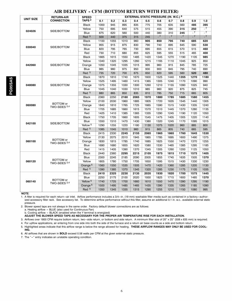
AIR DELIVERY -- CFM (BOTTOM RETURNWITH FILTER)
UNIT SIZE RETURN-AIRCONNECTION
SPEEDTAPS 2
EXTERNAL STATIC PRESSURE (IN. W.C.) 6
0.1 0.2 0.3 0.4 0.5 0.6 0.7 0.8 0.9 1.0
024026 SIDE/BOTTOM
Black 1000 945 895 835 775 705 635 560 485 395Yellow 750 695 640 575 515 455 390 315 250 - 7
Blue 675 620 560 500 440 380 310 245 - 7 - 7
Red 5 500 440 375 315 245 - 7 - 7 - 7 - 7 - 7
030040 SIDE/BOTTOM
Black 1100 1055 1010 960 905 850 795 740 685 620Yellow 955 915 875 830 790 740 695 645 590 530Blue 820 795 765 730 695 655 615 570 515 460Red 730 710 680 655 625 595 555 515 465 400
042060 SIDE/BOTTOM
Black 1665 1615 1550 1485 1420 1345 1270 1190 1105 985Yellow 1340 1320 1295 1260 1215 1165 1110 1045 925 850Orange 1050 1045 1035 1015 995 960 915 845 785 725Blue 985 980 975 950 930 900 845 795 740 690Red 5 735 720 700 675 650 620 595 560 520 480
048080 SIDE/BOTTOM
Black 1870 1810 1740 1670 1600 1525 1440 1355 1270 1180Yellow 1525 1495 1460 1415 1365 1305 1240 1170 1090 990Orange 1375 1355 1330 1300 1260 1210 1155 1090 1025 940Blue 1045 1040 1030 1010 985 960 920 875 825 745Red 5 880 865 850 835 810 785 750 715 665 605
060080 BOTTOM orTWO-SIDES 3,4
Black 2360 2250 2160 2065 1970 1880 1785 1685 1580 1455Yellow 2100 2030 1960 1885 1805 1720 1635 1545 1440 1305Orange 1840 1810 1765 1725 1665 1590 1515 1430 1335 1240Blue 1705 1685 1660 1615 1570 1510 1445 1370 1280 1135Red 1425 1410 1385 1365 1335 1290 1245 1190 1120 1050
042100 SIDE/BOTTOM
Black 1750 1705 1660 1605 1545 1475 1405 1305 1220 1140Blue 1550 1510 1470 1430 1380 1320 1245 1170 1095 1015Yellow 5 1290 1255 1220 1180 1130 1075 1020 960 885 800Red 5 1085 1045 1010 960 915 865 805 740 665 595
060100 BOTTOM orTWO-SIDES 3,4
Black 2415 2330 2245 2155 2065 1965 1865 1760 1645 1530Yellow 2130 2075 2010 1945 1865 1785 1695 1600 1490 1375Orange 1830 1815 1785 1740 1685 1625 1550 1470 1370 1255Blue 1690 1680 1655 1620 1580 1530 1465 1385 1295 1185Red 1415 1405 1390 1370 1345 1305 1260 1200 1125 1050
060120 BOTTOM orTWO-SIDES 3,4
Black 2440 2360 2295 2215 2105 1975 1815 1710 1575 1405Blue 2300 2245 2185 2090 2005 1855 1745 1635 1505 1370Yellow 1805 1780 1750 1705 1650 1595 1515 1430 1330 1230Orange 5 1560 1550 1535 1505 1470 1420 1360 1285 1205 1130Red 5 1390 1385 1370 1345 1320 1285 1230 1175 1105 1035
060140 BOTTOM orTWO-SIDES 3,4
Black 2410 2325 2230 2135 2035 1930 1820 1700 1575 1445Blue 2250 2175 2100 2020 1930 1825 1715 1600 1485 1370Yellow 5 1740 1725 1700 1660 1610 1550 1470 1390 1295 1190Orange 5 1500 1495 1485 1465 1435 1390 1335 1265 1185 1090Red 5 1350 1345 1335 1315 1290 1255 1210 1150 1080 995
NOTE:1. A filter is required for each return ---air inlet. Airflow performance includes a 3/4---in. (19 mm) washable filter media such as contained in a factory---author-ized accessory filter rack. See accessory list. To determine airflow performance without this filter, assume an additional 0.1 in. w.c.. available external staticpressure.
2. Blower speed taps are not always in the same order. Factory default blower connections are as follows:a. Heating airflow --- BLUE (also used for Continuous Fan)b. Cooling airflow --- BLACK (enabled when the Y terminal is energized)ADJUST THE BLOWER SPEED TAPS AS NECESSARY FOR THE PROPER AIR TEMPERATURE RISE FOR EACH INSTALLATION.
3. Airflows over 1800 CFM require bottom return, two---side return, or bottom and side return. A minimum filter size of 20” x 25” (508 x 635 mm) is required.4. For upflow applications, air entering from one side into both the side of the furnace and a return air base counts as a side and bottom return.5. Highlighted areas indicate that this airflow range is below the range allowed for heating. THESE AIRFLOW RANGES MAY ONLY BE USED FOR COOL-ING.
6. All airflows that are shown in BOLD exceed 0.58 watts per CFM at the given external static pressure.7. The “---” entry indicates an unstable operating condition.
PG95SAS
7
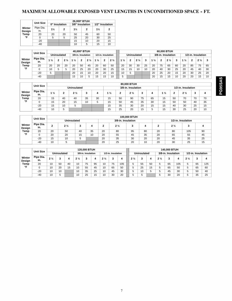
MAXIMUM ALLOWABLE EXPOSED VENT LENGTHS IN UNCONDITIONED SPACE -- FT.
WinterDesignTemp
°F
Unit Size26,000* BTUH
0" Insulation 3/8" Insulation 1/2" InsulationPipe Dia.
In. 1½ 2 1½ 2 1½ 2
20 20 20 50 45 60 500 5 5 25 20 30 25
-20 15 10 20 15-40 10 5 15 10
WinterDesignTemp
°F
Unit Size40,000* BTUH 60,000 BTUH
Uninsulated 3/8-in. Insulation 1/2-in. Insulation Uninsulated 3/8-in. Insulation 1/2-in. InsulationPipe Dia.
in. 1 ½ 2 2 ½ 1 ½ 2 2 ½ 1 ½ 2 2 ½ 1 ½ 2 2 ½ 3 1 ½ 2 2 ½ 3 1 ½ 2 2 ½ 3
20 20 20 20 20 50 45 20 60 50 20 30 30 25 20 75 65 60 20 85 75 650 10 5 5 20 25 20 20 30 25 15 15 10 10 20 40 30 25 20 45 40 30
-20 5 20 15 10 20 20 15 10 5 20 25 20 15 20 30 25 20-40 15 10 5 15 15 10 5 20 15 15 10 20 20 15 10
WinterDesignTemp
°F
Unit Size80,000 BTUH
Uninsulated 3/8-in. Insulation 1/2-in. InsulationPipe Dia.
in. 1 ½ 2 2 ½ 3 4 1 ½ 2 2 ½ 3 4 1 ½ 2 2 ½ 3 4
20 15 40 40 35 30 15 50 90 75 65 15 50 70 70 700 15 20 15 10 5 15 50 45 35 30 15 50 50 40 35
-20 15 10 5 15 35 30 20 15 15 40 30 25 15-40 10 5 15 25 20 15 5 15 30 25 20 10
WinterDesignTemp
°F
Unit Size100,000 BTUH
Uninsulated 3/8-in. Insulation 1/2-in. InsulationPipe Dia.
in. 2 2 ½ 3 4 2 2 ½ 3 4 2 2 ½ 3 4
20 20 50 40 35 20 80 95 80 20 80 105 900 20 20 15 10 20 55 45 35 20 65 55 45
-20 15 10 5 20 35 30 20 20 45 35 25-40 10 5 20 25 20 10 20 30 25 15
WinterDesignTemp
°F
Unit Size120,000 BTUH 140,000 BTUH
Uninsulated 3/8-in. Insulation 1/2-in. Insulation Uninsulated 3/8-in. Insulation 1/2-in. InsulationPipe Dia.
in. 2 ½ 3 4 2 ½ 3 4 2 ½ 3 4 2 ½ 3 4 2 ½ 3 4 2 ½ 3 4
20 10 50 40 10 75 95 10 75 105 5 55 50 5 65 105 5 65 1250 10 20 15 10 55 45 10 65 50 5 25 15 5 65 50 5 65 60
-20 10 10 10 35 25 10 45 30 5 10 5 5 45 30 5 50 40-40 10 5 10 25 15 10 30 20 5 5 5 30 20 5 35 25
PG95SAS
8
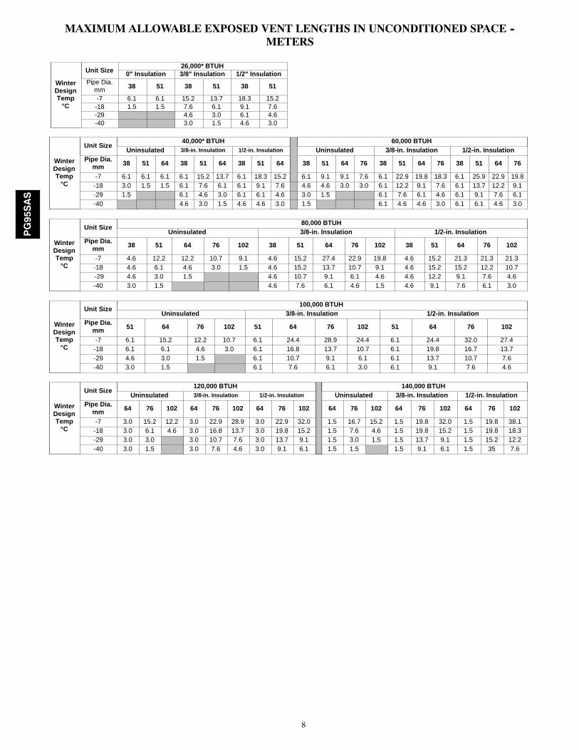
MAXIMUM ALLOWABLE EXPOSED VENT LENGTHS IN UNCONDITIONED SPACE --METERS
WinterDesignTemp
°C
Unit Size26,000* BTUH
0" Insulation 3/8" Insulation 1/2" InsulationPipe Dia.
mm 38 51 38 51 38 51
-7 6.1 6.1 15.2 13.7 18.3 15.2-18 1.5 1.5 7.6 6.1 9.1 7.6-29 4.6 3.0 6.1 4.6-40 3.0 1.5 4.6 3.0
WinterDesignTemp
°C
Unit Size40,000* BTUH 60,000 BTUH
Uninsulated 3/8-in. Insulation 1/2-in. Insulation Uninsulated 3/8-in. Insulation 1/2-in. InsulationPipe Dia.
mm 38 51 64 38 51 64 38 51 64 38 51 64 76 38 51 64 76 38 51 64 76
-7 6.1 6.1 6.1 6.1 15.2 13.7 6.1 18.3 15.2 6.1 9.1 9.1 7.6 6.1 22.9 19.8 18.3 6.1 25.9 22.9 19.8-18 3.0 1.5 1.5 6.1 7.6 6.1 6.1 9.1 7.6 4.6 4.6 3.0 3.0 6.1 12.2 9.1 7.6 6.1 13.7 12.2 9.1-29 1.5 6.1 4.6 3.0 6.1 6.1 4.6 3.0 1.5 6.1 7.6 6.1 4.6 6.1 9.1 7.6 6.1-40 4.6 3.0 1.5 4.6 4.6 3.0 1.5 6.1 4.6 4.6 3.0 6.1 6.1 4.6 3.0
WinterDesignTemp
°C
Unit Size80,000 BTUH
Uninsulated 3/8-in. Insulation 1/2-in. InsulationPipe Dia.
mm 38 51 64 76 102 38 51 64 76 102 38 51 64 76 102
-7 4.6 12.2 12.2 10.7 9.1 4.6 15.2 27.4 22.9 19.8 4.6 15.2 21.3 21.3 21.3-18 4.6 6.1 4.6 3.0 1.5 4.6 15.2 13.7 10.7 9.1 4.6 15.2 15.2 12.2 10.7-29 4.6 3.0 1.5 4.6 10.7 9.1 6.1 4.6 4.6 12.2 9.1 7.6 4.6-40 3.0 1.5 4.6 7.6 6.1 4.6 1.5 4.6 9.1 7.6 6.1 3.0
WinterDesignTemp
°C
Unit Size100,000 BTUH
Uninsulated 3/8-in. Insulation 1/2-in. InsulationPipe Dia.
mm 51 64 76 102 51 64 76 102 51 64 76 102
-7 6.1 15.2 12.2 10.7 6.1 24.4 28.9 24.4 6.1 24.4 32.0 27.4-18 6.1 6.1 4.6 3.0 6.1 16.8 13.7 10.7 6.1 19.8 16.7 13.7-29 4.6 3.0 1.5 6.1 10.7 9.1 6.1 6.1 13.7 10.7 7.6-40 3.0 1.5 6.1 7.6 6.1 3.0 6.1 9.1 7.6 4.6
WinterDesignTemp
°C
Unit Size120,000 BTUH 140,000 BTUH
Uninsulated 3/8-in. Insulation 1/2-in. Insulation Uninsulated 3/8-in. Insulation 1/2-in. InsulationPipe Dia.
mm 64 76 102 64 76 102 64 76 102 64 76 102 64 76 102 64 76 102
-7 3.0 15.2 12.2 3.0 22.9 28.9 3.0 22.9 32.0 1.5 16.7 15.2 1.5 19.8 32.0 1.5 19.8 38.1-18 3.0 6.1 4.6 3.0 16.8 13.7 3.0 19.8 15.2 1.5 7.6 4.6 1.5 19.8 15.2 1.5 19.8 18.3-29 3.0 3.0 3.0 10.7 7.6 3.0 13.7 9.1 1.5 3.0 1.5 1.5 13.7 9.1 1.5 15.2 12.2-40 3.0 1.5 3.0 7.6 4.6 3.0 9.1 6.1 1.5 1.5 1.5 9.1 6.1 1.5 35 7.6
PG95SAS
9
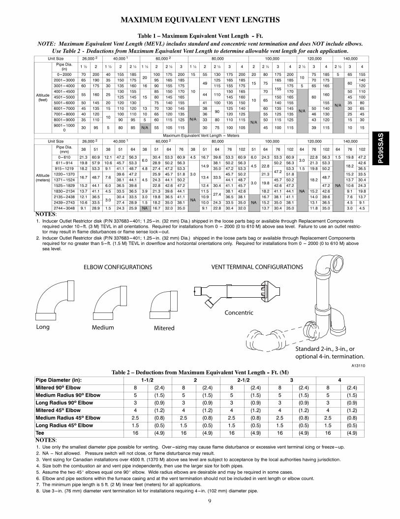
MAXIMUM EQUIVALENT VENT LENGTHS
Table 1 – Maximum Equivalent Vent Length -- Ft.NOTE: Maximum Equivalent Vent Length (MEVL) includes standard and concentric vent termination and does NOT include elbows.
Use Table 2 - Deductions from Maximum Equivalent Vent Length to determine allowable vent length for each application.Unit Size 26,000 2 40,000 1 60,000 2 80,000 100,000 120,000 140,000
Altitude(feet)
Pipe Dia.(in) 1 ½ 2 1 ½ 2 2 ½ 1 ½ 2 2 ½ 3 1 ½ 2 2 ½ 3 4 2 2 ½ 3 4 2 ½ 3 4 2 ½ 3 4
0---2000 70 200 40 155 18520
100 175 200 15 55 130 175 200 20 80 175 20010
75 185 5 65 1552001---3000 65 190 35 150 175 95 165 185
10
49125 165 185
15 75165 185 70 175
N/A
60140
3001---4000 60 175 30 135 160 16 90 155 175 115 155 175155
175 5 65 165 1204001---4500
55 160 25130 155
1585 150 170
44 110150 165
10
70 170
N/A
60160
50 1104501---5000 125 145 80 145 165 145 160
65150 165 45 100
5001---6000 50 145 20 120 130 75 140 155 41 100 135 150 140 155 155 35 806001---7000 45 135 15 110 120 13 70 130 145
N/A
3890
125 140 60 135 145 50 140 30 657001---8000 40 120
10100 110 10 65 120 135 36 120 125
N/A
55 125 135 46 130 25 458001---9000 35 110 90 95 5 60 115 125 33 80 110 115 50 115 125 43 120 15 309001---1000
0 30 95 5 80 85 N/A 55 105 115 30 75 100 105 45 100 115 39 115 10 15
Maximum Equivalent Vent Length --- MetersUnit Size 26,000 2 40,000 1 60,000 2 80,000 100,000 120,000 140,000
Altitude(meters)
Pipe Dia.(mm) 38 51 38 51 64 38 51 64 76 38 51 64 76 102 51 64 76 102 64 76 102 64 76 102
0---610 21.3 60.9 12.1 47.2 56.36.0
30.4 53.3 60.9 4.5 16.7 39.6 53.3 60.9 6.0 24.3 53.3 60.93.0
22.8 56.3 1.5 19.8 47.2611---914 19.8 57.9 10.6 45.7 53.3 28.9 50.2 56.3
3.0
14.938.1 50.2 56.3
4.5 22.850.2 56.3 21.3 53.3
NA
18.242.6
915---1219 18.2 53.3 9.1 41.1 48.7 4.8 27.4 47.2 53.3 35.0 47.2 53.347.2
53.3 1.5 19.8 50.2 36.51220---1370
16.7 48.7 7.639.6 47.2
4.525.9 45.7 51.8
13.4 33.545.7 50.2
3.0
21.3 51.8
NA
18.248.7
15.2 33.51371---1524 38.1 44.1 24.3 44.1 50.2 44.1 48.7
19.845.7 50.2 13.7 30.4
1525---1829 15.2 44.1 6.0 36.5 39.6 22.8 42.6 47.2 12.4 30.4 41.1 45.7 42.6 47.2 47.2 10.6 24.31830---2134 13.7 41.1 4.5 33.5 36.5 3.9 21.3 39.6 44.1
NA
11.527.4
38.1 42.6 18.2 41.1 44.1 15.2 42.6 9.1 19.82135---2438 12.1 36.5
3.030.4 33.5 3.0 19.8 36.5 41.1 10.9 36.5 38.1
NA16.7 38.1 41.1 14.0 39.6 7.6 13.7
2439---2743 10.6 33.5 27.4 28.9 1.5 18.2 35.0 38.1 10.0 24.3 33.5 35.0 15.2 35.0 38.1 13.1 36.5 4.5 9.12744---3048 9.1 28.9 1.5 24.3 25.9 NA 16.7 32.0 35.0 9.1 22.8 30.4 32.0 13.7 30.4 35.0 11.8 35.0 3.0 4.5
NOTES:1. Inducer Outlet Restrictor disk (P/N 337683---401; 1.25---in. (32 mm) Dia.) shipped in the loose parts bag or available through Replacement Componentsrequired under 10---ft. (3 M) TEVL in all orientations. Required for installations from 0 --- 2000 (0 to 610 M) above sea level. Failure to use an outlet restric-tor may result in flame disturbances or flame sense lock---out.
2. Inducer Outlet Restrictor disk (P/N 337683---401; 1.25---in. (32 mm) Dia.) shipped in the loose parts bag or available through Replacement Componentsrequired for no greater than 5---ft. (1.5 M) TEVL in downflow and horizontal orientations only. Required for installations from 0 --- 2000 (0 to 610 M) abovesea level.
Long Medium Mitered
Concentric
Standard 2-in., 3-in., or optional 4-in. termination.
ELBOW CONFIGURATIONS VENT TERMINAL CONFIGURATIONS
A13110
Table 2 – Deductions from Maximum Equivalent Vent Length -- Ft. (M)Pipe Diameter (in): 1-1/2 2 2-1/2 3 4Mitered 90º Elbow 8 (2.4) 8 (2.4) 8 (2.4) 8 (2.4) 8 (2.4)Medium Radius 90º Elbow 5 (1.5) 5 (1.5) 5 (1.5) 5 (1.5) 5 (1.5)Long Radius 90º Elbow 3 (0.9) 3 (0.9) 3 (0.9) 3 (0.9) 3 (0.9)Mitered 45º Elbow 4 (1.2) 4 (1.2) 4 (1.2) 4 (1.2) 4 (1.2)Medium Radius 45º Elbow 2.5 (0.8) 2.5 (0.8) 2.5 (0.8) 2.5 (0.8) 2.5 (0.8)Long Radius 45º Elbow 1.5 (0.5) 1.5 (0.5) 1.5 (0.5) 1.5 (0.5) 1.5 (0.5)Tee 16 (4.9) 16 (4.9) 16 (4.9) 16 (4.9) 16 (4.9)NOTES:1. Use only the smallest diameter pipe possible for venting. Over ---sizing may cause flame disturbance or excessive vent terminal icing or freeze---up.2. NA --- Not allowed. Pressure switch will not close, or flame disturbance may result.3. Vent sizing for Canadian installations over 4500 ft. (1370 M) above sea level are subject to acceptance by the local authorities having jurisdiction.4. Size both the combustion air and vent pipe independently, then use the larger size for both pipes.5. Assume the two 45_ elbows equal one 90_ elbow. Wide radius elbows are desirable and may be required in some cases.6. Elbow and pipe sections within the furnace casing and at the vent termination should not be included in vent length or elbow count.7. The minimum pipe length is 5 ft. (2 M) linear feet (meters) for all applications.8. Use 3---in. (76 mm) diameter vent termination kit for installations requiring 4---in. (102 mm) diameter pipe.
PG95SAS
10
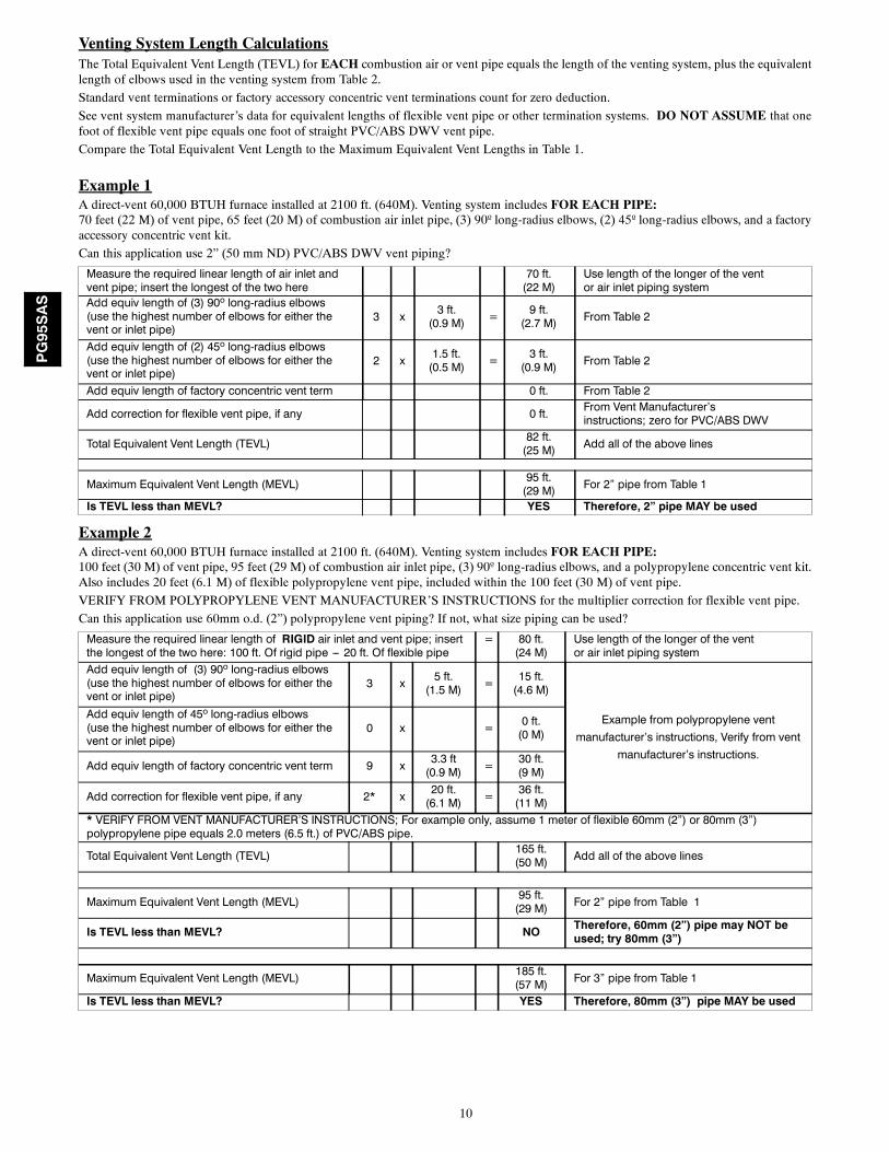
Venting System Length CalculationsThe Total Equivalent Vent Length (TEVL) for EACH combustion air or vent pipe equals the length of the venting system, plus the equivalentlength of elbows used in the venting system from Table 2.
Standard vent terminations or factory accessory concentric vent terminations count for zero deduction.
See vent system manufacturer’s data for equivalent lengths of flexible vent pipe or other termination systems. DO NOT ASSUME that onefoot of flexible vent pipe equals one foot of straight PVC/ABS DWV vent pipe.
Compare the Total Equivalent Vent Length to the Maximum Equivalent Vent Lengths in Table 1.
Example 1A direct-vent 60,000 BTUH furnace installed at 2100 ft. (640M). Venting system includes FOR EACH PIPE:70 feet (22 M) of vent pipe, 65 feet (20 M) of combustion air inlet pipe, (3) 90º long-radius elbows, (2) 45º long-radius elbows, and a factoryaccessory concentric vent kit.
Can this application use 2” (50 mm ND) PVC/ABS DWV vent piping?
Measure the required linear length of air inlet andvent pipe; insert the longest of the two here
70 ft.(22 M)
Use length of the longer of the ventor air inlet piping system
Add equiv length of (3) 90º long-radius elbows(use the highest number of elbows for either thevent or inlet pipe)
3 x 3 ft.(0.9 M) = 9 ft.
(2.7 M) From Table 2
Add equiv length of (2) 45º long-radius elbows(use the highest number of elbows for either thevent or inlet pipe)
2 x 1.5 ft.(0.5 M) = 3 ft.
(0.9 M) From Table 2
Add equiv length of factory concentric vent term 0 ft. From Table 2
Add correction for flexible vent pipe, if any 0 ft. From Vent Manufacturer’sinstructions; zero for PVC/ABS DWV
Total Equivalent Vent Length (TEVL) 82 ft.(25 M) Add all of the above lines
Maximum Equivalent Vent Length (MEVL) 95 ft.(29 M) For 2” pipe from Table 1
Is TEVL less than MEVL? YES Therefore, 2” pipe MAY be used
Example 2A direct-vent 60,000 BTUH furnace installed at 2100 ft. (640M). Venting system includes FOR EACH PIPE:100 feet (30 M) of vent pipe, 95 feet (29 M) of combustion air inlet pipe, (3) 90º long-radius elbows, and a polypropylene concentric vent kit.Also includes 20 feet (6.1 M) of flexible polypropylene vent pipe, included within the 100 feet (30 M) of vent pipe.
VERIFY FROM POLYPROPYLENE VENT MANUFACTURER’S INSTRUCTIONS for the multiplier correction for flexible vent pipe.
Can this application use 60mm o.d. (2”) polypropylene vent piping? If not, what size piping can be used?
Measure the required linear length of RIGID air inlet and vent pipe; insertthe longest of the two here: 100 ft. Of rigid pipe --- 20 ft. Of flexible pipe
= 80 ft.(24 M)
Use length of the longer of the ventor air inlet piping system
Add equiv length of (3) 90º long-radius elbows(use the highest number of elbows for either thevent or inlet pipe)
3 x 5 ft.(1.5 M) = 15 ft.
(4.6 M)
Example from polypropylene ventmanufacturer’s instructions, Verify from vent
manufacturer’s instructions.
Add equiv length of 45º long-radius elbows(use the highest number of elbows for either thevent or inlet pipe)
0 x = 0 ft.(0 M)
Add equiv length of factory concentric vent term 9 x 3.3 ft(0.9 M) = 30 ft.
(9 M)
Add correction for flexible vent pipe, if any 2* x 20 ft.(6.1 M) = 36 ft.
(11 M)* VERIFY FROM VENT MANUFACTURER’S INSTRUCTIONS; For example only, assume 1 meter of flexible 60mm (2”) or 80mm (3”)polypropylene pipe equals 2.0 meters (6.5 ft.) of PVC/ABS pipe.
Total Equivalent Vent Length (TEVL) 165 ft.(50 M) Add all of the above lines
Maximum Equivalent Vent Length (MEVL) 95 ft.(29 M) For 2” pipe from Table 1
Is TEVL less than MEVL? NO Therefore, 60mm (2”) pipe may NOT beused; try 80mm (3”)
Maximum Equivalent Vent Length (MEVL) 185 ft.(57 M) For 3” pipe from Table 1
Is TEVL less than MEVL? YES Therefore, 80mm (3”) pipe MAY be used
PG95SAS
11
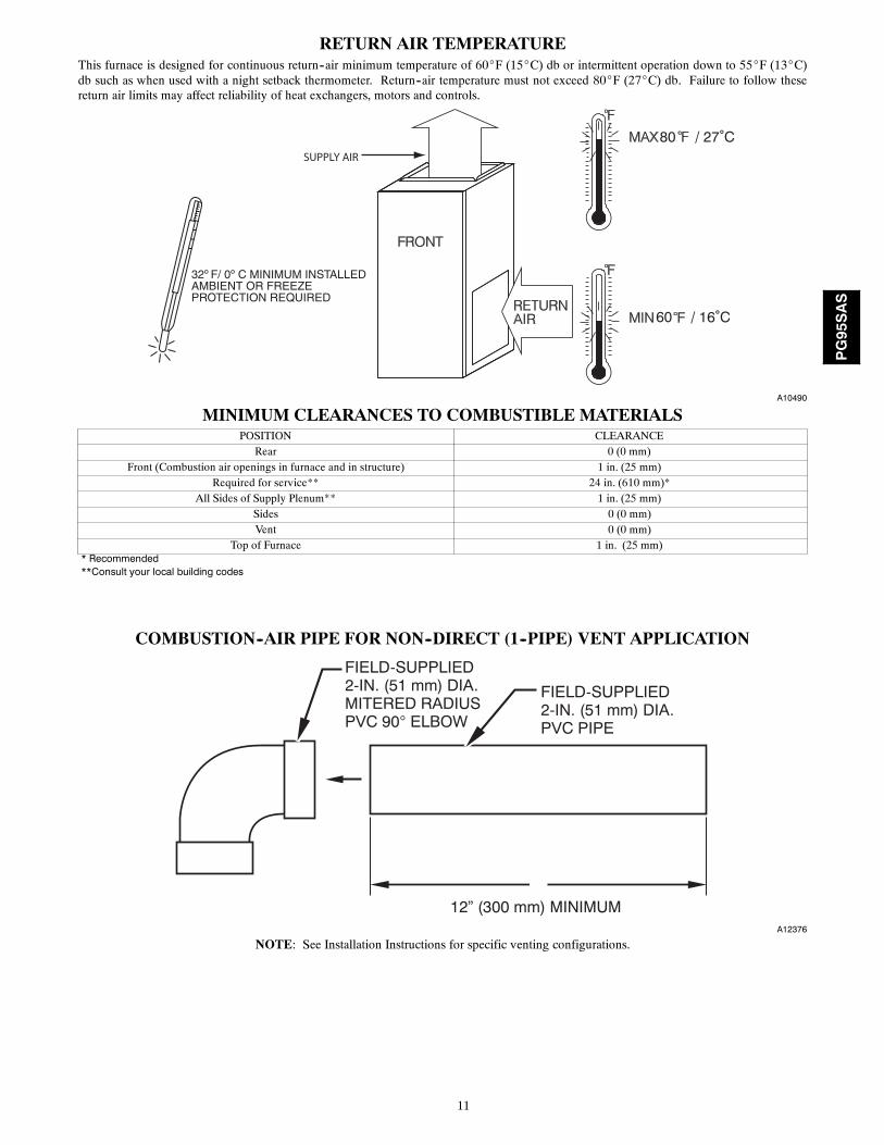
RETURN AIR TEMPERATUREThis furnace is designed for continuous return--air minimum temperature of 60_F (15_C) db or intermittent operation down to 55_F (13_C)db such as when used with a night setback thermometer. Return--air temperature must not exceed 80_F (27_C) db. Failure to follow thesereturn air limits may affect reliability of heat exchangers, motors and controls.
60
80 / 27˚C
/ 16˚C
SUPPLY AIR
A10490
MINIMUM CLEARANCES TO COMBUSTIBLE MATERIALSPOSITION CLEARANCE
Rear 0 (0 mm)Front (Combustion air openings in furnace and in structure) 1 in. (25 mm)
Required for service** 24 in. (610 mm)*All Sides of Supply Plenum** 1 in. (25 mm)
Sides 0 (0 mm)Vent 0 (0 mm)
Top of Furnace 1 in. (25 mm)* Recommended**Consult your local building codes
COMBUSTION--AIR PIPE FOR NON--DIRECT (1--PIPE) VENT APPLICATION
FIELD-SUPPLIED2-IN. (51 mm) DIA.PVC PIPE
FIELD-SUPPLIED2-IN. (51 mm) DIA.MITERED RADIUSPVC 90° ELBOW
12” (300 mm) MINIMUMA12376
NOTE: See Installation Instructions for specific venting configurations.
PG95SAS
12
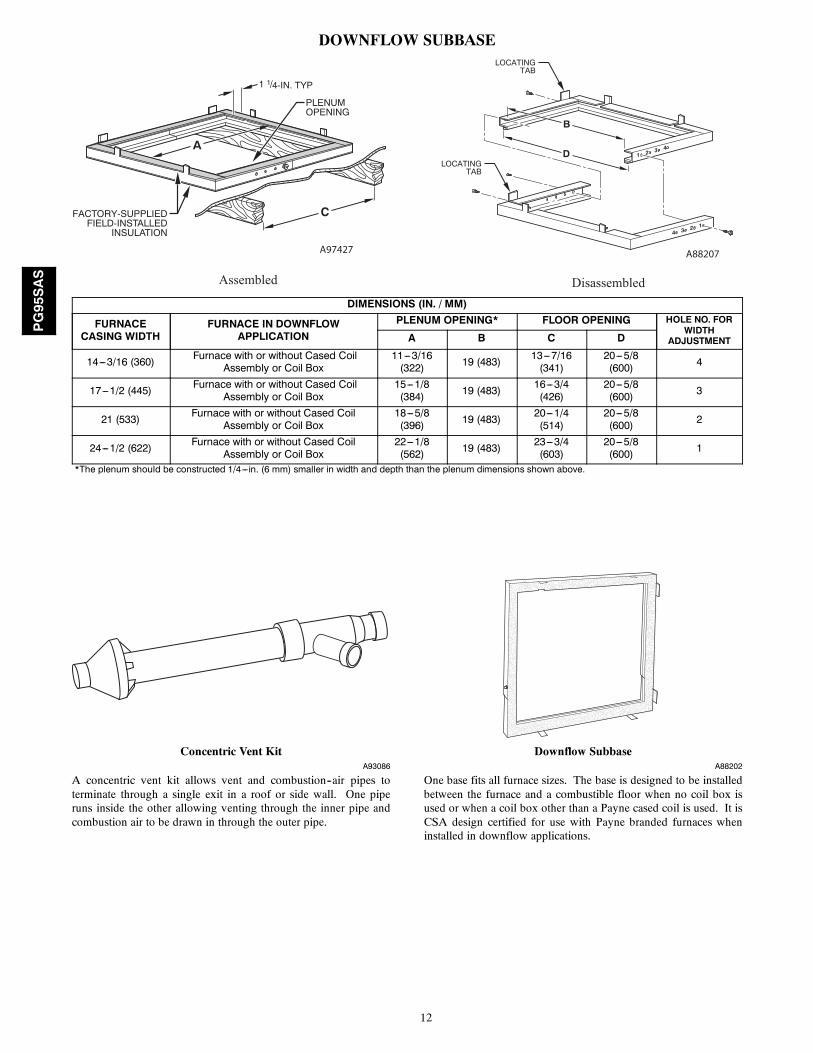
DOWNFLOW SUBBASELOCATING
TAB
LOCATINGTAB
1 2 3 4
4 3 2 1
B
D
C
A
1 1/4-IN. TYP
PLENUMOPENING
FACTORY-SUPPLIEDFIELD-INSTALLED
INSULATION
Assembled Disassembled
A97427 A88207
DIMENSIONS (IN. / MM)
FURNACECASING WIDTH
FURNACE IN DOWNFLOWAPPLICATION
PLENUM OPENING* FLOOR OPENING HOLE NO. FORWIDTH
ADJUSTMENTA B C D
14---3/16 (360) Furnace with or without Cased CoilAssembly or Coil Box
11---3/16(322) 19 (483) 13---7/16
(341)20---5/8(600) 4
17---1/2 (445) Furnace with or without Cased CoilAssembly or Coil Box
15---1/8(384) 19 (483) 16---3/4
(426)20---5/8(600) 3
21 (533) Furnace with or without Cased CoilAssembly or Coil Box
18---5/8(396) 19 (483) 20---1/4
(514)20---5/8(600) 2
24---1/2 (622) Furnace with or without Cased CoilAssembly or Coil Box
22---1/8(562) 19 (483) 23---3/4
(603)20---5/8(600) 1
*The plenum should be constructed 1/4---in. (6 mm) smaller in width and depth than the plenum dimensions shown above.
Concentric Vent KitA93086
A concentric vent kit allows vent and combustion--air pipes toterminate through a single exit in a roof or side wall. One piperuns inside the other allowing venting through the inner pipe andcombustion air to be drawn in through the outer pipe.
Downflow SubbaseA88202
One base fits all furnace sizes. The base is designed to be installedbetween the furnace and a combustible floor when no coil box isused or when a coil box other than a Payne cased coil is used. It isCSA design certified for use with Payne branded furnaces wheninstalled in downflow applications.
PG95SAS
13
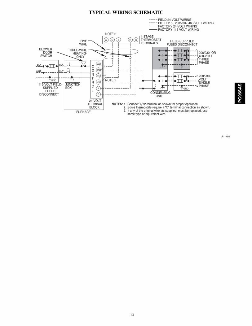
TYPICAL WIRING SCHEMATIC
115-VOLT FIELD-SUPPLIED
FUSEDDISCONNECT
JUNCTIONBOX
24-VOLTTERMINALBLOCK
THREE-WIREHEATING-
ONLY
FIVEWIRE
NOTE 2
NOTE 1
1-STAGETHERMOSTATTERMINALS
FIELD-SUPPLIEDFUSED DISCONNECT
CONDENSINGUNIT
FURNACE
COM
R
W C Y R G
GND
GND
FIELD 24-VOLT WIRINGFIELD 115-, 208/230-, 460-VOLT WIRINGFACTORY 24-VOLT WIRINGFACTORY 115-VOLT WIRING
Connect Y/Y2-terminal as shown for proper operation.Some thermostats require a "C" terminal connection as shown.If any of the original wire, as supplied, must be replaced, usesame type or equivalent wire.
208/230- OR460-VOLTTHREEPHASE
208/230-VOLTSINGLEPHASE
WHT
BLK
WHT
BLK
W/W1
W2
Y/Y2
G
NOTES: 1.2.3.
BLOWERDOOR
SWITCH
CONTROL
A11401
PG95SAS
14
DIMENSIONAL DRAWING
6 1
5/1
6[1
76
.1]
3[7
6.2
]
3[7
6.2
]
6 1
1/1
6[1
70
.1]
23
5/1
6[5
92
.9]
25
1/8
[63
8.7
]
26
3/8
[67
0.0
]
26
11
/16
[67
8.1
]
21
[53
4.0
] 26
5/1
6[6
68
.8]
17
5/1
6[4
39
.2]
16
9/1
6[4
20
.9]
20
1/4
[51
3.9
]2
5 3
/16
[63
9.1
]28
3/1
6[7
15
.9]
28
5/8
[72
6.4
]
32
5/8
[82
9.5
]
28
3/4
[73
0.5
]
26
3/8
[66
9.9
]
26
11
/16
[67
8.1
]
21
15
/16
[55
7.4
]
21
1/1
6[5
35
.8]
26
5/1
6[6
68
.8]
3[7
6.2
]A
IR IN
TA
KE
1 3
/4[4
4.5
]G
AS
CO
NN
7/8
[22
.2]
7/8
[22
.2]
PO
WE
R C
ON
N
7/8
[22
.2]
TH
ER
MO
ST
AT
EN
TR
Y
7/8
[22
.2]
3[7
6.2
]A
IR IN
TA
KE
1 3
/4[4
4.5
]G
AS
CO
NN
7/8
[22
.2]
7/8
[22
.2]
3[7
6.2
]
7/8
[22
.2]
7/8
[22
.2]
TH
ER
MO
ST
AT
EN
TR
Y2
2 1
5/1
6[5
81
.9]
16
9/1
6[4
20
.9]
17
7/1
6[4
42
.3]
20
1/4
[51
3.9
]
24
[60
9.7
]
28
3/8
[72
0.4
]
28
5/8
[72
6.9
]
29
13
/16
[75
7]
23
3/8
[59
2.0
]
3[7
6.2
]V
EN
T
1 (
BO
TH
SID
ES
)[2
5.4
]
D
2 3
/10
[58
.4]
CB
OT
TO
M R
ET
UR
NW
IDT
H
11
/16
[17
.5]
11
/16
[17
.5]
BO
UT
LET
WID
TH
A
22
[55
8.3
] (B
OT
H S
IDE
S)
14
13
/16
[37
6.3
]
35
[88
9.0
]
5/8
[15
.8]
1 5
/16
[33
.3]
29
1/2
[74
9.3
]
19
1/8
[48
5.8
]
20
5/8
[52
2.7
]
23
7/1
6[5
95
.6]
[10
1.6
]4
[63
.5]
2 1
/2
18
1/1
6[4
58
.6]
2 1
/2[6
3.5
]4
[10
1.6
]
20
5/8
[52
2.7
]
BO
TT
OM
INLE
T 2
1 5
/8 [
54
9.5
]
6 1
/16
[15
4.0
]
PAR
T NU
MBE
R
S
D502
4-4
SH
T 1
RE
V E N
EXT
SHEE
T
2
VE
NT
AIR
INT
AK
E
AIR
FLO
WA
IR F
LOW
SID
E IN
LET
SID
E IN
LET
CO
ND
EN
SA
TE
DR
AIN
TR
AP
LO
CA
TIO
N
NO
TE
: ALL
DIM
EN
SIO
NS
IN IN
CH
[M
M]
[22
.2]
7/8
7/8
[22
.2]
PO
WE
R C
ON
N
AIR
FLO
W
SE
E N
OT
E #
3
NO
TE
S:
1. D
oo
rs m
ay
va
ry b
y m
od
el.
2. M
inim
um
re
turn
-air
op
en
ing
s a
t fu
rna
ce, b
ase
d o
n m
eta
l du
ct. I
f fl
ex
du
ct is
use
d,
s
ee
fle
x d
uct
ma
nu
fact
ure
r's
reco
mm
en
da
tio
ns
for
eq
uiv
ale
nt
dia
me
ters
. a
. Fo
r 8
00
CF
M-1
6-i
n. (
40
6 m
m)
rou
nd
or
14
1/2
x 1
2-i
n. (
36
8 x
30
5 m
m)
rect
an
gle
. b
. Fo
r 1
20
0 C
FM
-20
-in
. (5
08
mm
) ro
un
d o
r 1
4 1
/2 x
19
1/2
-in
. (3
68
x 4
95
mm
) re
cta
ng
le.
c. F
or
16
00
CF
M-2
2-i
n. (
55
9 m
m)
rou
nd
or
14
1/2
x 2
2 1
/16
-in
. (3
68
x 5
60
mm
) re
cta
ng
le.
d. R
etu
rn a
ir a
bo
ve
18
00
CF
M a
t 0
.5 in
. w.c
. ES
P o
n 2
4.5
" ca
sin
g, r
eq
uir
es
on
e o
f th
e f
ollo
win
g
con
fig
ura
tio
ns:
2 s
ide
s, 1
sid
e a
nd
a b
ott
om
or
bo
tto
m o
nly
. Se
e A
ir D
eliv
ery
ta
ble
in t
his
d
ocu
me
nt
for
spe
cifi
c u
se t
o a
llow
fo
r su
ffici
en
t a
irfl
ow
to
th
e f
urn
ace
.3
. Ve
nt
an
d C
om
bu
stio
n a
ir p
ipe
s th
rou
gh
blo
we
r co
mp
art
me
nt
mu
st
use
acc
ess
ory
“V
en
t K
it -
Th
rou
gh
th
e C
ab
ine
t”. S
ee
acc
ess
ory
list
fo
r
cu
rre
nt
pa
rt n
um
be
r.
TO
P V
IEW
A12267
PG95SASFURNACE SIZE
A B C D SHIP WT.LB (KG)CABINET WIDTH OUTLET WIDTH BOTTOM INLET WIDTH AIR INTAKE
2402614---3/16 (361) 12---1/2 (319) 12---9/16 (322) 7---1/8 (181)
118.0 (53.5)30040 123.0 (55.4)42060
17---1/2 (445) 15---7/8 (403) 16 (406) 8---3/4 (222)144.0 (64.8)
48080 154.0 (69.3)60080
21 (533) 19---3/8 (492) 19---1/2 (495) 10---1/2 (267)161.5 (72.7)
42100 168.5 (75.8)60100 168.5 (75.8)60120
24---1/2 (622) 22---7/8 (581) 23 (584) 12---1/4 (311)186.0 (83.7)
60140 190.0 (85.5)
PG95SAS
15
GUIDE SPECIFICATIONSGeneralSystem DescriptionFurnish a ______________________ 4--way multipoise gas--firedcondensing furnace for use with natural gas or propane (factory--authorized conversion kit required for propane).
Quality AssuranceUnit will be designed, tested and constructed to the current ANSI Z21.47/CSA 2.3 design standard for gas--fired central furnaces.
Unit will be third party certified by CSA to the current ANSI Z21.47/CSA 2.3 design standard for gas--fired central furnaces. Unitwill carry the CSA Blue StarR and Blue FlameR labels. Unitefficiency testing will be performed per the current DOE testprocedure as listed in the Federal Register.
Unit will be certified for capacity and efficiency and listed in thelatest AHRI Consumer’s Directory of Certified Efficiency Ratings.
Unit will carry the current Federal Trade Commission EnergyGuide efficiency label.
Delivery, Storage, and HandlingUnit will be shipped as single package only and is stored andhandled per unit manufacturer’s recommendations.
Warranty (for inclusion by specifying engineer)U.S. and Canada only. Warranty certificate available upon request.
EquipmentBlower Wheel and PSC Blower Motor
Galvanized blower wheel shall be centrifugal type, statically anddynamically balanced. Blower motor of PSC type shall bepermanently lubricated with sleeve bearings, of _______hp, andhave multiple speeds from 600--1200 RPM operating only whenmotor inputs are provided. Blower motor shall be direct drive andsoft mounted to the blower housing to reduce vibrationtransmission.
Filters
Furnace shall have reusable--type filters. Filter shall be ______ in.(mm) X ________ in. (mm). An accessory highly efficient MediaFilter is available as an option. _____________ Media Filter.
Casing
Casing shall be of .030 in. thickness minimum, pre--painted steel.
Draft Inducer Motor
Draft inducer motor shall be single--speed PSC design.
Primary Heat Exchangers
Primary heat exchangers shall be 3--Pass corrosion--resistantaluminized steel of fold--and--crimp sectional design and appliedoperating under negative pressure.
Secondary Heat Exchangers
Secondary heat exchangers shall be of a stainless steelflow--through of fin--and--tube design and applied operating undernegative pressure.
Controls
Controls shall include a micro--processor--based integratedelectronic control board with at least 16 service troubleshootingcodes displayed via diagnostic flashing LED light on the control, aself--test feature that checks all major functions of the furnace, anda replaceable automotive--type circuit protection fuse. Multipleoperational settings available, including blower speeds for heatingand cooling. Continuous fan speed may be adjusted from thethermostat.
Operating CharacteristicsHeating capacity shall be _________________ Btuh input;______________ Btuh output capacity.
Fuel Gas Efficiency shall be __________ AFUE.
Air delivery shall be ________________ cfm minimum at 0.50 in.W.C.. external static pressure.
Dimensions shall be: depth_________in. (mm); width__________in. (mm); height___________in. (mm) (casing only).Height shall be _________in. (mm) with A/C coil and_________________in. (mm) overall with plenum.
Electrical RequirementsElectrical supply shall be 115 volts, 60 Hz, single--phase (nominal).Minimum wire size shall be ________AWG; maximum fuse sizeof HACR--type designated circuit breaker shall be _________amps.
Special FeaturesRefer to section of the product data identifying accessories anddescriptions for specific features and available enhancements.
PG95SAS
Recommended