March 11
1
Advanced Filtration TechnologiesgMEMBRANES
B St B b C d llBruce Stevens
ASA Analytics , Duluth, GA
207 557-2789
Bob Cundall
Pall Corp, Cortland NY
607-753-6041
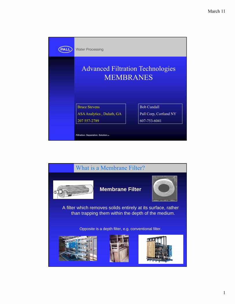
What is a Membrane Filter?
Membrane Filter
A filter which removes solids entirely at its surface, rather than trapping them within the depth of the medium.
Opposite is a depth filter, e.g. conventional filter.
March 11
2
Roles of Membranes in Treatment
• Remove Pathogens/Disinfection• Remove Suspended Solids • Remove Organics• Remove Organics• Remove Inorganics
– Desalination– Softening – Iron, Manganese– Arsenic
• Water Reuse
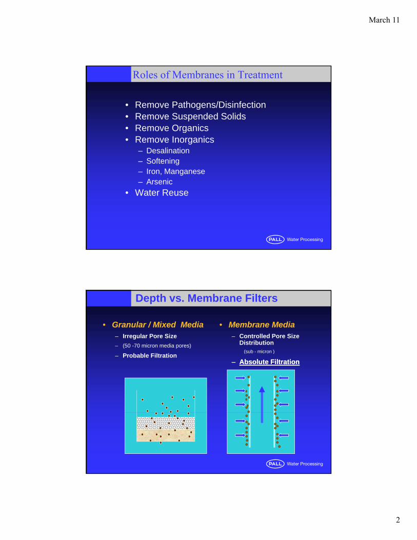
Depth vs. Membrane Filters
• Granular / Mixed Media– Irregular Pore Size
– (50 -70 micron media pores)
• Membrane Media– Controlled Pore Size
Distribution(sub micron )
– Probable Filtration(sub - micron )
–– Absolute FiltrationAbsolute Filtration
March 11
3
Microns
A Micron (µm) Is:
Also known as a "micrometer”Also known as a "micrometer” One millionth of a meterOne thousandth of a millimeter39 millionths of an inch (0.000039 in)
Will also see units of Daltons, or Molecular Weight Cutoff (MWCO)
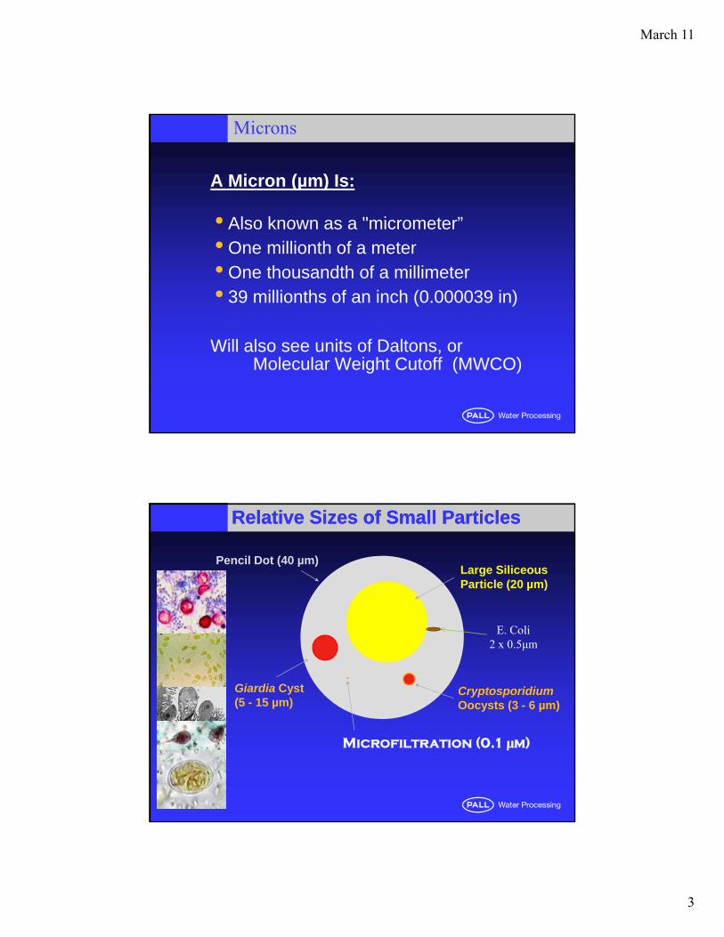
Relative Sizes of Small ParticlesRelative Sizes of Small Particles
Pencil Dot (40 µm)Large SiliceousParticle (20 µm)
CryptosporidiumOocysts (3 - 6 µm)
Giardia Cyst (5 - 15 µm)
E. Coli 2 x 0.5μm
Microfiltration (0.1 μm)
March 11
4
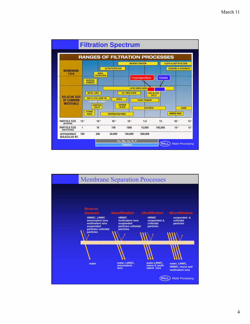
Filtration SpectrumFiltration Spectrum
GiardiaGiardiaCryptosporidiumCryptosporidium
OrganicsOrganicsFe, Mn, As, N, PFe, Mn, As, N, P
Membrane Separation Processes
Reverse
HMWC, LMWC monovalent ions multivalent ions suspended particles colloidal particles
HMWC multivalent ions suspended particles colloidal particles
HMWC suspended & colloidal particles
suspended & colloidal particles
Osmosis Nanofiltration Ultrafiltration Microfiltration
water water, LMWC, monovalent ions
water,LMWC,mono & multi-valent ions
water, LMWC, HMWC, mono and multivalent ions
March 11
5
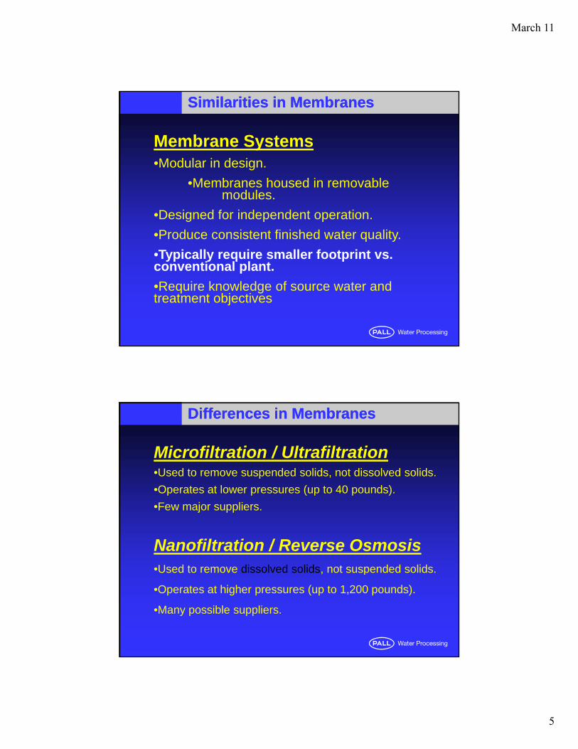
Membrane Systems•Modular in design.
Similarities in MembranesSimilarities in Membranes
•Membranes housed in removable modules.
•Designed for independent operation.
•Produce consistent finished water quality.
•Typically require smaller footprint vs. yp y q pconventional plant.
•Require knowledge of source water and treatment objectives
Microfiltration / Ultrafiltration•Used to remove suspended solids, not dissolved solids.
Operates at lo er press res ( p to 40 po nds)
Differences in MembranesDifferences in Membranes
•Operates at lower pressures (up to 40 pounds).
•Few major suppliers.
Nanofiltration / Reverse Osmosis•Used to remove dissolved solids, not suspended solids.Used to remove dissolved solids, not suspended solids.
•Operates at higher pressures (up to 1,200 pounds).
•Many possible suppliers.

March 11
6
Module Configuration
Flat SheetPleatedPl t & FPlate & FrameSpiral WoundCassette
Tubular andTubular andCeramic
Hollow Fiber
RO / NF Treatment Goals
•Reduce Total Dissolved Solids or Soften Water–Secondary Effluent
–Treated Industrial Wastewater (water reuse)
–Well Water / Brackish / High Brackish Water
–Sea Water
•Reduce Total Organic Carbon•Boiler Feed Water•High Purity Water (pharmaceutical, electronics)
March 11
7
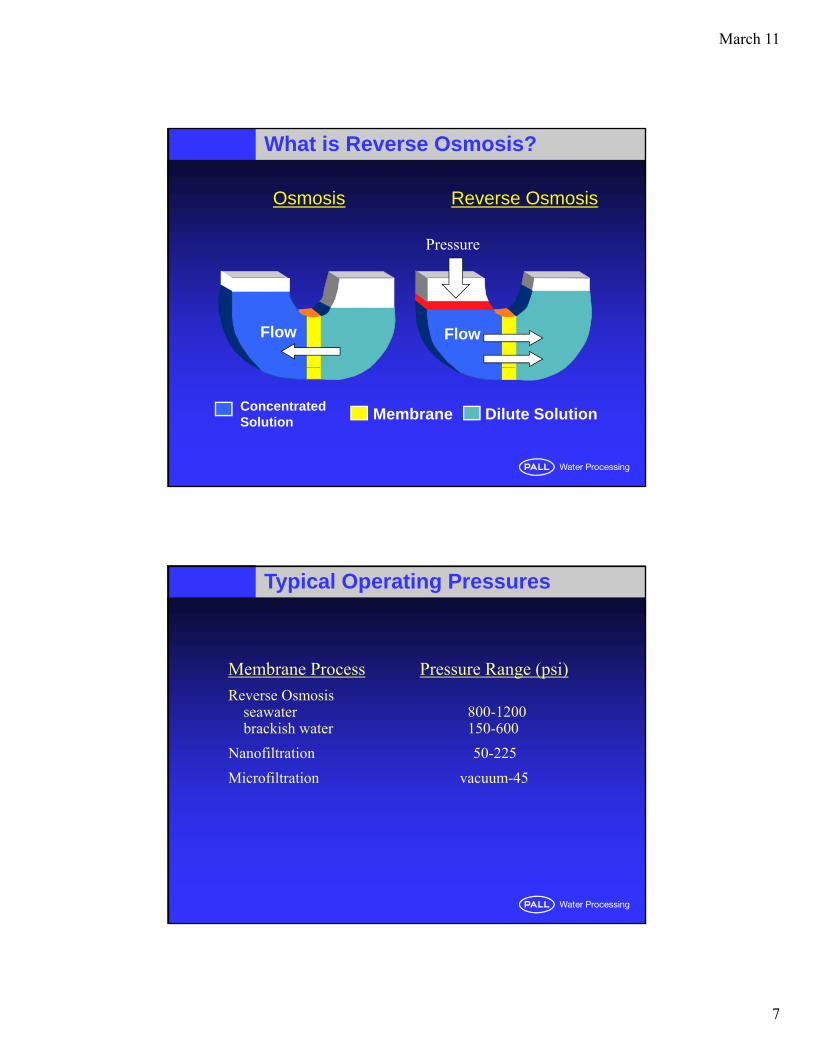
What is Reverse Osmosis?
Osmosis Reverse Osmosis
Pressure
Flow Flow
Pressure
Membrane Dilute SolutionConcentratedSolution
Typical Operating Pressures
Membrane Process Pressure Range (psi)
Reverse Osmosisseawater 800-1200brackish water 150-600
Nanofiltration 50-225
Microfiltration vacuum-45
March 11
8
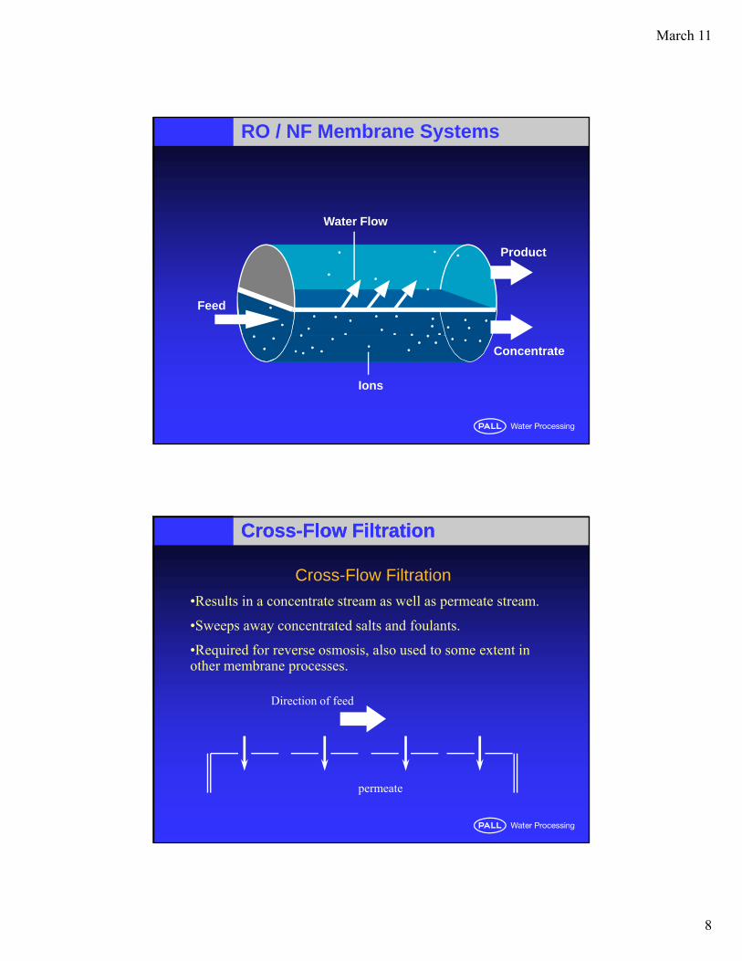
RO / NF Membrane Systems
Water Flow
Feed
Product
Ions
Concentrate
CrossCross--Flow FiltrationFlow Filtration
Cross-Flow Filtration
•Results in a concentrate stream as well as permeate stream.
•Sweeps away concentrated salts and foulants•Sweeps away concentrated salts and foulants.
•Required for reverse osmosis, also used to some extent in other membrane processes.
Direction of feed
permeate
March 11
9
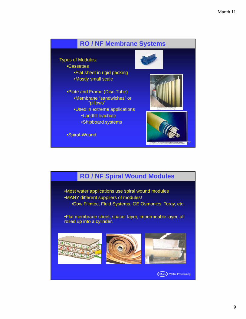
RO / NF Membrane Systems
Types of Modules:•Cassettes
•Flat sheet in rigid packingg g•Mostly small scale
•Plate and Frame (Disc-Tube)•Membrane “sandwiches” or
“pillows”•Used in extreme applicationspp
•Landfill leachate•Shipboard systems
•Spiral-Wound
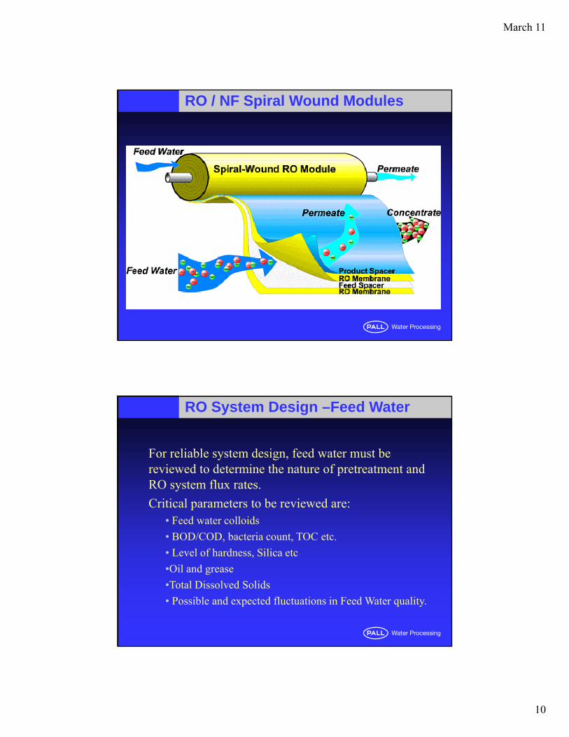
RO / NF Spiral Wound Modules
•Most water applications use spiral wound modules•MANY different suppliers of modules!
•Dow Filmtec, Fluid Systems, GE Osmonics, Toray, etc.
•Flat membrane sheet, spacer layer, impermeable layer, all rolled up into a cylinder.
March 11
10
RO / NF Spiral Wound Modules
RO System Design –Feed Water
For reliable system design, feed water must be reviewed to determine the nature of pretreatment and RO system flux rates.
Critical parameters to be reviewed are:• Feed water colloids
• BOD/COD, bacteria count, TOC etc.
• Level of hardness, Silica etc
•Oil and grease
•Total Dissolved Solids
• Possible and expected fluctuations in Feed Water quality.
March 11
11
RO System Design –Requirements
System Requirements review will determine:
•Wastewater disposal costsWastewater disposal costs
•Target finished water quality
•Power costs
•Footprint, labor costs, etc.
System design can be optimized based on the specific requirements.
RO System Design –Features
Typical Design features• Multistage RO based on recovery
•Multi-Pass RO based on product water quality
March 11
12
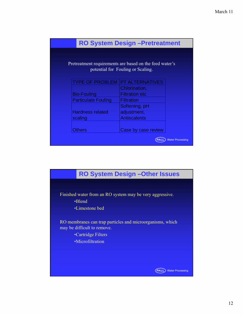
RO System Design –Pretreatment
Pretreatment requirements are based on the feed water’s potential for Fouling or Scaling.
TYPE OF PROBLEM PT ALTERNATIVES
Bio-Fouling Chlorination, Filtration etc
Particulate Fouling FiltrationSoftening, pH
Hardness related scaling
adjustment, Antiscalents
Others Case by case review
RO System Design –Other Issues
Finished water from an RO system may be very aggressive.
•Blend
•Limestone bed
RO membranes can trap particles and microorganisms, which may be difficult to remove.
•Cartridge Filters
Microfiltration•Microfiltration
March 11
13
RO System Design –Summary
RO systems can produce the quality and quantity of water desired.
Proper and adequate design guidelines should be followed to ensure trouble free operation.
B k h l d lBest known technology to reduce total dissolved solids cost effectively.
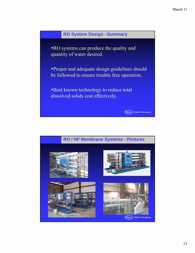
RO / NF Membrane Systems - Pictures
March 11
14
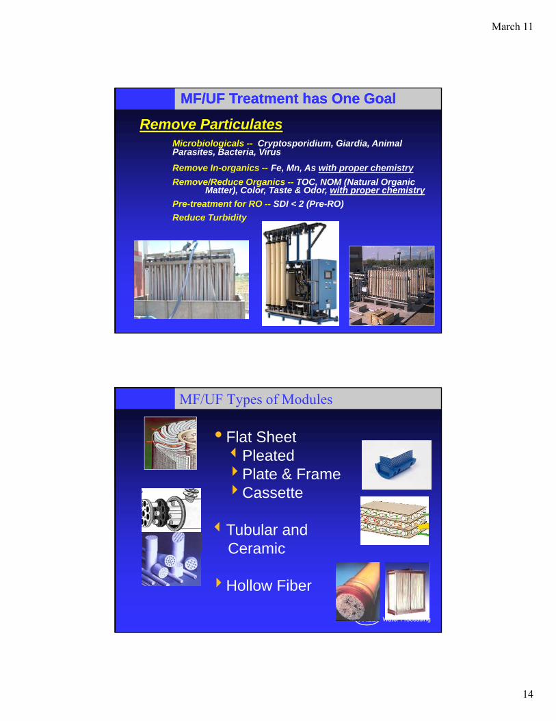
MF/UF Treatment has One GoalMF/UF Treatment has One Goal
Remove ParticulatesMicrobiologicals -- Cryptosporidium, Giardia, Animal Parasites, Bacteria, Virus
Remove In-organics -- Fe Mn As with proper chemistryRemove In organics Fe, Mn, As with proper chemistry
Remove/Reduce Organics -- TOC, NOM (Natural Organic Matter), Color, Taste & Odor, with proper chemistry
Pre-treatment for RO -- SDI < 2 (Pre-RO)
Reduce Turbidity
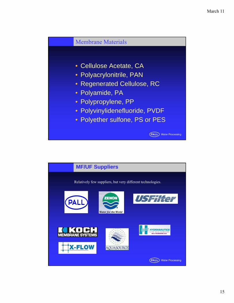
MF/UF Types of Modules
Flat SheetPleatedPl t & FPlate & FrameCassette
Tubular andCeramicCeramic
Hollow Fiber
March 11
15
Membrane Materials
• Cellulose Acetate, CA• Polyacrylonitrile, PAN• Regenerated Cellulose, RC• Polyamide, PA• Polypropylene, PP• Polyvinylidenefluoride, PVDF• Polyether sulfone, PS or PES
MF/UF SuppliersMF/UF Suppliers
Relatively few suppliers, but very different technologies.
March 11
16
Hollow-Fibers are most Common
•Very large surface area in small container.
•Surfaces easy to clean.
•Fibers can be manufactured with consistent pore size and porosity.
•Can be configured in a number of ways for different applications.
•Pressure vs Submerged•Pressure vs. Submerged
•Packing Density
•Outside-In vs. Inside-Out(Dead-End vs. Cross-flow)
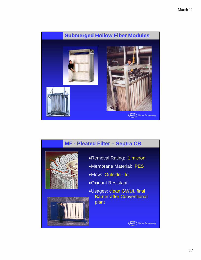
Pure Filtrate
Upper Potting
Membrane Module
Upper Bonded Section
Membrane Bundle Module Feed
A hollow
Module Housing
Lower Pottin
A hollow fiber
March 11
17
Submerged Hollow Fiber ModulesSubmerged Hollow Fiber Modules
MF - Pleated Filter – Septra CB
Removal Rating: 1 micron
Membrane Material: PES
Flow: Outside - In
Oxidant Resistant
Usages: clean GWUI, final Barrier after Conventional plant
March 11
18
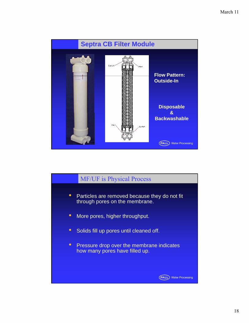
Septra CB Filter Module
Flow Pattern:
Disposable&
Flow Pattern:Outside-In
& Backwashable
MF/UF is Physical Process
Particles are removed because they do not fit through pores on the membrane.
More pores, higher throughput.
Solids fill up pores until cleaned off.
Pressure drop over the membrane indicatesPressure drop over the membrane indicates how many pores have filled up.
March 11
19
MF/UF is Physical Process
Particles are removed because they do not fit through pores on the membrane. (Removal Rating)
(Fl ) More pores, higher throughput. (Flux)
Solids fill up pores (Fouling, Blinding) until cleaned off. (Backwash, Clean-in-Place cleaning)
Pressure drop over the membrane indicates how many pores have filled up (Transmembrane Pressurepores have filled up. (Transmembrane Pressure, or TMP)
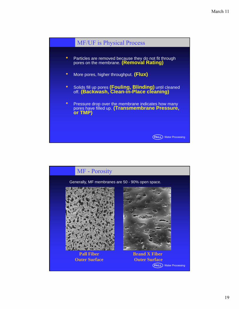
MF - Porosity
Generally, MF membranes are 50 - 90% open space.
Pall Fiber Outer Surface
Brand X FiberOuter Surface
March 11
20
Definitions of Removal RatingsDefinitions of Removal Ratings
Absolute Rating
The diameter of the largest hard spherical particle that will pass through a filter under specified test conditions. This is an indication of the largest opening in the filter medium.opening in the filter medium.
Nominal Rating
A value indicating a particulate size range which the filter manufacturerclaims the filter removes a certain percentage of.
Nominal ratings vary from manufacturer to manufacturer and should not be used to compare filters.p
Molecular Weight Cut Off (MWCO)
Nominal rating system for ultrafiltration and nanofiltration membranes. MWCO is defined as the molecular weight of solute that the membrane can retain 90% of.
Due to a lack of any industry standards or common
d fi i i h h ld
Microfiltration vs. UltrafiltrationMicrofiltration vs. Ultrafiltration
definitions, these terms should not be used to compare products from different
manufacturers!
March 11
21
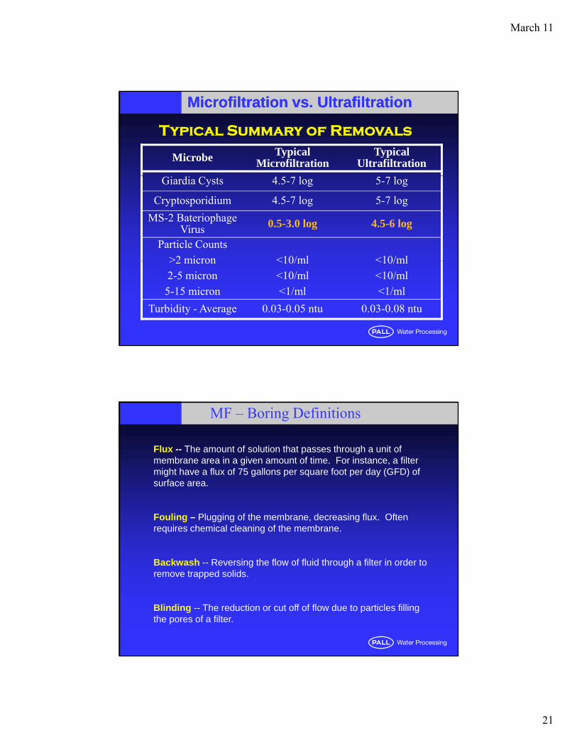
Microfiltration vs. UltrafiltrationMicrofiltration vs. Ultrafiltration
Typical Summary of Removals
Microbe Typical Microfiltration
Typical Ultrafiltration
Giardia Cysts 4.5-7 log 5-7 log
Cryptosporidium 4.5-7 log 5-7 log
MS-2 Bateriophage Virus 0.5-3.0 log 4.5-6 log
Particle Counts>2 micron <10/ml <10/ml>2 micron2-5 micron5-15 micron
<10/ml<10/ml<1/ml
<10/ml<10/ml<1/ml
Turbidity - Average 0.03-0.05 ntu 0.03-0.08 ntu
Flux -- The amount of solution that passes through a unit of membrane area in a given amount of time. For instance, a filter might have a flux of 75 gallons per square foot per day (GFD) of surface area.
MF – Boring Definitions
Fouling – Plugging of the membrane, decreasing flux. Often requires chemical cleaning of the membrane.
Backwash -- Reversing the flow of fluid through a filter in order to t d lidremove trapped solids.
Blinding -- The reduction or cut off of flow due to particles filling the pores of a filter.
March 11
22
Transmembrane Pressure (TMP) -- The force which drives liquid flow through a cross-flow membrane. The upstream side (the side of the membrane the solution enters by) of a TFF system is under a higher pressure than the downstream side. This pressure
MF – More Boring Definitions
g p pdifference forces liquid through the membrane.
Differential Pressure (DP) -- is the difference between the pressure in the system before the fluid reaches the filter (upstream pressure) and the system pressure after the fluid flows through the filter (downstream pressure). As the filter begins to l diff ti l iclog, differential pressure increases.
MF - Traditional CIP Practices
• Full vigorous CIP removes all foulants and completely restores permeability
CIP target interval is 21 30 days• CIP target interval is 21-30 days
• CIP interval is selected based on a pragmatic balance between several factors:a. cost of chemicalsb do ntimeb. downtimec. labor or manpowerd. membrane longevity
March 11
23
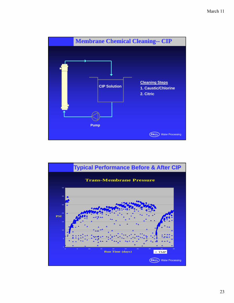
Membrane Chemical CleaningMembrane Chemical Cleaning---- CIPCIP
CIP SolutionCleaning Steps
1. Caustic/Chlorine
2. Citric
Pump
Typical Performance Before & After CIPTypical Performance Before & After CIP
Trans-Membrane Pressure
30
35
10
15
20
25
PSI
0
5
0 5 10 15 20 25 30 35 40 45
Run Time (days) TMP

March 11
24
MF System Design –Feed Water
For reliable system design, feed water must be reviewed to determine the nature of pretreatment (if any) and their impact on MF system flux rates.
Critical parameters to be reviewed are:• BOD/COD, bacteria count, TOC etc.
• Presence of metals.
•Total Suspended Solids.
• Possible and expected fluctuations in Feed Water quality.
•Utility of existing equipment.
MF System Design –Requirements
System Requirements review will determine:
•Wastewater disposal costsWastewater disposal costs
•Desired pretreatment, if any
•Power costs
•Footprint, labor costs, etc.
System design can be optimized based on the specific requirements.

March 11
25
San Patricio MWD – 8 MGD System
Chandler, AZ - 1.75 mgd
March 11
26
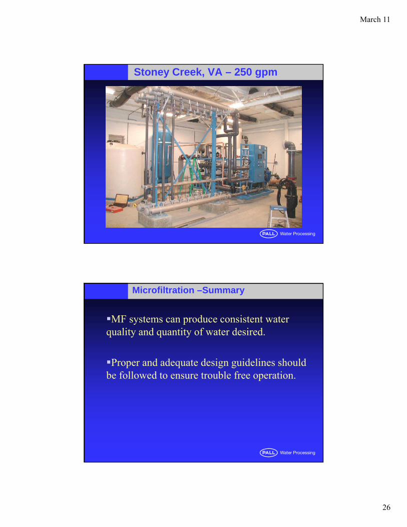
Stoney Creek, VA – 250 gpm
Microfiltration –Summary
MF systems can produce consistent water quality and quantity of water desired.
Proper and adequate design guidelines should be followed to ensure trouble free operation.
March 11
27
Conclusions
A well-designed membrane system can remove contaminants from a wide variety of source
twaters.
Membranes can provide an economical method of meeting water treatment regulations.
Recommended


![[XLS] · Web viewXIII-91 O-AG-06-100011 W 0-AG-06-100011(W) O-AG-06-100011(W) 394 MA 5940 TR 120506-007 TR120506-011 TR120506-069 120506-007 TR120506-009 5760 TR 12 05 070 10 TR120507010](https://img.pdfslide.us/doc/110x75/5ae3d8767f8b9a5d648e7b96/xls-viewxiii-91-o-ag-06-100011-w-0-ag-06-100011w-o-ag-06-100011w-394-ma-5940.jpg)