http://www.pisco.co.jphttp://www.pisco.co.jp
576
Mechanical V
alveTUBE
VALVE
MAKE-TO-ORDERPRODUCTS
Push-In Fitting Type Mechanical ValveMechanical Valve Series
●Stable Operation by Spool Valve.
●Push-type Open/Close Valve.
●Selection of Two- or Three-Directional Control Valve.
●Panel Mount Type with Rotatable Fitting to All Directions. Easy Tube Insertion.

Valve Series
577
Mechanical V
alve
Mechanical Valve Series
Change V
alveS
hut-off Valve
VALV
ECO
NTRO
LLER
FITT
ING ■ Model Designation (Example)
MV M 6
② Tube dia.Code 4 6Size ø4 ø6
Mechanical Valve ⑥Exhaust system①
Type
R J
⑥
⑤Operating method②
Tube dia.
④ Valve type No code:Normally Closed (Release ring color: Black) A:Normally Open (Release ring color: Light-gray) ※ Only Normally Closed type is available for MVP and MVU.
3 A
④Valve type③
Number of ports
Code Type Code Type Code Type Code Type
M Micro Switch Type P Panel Mount Type U Air Switch Type F Foot Switch Type
① Type
③ Number of portsCode 2 3
Number of ports 2 3
⑤ Operating method No code:Pin R:Roller lever ※ Only Pin type is available for MVU
⑥ Exhaust system (Three-Directional Control Valve only) No code:Open-Air Exhaust through Silencer J:Push-in fitting tube exhaust
http://www.pisco.co.jphttp://www.pisco.co.jp
578
Mechanical V
alveTUBE
VALVE
MAKE-TO-ORDERPRODUCTS
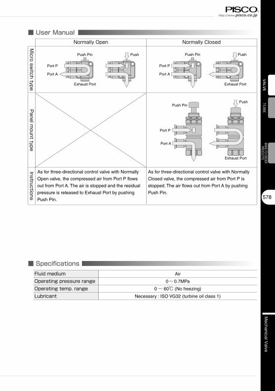
■ User ManualNormally Open Normally Closed
Micro sw
itch type
Push Pin
Exhaust Port
Port P
Port A
Push Push Pin
Exhaust Port
Port P
Port A
Push
Panel m
ount type
Push Pin
Exhaust Port
Port P
Port A
Push
Instructions
As for three-directional control valve with Normally
Open valve, the compressed air from Port P flows
out from Port A. The air is stopped and the residual
pressure is released to Exhaust Port by pushing
Push Pin.
As for three-directional control valve with Normally
Closed valve, the compressed air from Port P is
stopped. The air flows out from Port A by pushing
Push Pin.
■ Specifications Fluid medium Air
Operating pressure range 0~0.7MPa
Operating temp. range 0~ 60℃ (No freezing)
Lubricant Necessary : ISO VG32 (turbine oil class 1)

Valve Series
579
Mechanical V
alve
Mechanical Valve Series
Change V
alveS
hut-off Valve
VALV
ECO
NTRO
LLER
FITT
ING ■ Construction (Micro Switch Type, Pin Type : MVM)
Elastic sleeve (NBR)
Tube
Release ring (POM)
Lock-claws (Stainless steel)
Flat O-ring (NBR)
Resin body (PBT)
Spring holder (Nickel-plated brass)
Guide ring (Nickel-plated brass)
Push pin (POM)
Tube guide (Nickel-plated brass)
Detailed Safety InstructionsBefore using PISCO products, be sure to read “Safety Instructions” and “Safety Instruction Manual” on page
23 to 27 and “Common Safety Instructions for Valves” on page 549 to 550.
Warning1. Do not apply excessive load beyond the stroke limits on the push pin and the roller. It may cause
damage to Mechanical Valve.
2. Do not use the valve for the applications such as cam or dog which are operated with a rapid starting.
Impacts can cause damage to Mechanical Valve.
3. Do not use machine to control Air Switch and Foot Switch type. It may cause damage to Mechanical
Valve.
4. When Mechanical Valve is used on the application which requires high reliability, make sure the valve
performs properly before the operation. There is a possibility to cause damage to the system due to a
malfunction of the valve.
5. Resin body is rotatable, but do not swing or rotate it by force or continuously. It may cause damage to the
products and a fluid leakage.
6. Keep Mechanical Valve away from water / oil drops or dusts. These may cause malfunction, since the
valve is not drip / dust proof.
←Port P
→Port A
↓EX port
Seal ring (Nickel-plated brass)
Metal pipe in fixing hole (Nickel-plated brass)
Spool (Nickel-plated brass)
※ Release ring color / Normally closed valve type: Black, Normally open valve type: Light-gray
Caution1. Contact PISCO in case of using Mechanical Valve in applications with frequent use.
2. Confirm the number of ports and valve type by the marking on the valve body.
3. Effective area of Micro Switch and Foot Switch type may change by the stroke range. Insufficient stroke
range can cause a lack of air flow rate.
4. Make sure to push the push pin of Air Switch and Foot Switch or the upper lid of Foot Switch completely
until it stops. Incomplete switchover can cause a poor path connection or low flow rate.
Spring (Piano wire)

http://www.pisco.co.jphttp://www.pisco.co.jp
580
Mechanical V
alveTUBE
VALVE
MAKE-TO-ORDERPRODUCTS
Type Page Number of portsTube O.D.(mm)
4 6MVM Open-Air Exhaust Pin Type P.582 2 ● ●
3 ● ●MVM Pipe Exhaust Pin Type P.582 3 ● ●
■ Standard Size ListMicro Switch Type
Type Page Number of portsTube O.D.(mm)
4 6MVM Open-Air Exhaust Roller Type P.583 2 ● ●
3 ● ●MVM Pipe Exhaust Roller Type P.583 3 ● ●
Type Page Number of portsTube O.D.(mm)
4 6MVP Open-Air Exhaust Pin Type P.584 2 ● ●
3 ● ●MVP Pipe Exhaust Pin Type P.584 3 ● ●
Panel Mount Type
Type Page Number of portsTube O.D.(mm)
4 6MVP Open-Air Exhaust Roller Type P.585 2 ● ●
3 ● ●MVP Pipe Exhaust Roller Type P.585 3 ● ●
Type Page Number of portsTube O.D.(mm)
4 6MVU Air Switch P.586 2 ● ●
3 ● ●
The Others
Type Page Number of portsTube O.D.(mm)
4 6MVF Foot Switch P.586 2 ● ●
3 ● ●

Valve Series
581
Mechanical V
alve
Mechanical Valve Series
Change V
alveS
hut-off Valve
VALV
ECO
NTRO
LLER
FITT
ING
■ Applicable Tube and Related ProductsPolyurethane Tube………P.596Nylon Tube…………P.608
■ How to insert and disconnect1. How to insert and disconnect tubes① Tube insertion
Insert a tube into Push-In Fitting up to the tube end. Lock-claws bite the tube
and fix it automatically, then the elastic sleeve seals around the tube.
Refer to “2. Instructions for Tube Insertion” under “Common Safety Instructions
for Fittings” .
② Tube disconnection
The tube is disconnected by pushing release-ring to release Lock-claws.
Make sure to stop air supply before the tube disconnection.
2. How to tighten thread① Tightening thread
Use a spanner to tighten a hexagonal-column of Panel Mount Type.
The range of tightening torque is between 2.5 and 3.5Nm.
② How to fix valve body
In order to fix the valve body of Micro Switch Type and Air Switch Type, use
the fixing holes on the body to tighten with M3 screw. Refer to the dimensional
drawings of the hole pitch.

http://www.pisco.co.jphttp://www.pisco.co.jp
582
Mechanical V
alveTU
BE
VALVE
MAKE-TO-ORDERPRODUCTS
CAD data is available at PISCO website.CAD
MVM
Unit:mm
Model codeTube O.D.
øDB1
B2 L1 L2 øP Tube end C
J FWeight
(g)Effective area(mm2)
CADfile namemax. min.
MVM 4□4 23.5 21.1 33 17 7.2 8 11 8 10.6 10 3
CHM-001
MVM 4□AMVM 6□
6 30.7 27.1 33.4 22 7.2 10.5 11.6 10.5 15.6 12 7MVM 6□A
※ □ in Model code / Replaced with “2” for Two-directional control valve, “3” for Three-directional control valve.
ø10
J
L1
B26.8
14.33.220.7 2-ø3.3
11
B1 F
L2
2-ø
D2-
øP
2-C
EXH
Port P
Port A
CADMicro Switch Open-Air Exhaust Pin Type
■ Micro Switch Open-Air Exhaust Pin Type
A PA P
RA P
A P
R
Symbol of Pin Type
Normally Closed2 ports
Normally Open Normally Closed3 ports
Normally Open
MVM
Unit:mm
Model codeTube O.D.
øDB1
B2 L1 L2 øP Tube end C
J1 J2 E FWeight
(g)Effective area(mm2)
CADfile namemax. min.
MVM 43-J4 26.4 24 33 17 7.2 8 11 8 10.4 15 10.6 11 3
CHM-001
MVM 43A-JMVM 63-J
6 34.8 31.2 33.4 22 7.2 10.5 11.6 10.5 13.9 16.4 15.614
7MVM 63A-J 15
J1J2
L1
B2
14.33.220.7
2-ø3.3
11
B1 F
L2
3-ø
D3-
øP
3-CE6.8
Port P
Port A
Port R
CADMicro Switch Tube Exhaust Pin Type
A P
R
A P
R
Symbol of Pin Type
Normally Closed3 ports
Normally Open
■ Push pin stroke dimension / Micro Switch Pin Type
S1
S2
S4
S3
S5
Unit:mm
Tube O.D.øD
Free stroke rangeS1
Operating stroke rangeS2
Sub strokeS3
Recommended strokeS4
Limit strokeS5
4 1 1 0.4 2 2.4
6 1.6 1.6 0.4 3.2 3.6

Valve Series
583
Mechanical V
alve
Mechanical Valve Series
Change V
alveS
hut-off Valve
VALV
ECO
NTRO
LLER
FITT
ING
CAD data is available at PISCO website.CAD
MVM
Unit:mm
Model codeTube O.D.
øDB1
B2 L1L2
øP Tube end C
J FWeight
(g)Effective area(mm2)
CADfile namemax. min. max. min.
MVM 4□ -R4 34.7 31.1 33 17 18.4 14.8 8 11 8 10.6 12 3
CHM-001
MVM 4□A-RMVM 6□ -R
6 41.9 37 33.4 22 19.6 14.7 10.5 11.6 10.5 15.6 15 7MVM 6□A-R
※ □ in Model code / Replaced with “2” for Two-directional control valve, “3” for Three-directional control valve.
ø10
J
L1
B2
14.33.220.7 2-ø3.3
11
7B
1F
L2 2-ø
D2-
øP
2-C
ø9
Port P
Port AEXH
CADMicro Switch Open-Air Exhaust Roller Type
■ Micro Switch Open-Air Exhaust Roller Type
A PA P
RA P
A P
R
Symbol of Roller Type
Normally Closed2 ports
Normally Open Normally Closed3 ports
Normally Open
MVM
Unit:mm
Model codeTube O.D.
øDB1
B2 L1L2
øP Tube end C
J1 J2 E FWeight(g)
Effective area(mm2)
CADfile namemax. min. max. min.
MVM 43-RJ4 37.6 34 33 17 18.4 14.8 8 11 8 10.4 15 10.6 13 3
CHM-001
MVM 43A-RJMVM 63-RJ
6 46 41.1 33.4 22 19.6 14.7 10.5 11.6 10.5 13.9 16.4 15.6 17 7MVM 63A-RJ
J1J2
L1
B2
14.33.220.7
2-ø3.3
11
B1
FL2 3-ø
D3-
øP
3-CE
7ø9
Port P
Port A
Port R
CADMicro Switch Tube Exhaust Roller Type
A P
R
A P
R
Symbol of Roller Type
Normally Closed3 ports
Normally Open
■ Push pin stroke dimension / Micro Switch Roller Type
S5
S1
S2
S4
S3
Unit:mm
Tube O.D.øD
Free stroke rangeS1
Operating stroke rangeS2
Sub strokeS3
Recommended strokeS4
Limit strokeS5
4 1.5 1.7 0.4 3.2 3.6
6 1.7 2.5 0.4 4.5 4.9
compliant
compliant

http://www.pisco.co.jphttp://www.pisco.co.jp
584
Mechanical V
alveTU
BE
VALVE
MAKE-TO-ORDERPRODUCTS
CAD data is available at PISCO website.CAD
MVP
Unit:mm
Model codeTube O.D.
øDB
L øP Tube end C
EWeight
(g)Effective area
(mm2)CAD
file namemax. min.MVP 42
448.5 44.5 33
8 11 17.730
3CHM-002
MVP 43 48 44 32.5 29
MVP 626
48.5 44.5 3310.5 11.6 18.3
325
MVP 63 48 44 32.5 31
2-øD2-øP
BL 6
39.512
2-C
ø9
E
M10×0.75
3-Hex.14
Port PPort A
EXH
CADPanel Mount Open-Air Exhaust Pin Type
■ Panel Mount Open-Air Exhaust Pin Type
A PA P
R
Symbol of Pin Type
Normally Closed2 ports
Normally Open3 ports
MVP
Unit:mm
Model codeTube O.D.
øDB
øP Tube end C
EWeight
(g)Effective area
(mm2)CAD
file namemax. min.MVP 43-J 4 57 53.4 8 11 17.7 32 3
CHM-002MVP 63-J 6 57 53.4 10.5 11.6 18.3 34 5
3-øD3-øP
B41.5 6
39.52-12
3-C
ø9
E
M10×0.75
3-Hex.14
Port PPort A
Port R
CADPanel Mount Tube Exhaust Pin Type
A P
R
Symbol of Pin Type
Normally Closed3 ports
■ Push pin stroke dimension / Panel Mount Pin Type
S5
S3
S4
S2
S1
Unit:mm
Tube O.D.øD
Free stroke rangeS1
Operating stroke rangeS2
Sub strokeS3
Recommended strokeS4
Limit strokeS5
4 1.8 1.8 0.4 3.6 4
6 1.8 1.8 0.4 3.6 4
compliant
compliant

Valve Series
585
Mechanical V
alve
Mechanical Valve Series
Change V
alveS
hut-off Valve
VALV
ECO
NTRO
LLER
FITT
ING
CAD data is available at PISCO website.CAD
■ Panel Mount Open-Air Exhaust Roller Type
■ Push pin stroke dimension / Panel Mount Roller Type
S5
S3
2.5
S4
S2
S1 Unit:mm
Tube O.D.øD
Free stroke rangeS1
Operating stroke rangeS2
Sub strokeS3
Recommended strokeS4
Limit strokeS5
4 1.8 2.2 0.4 4 4.4
6 1.8 2.2 0.4 4 4.4
※ This stroke dimension includes a board of 2.5mm thick. The stroke changes by a
thickness of board.
MVP
Unit:mm
Model codeTube O.D.
øDB
L øP Tube end C
EWeight
(g)Effective area
(mm2)CAD
file namemax. min.MVP 42-R
457.4 53 33
8 11 17.734
3CHM-003
MVP 43-R 56.9 52.5 32.5 33
MVP 62-R6
57.4 53 3310.5 11.6 18.3
355
MVP 63-R 56.9 52.5 32.5 34
2-øD
ø9
2-øP
BL
62.5
9.5122-
CE
19.6
M10×0.75
3-Hex.14
Port PPort A
EXH
CADPanel Mount Open-Air Exhaust Roller Type
A PA P
R
Symbol of Roller Type
Normally Closed2 ports
Normally Closed3 ports
MVP
Unit:mm
Model codeTube O.D.
øDB
øP Tube end C
EWeight
(g)Effective area
(mm2)CAD
file namemax. min.MVP 43-RJ 4 65.9 61.5 8 11 17.7 36 3
CHM-003MVP 63-RJ 6 65.9 61.5 10.5 11.6 18.3 38 5
ø9
3-øD3-øP
B41.5
62.5
9.52-12
3-C
E
19.6
M10×0.75
3-Hex.14
Port PPort A
Port R
CADPanel Mount Tube Exhaust Roller Type
A P
R
Symbol of Roller Type
Normally Closed3 ports
compliant
compliant

http://www.pisco.co.jphttp://www.pisco.co.jp
586
Mechanical V
alveTU
BE
VALVE
MAKE-TO-ORDERPRODUCTS
CAD data is available at PISCO website.CAD
■ Air Switch
MVU
Unit:mm
Model codeTube O.D.
øD BTube end
CWeight
(g)Effective area
(mm2)CAD
file name
MVU 424 28.6 10.9
223
CHM-004MVU 43 23
MVU 626 31.1 11.7
225
MVU 63 23
※ Body color: Light-gray / Release ring: Black
2-øD
35.4
2.5(Stroke)
8
22
B10
222-
Cø
92-13
2-ø3.4□22 CADAir Switch
A PA P
R
Symbol of Push Button Type2 ports 3 ports
MVF
Model codeTube O.D.
øDWeight
(g)Effective area(mm2)
CADfile name
MVF 4□□ 4 172.5 3 CHM-004MVF 6□□ 6 174.5 7
80
526
96
120
610
14.5
14.5
51.4
4-ø5.5
CADFoot Switch
A PA P
RA P
A P
R
Symbol of Pedal Type
Normally Closed2 ports
Normally Open Normally Closed3 ports
Normally Open
■ Foot Switch
※ Left □ in Model code / Replaced with “2” for Two-directional control
valve, “3” for Three-directional control valve.
Right □ in Model code / Replaced with “A” for Normally Open, or
remained blank for Normally Closed
※ Micro Switch Pin Type(MVM4□ / MVM4□A) is used in MVF4□□ .
※ Micro Switch Pin Type(MVM6□ / MVM6□A) is used in MVF6□□ .
compliant
compliant

Valve Series
587
Mechanical V
alve
Mechanical Valve Series
Change V
alveS
hut-off Valve
VALV
ECO
NTRO
LLER
FITT
ING

23
Safety Instructions
SAFETY Instructions
Warning
This safety instructions aim to prevent personal injury and damage to properties by requiring proper use of PISCO products. Be certain to follow ISO 4414 and JIS B 8370
ISO 4414:Pneumatic fluid power…Recomendations for the application of equipment to transmission and control systems.
JIS B 8370:General rules and safety requirements for systems and their components.This safety instructions is classified into “Danger”, “Warning” and “Caution” depending on the degree of danger or damages caused by improper use of PISCO products.
1. Selection of pneumatic products① A user who is a pneumatic system designer or has sufficient experience
and technical expertise should select PISCO products.② Due to wide variety of operating conditions and applications for PISCO
products, carry out the analysis and evaluation on PISCO products. The pneumatic system designer is solely responsible for assuring that the user's requirements are met and that the application presents no health or safety hazards. All designers are required to fully understand the specifications of PISCO products and constitute all systems based on the latest catalog or information, considering any malfunctions.
2. Handle the pneumatic equipment with enough knowledge and experience① Improper use of compressed air is dangerous. Assembly, operation
and maintenance of machines using pneumatic equipment should be conducted by a person with enough knowledge and experience.
3. Do not operate machine / equipment or remove pneumatic equipment until safety is confirmed.① Make sure that preventive measures against falling work-pieces or
sudden movements of machine are completed before inspection or maintenance of these machine.
② Make sure the above preventive measures are completed. A compressed air supply and the power supply to the machine must be off, and also the compressed air in the systems must be exhausted.
③ Restart the machines with care after ensuring to take all preventive measures against sudden movements.
Danger Hazardous conditions. It can cause death or serious personal injury.
Warning Hazardous conditions depending on usages. Improper use of PISCO products can cause death or serious personal injury.
Caution Hazardous conditions depending on usages. Improper use of PISCO products can cause personal injury or damages to properties.
※ . This safety instructions are subject to change without notice.

http://www.pisco.co.jphttp://www.pisco.co.jp
24
Disclaimer1. PISCO does not take any responsibility for any incidental or indirect
loss, such as production line stop, interruption of business, loss of benefits, personal injury, etc., caused by any failure on use or application of PISCO products.
2. PISCO does not take any responsibility for any loss caused by natural disasters, fires not related to PISCO products, acts by third parties, and intentional or accidental damages of PISCO products due to incorrect usage.
3. PISCO does not take any responsibility for any loss caused by improper usage of PISCO products such as exceeding the specification limit or not following the usage the published instructions and catalog allow.
4. PISCO does not take any responsibility for any loss caused by remodeling of PISCO products, or by combinational use with non-PISCO products and other software systems.
5. The damages caused by the defect of Pisco products shall be covered but limited to the full amount of the PISCO products paid by the customer.
25
Safety Instructions
SAFETY INSTRUCTION MANUAL
Danger1. Do not use PISCO products for the following applications.
① Equipment used for maintaining / handling human life and body.② Equipment used for moving / transporting human.③ Equipment specifically used for safety purposes.
Warning1. Do not use PISCO products under the following conditions.
① Beyond the specifications or conditions stated in the catalog, or the instructions.② Under the direct sunlight or outdoors.③ Excessive vibrations and impacts.④ Exposure / adhere to corrosive gas, inflammable gas, chemicals, seawater, water and vapor. *
* Some products can be used under the condition above(④), refer to the details of specification and condition of each product.
2. Do not disassemble or modify PISCO products, which affect the performance, function, and basic structure of the product.
3. Turn off the power supply, stop the air supply to PISCO products, and make sure there is no residual air pressure in the pipes before maintenance and inspection.
4. Do not touch the release-ring of push-in fitting when there is a working pressure. The lock may be released by the physical contact, and tube may fly out or slip out.
5. Frequent switchover of compressed air may generate heat, and there is a risk of causing burn injury.
6. Avoid any load on PISCO products, such as a tensile strength, twisting and bending. Otherwise, there is a risk of causing damage to the products.
7. As for applications where threads or tubes swing / rotate, use Rotary Joints, High Rotary Joints or Multi-Circuit Rotary Block only. The other PISCO products can be damaged in these applications.
8. Use only Die Temperature Control Fitting Series, Tube Fitting Stainless SUS316 Series, Tube Fitting Stainless SUS316 Compression Fitting Series or Tube Fitting Brass Series under the condition of over 60℃ (140°F) water or thermal oil. Other PISCO products can be damaged by heat and hydrolysis under the condition above.
9. As for the condition required to dissipate static electricity or provide an antistatic performance, use EG series fitting and antistatic products only, and do not use other PISCO products. There is a risk that static electricity can cause system defects or failures.
10. Use only Fittings with a characteristic of spatter-proof such as Anti-spatter or Brass series in a place where flame and weld spatter is produced. There is a risk of causing fire by sparks.
11. Turn off the power supply to PISCO products, and make sure there is no residual air pressure in the pipes and equipment before maintenance. Follow the instructions below in order to ensure safety.① Make sure the safety of all systems related to PISCO products before maintenance.② Restart of operation after maintenance shall be proceeded with care after
ensuring safety of the system by preventive measures against unexpected movements of machines and devices where pneumatic equipment is used.
③ Keep enough space for maintenance when designing a circuit.12. Take safety measures such as providing a protection cover if there is a
risk of causing damages or fires on machine / facilities by a fluid leakage.
PISCO products are designed and manufactured for use in general industrial machines. Be sure to read and follow the instructions below.

http://www.pisco.co.jphttp://www.pisco.co.jp
26
Caution1. Remove dusts or drain before piping. They may get into the peripheral
machine / facilities and cause malfunction.2. When inserting an ultra-soft tube into push-in fitting, make sure to place
an Insert Ring into the tube edge. There is a risk of causing the escape of tube and a fluid leakage without using an Insert Ring.
3. The product incorporating NBR as seal rubber material has a risk of malfunction caused by ozone crack. Ozone exists in high concentrations in static elimination air, clean-room, and near the high-voltage motors, etc. As a countermeasure, material change from NBR to HNBR or FKM is necessary. Consult with PISCO for more information.
4. Special option “Oil-free” products may cause a very small amount of a fluid leakage. When a fluid medium is liquid or the products are required to be used in harsh environments, contact us for further information.
5. In case of using non-PISCO brand tubes, make sure the tolerance of the outer tube diameter is within the limits of Table 1.
●Table 1. Tube O.D. Tolerancemm size Nylon tube Polyurethane tube inch size Nylon tube Polyurethane tubeø1.8mm ─ ±0.05mm ø1/8 ±0.1mm ±0.15mmø3mm ─ ±0.15mm ø5/32 ±0.1mm ±0.15mmø4mm ±0.1mm ±0.15mm ø3/16 ±0.1mm ±0.15mmø6mm ±0.1mm ±0.15mm ø1/4 ±0.1mm ±0.15mmø8mm ±0.1mm ±0.15mm ø5/16 ±0.1mm ±0.15mmø10mm ±0.1mm ±0.15mm ø3/8 ±0.1mm ±0.15mmø12mm ±0.1mm ±0.15mm ø1/2 ±0.1mm ±0.15mmø16mm ±0.1mm ±0.15mm ø5/8 ±0.1mm ±0.15mm
6. Instructions for Tube Insertion① Make sure that the cut end surface of the tube is at right angle without
a scratch on the surface and deformations.② When inserting a tube, the tube needs to be inserted fully into the push-
in fitting until the tubing edge touches the tube end of the fitting as shown in the figure below. Otherwise, there is a risk of leakage.
Tube end
Sealing
Tube is not fully inserted up to tube end.
③ After inserting the tube, make sure it is inserted properly and not to be disconnected by pulling it moderately.
※. When inserting tubes, Lock-claws may be hardly visible in the hole, observed from the front face of the release-ring. But it does not mean the tube will surely escape. Major causes of the tube escape are the followings; ①Shear drop of the lock-claws edge②The problem of tube diameter (usually small)Therefore, follow the above instructions from ① to ③, even lock-claws is hardly visible.

27
7. Instructions for Tube Disconnection① Make sure there is no air pressure inside of the tube, before disconnecting it.② Push the release-ring of the push-in fitting evenly and deeply enough to
pull out the tube toward oneself. By insufficient pushing of the release-ring, the tube may not be pulled out or damaged by scratch, and tube shavings may remain inside of the fitting, which may cause the leakage later.
8. Instructions for Installing a fitting① When installing a fitting, use proper tools to tighten a hexagonal-column
or an inner hexagonal socket. When inserting a hex key into the inner hexagonal socket of the fitting, be careful so that the tool does not touch lock-claws. The deformation of lock-claws may result in a poor performance of systems or an escape of the tube.
② Refer to Table 2 which shows the recommended tightening torque. Do not exceed these limits to tighten a thread. Excessive tightening may break the thread part or deform the gasket and cause a fluid leakage. Tightening thread with tightening torque lower than these limits may cause a loosened thread or a fluid leakage.
③ Adjust the tube direction while tightening thread within these limits, since some PISCO products are not rotatable after the installation.
●Table 2: Recommended tightening torque / Sealock color / Gasket materialsThread type Thread size Tightening torque Sealock color Gasket materials
Metric thread
M3×0.5 0.7N·m
─
SUS304NBR
M5×0.8 1.0 ~ 1.5N·mM6×1 2 ~ 2.7N·m
M3×0.5 0.5 ~ 0.6N·m
POMM5×0.8 1 ~ 1.5N·mM6×0.75 0.8 ~ 1N·mM8×0.75 1 ~ 2N·m
Taper pipe thread
R1/8 7 ~ 9N·m
White ─R1/4 12 ~ 14N·mR3/8 22 ~ 24N·mR1/2 28 ~ 30N·m
Unified thread No.10-32UNF 1.0 ~ 1.5N·m ─ SUS304、NBR
National pipe thread taper
1/16-27NPT 7 ~ 9N·m
White ─1/8-27NPT 7 ~ 9N·m1/4-18NPT 12 ~ 14N·m3/8-18NPT 22 ~ 24N·m1/2-14NPT 28 ~ 30N·m
※ These values may differ for some products. Refer to each specification as well.9. Instructions for removing a fitting
① When removing a fitting, use proper tools to loosen a hexagonal-column or an inner hex bolt.
② Remove the sealant stuck on the mating equipment. The remained sealant may get into the peripheral equipment and cause malfunctions.
10. Arrange piping avoiding any load on fittings and tubes such as twist, tensile, moment load, shaking and physical impact. These may cause damages to fittings, tube deformations, bursting and the escape of tubes.
Safety Instructions

Valve SeriesVALVE
549
CONTROLLER
FITTING Common Safety Instructions for Valves
Warning
Before selecting or using PISCO products, read the following instructions. Read the detailed instructions for individual series as well as the instructions below.
1. Some products have an air direction to control. Make sure to distinguish the direction by the catalog or marking on the products. Installing the product with the wrong direction may cause personal injury or property damage.
2. Do not operate manual valves by machine. It may cause damage to the products.
3. Use clean air to supply and remove drainage and dusts. Place an air filter on the upstream side of valves. Impurities in the compressed air can cause malfunction of valves.
4. Avoid any load on PISCO products such as a tensile strength, twisting, bending, dropping and excessive impacts. These may cause damage to the products.

http://www.pisco.co.jphttp://www.pisco.co.jp
550
Change V
alveS
hut-off Valve
Mechanical V
alveTUBE
VALVE
MAKE-TO-ORDERPRODUCTS
Caution1. Refer to “Common Safety Instructions for Fittings” for the safety instructions
for fitting part.
2. Instructions for Installing Valves ① Use proper tools to tighten a hexagonal-column of Hand Valve and Ball Valve
with taper pipe thread. ② Refer to the following table which shows the recommended tightening torque
to tighten thread. Excessive tightening may break the thread part or cause a fluid leakage due to the deformation of thread. Tightening thread with the tightening torque lower than these limits may cause a loosened thread or a fluid leakage.
● Table: Recommended tightening torqueThread type Thread size Torque force
Taper pipe thread
R1/8 7~9N・mR1/4 12~14N・mR3/8 22~24N・mR1/2 28~30N・m
3. Instructions for removing Valve ① When removing taper pipe thread of Hand Valve and Ball Valve, use proper
tools to loosen a hexagonal-column. ② Remove the sealant stuck on the mating equipment. The remained sealant
may get into the peripheral equipment and cause malfunction.
Recommended