Technical Report 3
MEASUREMENT BY TIMED SPARK SHADOWGRAPHS OF SHOCK VELOCITIES IN THE SHOCK TUBE
hy
HERBERT I.. HOOVER
Submltti'd l.y R. J Knirich
1 July 19T.3
Project NK 0R1-H63 Contract NTonr 39302
Office of Naval Research

-
t
MEASUREMENT BY TIMED SPARK
SHADOWGRAPHS OF SHOCK VELOCITIES
TO TT'E ">"OCK TUB*?
*y
Herbert L, Hoover
Technical Report 3 Project NR 061-063
issued under contract N7 onr 39302 between the Office of Naval Research
and the Institute of Research, Lehigh University
This report which comprises the M.S. thesis of the author describes research carried out in the Physics Department of Lehigh University from June 1950 to June 1953. The work. Jointly supported by ONR and the Physics Department, is part of a program of study of transient flow of gases in a tube. The measurements reported herein were performed to ex» tend those reported in Technical Report 2 whioh appeared in the March 1953 issue of the Journal of •\pplled Physics.
R. J. Emrioh C. «• Curtis
i

IT ir Abstract
Using a rectangular shock tube with glass walls, shock
propagation noar the diaphragm has been studied quantitatively
by means of double spark shadowgraphs. The cross-section of
the tube had dimensions oi' 0.64 and 7.6 cm. For positions be-
tween 100 and 250 hydraulic radii from the diaphragm, «3hock
velocities were measured by timing the interval between the
©parks • Within this reeion the shock velocity is greatest at
the position nearest the diaphragm, but not as large as pre-
dicted by ideal theory.
INTRODUCTION
The velocities of shock travelling in a shock tube of
rectangular cross section .64 by 7.6 cm were measured in a
series of experiments to determine) the attenuation with traveli/.
The shock voloolty docroasod continuously with travel over tho
range studied by those measuremr-r.ts , which wore made by timing
the arrival of the shock at opt! nl detection stations located
at 50 cm Intervals alone the tubo. These tests however did not
include measurements very noar to the diaphragm. The tests to
bo described studied tho shock propagation within tho 75 cm of
channel (250 hydraulic radii) nearest the diaphragm*
1/ R. J. Emrich and C. W. Curtis, Journ. Appl. Phy3lca 24, 360 11953)
U ! i

2.
These measurements of shock velocity near the diaphragm
employed a section of channel with plate glass walls. Spark
shadowgraphs of the shock within the channel determined its
position and configuration at two successive times, and these
times at which the 3parks flashed, together with the time at
which the shock arrived at an optical detection station at the
end of the glass channol, wore recorded on a chronograph.
The configuration of the shock within tho 30 cm nearest
the diaphragm differs markedly from a plane shock. In Figure
1, tracings of shadowgraphs?/indicate the way in which the
initially curved shock undergoes a series of Mach reflections
until a nearly plane shock is formed. Since different parts
Of the shock front, e.g. the center and the part adjacent to
the wall, move with different velocities during thi3 stage of
propagation, velocity measurements worr made only in the inter-
val from 30 cmt>jD 7E> cm front the diaphragm*
'fhe study of shock propagation near the diaphragm by timed
spark shadowgraphs wa.s proposed by <-. ft, Curti3. W, R, Smith
ana R, A. Shunk constructed apparatus and performed a series
of preliminary tests of the typo described herein, and their
contributions to this work are gratefully acknowledged, R, M,
Wileox also assisted in the construction of electronic equip-
mefft»
2/ These shadowgraphs were made by R, A, Shunk,

:}
rrf
i >
-i
u
I *
1 » i ^ 7 • i «
; 4-. \ /
i r* N./ «i
i /' i o
i DISTANCE FROM
30 35 DIAPHRAGM (CM ) i I
7 6 CM
INITIAL DIAPHRAGM POSITION
FIG. I SHOCK FORMATION IN SHOCK TUBE ft/-MB
Tracings from spark photographs 4{%
>

APPARATUS AND METHOD OF MEASUREMENT
H5":
Figure 2 -hows the relative positioning of the apparatus
oxcopt for tho pronsuro and electronics oquipraont. Figure 3,
which is a block diagram showing tho sequence of oporations
for obtaining a rocord, indicates tho functions of various
units and their interconnections.
Shock Tube. The chamber of the shock tube was constructed
of 3/4" by 6" duralumin plate? separated by 1/4" Lucite strips
whoso oides wore polished to porrr.it transmission of a light
beam; it:-, cross suction was 0,64 by 7,6 cm and length about
75 en. It was support.;! on rollers which permitted about one
lncn travel away from tho channel for inserting a diaphragm,
A flango with - n cvnl ^roov-.; to receive a rubbor gasket ring
provided :::eans to cl?mp together chamber and channel and to
seel the chamber when a diaphragm was in placo. A slot in
tho lower plat'..- contained a solenoid which, when energized,
thruat 1 3harp pointer against the diaphragm causing it to
rupture. At thu opposite end of the chamber was a fitting for
connection to tho pressure system,
Tho pressure in tho chamber "as raised by uso of a tiro
pump connected with rubber tubing to the chamber and to the
pressure measuring dovicu. Pressure was sot with an accuracy
of 0,01 atmos by using a closed arm mercury manometor, Bofore
taking a series of velocity records, one arm of tho manomoter
I
1
1—IT
I I t
I * i
i-
§8 S3
Mil 5511
a ^ itel «« a- • • «« •• c <• • •
• «« a B.i-< r*
V £? 8^.212.5..* v ri . a •& . £«&&
FIG. 2 SHOCK TUBE and SHADOWGRAPH EQUIPMENT

r \r"f
»T _
-*^_£TN
CSl
CO 0.
D t_
O
E
c 7
Is f
rom
E
vent
Ref
iect
io
off
shoc
li
grap
hic
Pap
er R
ecor
ds
adow
of
Sho
ck
Tri
gg
er S
park
2 Sig
na
each
O o or
± r
Spa
rk
Uni
t 2
•-
i-
i i
fl c
ic-
Del
ay
Uni
t 2
• .0
CO
*- C 0
/\
P
hoto
/®
>
Sh
w
a CO
•
i
a to
CM
>-» O •
js 2
o
toe
Del
ay
Uni
t 1
o •- CO
f • to O • U c
J a
1 o c o
o
FIG. 3 SEQUENCE of OPERATIONS
j

strip a small 1-1/4 by 1-1/4" Luclto ploco was insertod as a
window for the shock detection station. The inner surface
of the long Lucite strip forming ono wall was polishod with
fino grit emery paper and oil, and buffed to oliminate
irregularities. Tho outer odgo was also polishod at oach end
to allow tran3iJission of light beams usod for measuring pur-
poses.
Tho brass and Lucite strips were comontod to one glass
plato with stationers rubber cemont which had boon thinned
with 2 parts of bonzeno to ono part cement. Throo layors
wore appliod to oach surfaco of the Joint and allo^od to dry
partially. The strips wore placed in accurato position on tho
T
was calibrated for tho particular pressure of interont by com-
parison with a hydraulic doad weight gago. Tho cancmefceJr
provided a simplo and sensitive means for repeating tho
initial pressure sotting from one trial to the next. For
the sotting of higher pressures (above 45 pslg) tho doad
weight gage alone was used. Atmosphoric pre?"-uxc -va^ recorded
from a barometer.
Tho 7,6 cm channel walls were formod by twe p;oces of
plato plans 1/4" by 6" and 30" long, Ono of tho ,64 cm thick
walls wa3 a strip of brass 1-1/4" wido by 28-3/4" long; tho
other was a 1" wido 3trip of Lucite milled to tho *64 cm thick-
noss for it? cntiro length of 30". At tho end of tho brass
*&jKmmr*r- --* '**•-
rr 8
J '
glass, hold lightly with C clamp3 which woro then tightonod
at intorvals of about 15 minutes. Uso of thick rubbor comont
resulted in a coating of non-uniform thickness; too rapid
application of pressuro with the C clamps squeczod the comont
out so that a «as tirht seal was net obtained. Tho other glass
plate was comontod in piece by a similar procoduro. Excess
comont was removed from the insido of tho assembled tube by
rubbing with a brass strip inserted at tho open onds,
^ho ond of tho channel near the diaphragm was surrounded
with a 3-1/2" by 8" split woodon yoke v/hich could be clamped
against tho steel flange of tho cht-mbcr holding the rubber
gasket for tho diaphragm seal. This woodon yoke was set
slightly away from th? ond of the £lass section to pormit
tho glass to exert positivo pressure against tuo diaphragm.
Slippage of tho woodon yoke on tho glass was prevented by
two U-shaped 3tocl strap3 extending the full length of the
channel and surrounding it; these straps wcro fixod to tho
yoko at tho open ends of the U and pressed against the ends
of tho glass plates at tho closed onds of the U, The stoel
straps woro separated from tho glass by cardboard pads, and C
clamps at 4" intervals served brth t-f* >""*>ld fhr straps to t-be
glass and to maintain pros3uro on tho rubber sealed Joints
between glass and brass and Lucitc strips,
Boforo the yoko and stool straps wero attachod in tho
-
r

nr
I t
9
final aaaombly, tho end of tho channel at tho diaphragm was
ground flat and smooth with a bolt sandor. Care waa takon
to :nako this flat surface porpondicular to tho inaido edgo
of the brass strip and also to the glass plato3• This
assured that tho walls of the channel would bo perpendicular
to the diaphjjd'.-m and parallel to thoso of the chambor when the
tubo was a33er;;blcd with a diaphrarm In place. The direction
of motion of the belt wes along the 6" dimension of tho
glass so that chipping at the edro would not affoct tho soal-
ing at tho diaphragm. Tho sanding operation caused tho
Lucitc to hoat and swell so that after cooling a gap existed
at it3 end. This was offectively filled with throe layora
of scotch cellophane tape, carefully fitted, and an oxcellent
acal was always obtained.
Dowel pins in holes in tho wooden yoko and in tho stool
flange of the chamber allgnod the two acctiona of tho shock
tubo, Tho end of tho channel noar tho diaphragm waa supportod
by chains from the coiling. Tho othor ond waa rigidly supportod
by a woodon block fastened to a laboratory tablo.
Two Lucito acaloa woro fastened along ono side of tho
channel by means of small clips. Those transparent acaloa
providod tho rcforonco for determining tho position of tho
shocks in tho photographs. Tho scales woro rulod by uso of
a spectrographic comparator; a dot was scribed for oach
millimotor and a lino for oach contimetor. Each scale was
J i

§
g I
nr 10
72 om long. Ono sculo was abovo tho ohanncl, tho othor bulow,
and their shadows overlapped In tho photographs, por/nitting
the correction for 3hock position duo to parallax. Tho divi-
sions on tho two scales woro aligned by observing the ;riultiplo
reflections of a lino of tho upper scclo in tho glas3 platos
benoath it and tho corresponding line of tho lower scale.
Photocell Stations, Tho first photocell station providod
a signal it dt'iphregm rupture which startod tho delay circuits
and chronograph. A narrow light beam passod obliquely through
tho dlaphrafm to p. 931-A photocell. Tho sudden increase in
light when the diaphragm shattorod rosultod in a signal from
the photocoil which was amplified and transmitted to a "gate"
unit. Tho "gato" unit both shaped tho pulso to a standard
form for transmission to tho dolay, and prevented later signals
resulting from fluctuations in light intensity on tho photocell at
from passing to and interfering with the delay circuit,
Tho second photocell station at the far end of the channel
^cnoratcd three signals at the times oach of two 3parks flashed
and at tho time the shock passod a knife edge optical detection
station. Tho ldttor was ono of the standard arrangements of
threo knifo odgc3 which provent a light boam from falling on
tho photocoll oxcept during tho few inicrosoconds that a shock
is passing tho plane of tho knifo odgos.
Delay units. Tho dolay unit3 woro doublo triodo univibrators
I
J

r T
*
f
with variable resistance and capacitance in ono arm. Tho
delayed pulse from tho first univibrator was solectod, shapod,
and dclivorcd to a thyratron grid; it w«3 also transmitted
to a second univibrator delay unit of similr.r construction,
whoso output was applied to a socond thyratron.
Spark Ans.,-:r.blleg. Each of the thyratrons refcrrod to
above dischargoa a capacitor through tho primary of an auto-
mobile ignition coil. The voltaic pulse inducod in the
secondary triggored the main spark. Tho construction and wir-
ing of the spark aseonbly is shown in Figure 4. Tho spark
source consisted of three clcctrodos axially aligned in a
hollow Luclte cylinder 2/. The first elcctrodo v.-a3 a brass
plug which screv/cd in an end plate to permit adjustment of
the electrode spacing; tho socond was an iron slug with a
pin at the end to slido in a hollow insulator of soapstono;
the third electrode was a stool insert with a 1 mm diaraoter
hole through its center. Light from tho spark confined within
the soapstono emerged through the 1 mm hole; tho duration of
the spark was approximately 1 ^soc, and tho inton3ity was
sufficient to give a 3hadowgram through glass on F-l Kodabromlde
onlarginK pupor at a distance of 100 cm.
Chronograph. Tho time intervals botwoon the three signals
r 6/ Tho spark sourco design was furnished by D. E. Allmand and R. L. Kramor of tho Hydrodynamics Subdivision, Naval Ordnance Laboratory, White Oak, Md.

I .
CATHOQI or ZOSO
. 000 £ S tfrv. 25 A*, DC
-VWWW If—, i /O /fA iow. ' ' I
Co/c 0
S r-« n
0 3" *r*. 7S00 v »c CAPmciro*
nr
FIG. 4 SPARK ASSEMBLY

13
genorated at the second photocell station were measured ->?ith a
rotating drum chronograph. In thi3 chronograph, a timo base
on a cathode ray tuba scroon is photographed on 35 mm film
moving in a rotating drum. Linear motion of the cathodo ray
spot transversely to tho motion of the film is synchronized
to a crystal controlled oscillator for 50 ^socj tho direction
of tho spot motion thon reverses for 50 uscc. Timing markers
at 5 u-scc intervals and the signals to bo timod deflect the
sect in the direction of film motion. Interpolation octv.'oen
timing markers permits the time intervals botwoon tho signals
to bo determined to within 1 ^sec . Tho cathode my spot was
brightened by the signal resulting from diaphragm rupture and
remained bright for just slightly lcs3 than one revolution of
tho drum, i.e. 1/30 sec. A typical chronograph record is
shown in Figure 1 of tho first reference.
Shadowgraphs . As indicated in Figure 2 tho spark sources
were placed on tho floor 90 cm below the glass channel and
photographic paper in a holder was placod 10 cm above tho
channel. A typical shadowgraph appoars in Figuro 5.
If the spark fleshed at the instant whon the shock was
directly above the spark source, i.o., whon tho piano of tho
shock included the source, the shadow of the shock was an ox-
tromoly fino lino. Usually the shock was displaced by a few
centimotcrs from the vortical through tho sourco so that

2&P
'
iWkoMBi
•
_. •. .
FIG. 5 SHADOWGRAPH

15
-
r -
! «
!
the shadow consisted of neighboring bright and derk linos*
Tho position of the center of ther.c linos is dotorminod rolatlvu
to the shadows of both the upper and lower transparent scalos ;
the avora^o of tho two scale- readings is the position of tho
shock relative to cither of the accurately aligned scales,
Tosition of Shock Dotoctlon Station* The position of tho
knife edge dctoction station had to bo determined relative to
tho scr.lo appearing in the photographs • An operational method
of taking thi3 determination wa3 employed. The spark sources
and photographic paper were arranged to make a measurcnont of
the shock velocity from two shadowgraphs over an interval of
about 10 cm just ahead of the shock detection station* Tho
shadow of the shock fron the second spark was about 1 cm ahead
of the detection station, Ey assuming that the 3hock moved
with constant speed over tho interval betwoon tho first shadow
and tho detection station, the measured volocity between tho
shadows and the time intorval r.oasur^d botwoon tho second spark
and th: detoction station pulso permitted calculation of tho
position of tho station relative to tho scalo appearing in
tho photograph. Three such ^cts of measurements at oach of
t-;o shock strongths all indlcatod the samo position of tho
detection station within * 0*5 ran*
RESULTS
Four groups of position-time measurements woro mado for
yi

16
chambor pressures 15, 30, 45, and 60 pslg; channol prossures
woro atmosphoric, Those correspond to prossure ratios PQ/P0
= 2.03, 3*02, 4,09, 5.14 respectively. Actually Pc/P0 varied
slightly from one trial to tho next within a given group and
tnorc noticeably ao «hon rana were ma do or. different- diyg.
However, tho differences were always small and an adjustment
of results to a common bas*3 as described in tho paragraph
following fie next compensates for variations in initial
pressure ratios.
In crdar to attain as nearly perfect diaphragm breakage
as possible, different strengths of cellophane were usod at
tho different pressure ratios. The diaphragms used wore as
follows:
PQ/PQ Cellophane Typo and Treatmom;
2.03 .0008" DuPont 300PKT, charred at 250°C for 3 hours, dehydrated; vory fragilo, noar ultimate breaking strength
3.02 ,0008"DuPont 300PHT, charred at 175°C ror 1 hour, ro-hydrated at room humidity (50^); somewhat below ultimate strength
4.09 .0008 DuPont 300PHT, uncharred, dehydrated; near ultimate strength
5,14 ,0022" Dobcckmun laminated Red Zip, dehydrated; near ultimate strength
For each trial, the positions and corresponding times of
tho 3hock at three placos woro roeordod. Prom those the avoraga
velocity over three intorvals were computed. Corrections for
17
small lack of rcproducibillty from ono trial to tho next wore
made. The positions of tho first shock picturos woro kopt tho
samo, Thon all volocitios woro altorod in such a ratio as
to bring to a common valuo all avcrago volocitios ovor tho
interval from tho first shock picturo to tho detection station.
Varying the position of the shock for the second photograph
p:rmittod measurement of averse velocities ovor different
intervals. By assuming tho average velocity over an interval
to be tho velocity at tho mid-point, data for a velocity-dis-
tance curve were obtainod.
The* results appear in tho graphs of Figures 6, 7, 8, and
9, Each is a plot ofsnocic Mach number vs. distanco from
the diaphragm.- By-using tho ratio of tho shock vcoeity to
the sound speed in tho air ahoad of the shock, M = U/'c , the
erf foots of variations in room temperature among trials is
Glimin-Ttod, The vaiw; for sound speed is determined from tho
formula e= 347*4 £l + (t-25,5)/597.2 ^ m/soc
where t is contigrado temperature dotcrminod by a thermometer
in good thermal contact with tho metal walls of tho shock tube
chamber.; Tho short horizontal lino above tho experimental points
indicates tho value of velocity predicted by tho ideal thoory
of shock tube flow for the portinont valuo of P„/F^ !/• The
solid diagonal lino is "an extrapolation from the measurements
4/ Blcaknoy, Woimor, and Fletcher, Rov. 3cl. Instr, 20, 807 (1949 )oquation (10)

—^ «
-
f I
!
s 5 *
.»«2s»»'"
i
i
i Figure £ Mach mahar of Shook •£ DiaUnc* from
DUphra^. Po/p,, s 2.03
J
!
* !
I -
1
i
1

«- I
r
-
II
Flgttr* 7 M»ch Huabtr of Shook T£ Diataaoo froa
DUptoHP. Pc/P0 « 3.02

..-..<**JS«5**»'"
Figure 8 Mach Suab«r of Shook *£ DisUaoo fraa
Di*phra«». p0/p0 = 4.09
nr
i 4

rr:
Flguro 9 *kCh Vuab«r of Shook 21 Ditunco from
DUphr»0u pc/p0 « 5.U

"W* -~^.~ _
* J
I
i :
-
22
of Emrich and Curtis 1/, In thoao caaos <vhorc the P /p„ valuo c* o
for their data differs slightly from that applying to tho
proaontly reported rosultn, a dashed lino is also drawn in to
indicato tho difforencos in Mach number to bo oxpoctod on this
Account. The vortical intervals associated with tho measured
Much numbers uro estimates of the indofinitcness arising from
errors in reading tho records alone; thoao refloct a possible
error of + 1 u-scc in each tiino intorval moasurcment and of
+0,3 ram in oach distanco Interval moaaurorocnt• Such orrors
aro presumably random.
The poasiblo sourcoa of sy3tomatic orror in loach nunbor
determinations arc in distance and tlmo intorvals and in sound
volocity. Variations of Mach numbor with travel might also bo
influenced by a non-uniform cross section of the shock tube.
The latter influence is believed to bo small ainco caroful
measurements of the glass walled channel after assembly
indicated changes in cross sectional aroa in tho diroction
of propagation of ]c33 than 0.2 percent. Tho transparent
pla3tic ccalos were found to have ch°.ngcd dimonsion aft or thoy
were ruled, but appropriate corrocticnx were made to bring tho
scalo rcr.iings into conformity with an accurately ongravod
stool scalo. Tho time baso in the chronograph is known with
greet accuracy by comparison with timo signals broadcast by
station WV.'V. Tho largest systematic orror that may bo present
is associated with tomporaturo gradionts oxisting in the glass

1 i ! ! r • i ! »
r
nr 23
walled chamber. Caro wr.3 takon to keop hoat s our cos such as i
lamps and oloctronic dovicos ns distant as possible and to hnvo I
lamps on only for tho minimum times ncodod during each trial*
If ton.poraturc difforoncos along the channol of as much a3 3 ,
Centigrade degrees v/cro prosont, thoso difforoncos would reflect,
tlirough the sound spo^d values, changos in Mach number with
distanco of 0.5 percent. Unfortunately tho magnitudo of this
source of orror was not realized during tho tests and no
moasuroments of temperature gradients woro maao.
DISCUSSION OF RZGULT3
The purposo of these tosts omploying 3park shadowfjrrph
v methods was to extond moaourcmonts of shock velocity back I
as noar to tho diaphragm as possible for comparison with
mc,suromcnt3 made in the samo size tube at relatively groat
distances from tho diaphragm. Shock Mach numbers mecsurod
at 75 cm from the diaphragm by tho two raothods differ sig-
nificantly in tho caso of tho two higher starting prossuro
ratio3 Pc/P0» Thus, it does not soem possiblo to interprot
thoso velocity loss measurements by spark shadowgraphs as
moroly extending t'ao oarlior measurements.
rto havo no explanation of the discrepancy noted in tho
procoding paragraph. Tho most apparent difference In the
apparatus usod for the two moasuromonts is in the shock tubo
walls; the glass walls aro poorer hoat conductors ana super-
ficially aro smoothor than tho duralumin walls.
! I
II

*-**•-.* j
*
t
I - -
i
nr 24
The observation from the measurements at greater distances
from the diaphragm that shock velocities docroase continually
with travel suggested that, if tho volocity could bo measured
near onough to tho diaphragm, tho value prodiotod by tho
idealized shock tubo theory might bo found. Thoso moasuro- l I monte by spark shadowgraphs indioato highor vclocitios noaror
to the diaphragm but tho idoal thoory value is not attainod
notod that strongor shocks loso volocity loss rapidly. This
is in contradiction with the results obtained at larger dis-
tances from the d'.^.phragm. It may bo that wavos resulting
from tho diaphragm rupturo procoss continuo to strongthon tho
shock over tho region studiod and counteract to somo oxtont
tho wall dissipation which tonds to docroaso tho shock volocity.
by the timo a reasonably plane shock has formed. •
As a final observation from thoso raoasuromonts, it may be i
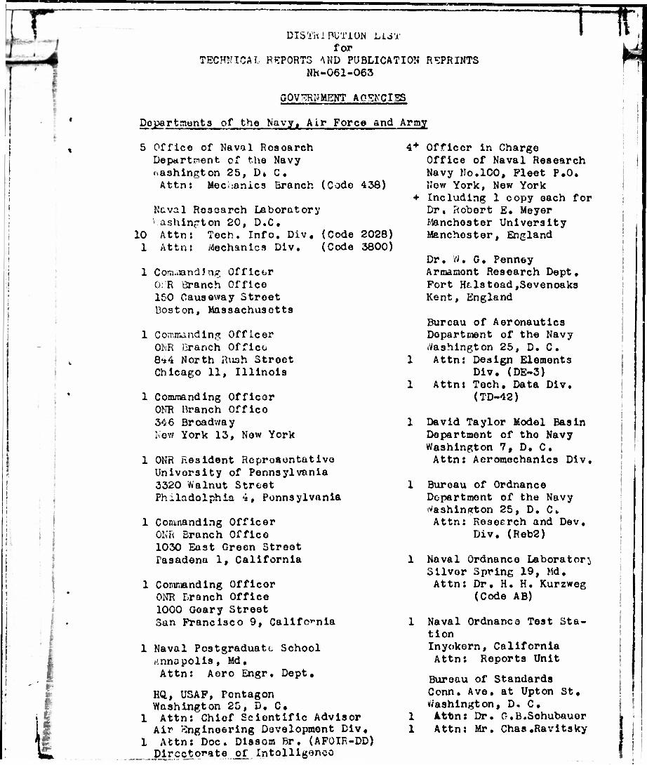
DISTRIBUTION LUT for
TECHNICAL REPORTS AND PUBLICATION REPRINTS NR-061-063
GOVERNMENT AGENCIES
Departments of the Navyt Air Force and Army
5 Office of Naval Rosearch Department cf the Navy Washington 25, D» C. Attn: Mechanics Branch (Code 438)
Naval Ro3oarch Laboratory >.ashin?ton 20, D.C.
10 Attn: Toch. Info. Div. (Code 2028) 1 Attn: Mechanics Div. (Code 3800)
1 Corn..andJng Officer 0:R Branch Office 150 Causeway Street Boston, Massachusetts
1 Con-minding Officer ONR Branch Office 8*4 North Rush Street Chicago 11, Illinois
1 Commanding Officer ONR Branch Office 346 Broadway Now York 13, Now York
1 ONR Resident Representative University of Pennsylvania 3320 Walnut Street Philadelphia 4, Pennsylvania
1 Contnanding Officer ONR Branch Office 1030 East Green Street Pasadena 1, California
1 Commanding Officer ONR Branch Office 1000 Geary Street San Francisco 9, California
1 Naval Postgraduate School rtnnapolls, Md. Attn: Aero Engr. Dept.
Hft, USAF, Pontagon Washington 25, D. C.
1 Attn: Chief Scientific Advisor Air Engineering Development Div,
1 Attn: Doc. Dissom Br. (AFOIR-DD) Directorate of Intolllgeneo
4* Officer in Charge Office of Naval Research Navy Ho.100, Fleet P.O. New York, New York
• Including 1 copy each for Dr, Robert E. Meyer Manchester University Manchester, England
Dr, W. G, Penney Armament Research Dept. Fort Htlstoad,Sevenoaks Kent, England
Bureau of Aeronautics Department of the Navy Washington 25, D. C.
1 Attn: Design Elements Div. (DE-3)
1 Attn: Tech. Data Div. (TD-42)
1 David Taylor Model Basin Department of tho Navy Washington 7, D. C.
Attn: Aeromechanics Div.
1 Bureau of Ordnance Department of the Navy rtashinRton 25, D. C» Attn: Reseerch and Dev.
Div. (Reb2)
1 Naval Ordnanco Laboratory Silver Spring 19, Md. Attn: Dr. H. H. Kurzweg
(Code AB)
1 Naval Ordnance Test Sta- tion Inyokern, California Attn: Reports Unit
Bureau of Standards Conn. Ave. at Upton St. Washington, D, C.
1 Attn: Dr. O.B.Sohubauor 1 Attn: Mr. Chas.Ravitsky

distribution list p2
1 Contral Mr Documents Office U.B. Building Wright-Patterson Air Force Base Dayton; Ohio
1 Commanding Goncrul 'Jqs, Air Material Command .iright-Patterson Air Forco Base Dayton, Ohio Attn: KCKIXD4
1 Flight Rcsoarch Laboratory -ripht-r'attorson Air Forco base Dsytcn, Ohio (.CKR-S3) Attn: Mr. L. 3. «u3Sorman
1 Office of the. Chlof of Ordnance Department of the Army Pentagon, -Voshington, D. C. Attn: Rosoarch and Dov. Div,
1 Ballistic Research Laboratories Aiioriocn Proving Ground Abordecn, Maryland Attn: Dr. C. W. Lames on
1 National Advisory Committee for Aeronautics 1724 F Stroet N. vV . Washington, D. C« Attn: Rosoarch Info. Div.
1 Diroofccr,, NACA Amos Aeronautical Laboratory Moffott Field, California Attn: Mr. H, J. Allon
1 Director, NACA Langloy Aeronautical Laboratory Langloy Air Force Base, Vu. Attn: Mr. J. Stack
1 Director, NACA Lewis Flight Propulsion Lab. Cleveland 11, Ohio Attn: Mr, A. Silversteln
1 Research and Development Board Department of Defense
1 Armed Forces Special -capons Project Pentagon, Washington, D.C. P.O. Box 2610 Attn: Info. Reqt.Board Washington, D.C. Attn: Col. G. F. Blunda
Associated Individuals and Government Sponsored Laboratories
1 Dr. -iin, Bollay P.O. Box 89 Downey, California
1 Dr. L. R. Hafstad 1901 Constitution Ive. Washington 25, D. C.
1 Dr» R, M. Mott-Smith 50 Memorial Drive Cambridge, Mass.
1 Dr. G. N. Patterson 17 Langmulr Crescent Toronto 9, Ontario
1 Dr. D. R. White
Applied Physics Laboratory 8621 Ooorgia Avonuo SiIvor Spring, Maryland
1 Attn: Supervisor Tech. Reports
1 Attn: Dr. F. K. Elder
1 Arnold Research Organiza- tion, Inc. Rm. 210, 522 Olive Stroet St. Louis, Missouri Attn: Mr. F, Smelt
Cornoll Aeronautical Laboratory
4455 Gonosoe Stroot Buffalo 21, Now York
Goneral Electric Resoarch Laboratory 1 Attn: Dr. J. V. Foa Schonectady, N. Y, 1 Attn: Dr, 0. Rudingor

h -T|P^r-
I s.
•
distribution Hat p5
1 Jot Propulsion Laboratory Pasadena, California Attn: Librarian
1 Arthur D, Little, Ino. 30 iacmorlal Drive Cambridge 42, Mass* Attn: Dr. »"»m. Gordon
1 Los Alamos Scientific Laboratory Santa ?c, N. &ox4 Attn: J-l Division
1 niclpar Electronics Inc. 452 Swann Avenue Alexandria, Va. Attn: Mr. W. L. Mttlg
1 Midwest Rosoarch Institute Physics Department 4049 Pennsylvania Avenuo Kansas City, Uo, Attn: Mr. K. L. Sandefur
1 Ordnance Aerophyslcs Laboratory Daingorfiold, Texas Attn: Mr. J. B. Arnold
1 Projoot METEOR Mass. Institute of Technology Cambridge 33, Mass* Attn: Librarian, Rr.
22-001
1 Project SQUID Princeton Univorslty Princoton, N-. J. Attn: Librarian
1 RAND Corporation 1500 4tti Stroot Santa Monica, California Attn: Dr. R. VU • Kruogor
1 San?.la Corporation c/o CG, Sandia Baso Albuquorquo, N. Mox. Attn: Appl. Physics Div.
Project HERMES General Eloctric Company Schonootady, New York Attn: Mr. C. K. Bauor
mTIV^RSITV TTnTSTICttTrtRS
I
)
1 Amherst College Department of Physics Amhorst, Mass. Attn: Prof. A, Arons
1 Polytochnlc Institute of Brooklyn 85-89 Livingston Stroot Brooklyn 2, New York Attn: Dr. A. Porri
Brown University Providence 12, Rhode Island
1 Mctcalf Resoarch Laboratory Attn: Dr. D. P. Hornig
1 Engineering Division Attn: Professor J. Kostin
California Instltuto of Technology Pasadena 4, California
1 Attn: Dr. H. W. Leipmann 1 Attn: Dr. H. T. Nagamatau
«_ nnn.Ht.^dl iAhoT.ltorV
1 John Hopkins University Lcpt. of Aeronautical Engineering Baltimore 18, Maryland Attn: Dr. P. H. Clausor
1 Harvard University Dopt. of Appliod Physics Cambridge 38, IJass • Attn: Dr. H, V. Emmons
University of Illinois Urbana, Illinois
1 Attn: Dr. C. H. Fletcher 1 Attn: Dr. A. H. Taub
1 Armour Rosoarch Fonndati* Illinois Institute of » Technology 3300 Federal Street Chicago 10, Illinois Attn t Dr. 5. RavnO?

distribution list p4
1 University of California Engineering Research Projects Berkeley 4, California Attn: Dr. R. 0. Polsom
1 Case Instituto of Technology Clovuland 6, Ohio Attn: Prof. Guatav Kuortl Div. of Aeronautical Engr.
1 Lehigh University Phyaica Departnent Botrlehcra, Pennsylvania Attn: Dr. R, J, Emrich
1 University of Maryland Institute for Fluid Dynamics College Park, Maryland Attns Dr, M, M, Martin
J..
1 University of Chicago Yorkos Observatory William Bay, .iceens in Attn: Dr. S. Chandrasokhar
1 Cornell University Grad, School of Aero. Engr. Ithaca, New York Attn: Dr. A. Kantrowitz
University of Michigan Ann Arbor, Michigan
1 At en: Dr. A. M. Kuethe Dept. of Aeronautical Engr.
1 Attn: Dr. Otto Laporte Department of Physics
1 University of Minnesota Dept. of Aeronautical Engr. i-inneapolia 14, Minnesota Attn; Dr. J. D. Akomian
Now York University Institute of Math and Moch. 53 :<aahin^ton Squaro So, Hew York 12, New York
1 Attn: Dr. h. U. Courant 1 ;.ttn: Dr. K. 0. Pricdrichs
Mass. Institute of Technology Cambridge 39, Mass. Attn: Dr. J. C. Kunsakor Aeronautical Engineering Dept, Attn: Dr. H. Guyford Stover Aeronautical Engineering Dept, Attn: Dr. C. C. Lin Mathematics Department
Pennsylvania State College Physics Department State Collogo, Pennsylvania Attn: Dr, R, G, Stonor
Princeton University Princeton, Now Jorroy
L Attn: Dr. W. Bloakney Palmer Physioal Laboratory
I. At In; Dr. D, Bershador Aeronautioal Attn: Mr, L, Aeronauticul Httn: Dr. J.
Engr, Dopt, Lees Engr, Dopt, vonNeumann
Instituto for Advanced Sl;udy
1 University of Virginia Department of ?hy3ics Charlottosvlllo, Va, Attn: Dr, J, »*• Beams
University of Wisconsin Department of Chomistry Madison, is cons in Attn: Dr. J, 0. Hirschfelder
Yalo University Now Haven, Connecticut Attn: Dr. J. G, Kirkwood Department of Chomistry
• I ill
Recommended

![Gainesville Daily Sun. (Gainesville, Florida) 1908-03-31 [p 2].ufdcimages.uflib.ufl.edu/UF/00/02/82/98/01251/00644.pdfyAr the tho the tho not tho the ND you the tho the the the the](https://img.pdfslide.us/doc/110x75/5fe8e52c24233042ec60f914/gainesville-daily-sun-gainesville-florida-1908-03-31-p-2-yar-the-tho-the.jpg)