MCS Based Design for GSHPs –
“Horses for Courses” GSHPA Energy Expo – Stone – Sept 2017
Robin Curtis – GeoScience Ltd
Dog ‘n Pony Show
Robin – on “MCS”why / how / what / when / where
Chris – on “not‐the‐MCS” approachwhy / how /when /where
Objectives
‐ Background setting‐ Underlying reasoning & approach‐ The MIS‐3005 design “products” ‐ Focus on the ground loop sizing &‐ Hydraulics
New ground loop sizing toolsfor Domestic GSHP installationsin the UK
Robin Curtis & Tom Pine ‐ GeoScience Ltd. Chris Wickins ‐ UK Dept. of Energy & Climate Change
EGC – Pisa June 2013
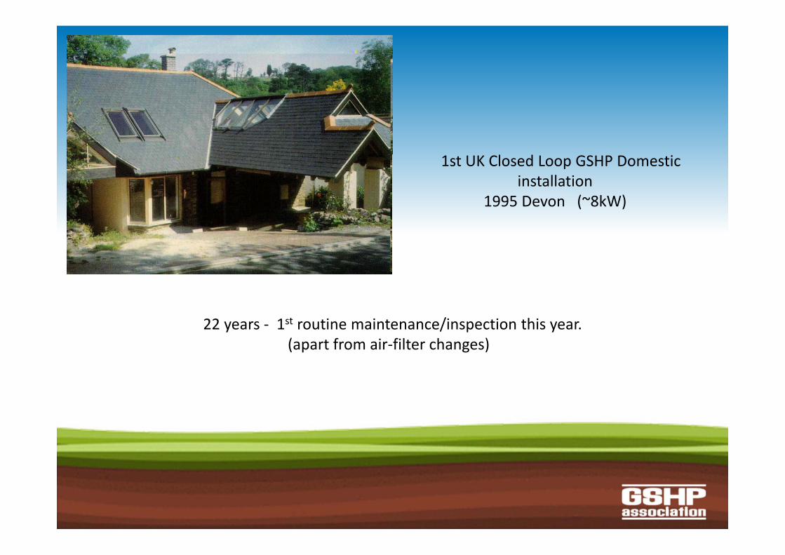
1st UK Closed Loop GSHP Domesticinstallation
1995 Devon (~8kW)
22 years ‐ 1st routine maintenance/inspection this year. (apart from air‐filter changes)

Background
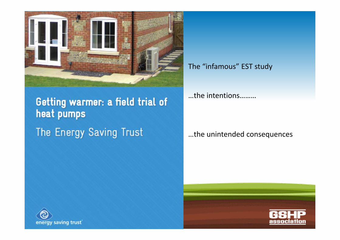
The “infamous” EST study
…the intentions………
…the unintended consequences

DECC steps in…….
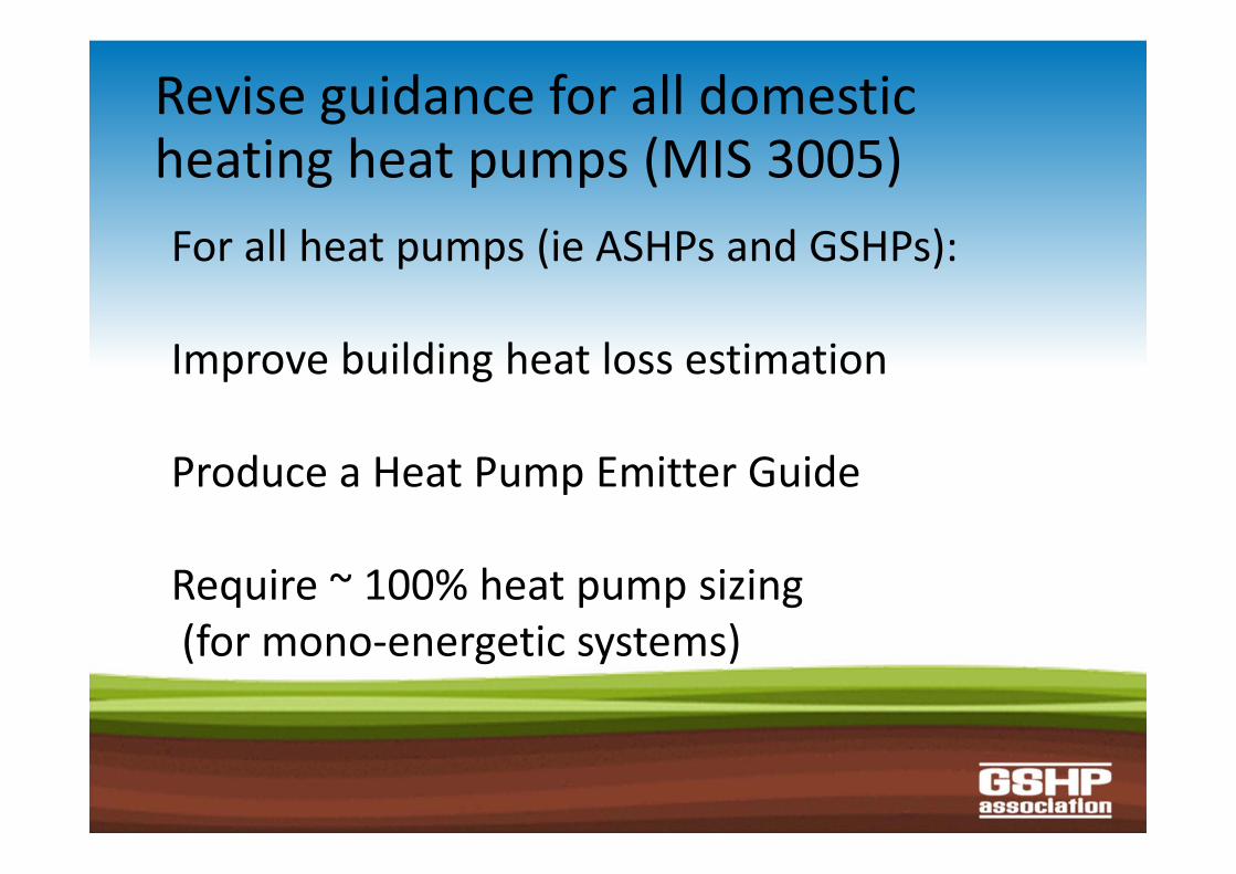
Revise guidance for all domesticheating heat pumps (MIS 3005) For all heat pumps (ie ASHPs and GSHPs):
Improve building heat loss estimation
Produce a Heat Pump Emitter Guide
Require ~ 100% heat pump sizing(for mono‐energetic systems)
Specifically for GSHPs ‐
New guidance for ground loop sizing
Guidance for hydraulic design
LASHUP ‐ 2Ground related issues
DECC ‐ 9 Mar 2011

“Crazy”paving ?
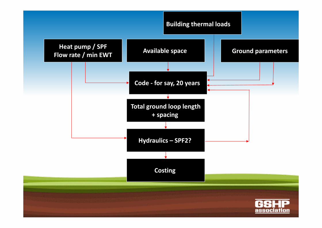
Ground parameters
ffBuilding thermal loads
Available space Heat pump / SPFFlow rate / min EWT
Total ground loop length+ spacing
Code ‐ for say, 20 years
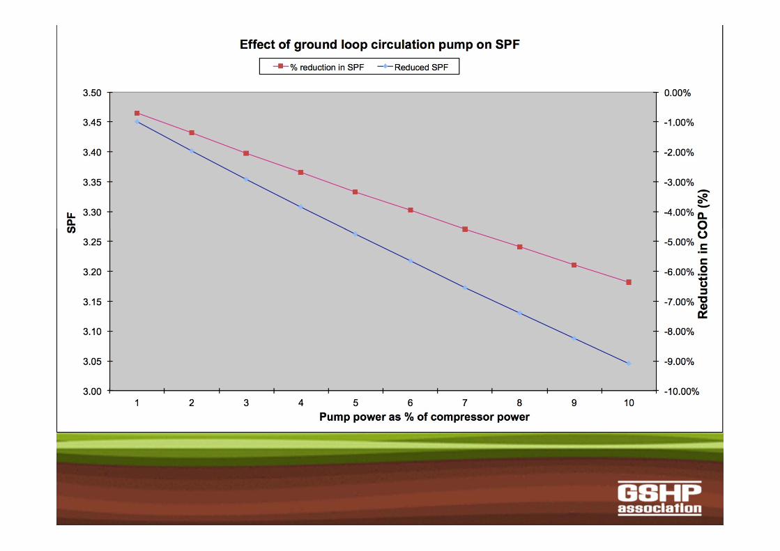
Hydraulics – SPF2?
Costing
Heat loss / energy ?
Energy assessment for closed loop GSHPs–“THE” fundamental
difference(compared to all fossil fuel boilers, direct electric, and ASHPs )
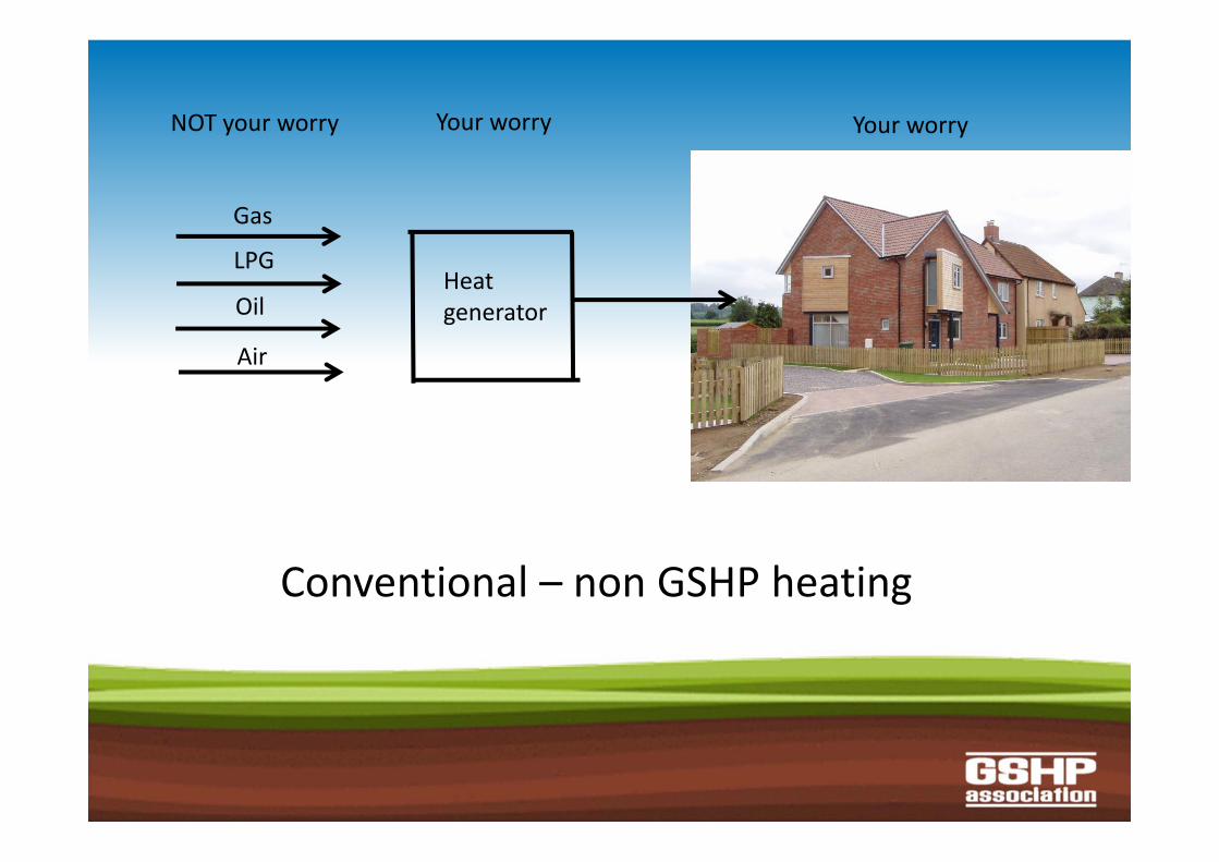
Heat generator
NOT your worry Your worry Your worry
Gas
LPG
Oil
Air
Conventional – non GSHP heating
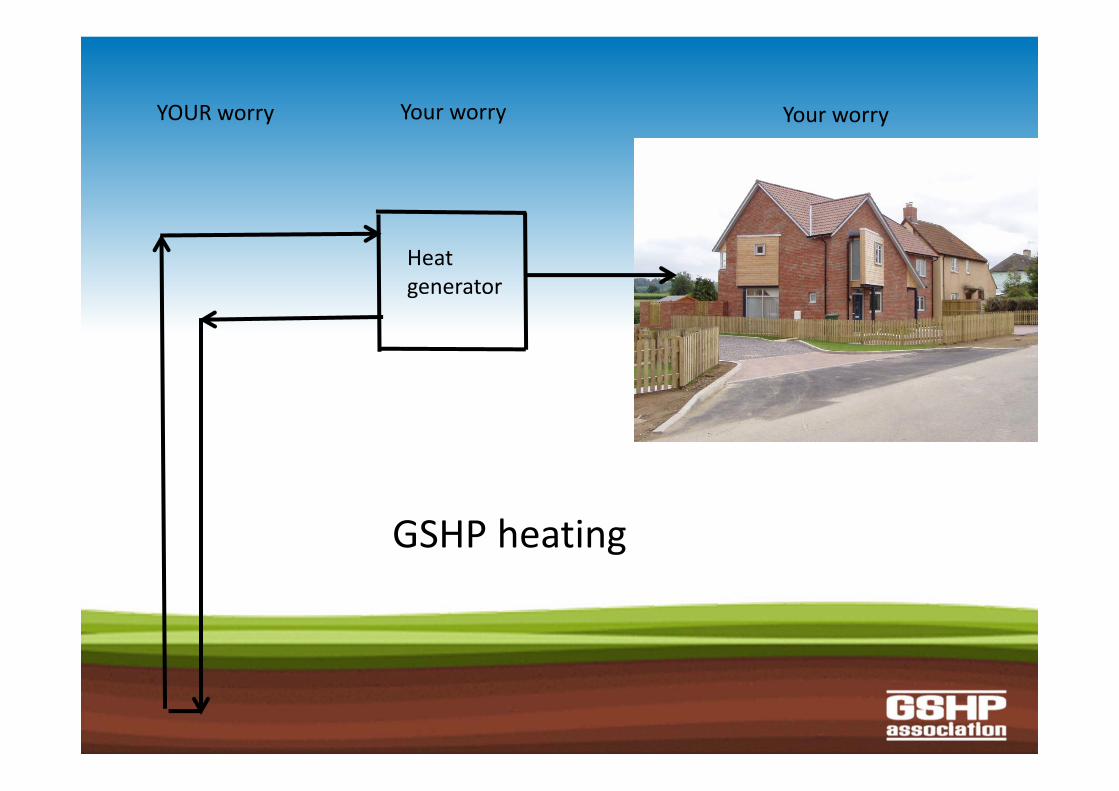
Heat generator
YOUR worry Your worry Your worry
GSHP heating
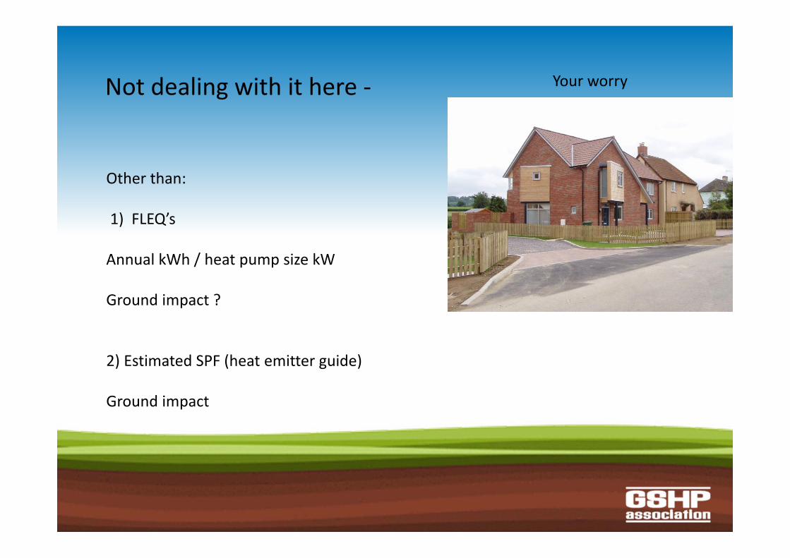
Your worryNot dealing with it here ‐
Other than:
1) FLEQ’s
Annual kWh / heat pump size kW
Ground impact ?
2) Estimated SPF (heat emitter guide)
Ground impact
Ground loop sizing / design
Underlying philosophy
• Conservative• Simple – available to all• Paper based – no HW/SW version issues• Domestic heating + DHW only (<45kW)• To obtain acceptable SPFs• Not the best or cheapest
Previous methods ? Some use of software, eg EED, GLHEPRO, GLD, CLGS
European manufacturers’ software
VDI 4640
The well known ROT method
Concerns ? Relevance to UK conditions ?
“Ground” rules
100% sizing – for mono‐energetic systems
Minimum entering water temperature(EWT) O°C(after 20 years) – to maintain SPF
Boreholes Fixed parameters:single 32mm U‐tube, specified borehole resistance, minimum spacing defined
Variable parameters:
Ground equilibrium temperatureThermal conductivityAnnual thermal loads (Run hours / FLEQ)
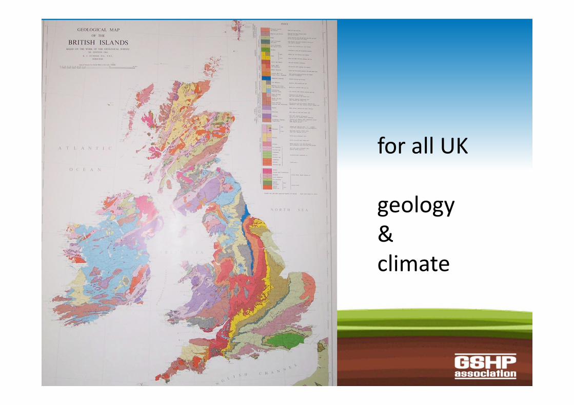
for all UK
geology &climate
Boreholes
Over a (UK relevant) range of k, ground temperature and FLEQ
Run: EED, GLHEPRO
Make some check comparisons with VDI 4640 and GLD.
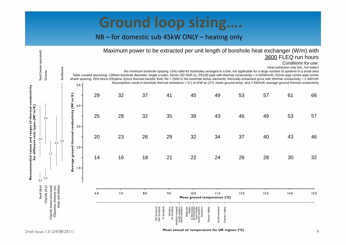
Ground loop sizing….
Geo En er gy
NB – for domestic sub 45kW ONLY – heating only
Draft Issue 1.0 (24/08/2011)
5.0
4.0
3.0
2.0
1.0
Ave
rage
gro
un
d t
her
mal
co
nd
uct
ivit
y (W
/m/K
)
Mean ground temperature (oC)6.0 7.0 8.0 9.0 10.0 11.0 12.0 13.0 14.0 15.0
NE
Sco
tland
NW
Sco
tland
E S
cotla
nd
Bor
ders
W S
cotla
nd
Nor
ther
n Ire
land
Nor
th-e
aste
rnN
orth
-wes
tern
Mid
land
sW
ales
E P
enni
nes
W P
enni
nes
Eas
t Ang
liaS
outh
-eas
tern
Sou
ther
n
Sev
ern
Valle
y
Sou
th-w
este
rn
Tham
es V
alle
y
Mean annual air temperature for UK regions (oC)
14
29
25
20
16
32
28
23
18
37
32
26
21
41
35
29
22
45
39
32
24
49
43
34
26
53
46
37
28
57
49
40
30
61
53
43
Rec
om
men
ded
val
ues
an
d r
ange
s o
f th
erm
al c
on
du
ctiv
ity
for
dif
fere
nt
rock
typ
es (
W/m
/K)
32
66
57
46
0.5
Cla
y/si
lt (d
ry)
3.4
Gra
nite
0.4
Sand
(dr
y)
2.4
Sand
(w
ater
-sat
urat
ed)
Cla
y/si
lt (w
ater
-sat
urat
ed)
1.7
Cla
ysto
ne, s
iltst
one
(inc.
slat
es a
nd s
hale
s)
2.2
Sand
ston
e
2.3
9
Maximum power to be extracted per unit length of borehole heat exchanger (W/m) with 3600 FLEQ run hours
Conditions for use:Heat extraction only (inc. hot water)
6m minimum borehole spacing. Only valid for boreholes arranged in a line; not applicable for a large number of systems in a small areaTable created assuming: 130mm borehole diameter; single U-tube; 32mm OD SDR-11, PE100 pipe with thermal conductivity = 0.420W/m/K; 52mm pipe centre-pipe centre
shank spacing; 25% Mono Ethylene Gylcol thermal transfer fluid; Re > 2500 in the borehole active elements; thermally enhanced grout with thermal conductivity = 2.4W/m/KAssumptions result in borehole thermal resistance = 0.1 m.K/W at 12oC mean ground temp. and 2.5W/m/K average ground thermal conductivity
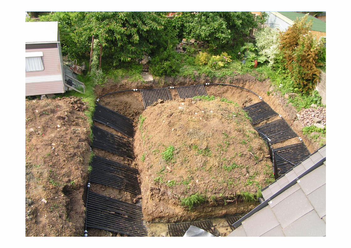
Horizontal systems Conventional EU style loops (Serpentine) , and SlinkiesFixed parameters: Geometrical layouts and pipe sizes defined.
Variable parameters:Ground equilibrium temperatureThermal conductivityAnnual thermal loads (Run hours / FLEQ)+ Temperature “swing” and depth
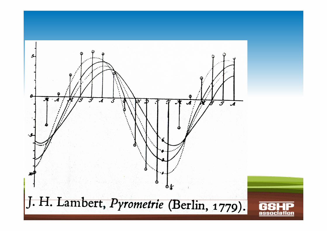
from Tufte
Horizontal systems Over a (UK relevant) range of :k, ground temperature and FLEQ
Run: CLGS
Make some check comparisonswith VDI 4640 and GLD.

Ground loop sizing….NB – for domestic sub 45kW ONLY – heating only
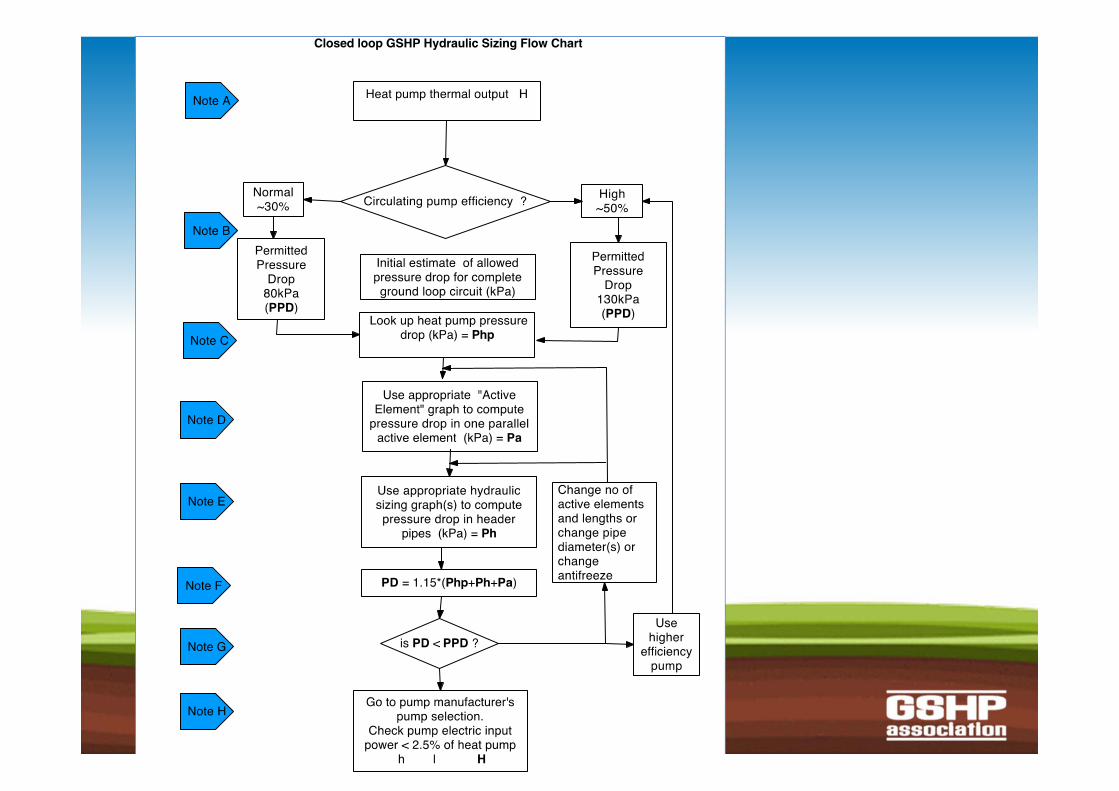
Hydraulics designof closed loop GSHPs
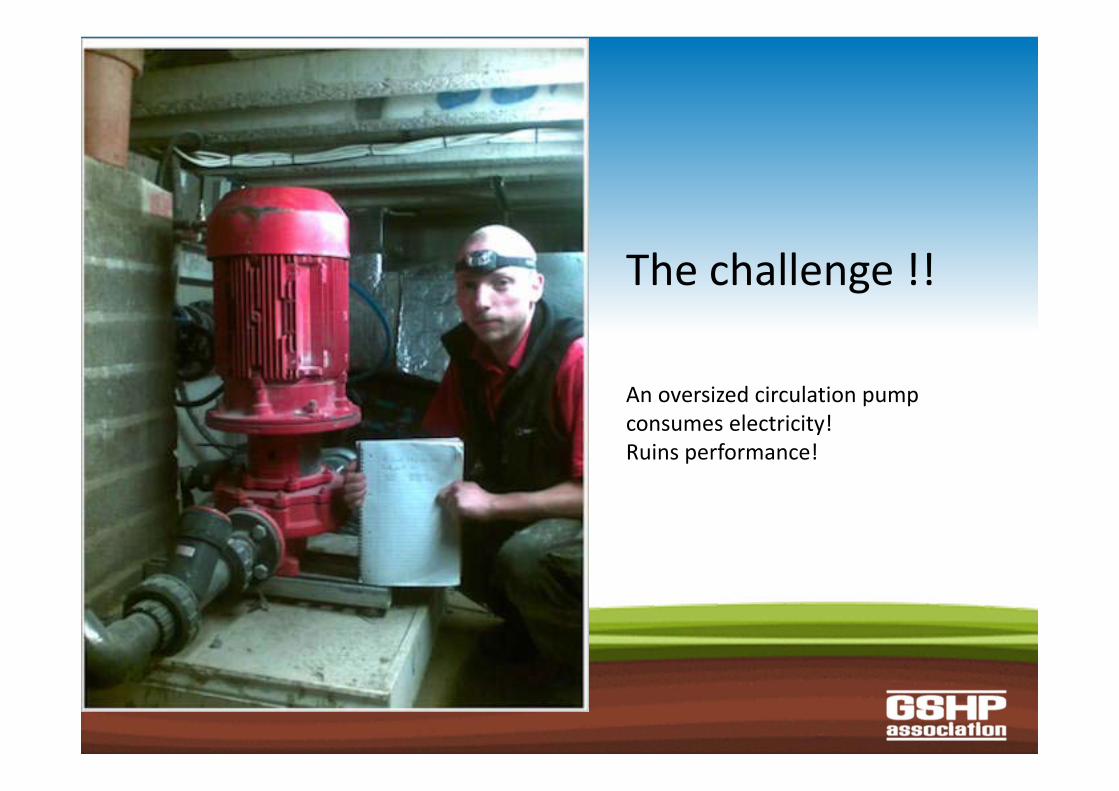
The challenge !!
An oversized circulation pump consumes electricity!Ruins performance!
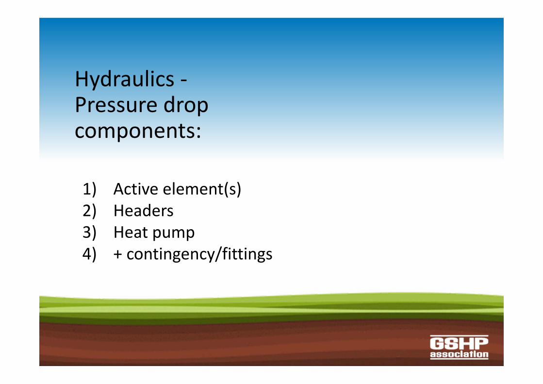
Hydraulics ‐Pressure dropcomponents:
1) Active element(s)2) Headers3) Heat pump4) + contingency/fittings
Hydraulics ‐fixed parameters
• Heat pump flow rate • Non‐laminar – (transition zone)• min % Anti‐freeze
Hydraulics ‐the variables
• Borehole/loop lengths vs number• Pipe diameter • Borehole pipe configuration (1U / 2U)• Header arrangements
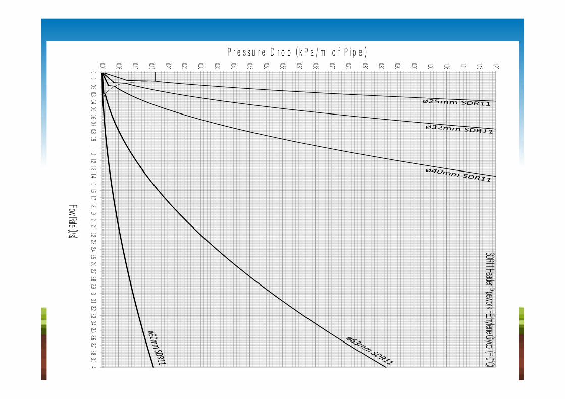
Flow Rate (l/s)
P r e s s u r e D r o p ( k P a / m o f P i p e )
0.00
0.05
0.10
0.15
0.20
0.25
0.30
0.35
0.40
0.45
0.50
0.55
0.60
0.65
0.70
0.75
0.80
0.85
0.90
0.95
1.00
1.05
1.10
1.15
1.20
00.1
0.20.3
0.40.5
0.60.7
0.80.9
11.1
1.21.3
1.41.5
1.61.7
1.81.9
22.1
2.22.3
2.42.5
2.62.7
2.82.9
33.1
3.23.3
3.43.5
3.63.7
3.83.9
4
SDR11 Header Pipework -Ethylene Glycol (-10°C)
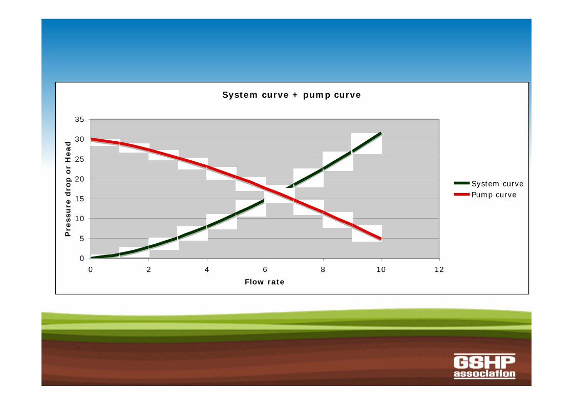
System curve + pump curve
0
5
10
15
20
25
30
35
0 2 4 6 8 10 12Flow rate
Pre
ssu
re d
rop
or
Hea
d
System curvePump curve
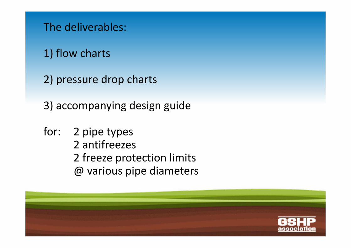
The deliverables:
1) flow charts
2) pressure drop charts
3) accompanying design guide
for: 2 pipe types2 antifreezes2 freeze protection limits@ various pipe diameters
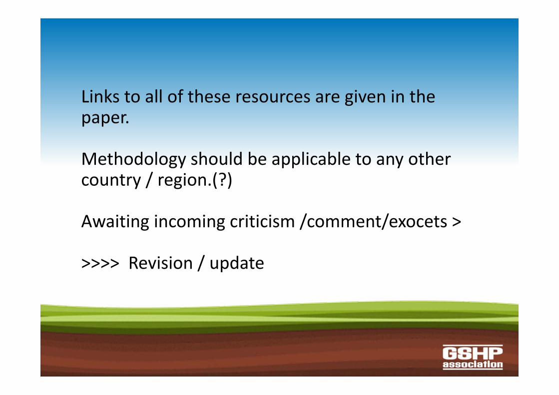
Links to all of these resources are given in the paper.
Methodology should be applicable to any other country / region.(?)
Awaiting incoming criticism /comment/exocets >
>>>> Revision / update

OUTCOME ?
But – if you want to get more advanced…...........
listen in..........
• Thank you.

Ground Loop Design& the limits of MIS 3005
The Many Faces of Building Loads
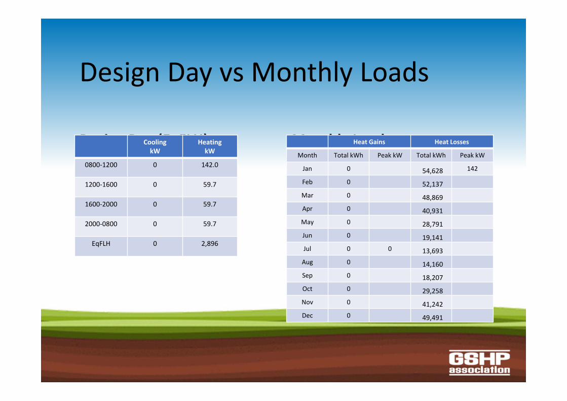
Design Day vs Monthly Loads
Design Day (EqFLH)CoolingkW
HeatingkW
0800‐1200 0 142.0
1200‐1600 0 59.7
1600‐2000 0 59.7
2000‐0800 0 59.7
EqFLH 0 2,896
Monthly LoadsHeat Gains Heat Losses
Month Total kWh Peak kW Total kWh Peak kW
Jan 0 54,628 142
Feb 0 52,137 Mar 0 48,869 Apr 0 40,931 May 0 28,791 Jun 0 19,141 Jul 0 0 13,693 Aug 0 14,160 Sep 0 18,207 Oct 0 29,258 Nov 0 41,242 Dec 0 49,491
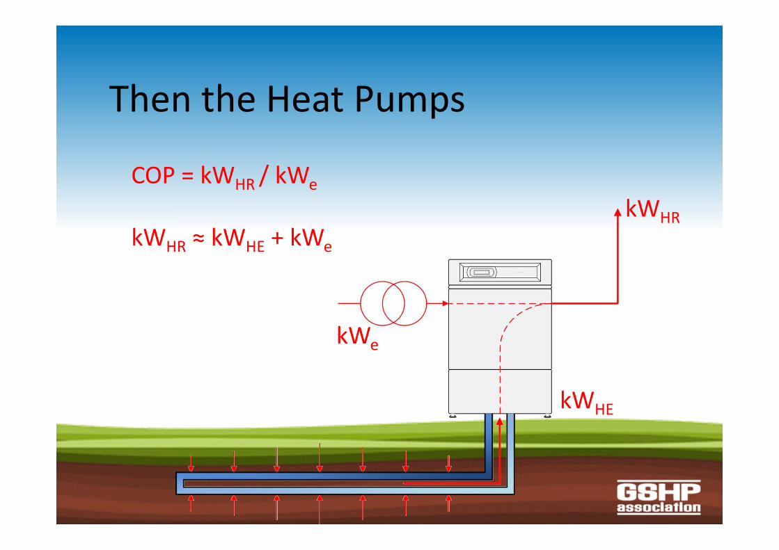
Then the Heat Pumps
kWHR
kWHE
kWe
COP = kWHR / kWe
kWHR ≈ kWHE + kWe
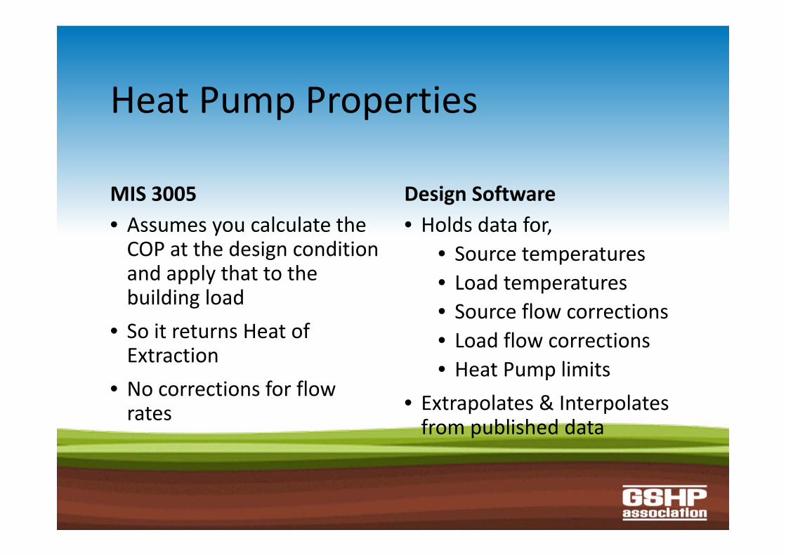
Heat Pump Properties
MIS 3005• Assumes you calculate the COP at the design condition and apply that to the building load
• So it returns Heat of Extraction
• No corrections for flow rates
Design Software• Holds data for,
• Source temperatures• Load temperatures• Source flow corrections• Load flow corrections• Heat Pump limits
• Extrapolates & Interpolates from published data
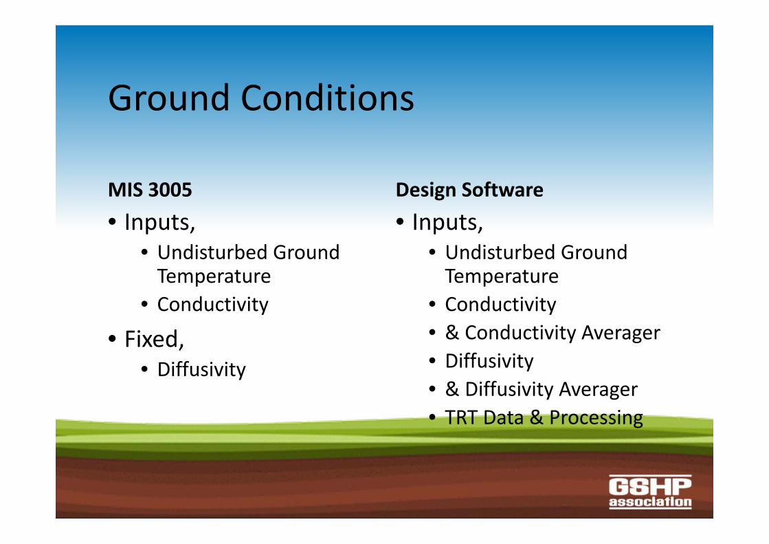
Ground Conditions
MIS 3005• Inputs,
• Undisturbed Ground Temperature
• Conductivity
• Fixed,• Diffusivity
Design Software• Inputs,
• Undisturbed Ground Temperature
• Conductivity• & Conductivity Averager• Diffusivity• & Diffusivity Averager• TRT Data & Processing
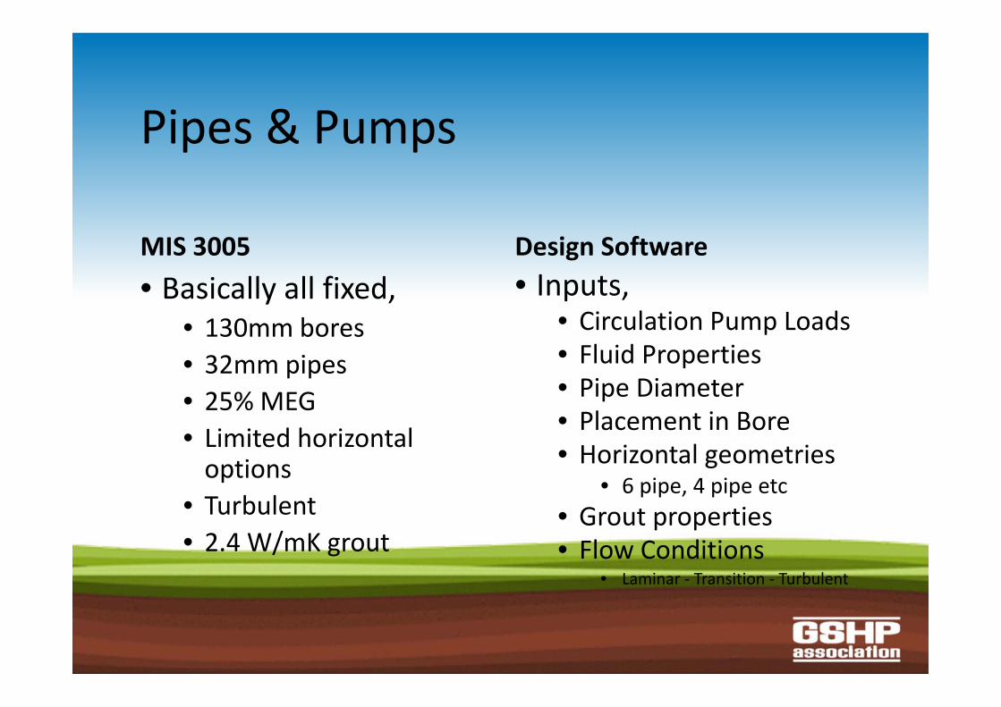
Pipes & Pumps
MIS 3005• Basically all fixed,
• 130mm bores• 32mm pipes• 25% MEG• Limited horizontal options
• Turbulent• 2.4 W/mK grout
Design Software• Inputs,
• Circulation Pump Loads• Fluid Properties• Pipe Diameter• Placement in Bore• Horizontal geometries
• 6 pipe, 4 pipe etc• Grout properties• Flow Conditions
• Laminar ‐ Transition ‐ Turbulent
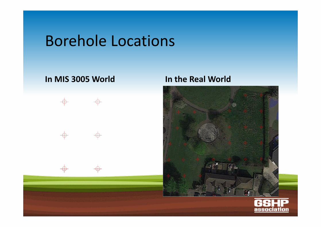
Borehole Locations
In MIS 3005 World In the Real World
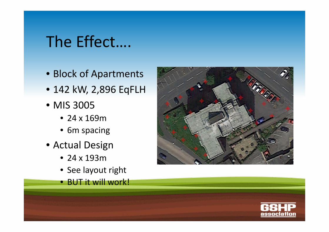
The Effect….
• Block of Apartments• 142 kW, 2,896 EqFLH• MIS 3005
• 24 x 169m• 6m spacing
• Actual Design• 24 x 193m• See layout right• BUT it will work!
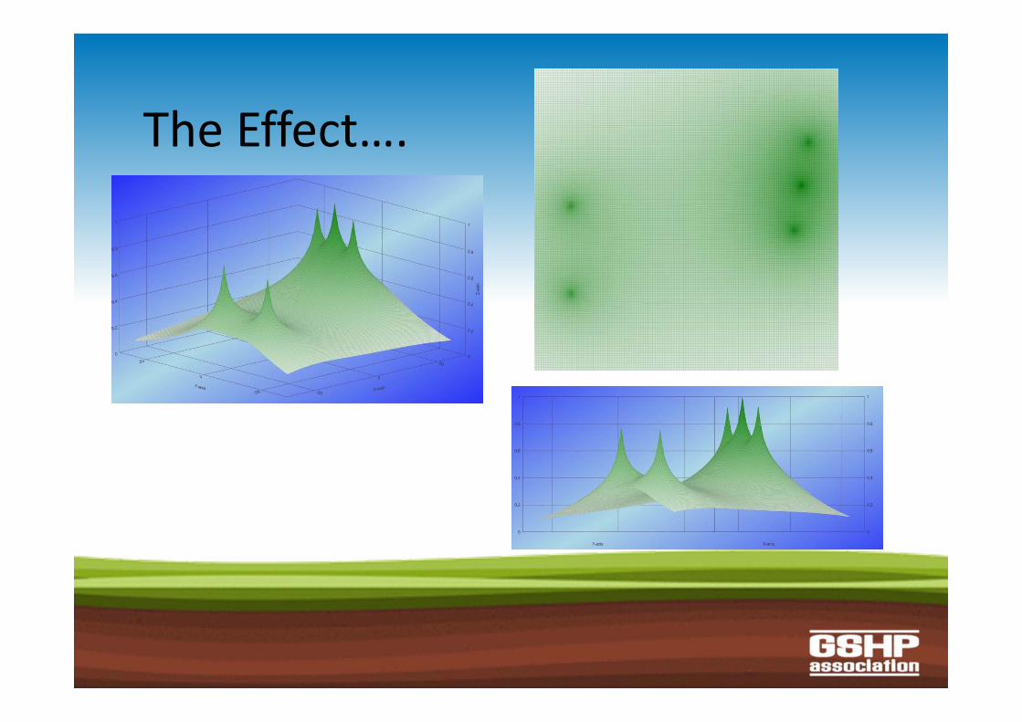
The Effect….
Take Away Messages….
• Exceptions to the MIS 3005 tables do exist• Know the limits of look‐up table “design”• Look out for the warning signs• Pipe is cheap!• Keep your spacings up – Borehole & Slinky Pitch• Consider further training• Please, Please, Please ask for help
Recommended