MCD MULTICHANNEL LED DRIVER INSTRUCTION MANUAL
rev. 100616

2
HEAD OFFICE LED Microsensor NT, LLC ● R&D CENTRE Microsensor Technology, LLC
194223, postbox 100, St.Petersburg, Russia ● [email protected] ● www.lmsnt.com
TABLE OF CONTENTS
General Information 3
Application 3
Features 3
Operation conditions 3
Driver layout 4
Operating mode description 5
Operating instruction 6-7
Driver connections 8
Technical characteristics 9

3
HEAD OFFICE LED Microsensor NT, LLC ● R&D CENTRE Microsensor Technology, LLC
194223, postbox 100, St.Petersburg, Russia ● [email protected] ● www.lmsnt.com
GENERAL INFORMATION
Application
MCD driver is a utility board that unites several functions: - power supply of arrays comprising of Mid-IR LEDs, supporting up to 8 channels; - photodiode signal processing and amplification; - synchronisation of LED and photodiode signals.
Compatibility table
One-element LED models
LmsXXLED
LmsXXLED-R
LmsXXLED-RW
LmsXXLED-TEM
LmsXXLED-TEM-R
Standard multielement LED models
LmsXXLED-4M
LmsXXLED-4M-R
LmsXXLED-4M-RW
LmsXXLED-4M-TEM
LmsXXLED-4M-TEM-R
Lms18-..-23LED-6M
Lms18-..-23LED-6M-TEM
Note! Please contact us to specify compatibility of custom multielement LED models.
Features Pulse mode operation (mode that provides maximum peak optical power).
LED current amplitude and pulse duration are preset by manufacturer according to a customer’s request.
Ability to work either with PD models without a built-in preamplifier (enabling an on-board MCD preamplifier) or with PD models with a built-in preamplifier*.
Built-in 8-channel synchronous detector, which provides synchronisation of LED signals with a photodiode preamplifier and further signal amplification.
Operation conditions Indoor operation only. Ingress Protection Rating IP00.
* You should choose the photodiode model (with or without a built-in preamplifier) to work with MCD driver beforehand,
since the driver is able to operate with only one photodiode type and should be tuned in advance accordingly.

4
HEAD OFFICE LED Microsensor NT, LLC ● R&D CENTRE Microsensor Technology, LLC
194223, postbox 100, St.Petersburg, Russia ● [email protected] ● www.lmsnt.com
DRIVER LAYOUT
1. Power input terminal block.
2. LED connection contacts.
3. Photodiode connection contacts.
4. Photodiode preamplifier connection terminal blocks.
5. Synchronous detector signal output contacts.
6. Output signal gain adjustment potentiometers.
Note! Please refer to your provider if you have any questions.
1
3
5
6
+
-
2
+ - + - + -
+ -
+ - + - + - + - + -
GND channel 1-8 anodes
ch.1 ch.2 ch.3 ch.4 ch.5 ch.6
ch.7
ch.8
4
GND + GND +5V
5
HEAD OFFICE LED Microsensor NT, LLC ● R&D CENTRE Microsensor Technology, LLC
194223, postbox 100, St.Petersburg, Russia ● [email protected] ● www.lmsnt.com
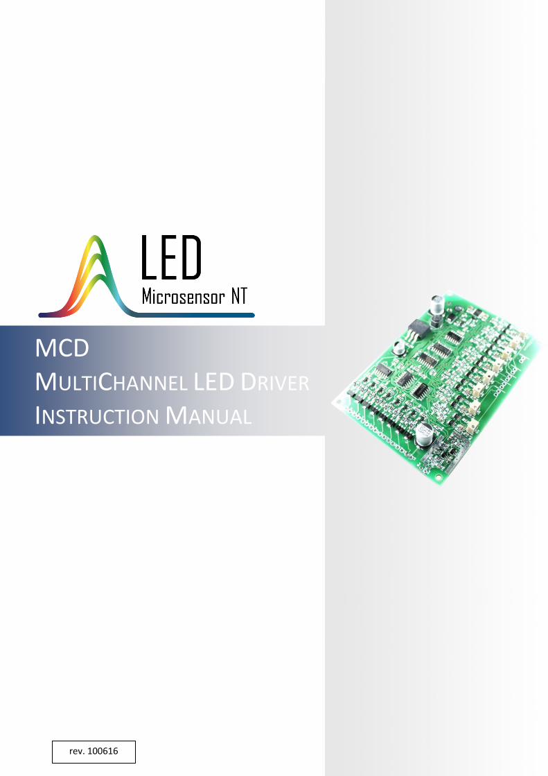
OPERATING MODE DESCRIPTION
MCD driver drives LEDs in a pulse mode. This mode provides LED maximum peak
optical power. LED current value is 0.4 A per channel (by default), pulse duration value
of every channel is 20 µs (by default). Frequency of each channel is 500 Hz; 8-channel
frequency is 4 kHz, this corresponds to photodiode reading frequency.
Every channel lights up sequentially; this enables scanning of a certain spectral
range covered by a multielement LED array.
Pulse mode current-time relation.
Pulse duration and current values can be readjusted by manufacturer.
250µs
channel 1
channel 2
channel 3
channel 4
channel 5
channel 6
channel 7
channel 8
250µs
250µs
250µs
250µs
250µs
250µs
20µs 2ms

6
HEAD OFFICE LED Microsensor NT, LLC ● R&D CENTRE Microsensor Technology, LLC
194223, postbox 100, St.Petersburg, Russia ● [email protected] ● www.lmsnt.com
OPERATING INSTRUCTIONS
1. Carefully and securely connect (via soldering) cathode/anode pins of the LED array
with LED driving contacts (2).
Note! Picture above is for illustration only. Pay your attention to LED electrodes
configuration appropriate to your LED array referring to the technical report for the
array. Also observe the polarity of each element of the array: “P1”, ”P3”, “P5”, ”P7”,
“P9”, ”P11”, “P13”, ”P15” contacts should be connected to the anodes of LEDs.
Improper connection may cause LED damage.
Note! LED matrix case must be electrically isolated from the ground.
Important! You should choose the photodiode model (with or without a built-in
preamplifier) to work with MCD driver beforehand, since the driver is able to operate
with only one photodiode type and should be tuned in advance accordingly. Take one of
the two following steps (2a or 2b) basing on your choice.
2a. Carefully and securely connect (via soldering) a photodiode with photodiode
connection contacts (3). Photodiode cathode and GND should be electrically connected.
Note! Ensure the wires’ shortest possible length between a photodiode and MCD
board.
Note! Provide reliable screening of the wires.
LED input contacts
LED + pins
LED - pins
photodiode
cathode
anode
GND
photodiode input contacts
key
7
HEAD OFFICE LED Microsensor NT, LLC ● R&D CENTRE Microsensor Technology, LLC
194223, postbox 100, St.Petersburg, Russia ● [email protected] ● www.lmsnt.com
OPERATING INSTRUCTIONS
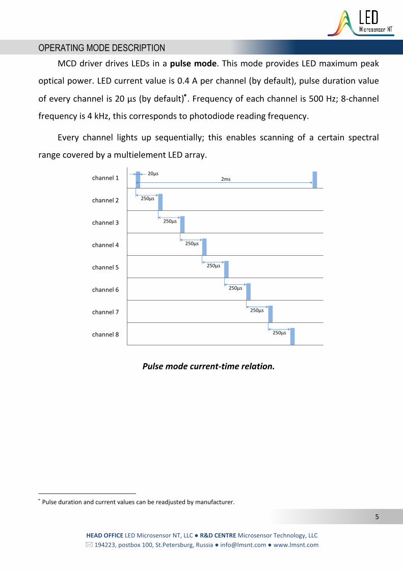
2b. If you use LMSNT photodiode with a built-in preamplifier (LmsXXPD-XX-PA models),
then connect preamplifier cords to preamplifier input terminal blocks (4) as following:
White cord – to the power output “+”; Brown cord – to the power output “0”;
green cord – to the signal input “+”; Yellow cord – to the signal input “0”
3. Connect signal output contacts (5) with signal observing device (multimeter,
oscilloscope or PC via ADC).
4. In case of need adjust amplification signal gain for each channel with the help of the
appropriate potentiometers (6).
6. Connect a power supply to the power input (1).
Note! Please follow the requirements presented in the table on the “Technical
Characteristics” page to provide driver’s faultless operation.
12V power input contacts
signal output contacts
oscilloscope
photodiode with a built-in preamplifier
signal input terminal block
5V power output terminal block

8
HEAD OFFICE LED Microsensor NT, LLC ● R&D CENTRE Microsensor Technology, LLC
194223, postbox 100, St.Petersburg, Russia ● [email protected] ● www.lmsnt.com
DRIVER CONNECTIONS
MCD connections
Power input DC 12V 0.25A
Signal gain adjustment potentiometers (1x-10x)
Photodiode input connection
MCD
External device: oscilloscope or PC via DAQ
+
GND
GND
ch.1 ch.2
GND
ch.3 ch.4 ch.5 ch.6
ch.7
ch.8 +
-
LEDs input connection
+ - + -
+ - + -
+ -
+ -
+ -
+ -
ch.1
ch.2
ch.3
ch.4
ch.5
ch.6
ch.7
ch.8
“+” of channels
1 2 3 4 5 6 7 8
Signal output connection
Photodiode preamplifier input connection
GND

9
HEAD OFFICE LED Microsensor NT, LLC ● R&D CENTRE Microsensor Technology, LLC
194223, postbox 100, St.Petersburg, Russia ● [email protected] ● www.lmsnt.com
TECHNICAL CHARACTERISTICS
Input voltage +12 V, stabilized
Voltage tolerance -5..+5 %
Input current max. 0.25 A Board dimensions 105×70×15 mm
Signal output voltage amplitude 11 V (-4 V for inverted photodiode signal)
Fixed parameters
Pulse duration 20 µs
Frequency (per channel) 0.5 kHz Frequency (8 channels) 4 kHz
Output current amplitude 0.4 A
Adjustable parameters Output signal gain 1x-10x
Pulse duration and current values in the table are default, but can be preadjusted by manufacturer.
Recommended