Mathematical Model of Rockmass Behaviour in Underground Coal
Gasification
National Mining UniversityNational Mining University
Vasil Vasil LozynskyyLozynskyy
Research supervisorResearch supervisorV.S FalshtynskyyV.S Falshtynskyy
Language adviserLanguage adviserN.M N.M
NechayNechay
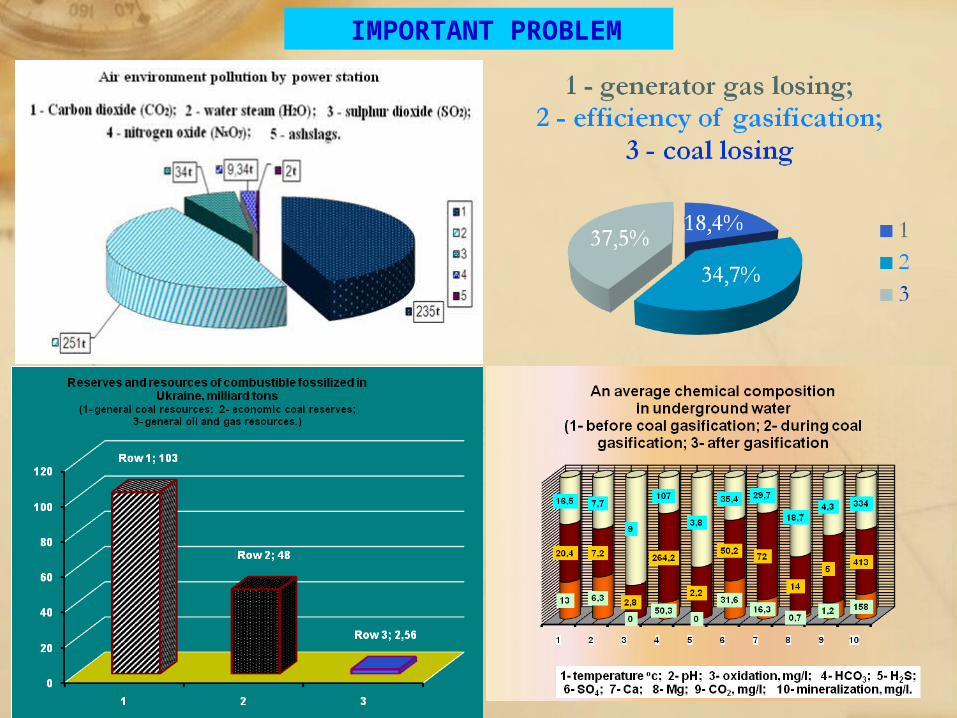
IMPORTANT PROBLEM
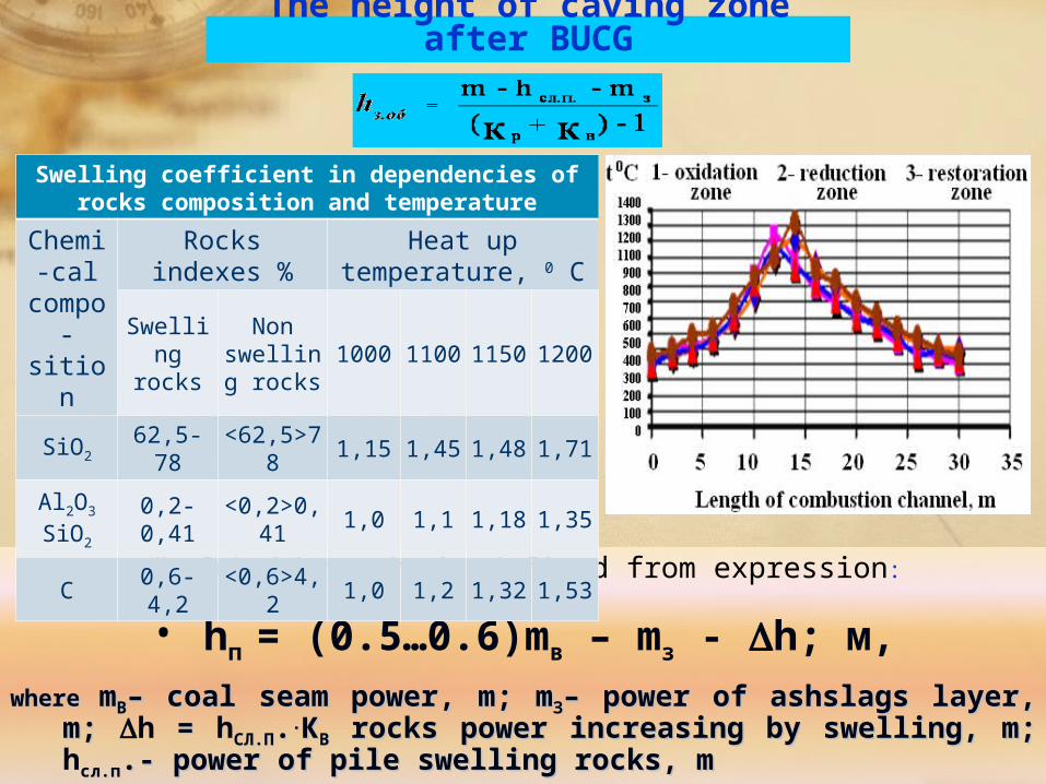
The height of caving zone after BUCG
Subsidence hп is defined from expression:
• hп = (0.5…0.6)mв – mз - h; м,
wherewhere mmBB– – coal seam powercoal seam power, , mm; ; mmЗЗ–– power of ashslags layer power of ashslags layer, , mm; ; h = = hСЛ.ПСЛ.П....ККBB rocks power increasing by swellingrocks power increasing by swelling, , mm; ; hсл.псл.п.- .- power of pile swelling rockspower of pile swelling rocks, , mm
Swelling coefficient in dependencies of rocks composition and temperature
Chemi-cal
compo-sition
Rocks indexes %
Heat up temperature, 0 C
Swelling rocks
Non swelling
rocks1000
1100
1150
1200
SiO2 62,5-78<62,5>
781,15 1,45 1,48 1,71
Al2O3
SiO2
0,2-0,41
<0,2>0,41
1,0 1,1 1,18 1,35
C 0,6-4,2<0,6>4,
21,0 1,2 1,32 1,53
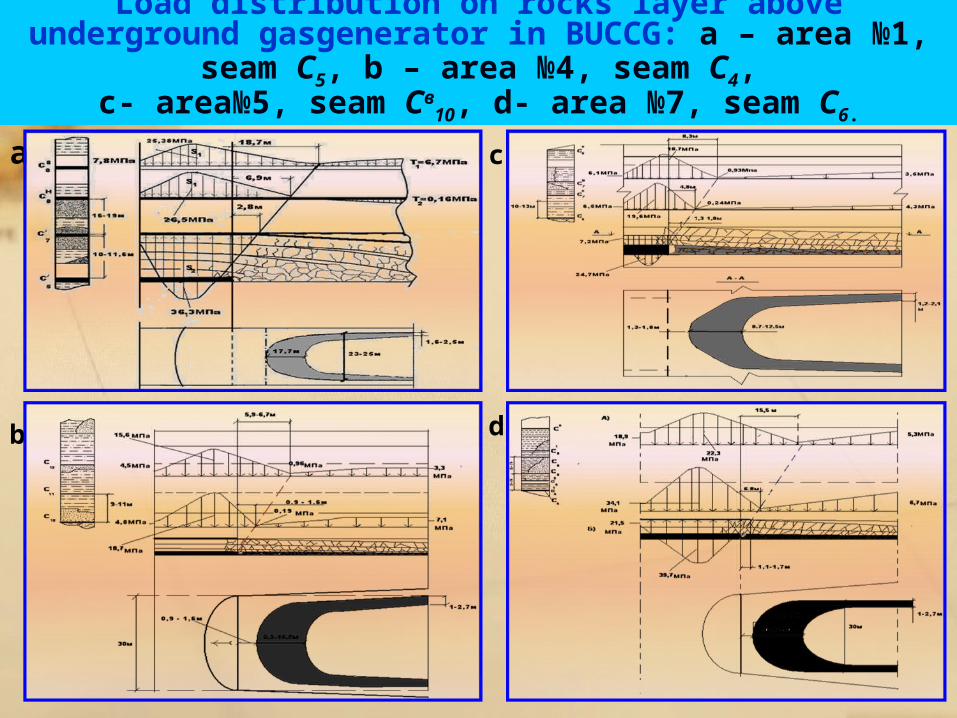
Load distribution on rocks layer above underground gasgenerator in BUCCG: а – area №1, seam С5, b – area №4, seam С4,
c- area№5, seam Св10, d- area №7, seam С6.a
b
c
d
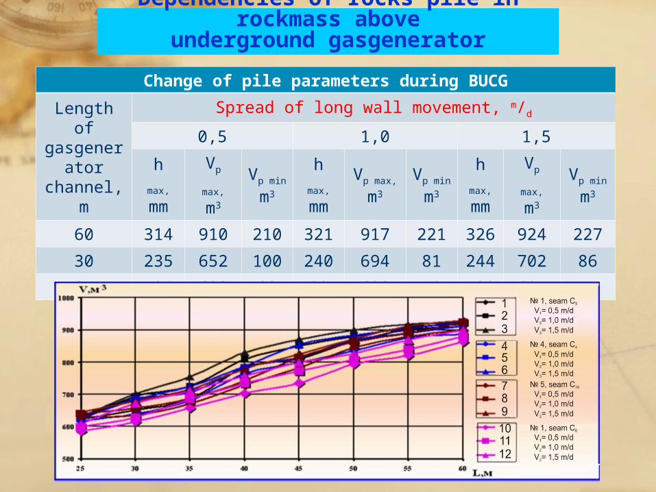
Dependencies of rocks pile in rockmass aboveunderground gasgenerator
Change of pile parameters during BUCG
Length of gasgener
ator channel,
m
Spread of long wall movement, m/d
0,5 1,0 1,5
h max,
mm
Vp
max,
m3
Vp
min
m3
h max,
mm
Vp max,
m3
Vp
min
m3
h max,
mm
Vp
max,
m3
Vp min
m3
60 314 910 210 321 917 221 326 924 227
30 235 652 100 240 694 81 244 702 86
25 194 623 89 89 628 72 180 631 75
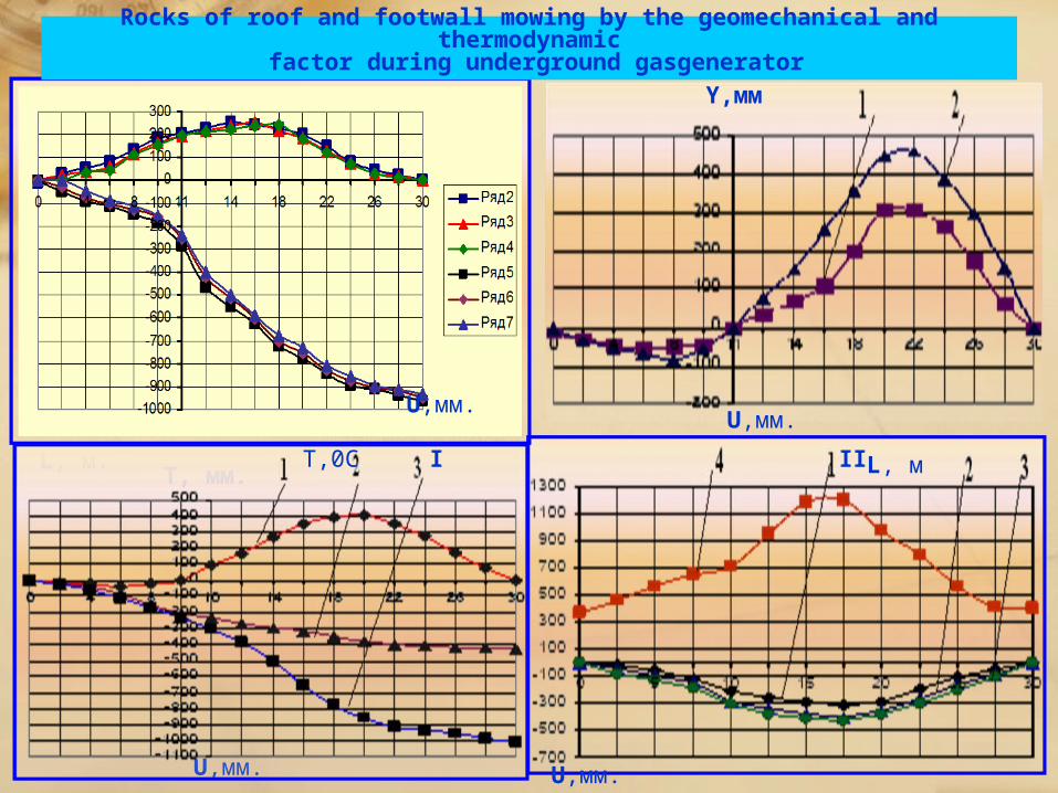
Rocks of roof and footwall mowing by the geomechanical and thermodynamic factor during underground gasgenerator
U,мм. L, м.
Т, мм.
Y,мм
U,мм. L, м
Т,0С I II III
U,мм. L, м
U,мм. L, м
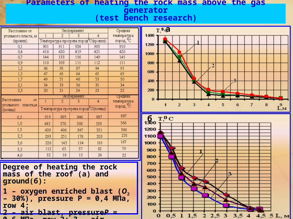
Parameters of heating the rock mass above the gas generator
(test bench research) а
б
Degree of heating the rock mass of the roof (а) and ground(б):1 – oxygen enriched blast (О2 – 30%), pressure P = 0,4 МПа, row 4; 2 – air blast, pressureР = 0,6 МПа, row 2; 3 – air blast, pressure Р = 0,4 МПа.
Recommended