1
15 LD 22515 LD 31515 LD 35015 LD 40015 LD 440
DATE
22.12.2003
COMPILER TECO/ATI REG. CODE
1-5302-467
MODEL N°
50707
DATE OF ISSUE
06-95REVISION 05
ENDORSED
6th Edition
WORK SHOPMANUAL
15LD series engines, p.no. 1-5302-467
FOREWORD
We have done all in our power to give up to date and accurate technical information in this manual. Lombardiniengines are, however, constantly developing thus the data in this publication may be liable to modification withoutprior notice.
The information in this manual is the exclusive property of Lombardini. Neither partial nor total duplications or reprintsare therefore permitted without the express authorization of Lombardini.
The information in this manual is given on the assumption that:
1- the persons who service Lombardini engines have been adequately trained and outfitted to safely and professionallycarry out the necessary tasks;
2- the persons who service Lombardini engines possess the necessary skills and special Lombardini tools to safelyand professionally carry out the necessary tasks;
3- the persons who service Lombardini engines have read the specific information concerning the above mentionedService operations and that they have clearly understood the operations required.
GENERAL SERVICE NOTES
1 - Only use genuine Lombardini spare parts. Use of spurious spares may lead to incorrect performance and shortenthe life of the engines.
2 - The metric system is used to express all data, i.e. the dimensions are given in millimeters (mm), torque isexpressed in Newton-meters (Nm), weight in kilograms (Kg), volume in liters or cubic centimeters (cc) andpressure in barometric units (bar).
3DATE
22.12.2003
COMPILER TECO/ATI REG. CODE
1-5302-467
MODEL N°
50707
DATE OF ISSUE
06-95REVISION 05
ENDORSED
WARRANTY CERTIFICATE
WARRANTY CERTIFICATE
The products manufactured by Lombardini Srl are warranted to be free from conformity defects for a period of 24months from the date of delivery to the first end user.For engines fitted to stationary equipment, working at constant load and at constant and/or slightly variable speedwithin the setting limits, the warranty covers a period up to a limit of 2000 working hours, if the above mentionedperiod (24 months) is not expired.If no hour-meter is fitted , 12 working hours per calendar day will be considered.For what concerns the parts subject to wear and deterioration (injection/feeding system, electrical system, coolingsystem, sealing parts, non-metallic pipes, belts) warranty covers a maximum limit of 2000 working hours, if theabove mentioned period (24 months) is not expired.For correct maintenance and replacement of these parts, it is necessary to follow the instructions reported in thedocumentation supplied with each engine.To ensure the engine warranty is valid, the engine installation, considering the product technical features, must becarried out by qualified personnel only.The list of the Lombardini authorized dealers is reported in the “Service” booklet, supplied with each engine.Special applications involving considerable modifications to the cooling/lubricating system (for ex.: dry oil sump),filtering system, turbo-charged models, will require special written warranty agreements.Within the above stated periods Lombardini Srl directly or through its authorized network will repair and/or replacefree of charge any own part or component that, upon examination by Lombardini or by an authorized Lombardiniagent, is found to be defective in conformity, workmanship or materials.Any other responsibility/obligation for different expenses, damages and direct/indirect losses deriving from the engineuse or from both the total or partial impossibility of use, is excluded.The repair or replacement of any component will not extend or renew the warranty period.
Lombardini warranty obligations here above described will be cancelled if:
- Lombardini engines are not correctly installed and as a consequence the correct functional parameters are notrespected and altered.
- Lombardini engines are not used according to the instructions reported in the “Use and Maintenance” bookletsupplied with each engine.
- Any seal affixed to the engine by Lombardini has been tampered with or removed.- Spare parts used are not original Lombardini.- Feeding and injection systems are damaged by unauthorized or poor quality fuel types.- Electrical system failure is due to components, connected to this system, which are not supplied or installed by
Lombardini.- Engines have been disassembled, repaired or altered by any part other than an authorized Lombardini agent.
Following expiration of the above stated warranty periods and working hours, Lombardini will have no furtherresponsibility for warranty and will consider its here above mentioned obligations for warranty complete.Any warranty request related to a non-conformity of the product must be addressed to the Lombardini Srl serviceagents.
4DATE
22.12.2003
COMPILER TECO/ATI REG. CODE
1-5302-467
MODEL N°
50707
DATE OF ISSUE
06-95REVISION 05
ENDORSED
This manual contains pertinent information regarding the repair of LOMBARDINI water-cooled,indirect injection Diesel engines type 15LD225, 15LD315, 15LD350, 15LD400, 15LD440:updated November 15, 2003.
○ ○ ○ ○ ○ ○ ○ ○ ○ ○ ○ ○ ○ ○ ○ ○ ○ ○ ○ ○ ○ ○ ○ ○ ○ ○ ○ ○ ○ ○ ○ ○ ○ ○ ○ ○ ○ ○ ○ ○ ○ ○ ○ ○ ○ ○
○ ○ ○ ○ ○ ○ ○ ○ ○ ○ ○ ○ ○ ○ ○ ○ ○ ○ ○ ○ ○ ○ ○ ○ ○ ○ ○ ○ ○ ○ ○ ○ ○ ○ ○ ○ ○ ○ ○ ○ ○ ○ ○ ○ ○ ○ ○ ○
○ ○ ○ ○ ○ ○ ○ ○ ○ ○ ○ ○ ○ ○ ○ ○ ○ ○ ○ ○ ○ ○ ○ ○ ○ ○ ○ ○ ○ ○ ○ ○ ○ ○ ○ ○ ○ ○ ○ ○ ○ ○ ○ ○ ○ ○ ○ ○ ○ ○
○ ○ ○ ○ ○ ○ ○ ○ ○ ○ ○ ○ ○ ○ ○ ○ ○ ○ ○ ○ ○ ○ ○ ○ ○ ○ ○ ○ ○ ○ ○ ○ ○ ○ ○ ○ ○ ○ ○ ○ ○ ○ ○ ○ ○ ○ ○ ○ ○ ○ ○ ○ ○ ○
○ ○ ○ ○ ○ ○ ○ ○ ○ ○ ○ ○ ○ ○ ○ ○ ○ ○ ○ ○ ○ ○ ○ ○ ○ ○ ○ ○ ○ ○ ○ ○ ○ ○ ○ ○ ○ ○ ○ ○ ○ ○ ○
○ ○ ○ ○ ○ ○ ○ ○ ○ ○ ○ ○ ○ ○ ○ ○ ○ ○ ○ ○ ○ ○ ○ ○ ○ ○ ○ ○ ○ ○ ○ ○ ○ ○ ○ ○ ○ ○ ○ ○ ○ ○ ○ ○ ○ ○ ○ ○ ○ ○
○ ○ ○ ○ ○ ○ ○ ○ ○ ○ ○ ○ ○ ○ ○ ○ ○ ○ ○ ○ ○ ○ ○ ○ ○ ○ ○ ○ ○ ○ ○ ○ ○ ○ ○ ○ ○ ○ ○ ○ ○ ○ ○ ○ ○
○ ○ ○ ○ ○ ○ ○ ○ ○ ○ ○ ○ ○ ○ ○ ○ ○ ○ ○ ○ ○ ○ ○ ○ ○ ○ ○ ○ ○ ○ ○ ○ ○ ○ ○ ○ ○ ○ ○ ○ ○ ○ ○ ○ ○ ○ ○ ○ ○ ○ ○ ○
○ ○ ○ ○ ○ ○ ○ ○ ○ ○ ○ ○ ○ ○ ○ ○ ○ ○ ○ ○ ○ ○ ○ ○ ○ ○ ○ ○ ○ ○ ○ ○ ○ ○ ○ ○ ○ ○ ○ ○ ○ ○ ○ ○ ○ ○ ○ ○ ○ ○ ○
○ ○ ○ ○ ○ ○ ○ ○ ○ ○ ○ ○ ○ ○ ○ ○ ○ ○ ○ ○ ○ ○ ○ ○ ○ ○ ○ ○ ○ ○ ○ ○ ○ ○ ○ ○ ○ ○ ○ ○ ○ ○ ○ ○ ○
○ ○ ○ ○ ○ ○ ○ ○ ○ ○ ○ ○ ○ ○ ○ ○ ○ ○ ○ ○ ○ ○ ○ ○ ○ ○ ○ ○ ○ ○ ○ ○ ○ ○ ○ ○ ○ ○ ○ ○ ○ ○ ○ ○ ○ ○
○ ○ ○ ○ ○ ○ ○ ○ ○ ○ ○ ○ ○ ○ ○ ○ ○ ○ ○ ○ ○ ○ ○ ○ ○ ○ ○ ○ ○ ○ ○ ○ ○ ○ ○ ○ ○ ○ ○ ○ ○
○ ○ ○ ○ ○ ○ ○ ○ ○ ○ ○ ○ ○ ○ ○ ○ ○ ○ ○ ○ ○ ○ ○ ○ ○ ○ ○ ○ ○ ○ ○ ○ ○ ○ ○ ○ ○ ○ ○ ○ ○ ○ ○ ○ ○ ○ ○ ○ ○
○ ○ ○ ○ ○ ○ ○ ○ ○ ○ ○ ○ ○ ○ ○ ○ ○ ○ ○ ○ ○ ○ ○ ○ ○ ○ ○ ○ ○ ○ ○ ○ ○ ○ ○ ○ ○ ○ ○ ○ ○ ○ ○ ○ ○ ○ ○ ○ ○
○ ○ ○ ○ ○ ○ ○ ○ ○ ○ ○ ○ ○ ○ ○ ○ ○ ○ ○ ○ ○ ○ ○ ○ ○ ○ ○ ○ ○ ○ ○ ○ ○ ○ ○ ○ ○ ○ ○ ○ ○ ○ ○ ○ ○ ○ ○ ○ ○ ○ ○ ○
○ ○ ○ ○ ○ ○ ○ ○ ○ ○ ○ ○ ○ ○ ○ ○ ○ ○ ○ ○ ○ ○ ○ ○ ○ ○ ○ ○ ○ ○ ○ ○ ○ ○ ○ ○ ○ ○ ○ ○ ○ ○ ○ ○ ○ ○ ○ ○ ○ ○ ○ ○ ○ ○ ○
○ ○ ○ ○ ○ ○ ○ ○ ○ ○ ○ ○ ○ ○ ○ ○ ○ ○ ○ ○ ○ ○ ○ ○ ○
○ ○ ○ ○ ○ ○ ○ ○ ○ ○ ○ ○ ○ ○ ○ ○ ○ ○ ○ ○ ○ ○ ○ ○ ○ ○ ○ ○ ○ ○ ○ ○ ○ ○
○ ○ ○ ○ ○ ○ ○ ○ ○ ○ ○ ○ ○ ○ ○ ○ ○ ○ ○ ○ ○ ○ ○ ○ ○ ○ ○ ○ ○ ○ ○ ○ ○ ○ ○ ○ ○
○ ○ ○ ○ ○ ○ ○ ○ ○ ○ ○ ○ ○ ○ ○ ○ ○ ○ ○ ○ ○ ○ ○ ○ ○ ○ ○ ○ ○ ○ ○ ○ ○ ○ ○ ○ ○ ○ ○ ○ ○ ○ ○ ○ ○ ○ ○
○ ○ ○ ○ ○ ○ ○ ○ ○ ○ ○ ○ ○ ○ ○ ○ ○ ○ ○ ○ ○ ○ ○ ○ ○ ○ ○ ○ ○ ○ ○ ○ ○ ○ ○ ○ ○ ○ ○ ○ ○ ○ ○ ○ ○ ○ ○ ○ ○ ○ ○ ○ ○ ○
○ ○ ○ ○ ○ ○ ○ ○ ○ ○ ○ ○
INDEX
TABLE OF CONTENTS
I TROUBLESHOOTING
II SAFETY DECALS - SAFETY INSTRUCTIONS
III MODEL NUMBER AND IDENTIFICATION
IV TECHNICAL DATA
V CHARACTERISTIC CURVES
VI OVERALL DIMENSIONS
VII MAINTENANCE- RECOMMENDED OIL TYPE - REFILLING
VIII DISASSEMBLY / REASSEMBLY
Automatic decompressionAvailability of bearingsCam height (mm)CamshaftCamshaft – Antireverse systemCamshaft end playCamshaft journals and boreCamshaft timingClearanceConnecting rodConnecting rod alignementConnecting rod, piston pinCrankshaft - journal diameter (mm)Crankshaft end playCylinderCylinder headCylinder roughnessDimensions and clearance between guides and valve stems (mm)Dimensions of camshaft journals and bore (mm)Dimensions of pistons and cylinders, LogoDinamic balancer timingDrive shaft - Main bearing inside diameter, connecting rod big end, crankshaft bearing and timingcontrol gear and balancer - Clearance and interference between the corresponding journalsDrive shaft oil sealsDrive shaft, connection radiusDrive shaft, lubrication ducts, bore thread on flywheel side and p.t.o.Drive shaft, main journal/crankpin diameter, gear cover bearing inside diameter on timing sideDry air cleaner for 15LD 225Dry air cleaner for 15LD 315 and 15 LD 350Dry air cleaner for 15LD 400-440Dynamic balancer (on request)FlywheelFuel filter 15 LD 225-400-440 (version with internal filter)Fuel filter for 15 LD 225 - 315 - 350 - 400 - 440 (version with external filter)Hydraulic tappets 15 LD 400-440Injector projectionMufflerOil-bath air cleaner (optional)
Page 7
" 8-9
" 11
" 12-13
" 14-15
" 16-17
" 18-19
Page 20
413839394041394034363636383631273130393143
38373737372020214126252524272222
○ ○ ○ ○ ○ ○ ○ ○ ○ ○ ○ ○ ○ ○ ○ ○ ○ ○ ○ ○ ○ ○ ○ ○ ○ ○ ○ ○ ○ ○ ○ ○ ○ ○ ○ ○ ○ ○ ○ ○ ○ ○ ○ ○ ○ ○ ○ ○ ○
○ ○ ○ ○ ○ ○ ○ ○ ○ ○ ○ ○ ○ ○ ○ ○ ○ ○ ○ ○ ○ ○ ○ ○ ○ ○ ○ ○ ○ ○ ○ ○ ○ ○ ○ ○ ○ ○ ○ ○ ○ ○ ○ ○
○ ○ ○ ○ ○ ○ ○ ○ ○ ○ ○ ○ ○ ○ ○ ○ ○ ○ ○ ○ ○ ○ ○ ○
○ ○ ○ ○ ○ ○ ○ ○ ○ ○
○ ○ ○ ○ ○ ○ ○ ○ ○ ○ ○ ○ ○ ○ ○ ○ ○ ○ ○ ○ ○ ○ ○ ○ ○ ○ ○ ○ ○ ○ ○ ○ ○ ○ ○ ○ ○ ○ ○ ○ ○ ○ ○ ○
○ ○ ○ ○ ○ ○ ○ ○ ○ ○ ○ ○ ○ ○ ○ ○ ○ ○ ○ ○ ○ ○ ○ ○ ○ ○ ○ ○ ○ ○ ○ ○ ○ ○ ○ ○ ○ ○ ○ ○ ○ ○ ○
○ ○ ○ ○ ○ ○ ○ ○ ○ ○ ○ ○ ○ ○ ○ ○ ○ ○ ○ ○ ○ ○ ○ ○ ○ ○ ○ ○ ○ ○ ○ ○ ○ ○ ○ ○ ○
○ ○ ○ ○ ○ ○ ○ ○ ○ ○ ○ ○ ○ ○ ○ ○ ○ ○ ○ ○ ○ ○ ○ ○ ○ ○ ○ ○ ○ ○ ○ ○ ○ ○ ○ ○ ○ ○ ○ ○ ○ ○ ○ ○ ○
○ ○ ○ ○ ○ ○ ○ ○ ○ ○ ○ ○ ○ ○ ○ ○ ○ ○ ○ ○ ○ ○ ○ ○ ○ ○ ○ ○ ○ ○ ○ ○ ○ ○ ○ ○ ○ ○ ○ ○ ○ ○ ○ ○ ○ ○ ○ ○ ○ ○
○ ○ ○ ○ ○ ○ ○ ○ ○ ○ ○ ○ ○ ○ ○ ○ ○ ○ ○ ○ ○ ○ ○ ○ ○ ○ ○ ○ ○ ○ ○ ○ ○ ○ ○ ○ ○ ○ ○ ○ ○ ○ ○
○ ○ ○ ○ ○ ○ ○ ○ ○ ○ ○ ○ ○ ○ ○ ○ ○ ○ ○ ○ ○
○ ○ ○ ○ ○ ○ ○ ○ ○ ○ ○ ○ ○ ○ ○ ○ ○ ○ ○ ○ ○ ○ ○ ○ ○ ○ ○ ○ ○ ○
○ ○ ○ ○ ○ ○ ○ ○ ○ ○ ○ ○ ○ ○ ○ ○ ○ ○ ○ ○ ○ ○ ○ ○ ○ ○ ○ ○ ○ ○ ○ ○ ○ ○ ○ ○ ○ ○ ○ ○ ○ ○ ○ ○ ○ ○ ○ ○ ○ ○ ○ ○ ○ ○ ○
○ ○ ○ ○ ○ ○ ○ ○ ○ ○ ○ ○ ○ ○ ○ ○ ○ ○ ○ ○ ○ ○ ○ ○ ○ ○ ○ ○ ○ ○ ○ ○ ○ ○ ○ ○ ○ ○ ○ ○ ○ ○ ○ ○
○ ○ ○ ○ ○ ○ ○ ○ ○ ○ ○ ○ ○ ○ ○ ○ ○ ○ ○ ○ ○ ○ ○ ○ ○ ○ ○ ○ ○ ○ ○ ○ ○ ○ ○ ○ ○ ○ ○ ○ ○ ○ ○ ○ ○ ○ ○ ○ ○ ○ ○ ○ ○ ○ ○ ○
5DATE
22.12.2003
COMPILER TECO/ATI REG. CODE
1-5302-467
MODEL N°
50707
DATE OF ISSUE
06-95REVISION 05
ENDORSED
○ ○ ○ ○ ○ ○ ○ ○ ○ ○ ○ ○ ○ ○ ○ ○ ○ ○ ○ ○ ○ ○ ○ ○ ○ ○ ○ ○ ○ ○ ○ ○ ○ ○ ○ ○ ○ ○ ○ ○ ○ ○ ○ ○ ○ ○ ○ ○ ○ ○
○ ○ ○ ○ ○ ○ ○ ○ ○ ○ ○ ○ ○ ○ ○ ○ ○ ○ ○ ○ ○ ○ ○ ○ ○ ○ ○ ○ ○ ○ ○ ○ ○ ○ ○ ○ ○ ○ ○ ○ ○ ○ ○ ○ ○ ○ ○ ○ ○ ○
○ ○ ○ ○ ○ ○ ○ ○ ○ ○ ○ ○ ○ ○ ○ ○ ○ ○ ○ ○ ○ ○ ○ ○ ○ ○ ○ ○ ○ ○ ○ ○ ○ ○ ○ ○ ○ ○ ○ ○ ○ ○ ○ ○ ○ ○ ○
○ ○ ○ ○ ○ ○ ○ ○ ○ ○ ○ ○ ○ ○ ○ ○ ○ ○ ○ ○ ○ ○ ○ ○ ○ ○ ○ ○ ○ ○ ○ ○ ○ ○ ○ ○ ○ ○ ○ ○ ○ ○ ○ ○
○ ○ ○ ○ ○ ○ ○ ○ ○ ○ ○ ○ ○ ○ ○ ○ ○ ○ ○ ○ ○ ○ ○ ○ ○ ○ ○ ○ ○ ○ ○ ○ ○ ○ ○ ○
○ ○ ○ ○ ○ ○ ○ ○ ○ ○ ○ ○ ○ ○ ○ ○ ○ ○ ○ ○ ○ ○ ○ ○ ○ ○ ○ ○ ○ ○ ○ ○ ○ ○ ○ ○ ○
○ ○ ○ ○ ○ ○ ○ ○ ○ ○ ○ ○ ○ ○ ○ ○ ○ ○ ○ ○ ○ ○ ○ ○ ○ ○ ○ ○ ○ ○ ○ ○ ○ ○ ○ ○ ○ ○ ○ ○ ○ ○ ○ ○ ○ ○ ○
○ ○ ○ ○ ○ ○ ○ ○ ○ ○ ○ ○ ○ ○ ○ ○ ○ ○ ○ ○ ○ ○ ○ ○ ○ ○ ○ ○ ○ ○ ○ ○ ○ ○ ○ ○ ○ ○
○ ○ ○ ○ ○ ○ ○ ○ ○ ○ ○ ○ ○ ○ ○ ○ ○ ○ ○ ○ ○ ○ ○ ○ ○ ○ ○ ○ ○ ○ ○ ○ ○ ○ ○ ○ ○ ○ ○ ○ ○ ○ ○ ○ ○ ○ ○ ○ ○ ○ ○
○ ○ ○ ○ ○ ○ ○ ○ ○ ○ ○ ○ ○ ○ ○ ○ ○ ○ ○ ○ ○ ○ ○ ○ ○ ○ ○ ○ ○ ○ ○ ○ ○ ○ ○ ○ ○ ○ ○ ○ ○
○ ○ ○ ○ ○ ○ ○ ○ ○ ○ ○ ○ ○ ○ ○ ○ ○ ○ ○ ○ ○ ○ ○ ○ ○ ○ ○ ○ ○ ○ ○ ○ ○ ○ ○ ○ ○ ○ ○ ○ ○ ○ ○ ○ ○ ○ ○ ○ ○ ○ ○ ○ ○ ○ ○
○ ○ ○ ○ ○ ○ ○ ○ ○ ○ ○ ○ ○ ○ ○ ○ ○ ○ ○ ○ ○ ○ ○ ○ ○ ○ ○ ○ ○ ○ ○ ○ ○ ○ ○ ○ ○ ○ ○ ○ ○ ○ ○ ○ ○ ○ ○ ○ ○ ○ ○
○ ○ ○ ○ ○ ○ ○ ○ ○ ○ ○ ○ ○ ○ ○ ○ ○ ○ ○ ○ ○ ○ ○ ○ ○ ○ ○ ○ ○ ○ ○ ○ ○ ○ ○ ○ ○ ○ ○ ○ ○ ○ ○ ○ ○ ○
○ ○ ○ ○ ○ ○ ○ ○ ○ ○ ○ ○ ○ ○ ○ ○ ○ ○ ○ ○ ○ ○ ○ ○ ○ ○ ○ ○ ○ ○ ○ ○ ○ ○ ○ ○
○ ○ ○ ○ ○ ○ ○ ○ ○ ○ ○ ○ ○ ○ ○ ○ ○ ○ ○ ○ ○ ○ ○ ○ ○ ○ ○ ○ ○ ○ ○ ○ ○
○ ○ ○ ○ ○ ○ ○ ○ ○ ○ ○ ○ ○ ○ ○ ○ ○ ○ ○ ○ ○ ○ ○ ○ ○ ○ ○ ○ ○ ○ ○ ○ ○ ○ ○ ○ ○ ○ ○ ○ ○ ○ ○ ○ ○ ○ ○ ○ ○ ○ ○ ○ ○ ○ ○ ○ ○
○ ○ ○ ○ ○ ○ ○ ○ ○ ○ ○ ○ ○ ○ ○ ○ ○ ○ ○ ○ ○ ○ ○ ○ ○ ○ ○ ○ ○ ○ ○ ○ ○ ○ ○ ○ ○ ○ ○ ○ ○ ○ ○ ○ ○ ○ ○ ○ ○ ○
○ ○ ○ ○ ○ ○ ○ ○ ○ ○ ○ ○ ○ ○ ○ ○ ○ ○ ○ ○ ○ ○ ○ ○ ○ ○ ○ ○ ○ ○ ○ ○ ○ ○ ○ ○ ○ ○ ○ ○ ○ ○ ○ ○ ○ ○ ○ ○ ○
○ ○ ○ ○ ○ ○ ○ ○ ○ ○ ○ ○ ○ ○ ○ ○ ○ ○ ○ ○ ○ ○ ○ ○ ○ ○ ○ ○ ○ ○ ○ ○ ○ ○ ○ ○ ○ ○ ○ ○ ○ ○ ○ ○ ○ ○ ○ ○ ○ ○ ○ ○
○ ○ ○ ○ ○ ○ ○ ○ ○ ○ ○ ○ ○ ○ ○ ○ ○ ○ ○ ○ ○ ○ ○ ○ ○ ○ ○ ○ ○ ○ ○ ○ ○ ○ ○ ○ ○ ○ ○ ○ ○ ○ ○ ○ ○ ○ ○ ○
○ ○ ○ ○ ○ ○ ○ ○ ○ ○ ○ ○ ○ ○ ○ ○ ○ ○ ○ ○ ○ ○ ○ ○ ○ ○ ○ ○ ○ ○ ○ ○ ○ ○ ○ ○ ○ ○ ○ ○ ○
○ ○ ○ ○ ○ ○ ○ ○ ○ ○ ○ ○ ○ ○ ○ ○ ○ ○ ○ ○ ○ ○ ○ ○ ○ ○ ○ ○ ○ ○ ○ ○ ○ ○ ○ ○ ○ ○ ○ ○ ○ ○ ○
○ ○ ○ ○ ○ ○ ○ ○ ○ ○ ○ ○ ○ ○ ○ ○ ○ ○ ○ ○ ○ ○ ○ ○ ○ ○ ○ ○ ○ ○ ○ ○ ○ ○ ○ ○ ○ ○ ○ ○ ○ ○
○ ○ ○ ○ ○ ○ ○ ○ ○ ○ ○ ○ ○ ○ ○ ○ ○ ○ ○ ○ ○ ○ ○ ○ ○ ○ ○ ○ ○ ○ ○ ○ ○ ○ ○ ○ ○ ○ ○ ○ ○ ○ ○ ○ ○ ○ ○
○ ○ ○ ○ ○ ○ ○ ○ ○ ○ ○ ○ ○ ○ ○ ○ ○ ○ ○ ○ ○ ○ ○ ○ ○ ○ ○ ○ ○ ○ ○ ○ ○ ○ ○ ○ ○ ○ ○ ○ ○ ○ ○ ○ ○ ○ ○ ○
○ ○ ○ ○ ○ ○ ○ ○ ○ ○ ○ ○ ○ ○ ○ ○ ○ ○ ○ ○ ○ ○ ○ ○ ○ ○ ○ ○ ○ ○ ○ ○ ○
PistonPiston - RefittingPiston protrusion checkPiston rings, assembly orderPiston rings, distance between the tips (mm)Piston rings, play between the slots (mm)Prefilter for dry air filterRe-coil startingRefitting gear cover on timing sideRocker arm cover - Breather ricirculationRocker arm cover breather systemShroudSpeed governorSpeed governor removalTankTiming angles for inspection (0.65-0.70 valve play).Timing angles for operation (0.15 valve play).Valve seat lappingValve timing checkValve, springsValve/rocker arm clearance ( 15 LD 225-315-350 )Valves - DisassemblyValves - Oil seal in valve guideValves seats and valve seat boresValves, characteristicsValves, guide insertionValves, guides and housings
IX LUBRICATION SYSTEM
15 LD 225 - 315 - 350 LUBRICATION SYSTEM15 LD 400-440 LUBRICATION SYSTEMCalibratedInternal strainerOil filterOil pressure checkOil pressure curve at full speedOil pressure curve at idle speedOil pressure regulation valveOil pumpOil pump - Clearance between rotors
X FUEL SYSTEM
Feed pump (optional)Fuel filter 15 LD 225-315-350-400-440Fuel filter 15LD 225 (version with internal filter in tank)Fuel pump, drive rod protrusionFuelling/injection circuit for 15 LD 315-350-400-440Fuelling/injection circuit for 15LD 225Injection advance adjustmentInjection pumpInjection pump components and disassemblyInjection pump delivery check on test benchInjection pump fitting in the crankcaseInjection pump non-return valveInjection pump refittingInjection pump, body, plunger and delivery valveInjection pump, Rilsan tube refittingInjection pump, Rilsan tube removalInjectorInjector calibrationNozzlesReferences on the flywheelStatic injection lead test on flywheelStatic injection timing
Page 313435343334212645232226454525444430432823282830292929
Page 46
4647494849495050484848
Page 42
52525253515158535456535554545555585959575756
○ ○ ○ ○ ○ ○ ○ ○ ○ ○ ○ ○ ○ ○ ○ ○ ○ ○ ○ ○ ○ ○ ○ ○ ○ ○ ○ ○ ○ ○ ○ ○ ○ ○ ○
○ ○ ○ ○ ○ ○ ○ ○ ○ ○ ○ ○ ○ ○ ○ ○ ○ ○ ○ ○ ○ ○ ○ ○ ○ ○ ○ ○ ○ ○ ○ ○ ○ ○ ○ ○ ○ ○
○ ○ ○ ○ ○ ○ ○ ○ ○ ○ ○ ○ ○ ○ ○ ○ ○ ○ ○ ○ ○ ○ ○ ○ ○ ○ ○ ○ ○ ○ ○ ○ ○ ○ ○ ○ ○ ○ ○ ○ ○ ○ ○ ○ ○ ○ ○ ○ ○ ○ ○
○ ○ ○ ○ ○ ○ ○ ○ ○ ○ ○ ○ ○ ○ ○ ○ ○ ○ ○ ○ ○ ○ ○ ○ ○ ○ ○ ○ ○ ○ ○ ○ ○ ○ ○ ○ ○ ○ ○ ○ ○ ○ ○ ○ ○ ○ ○ ○ ○ ○ ○ ○ ○ ○ ○
○ ○ ○ ○ ○ ○ ○ ○ ○ ○ ○ ○ ○ ○ ○ ○ ○ ○ ○ ○ ○ ○ ○ ○ ○ ○ ○ ○ ○ ○ ○ ○ ○ ○ ○ ○ ○ ○ ○ ○ ○ ○ ○ ○ ○ ○ ○ ○ ○
○ ○ ○ ○ ○ ○ ○ ○ ○ ○ ○ ○ ○ ○ ○ ○ ○ ○ ○ ○ ○ ○ ○ ○ ○ ○ ○ ○ ○ ○ ○ ○ ○ ○ ○ ○ ○ ○ ○ ○ ○ ○ ○
○ ○ ○ ○ ○ ○ ○ ○ ○ ○ ○ ○ ○ ○ ○ ○ ○ ○ ○ ○ ○ ○ ○ ○ ○ ○ ○ ○ ○ ○ ○ ○ ○ ○ ○ ○ ○ ○ ○ ○ ○ ○ ○
○ ○ ○ ○ ○ ○ ○ ○ ○ ○ ○ ○ ○ ○ ○ ○ ○ ○ ○ ○ ○ ○ ○ ○ ○ ○ ○ ○ ○ ○ ○ ○ ○ ○ ○ ○ ○ ○ ○ ○ ○ ○ ○ ○ ○ ○ ○ ○ ○ ○ ○ ○ ○ ○
○ ○ ○ ○ ○ ○ ○ ○ ○ ○ ○ ○ ○ ○ ○ ○ ○ ○ ○ ○ ○ ○ ○ ○ ○ ○ ○ ○ ○ ○ ○ ○ ○ ○ ○ ○ ○ ○ ○ ○ ○ ○ ○ ○ ○ ○ ○ ○
○ ○ ○ ○ ○ ○ ○ ○ ○ ○ ○ ○ ○ ○ ○ ○ ○ ○ ○ ○ ○ ○ ○ ○ ○ ○ ○ ○ ○ ○ ○ ○ ○ ○ ○ ○ ○ ○ ○
○ ○ ○ ○ ○ ○ ○ ○ ○ ○ ○ ○ ○ ○ ○ ○ ○ ○ ○ ○ ○ ○ ○ ○ ○ ○ ○ ○ ○ ○ ○ ○ ○ ○ ○ ○ ○ ○ ○ ○ ○ ○ ○
○ ○ ○ ○ ○ ○ ○ ○ ○ ○ ○ ○ ○ ○ ○ ○ ○ ○ ○ ○ ○ ○ ○ ○ ○ ○ ○ ○ ○ ○ ○ ○
○ ○ ○ ○ ○ ○ ○ ○ ○ ○ ○ ○ ○ ○ ○ ○ ○ ○ ○ ○ ○ ○ ○ ○ ○ ○ ○ ○ ○ ○ ○ ○ ○ ○ ○ ○ ○ ○ ○ ○
○ ○ ○ ○ ○ ○ ○ ○ ○ ○ ○ ○ ○ ○ ○ ○ ○ ○ ○ ○ ○ ○ ○ ○ ○ ○ ○ ○ ○ ○ ○ ○ ○ ○ ○ ○ ○ ○ ○ ○ ○ ○ ○ ○ ○ ○ ○ ○ ○ ○ ○ ○
○ ○ ○ ○ ○ ○ ○ ○ ○ ○ ○ ○ ○ ○ ○ ○ ○ ○ ○ ○ ○ ○ ○ ○ ○ ○ ○ ○ ○ ○ ○ ○ ○ ○ ○ ○ ○ ○ ○ ○ ○ ○ ○ ○
○ ○ ○ ○ ○ ○ ○ ○ ○ ○ ○ ○ ○ ○ ○ ○ ○ ○ ○ ○ ○ ○ ○ ○ ○ ○ ○ ○ ○ ○ ○
○ ○ ○ ○ ○ ○ ○ ○ ○ ○ ○ ○ ○ ○ ○ ○ ○ ○ ○ ○ ○ ○ ○ ○ ○ ○ ○ ○ ○ ○ ○ ○ ○ ○ ○
○ ○ ○ ○ ○ ○ ○ ○ ○ ○ ○ ○ ○ ○ ○ ○ ○ ○ ○ ○ ○ ○ ○ ○ ○ ○ ○ ○ ○ ○ ○ ○ ○ ○ ○ ○ ○
○ ○ ○ ○ ○ ○ ○ ○ ○ ○ ○ ○ ○ ○ ○ ○ ○ ○ ○ ○ ○ ○ ○ ○ ○ ○ ○ ○ ○ ○ ○ ○ ○ ○ ○ ○ ○ ○ ○ ○ ○ ○ ○
○ ○ ○ ○ ○ ○ ○ ○ ○ ○ ○ ○ ○ ○ ○ ○ ○ ○ ○ ○ ○ ○ ○ ○ ○ ○ ○ ○ ○ ○ ○ ○ ○ ○ ○ ○ ○ ○ ○ ○ ○ ○ ○ ○ ○ ○ ○
○ ○ ○ ○ ○ ○ ○ ○ ○ ○ ○ ○ ○ ○ ○ ○ ○ ○ ○ ○ ○ ○ ○ ○ ○ ○ ○ ○ ○ ○ ○ ○ ○ ○
○ ○ ○ ○ ○ ○ ○ ○ ○ ○ ○ ○ ○ ○ ○ ○ ○ ○ ○ ○ ○ ○ ○ ○ ○ ○ ○ ○ ○ ○ ○ ○ ○ ○ ○ ○ ○ ○ ○
○ ○ ○ ○ ○ ○ ○ ○ ○ ○ ○ ○ ○ ○ ○ ○ ○ ○ ○ ○ ○ ○ ○ ○ ○ ○ ○ ○ ○ ○ ○ ○ ○ ○ ○ ○ ○ ○ ○ ○ ○ ○ ○ ○ ○ ○ ○ ○ ○ ○ ○ ○ ○ ○ ○
○ ○ ○ ○ ○ ○ ○ ○ ○ ○ ○ ○ ○ ○ ○ ○ ○ ○ ○ ○ ○ ○ ○ ○ ○ ○ ○ ○ ○ ○ ○ ○ ○ ○ ○ ○ ○ ○ ○ ○
○ ○ ○ ○ ○ ○ ○ ○ ○ ○ ○ ○ ○ ○ ○ ○ ○ ○ ○ ○ ○ ○ ○ ○ ○ ○ ○ ○ ○ ○ ○ ○ ○ ○ ○ ○ ○ ○ ○ ○ ○ ○ ○ ○ ○ ○ ○ ○ ○ ○
○ ○ ○ ○ ○ ○ ○ ○ ○ ○ ○ ○ ○ ○ ○ ○ ○ ○ ○ ○ ○ ○ ○ ○ ○ ○ ○ ○ ○ ○ ○ ○ ○ ○ ○ ○ ○ ○ ○ ○ ○ ○ ○ ○ ○ ○ ○ ○ ○ ○ ○ ○ ○ ○ ○
○ ○ ○ ○ ○ ○ ○ ○ ○ ○ ○ ○ ○ ○ ○ ○ ○ ○ ○ ○ ○ ○ ○ ○ ○ ○ ○ ○ ○ ○ ○ ○ ○ ○ ○ ○ ○ ○ ○ ○ ○
INDEX
○ ○ ○ ○ ○ ○ ○ ○ ○ ○ ○ ○ ○ ○ ○ ○ ○ ○ ○ ○ ○ ○ ○ ○ ○ ○ ○ ○ ○ ○ ○ ○ ○ ○ ○ ○ ○ ○ ○ ○ ○ ○ ○ ○
○ ○ ○ ○ ○ ○ ○ ○ ○ ○ ○ ○ ○ ○ ○ ○ ○ ○ ○ ○ ○ ○ ○ ○ ○ ○ ○ ○ ○ ○ ○ ○ ○ ○ ○ ○ ○ ○ ○ ○ ○ ○ ○ ○ ○
○ ○ ○ ○ ○ ○ ○ ○ ○ ○ ○ ○ ○ ○ ○ ○ ○ ○ ○ ○ ○ ○ ○ ○ ○ ○ ○ ○ ○ ○ ○ ○ ○ ○ ○ ○ ○ ○ ○ ○ ○ ○ ○ ○ ○ ○ ○ ○ ○ ○ ○ ○ ○ ○ ○
○ ○ ○ ○ ○ ○ ○ ○ ○ ○ ○ ○ ○ ○ ○ ○ ○ ○ ○ ○ ○ ○ ○ ○ ○ ○ ○ ○ ○ ○ ○ ○ ○ ○ ○ ○ ○ ○ ○ ○
○ ○ ○ ○ ○ ○ ○ ○ ○ ○ ○ ○ ○ ○ ○ ○ ○ ○ ○ ○ ○ ○ ○ ○ ○ ○ ○ ○ ○ ○ ○ ○ ○ ○ ○ ○ ○ ○ ○ ○ ○ ○ ○ ○ ○
○ ○ ○ ○ ○ ○ ○ ○ ○ ○ ○ ○ ○ ○ ○ ○ ○ ○ ○ ○ ○ ○ ○ ○ ○ ○ ○ ○ ○ ○ ○ ○ ○ ○ ○ ○ ○ ○ ○ ○ ○
○ ○ ○ ○ ○ ○ ○ ○ ○ ○ ○ ○ ○ ○ ○ ○ ○ ○ ○ ○ ○ ○ ○ ○ ○ ○ ○ ○ ○ ○ ○ ○ ○ ○ ○ ○ ○ ○ ○ ○ ○ ○ ○ ○ ○ ○ ○ ○
6DATE
22.12.2003
COMPILER TECO/ATI REG. CODE
1-5302-467
MODEL N°
50707
DATE OF ISSUE
06-95REVISION 05
ENDORSED
INDEX
○ ○ ○ ○ ○ ○ ○ ○ ○ ○ ○ ○ ○ ○ ○ ○ ○ ○ ○ ○ ○ ○ ○ ○ ○ ○ ○ ○ ○
○ ○ ○ ○ ○ ○ ○ ○ ○ ○ ○ ○ ○ ○ ○ ○ ○ ○ ○
○ ○ ○ ○ ○ ○ ○ ○ ○ ○ ○ ○ ○ ○ ○ ○ ○ ○ ○ ○ ○ ○ ○ ○ ○ ○ ○ ○ ○ ○ ○ ○ ○ ○ ○ ○ ○ ○ ○ ○ ○
○ ○ ○ ○ ○ ○ ○ ○ ○ ○ ○ ○ ○ ○ ○ ○ ○ ○ ○ ○ ○ ○ ○ ○ ○ ○ ○ ○ ○ ○ ○ ○ ○ ○ ○ ○
○ ○ ○ ○ ○ ○ ○ ○ ○ ○ ○ ○ ○ ○ ○ ○ ○ ○ ○ ○ ○ ○ ○ ○ ○ ○ ○ ○ ○ ○ ○ ○ ○ ○ ○ ○ ○
○ ○ ○ ○ ○ ○ ○ ○ ○ ○ ○ ○ ○ ○ ○ ○ ○ ○ ○ ○ ○ ○ ○ ○ ○ ○ ○ ○ ○ ○ ○ ○ ○ ○ ○ ○ ○ ○ ○ ○ ○ ○ ○ ○ ○ ○ ○ ○ ○ ○ ○ ○ ○ ○
○ ○ ○ ○ ○ ○ ○ ○ ○ ○ ○ ○ ○ ○ ○ ○ ○ ○ ○ ○ ○ ○ ○ ○ ○ ○ ○ ○ ○ ○ ○ ○ ○ ○ ○ ○ ○
○ ○ ○ ○ ○ ○ ○ ○ ○ ○ ○ ○ ○ ○ ○ ○ ○ ○ ○ ○ ○ ○ ○
○ ○ ○ ○ ○ ○ ○ ○ ○ ○ ○ ○ ○ ○ ○ ○ ○ ○ ○ ○ ○ ○ ○ ○ ○ ○
○ ○ ○ ○ ○ ○ ○
○ ○ ○ ○ ○ ○ ○ ○ ○ ○ ○ ○ ○ ○ ○ ○ ○ ○ ○ ○ ○ ○ ○ ○ ○ ○ ○ ○ ○ ○ ○ ○ ○ ○ ○ ○ ○ ○ ○ ○ ○ ○ ○ ○ ○ ○
○ ○ ○ ○ ○ ○ ○ ○ ○ ○ ○ ○ ○ ○ ○ ○ ○ ○ ○ ○ ○ ○ ○ ○ ○ ○ ○ ○ ○ ○ ○ ○ ○ ○ ○ ○ ○ ○ ○ ○ ○ ○ ○ ○ ○ ○ ○ ○ ○ ○ ○ ○
○ ○ ○ ○ ○ ○ ○ ○ ○ ○ ○ ○ ○ ○ ○ ○ ○ ○ ○ ○ ○ ○ ○ ○ ○ ○ ○ ○ ○ ○ ○ ○ ○ ○ ○
○ ○ ○ ○ ○ ○ ○ ○ ○ ○ ○ ○ ○ ○ ○ ○ ○ ○ ○ ○ ○ ○ ○ ○ ○ ○ ○ ○ ○ ○ ○ ○ ○ ○ ○ ○ ○ ○ ○ ○ ○ ○ ○ ○ ○ ○ ○ ○ ○ ○
○ ○ ○ ○ ○ ○ ○ ○ ○ ○ ○ ○ ○ ○ ○ ○ ○ ○ ○ ○ ○ ○ ○ ○ ○ ○ ○ ○ ○ ○ ○ ○ ○ ○ ○ ○ ○ ○ ○ ○ ○ ○
○ ○ ○ ○ ○ ○ ○ ○ ○ ○ ○ ○ ○ ○ ○ ○ ○ ○ ○ ○ ○ ○ ○ ○ ○ ○ ○ ○ ○ ○ ○ ○ ○ ○ ○ ○ ○ ○ ○ ○ ○ ○ ○ ○
○ ○ ○ ○ ○ ○ ○ ○ ○ ○ ○ ○ ○ ○ ○ ○ ○ ○ ○ ○ ○ ○ ○ ○ ○ ○ ○ ○ ○ ○ ○ ○
○ ○ ○ ○ ○ ○ ○ ○ ○ ○ ○ ○ ○ ○ ○ ○ ○ ○ ○ ○ ○ ○ ○ ○ ○ ○ ○ ○ ○ ○ ○ ○
○ ○ ○ ○ ○ ○ ○ ○ ○ ○ ○ ○ ○ ○ ○ ○ ○ ○ ○ ○ ○ ○ ○
○ ○ ○ ○ ○ ○ ○ ○ ○ ○ ○ ○ ○ ○ ○ ○ ○ ○ ○ ○ ○ ○ ○ ○ ○ ○ ○
○ ○ ○ ○ ○ ○ ○ ○ ○ ○ ○ ○ ○ ○ ○ ○ ○ ○ ○ ○ ○ ○ ○ ○ ○ ○ ○ ○ ○ ○ ○ ○ ○ ○ ○ ○ ○ ○ ○ ○ ○ ○ ○
○ ○ ○ ○ ○ ○ ○ ○ ○ ○ ○ ○ ○ ○ ○ ○ ○ ○ ○ ○ ○ ○ ○ ○ ○ ○ ○ ○ ○
○ ○ ○ ○ ○ ○ ○ ○ ○ ○ ○ ○ ○ ○ ○ ○ ○ ○ ○ ○ ○ ○ ○ ○ ○ ○ ○ ○ ○ ○ ○ ○ ○ ○ ○ ○ ○ ○ ○ ○
○ ○ ○ ○ ○ ○ ○ ○ ○ ○ ○ ○ ○ ○ ○ ○ ○ ○ ○ ○ ○ ○ ○ ○ ○ ○ ○ ○ ○ ○ ○ ○ ○ ○ ○
XI ELECTRICAL SYSTEM
12V electric ignition layout with motor protection (optional)12V electric starter diagram with voltage regulator built into the ignition panel12V, 12A electric ignition diagram12V, 30A alternator battery recharging curve24V, 9A alternator battery recharging curveAlternatorAlternator battery charger graph (12V, 12A)Characteristic curves for starting motor type DW (L) 12V, 1.1 KWCharacteristic curves of Bosch starter motor type DW (L) 12V, 0.9 kWCharacteristic curves of Bosch starter motor type DW (L) 24V, 1.6 kWDiagram of electric starter motor protection with sole self-winding starter - without battery - (optional)Ignition switch positionsStarting motorTesting voltage regulator for proper operationVoltage regulator
XII SETTINGS ADJUSTEMENTS
ADJUSTMENTS - 15 LD 315-350ADJUSTMENTS - 15 LD 225Full speed setting in no-load conditions (standard)Idle speed adjustment, for small car versionsIdling speed setting in no-load conditions (standard)Injection pump delivery limiting and torque adapter (standard)Injection pump delivery settingInjection pump flow rate adjustment for 15LD 225-315-350No-load idling adjustment (standard)No-load top rate adjustment (standard)
XIII STORAGE
Temporary protection (1/6 months)Permanent protection (over 6 months)How to prepare the engine for operation
XIV TORQUE SPECIFICATIONS
Main torque specificationsUse of sealant
XV TORQUE SPECIFICATIONS
Standard bolt torque specifications
Page 61
636361626261616566666466656562
Page 67
67686767676869686868
Page 70
707070
Page 71
7171
Page 72
72
○ ○ ○ ○ ○ ○ ○ ○ ○ ○ ○ ○ ○ ○ ○ ○ ○ ○ ○ ○ ○ ○ ○ ○ ○ ○ ○ ○ ○ ○ ○ ○ ○ ○ ○ ○ ○ ○
○ ○ ○ ○ ○ ○ ○ ○ ○ ○ ○ ○ ○ ○ ○ ○ ○ ○ ○ ○ ○ ○ ○ ○ ○ ○ ○ ○ ○ ○ ○ ○ ○ ○ ○ ○ ○ ○ ○
○ ○ ○ ○ ○ ○ ○ ○ ○ ○ ○ ○ ○ ○ ○ ○ ○ ○ ○ ○ ○ ○ ○ ○ ○ ○ ○ ○ ○ ○ ○ ○ ○ ○ ○ ○ ○ ○ ○
○ ○ ○ ○ ○ ○ ○ ○ ○ ○ ○ ○ ○ ○ ○ ○ ○ ○ ○ ○ ○ ○ ○ ○ ○ ○ ○ ○ ○ ○ ○ ○ ○ ○ ○ ○ ○ ○ ○ ○ ○
○ ○ ○ ○ ○ ○ ○ ○ ○ ○ ○ ○ ○ ○ ○ ○ ○ ○ ○ ○ ○ ○ ○ ○ ○ ○ ○ ○ ○ ○ ○ ○ ○ ○ ○ ○ ○ ○ ○ ○ ○ ○ ○ ○ ○ ○
○ ○ ○ ○ ○ ○ ○ ○ ○ ○ ○ ○ ○ ○ ○ ○ ○ ○ ○ ○ ○ ○ ○ ○ ○ ○ ○ ○ ○ ○ ○ ○ ○ ○ ○ ○ ○ ○ ○ ○ ○ ○ ○ ○ ○ ○ ○ ○ ○ ○ ○ ○
○ ○ ○ ○ ○ ○ ○ ○ ○ ○ ○ ○ ○ ○ ○ ○ ○ ○ ○ ○ ○ ○ ○ ○ ○ ○ ○ ○ ○ ○ ○ ○ ○ ○ ○ ○ ○ ○ ○ ○ ○
7DATE
22.12.2003
COMPILER TECO/ATI REG. CODE
1-5302-467
MODEL N°
50707
DATE OF ISSUE
06-95REVISION 05
ENDORSED
ITROUBLE SHOOTING
Clogged pipesClogged fuel filterAir inside fuel circuitClogged tank breather holeFaulty fuel pumpInjector jammedJammed injection pump delivery valveWrong injector settingExcessive plunger blow-byJammed injection pump delivery controlWrong injection pump settingOil level too highJammed pressure relief valveWorn oil pumpAir inside oil suction pipeFaulty pressure gauge or switchClogged oil suction pipeBattery dischargedWrong or inefficient cable connectionDefective ignition switchDefective starter motorClogged air filterExcessive idle operationIncomplete running-inEngine overloadedAdvanced injectionDelayed injectionIncorrect governor linkage adjustmentBroken or loose governor springIdle speed too lowWorn or jammed piston ringsWorn or scored cylindersWorn valve guidesJammed valvesWorn bearingsGovernor linkage not free to slideDrive shaft not free to slideDamaged cylinder head gasket
TROUBLE
LUB
RIC
ATI
ON
POSSIBLE CAUSE
FUE
L C
IRC
UIT
ELE
CTR
ICS
YS
TEM
MA
INTE
-N
AN
CE
SE
TTIN
GS
/RE
PA
IRS
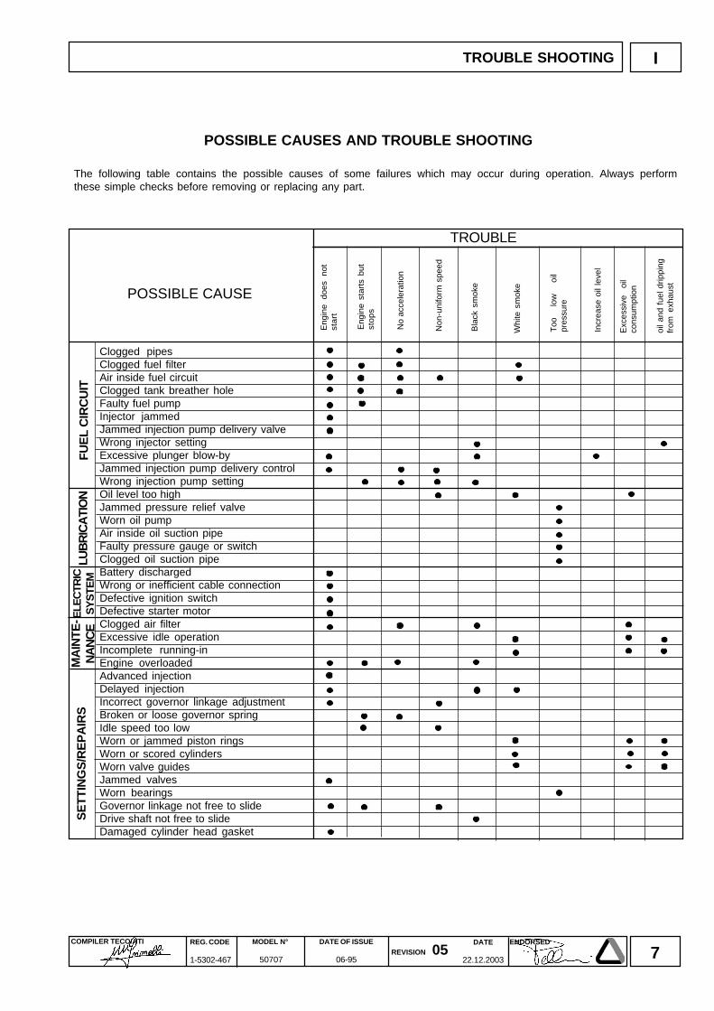
POSSIBLE CAUSES AND TROUBLE SHOOTING
The following table contains the possible causes of some failures which may occur during operation. Always performthese simple checks before removing or replacing any part.
Eng
ine
does
no
tst
art
No
acce
lera
tion
Bla
ck s
mok
e
Exc
essi
ve
oil
cons
umpt
ion
Too
lo
w
oil
pres
sure
Eng
ine
star
ts b
utst
ops
Non
-uni
form
spe
ed
Whi
te s
mok
e
oil a
nd f
uel d
rippi
ngfr
om e
xhau
st
Incr
ease
oil
leve
l
8DATE
22.12.2003
COMPILER TECO/ATI REG. CODE
1-5302-467
MODEL N°
50707
DATE OF ISSUE
06-95REVISION 05
ENDORSED
II
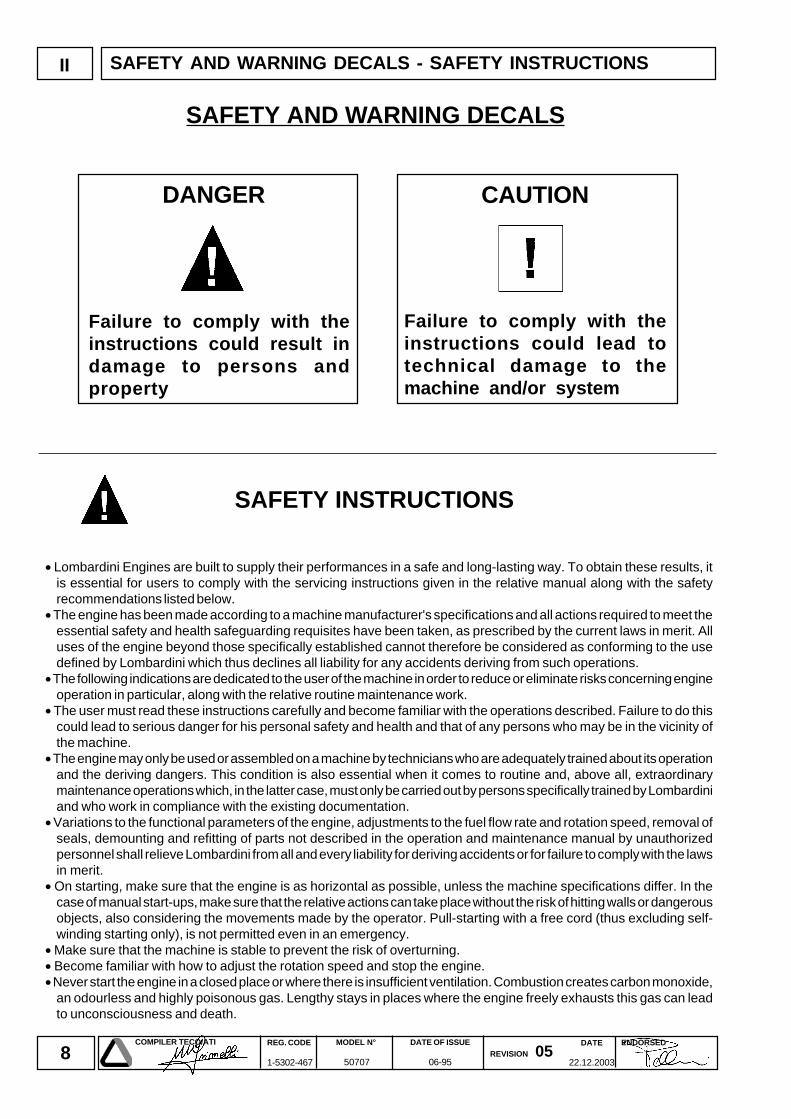
Failure to comply with theinstructions could result indamage to persons andproperty
Failure to comply with theinstructions could lead totechnical damage to themachine and/or system
DANGER
SAFETY AND WARNING DECALS
CAUTION
SAFETY INSTRUCTIONS
• Lombardini Engines are built to supply their performances in a safe and long-lasting way. To obtain these results, itis essential for users to comply with the servicing instructions given in the relative manual along with the safetyrecommendations listed below.
• The engine has been made according to a machine manufacturer's specifications and all actions required to meet theessential safety and health safeguarding requisites have been taken, as prescribed by the current laws in merit. Alluses of the engine beyond those specifically established cannot therefore be considered as conforming to the usedefined by Lombardini which thus declines all liability for any accidents deriving from such operations.
• The following indications are dedicated to the user of the machine in order to reduce or eliminate risks concerning engineoperation in particular, along with the relative routine maintenance work.
• The user must read these instructions carefully and become familiar with the operations described. Failure to do thiscould lead to serious danger for his personal safety and health and that of any persons who may be in the vicinity ofthe machine.
• The engine may only be used or assembled on a machine by technicians who are adequately trained about its operationand the deriving dangers. This condition is also essential when it comes to routine and, above all, extraordinarymaintenance operations which, in the latter case, must only be carried out by persons specifically trained by Lombardiniand who work in compliance with the existing documentation.
• Variations to the functional parameters of the engine, adjustments to the fuel flow rate and rotation speed, removal ofseals, demounting and refitting of parts not described in the operation and maintenance manual by unauthorizedpersonnel shall relieve Lombardini from all and every liability for deriving accidents or for failure to comply with the lawsin merit.
• On starting, make sure that the engine is as horizontal as possible, unless the machine specifications differ. In thecase of manual start-ups, make sure that the relative actions can take place without the risk of hitting walls or dangerousobjects, also considering the movements made by the operator. Pull-starting with a free cord (thus excluding self-winding starting only), is not permitted even in an emergency.
• Make sure that the machine is stable to prevent the risk of overturning.• Become familiar with how to adjust the rotation speed and stop the engine.• Never start the engine in a closed place or where there is insufficient ventilation. Combustion creates carbon monoxide,
an odourless and highly poisonous gas. Lengthy stays in places where the engine freely exhausts this gas can leadto unconsciousness and death.
SAFETY AND WARNING DECALS - SAFETY INSTRUCTIONS
9DATE
22.12.2003
COMPILER TECO/ATI REG. CODE
1-5302-467
MODEL N°
50707
DATE OF ISSUE
06-95REVISION 05
ENDORSED
II
• The engine must not operate in places containing inflammable materials, in explosive atmospheres, where there is dustthat can easily catch fire unles specific, adequate and clearly indicated precautions have been taken and have beencertified for the machine.
• To prevent fire hazards, always keep the machine at least one meter from buildings or from other machinery.• Children and animals must be kept at a due distance from operating machines in order to prevent hazards deriving
from their operation.• Fuel is inflammable. The tank must only be filled when the engine is off. Thoroughly dry any spilt fuel and move the
fuel container away along with any rags soaked in fuel or oil. Make sure that no soundproofing panels made ofporous material are soaked in fuel or oil. Make sure that the ground or floor on which the machine is standing hasnot soaked up any fuel or oil.
• Fully tighten the tank plug each time after refuelling. Do not fill the tank right to the top but leave an adequate spacefor the fuel to expand.
• Fuel vapour is highly toxic. Only refuel outdoors or in a well ventilated place.• Do not smoke or use naked flames when refuelling.• The engine must be started in compliance with the specific instructions in the operation manual of the engine and/or
machine itself. Do not use auxiliary starting aids that were not installed on the original machine (e.g. Startpilot’).• Before starting, remove any tools that were used to service the engine and/or machine. Make sure that all guards
have been refitted.• During operation, the surface of the engine can become dangerously hot. Avoid touching the exhaust system in
particular.• Before proceeding with any operation on the engine, stop it and allow it to cool. Never carry out any operation whilst
the engine is running.• The coolant fluid circuit is under pressure. Never carry out any inspections until the engine has cooled and even in
this case, only open the radiator plug or expansion chamber with the utmost caution, wearing protective garmentsand goggles. If there is an electric fan, do not approach the engine whilst it is still hot as the fan could also startoperating when the engine is at a standstill. Only clean the coolant system when the engine is at a standstill.
• When cleaning the oil-cooled air filter, make sure that the old oil is disposed of in the correct way in order tosafeguard the environment. The spongy filtering material in oil-cooled air filters must not be soaked in oil. Thereservoir of the separator pre-filter must not be filled with oil.
• The oil must be drained whilst the engine is hot (oil T ~ 80°C). Particular care is required to prevent burns. Do notallow the oil to come into contact with the skin.
• Make sure that the drained oil, the oil filter and the oil it contains are disposed of in the correct way in order tosafeguard the environment.
• Pay attention to the temperature of the oil filter when the filter itself is replaced.• Only check, top up and change the coolant fluid when the engine is off and cold. Take care to prevent fluids
containing nitrites from being mixed with others that do not contain these substances since "Nitrosamine",dangerous for the health, can form. The coolant fluid is polluting and must therefore be disposed of in the correctway to safeguard the environment.
• During operations that involve access to moving parts of the engine and/or removal of rotating guards, disconnectand insulate the positive wire of the battery to prevent accidental short-circuits and to stop the starter motor frombeing energized.
• Only check belt tension when the engine is off.• Only use the eyebolts installed by Lombardini to move the engine. These lifting points are not suitable for the entire
machine; in this case, the eyebolts installed by the manufacturer should be used.
SAFETY AND WARNING DECALS - SAFETY INSTRUCTIONS

10DATE
22.12.2003
COMPILER TECO/ATI REG. CODE
1-5302-467
MODEL N°
50707
DATE OF ISSUE
06-95REVISION 05
ENDORSED
NOTE
11DATE
22.12.2003
COMPILER TECO/ATI REG. CODE
1-5302-467
MODEL N°
50707
DATE OF ISSUE
06-95REVISION 05
ENDORSED
III
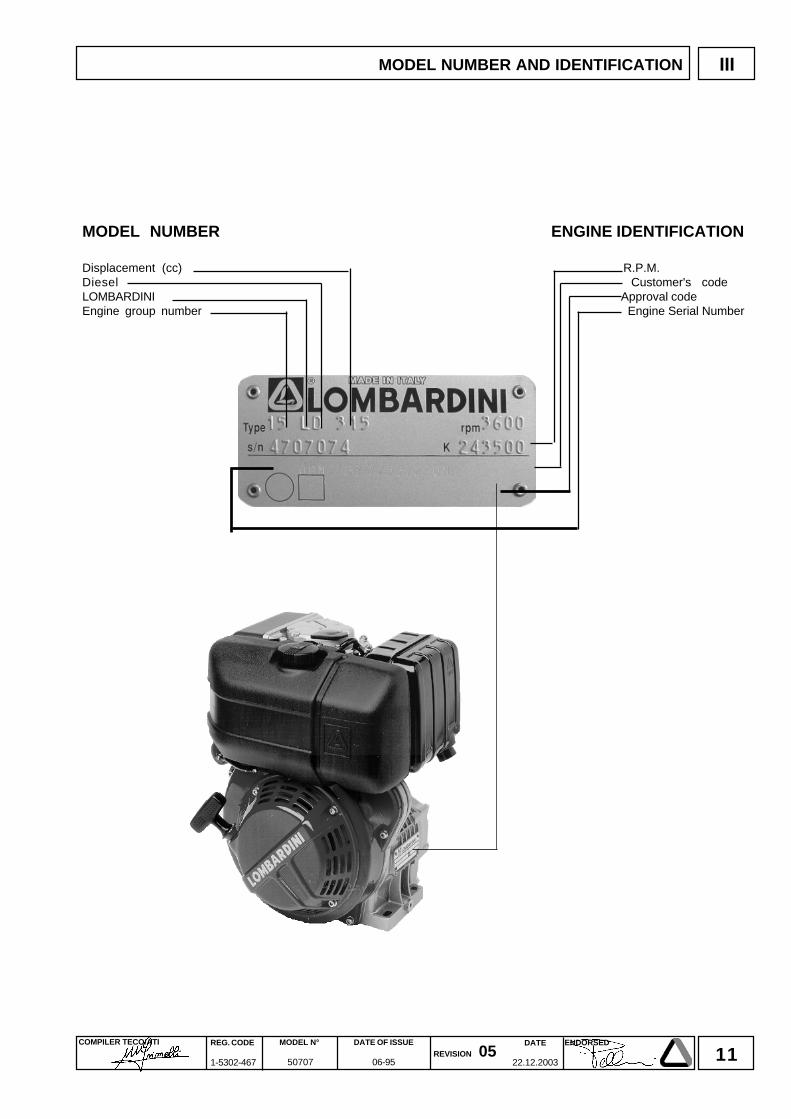
MODEL NUMBER ENGINE IDENTIFICATION
Displacement (cc) R.P.M.Diesel Customer's codeLOMBARDINI Approval codeEngine group number Engine Serial Number
MODEL NUMBER AND IDENTIFICATION
12DATE
22.12.2003
COMPILER TECO/ATI REG. CODE
1-5302-467
MODEL N°
50707
DATE OF ISSUE
06-95REVISION 05
ENDORSED
IV
15 LD 315
15 LD 350
15 LD 225
15LD 315
17866315
20,3:13600
5,0(6,8)4,6(6,2)4,1(5,6)
15@2400262
0,00351,2
12/4433480500020025°35°***
15LD 350
18266349
20,3:13600
5,5(7,5)5,1(7,0)4,7(6,4)
16,6@2400260
0,00381,2
12/4433540500020025°35°***
N.mmmmCm3
Nmg/kW.h
l/hlt
V/Ahkg
l./minl./min
kg.
15LD 225
1696022421:13600
3,5(4,8)3,3(4,5)3,1(4,2)
10,4@2400267
0,00210,9
12/3628350380015025°35°***
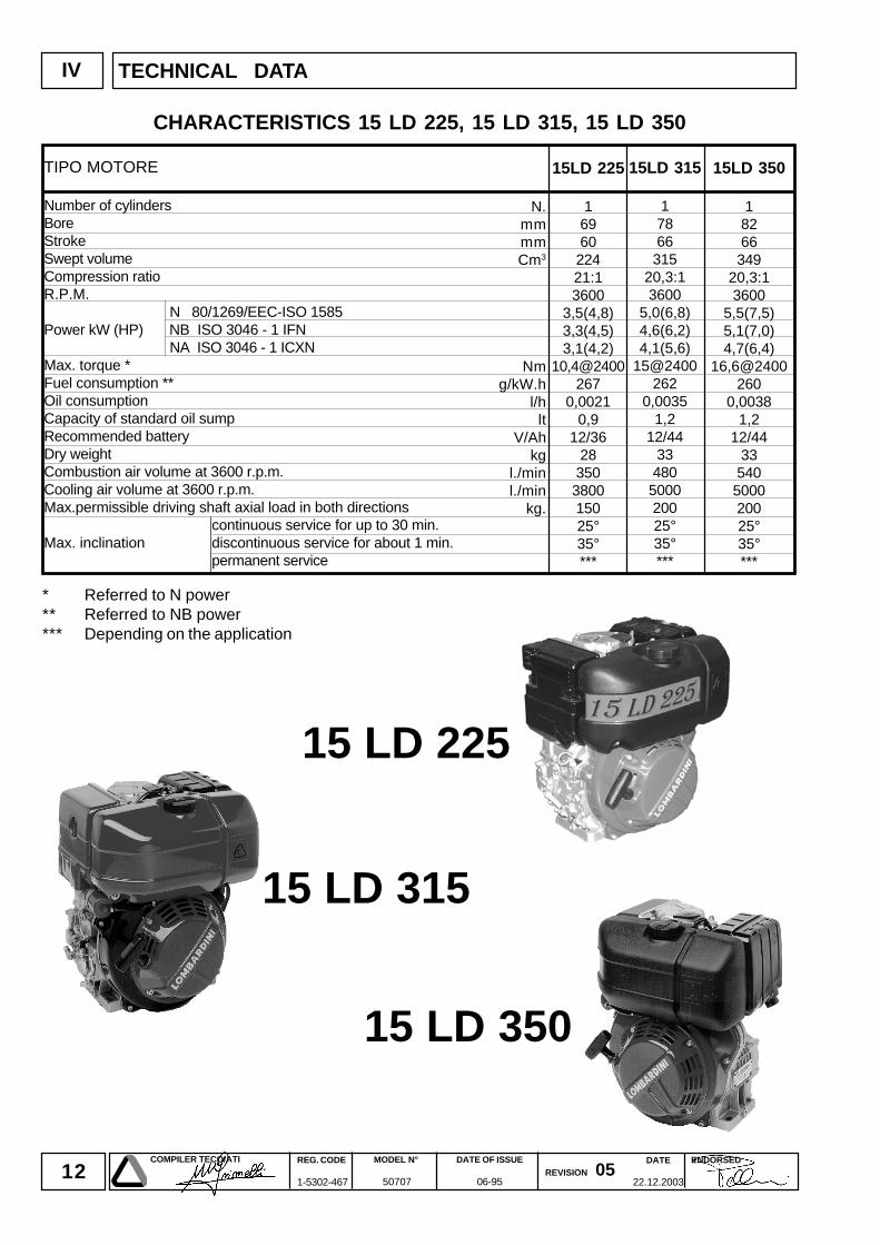
TIPO MOTORE
Number of cylindersBoreStrokeSwept volumeCompression ratioR.P.M.
N 80/1269/EEC-ISO 1585Power kW (HP) NB ISO 3046 - 1 IFN
NA ISO 3046 - 1 ICXNMax. torque *Fuel consumption **Oil consumptionCapacity of standard oil sumpRecommended batteryDry weightCombustion air volume at 3600 r.p.m.Cooling air volume at 3600 r.p.m.Max.permissible driving shaft axial load in both directions
continuous service for up to 30 min.Max. inclination discontinuous service for about 1 min.
permanent service
* Referred to N power** Referred to NB power*** Depending on the application
CHARACTERISTICS 15 LD 225, 15 LD 315, 15 LD 350
TECHNICAL DATA
13DATE
22.12.2003
COMPILER TECO/ATI REG. CODE
1-5302-467
MODEL N°
50707
DATE OF ISSUE
06-95REVISION 05
ENDORSED
IV
15LD 400
18276401
20,3:13600
7,0(9,5)6,4(8,7)5,8(7,9)
21,3@2400262
0,0051,5
12/4445580550020025°35°***
15LD 440
18676442
20,3:13600
7,7(10,5)7,0(9,6)6,4(8,7)
23,5@2400260
0,00551,5
12/4445635550020025°35°***
N.mmmmCm3
Nmg/kW.h
l/hlt
V/Ahkg
l./minl./min
kg.
15 LD 400
15 LD 440
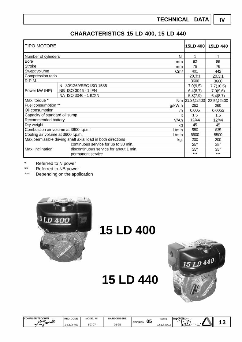
TIPO MOTORE
Number of cylindersBoreStrokeSwept volumeCompression ratioR.P.M.
N 80/1269/EEC-ISO 1585Power kW (HP) NB ISO 3046 - 1 IFN
NA ISO 3046 - 1 ICXNMax. torque *Fuel consumption **Oil consumptionCapacity of standard oil sumpRecommended batteryDry weightCombustion air volume at 3600 r.p.m.Cooling air volume at 3600 r.p.m.Max.permissible driving shaft axial load in both directions
continuous service for up to 30 min.Max. inclination discontinuous service for about 1 min.
permanent service
* Referred to N power** Referred to NB power*** Depending on the application
CHARACTERISTICS 15 LD 400, 15 LD 440
TECHNICAL DATA
14DATE
22.12.2003
COMPILER TECO/ATI REG. CODE
1-5302-467
MODEL N°
50707
DATE OF ISSUE
06-95REVISION 05
ENDORSED
V CHARACTERISTICS
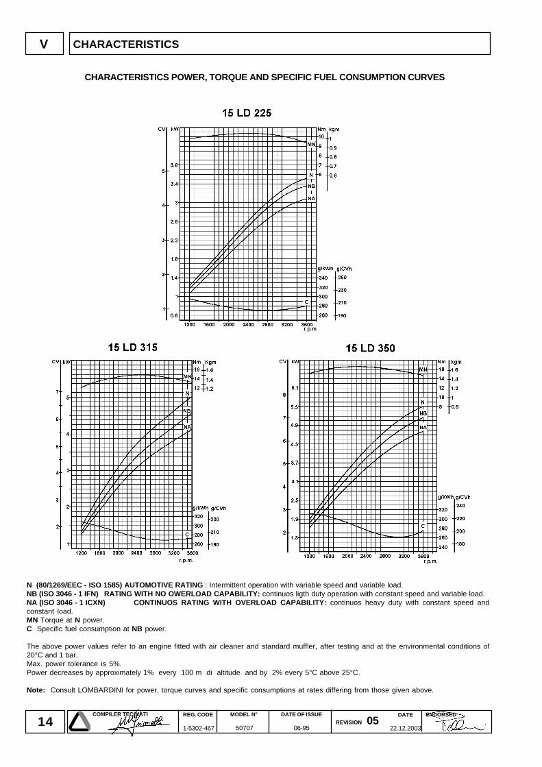
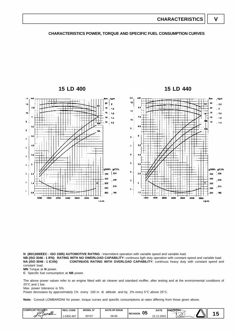
N (80/1269/EEC - ISO 1585) AUTOMOTIVE RATING : Intermittent operation with variable speed and variable load.NB (ISO 3046 - 1 IFN) RATING WITH NO OWERLOAD CAPABILITY: continuos ligth duty operation with constant speed and variable load.NA (ISO 3046 - 1 ICXN) CONTINUOS RATING WITH OVERLOAD CAPABILITY: continuos heavy duty with constant speed andconstant load.MN Torque at N power.C Specific fuel consumption at NB power.
The above power values refer to an engine fitted with air cleaner and standard muffler, after testing and at the environmental conditions of20°C and 1 bar.Max. power tolerance is 5%.Power decreases by approximately 1% every 100 m di altitude and by 2% every 5°C above 25°C.
Note: Consult LOMBARDINI for power, torque curves and specific consumptions at rates differing from those given above.
CHARACTERISTICS POWER, TORQUE AND SPECIFIC FUEL CONSUMPTION CURVES
15DATE
22.12.2003
COMPILER TECO/ATI REG. CODE
1-5302-467
MODEL N°
50707
DATE OF ISSUE
06-95REVISION 05
ENDORSED
V
15 LD 400 15 LD 440
CHARACTERISTICS
N (80/1269/EEC - ISO 1585) AUTOMOTIVE RATING : Intermittent operation with variable speed and variable load.NB (ISO 3046 - 1 IFN) RATING WITH NO OWERLOAD CAPABILITY: continuos ligth duty operation with constant speed and variable load.NA (ISO 3046 - 1 ICXN) CONTINUOS RATING WITH OVERLOAD CAPABILITY: continuos heavy duty with constant speed andconstant load.MN Torque at N power.C Specific fuel consumption at NB power.
The above power values refer to an engine fitted with air cleaner and standard muffler, after testing and at the environmental conditions of20°C and 1 bar.Max. power tolerance is 5%.Power decreases by approximately 1% every 100 m di altitude and by 2% every 5°C above 25°C.
Note: Consult LOMBARDINI for power, torque curves and specific consumptions at rates differing from those given above.
CHARACTERISTICS POWER, TORQUE AND SPECIFIC FUEL CONSUMPTION CURVES
16DATE
22.12.2003
COMPILER TECO/ATI REG. CODE
1-5302-467
MODEL N°
50707
DATE OF ISSUE
06-95REVISION 05
ENDORSED
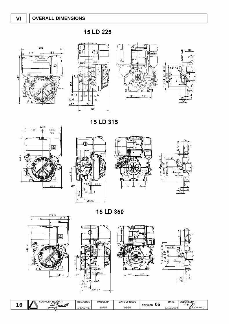
VI OVERALL DIMENSIONS
17DATE
22.12.2003
COMPILER TECO/ATI REG. CODE
1-5302-467
MODEL N°
50707
DATE OF ISSUE
06-95REVISION 05
ENDORSED
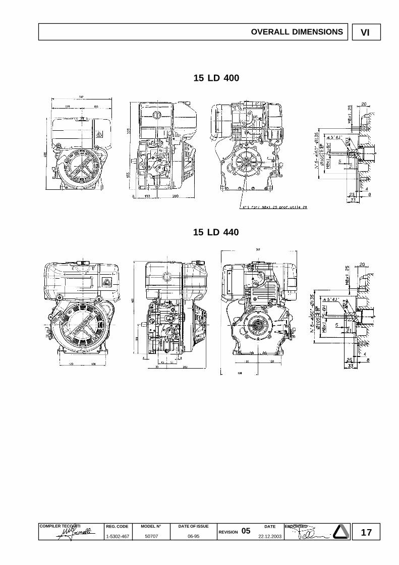
VI
15 LD 400
15 LD 440
OVERALL DIMENSIONS
18DATE
22.12.2003
COMPILER TECO/ATI REG. CODE
1-5302-467
MODEL N°
50707
DATE OF ISSUE
06-95REVISION 05
ENDORSED
VII
10 50 250 500
(*)(*)
(**)
(**) (***)
(°)
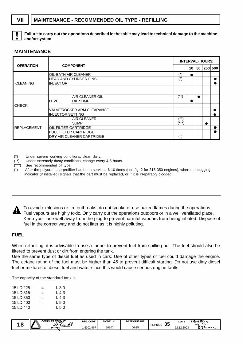
MAINTENANCE
INTERVAL (HOURS) OPERATION COMPONENT
OIL-BATH AIR CLEANERHEAD AND CYLINDER FINS
CLEANING INJECTOR
AIR CLEANER OILLEVEL OIL SUMP
CHECKVALVE/ROCKER ARM CLEARANCEINJECTOR SETTING
AIR CLEANERSUMP
REPLACEMENT OIL FILTER CARTRIDGEFUEL FILTER CARTRIDGEDRY AIR CLEANER CARTRIDGE
MAINTENANCE - RECOMMENDED OIL TYPE - REFILLING
To avoid explosions or fire outbreaks, do not smoke or use naked flames during the operations.Fuel vapours are highly toxic. Only carry out the operations outdoors or in a well ventilated place.Keep your face well away from the plug to prevent harmful vapours from being inhaled. Dispose offuel in the correct way and do not litter as it is highly polluting.
FUEL
When refuelling, it is advisable to use a funnel to prevent fuel from spilling out. The fuel should also befiltered to prevent dust or dirt from entering the tank.Use the same type of diesel fuel as used in cars. Use of other types of fuel could damage the engine.The cetane rating of the fuel must be higher than 45 to prevent difficult starting. Do not use dirty dieselfuel or mixtures of diesel fuel and water since this would cause serious engine faults.
The capacity of the standard tank is:
15 LD 225 = l. 3.015 LD 315 = l. 4.315 LD 350 = l. 4.315 LD 400 = l. 5.015 LD 440 = l. 5.0
Failure to carry out the operations described in the table may lead to technical damage to the machineand/or system
(*) Under severe working conditions, clean daily.(**) Under extremely dusty conditions, change every 4-5 hours.(***) See recommended oil type.(°) After the polyurethane prefilter has been serviced 6-10 times (see fig. 2 for 315-350 engines), when the clogging
indicator (if installed) signals that the part must be replaced, or if it is irreparably clogged.
19DATE
22.12.2003
COMPILER TECO/ATI REG. CODE
1-5302-467
MODEL N°
50707
DATE OF ISSUE
06-95REVISION 05
ENDORSED
VII
-30
-25
-20
-15
-10
-5 0
+5
+10
+15
+20
+25
+30
+35
+40
+45
SAE 20W
SAE 10W
+50
SAE 30
SAE 40
SAE 10W-30
SAE 10W-40
SAE 10W-60
SAE 15W-40 base minerale
SAE 15W-40 base semi-sintetica
SAE 20W-60 base semi-sintetica
SAE 5W-30 base sintetica
SAE 0W-30 base sintetica
SAE 5W-40 base sintetica
-35
-40
CCMC G- 2
CF CE CD CC CB CA SA SB SC SD SE SF SG
DIESELBENZINA - ESSENCE - PETROL
BENZIN - GASOLINA
CCMC G- 3 G- 5CCMC PD - 1 / PD - 2
CCMC D- 2D- 4CCMC D- 3D- 5
MIL - L - 2104 DMIL - L - 2104 E
MIL - L -46152 CMIL - L- 46152 D/E
MB 226.1 MB 226.5MB 227.1 MB 227.5
228.3 MB 228.1
VW 501.01VW 500.00
SHAPIG- 4
SJ
VOLVO VDS
MAN QC 13-017
VW 505.00
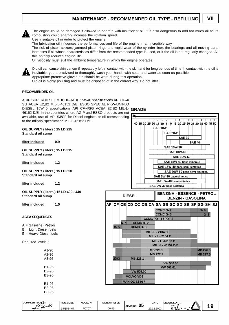
RECOMMENDED OIL
AGIP SUPERDIESEL MULTIGRADE 15W40 specifications API CF-4/SG ACEA E2,B2 MIL-L-46152 D/E. ESSO SPECIAL PKW-UNIFLODIESEL 15W40 specifications API CF-4/SG ACEA E2,B2 MIL-L-46152 D/E. In the countries where AGIP and ESSO products are notavailable, use oil API SJ/CF for Diesel engines or oil correspondingto the military specification MIL-L-46152 D/E.
OIL SUPPLY ( liters ) 15 LD 225Standard oil sump
filter included 0.9
OIL SUPPLY ( liters ) 15 LD 315Standard oil sump
filter included 1.2
OIL SUPPLY ( liters ) 15 LD 350Standard oil sump
filter included 1.2
OIL SUPPLY ( liters ) 15 LD 400 - 440Standard oil sump
filter included 1.5
ACEA SEQUENCES
A = Gasoline (Petrol)B = Light Diesel fuelsE = Heavy Diesel fuels
Required levels :
A1-96A2-96A3-96
B1-96B2-96B3-96
E1-96E2-96E3-96
The engine could be damaged if allowed to operate with insufficient oil. It is also dangerous to add too much oil as itscombustion could sharply increase the rotation speed.Use a suitable oil in order to protect the engine.The lubrication oil influences the performances and life of the engine in an incredible way.The risk of piston seizure, jammed piston rings and rapid wear of the cylinder liner, the bearings and all moving partsincreases if oil whose characteristics differ from the recommended type is used, or if the oil is not regularly changed. Allthis notably reduces engine life.Oil viscosity must suit the ambient temperature in which the engine operates.
Old oil can cause skin cancer if repeatedly left in contact with the skin and for long periods of time. If contact with the oil isinevitable, you are advised to thoroughly wash your hands with soap and water as soon as possible.Appropriate protective gloves etc should be wore during this operation.Old oil is highly polluting and must be disposed of in the correct way. Do not litter.
MAINTENANCE - RECOMMENDED OIL TYPE - REFILLING
GRADE
20DATE
22.12.2003
COMPILER TECO/ATI REG. CODE
1-5302-467
MODEL N°
50707
DATE OF ISSUE
06-95REVISION 05
ENDORSED
1 2
3
VIII DISASSEMBLY/REASSEMBLY
WARNINGS!During repair operations, whenusing compressed air, wear eyeprotection.
DISASSEMBLY AND REASSEMBLY
Besides disassembly and reassembly operations this chapter alsoincludes checking and setting specifications, dimensions, repairand operating instructions. Always use original LOMBARDINI spareparts for repair operations.
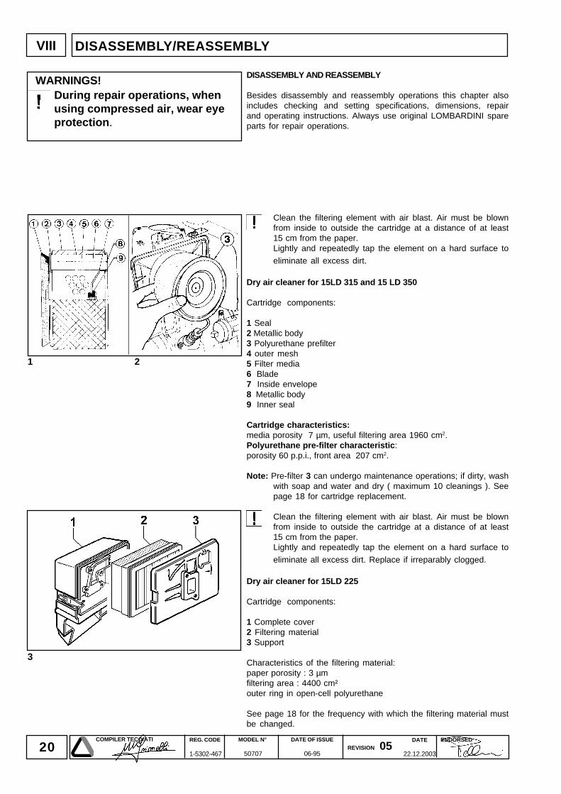
Clean the filtering element with air blast. Air must be blownfrom inside to outside the cartridge at a distance of at least15 cm from the paper.Lightly and repeatedly tap the element on a hard surface to
eliminate all excess dirt.
Dry air cleaner for 15LD 315 and 15 LD 350
Cartridge components:
1 Seal2 Metallic body3 Polyurethane prefilter4 outer mesh5 Filter media6 Blade7 Inside envelope8 Metallic body9 Inner seal
Cartridge characteristics:media porosity 7 µm, useful filtering area 1960 cm2.Polyurethane pre-filter characteristic:porosity 60 p.p.i., front area 207 cm2.
Note: Pre-filter 3 can undergo maintenance operations; if dirty, washwith soap and water and dry ( maximum 10 cleanings ). Seepage 18 for cartridge replacement.
Clean the filtering element with air blast. Air must be blownfrom inside to outside the cartridge at a distance of at least15 cm from the paper.Lightly and repeatedly tap the element on a hard surface to
eliminate all excess dirt. Replace if irreparably clogged.
Dry air cleaner for 15LD 225
Cartridge components:
1 Complete cover2 Filtering material3 Support
Characteristics of the filtering material:paper porosity : 3 µmfiltering area : 4400 cm²outer ring in open-cell polyurethane
See page 18 for the frequency with which the filtering material mustbe changed.
21DATE
22.12.2003
COMPILER TECO/ATI REG. CODE
1-5302-467
MODEL N°
50707
DATE OF ISSUE
06-95REVISION 05
ENDORSED
VIII
5 5a
4 4a
6
7
DISASSEMBLY/REASSEMBLY
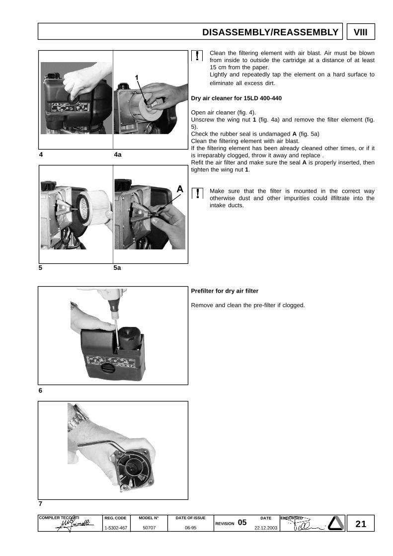
Clean the filtering element with air blast. Air must be blownfrom inside to outside the cartridge at a distance of at least15 cm from the paper.Lightly and repeatedly tap the element on a hard surface to
eliminate all excess dirt.
Dry air cleaner for 15LD 400-440
Open air cleaner (fig. 4).Unscrew the wing nut 1 (fig. 4a) and remove the filter element (fig.5).Check the rubber seal is undamaged A (fig. 5a)Clean the filtering element with air blast.If the filtering element has been already cleaned other times, or if itis irreparably clogged, throw it away and replace .Refit the air filter and make sure the seal A is properly inserted, thentighten the wing nut 1.
Make sure that the filter is mounted in the correct wayotherwise dust and other impurities could ilfiltrate into theintake ducts.
Prefilter for dry air filter
Remove and clean the pre-filter if clogged.
22DATE
22.12.2003
COMPILER TECO/ATI REG. CODE
1-5302-467
MODEL N°
50707
DATE OF ISSUE
06-95REVISION 05
ENDORSED
8
VIII
11
9 10
A
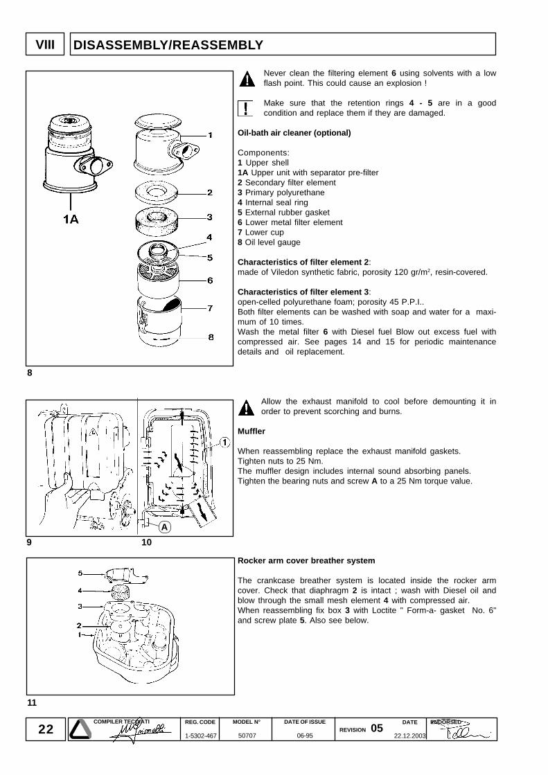
Never clean the filtering element 6 using solvents with a lowflash point. This could cause an explosion !
Make sure that the retention rings 4 - 5 are in a goodcondition and replace them if they are damaged.
Oil-bath air cleaner (optional)
Components:1 Upper shell1A Upper unit with separator pre-filter2 Secondary filter element3 Primary polyurethane4 Internal seal ring5 External rubber gasket6 Lower metal filter element7 Lower cup8 Oil level gauge
Characteristics of filter element 2:made of Viledon synthetic fabric, porosity 120 gr/m2, resin-covered.
Characteristics of filter element 3:open-celled polyurethane foam; porosity 45 P.P.I..Both filter elements can be washed with soap and water for a maxi-mum of 10 times.Wash the metal filter 6 with Diesel fuel Blow out excess fuel withcompressed air. See pages 14 and 15 for periodic maintenancedetails and oil replacement.
Allow the exhaust manifold to cool before demounting it inorder to prevent scorching and burns.
Muffler
When reassembling replace the exhaust manifold gaskets.Tighten nuts to 25 Nm.The muffler design includes internal sound absorbing panels.Tighten the bearing nuts and screw A to a 25 Nm torque value.
Rocker arm cover breather system
The crankcase breather system is located inside the rocker armcover. Check that diaphragm 2 is intact ; wash with Diesel oil andblow through the small mesh element 4 with compressed air.When reassembling fix box 3 with Loctite " Form-a- gasket No. 6"and screw plate 5. Also see below.
DISASSEMBLY/REASSEMBLY
23DATE
22.12.2003
COMPILER TECO/ATI REG. CODE
1-5302-467
MODEL N°
50707
DATE OF ISSUE
06-95REVISION 05
ENDORSED
12
13
VIII
13a
13b
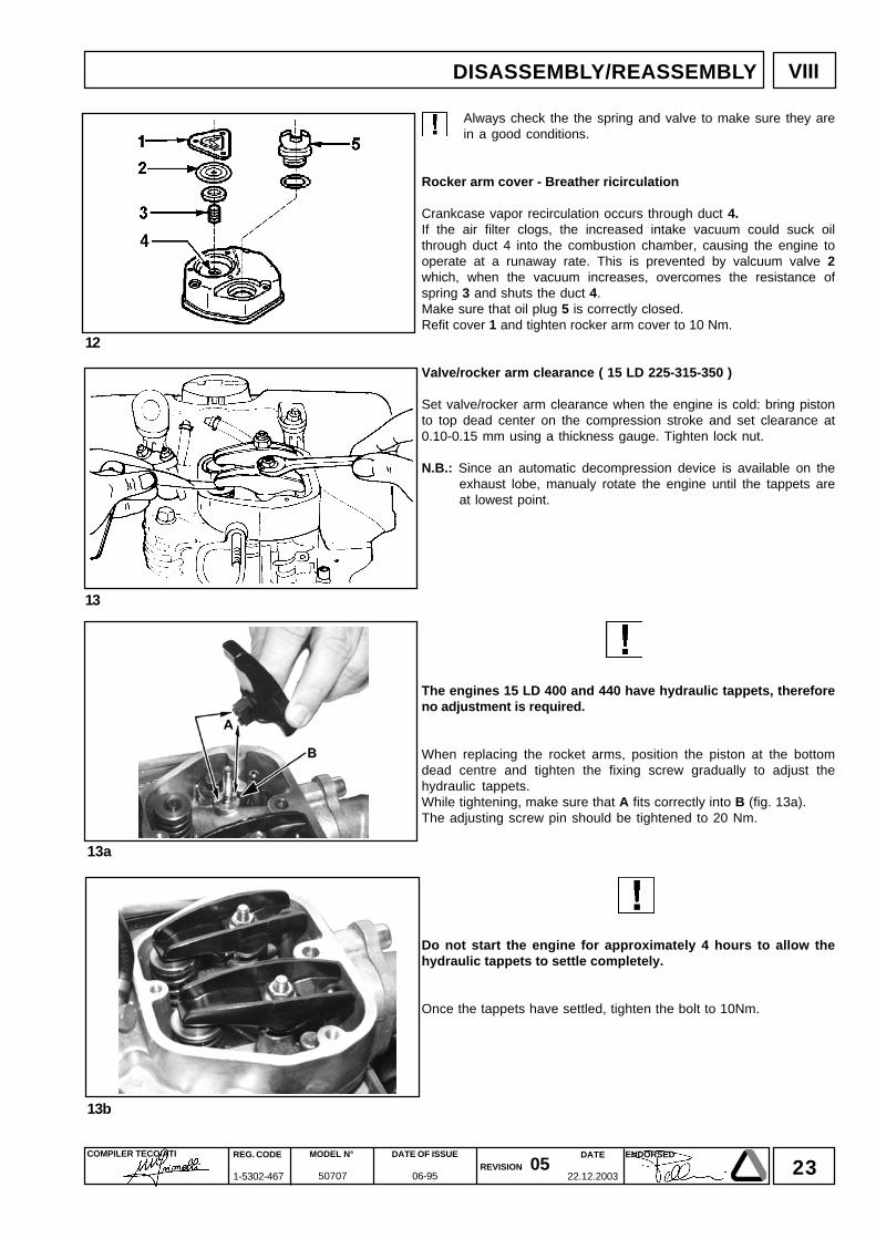
Always check the the spring and valve to make sure they arein a good conditions.
Rocker arm cover - Breather ricirculation
Crankcase vapor recirculation occurs through duct 4.If the air filter clogs, the increased intake vacuum could suck oilthrough duct 4 into the combustion chamber, causing the engine tooperate at a runaway rate. This is prevented by valcuum valve 2which, when the vacuum increases, overcomes the resistance ofspring 3 and shuts the duct 4.Make sure that oil plug 5 is correctly closed.Refit cover 1 and tighten rocker arm cover to 10 Nm.
Valve/rocker arm clearance ( 15 LD 225-315-350 )
Set valve/rocker arm clearance when the engine is cold: bring pistonto top dead center on the compression stroke and set clearance at0.10-0.15 mm using a thickness gauge. Tighten lock nut.
N.B.: Since an automatic decompression device is available on theexhaust lobe, manualy rotate the engine until the tappets areat lowest point.
The engines 15 LD 400 and 440 have hydraulic tappets, thereforeno adjustment is required.
When replacing the rocket arms, position the piston at the bottomdead centre and tighten the fixing screw gradually to adjust thehydraulic tappets.While tightening, make sure that A fits correctly into B (fig. 13a).The adjusting screw pin should be tightened to 20 Nm.
Do not start the engine for approximately 4 hours to allow thehydraulic tappets to settle completely.
Once the tappets have settled, tighten the bolt to 10Nm.
DISASSEMBLY/REASSEMBLY
24DATE
22.12.2003
COMPILER TECO/ATI REG. CODE
1-5302-467
MODEL N°
50707
DATE OF ISSUE
06-95REVISION 05
ENDORSED
VIII DISASSEMBLY/REASSEMBLY
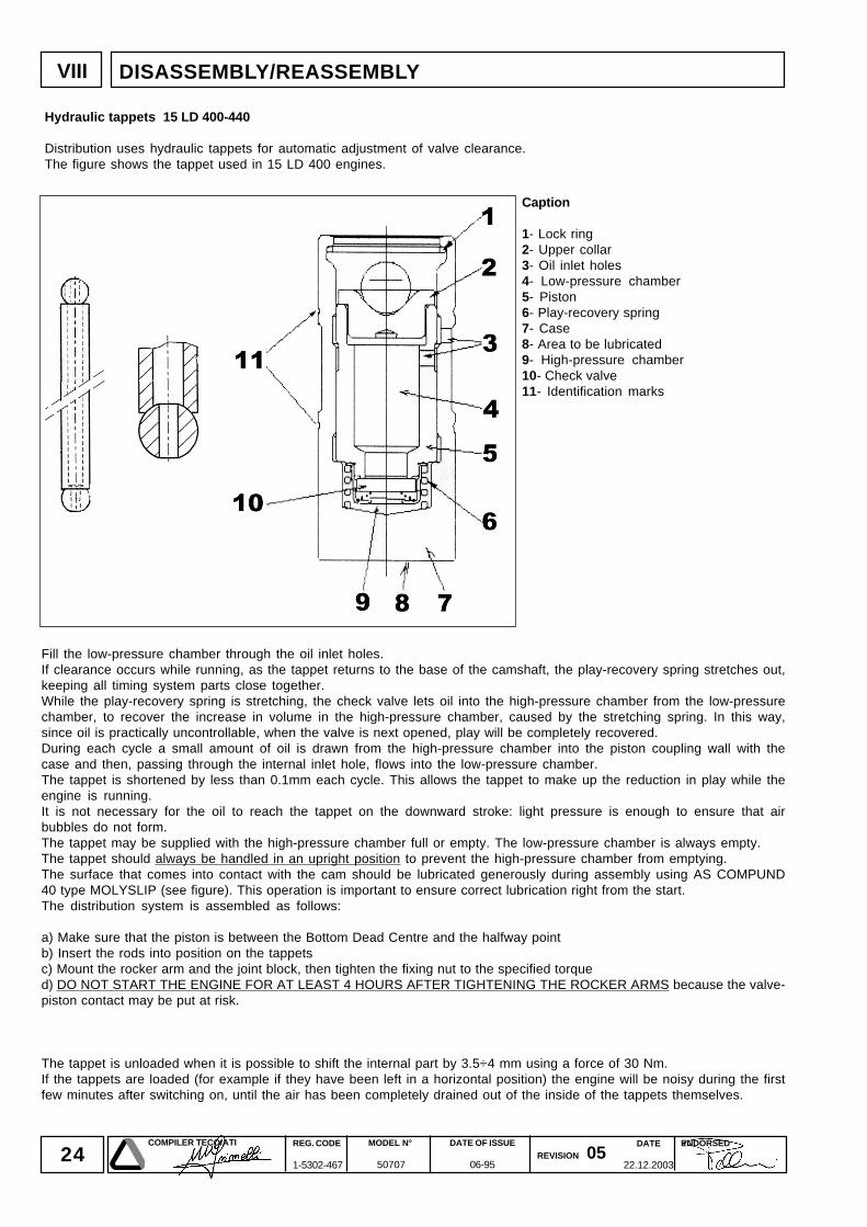
Fill the low-pressure chamber through the oil inlet holes.If clearance occurs while running, as the tappet returns to the base of the camshaft, the play-recovery spring stretches out,keeping all timing system parts close together.While the play-recovery spring is stretching, the check valve lets oil into the high-pressure chamber from the low-pressurechamber, to recover the increase in volume in the high-pressure chamber, caused by the stretching spring. In this way,since oil is practically uncontrollable, when the valve is next opened, play will be completely recovered.During each cycle a small amount of oil is drawn from the high-pressure chamber into the piston coupling wall with thecase and then, passing through the internal inlet hole, flows into the low-pressure chamber.The tappet is shortened by less than 0.1mm each cycle. This allows the tappet to make up the reduction in play while theengine is running.It is not necessary for the oil to reach the tappet on the downward stroke: light pressure is enough to ensure that airbubbles do not form.The tappet may be supplied with the high-pressure chamber full or empty. The low-pressure chamber is always empty.The tappet should always be handled in an upright position to prevent the high-pressure chamber from emptying.The surface that comes into contact with the cam should be lubricated generously during assembly using AS COMPUND40 type MOLYSLIP (see figure). This operation is important to ensure correct lubrication right from the start.The distribution system is assembled as follows:
a) Make sure that the piston is between the Bottom Dead Centre and the halfway pointb) Insert the rods into position on the tappetsc) Mount the rocker arm and the joint block, then tighten the fixing nut to the specified torqued) DO NOT START THE ENGINE FOR AT LEAST 4 HOURS AFTER TIGHTENING THE ROCKER ARMS because the valve-piston contact may be put at risk.
The tappet is unloaded when it is possible to shift the internal part by 3.5÷4 mm using a force of 30 Nm.If the tappets are loaded (for example if they have been left in a horizontal position) the engine will be noisy during the firstfew minutes after switching on, until the air has been completely drained out of the inside of the tappets themselves.
Caption
1- Lock ring2- Upper collar3- Oil inlet holes4- Low-pressure chamber5- Piston6- Play-recovery spring7- Case8- Area to be lubricated9- High-pressure chamber10- Check valve11- Identification marks
Hydraulic tappets 15 LD 400-440
Distribution uses hydraulic tappets for automatic adjustment of valve clearance.The figure shows the tappet used in 15 LD 400 engines.
25DATE
22.12.2003
COMPILER TECO/ATI REG. CODE
1-5302-467
MODEL N°
50707
DATE OF ISSUE
06-95REVISION 05
ENDORSED
VIII
14
15
16 17
DISASSEMBLY/REASSEMBLY
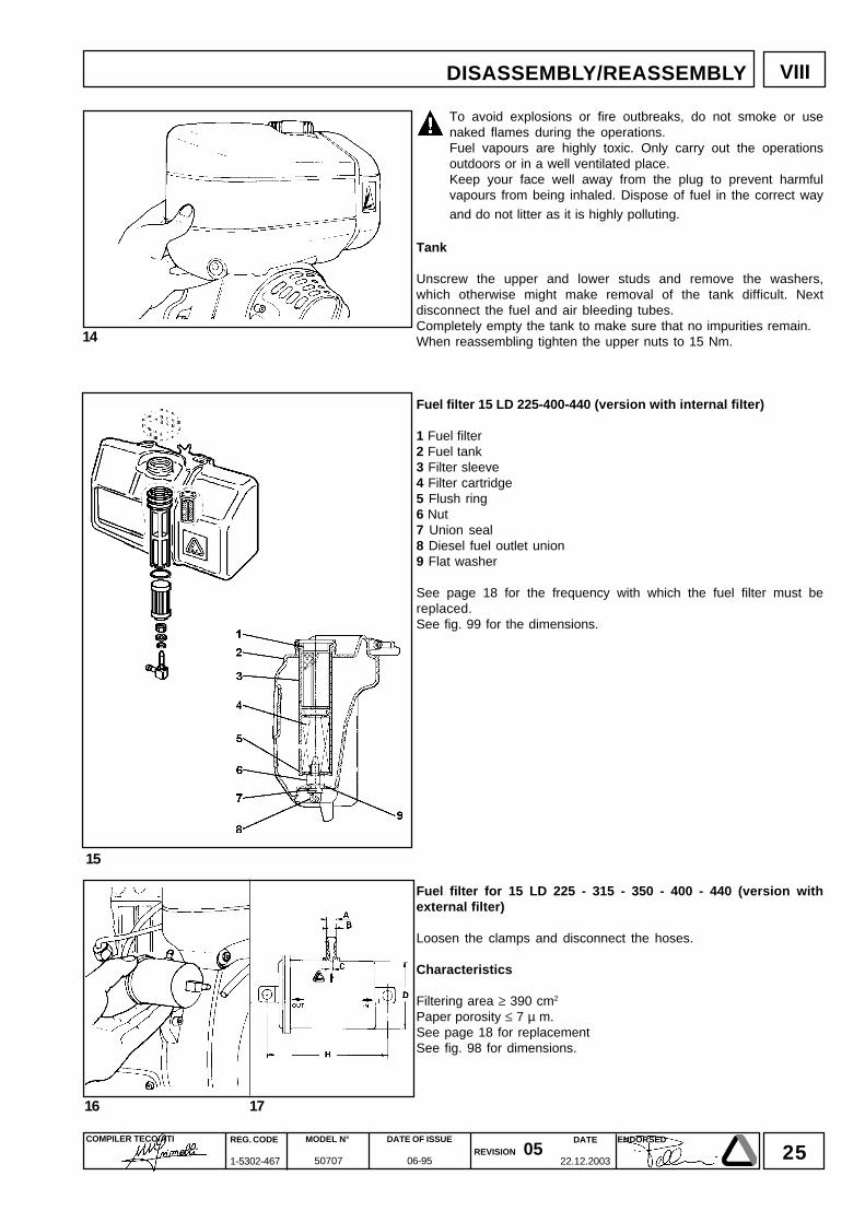
To avoid explosions or fire outbreaks, do not smoke or usenaked flames during the operations.Fuel vapours are highly toxic. Only carry out the operationsoutdoors or in a well ventilated place.Keep your face well away from the plug to prevent harmfulvapours from being inhaled. Dispose of fuel in the correct way
and do not litter as it is highly polluting.
Tank
Unscrew the upper and lower studs and remove the washers,which otherwise might make removal of the tank difficult. Nextdisconnect the fuel and air bleeding tubes.Completely empty the tank to make sure that no impurities remain.When reassembling tighten the upper nuts to 15 Nm.
Fuel filter 15 LD 225-400-440 (version with internal filter)
1 Fuel filter2 Fuel tank3 Filter sleeve4 Filter cartridge5 Flush ring6 Nut7 Union seal8 Diesel fuel outlet union9 Flat washer
See page 18 for the frequency with which the fuel filter must bereplaced.See fig. 99 for the dimensions.
Fuel filter for 15 LD 225 - 315 - 350 - 400 - 440 (version withexternal filter)
Loosen the clamps and disconnect the hoses.
Characteristics
Filtering area ≥ 390 cm2
Paper porosity ≤ 7 µ m.See page 18 for replacementSee fig. 98 for dimensions.
26DATE
22.12.2003
COMPILER TECO/ATI REG. CODE
1-5302-467
MODEL N°
50707
DATE OF ISSUE
06-95REVISION 05
ENDORSED
VIII
20
18
19
DISASSEMBLY/REASSEMBLY
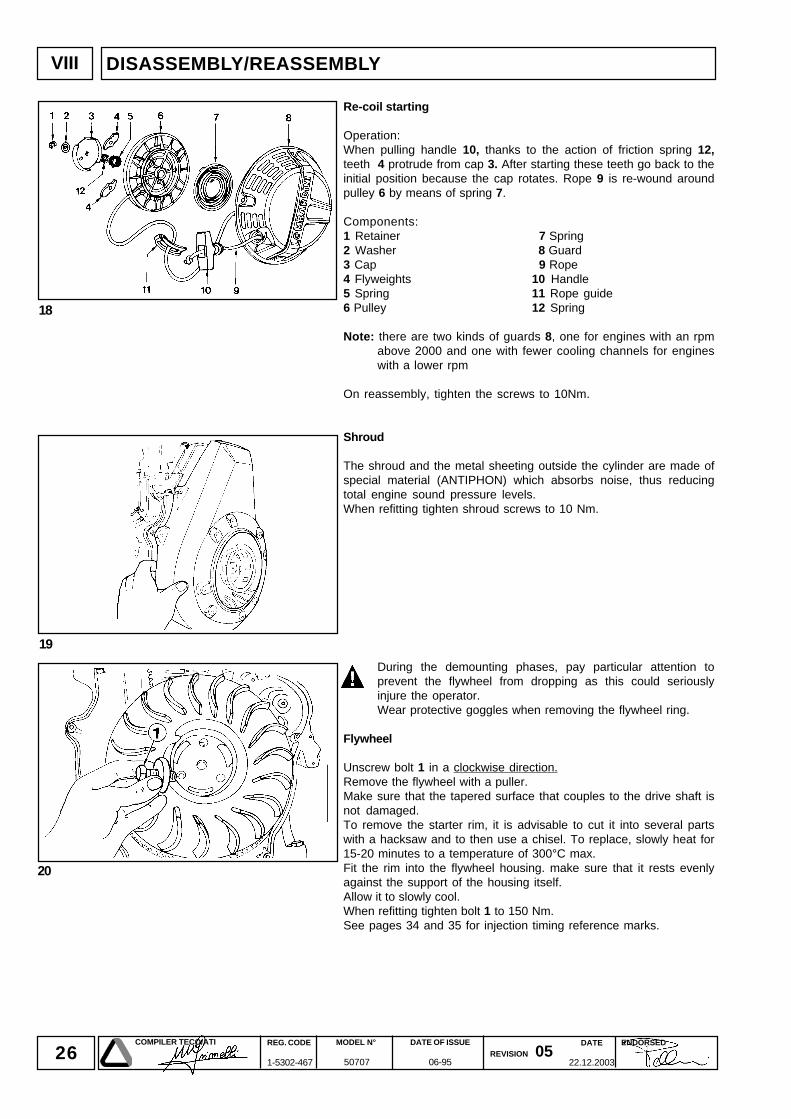
Re-coil starting
Operation:When pulling handle 10, thanks to the action of friction spring 12,teeth 4 protrude from cap 3. After starting these teeth go back to theinitial position because the cap rotates. Rope 9 is re-wound aroundpulley 6 by means of spring 7.
Components:1 Retainer 7 Spring2 Washer 8 Guard3 Cap 9 Rope4 Flyweights 10 Handle5 Spring 11 Rope guide6 Pulley 12 Spring
Note: there are two kinds of guards 8, one for engines with an rpmabove 2000 and one with fewer cooling channels for engineswith a lower rpm
On reassembly, tighten the screws to 10Nm.
Shroud
The shroud and the metal sheeting outside the cylinder are made ofspecial material (ANTIPHON) which absorbs noise, thus reducingtotal engine sound pressure levels.When refitting tighten shroud screws to 10 Nm.
During the demounting phases, pay particular attention toprevent the flywheel from dropping as this could seriouslyinjure the operator.Wear protective goggles when removing the flywheel ring.
Flywheel
Unscrew bolt 1 in a clockwise direction.Remove the flywheel with a puller.Make sure that the tapered surface that couples to the drive shaft isnot damaged.To remove the starter rim, it is advisable to cut it into several partswith a hacksaw and to then use a chisel. To replace, slowly heat for15-20 minutes to a temperature of 300°C max.Fit the rim into the flywheel housing. make sure that it rests evenlyagainst the support of the housing itself.Allow it to slowly cool.When refitting tighten bolt 1 to 150 Nm.See pages 34 and 35 for injection timing reference marks.
27DATE
22.12.2003
COMPILER TECO/ATI REG. CODE
1-5302-467
MODEL N°
50707
DATE OF ISSUE
06-95REVISION 05
ENDORSED
VIII
21
22
DISASSEMBLY/REASSEMBLY
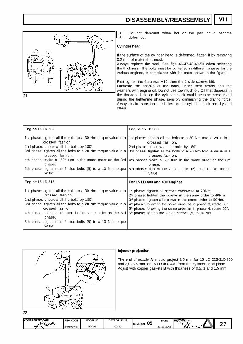
Do not demount when hot or the part could becomedeformed.
Cylinder head
If the surface of the cylinder head is deformed, flatten it by removing0.2 mm of material at most.Always replace the seal. See figs 46-47-48-49-50 when selectingthe thickness. The bolts must be tightened in different phases for thevarious engines, in compliance with the order shown in the figure:
First tighten the 4 screws M10, then the 2 side screws M6.Lubricate the shanks of the bolts, under their heads and thewashers with engine oil. Do not use too much oil. Oil that deposits inthe threaded hole on the cylinder block could become pressurizedduring the tightening phase, sensibly diminishing the driving force.Always make sure that the holes on the cylinder block are dry andclean.
Injector projection
The end of nozzle A should project 2,5 mm for 15 LD 225-315-350and 3,0÷3,5 mm for 15 LD 400-440 from the cylinder head plane.Adjust with copper gaskets B with thickness of 0.5, 1 and 1.5 mm
Engine 15 LD 350
1st phase: tighten all the bolts to a 30 Nm torque value in acrossed fashion.
2nd phase: unscrew all the bolts by 180°.3rd phase: tighten all the bolts to a 20 Nm torque value in a
crossed fashion.4th phase: make a 60° turn in the same order as the 3rd
phase.5th phase: tighten the 2 side bolts (5) to a 10 Nm torque
value
For 15 LD 400 and 400 engines
1st phase: tighten all screws crosswise to 20Nm.2nd phase: tighten the screws in the same order to 40Nm.3rd phase: tighten all screws in the same order to 50Nm.4th phase: following the same order as in phase 3, rotate 60°.5th phase: following the same order as in phase 4, rotate 60°.6th phase: tighten the 2 side screws (5) to 10 Nm
Engine 15 LD 225
1st phase: tighten all the bolts to a 30 Nm torque value in acrossed fashion.
2nd phase: unscrew all the bolts by 180°.3rd phase: tighten all the bolts to a 20 Nm torque value in a
crossed fashion.4th phase: make a 52° turn in the same order as the 3rd
phase.5th phase: tighten the 2 side bolts (5) to a 10 Nm torque
value.
Engine 15 LD 315
1st phase: tighten all the bolts to a 30 Nm torque value in acrossed fashion.
2nd phase: unscrew all the bolts by 180°.3rd phase: tighten all the bolts to a 20 Nm torque value in a
crossed fashion.4th phase: make a 72° turn in the same order as the 3rd
phase.5th phase: tighten the 2 side bolts (5) to a 10 Nm torque
value.
28DATE
22.12.2003
COMPILER TECO/ATI REG. CODE
1-5302-467
MODEL N°
50707
DATE OF ISSUE
06-95REVISION 05
ENDORSED
VIII
25 26
27
23 24
DISASSEMBLY/REASSEMBLY
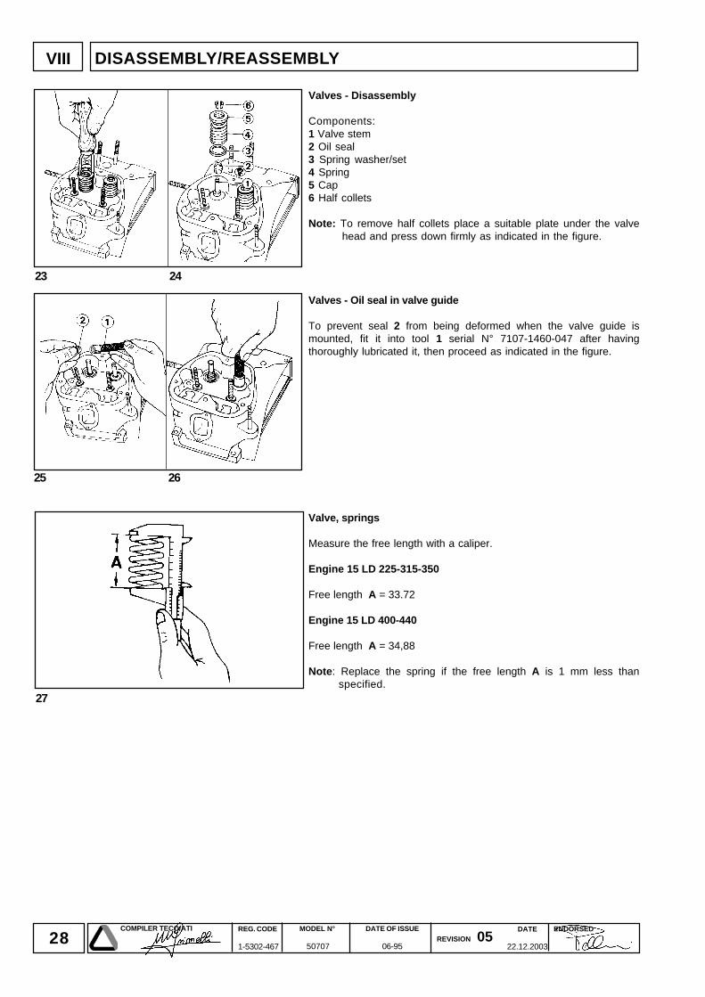
Valves - Disassembly
Components:1 Valve stem2 Oil seal3 Spring washer/set4 Spring5 Cap6 Half collets
Note: To remove half collets place a suitable plate under the valvehead and press down firmly as indicated in the figure.
Valves - Oil seal in valve guide
To prevent seal 2 from being deformed when the valve guide ismounted, fit it into tool 1 serial N° 7107-1460-047 after havingthoroughly lubricated it, then proceed as indicated in the figure.
Valve, springs
Measure the free length with a caliper.
Engine 15 LD 225-315-350
Free length A = 33.72
Engine 15 LD 400-440
Free length A = 34,88
Note: Replace the spring if the free length A is 1 mm less thanspecified.
29DATE
22.12.2003
COMPILER TECO/ATI REG. CODE
1-5302-467
MODEL N°
50707
DATE OF ISSUE
06-95REVISION 05
ENDORSED
VIII
30
29
28
DISASSEMBLY/REASSEMBLY
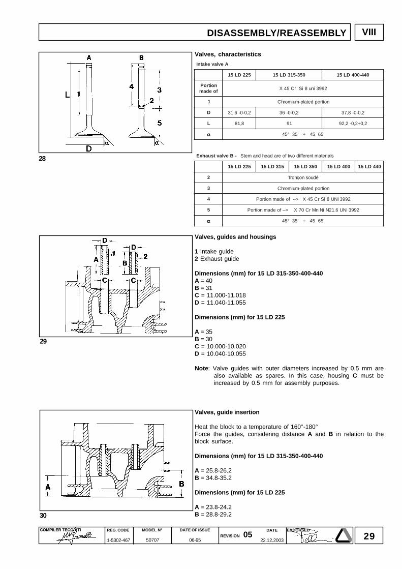
Valves, characteristics
Valves, guides and housings
1 Intake guide2 Exhaust guide
Dimensions (mm) for 15 LD 315-350-400-440A = 40B = 31C = 11.000-11.018D = 11.040-11.055
Dimensions (mm) for 15 LD 225
A = 35B = 30C = 10.000-10.020D = 10.040-10.055
Note: Valve guides with outer diameters increased by 0.5 mm arealso available as spares. In this case, housing C must beincreased by 0.5 mm for assembly purposes.
Valves, guide insertion
Heat the block to a temperature of 160°-180°Force the guides, considering distance A and B in relation to theblock surface.
Dimensions (mm) for 15 LD 315-350-400-440
A = 25.8-26.2B = 34.8-35.2
Dimensions (mm) for 15 LD 225
A = 23.8-24.2B = 28.8-29.2
AevlavekatnI
522DL51 053-513DL51 044-004DL51
noitroPfoedam 2993inu8iSrC54X
1 noitropdetalp-muimorhC
D 2,0-0-6,13 2,0-0-63 2,0-0-8,73
L 8,18 19 2,0+2,0-2,29
ααααα '5654÷'53°54
-BevlavtsuahxE slairetamtnereffidowtfoeradaehdnametS
522DL51 513DL51 053DL51 004DL51 044DL51
2 éduosnoçnorT
3 noitropdetalp-muimorhC
4 2993INU8iSrC54X>--foedamnoitroP
5 2993INU6.12NiNnMrC07X>--foedamnoitroP
ααααα '5654÷'53°54
30DATE
22.12.2003
COMPILER TECO/ATI REG. CODE
1-5302-467
MODEL N°
50707
DATE OF ISSUE
06-95REVISION 05
ENDORSED
31
32
33 34
VIII
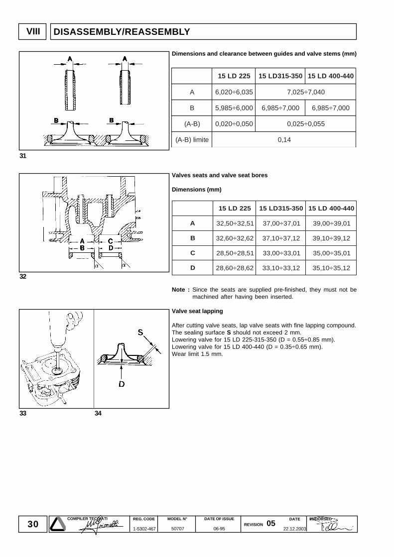
522DL51 053-513DL51 044-004DL51
A 530,6÷020,6 040,7÷520,7
B 000,6÷589,5 000,7÷589,6 000,7÷589,6
)B-A( 050,0÷020,0 550,0÷520,0
etimil)B-A( 41,0
522DL51 053-513DL51 044-004DL51
A 15,23÷05,23 10,73÷00,73 10,93÷00,93
B 26,23÷06,23 21,73÷01,73 21,93÷01,93
C 15,82÷05,82 10,33÷00,33 10,53÷00,53
D 26,82÷06,82 21,33÷01,33 21,53÷01,53
DISASSEMBLY/REASSEMBLY
Dimensions and clearance between guides and valve stems (mm)
Valves seats and valve seat bores
Dimensions (mm)
Note : Since the seats are supplied pre-finished, they must not bemachined after having been inserted.
Valve seat lapping
After cutting valve seats, lap valve seats with fine lapping compound.The sealing surface S should not exceed 2 mm.Lowering valve for 15 LD 225-315-350 (D = 0.55÷0.85 mm).Lowering valve for 15 LD 400-440 (D = 0.35÷0.65 mm).Wear limit 1.5 mm.
31DATE
22.12.2003
COMPILER TECO/ATI REG. CODE
1-5302-467
MODEL N°
50707
DATE OF ISSUE
06-95REVISION 05
ENDORSED
38 39
35 36
37
VIII
40 41
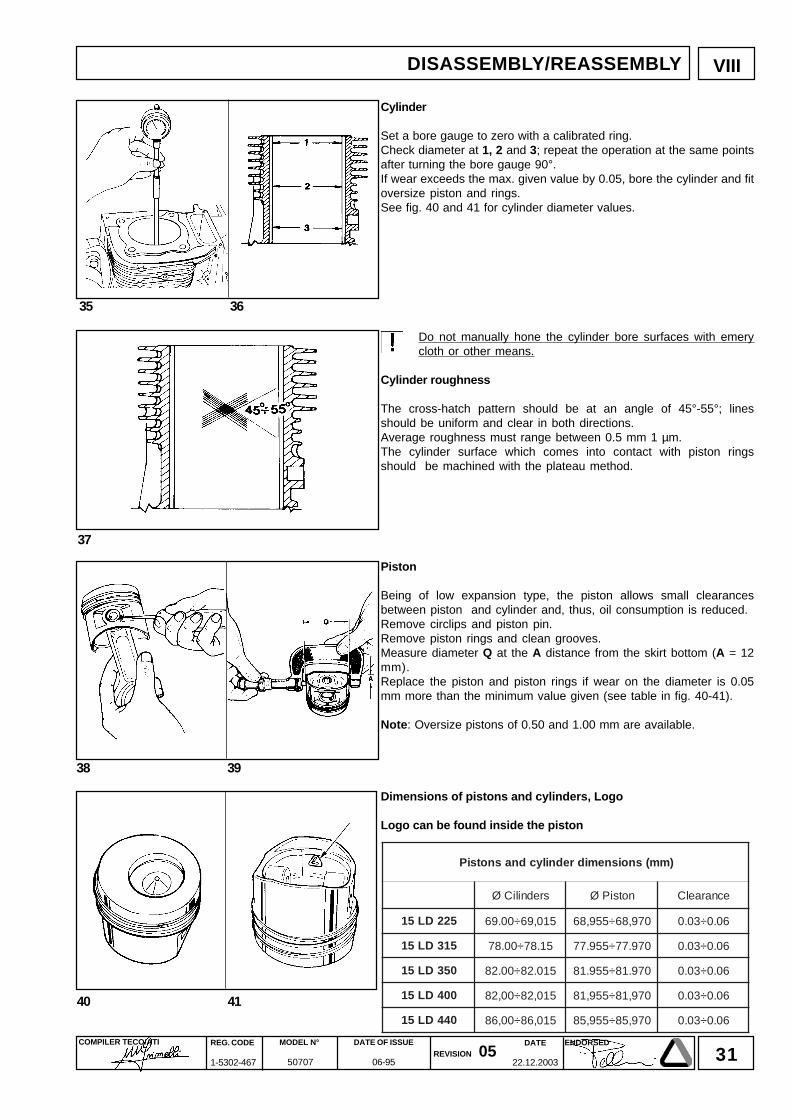
Cylinder
Set a bore gauge to zero with a calibrated ring.Check diameter at 1, 2 and 3; repeat the operation at the same pointsafter turning the bore gauge 90°.If wear exceeds the max. given value by 0.05, bore the cylinder and fitoversize piston and rings.See fig. 40 and 41 for cylinder diameter values.
Do not manually hone the cylinder bore surfaces with emerycloth or other means.
Cylinder roughness
The cross-hatch pattern should be at an angle of 45°-55°; linesshould be uniform and clear in both directions.Average roughness must range between 0.5 mm 1 µm.The cylinder surface which comes into contact with piston ringsshould be machined with the plateau method.
Piston
Being of low expansion type, the piston allows small clearancesbetween piston and cylinder and, thus, oil consumption is reduced.Remove circlips and piston pin.Remove piston rings and clean grooves.Measure diameter Q at the A distance from the skirt bottom (A = 12mm).Replace the piston and piston rings if wear on the diameter is 0.05mm more than the minimum value given (see table in fig. 40-41).
Note: Oversize pistons of 0.50 and 1.00 mm are available.
Dimensions of pistons and cylinders, Logo
Logo can be found inside the piston
DISASSEMBLY/REASSEMBLY
)mm(snoisnemidrednilycdnasnotsiP
sredniliCØ notsiPØ ecnaraelC
522DL51 510,96÷00.96 079,86÷559,86 60.0÷30.0
513DL51 51.87÷00.87 079.77÷559.77 60.0÷30.0
053DL51 510.28÷00.28 079.18÷559.18 60.0÷30.0
004DL51 510,28÷00,28 079,18÷559,18 60.0÷30.0
044DL51 510,68÷00,68 079,58÷559,58 60.0÷30.0
32DATE
22.12.2003
COMPILER TECO/ATI REG. CODE
1-5302-467
MODEL N°
50707
DATE OF ISSUE
06-95REVISION 05
ENDORSED
VIII DISASSEMBLY/REASSEMBLY
33DATE
22.12.2003
COMPILER TECO/ATI REG. CODE
1-5302-467
MODEL N°
50707
DATE OF ISSUE
06-95REVISION 05
ENDORSED
42
VIII
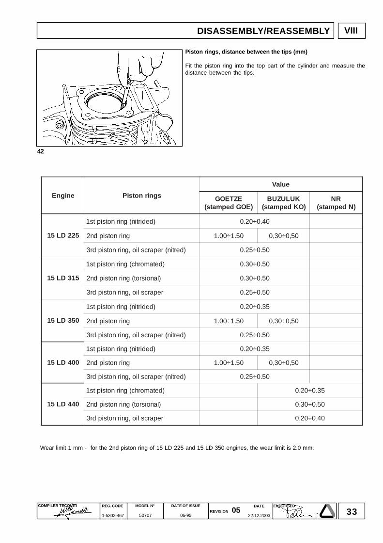
Piston rings, distance between the tips (mm)
Fit the piston ring into the top part of the cylinder and measure thedistance between the tips.
enignE sgnirnotsiP
eulaV
EZTEOG)EOGdepmats(
KULUZUB)OKdepmats(
RN)Ndepmats(
522DL51
)dedirtin(gnirnotsipts1 04.0÷02.0
gnirnotsipdn2 05.1÷00.1 05,0÷03,0
)dertin(reparcslio,gnirnotsipdr3 05.0÷52.0
513DL51
)detamorhc(gnirnotsipts1 05.0÷03.0
)lanoisrot(gnirnotsipdn2 05.0÷03.0
reparcslio,gnirnotsipdr3 05.0÷52.0
053DL51
)dedirtin(gnirnotsipts1 53.0÷02.0
gnirnotsipdn2 05.1÷00.1 05,0÷03,0
)dertin(reparcslio,gnirnotsipdr3 05.0÷52.0
004DL51
)dedirtin(gnirnotsipts1 53.0÷02.0
gnirnotsipdn2 05.1÷00.1 05,0÷03,0
)dertin(reparcslio,gnirnotsipdr3 05.0÷52.0
044DL51
)detamorhc(gnirnotsipts1 53.0÷02.0
)lanoisrot(gnirnotsipdn2 05.0÷03.0
reparcslio,gnirnotsipdr3 04.0÷02.0
Wear limit 1 mm - for the 2nd piston ring of 15 LD 225 and 15 LD 350 engines, the wear limit is 2.0 mm.
DISASSEMBLY/REASSEMBLY
34DATE
22.12.2003
COMPILER TECO/ATI REG. CODE
1-5302-467
MODEL N°
50707
DATE OF ISSUE
06-95REVISION 05
ENDORSED
43 44
VIII
45
46
47
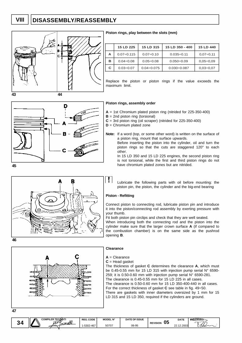
522DL51 513DL51 004-053DL51 044DL51
A 511.0÷70.0 01.0÷70.0 11.0÷530.0 11,0÷70,0
B 80.0÷40.0 80.0÷50.0 90.0÷050.0 90,0÷50,0
C 70.0÷30.0 570.0÷40.0 780.0÷030.0 70,0÷30,0
DISASSEMBLY/REASSEMBLY
Piston rings, play between the slots (mm)
Replace the piston or piston rings if the value exceeds themaximum limit.
Piston rings, assembly order
A = 1st Chromium plated piston ring (nitrided for 225-350-400)B = 2nd piston ring (torsional)C = 3rd piston ring (oil scraper) (nitrided for 225-350-400)D = Chromium plated zone
Note: If a word (top, or some other word) is written on the surface ofa piston ring, mount that surface upwards.Before inserting the piston into the cylinder, oil and turn thepiston rings so that the cuts are staggered 120° to eachother.In 15 LD 350 and 15 LD 225 engines, the second piston ringis not torsional, while the first and third piston rings do nothave chromium plated zones but are nitrided.
Lubricate the following parts with oil before mounting: thepiston pin, the piston, the cylinder and the big-end bearing
Piston - Refitting
Connect piston to connecting rod, lubricate piston pin and introduceit into the piston/connecting rod assembly by exerting pressure withyour thumb.Fit both piston pin circlips and check that they are well seated.When introducing both the connecting rod and the piston into thecylinder make sure that the larger crown surface A (if compared tothe combustion chamber) is on the same side as the pushrodopening B.
Clearance
A = ClearanceC = Head gasketThe thickness of gasket C determines the clearance A, which mustbe 0.45-0.55 mm for 15 LD 315 with injection pump serial N° 6590-259; it is 0.50-0.60 mm with injection pump serial N° 6590-281.The clearance is 0.45-0.55 mm for 15 LD 225 in all cases.The clearance is 0.50-0.60 mm for 15 LD 350-400-440 in all cases.For the correct thickness of gasket C see table in fig. 49÷50.There are gaskets with inner diameters oversized by 1 mm for 15LD 315 and 15 LD 350, required if the cylinders are ground.
35DATE
22.12.2003
COMPILER TECO/ATI REG. CODE
1-5302-467
MODEL N°
50707
DATE OF ISSUE
06-95REVISION 05
ENDORSED
48
VIII
49 50
DISASSEMBLY/REASSEMBLY
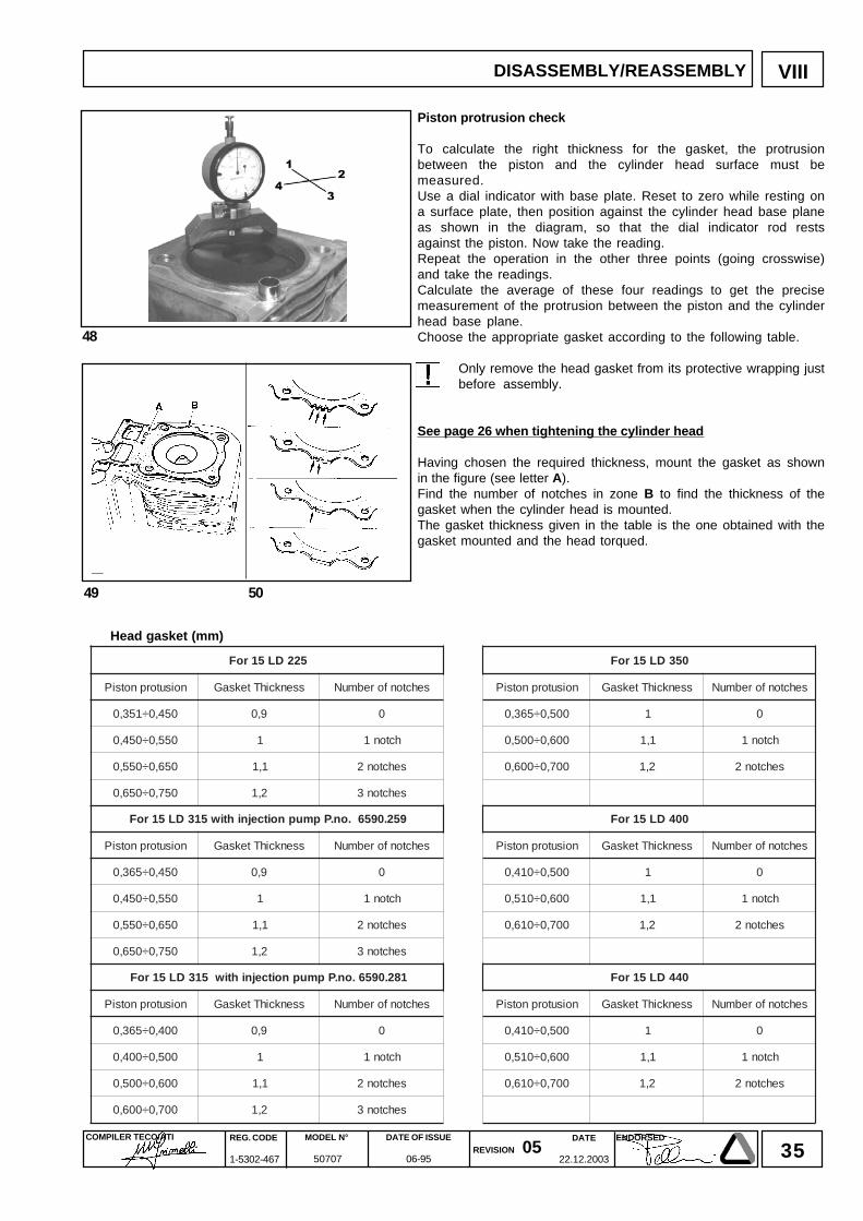
Piston protrusion check
To calculate the right thickness for the gasket, the protrusionbetween the piston and the cylinder head surface must bemeasured.Use a dial indicator with base plate. Reset to zero while resting ona surface plate, then position against the cylinder head base planeas shown in the diagram, so that the dial indicator rod restsagainst the piston. Now take the reading.Repeat the operation in the other three points (going crosswise)and take the readings.Calculate the average of these four readings to get the precisemeasurement of the protrusion between the piston and the cylinderhead base plane.Choose the appropriate gasket according to the following table.
Only remove the head gasket from its protective wrapping justbefore assembly.
See page 26 when tightening the cylinder head
Having chosen the required thickness, mount the gasket as shownin the figure (see letter A).Find the number of notches in zone B to find the thickness of thegasket when the cylinder head is mounted.The gasket thickness given in the table is the one obtained with thegasket mounted and the head torqued.
Head gasket (mm)
522DL51roF 053DL51roF
noisutorpnotsiP ssenkcihTteksaG sehctonforebmuN noisutorpnotsiP ssenkcihTteksaG sehctonforebmuN
054,0÷153,0 9,0 0 005,0÷563,0 1 0
055,0÷054,0 1 hcton1 006,0÷005,0 1,1 hcton1
056,0÷055,0 1,1 sehcton2 007,0÷006,0 2,1 sehcton2
057,0÷056,0 2,1 sehcton3
952.0956.on.Ppmupnoitcejnihtiw513DL51roF 004DL51roF
noisutorpnotsiP ssenkcihTteksaG sehctonforebmuN noisutorpnotsiP ssenkcihTteksaG sehctonforebmuN
054,0÷563,0 9,0 0 005,0÷014,0 1 0
055,0÷054,0 1 hcton1 006,0÷015,0 1,1 hcton1
056,0÷055,0 1,1 sehcton2 007,0÷016,0 2,1 sehcton2
057,0÷056,0 2,1 sehcton3
182.0956.on.Ppmupnoitcejnihtiw513DL51roF 044DL51roF
noisutorpnotsiP ssenkcihTteksaG sehctonforebmuN noisutorpnotsiP ssenkcihTteksaG sehctonforebmuN
004,0÷563,0 9,0 0 005,0÷014,0 1 0
005,0÷004,0 1 hcton1 006,0÷015,0 1,1 hcton1
006,0÷005,0 1,1 sehcton2 007,0÷016,0 2,1 sehcton2
007,0÷006,0 2,1 sehcton3
36DATE
22.12.2003
COMPILER TECO/ATI REG. CODE
1-5302-467
MODEL N°
50707
DATE OF ISSUE
06-95REVISION 05
ENDORSED
52
51
VIII
53
54
522DL51 513DL51 053DL51 044-004DL51
A 30,001÷079,99 30,011÷079,901 30,011÷79,901 30,521÷79,421
B 020,02÷010,02 020,02÷010,02 020,22÷010,22 020,32÷010,32
D 000,02÷599,91 000,02÷599,91 000,22÷599,12 000,32÷599,22
)D-B( 520,0÷010,0 520,0÷010,0 520,0÷010,0 520,0÷010,0
)D-B( etimil 50,0 50,0 50,0 50,0
DISASSEMBLY/REASSEMBLY
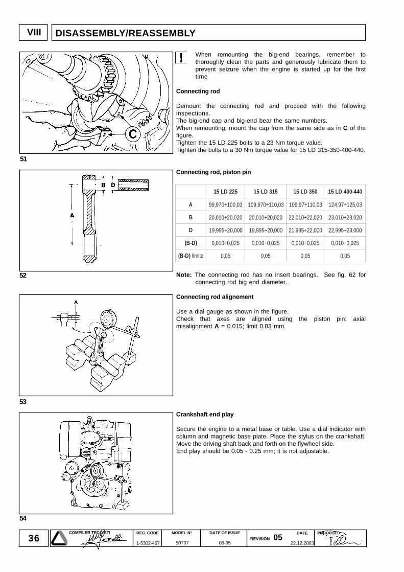
When remounting the big-end bearings, remember tothoroughly clean the parts and generously lubricate them toprevent seizure when the engine is started up for the firsttime
Connecting rod
Demount the connecting rod and proceed with the followinginspections.The big-end cap and big-end bear the same numbers.When remounting, mount the cap from the same side as in C of thefigure.Tighten the 15 LD 225 bolts to a 23 Nm torque value.Tighten the bolts to a 30 Nm torque value for 15 LD 315-350-400-440.
Connecting rod, piston pin
Note: The connecting rod has no insert bearings. See fig. 62 forconnecting rod big end diameter.
Connecting rod alignement
Use a dial gauge as shown in the figure.Check that axes are aligned using the piston pin; axialmisalignment A = 0.015; limit 0.03 mm.
Crankshaft end play
Secure the engine to a metal base or table. Use a dial indicator withcolumn and magnetic base plate. Place the stylus on the crankshaft.Move the driving shaft back and forth on the flywheel side.End play should be 0.05 - 0.25 mm; it is not adjustable.
37DATE
22.12.2003
COMPILER TECO/ATI REG. CODE
1-5302-467
MODEL N°
50707
DATE OF ISSUE
06-95REVISION 05
ENDORSED
57
55 56
VIII
58
59 60
DISASSEMBLY/REASSEMBLY
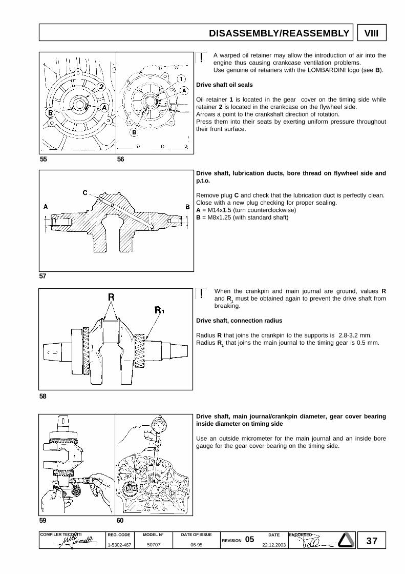
A warped oil retainer may allow the introduction of air into theengine thus causing crankcase ventilation problems.Use genuine oil retainers with the LOMBARDINI logo (see B).
Drive shaft oil seals
Oil retainer 1 is located in the gear cover on the timing side whileretainer 2 is located in the crankcase on the flywheel side.Arrows a point to the crankshaft direction of rotation.Press them into their seats by exerting uniform pressure throughouttheir front surface.
Drive shaft, lubrication ducts, bore thread on flywheel side andp.t.o.
Remove plug C and check that the lubrication duct is perfectly clean.Close with a new plug checking for proper sealing.A = M14x1.5 (turn counterclockwise)B = M8x1.25 (with standard shaft)
When the crankpin and main journal are ground, values Rand R1 must be obtained again to prevent the drive shaft frombreaking.
Drive shaft, connection radius
Radius R that joins the crankpin to the supports is 2.8-3.2 mm.Radius R1 that joins the main journal to the timing gear is 0.5 mm.
Drive shaft, main journal/crankpin diameter, gear cover bearinginside diameter on timing side
Use an outside micrometer for the main journal and an inside boregauge for the gear cover bearing on the timing side.
38DATE
22.12.2003
COMPILER TECO/ATI REG. CODE
1-5302-467
MODEL N°
50707
DATE OF ISSUE
06-95REVISION 05
ENDORSED
61
VIII
62
522DL51 053-513DL51 044-004DL51
D 640,43÷030,43 640,83÷030,83 640,04÷030,04
E 050,53÷030,53 050,53÷030,53 050,04÷030,04
G 610,54÷000,54 610,54÷000,54 910,35÷000,35
H 000,53÷889,43000,53÷889,43002,53÷481,53
000,04÷889,93
I 612,53÷002,53 612,53÷002,53 612,04÷002,04
522DL51 053-513DL51 044-004DL51
)B-D( 260,0÷30,0 260,0÷030,0 260,0030,0
)B-D( etimil 021,0 021,0 021,0
)C-E( 660,0÷30,0 660,0÷030,0 660,0030,0
522DL51 053-513DL51 044-004DL51
)H-A( 520,0÷200,0 420,0÷200,0 420,0÷200,0
)G-F( 650,0÷510,0 650,0÷510,0 650,0÷510,0
)I-L( 650,0÷420,0 650,0÷420,0 650,0÷420,0
DISASSEMBLY/REASSEMBLY
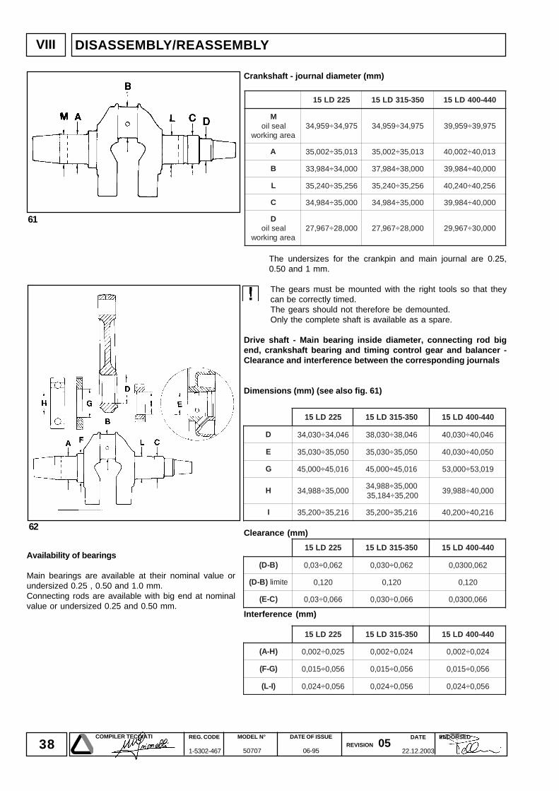
Crankshaft - journal diameter (mm)
The undersizes for the crankpin and main journal are 0.25,0.50 and 1 mm.
The gears must be mounted with the right tools so that theycan be correctly timed.The gears should not therefore be demounted.Only the complete shaft is available as a spare.
Drive shaft - Main bearing inside diameter, connecting rod bigend, crankshaft bearing and timing control gear and balancer -Clearance and interference between the corresponding journals
Dimensions (mm) (see also fig. 61)
Clearance (mm)
Interference (mm)
Availability of bearings
Main bearings are available at their nominal value orundersized 0.25 , 0.50 and 1.0 mm.Connecting rods are available with big end at nominalvalue or undersized 0.25 and 0.50 mm.
522DL51 053-513DL51 044-004DL51
Mlaeslio
aeragnikrow579,43÷959,43 579,43÷959,43 579,93÷959,93
A 310,53÷200,53 310,53÷200,53 310,04÷200,04
B 000,43÷489,33 000,83÷489,73 000,04÷489,93
L 652,53÷042,53 652,53÷042,53 652,04÷042,04
C 000,53÷489,43 000,53÷489,43 000,04÷489,93
Dlaeslio
aeragnikrow000,82÷769,72 000,82÷769,72 000,03÷769,92
39DATE
22.12.2003
COMPILER TECO/ATI REG. CODE
1-5302-467
MODEL N°
50707
DATE OF ISSUE
06-95REVISION 05
ENDORSED
64 65
63
VIII
66
67
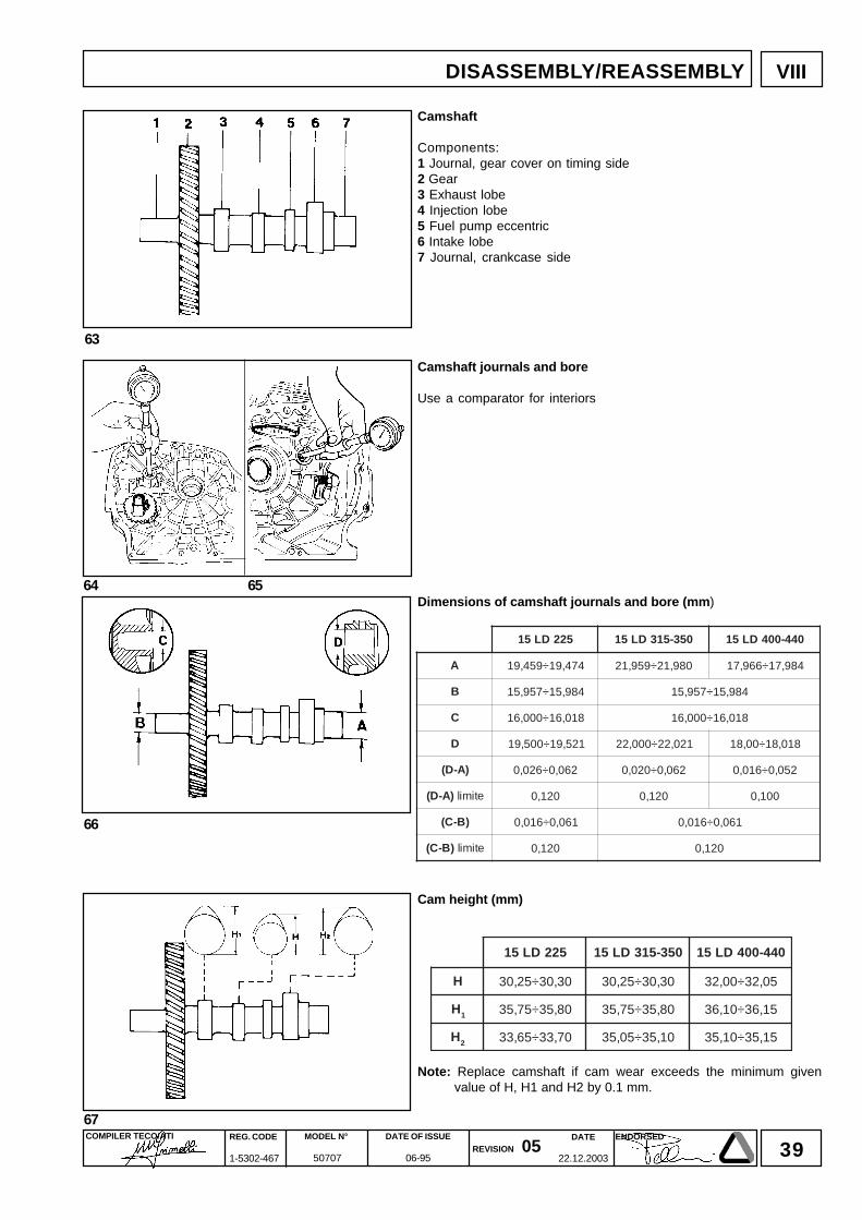
522DL51 053-513DL51 044-004DL51
A 474,91÷954,91 089,12÷959,12 489,71÷669,71
B 489,51÷759,51 489,51÷759,51
C 810,61÷000,61 810,61÷000,61
D 125,91÷005,91 120,22÷000,22 810,81÷00,81
)A-D( 260,0÷620,0 260,0÷020,0 250,0÷610,0
)A-D( etimil 021,0 021,0 001,0
)B-C( 160,0÷610,0 160,0÷610,0
)B-C( etimil 021,0 021,0
522DL51 053-513DL51 044-004DL51
H 03,03÷52,03 03,03÷52,03 50,23÷00,23
H1 08,53÷57,53 08,53÷57,53 51,63÷01,63
H2 07,33÷56,33 01,53÷50,53 51,53÷01,53
DISASSEMBLY/REASSEMBLY
Camshaft
Components:1 Journal, gear cover on timing side2 Gear3 Exhaust lobe4 Injection lobe5 Fuel pump eccentric6 Intake lobe7 Journal, crankcase side
Camshaft journals and bore
Use a comparator for interiors
Dimensions of camshaft journals and bore (mm)
Cam height (mm)
Note: Replace camshaft if cam wear exceeds the minimum givenvalue of H, H1 and H2 by 0.1 mm.
40DATE
22.12.2003
COMPILER TECO/ATI REG. CODE
1-5302-467
MODEL N°
50707
DATE OF ISSUE
06-95REVISION 05
ENDORSED
68
VIII
68a
68b
68c
A
B
DISASSEMBLY/REASSEMBLY
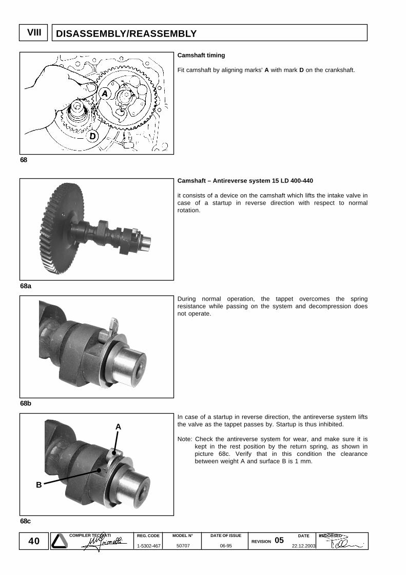
Camshaft timing
Fit camshaft by aligning marks' A with mark D on the crankshaft.
Camshaft – Antireverse system 15 LD 400-440
it consists of a device on the camshaft which lifts the intake valve incase of a startup in reverse direction with respect to normalrotation.
During normal operation, the tappet overcomes the springresistance while passing on the system and decompression doesnot operate.
In case of a startup in reverse direction, the antireverse system liftsthe valve as the tappet passes by. Startup is thus inhibited.
Note: Check the antireverse system for wear, and make sure it iskept in the rest position by the return spring, as shown inpicture 68c. Verify that in this condition the clearancebetween weight A and surface B is 1 mm.
41DATE
22.12.2003
COMPILER TECO/ATI REG. CODE
1-5302-467
MODEL N°
50707
DATE OF ISSUE
06-95REVISION 05
ENDORSED
VIII
69 70
71
72
DISASSEMBLY/REASSEMBLY
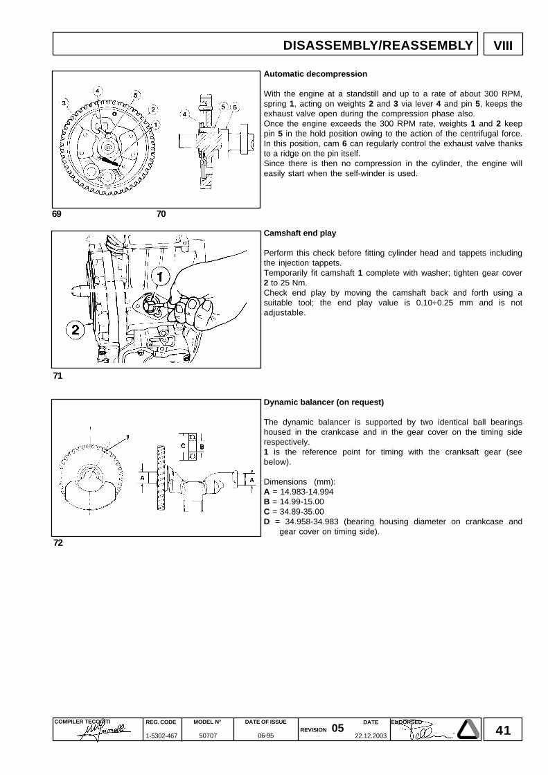
Automatic decompression
With the engine at a standstill and up to a rate of about 300 RPM,spring 1, acting on weights 2 and 3 via lever 4 and pin 5, keeps theexhaust valve open during the compression phase also.Once the engine exceeds the 300 RPM rate, weights 1 and 2 keeppin 5 in the hold position owing to the action of the centrifugal force.In this position, cam 6 can regularly control the exhaust valve thanksto a ridge on the pin itself.Since there is then no compression in the cylinder, the engine willeasily start when the self-winder is used.
Camshaft end play
Perform this check before fitting cylinder head and tappets includingthe injection tappets.Temporarily fit camshaft 1 complete with washer; tighten gear cover2 to 25 Nm.Check end play by moving the camshaft back and forth using asuitable tool; the end play value is 0.10÷0.25 mm and is notadjustable.
Dynamic balancer (on request)
The dynamic balancer is supported by two identical ball bearingshoused in the crankcase and in the gear cover on the timing siderespectively.1 is the reference point for timing with the cranksaft gear (seebelow).
Dimensions (mm):A = 14.983-14.994B = 14.99-15.00C = 34.89-35.00D = 34.958-34.983 (bearing housing diameter on crankcase and
gear cover on timing side).

42DATE
22.12.2003
COMPILER TECO/ATI REG. CODE
1-5302-467
MODEL N°
50707
DATE OF ISSUE
06-95REVISION 05
ENDORSED
VIII NOTE
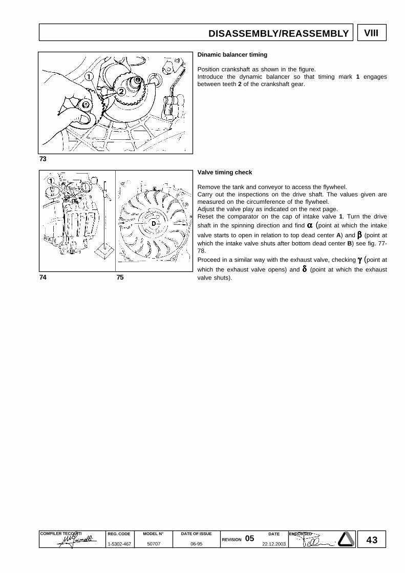
43DATE
22.12.2003
COMPILER TECO/ATI REG. CODE
1-5302-467
MODEL N°
50707
DATE OF ISSUE
06-95REVISION 05
ENDORSED
VIII
74 75
73
DISASSEMBLY/REASSEMBLY
Dinamic balancer timing
Position crankshaft as shown in the figure.Introduce the dynamic balancer so that timing mark 1 engagesbetween teeth 2 of the crankshaft gear.
Valve timing check
Remove the tank and conveyor to access the flywheel.Carry out the inspections on the drive shaft. The values given aremeasured on the circumference of the flywheel.Adjust the valve play as indicated on the next page.Reset the comparator on the cap of intake valve 1. Turn the drive
shaft in the spinning direction and find ααααα (point at which the intake
valve starts to open in relation to top dead center A) and β β β β β (point atwhich the intake valve shuts after bottom dead center B) see fig. 77-78.
Proceed in a similar way with the exhaust valve, checking γγγγγ (point at
which the exhaust valve opens) and δδδδδ (point at which the exhaustvalve shuts).
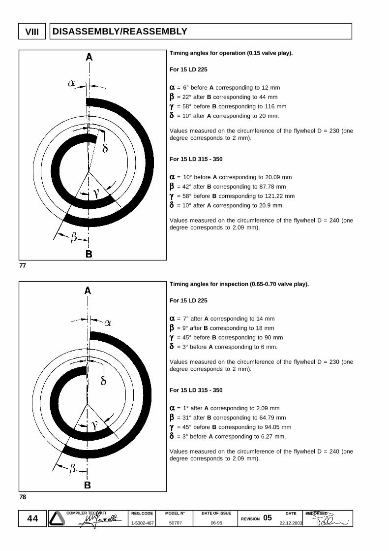
44DATE
22.12.2003
COMPILER TECO/ATI REG. CODE
1-5302-467
MODEL N°
50707
DATE OF ISSUE
06-95REVISION 05
ENDORSED
VIII
77
78
DISASSEMBLY/REASSEMBLY
Timing angles for operation (0.15 valve play).
For 15 LD 225
ααααα = 6° before A corresponding to 12 mm
βββββ = 22° after B corresponding to 44 mm
γγγγγ = 58° before B corresponding to 116 mm
δδδδδ = 10° after A corresponding to 20 mm.
Values measured on the circumference of the flywheel D = 230 (onedegree corresponds to 2 mm).
For 15 LD 315 - 350
ααααα = 10° before A corresponding to 20.09 mm
βββββ = 42° after B corresponding to 87.78 mm
γγγγγ = 58° before B corresponding to 121.22 mm
δδδδδ = 10° after A corresponding to 20.9 mm.
Values measured on the circumference of the flywheel D = 240 (onedegree corresponds to 2.09 mm).
Timing angles for inspection (0.65-0.70 valve play).
For 15 LD 225
ααααα = 7° after A corresponding to 14 mm
βββββ = 9° after B corresponding to 18 mm
γγγγγ = 45° before B corresponding to 90 mm
δδδδδ = 3° before A corresponding to 6 mm.
Values measured on the circumference of the flywheel D = 230 (onedegree corresponds to 2 mm).
For 15 LD 315 - 350
ααααα = 1° after A corresponding to 2.09 mm
βββββ = 31° after B corresponding to 64.79 mm
γγγγγ = 45° before B corresponding to 94.05 mm
δδδδδ = 3° before A corresponding to 6.27 mm.
Values measured on the circumference of the flywheel D = 240 (onedegree corresponds to 2.09 mm).
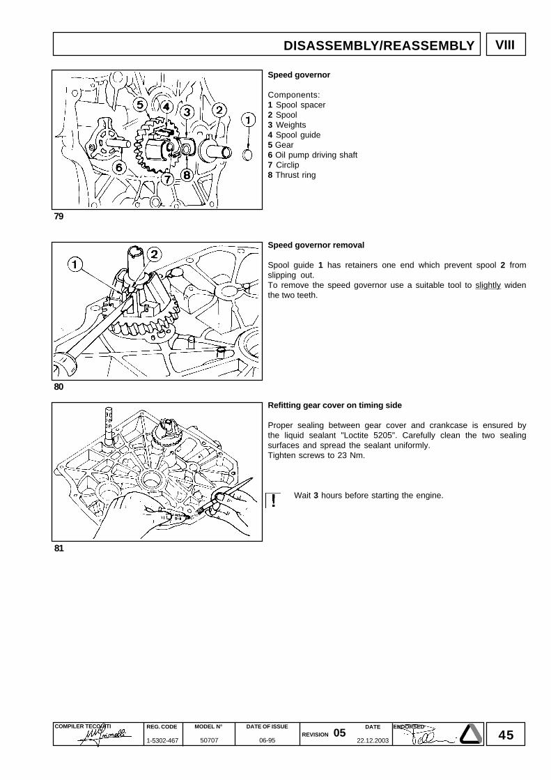
45DATE
22.12.2003
COMPILER TECO/ATI REG. CODE
1-5302-467
MODEL N°
50707
DATE OF ISSUE
06-95REVISION 05
ENDORSED
VIII
79
80
81
DISASSEMBLY/REASSEMBLY
Speed governor
Components:1 Spool spacer2 Spool3 Weights4 Spool guide5 Gear6 Oil pump driving shaft7 Circlip8 Thrust ring
Speed governor removal
Spool guide 1 has retainers one end which prevent spool 2 fromslipping out.To remove the speed governor use a suitable tool to slightly widenthe two teeth.
Refitting gear cover on timing side
Proper sealing between gear cover and crankcase is ensured bythe liquid sealant "Loctite 5205". Carefully clean the two sealingsurfaces and spread the sealant uniformly.Tighten screws to 23 Nm.
Wait 3 hours before starting the engine.
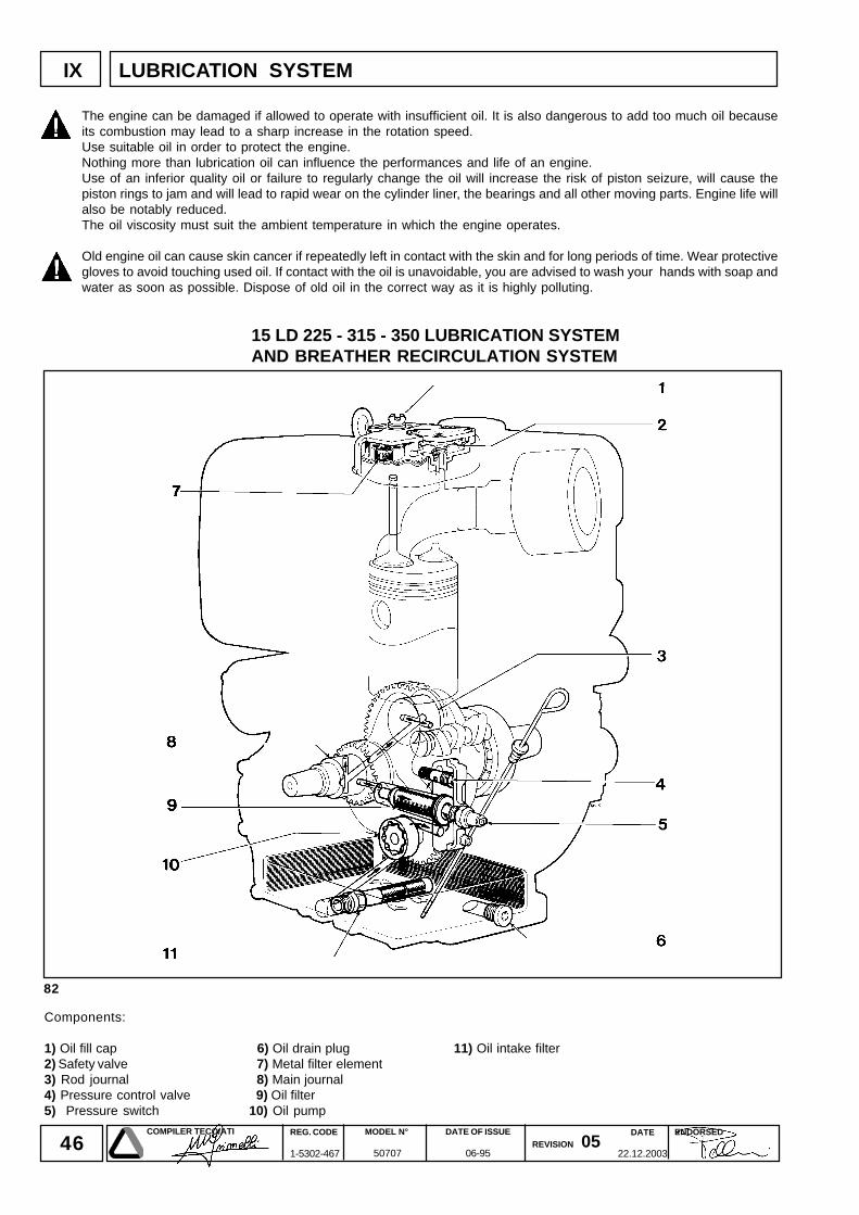
46DATE
22.12.2003
COMPILER TECO/ATI REG. CODE
1-5302-467
MODEL N°
50707
DATE OF ISSUE
06-95REVISION 05
ENDORSED
82
IX
15 LD 225 - 315 - 350 LUBRICATION SYSTEMAND BREATHER RECIRCULATION SYSTEM
LUBRICATION SYSTEM
Components:
1) Oil fill cap 6) Oil drain plug 11) Oil intake filter2) Safety valve 7) Metal filter element3) Rod journal 8) Main journal4) Pressure control valve 9) Oil filter5) Pressure switch 10) Oil pump
The engine can be damaged if allowed to operate with insufficient oil. It is also dangerous to add too much oil becauseits combustion may lead to a sharp increase in the rotation speed.Use suitable oil in order to protect the engine.Nothing more than lubrication oil can influence the performances and life of an engine.Use of an inferior quality oil or failure to regularly change the oil will increase the risk of piston seizure, will cause thepiston rings to jam and will lead to rapid wear on the cylinder liner, the bearings and all other moving parts. Engine life willalso be notably reduced.The oil viscosity must suit the ambient temperature in which the engine operates.
Old engine oil can cause skin cancer if repeatedly left in contact with the skin and for long periods of time. Wear protectivegloves to avoid touching used oil. If contact with the oil is unavoidable, you are advised to wash your hands with soap andwater as soon as possible. Dispose of old oil in the correct way as it is highly polluting.
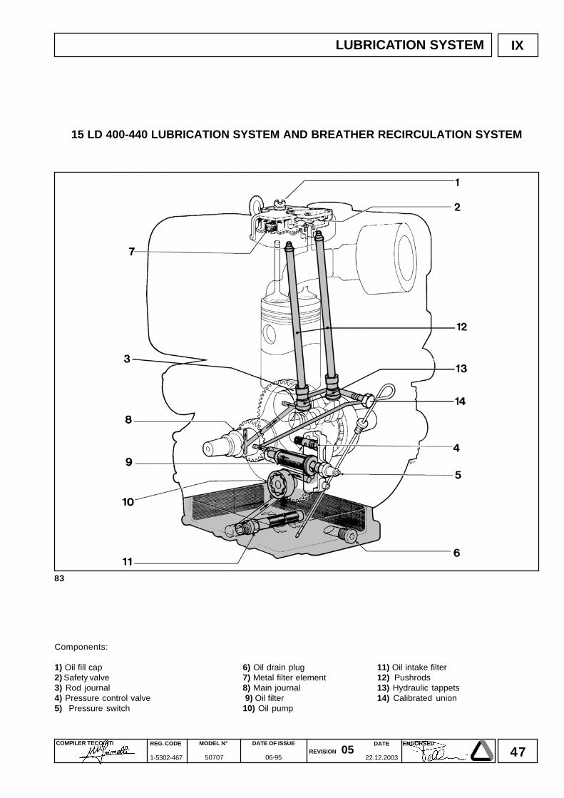
47DATE
22.12.2003
COMPILER TECO/ATI REG. CODE
1-5302-467
MODEL N°
50707
DATE OF ISSUE
06-95REVISION 05
ENDORSED
83
IX LUBRICATION SYSTEM
15 LD 400-440 LUBRICATION SYSTEM AND BREATHER RECIRCULATION SYSTEM
Components:
1) Oil fill cap 6) Oil drain plug 11) Oil intake filter2) Safety valve 7) Metal filter element 12) Pushrods3) Rod journal 8) Main journal 13) Hydraulic tappets4) Pressure control valve 9) Oil filter 14) Calibrated union5) Pressure switch 10) Oil pump
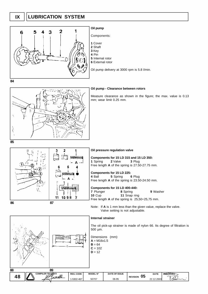
48DATE
22.12.2003
COMPILER TECO/ATI REG. CODE
1-5302-467
MODEL N°
50707
DATE OF ISSUE
06-95REVISION 05
ENDORSED
88 89
84
85
86 87
IX
Oil pump
Components:
1 Cover2 Shaft3 Key4 Pin5 Internal rotor6 External rotor
Oil pump delivery at 3000 rpm is 5.8 l/min.
Oil pump - Clearance between rotors
Measure clearance as shown in the figure; the max. value is 0.13mm; wear limit 0.25 mm.
Oil pressure regulation valve
Components for 15 LD 315 and 15 LD 350:1 Spring 2 Valve 3 PlugFree length A of the spring is 27.50-27.75 mm.
Components for 15 LD 225:4 Ball 5 Spring 6 PlugFree length A of the spring is 23.50-24.50 mm.
Components for 15 LD 400-440:7 Plunger 8 Spring 9 Washer10 Cup 11 Snap ringFree length A of the spring is 25,50÷25,75 mm.
Note: If A is 1 mm less than the given value, replace the valve.Valve setting is not adjustable.
Internal strainer
The oil pick-up strainer is made of nylon 66. Its degree of filtration is500 µm.
Dimensions (mm):A = M16x1.5B = 64C = 102D = 12
LUBRICATION SYSTEM
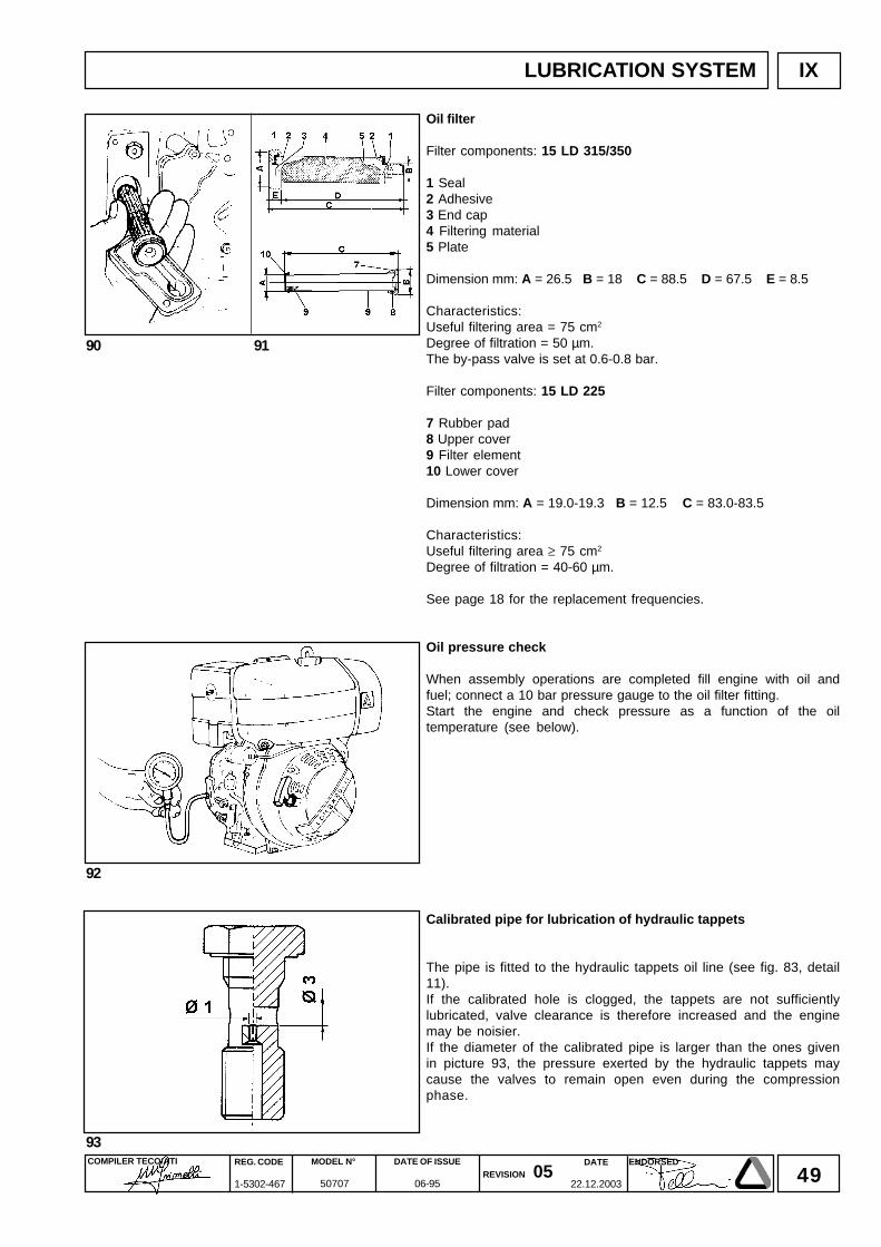
49DATE
22.12.2003
COMPILER TECO/ATI REG. CODE
1-5302-467
MODEL N°
50707
DATE OF ISSUE
06-95REVISION 05
ENDORSED
90 91
92
IX
93
Oil filter
Filter components: 15 LD 315/350
1 Seal2 Adhesive3 End cap4 Filtering material5 Plate
Dimension mm: A = 26.5 B = 18 C = 88.5 D = 67.5 E = 8.5
Characteristics:Useful filtering area = 75 cm2
Degree of filtration = 50 µm.The by-pass valve is set at 0.6-0.8 bar.
Filter components: 15 LD 225
7 Rubber pad8 Upper cover9 Filter element10 Lower cover
Dimension mm: A = 19.0-19.3 B = 12.5 C = 83.0-83.5
Characteristics:Useful filtering area ≥ 75 cm2
Degree of filtration = 40-60 µm.
See page 18 for the replacement frequencies.
Oil pressure check
When assembly operations are completed fill engine with oil andfuel; connect a 10 bar pressure gauge to the oil filter fitting.Start the engine and check pressure as a function of the oiltemperature (see below).
Calibrated pipe for lubrication of hydraulic tappets
The pipe is fitted to the hydraulic tappets oil line (see fig. 83, detail11).If the calibrated hole is clogged, the tappets are not sufficientlylubricated, valve clearance is therefore increased and the enginemay be noisier.If the diameter of the calibrated pipe is larger than the ones givenin picture 93, the pressure exerted by the hydraulic tappets maycause the valves to remain open even during the compressionphase.
LUBRICATION SYSTEM
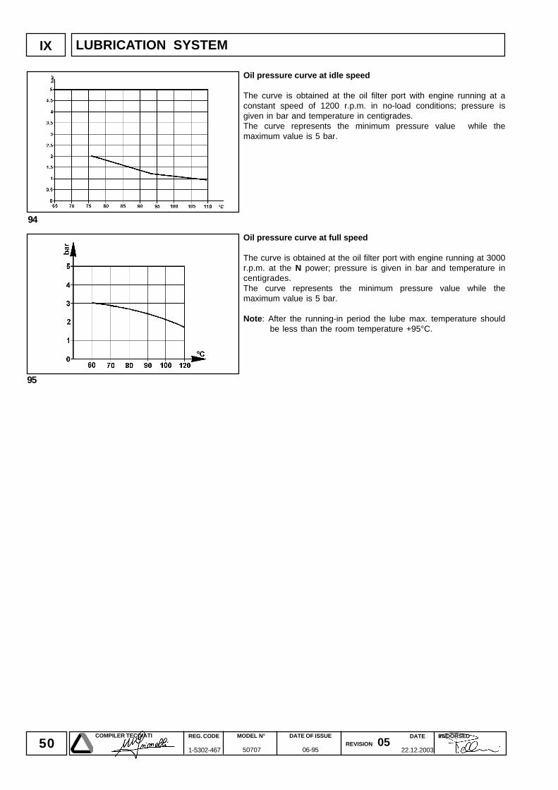
50DATE
22.12.2003
COMPILER TECO/ATI REG. CODE
1-5302-467
MODEL N°
50707
DATE OF ISSUE
06-95REVISION 05
ENDORSED
94
95
IX LUBRICATION SYSTEM
Oil pressure curve at idle speed
The curve is obtained at the oil filter port with engine running at aconstant speed of 1200 r.p.m. in no-load conditions; pressure isgiven in bar and temperature in centigrades.The curve represents the minimum pressure value while themaximum value is 5 bar.
Oil pressure curve at full speed
The curve is obtained at the oil filter port with engine running at 3000r.p.m. at the N power; pressure is given in bar and temperature incentigrades.The curve represents the minimum pressure value while themaximum value is 5 bar.
Note: After the running-in period the lube max. temperature shouldbe less than the room temperature +95°C.
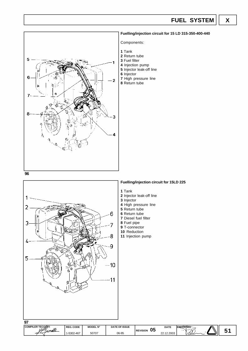
51DATE
22.12.2003
COMPILER TECO/ATI REG. CODE
1-5302-467
MODEL N°
50707
DATE OF ISSUE
06-95REVISION 05
ENDORSED
X
96
97
Fuelling/injection circuit for 15 LD 315-350-400-440
Components:
1 Tank2 Return tube3 Fuel filter4 Injection pump5 Injector leak-off line6 Injector7 High pressure line8 Return tube
Fuelling/injection circuit for 15LD 225
1 Tank2 Injector leak-off line3 Injector4 High pressure line5 Return tube6 Return tube7 Diesel fuel filter8 Fuel pipe9 T-connector10 Reduction11 Injection pump
FUEL SYSTEM
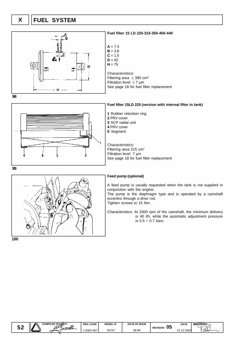
52DATE
22.12.2003
COMPILER TECO/ATI REG. CODE
1-5302-467
MODEL N°
50707
DATE OF ISSUE
06-95REVISION 05
ENDORSED
100
98
X
99
Fuel filter 15 LD 225-315-350-400-440
A = 7.3B = 3.8C = 1.5D = 42H = 75
Characteristics:Filtering area ≥ 390 cm²Filtration level ≤ 7 µmSee page 18 for fuel filter replacement
Fuel filter 15LD 225 (version with internal filter in tank)
1 Rubber retention ring2 PRV cover3 SCP radial unit4 PRV cover5 Segment
Characteristics:Filtering area 215 cm2
Filtration level 7 µmSee page 18 for fuel filter replacement
Feed pump (optional)
A feed pump is usually requested when the tank is not supplied inconjunction with the engine.The pump is the diaphragm type and is operated by a camshafteccentric through a drive rod.Tighten screws to 15 Nm.
Characteristics: At 2000 rpm of the camshaft, the minimum deliveryis 40 l/h, while the automatic adjustment pressureis 0.5 ÷ 0.7 bars.
FUEL SYSTEM
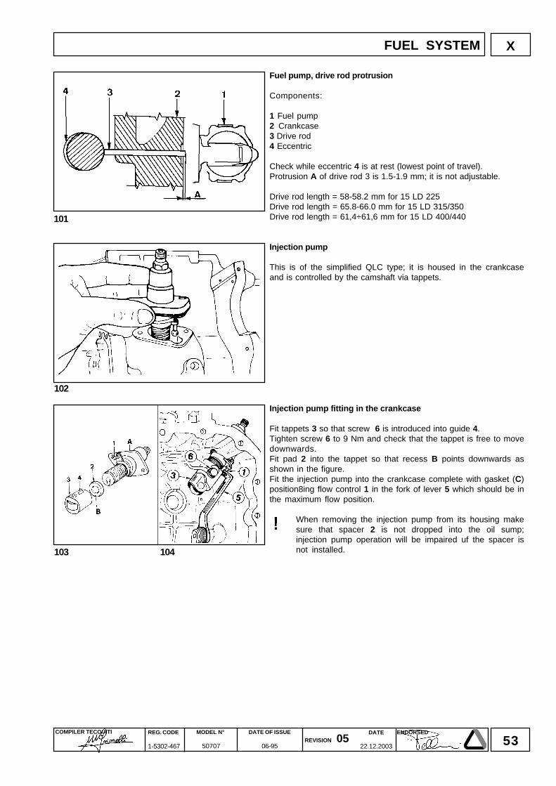
53DATE
22.12.2003
COMPILER TECO/ATI REG. CODE
1-5302-467
MODEL N°
50707
DATE OF ISSUE
06-95REVISION 05
ENDORSED
X
101
102
103 104
Fuel pump, drive rod protrusion
Components:
1 Fuel pump2 Crankcase3 Drive rod4 Eccentric
Check while eccentric 4 is at rest (lowest point of travel).Protrusion A of drive rod 3 is 1.5-1.9 mm; it is not adjustable.
Drive rod length = 58-58.2 mm for 15 LD 225Drive rod length = 65.8-66.0 mm for 15 LD 315/350Drive rod length = 61,4÷61,6 mm for 15 LD 400/440
Injection pump
This is of the simplified QLC type; it is housed in the crankcaseand is controlled by the camshaft via tappets.
Injection pump fitting in the crankcase
Fit tappets 3 so that screw 6 is introduced into guide 4.Tighten screw 6 to 9 Nm and check that the tappet is free to movedownwards.Fit pad 2 into the tappet so that recess B points downwards asshown in the figure.Fit the injection pump into the crankcase complete with gasket (C)position8ing flow control 1 in the fork of lever 5 which should be inthe maximum flow position.
When removing the injection pump from its housing makesure that spacer 2 is not dropped into the oil sump;injection pump operation will be impaired uf the spacer isnot installed.
FUEL SYSTEM
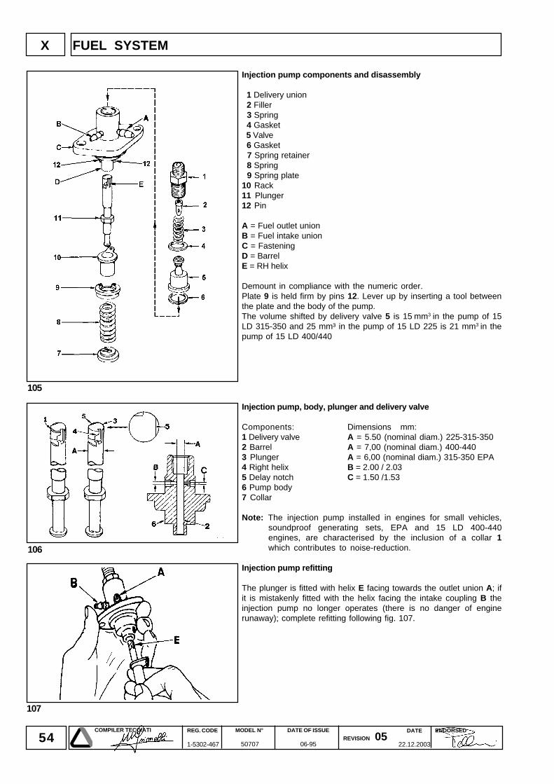
54DATE
22.12.2003
COMPILER TECO/ATI REG. CODE
1-5302-467
MODEL N°
50707
DATE OF ISSUE
06-95REVISION 05
ENDORSED
107
106
105
X
Injection pump components and disassembly
1 Delivery union 2 Filler 3 Spring 4 Gasket 5 Valve 6 Gasket 7 Spring retainer 8 Spring 9 Spring plate10 Rack11 Plunger12 Pin
A = Fuel outlet unionB = Fuel intake unionC = FasteningD = BarrelE = RH helix
Demount in compliance with the numeric order.Plate 9 is held firm by pins 12. Lever up by inserting a tool betweenthe plate and the body of the pump.The volume shifted by delivery valve 5 is 15 mm3 in the pump of 15LD 315-350 and 25 mm³ in the pump of 15 LD 225 is 21 mm3 in thepump of 15 LD 400/440
Injection pump, body, plunger and delivery valve
Components: Dimensions mm:1 Delivery valve A = 5.50 (nominal diam.) 225-315-3502 Barrel A = 7,00 (nominal diam.) 400-4403 Plunger A = 6,00 (nominal diam.) 315-350 EPA4 Right helix B = 2.00 / 2.035 Delay notch C = 1.50 /1.536 Pump body7 Collar
Note: The injection pump installed in engines for small vehicles,soundproof generating sets, EPA and 15 LD 400-440engines, are characterised by the inclusion of a collar 1which contributes to noise-reduction.
Injection pump refitting
The plunger is fitted with helix E facing towards the outlet union A; ifit is mistakenly fitted with the helix facing the intake coupling B theinjection pump no longer operates (there is no danger of enginerunaway); complete refitting following fig. 107.
FUEL SYSTEM
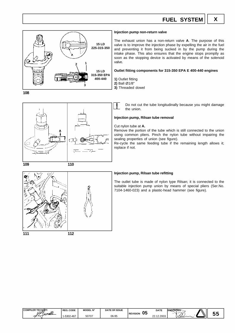
55DATE
22.12.2003
COMPILER TECO/ATI REG. CODE
1-5302-467
MODEL N°
50707
DATE OF ISSUE
06-95REVISION 05
ENDORSED
108
111 112
109 110
X
15 LD225-315-350
15 LD315-350 EPA
400-440
2 1
3
FUEL SYSTEM
Injection pump non-return valve
The exhaust union has a non-return valve A. The purpose of thisvalve is to improve the injection phase by expelling the air in the fueland preventing it from being sucked in by the pump during theintake phase. This also ensures that the engine stops promptly assoon as the stopping device is activated by means of the solenoidvalve.
Outlet fitting components for 315-350 EPA E 400-440 engines
1) Outlet fitting2) Ball Ø1/8"3) Threaded dowel
Do not cut the tube longitudinally because you might damagethe union.
Injection pump, Rilsan tube removal
Cut nylon tube at A.Remove the portion of the tube which is still connected to the unionusing common pliers. Pinch the nylon tube without impairing thesealing properties of union (see figure).Re-cycle the same feeding tube if the remaining length allows it;replace if not.
Injection pump, Rilsan tube refitting
The outlet tube is made of nylon type Rilsan; it is connected to thesuitable injection pump union by means of special pliers (Ser.No.7104-1460-023) and a plastic-head hammer (see figure).
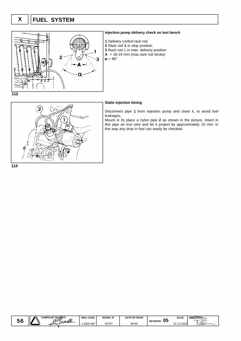
56DATE
22.12.2003
COMPILER TECO/ATI REG. CODE
1-5302-467
MODEL N°
50707
DATE OF ISSUE
06-95REVISION 05
ENDORSED
113
X
114
Injection pump delivery check on test bench
1 Delivery control rack rod2 Rack rod 1 in stop position3 Rack rod 1 in max. delivery positionA = 18-19 mm (max.rack rod stroke)ααααα = 66°
Static injection timing
Disconnect pipe 1 from injection pump and close it, to avoid fuelleakages.Mount in its place a nylon pipe 2 as shown in the picture. Insert inthis pipe an iron wire and let it project by approximately 10 mm: inthis way any drop in fuel can easily be checked.
FUEL SYSTEM
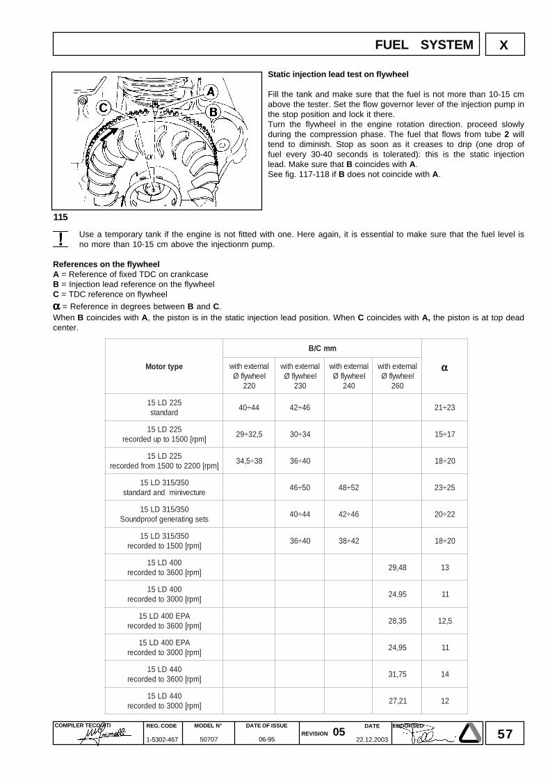
57DATE
22.12.2003
COMPILER TECO/ATI REG. CODE
1-5302-467
MODEL N°
50707
DATE OF ISSUE
06-95REVISION 05
ENDORSED
115
XFUEL SYSTEM
Static injection lead test on flywheel
Fill the tank and make sure that the fuel is not more than 10-15 cmabove the tester. Set the flow governor lever of the injection pump inthe stop position and lock it there.Turn the flywheel in the engine rotation direction. proceed slowlyduring the compression phase. The fuel that flows from tube 2 willtend to diminish. Stop as soon as it creases to drip (one drop offuel every 30-40 seconds is tolerated): this is the static injectionlead. Make sure that B coincides with A.See fig. 117-118 if B does not coincide with A.
Use a temporary tank if the engine is not fitted with one. Here again, it is essential to make sure that the fuel level isno more than 10-15 cm above the injectionm pump.
References on the flywheelA = Reference of fixed TDC on crankcaseB = Injection lead reference on the flywheelC = TDC reference on flywheel
ααααα = Reference in degrees between B and C.When B coincides with A, the piston is in the static injection lead position. When C coincides with A, the piston is at top deadcenter.
epytrotoM
mmC/B
αααααlanretxehtiwleehwylfØ
022
lanretxehtiwleehwylfØ
032
lanretxehtiwleehwylfØ
042
lanretxehtiwleehwylfØ
062
522DL51dradnats
44÷04 64÷24 32÷12
522DL51]mpr[0051otpudedrocer
5,23÷92 43÷03 71÷51
522DL51]mpr[0022ot0051morfdedrocer
83÷5,43 04÷63 02÷81
053/513DL51erutcevinimdnadradnats
05÷64 25÷84 52÷32
053/513DL51stesgnitarenegfoorpdnuoS
44÷04 64÷24 22÷02
053/513DL51]mpr[0051otdedrocer
04÷63 24÷83 02÷81
004DL51]mpr[0063otdedrocer
84,92 31
004DL51]mpr[0003otdedrocer
59,42 11
APE004DL51]mpr[0063otdedrocer
53,82 5,21
APE004DL51]mpr[0003otdedrocer
59,42 11
044DL51]mpr[0063otdedrocer
57,13 41
044DL51]mpr[0003otdedrocer
12,72 21
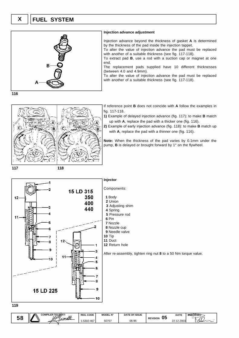
58DATE
22.12.2003
COMPILER TECO/ATI REG. CODE
1-5302-467
MODEL N°
50707
DATE OF ISSUE
06-95REVISION 05
ENDORSED
116
117 118
X
119
FUEL SYSTEM
Injection advance adjustment
Injection advance beyond the thickness of gasket A is determinedby the thickness of the pad inside the injection tappet.To alter the value of injection advance the pad must be replacedwith another of a suitable thickness (see fig. 117-118).To extract pad B, use a rod with a suction cap or magnet at oneend.The replacement pads supplied have 10 different thicknesses(between 4.0 and 4.9mm).To alter the value of injection advance the pad must be replacedwith another of a suitable thickness (see fig. 117-118).
If reference point B does not coincide with A follow the examples in
fig. 117-118.1) Example of delayed injection advance (fig. 117): to make B match
up with A, replace the pad with a thicker one (fig. 116).2) Example of early injection advance (fig. 118): to make B match up
with A, replace the pad with a thinner one (fig. 116).
Note: When the thickness of the pad varies by 0.1mm under thepump, B is delayed or brought forward by 1° on the flywheel.
Injector
Components:
1 Body 2 Union 3 Adjusting shim 4 Spring 5 Pressure rod 6 Pin 7 Nozzle 8 Nozzle cup 9 Needle valve10 Tip11 Duct12 Return hole
After re-assembly, tighten ring nut 8 to a 50 Nm torque value.
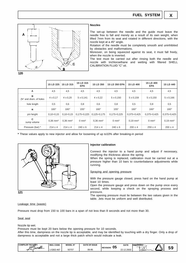
59DATE
22.12.2003
COMPILER TECO/ATI REG. CODE
1-5302-467
MODEL N°
50707
DATE OF ISSUE
06-95REVISION 05
ENDORSED
X
121
120
FUEL SYSTEM
Injector calibration
Connect the injector to a hand pump and adjust if necessary,modifying the thickness above the spring.When the spring is replaced, calibration must be carried out at apressure higher than 10 bars to counterbalance adjustments whilerunning.
Spraying and opening pressure
With the pressure gauge closed, press hard on the hand pump atleast 10 times.Open the pressure gauge and press down on the pump once everysecond, while keeping a check on the spraying process andpressure.The opening pressure must lie between the two values given in thetable. Jets must be uniform and well distributed.
Nozzles
The set-up between the needle and the guide must leave theneedle free to fall and merely as a result of its own weight, whenlifted 7mm from its seat and rotated in different directions, with thenozzle kept at a 45° angle.Rotation of the needle must be completely smooth and uninhibitedby obstacles and malformations.Moreover, on being squeezed against its seat, it must fall freely,when the nozzle is inverted.The test must be carried out after rinsing both the needle andnozzle with trichloroethane and wetting with filtered SHELLCALIBRATION FLUID “C” oil.
522DL51 513DL51513DL51
APE053DL51 APE053DL51 004DL51
004DL51APE
044DL51
A 5,4 5,4 5,4 5,4 5,4 5,4 5,4 5,4
Bselohfo.maiddna°N(
71,0x4 02,0x4 141,0x5 22,0x4 051,0x5 951,0x5 051,0x5 661,0x5
htgneleloh 5,0 6,0 8,0 6,0 8,0 5,0 8,0 5,0
ααααα °061 °061 °551 °061 °551 °061 °061 °061
thgiehnip 51,0÷01,0 51,0÷01,0 522,0÷571,0 571,0÷521,0 522,0÷571,0 524,0÷573,0 524,0÷573,0 524,0÷573,0
Cemulovpmus
³mm63,0 ³mm63,0 ³mm0 ³mm63,0 ³mm0 ³mm91,0 ³mm0 ³mm91,0
*)rab(erusserP 4±412 4±412 6±042 4±412 6±042 4±002 4±952 4±002
Leakage time (waste)
Pressure must drop from 150 to 100 bars in a span of not less than 8 seconds and not more than 30.
Seat seal
Nozzle tip wet.Pressure must be kept 20 bars below the opening pressure for 10 seconds.After this time, dampness on the nozzle tip is acceptable, and may be identified by touching with a dry finger. Only a drop ofdampness is acceptable and not a large thick patch which would indicate a leak.
* These values apply to new injector and allow for loosening of up to10% after breaking-in period

60DATE
22.12.2003
COMPILER TECO/ATI REG. CODE
1-5302-467
MODEL N°
50707
DATE OF ISSUE
06-95REVISION 05
ENDORSED
- NOTE
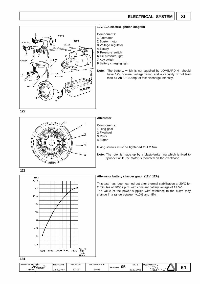
61DATE
22.12.2003
COMPILER TECO/ATI REG. CODE
1-5302-467
MODEL N°
50707
DATE OF ISSUE
06-95REVISION 05
ENDORSED
XI
124
122
123
12V, 12A electric ignition diagram
Components:1 Alternator2 Starter motor3 Voltage regulator4 Battery5 Pressure switch6 Oil pressure light7 Key switch8 Battery charging light
Note: The battery, which is not supplied by LOMBARDINI, shouldhave 12V nominal voltage rating and a capacity of not lessthan 44 Ah / 210 Amp. of fast discharge intensity.
Alternator
Components:1 Ring gear2 Flywheel3 Rotor4 Stator
Fixing screws must be tightened to 1.2 Nm.
Note: The rotor is made up by a plastoferrite ring which is fixed toflywheel while the stator is mounted on the crankcase.
Alternator battery charger graph (12V, 12A)
This test has been carried out after thermal stabilization at 20°C for2 minutes at 3000 r.p.m. with constant battery voltage of 12.5V.The value of the power supplied with reference to the curve maychange in a range between +10% and -5%.
ELECTRICAL SYSTEM
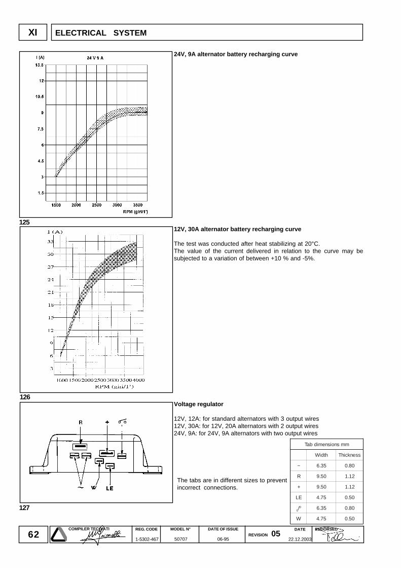
62DATE
22.12.2003
COMPILER TECO/ATI REG. CODE
1-5302-467
MODEL N°
50707
DATE OF ISSUE
06-95REVISION 05
ENDORSED
XI
126
127
125
ELECTRICAL SYSTEM
24V, 9A alternator battery recharging curve
12V, 30A alternator battery recharging curve
The test was conducted after heat stabilizing at 20°C.The value of the current delivered in relation to the curve may besubjected to a variation of between +10 % and -5%.
Voltage regulator
12V, 12A: for standard alternators with 3 output wires12V, 30A: for 12V, 20A alternators with 2 output wires24V, 9A: for 24V, 9A alternators with two output wires
The tabs are in different sizes to preventincorrect connections.
mmsnoisnemidbaT
htdiW ssenkcihT
~ 53.6 08.0
R 05.9 21.1
+ 05.9 21.1
EL 57.4 05.0
0/0 53.6 08.0
W 57.4 05.0
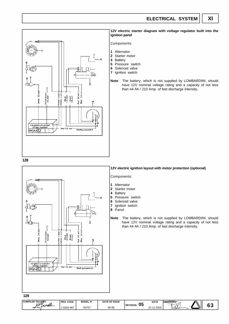
63DATE
22.12.2003
COMPILER TECO/ATI REG. CODE
1-5302-467
MODEL N°
50707
DATE OF ISSUE
06-95REVISION 05
ENDORSED
XI
128
129
ELECTRICAL SYSTEM
12V electric starter diagram with voltage regulator built into theignition panel
Components:
1 Alternator2 Starter motor4 Battery5 Pressure switch6 Solenoid valve7 Ignition switch
Note: The battery, which is not supplied by LOMBARDINI, shouldhave 12V nominal voltage rating and a capacity of not lessthan 44 Ah / 210 Amp. of fast discharge intensity.
12V electric ignition layout with motor protection (optional)
Components:
1 Alternator2 Starter motor4 Battery5 Pressure switch6 Solenoid valve7 Ignition switch8 Panel
Note: The battery, which is not supplied by LOMBARDINI, shouldhave 12V nominal voltage rating and a capacity of not lessthan 44 Ah / 210 Amp. of fast discharge intensity.
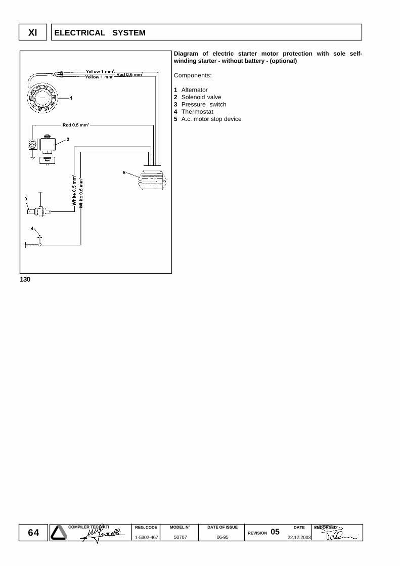
64DATE
22.12.2003
COMPILER TECO/ATI REG. CODE
1-5302-467
MODEL N°
50707
DATE OF ISSUE
06-95REVISION 05
ENDORSED
130
XI ELECTRICAL SYSTEM
Diagram of electric starter motor protection with sole self-winding starter - without battery - (optional)
Components:
1 Alternator2 Solenoid valve3 Pressure switch4 Thermostat5 A.c. motor stop device
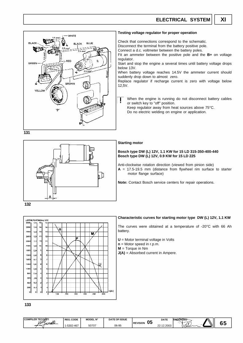
65DATE
22.12.2003
COMPILER TECO/ATI REG. CODE
1-5302-467
MODEL N°
50707
DATE OF ISSUE
06-95REVISION 05
ENDORSED
131
XI
132
133
ELECTRICAL SYSTEM
Testing voltage regulator for proper operation
Check that connections correspond to the schematic.Disconnect the terminal from the battery positive pole.Connect a d.c. voltmeter between the battery poles.Fit an ammeter between the positive pole and the B+ on voltageregulator.Start and stop the engine a several times until battery voltage dropsbelow 13V.When battery voltage reaches 14.5V the ammeter current shouldsuddenly drop down to almost zero.Replace regulator if recharge current is zero with voltage below12,5V.
When the engine is running do not disconnect battery cablesor switch key to "off" position.Keep regulator away from heat sources above 75°C.Do no electric welding on engine or application.
Starting motor
Bosch type DW (L) 12V, 1.1 KW for 15 LD 315-350-400-440Bosch type DW (L) 12V, 0.9 KW for 15 LD 225
Anti-clockwise rotation direction (viewed from pinion side)A = 17.5-19.5 mm (distance from flywheel rim surface to starter
motor flange surface)
Note: Contact Bosch service centers for repair operations.
Characteristic curves for starting motor type DW (L) 12V, 1.1 KW
The curves were obtained at a temperature of -20°C with 66 Ahbattery.
U = Motor terminal voltage in Voltsn = Motor speed in r.p.m.M = Torque in NmJ(A) = Absorbed current in Ampere.
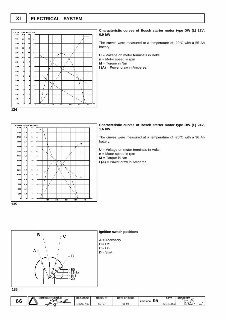
66DATE
22.12.2003
COMPILER TECO/ATI REG. CODE
1-5302-467
MODEL N°
50707
DATE OF ISSUE
06-95REVISION 05
ENDORSED
XI
136
134
135
ELECTRICAL SYSTEM
Characteristic curves of Bosch starter motor type DW (L) 12V,0.9 kW
The curves were measured at a temperature of -20°C with a 55 Ahbattery.
U = Voltage on motor terminals in Volts.n = Motor speed in rpmM = Torque in NmI (A) = Power draw in Amperes.
Characteristic curves of Bosch starter motor type DW (L) 24V,1.6 kW
The curves were measured at a temperature of -20°C with a 36 Ahbattery.
U = Voltage on motor terminals in Volts.n = Motor speed in rpmM = Torque in NmI (A) = Power draw in Amperes..
Ignition switch positions
A = AccessoryB = OffC = OnD = Start
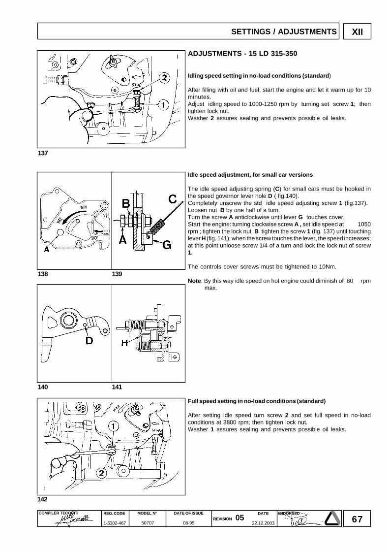
67DATE
22.12.2003
COMPILER TECO/ATI REG. CODE
1-5302-467
MODEL N°
50707
DATE OF ISSUE
06-95REVISION 05
ENDORSED
XII
142
137
140 141
138 139
SETTINGS / ADJUSTMENTS
ADJUSTMENTS - 15 LD 315-350
Idling speed setting in no-load conditions (standard)
After filling with oil and fuel, start the engine and let it warm up for 10minutes.Adjust idling speed to 1000-1250 rpm by turning set screw 1; thentighten lock nut.Washer 2 assures sealing and prevents possible oil leaks.
Idle speed adjustment, for small car versions
The idle speed adjusting spring (C) for small cars must be hooked inthe speed governor lever hole D ( fig.140).Completely unscrew the std idle speed adjusting screw 1 (fig.137).Loosen nut B by one half of a turn.Turn the screw A anticlockwise until lever G touches cover.Start the engine: turning clockwise screw A , set idle speed at 1050rpm ; tighten the lock nut B tighten the screw 1 (fig. 137) until touchinglever H (fig. 141); when the screw touches the lever, the speed increases;at this point unloose screw 1/4 of a turn and lock the lock nut of screw1.
The controls cover screws must be tightened to 10Nm.
Note: By this way idle speed on hot engine could diminish of 80 rpmmax.
Full speed setting in no-load conditions (standard)
After setting idle speed turn screw 2 and set full speed in no-loadconditions at 3800 rpm; then tighten lock nut.Washer 1 assures sealing and prevents possible oil leaks.
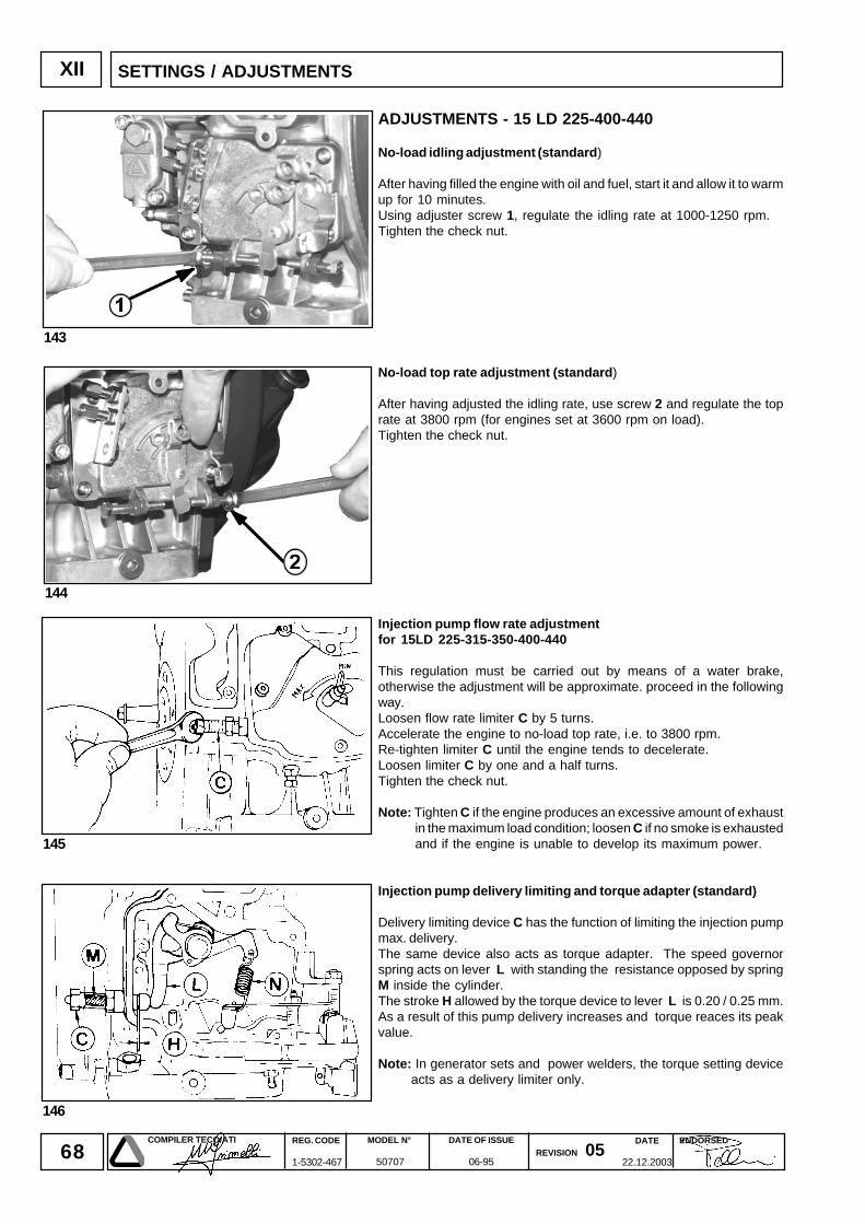
68DATE
22.12.2003
COMPILER TECO/ATI REG. CODE
1-5302-467
MODEL N°
50707
DATE OF ISSUE
06-95REVISION 05
ENDORSED
XII
145
146
143
144
SETTINGS / ADJUSTMENTS
ADJUSTMENTS - 15 LD 225-400-440
No-load idling adjustment (standard)
After having filled the engine with oil and fuel, start it and allow it to warmup for 10 minutes.Using adjuster screw 1, regulate the idling rate at 1000-1250 rpm.Tighten the check nut.
No-load top rate adjustment (standard)
After having adjusted the idling rate, use screw 2 and regulate the toprate at 3800 rpm (for engines set at 3600 rpm on load).Tighten the check nut.
Injection pump flow rate adjustmentfor 15LD 225-315-350-400-440
This regulation must be carried out by means of a water brake,otherwise the adjustment will be approximate. proceed in the followingway.Loosen flow rate limiter C by 5 turns.Accelerate the engine to no-load top rate, i.e. to 3800 rpm.Re-tighten limiter C until the engine tends to decelerate.Loosen limiter C by one and a half turns.Tighten the check nut.
Note: Tighten C if the engine produces an excessive amount of exhaustin the maximum load condition; loosen C if no smoke is exhaustedand if the engine is unable to develop its maximum power.
Injection pump delivery limiting and torque adapter (standard)
Delivery limiting device C has the function of limiting the injection pumpmax. delivery.The same device also acts as torque adapter. The speed governorspring acts on lever L with standing the resistance opposed by springM inside the cylinder.The stroke H allowed by the torque device to lever L is 0.20 / 0.25 mm.As a result of this pump delivery increases and torque reaces its peakvalue.
Note: In generator sets and power welders, the torque setting deviceacts as a delivery limiter only.
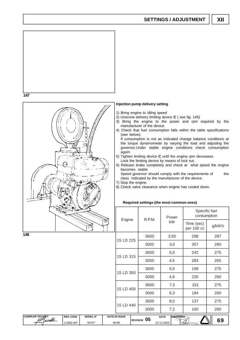
69DATE
22.12.2003
COMPILER TECO/ATI REG. CODE
1-5302-467
MODEL N°
50707
DATE OF ISSUE
06-95REVISION 05
ENDORSED
148
XII
147
SETTINGS / ADJUSTMENT
Injection pump delivery setting
1) Bring engine to idling speed2) Unscrew delivery limiting device C ( see fig. 145)3) Bring the engine to the power and rpm required by the
manufacturer of the device.4) Check that fuel consumption falls within the table specifications
(see below).If consumption is not as indicated change balance conditions atthe torque dynamometer by varying the load and adjusting thegovernor.Under stable engine conditions check consumptionagain.
5) Tighten limiting device C until the engine rpm decreases.Lock the limiting device by means of lock nut.
6) Release brake completely and check at what speed the enginebecomes stableSpeed governor should comply with the requirements of theclass indicated by the manufacturer of the device.
7) Stop the engine.8) Check valve clearance when engine has cooled down.
Required settings (the most common ones)
enignE .M.P.RrewoP
Wk
leufcificepSnoitpmusnoc
)ces(emiTcc001rep
h.Wk/g
522DL510063 05,3 892 782
0003 0,3 753 082
513DL510063 0,5 242 572
0003 5,4 382 562
053DL510063 5,5 891 572
0003 9,4 532 062
004DL510063 3,7 151 572
0003 3,6 481 062
044DL510063 0,8 731 572
0003 2,7 061 062
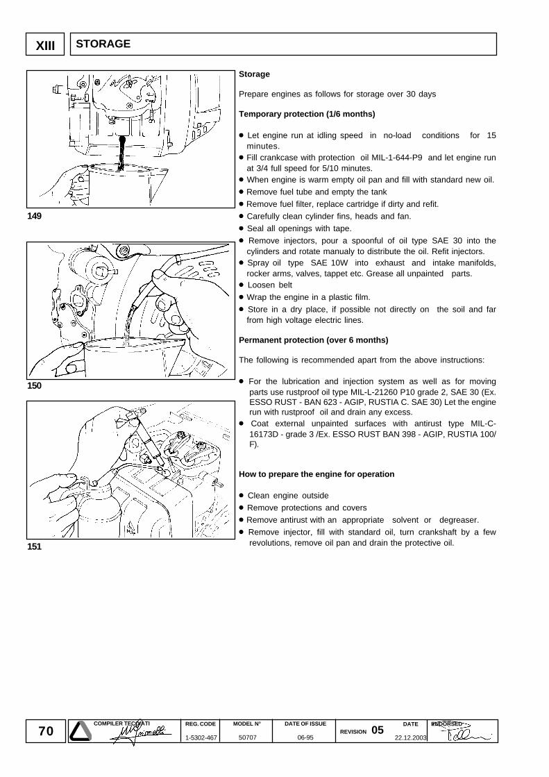
70DATE
22.12.2003
COMPILER TECO/ATI REG. CODE
1-5302-467
MODEL N°
50707
DATE OF ISSUE
06-95REVISION 05
ENDORSED
XIII
149
151
150
STORAGE
Storage
Prepare engines as follows for storage over 30 days
Temporary protection (1/6 months)
• • • • • Let engine run at idling speed in no-load conditions for 15minutes.
• • • • • Fill crankcase with protection oil MIL-1-644-P9 and let engine runat 3/4 full speed for 5/10 minutes.
• • • • • When engine is warm empty oil pan and fill with standard new oil.
• • • • • Remove fuel tube and empty the tank
• • • • • Remove fuel filter, replace cartridge if dirty and refit.
• • • • • Carefully clean cylinder fins, heads and fan.
• • • • • Seal all openings with tape.
• • • • • Remove injectors, pour a spoonful of oil type SAE 30 into thecylinders and rotate manualy to distribute the oil. Refit injectors.
• • • • • Spray oil type SAE 10W into exhaust and intake manifolds,rocker arms, valves, tappet etc. Grease all unpainted parts.
• • • • • Loosen belt
• • • • • Wrap the engine in a plastic film.
• • • • • Store in a dry place, if possible not directly on the soil and farfrom high voltage electric lines.
Permanent protection (over 6 months)
The following is recommended apart from the above instructions:
• • • • • For the lubrication and injection system as well as for movingparts use rustproof oil type MIL-L-21260 P10 grade 2, SAE 30 (Ex.ESSO RUST - BAN 623 - AGIP, RUSTIA C. SAE 30) Let the enginerun with rustproof oil and drain any excess.
• • • • • Coat external unpainted surfaces with antirust type MIL-C-16173D - grade 3 /Ex. ESSO RUST BAN 398 - AGIP, RUSTIA 100/F).
How to prepare the engine for operation
• • • • • Clean engine outside
• • • • • Remove protections and covers
• • • • • Remove antirust with an appropriate solvent or degreaser.
• • • • • Remove injector, fill with standard oil, turn crankshaft by a fewrevolutions, remove oil pan and drain the protective oil.
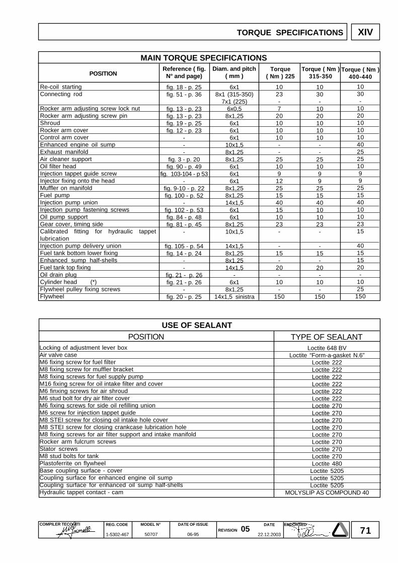
71DATE
22.12.2003
COMPILER TECO/ATI REG. CODE
1-5302-467
MODEL N°
50707
DATE OF ISSUE
06-95REVISION 05
ENDORSED
XIV
1030-
1020101010--
251099
251540101023-
-15-
20-
10-
150
6x18x1 (315-350)
7x1 (225)6x0,5
8x1,256x16x16x1
10x1,58x1,258x1,25
6x16x16x1
8x1,258x1,2514x1,5
6x16x1
8x1,2510x1,5
14x1,58x1,258x1,2514x1,5
-6x1
8x1,2514x1,5 sinistra
fig. 18 - p. 25fig. 51 - p. 36
fig. 13 - p. 23fig. 13 - p. 23fig. 19 - p. 25fig. 12 - p. 23
---
fig. 3 - p. 20fig. 90 - p. 49
fig. 103-104 - p 53-
fig. 9-10 - p. 22fig. 100 - p. 52
-fig. 102 - p. 53fig. 84 - p. 48fig. 81 - p. 45
-
fig. 105 - p. 54fig. 14 - p. 24
--
fig. 21 - p. 26fig. 21 - p. 26
-fig. 20 - p. 25
1023-7
20101010--
25109
12251540151023-
-15-
20-
10-
150
Loctite 648 BVLoctite “Form-a-gasket N.6”
Loctite 222Loctite 222Loctite 222Loctite 222Loctite 222Loctite 222Loctite 270Loctite 270Loctite 270Loctite 270Loctite 270Loctite 270Loctite 270Loctite 270Loctite 480
Loctite 5205Loctite 5205Loctite 5205
MOLYSLIP AS COMPOUND 40
1030-
10201010104025251099
25154010102315
40151520-
1025
150
TORQUE SPECIFICATIONS
POSITIONUSE OF SEALANT
MAIN TORQUE SPECIFICATIONS
TYPE OF SEALANT
Re-coil startingConnecting rod
Rocker arm adjusting screw lock nutRocker arm adjusting screw pinShroudRocker arm coverControl arm coverEnhanced engine oil sumpExhaust manifoldAir cleaner supportOil filter headInjection tappet guide screwInjector fixing onto the headMuffler on manifoldFuel pumpInjection pump unionInjection pump fastening screwsOil pump supportGear cover, timing sideCalibrated fitting for hydraulic tappetlubricationInjection pump delivery unionFuel tank bottom lower fixingEnhanced sump half-shellsFuel tank top fixingOil drain plugCylinder head (*)Flywheel pulley fixing screwsFlywheel
Locking of adjustment lever boxAir valve caseM6 fixing screw for fuel filterM8 fixing screw for muffler bracketM8 fixing screws for fuel supply pumpM16 fixing screw for oil intake filter and coverM6 finxing screws for air shroudM6 stud bolt for dry air filter coverM6 fixing screws for side oil refilling unionM6 screw for injection tappet guideM8 STEI screw for closing oil intake hole coverM8 STEI screw for closing crankcase lubrication holeM8 fixing screws for air filter support and intake manifoldRocker arm fulcrum screwsStator screwsM8 stud bolts for tankPlastoferrite on flywheelBase coupling surface - coverCoupling surface for enhanced engine oil sumpCoupling surface for enhanced oil sump half-shellsHydraulic tappet contact - cam
POSITIONTorque ( Nm )
315-350Diam. and pitch
( mm )Reference ( fig.
N° and page)Torque
( Nm ) 225Torque ( Nm )
400-440
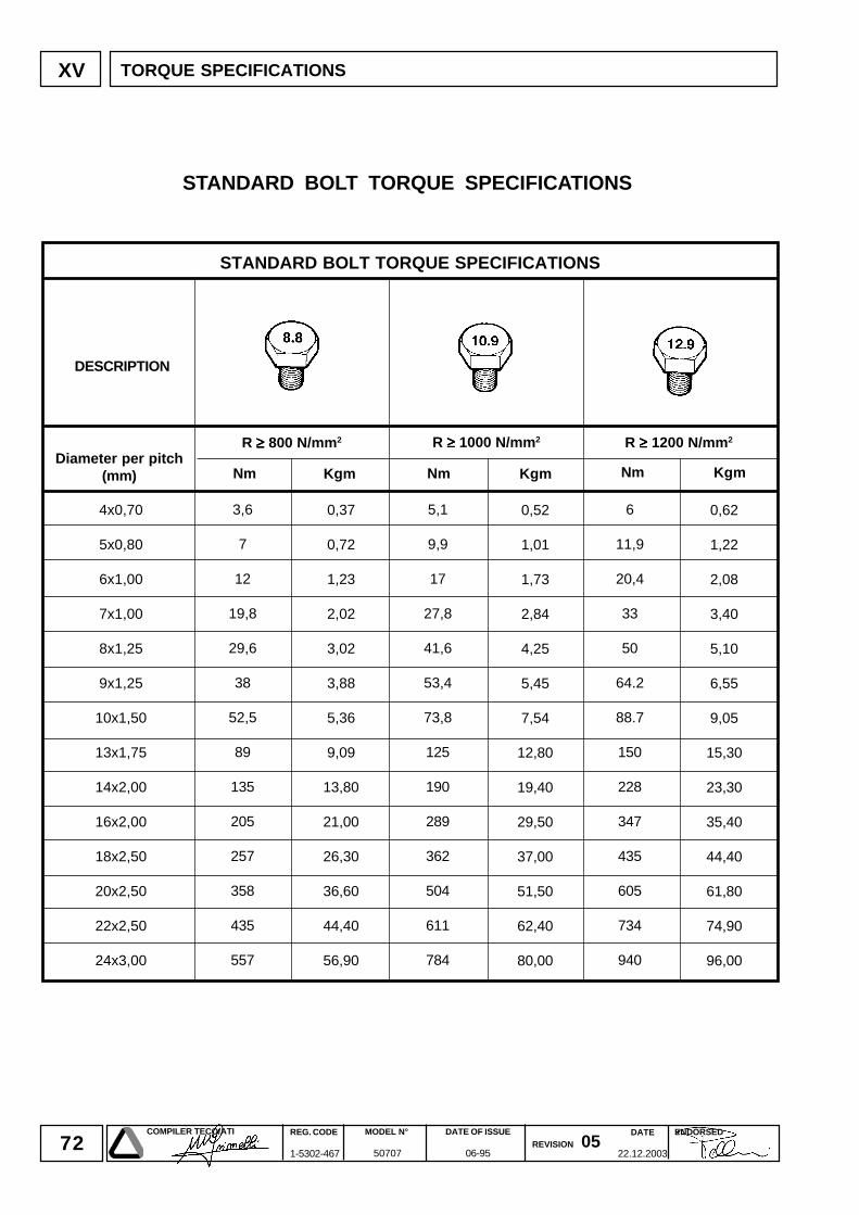
72DATE
22.12.2003
COMPILER TECO/ATI REG. CODE
1-5302-467
MODEL N°
50707
DATE OF ISSUE
06-95REVISION 05
ENDORSED
XV
R ≥≥≥≥≥ 800 N/mm2 R ≥≥≥≥≥ 1000 N/mm2 R ≥≥≥≥≥ 1200 N/mm2
4x0,70
5x0,80
6x1,00
7x1,00
8x1,25
9x1,25
10x1,50
13x1,75
14x2,00
16x2,00
18x2,50
20x2,50
22x2,50
24x3,00
0,62
1,22
2,08
3,40
5,10
6,55
9,05
15,30
23,30
35,40
44,40
61,80
74,90
96,00
0,52
1,01
1,73
2,84
4,25
5,45
7,54
12,80
19,40
29,50
37,00
51,50
62,40
80,00
3,6
7
12
19,8
29,6
38
52,5
89
135
205
257
358
435
557
5,1
9,9
17
27,8
41,6
53,4
73,8
125
190
289
362
504
611
784
6
11,9
20,4
33
50
64.2
88.7
150
228
347
435
605
734
940
0,37
0,72
1,23
2,02
3,02
3,88
5,36
9,09
13,80
21,00
26,30
36,60
44,40
56,90
Nm Kgm Nm Kgm Nm Kgm
STANDARD BOLT TORQUE SPECIFICATIONS
TORQUE SPECIFICATIONS
STANDARD BOLT TORQUE SPECIFICATIONS
DESCRIPTION
Diameter per pitch(mm)

73DATE
22.12.2003
COMPILER TECO/ATI REG. CODE
1-5302-467
MODEL N°
50707
DATE OF ISSUE
06-95REVISION 05
ENDORSED
La Lombardini si riserva il diritto di modificare in qualunque momento i dati contenuti in questa pubblicazione.Lombardini se rèserve le droit de modifier, à n'importe quel moment, les données reportées dans cettepublication.Data reported in this issue can be modified at any time by Lombardini.Lombardini vorbehält alle Rechte, diese Angabe jederzeit verändern.La Lombardini se reserva el derecho de modificar sin previo aviso los datos de esta publicación.
74
42100 Reggio Emilia – Italia - ITALYVia Cav. del Lavoro Adelmo Lombardini, 2 - Cas. Post. 1074Tel. (+39) 0522 3891 - Telex 530003 Motlom I – Telegr.: LombarmotorR.E.A. 227083 - Reg. Impr. RE 10875Cod. fiscale e Partita IVA 01829970357 - CEE Code IT 01829970357E-MAIL: [email protected]: http://www.lombardini.it
DATE
22.12.2003
COMPILER TECO/ATI REG. CODE
1-5302-467
MODEL N°
50707
DATE OF ISSUE
06-95REVISION 05
ENDORSED
Recommended