Manual
VIPA System SLIO Signal modules
SM
Order No.: VIPA HB300E_SM Rev. 09/38

L
Manual VIPA System SLIO Contents
Subject to change to cater for technical progress.
The information contained in this manual is supplied without warranties. The information is subject to change without notice. © Copyright 2009 VIPA, Gesellschaft für Visualisierung und Prozess-
automatisierung mbH Ohmstraße 4, D-91074 Herzogenaurach,
Tel.: +49 (91 32) 744 -0 Fax.: +49 (91 32) 744-1864 EMail: [email protected] http://www.vipa.de Hotline: +49 (91 32) 744-1150 All rights reserved
The contents of this manual were verified with respect to the hard- and software. However, we assume no responsibility for any discrepancies or errors. The information in this manual is verified on a regular basis and any required corrections will be included in subsequent editions. Suggestions for improvement are always welcome.
VIPA, SLIO and System 300V are registered trademarks of VIPA Gesellschaft für Visualisierung und Prozessautomatisierung mbH. SPEED7 is a registered trademark of profichip GmbH. SIMATIC, STEP and S7-300 are registered trademarks of Siemens AG. Any other trademarks referred to in the text are the trademarks of the respective owner and we acknowledge their registration.
Disclaimer of liability
Trademarks
About this manual Manual VIPA System SLIO
Subject to change to cater for technical progress.
About this manual
This manual describes the signal modules (SM) of the system SLIO from VIPA. Here you may find besides of a product overview a detailed description of the single modules. You’ll receive information about the connection and the deployment of the System SLIO SM modules.
Chapter 1: Basics and Assembly The focus of this chapter is on the introduction of the VIPA System SLIO. Here you will find the information required to assemble and wire a controller system consisting of System SLIO components. Besides the dimensions the general technical data of System SLIO will be found. Chapter 2: Digital input In this chapter you will find the description of the digital input modules of the System SLIO from VIPA. Chapter 3: Digital output The digital output modules of the System SLIO will be found here. Chapter 4: Analog input After the introduction to the analog input modules and the list of the measuring ranges the description of the analog input modules of the System SLIO will be found here. Chapter 5: Analog output After the introduction to the analog output and the list of the output ranges the description of the analog output modules of the System SLIO will be found here.
Overview
Manual VIPA System SLIO Contents
HB300E - SM - Rev. 09/38 i
Contents User considerations ................................................................................. 1 Safety information.................................................................................... 2 Chapter 1 Basics and Assembly ..................................................... 1-1
Safety Information for Users................................................................. 1-2 System conception ............................................................................... 1-3 Dimensions .......................................................................................... 1-6 Installation............................................................................................ 1-7 Wiring................................................................................................. 1-11 Installation guidelines ......................................................................... 1-14 General data ...................................................................................... 1-17
Chapter 2 Digital Input ..................................................................... 2-1 VIPA 021-1BB00 - DI 2xDC 24V .......................................................... 2-2 VIPA 021-1BD00 - DI 4xDC 24V .......................................................... 2-4 VIPA 021-1BD40 - DI 4xDC 24V 3 wire................................................ 2-6 VIPA 021-1BF00 - DI 8xDC 24V........................................................... 2-8
Chapter 3 Digital Output .................................................................. 3-1 VIPA 022-1BB00 - DO 2xDC 24V 0.5A ................................................ 3-2 VIPA 022-1BD00 - DO 4xDC 24V 0.5A ................................................ 3-4 VIPA 022-1BF00 - DO 8xDC 24V 0.5A ................................................ 3-6
Chapter 4 Analog Input .................................................................... 4-1 General ................................................................................................ 4-2 Analog value ........................................................................................ 4-3 Measuring ranges ................................................................................ 4-4 VIPA 031-1BB30 - AI 2x12Bit 0...10V................................................... 4-8 VIPA 031-1BB40 - AI 2x12Bit 0(4)...20mA ......................................... 4-12 VIPA 031-1BD30 - AI 4x12Bit 0...10V ................................................ 4-17 VIPA 031-1BD40 - AI 4x12Bit 0(4)...20mA ......................................... 4-21 VIPA 031-1BD80 - AI 4x16Bit R/RTD................................................. 4-26
Chapter 5 Analog Output ................................................................. 5-1 General ................................................................................................ 5-2 Analog value ........................................................................................ 5-3 Output ranges ...................................................................................... 5-4 VIPA 032-1BB30 - AO 2x12Bit 0...10V................................................. 5-5 VIPA 032-1BB40 - AO 2x12Bit 0(4)...20mA.......................................... 5-9 VIPA 032-1BD30 - AO 4x12Bit 0...10V............................................... 5-14 VIPA 032-1BD40 - AO 4x12Bit 0(4)...20mA ....................................... 5-19
Contents Manual VIPA System SLIO
ii HB300E - SM - Rev. 09/38
Manual VIPA System SLIO User considerations
HB300E - SM - Rev. 09/38 1
User considerations
This manual describes the signal modules of the System SLIO from VIPA. It contains a description of the structure, project engineering and deployment.
The manual is targeted at users who have a background in automation technology.
The manual consists of chapters. Every chapter provides a self-contained description of a specific topic.
The following guides are available in the manual: • an overall table of contents at the beginning of the manual • an overview of the topics for every chapter
The manual is available in: • printed form, on paper • in electronic form as PDF-file (Adobe Acrobat Reader)
Important passages in the text are highlighted by following icons and headings:
Danger! Immediate or likely danger. Personal injury is possible.
Attention! Damages to property is likely if these warnings are not heeded.
Note! Supplementary information and useful tips.
Objective and contents
Target audience
Structure of the manual
Guide to the document
Availability
Icons Headings
Safty information Manual VIPA System SLIO
2 HB300E - SM - Rev. 09/38
Safety information
The System SLIO is constructed and produced for: • communication and process control • general control and automation applications • industrial applications • operation within the environmental conditions specified in the technical
data • installation into a cubicle
Danger! This device is not certified for applications in • in explosive environments (EX-zone)
The manual must be available to all personnel in the • project design department • installation department • commissioning • operation
The following conditions must be met before using or commissioning the components described in this manual: • Modification to the process control system should only be carried out
when the system has been disconnected from power! • Installation and modifications only by properly trained personnel • The national rules and regulations of the respective country must be
satisfied (installation, safety, EMC ...)
National rules and regulations apply to the disposal of the unit!
Applications conforming with specifications
Documentation
Disposal
Manual VIPA System SLIO Chapter 1 Basics and Assembly
HB300E - SM - Rev. 09/38 1-1
Chapter 1 Basics and Assembly
The focus of this chapter is on the introduction of the VIPA System SLIO. Here you will find the information required to assemble and wire a controller system consisting of System SLIO components. Besides the dimensions the general technical data of System SLIO will be found.
Topic Page Chapter 1 Basics and Assembly ..................................................... 1-1
Safety Information for Users................................................................. 1-2 System conception ............................................................................... 1-3 Dimensions .......................................................................................... 1-6 Installation............................................................................................ 1-7 Wiring................................................................................................. 1-11 Installation guidelines ......................................................................... 1-14 General data ...................................................................................... 1-17
Overview
Content
Chapter 1 Basics and Assembly Manual VIPA System SLIO
1-2 HB300E - SM - Rev. 09/38
Safety Information for Users
VIPA modules make use of highly integrated components in MOS-Technology. These components are extremely sensitive to over-voltages that can occur during electrostatic discharges. The following symbol is attached to modules that can be destroyed by electrostatic discharges.
The Symbol is located on the module, the module rack or on packing material and it indicates the presence of electrostatic sensitive equipment. It is possible that electrostatic sensitive equipment is destroyed by energies and voltages that are far less than the human threshold of perception. These voltages can occur where persons do not discharge themselves before handling electrostatic sensitive modules and they can damage components thereby, causing the module to become inoperable or unusable. Modules that have been damaged by electrostatic discharges can fail after a temperature change, mechanical shock or changes in the electrical load. Only the consequent implementation of protection devices and meticulous attention to the applicable rules and regulations for handling the respective equipment can prevent failures of electrostatic sensitive modules.
Modules must be shipped in the original packing material.
When you are conducting measurements on electrostatic sensitive modules you should take the following precautions: • Floating instruments must be discharged before use. • Instruments must be grounded. Modifying electrostatic sensitive modules you should only use soldering irons with grounded tips.
Attention! Personnel and instruments should be grounded when working on electrostatic sensitive modules.
Handling of electrostatic sensitive modules
Shipping of modules
Measurements and alterations on electrostatic sensitive modules
Manual VIPA System SLIO Chapter 1 Basics and Assembly
HB300E - SM - Rev. 09/38 1-3
System conception
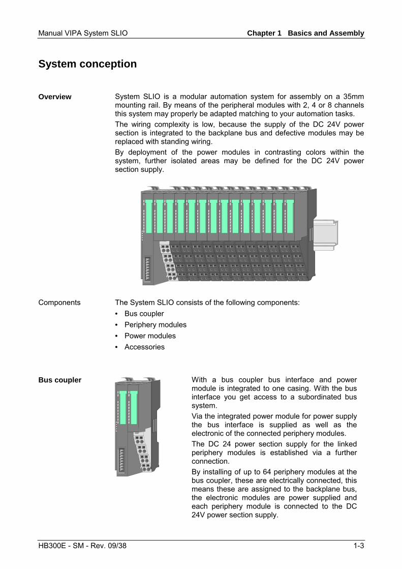
System SLIO is a modular automation system for assembly on a 35mm mounting rail. By means of the peripheral modules with 2, 4 or 8 channels this system may properly be adapted matching to your automation tasks. The wiring complexity is low, because the supply of the DC 24V power section is integrated to the backplane bus and defective modules may be replaced with standing wiring. By deployment of the power modules in contrasting colors within the system, further isolated areas may be defined for the DC 24V power section supply.
The System SLIO consists of the following components: • Bus coupler • Periphery modules • Power modules • Accessories
With a bus coupler bus interface and power module is integrated to one casing. With the bus interface you get access to a subordinated bus system. Via the integrated power module for power supply the bus interface is supplied as well as the electronic of the connected periphery modules. The DC 24 power section supply for the linked periphery modules is established via a further connection. By installing of up to 64 periphery modules at the bus coupler, these are electrically connected, this means these are assigned to the backplane bus, the electronic modules are power supplied and each periphery module is connected to the DC 24V power section supply.
Overview
Components
Bus coupler
Chapter 1 Basics and Assembly Manual VIPA System SLIO
1-4 HB300E - SM - Rev. 09/38
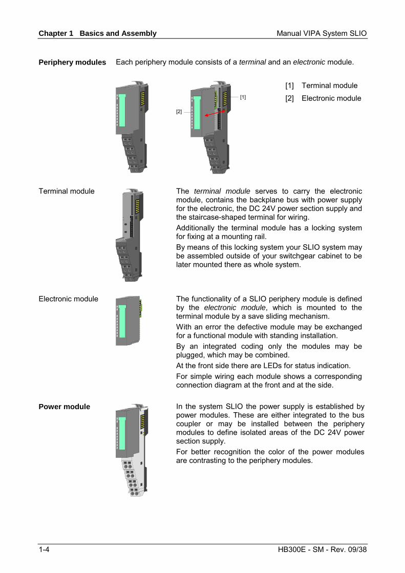
Each periphery module consists of a terminal and an electronic module.
[1]
[2]
[1]
[2]
Terminal module
Electronic module
The terminal module serves to carry the electronic module, contains the backplane bus with power supply for the electronic, the DC 24V power section supply and the staircase-shaped terminal for wiring. Additionally the terminal module has a locking system for fixing at a mounting rail. By means of this locking system your SLIO system may be assembled outside of your switchgear cabinet to be later mounted there as whole system.
The functionality of a SLIO periphery module is defined by the electronic module, which is mounted to the terminal module by a save sliding mechanism. With an error the defective module may be exchanged for a functional module with standing installation. By an integrated coding only the modules may be plugged, which may be combined. At the front side there are LEDs for status indication. For simple wiring each module shows a corresponding connection diagram at the front and at the side.
In the system SLIO the power supply is established by power modules. These are either integrated to the bus coupler or may be installed between the periphery modules to define isolated areas of the DC 24V power section supply. For better recognition the color of the power modules are contrasting to the periphery modules.
Periphery modules
Terminal module
Electronic module
Power module
Manual VIPA System SLIO Chapter 1 Basics and Assembly
HB300E - SM - Rev. 09/38 1-5
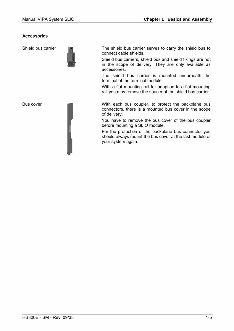
The shield bus carrier serves to carry the shield bus to connect cable shields. Shield bus carriers, shield bus and shield fixings are not in the scope of delivery. They are only available as accessories. The shield bus carrier is mounted underneath the terminal of the terminal module. With a flat mounting rail for adaption to a flat mounting rail you may remove the spacer of the shield bus carrier.
With each bus coupler, to protect the backplane bus connectors, there is a mounted bus cover in the scope of delivery. You have to remove the bus cover of the bus coupler before mounting a SLIO module. For the protection of the backplane bus connector you should always mount the bus cover at the last module of your system again.
Accessories
Shield bus carrier
Bus cover
Chapter 1 Basics and Assembly Manual VIPA System SLIO
1-6 HB300E - SM - Rev. 09/38
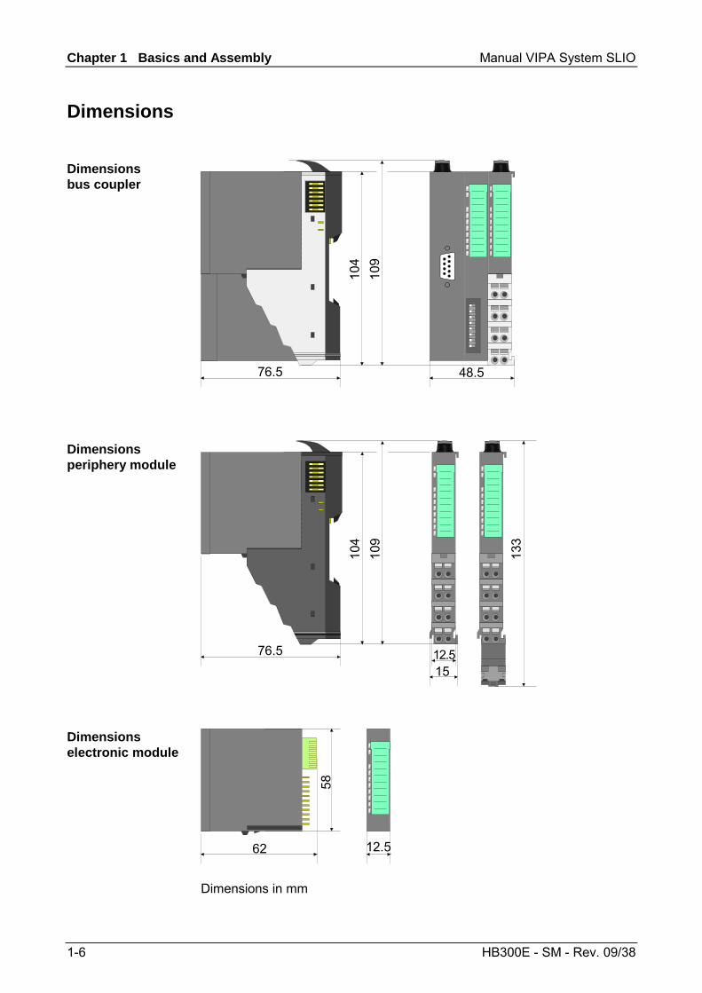
Dimensions
104
109
76.5 48.5
104
109
76.515
133
12.5
58
62 12.5
Dimensions in mm
Dimensions bus coupler
Dimensions periphery module
Dimensions electronic module
Manual VIPA System SLIO Chapter 1 Basics and Assembly
HB300E - SM - Rev. 09/38 1-7
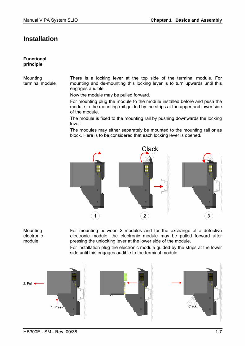
Installation
There is a locking lever at the top side of the terminal module. For mounting and de-mounting this locking lever is to turn upwards until this engages audible. Now the module may be pulled forward. For mounting plug the module to the module installed before and push the module to the mounting rail guided by the strips at the upper and lower side of the module. The module is fixed to the mounting rail by pushing downwards the locking lever. The modules may either separately be mounted to the mounting rail or as block. Here is to be considered that each locking lever is opened.
Clack
1 2 3 For mounting between 2 modules and for the exchange of a defective electronic module, the electronic module may be pulled forward after pressing the unlocking lever at the lower side of the module. For installation plug the electronic module guided by the strips at the lower side until this engages audible to the terminal module.
1. Press
2. Pull
Clack
Functional principle
Mounting terminal module
Mounting electronic module
Chapter 1 Basics and Assembly Manual VIPA System SLIO
1-8 HB300E - SM - Rev. 09/38
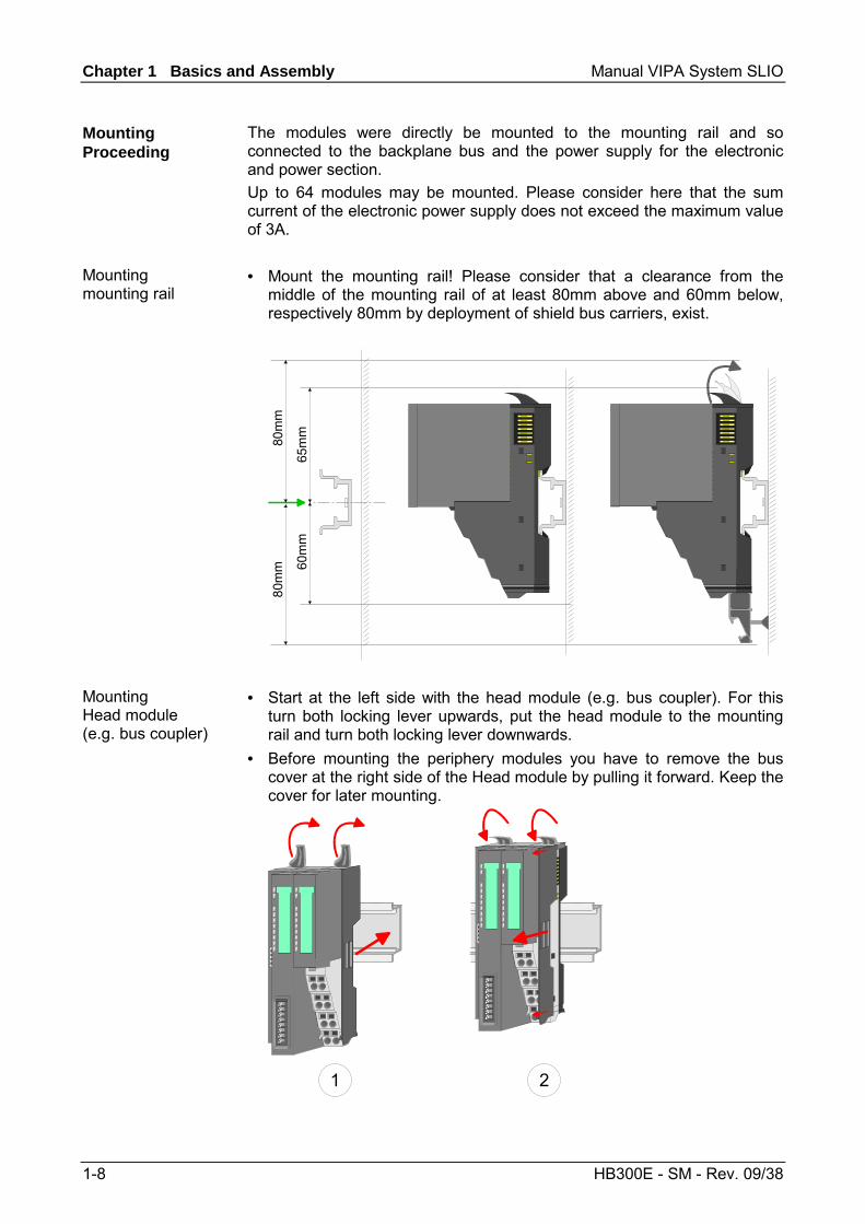
The modules were directly be mounted to the mounting rail and so connected to the backplane bus and the power supply for the electronic and power section. Up to 64 modules may be mounted. Please consider here that the sum current of the electronic power supply does not exceed the maximum value of 3A. • Mount the mounting rail! Please consider that a clearance from the
middle of the mounting rail of at least 80mm above and 60mm below, respectively 80mm by deployment of shield bus carriers, exist.
80m
m80
mm 60
mm
65m
m
• Start at the left side with the head module (e.g. bus coupler). For this
turn both locking lever upwards, put the head module to the mounting rail and turn both locking lever downwards.
• Before mounting the periphery modules you have to remove the bus cover at the right side of the Head module by pulling it forward. Keep the cover for later mounting.
1 2
Mounting Proceeding
Mounting mounting rail
Mounting Head module (e.g. bus coupler)
Manual VIPA System SLIO Chapter 1 Basics and Assembly
HB300E - SM - Rev. 09/38 1-9
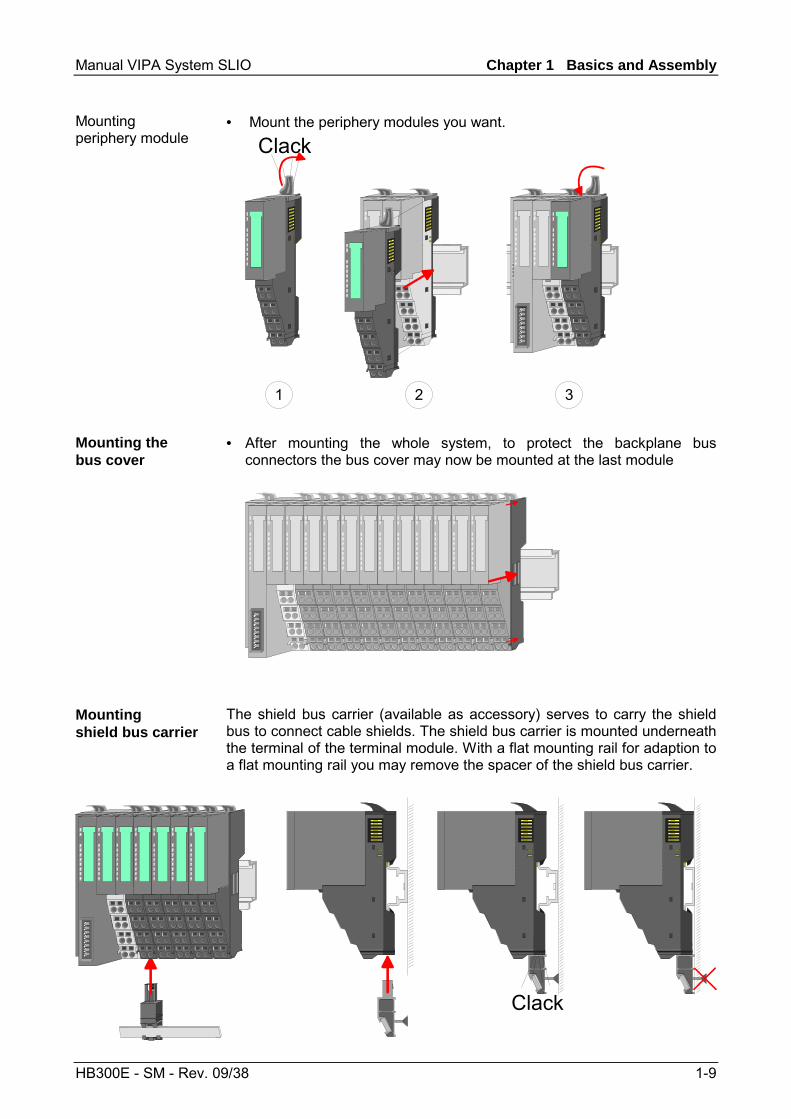
• Mount the periphery modules you want.
1 2
Clack
3 • After mounting the whole system, to protect the backplane bus
connectors the bus cover may now be mounted at the last module
The shield bus carrier (available as accessory) serves to carry the shield bus to connect cable shields. The shield bus carrier is mounted underneath the terminal of the terminal module. With a flat mounting rail for adaption to a flat mounting rail you may remove the spacer of the shield bus carrier.
Clack
Mounting periphery module
Mounting the bus cover
Mounting shield bus carrier
Chapter 1 Basics and Assembly Manual VIPA System SLIO
1-10 HB300E - SM - Rev. 09/38
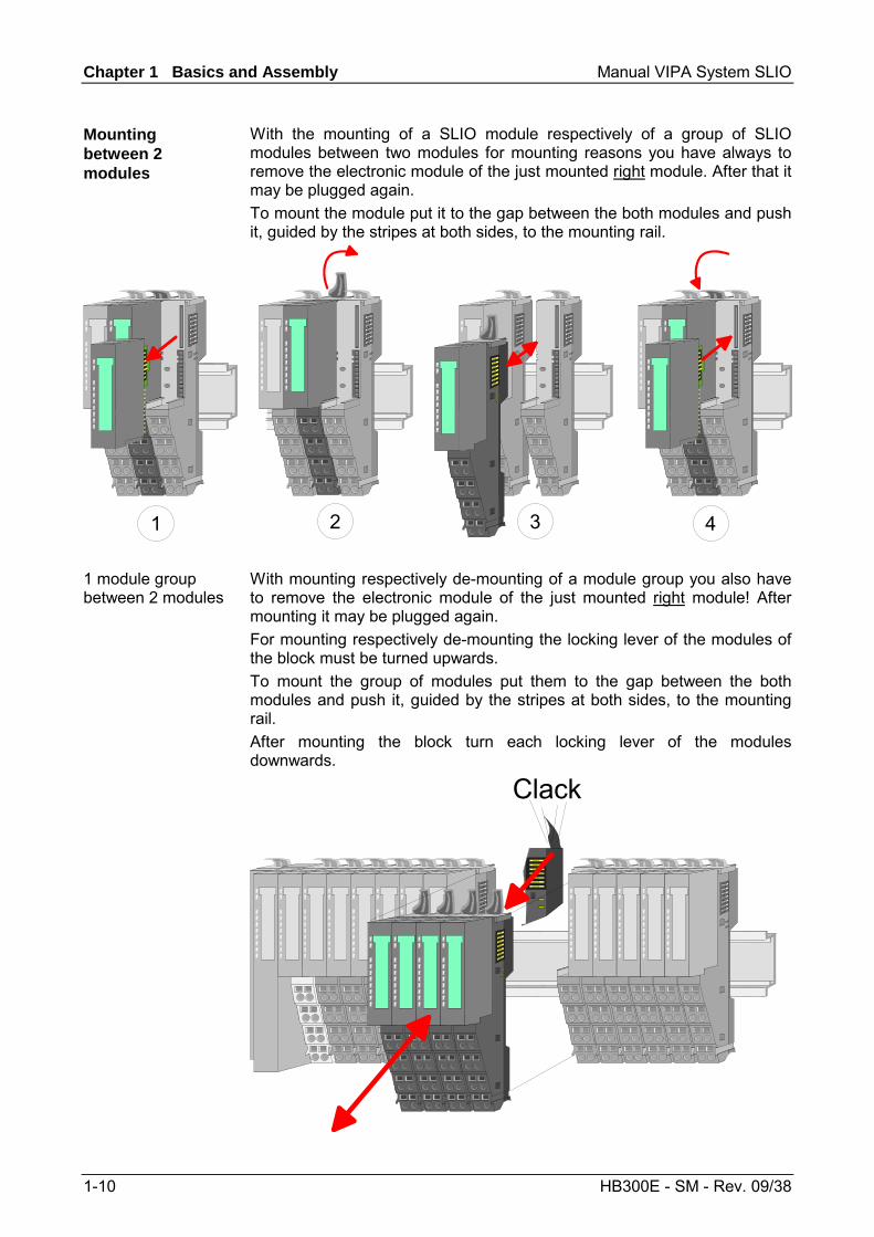
With the mounting of a SLIO module respectively of a group of SLIO modules between two modules for mounting reasons you have always to remove the electronic module of the just mounted right module. After that it may be plugged again. To mount the module put it to the gap between the both modules and push it, guided by the stripes at both sides, to the mounting rail.
1 2 3 4
With mounting respectively de-mounting of a module group you also have to remove the electronic module of the just mounted right module! After mounting it may be plugged again. For mounting respectively de-mounting the locking lever of the modules of the block must be turned upwards. To mount the group of modules put them to the gap between the both modules and push it, guided by the stripes at both sides, to the mounting rail. After mounting the block turn each locking lever of the modules downwards.
Clack
Mounting between 2 modules
1 module group between 2 modules
Manual VIPA System SLIO Chapter 1 Basics and Assembly
HB300E - SM - Rev. 09/38 1-11
Wiring
DC24V0V
DC24V0V
1
2
DC24V max. 10A
SysDC5V max. 3A
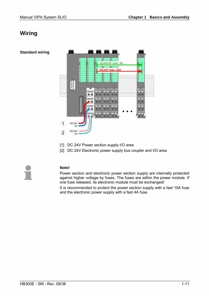
[1] DC 24V Power section supply I/O area [2] DC 24V Electronic power supply bus coupler and I/O area
Note! Power section and electronic power section supply are internally protected against higher voltage by fuses. The fuses are within the power module. If one fuse released, its electronic module must be exchanged! It is recommended to protect the power section supply with a fast 10A fuse and the electronic power supply with a fast 4A fuse.
Standard wiring
Chapter 1 Basics and Assembly Manual VIPA System SLIO
1-12 HB300E - SM - Rev. 09/38
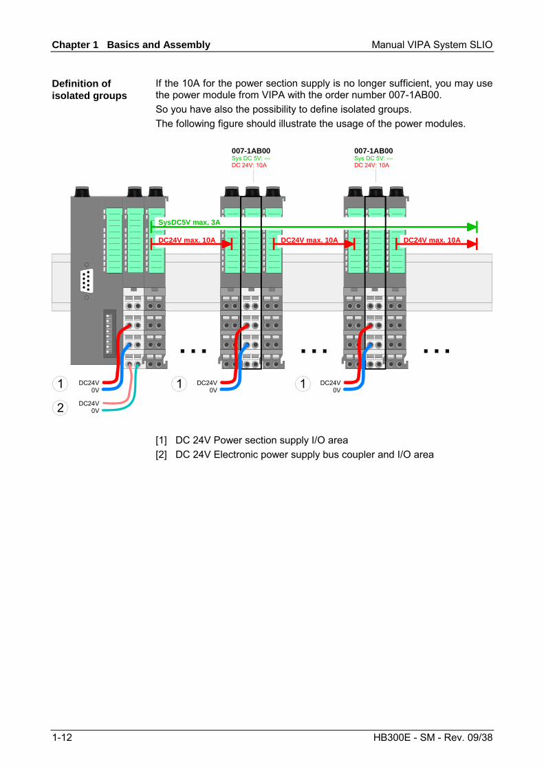
If the 10A for the power section supply is no longer sufficient, you may use the power module from VIPA with the order number 007-1AB00. So you have also the possibility to define isolated groups. The following figure should illustrate the usage of the power modules.
007-1AB00Sys DC 5V: ---DC 24V: 10A
007-1AB00Sys DC 5V: ---DC 24V: 10A
DC24V0V
DC24V0V
DC24V max. 10A
SysDC5V max. 3A
DC24V max. 10A DC24V max. 10A
DC24V0V
DC24V0V
1
2
1 1
[1] DC 24V Power section supply I/O area [2] DC 24V Electronic power supply bus coupler and I/O area
Definition of isolated groups
Manual VIPA System SLIO Chapter 1 Basics and Assembly
HB300E - SM - Rev. 09/38 1-13
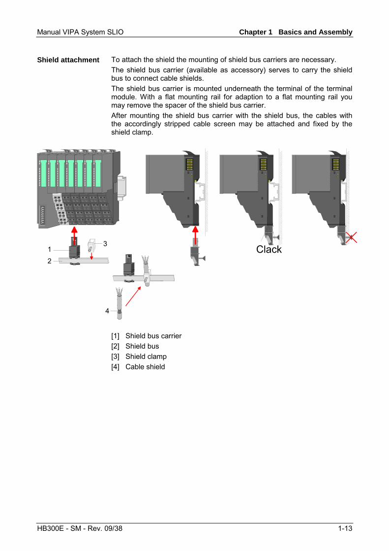
To attach the shield the mounting of shield bus carriers are necessary. The shield bus carrier (available as accessory) serves to carry the shield bus to connect cable shields. The shield bus carrier is mounted underneath the terminal of the terminal module. With a flat mounting rail for adaption to a flat mounting rail you may remove the spacer of the shield bus carrier. After mounting the shield bus carrier with the shield bus, the cables with the accordingly stripped cable screen may be attached and fixed by the shield clamp.
Clack1
2
3
4
[1] Shield bus carrier [2] Shield bus [3] Shield clamp [4] Cable shield
Shield attachment
Chapter 1 Basics and Assembly Manual VIPA System SLIO
1-14 HB300E - SM - Rev. 09/38
Installation guidelines
The installation guidelines contain information about the interference free deployment of System SLIO. There is the description of the ways, interference may occur in your control, how you can make sure the electromagnetic digestibility (EMC), and how you manage the isolation.
Electromagnetic digestibility (EMC) means the ability of an electrical device, to function error free in an electromagnetic environment without being interferenced res. without interferencing the environment. All System SLIO components are developed for the deployment in hard industrial environments and fulfill high demands on the EMC. Nevertheless you should project an EMC planning before installing the components and take conceivable interference causes into account.
Electromagnetic interferences may interfere your control via different ways: • Fields • I/O signal conductors • Bus system • Current supply • Protected earth conductor Depending on the spreading medium (lead bound or lead free) and the distance to the interference cause, interferences to your control occur by means of different coupling mechanisms. One differs: • galvanic coupling • capacitive coupling • inductive coupling • radiant coupling
General
What means EMC?
Possible interference causes
Manual VIPA System SLIO Chapter 1 Basics and Assembly
HB300E - SM - Rev. 09/38 1-15
In the most times it is enough to take care of some elementary rules to guarantee the EMC. Please regard the following basic rules when installing your PLC. • Take care of a correct area-wide grounding of the inactive metal parts
when installing your components. - Install a central connection between the ground and the protected
earth conductor system. - Connect all inactive metal extensive and impedance-low. - Please try not to use aluminum parts. Aluminum is easily oxidizing
and is therefore less suitable for grounding. • When cabling, take care of the correct line routing.
- Organize your cabling in line groups (high voltage, current supply, signal and data lines).
- Always lay your high voltage lines and signal res. data lines in separate channels or bundles.
- Route the signal and data lines as near as possible beside ground areas (e.g. suspension bars, metal rails, tin cabinet).
• Proof the correct fixing of the lead isolation. - Data lines must be laid isolated. - Analog lines must be laid isolated. When transmitting signals with
small amplitudes the one sided laying of the isolation may be favorable.
- Lay the line isolation extensively on an isolation/protected earth con-ductor rail directly after the cabinet entry and fix the isolation with cable clamps.
- Make sure that the isolation/protected earth conductor rail is connected impedance-low with the cabinet.
- Use metallic or metalized plug cases for isolated data lines. • In special use cases you should appoint special EMC actions.
- Wire all inductivities with erase links, which are not addressed by the System SLIO modules.
- For lightening cabinets you should prefer incandescent lamps and avoid luminescent lamps.
• Create a homogeneous reference potential and ground all electrical operating supplies when possible. - Please take care for the targeted employment of the grounding
actions. The grounding of the PLC is a protection and functionality activity.
- Connect installation parts and cabinets with the System SLIO in star topology with the isolation/protected earth conductor system. So you avoid ground loops.
- If potential differences between installation parts and cabinets occur, lay sufficiently dimensioned potential compensation lines.
Basic rules for EMC
Chapter 1 Basics and Assembly Manual VIPA System SLIO
1-16 HB300E - SM - Rev. 09/38
Electrical, magnetically and electromagnetic interference fields are weakened by means of an isolation, one talks of absorption. Via the isolation rail, that is connected conductive with the rack, interference currents are shunt via cable isolation to the ground. Hereby you have to make sure, that the connection to the protected earth conduc-tor is impedance-low, because otherwise the interference currents may appear as interference cause. When isolating cables you have to regard the following: • If possible, use only cables with isolation tangle. • The hiding power of the isolation should be higher than 80%. • Normally you should always lay the isolation of cables on both sides.
Only by means of the both-sided connection of the isolation you achieve high quality interference suppression in the higher frequency area. Only as exception you may also lay the isolation one-sided. Then you only achieve the absorption of the lower frequencies. A one-sided isolation connection may be convenient, if: - the conduction of a potential compensating line is not possible - analog signals (some mV res. µA) are transferred - foil isolations (static isolations) are used.
• With data lines always use metallic or metalized plugs for serial couplings. Fix the isolation of the data line at the plug rack. Do not lay the isolation on the PIN 1 of the plug bar!
• At stationary operation it is convenient to strip the insulated cable interruption free and lay it on the isolation/protected earth conductor line.
• To fix the isolation tangles use cable clamps out of metal. The clamps must clasp the isolation extensively and have well contact.
• Lay the isolation on an isolation rail directly after the entry of the cable in the cabinet. Lead the isolation further on to the System SLIO module and don't lay it on there again!
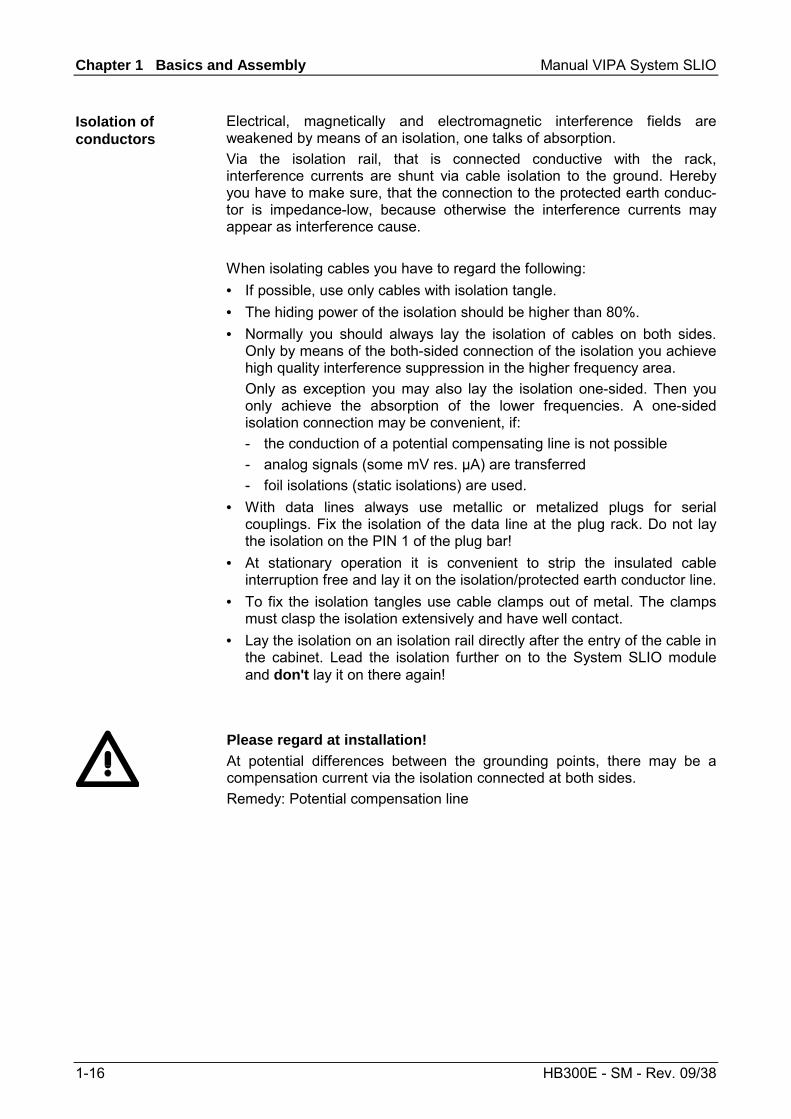
Please regard at installation! At potential differences between the grounding points, there may be a compensation current via the isolation connected at both sides. Remedy: Potential compensation line
Isolation of conductors
Manual VIPA System SLIO Chapter 1 Basics and Assembly
HB300E - SM - Rev. 09/38 1-17
General data
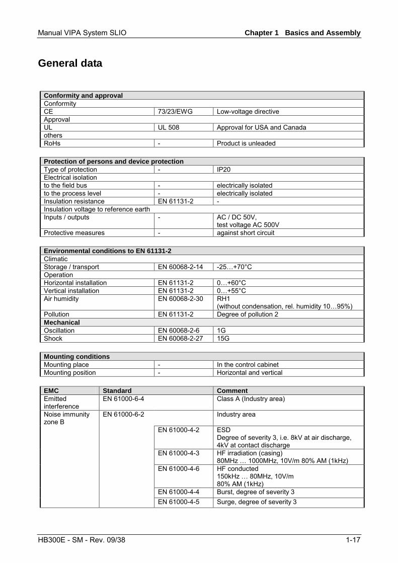
Conformity and approval Conformity CE 73/23/EWG Low-voltage directive Approval UL UL 508 Approval for USA and Canada others RoHs - Product is unleaded
Protection of persons and device protection Type of protection - IP20 Electrical isolation to the field bus - electrically isolated to the process level - electrically isolated Insulation resistance EN 61131-2 - Insulation voltage to reference earth Inputs / outputs - AC / DC 50V,
test voltage AC 500V Protective measures - against short circuit
Environmental conditions to EN 61131-2 Climatic Storage / transport EN 60068-2-14 -25…+70°C Operation Horizontal installation EN 61131-2 0…+60°C Vertical installation EN 61131-2 0…+55°C Air humidity EN 60068-2-30 RH1
(without condensation, rel. humidity 10…95%) Pollution EN 61131-2 Degree of pollution 2 Mechanical Oscillation EN 60068-2-6 1G Shock EN 60068-2-27 15G
Mounting conditions Mounting place - In the control cabinet Mounting position - Horizontal and vertical
EMC Standard Comment Emitted interference
EN 61000-6-4 Class A (Industry area)
Industry area
EN 61000-4-2 ESD Degree of severity 3, i.e. 8kV at air discharge, 4kV at contact discharge
EN 61000-4-3 HF irradiation (casing) 80MHz … 1000MHz, 10V/m 80% AM (1kHz)
EN 61000-4-6 HF conducted 150kHz … 80MHz, 10V/m 80% AM (1kHz)
EN 61000-4-4 Burst, degree of severity 3
Noise immunity zone B
EN 61000-6-2
EN 61000-4-5 Surge, degree of severity 3
Chapter 1 Basics and Assembly Manual VIPA System SLIO
1-18 HB300E - SM - Rev. 09/38
Manual VIPA System SLIO Chapter 2 Digital Input
HB300E - SM - Rev. 09/38 2-1
Chapter 2 Digital Input
In this chapter you will find the description of the digital input modules of the System SLIO from VIPA.
Topic Page Chapter 2 Digital Input ..................................................................... 2-1
VIPA 021-1BB00 - DI 2xDC 24V .......................................................... 2-2 VIPA 021-1BD00 - DI 4xDC 24V .......................................................... 2-4 VIPA 021-1BD40 - DI 4xDC 24V 3 wire................................................ 2-6 VIPA 021-1BF00 - DI 8xDC 24V........................................................... 2-8
Overview
Content
Chapter 2 Digital Input Manual VIPA System SLIO
2-2 HB300E - SM - Rev. 09/38
VIPA 021-1BB00 - DI 2xDC 24V
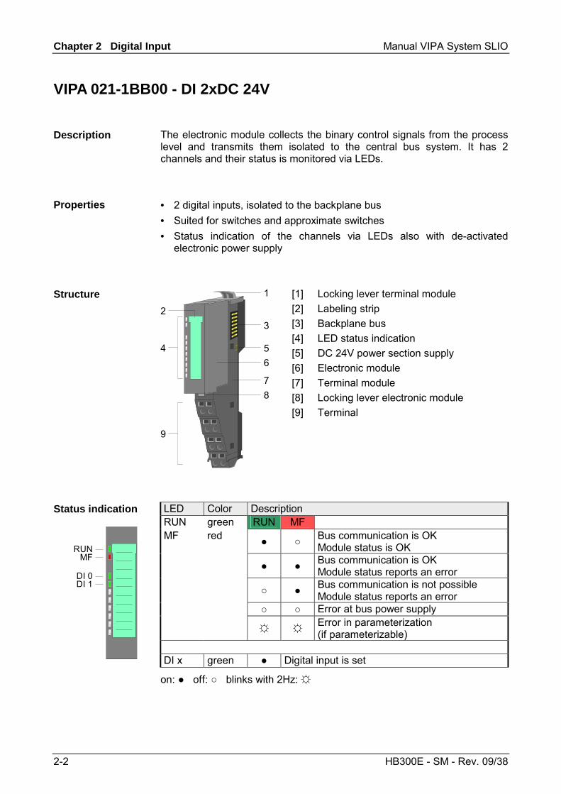
The electronic module collects the binary control signals from the process level and transmits them isolated to the central bus system. It has 2 channels and their status is monitored via LEDs.
• 2 digital inputs, isolated to the backplane bus • Suited for switches and approximate switches • Status indication of the channels via LEDs also with de-activated
electronic power supply
1
3
546
78
9
2
[1] [2] [3] [4] [5] [6] [7] [8] [9]
Locking lever terminal module Labeling strip Backplane bus LED status indication DC 24V power section supply Electronic module Terminal module Locking lever electronic module Terminal
LED Color Description RUN green RUN MF MF red Bus communication is OK
Module status is OK Bus communication is OK
Module status reports an error Bus communication is not possible
Module status reports an error Error at bus power supply Error in parameterization
(if parameterizable)
Status indication
RUNMF
DI 0DI 1
DI x green Digital input is set
on: off: blinks with 2Hz:
Description
Properties
Structure
Manual VIPA System SLIO Chapter 2 Digital Input
HB300E - SM - Rev. 09/38 2-3
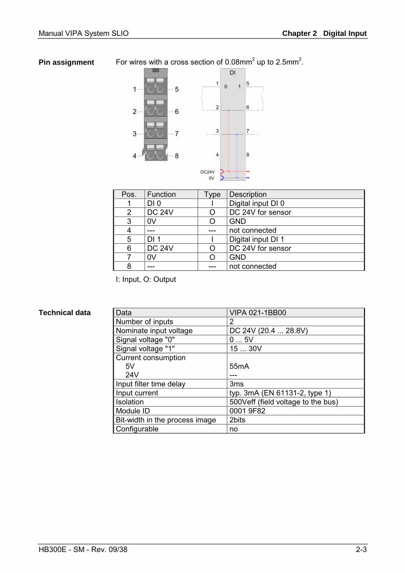
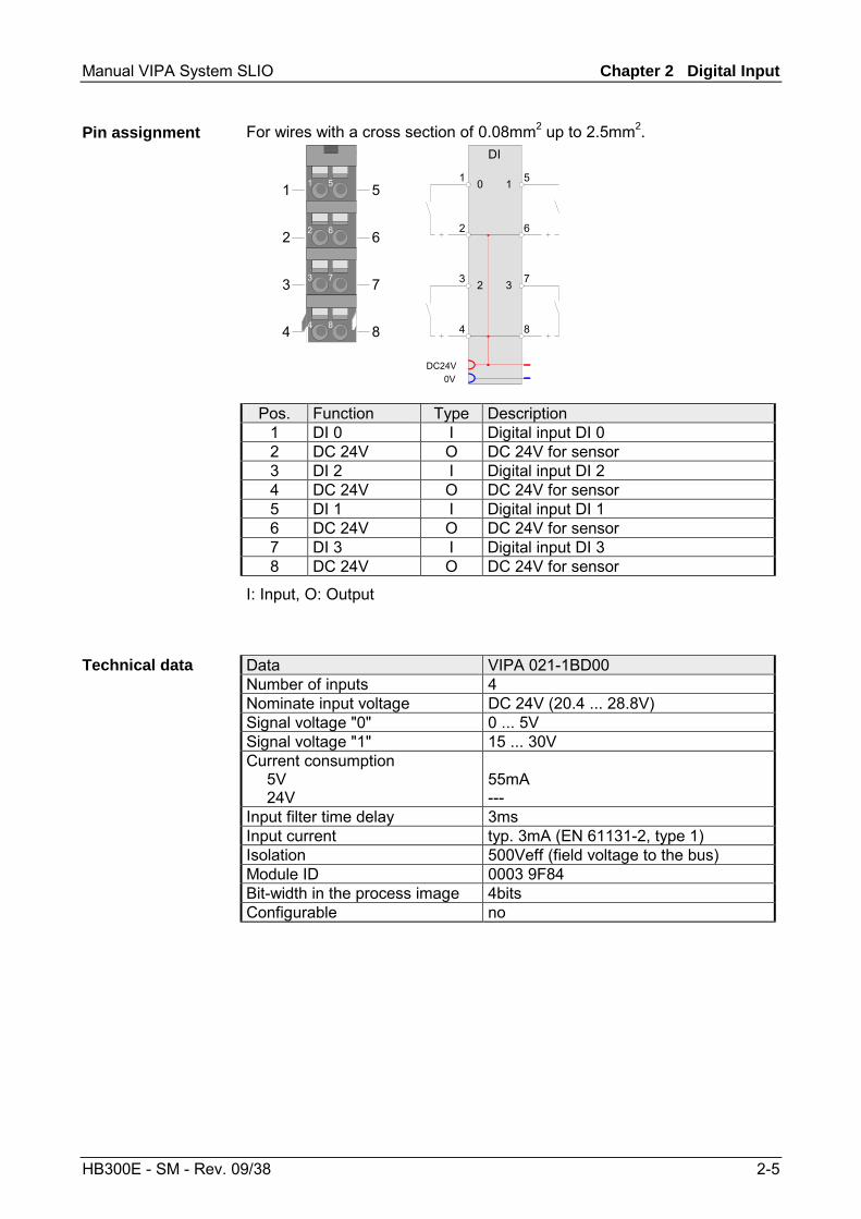
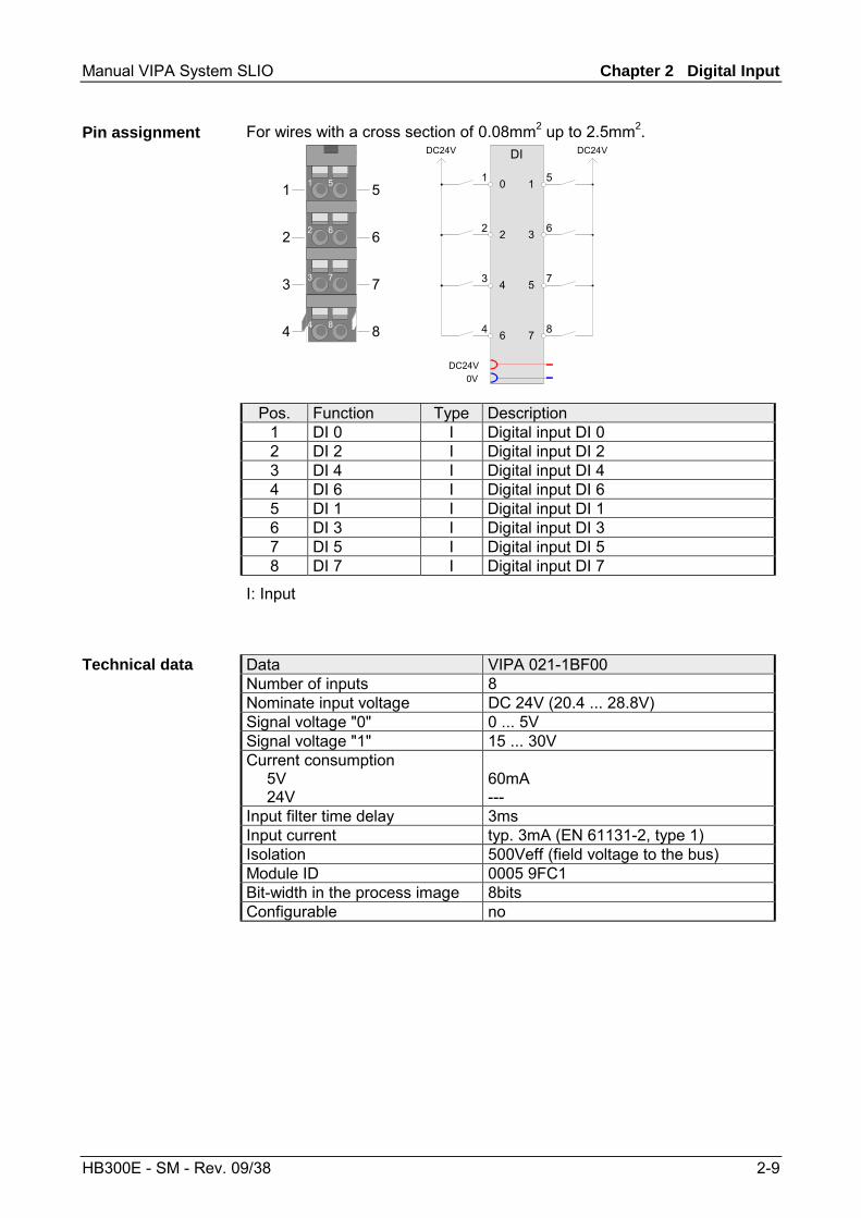
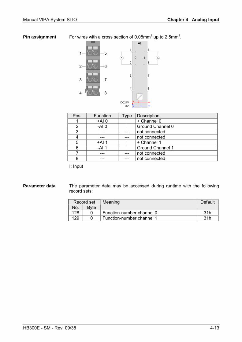
For wires with a cross section of 0.08mm2 up to 2.5mm2.
2 6
3 7
4 8
1 51
2
3
4
5
6
7
8
2 6
3 7
4 8
1 5
DI
DC24V0V
0 1
Pos. Function Type Description 1 DI 0 I Digital input DI 0 2 DC 24V O DC 24V for sensor 3 0V O GND 4 --- --- not connected 5 DI 1 I Digital input DI 1 6 DC 24V O DC 24V for sensor 7 0V O GND 8 --- --- not connected
I: Input, O: Output
Data VIPA 021-1BB00 Number of inputs 2 Nominate input voltage DC 24V (20.4 ... 28.8V) Signal voltage "0" 0 ... 5V Signal voltage "1" 15 ... 30V Current consumption 5V 24V
55mA ---
Input filter time delay 3ms Input current typ. 3mA (EN 61131-2, type 1) Isolation 500Veff (field voltage to the bus) Module ID 0001 9F82 Bit-width in the process image 2bits Configurable no
Pin assignment
Technical data

Chapter 2 Digital Input Manual VIPA System SLIO
2-4 HB300E - SM - Rev. 09/38
VIPA 021-1BD00 - DI 4xDC 24V
The electronic module collects the binary control signals from the process level and transmits them isolated to the central bus system. It has 4 channels and their status is monitored via LEDs.
• 4 digital inputs, isolated to the backplane bus • Suited for switches and approximate switches • Status indication of the channels via LEDs also with de-activated
electronic power supply
1
3
546
78
9
2
[1] [2] [3] [4] [5] [6] [7] [8] [9]
Locking lever terminal module Labeling strip Backplane bus LED status indication DC 24V power section supply Electronic module Terminal module Locking lever electronic module Terminal
LED Color Description RUN green RUN MF MF red Bus communication is OK
Module status is OK Bus communication is OK
Module status reports an error Bus communication is not possible
Module status reports an error Error at bus power supply Error in parameterization
(if parameterizable)
Status indication
RUNMF
DI 0DI 1DI 2DI 3
DI x green Digital input is set
on: off: blinks with 2Hz:
Description
Properties
Structure
Manual VIPA System SLIO Chapter 2 Digital Input
HB300E - SM - Rev. 09/38 2-5
For wires with a cross section of 0.08mm2 up to 2.5mm2.
2 6
3 7
4 8
1 51
2
3
4
5
6
7
8
2 6
3 7
4 8
1 5
DI
DC24V0V
0 1
2 3
Pos. Function Type Description 1 DI 0 I Digital input DI 0 2 DC 24V O DC 24V for sensor 3 DI 2 I Digital input DI 2 4 DC 24V O DC 24V for sensor 5 DI 1 I Digital input DI 1 6 DC 24V O DC 24V for sensor 7 DI 3 I Digital input DI 3 8 DC 24V O DC 24V for sensor
I: Input, O: Output
Data VIPA 021-1BD00 Number of inputs 4 Nominate input voltage DC 24V (20.4 ... 28.8V) Signal voltage "0" 0 ... 5V Signal voltage "1" 15 ... 30V Current consumption 5V 24V
55mA ---
Input filter time delay 3ms Input current typ. 3mA (EN 61131-2, type 1) Isolation 500Veff (field voltage to the bus) Module ID 0003 9F84 Bit-width in the process image 4bits Configurable no
Pin assignment
Technical data
Chapter 2 Digital Input Manual VIPA System SLIO
2-6 HB300E - SM - Rev. 09/38
VIPA 021-1BD40 - DI 4xDC 24V 3 wire
The electronic module collects the binary control signals from the process level and transmits them isolated to the central bus system. It has 4 channels and their status is monitored via LEDs.
• 4 digital inputs with 3 wire connection, isolated to the backplane bus • Suited for switches and approximate switches • Status indication of the channels via LEDs also with de-activated
electronic power supply
1
3
546
78
9
2
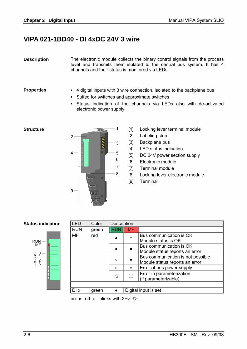
[1] [2] [3] [4] [5] [6] [7] [8] [9]
Locking lever terminal module Labeling strip Backplane bus LED status indication DC 24V power section supply Electronic module Terminal module Locking lever electronic module Terminal
LED Color Description RUN green RUN MF MF red Bus communication is OK
Module status is OK Bus communication is OK
Module status reports an error Bus communication is not possible
Module status reports an error Error at bus power supply Error in parameterization
(if parameterizable)
Status indication
RUNMF
DI 0DI 1DI 2DI 3
DI x green Digital input is set
on: off: blinks with 2Hz:
Description
Properties
Structure
Manual VIPA System SLIO Chapter 2 Digital Input
HB300E - SM - Rev. 09/38 2-7
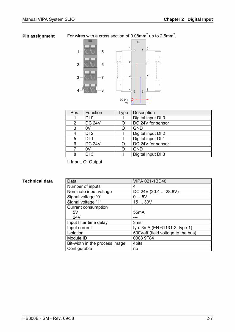
For wires with a cross section of 0.08mm2 up to 2.5mm2.
2 6
3 7
4 8
1 51
2
3
4
5
6
7
8
2 6
3 7
4 8
1 5
DI
DC24V0V
0 1
2 3
Pos. Function Type Description 1 DI 0 I Digital input DI 0 2 DC 24V O DC 24V for sensor 3 0V O GND 4 DI 2 I Digital input DI 2 5 DI 1 I Digital input DI 1 6 DC 24V O DC 24V for sensor 7 0V O GND 8 DI 3 I Digital input DI 3
I: Input, O: Output
Data VIPA 021-1BD40 Number of inputs 4 Nominate input voltage DC 24V (20.4 ... 28.8V) Signal voltage "0" 0 ... 5V Signal voltage "1" 15 ... 30V Current consumption 5V 24V
55mA ---
Input filter time delay 3ms Input current typ. 3mA (EN 61131-2, type 1) Isolation 500Veff (field voltage to the bus) Module ID 0008 9F84 Bit-width in the process image 4bits Configurable no
Pin assignment
Technical data
Chapter 2 Digital Input Manual VIPA System SLIO
2-8 HB300E - SM - Rev. 09/38
VIPA 021-1BF00 - DI 8xDC 24V
The electronic module collects the binary control signals from the process level and transmits them isolated to the central bus system. It has 8 channels and their status is monitored via LEDs.
• 8 digital inputs, isolated to the backplane bus • Suited for switches and approximate switches • Status indication of the channels via LEDs also with de-activated
electronic power supply
1
3
546
78
9
2
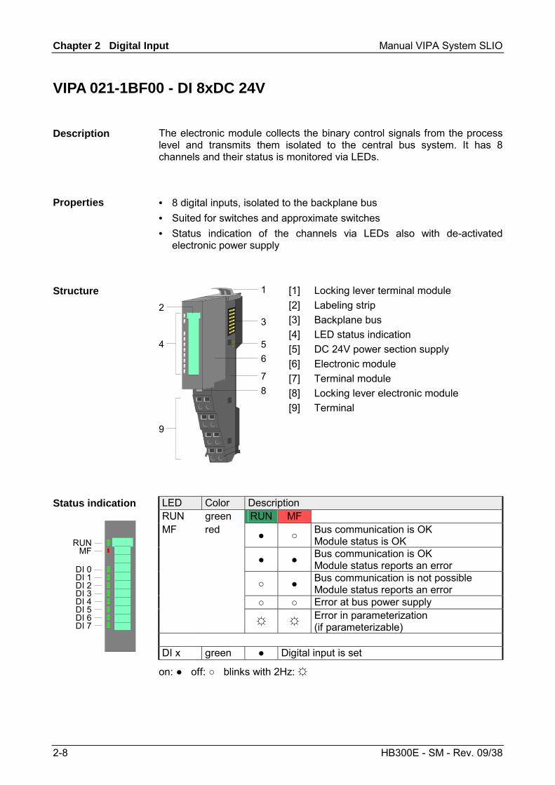
[1] [2] [3] [4] [5] [6] [7] [8] [9]
Locking lever terminal module Labeling strip Backplane bus LED status indication DC 24V power section supply Electronic module Terminal module Locking lever electronic module Terminal
LED Color Description RUN green RUN MF MF red Bus communication is OK
Module status is OK Bus communication is OK
Module status reports an error Bus communication is not possible
Module status reports an error Error at bus power supply Error in parameterization
(if parameterizable)
Status indication
RUNMF
DI 0DI 1DI 2DI 3DI 4DI 5DI 6DI 7
DI x green Digital input is set
on: off: blinks with 2Hz:
Description
Properties
Structure
Manual VIPA System SLIO Chapter 2 Digital Input
HB300E - SM - Rev. 09/38 2-9
For wires with a cross section of 0.08mm2 up to 2.5mm2.
2 6
3 7
4 8
1 51
2
3
4
5
6
7
8
2 6
3 7
4 8
1 5
DI
DC24V0V
DC24V DC24V
0
2
4
6 7
5
3
1
Pos. Function Type Description 1 DI 0 I Digital input DI 0 2 DI 2 I Digital input DI 2 3 DI 4 I Digital input DI 4 4 DI 6 I Digital input DI 6 5 DI 1 I Digital input DI 1 6 DI 3 I Digital input DI 3 7 DI 5 I Digital input DI 5 8 DI 7 I Digital input DI 7
I: Input
Data VIPA 021-1BF00 Number of inputs 8 Nominate input voltage DC 24V (20.4 ... 28.8V) Signal voltage "0" 0 ... 5V Signal voltage "1" 15 ... 30V Current consumption 5V 24V
60mA ---
Input filter time delay 3ms Input current typ. 3mA (EN 61131-2, type 1) Isolation 500Veff (field voltage to the bus) Module ID 0005 9FC1 Bit-width in the process image 8bits Configurable no
Pin assignment
Technical data
Chapter 2 Digital Input Manual VIPA System SLIO
2-10 HB300E - SM - Rev. 09/38
Manual VIPA System SLIO Chapter 3 Digital Output
HB300E - SM - Rev. 09/38 3-1
Chapter 3 Digital Output
The digital output modules of the System SLIO will be found here.
Topic Page Chapter 3 Digital Output .................................................................. 3-1
VIPA 022-1BB00 - DO 2xDC 24V 0.5A ................................................ 3-2 VIPA 022-1BD00 - DO 4xDC 24V 0.5A ................................................ 3-4 VIPA 022-1BF00 - DO 8xDC 24V 0.5A ................................................ 3-6
Overview
Content
Chapter 3 Digital Output Manual VIPA System SLIO
3-2 HB300E - SM - Rev. 09/38
VIPA 022-1BB00 - DO 2xDC 24V 0.5A
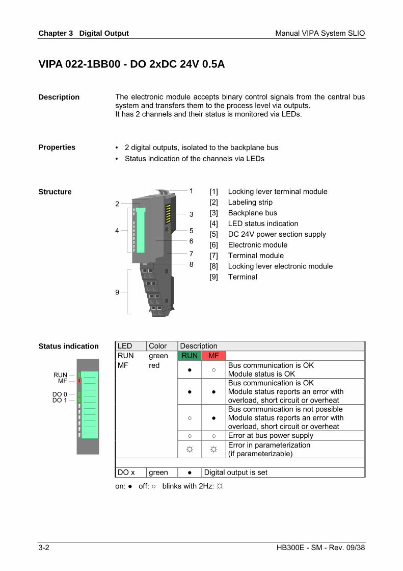
The electronic module accepts binary control signals from the central bus system and transfers them to the process level via outputs. It has 2 channels and their status is monitored via LEDs.
• 2 digital outputs, isolated to the backplane bus • Status indication of the channels via LEDs
1
3
546
78
9
2
[1] [2] [3] [4] [5] [6] [7] [8] [9]
Locking lever terminal module Labeling strip Backplane bus LED status indication DC 24V power section supply Electronic module Terminal module Locking lever electronic module Terminal
LED Color Description RUN green RUN MF MF red Bus communication is OK
Module status is OK
Bus communication is OK Module status reports an error with overload, short circuit or overheat
Bus communication is not possible Module status reports an error with overload, short circuit or overheat
Error at bus power supply Error in parameterization
(if parameterizable)
Status indication
RUNMF
DO 0DO 1
DO x green Digital output is set
on: off: blinks with 2Hz:
Description
Properties
Structure
Manual VIPA System SLIO Chapter 3 Digital Output
HB300E - SM - Rev. 09/38 3-3
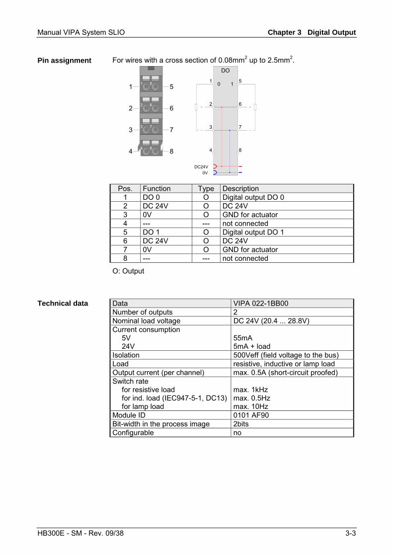
For wires with a cross section of 0.08mm2 up to 2.5mm2.
2 6
3 7
4 8
1 51
2
3
4
5
6
7
8
2 6
3 7
4 8
1 5
DO
DC24V0V
0 1
Pos. Function Type Description 1 DO 0 O Digital output DO 0 2 DC 24V O DC 24V 3 0V O GND for actuator 4 --- --- not connected 5 DO 1 O Digital output DO 1 6 DC 24V O DC 24V 7 0V O GND for actuator 8 --- --- not connected
O: Output
Data VIPA 022-1BB00 Number of outputs 2 Nominal load voltage DC 24V (20.4 ... 28.8V) Current consumption 5V 24V
55mA 5mA + load
Isolation 500Veff (field voltage to the bus) Load resistive, inductive or lamp load Output current (per channel) max. 0.5A (short-circuit proofed) Switch rate for resistive load for ind. load (IEC947-5-1, DC13) for lamp load
max. 1kHz max. 0.5Hz max. 10Hz
Module ID 0101 AF90 Bit-width in the process image 2bits Configurable no
Pin assignment
Technical data

Chapter 3 Digital Output Manual VIPA System SLIO
3-4 HB300E - SM - Rev. 09/38
VIPA 022-1BD00 - DO 4xDC 24V 0.5A
The electronic module accepts binary control signals from the central bus system and transfers them to the process level via outputs. It has 4 channels and their status is monitored via LEDs.
• 4 digital outputs, isolated to the backplane bus • Status indication of the channels via LEDs
1
3
546
78
9
2
[1] [2] [3] [4] [5] [6] [7] [8] [9]
Locking lever terminal module Labeling strip Backplane bus LED status indication DC 24V power section supply Electronic module Terminal module Locking lever electronic module Terminal
LED Color Description RUN green RUN MF MF red Bus communication is OK
Module status is OK
Bus communication is OK Module status reports an error with overload, short circuit or overheat
Bus communication is not possible Module status reports an error with overload, short circuit or overheat
Error at bus power supply Error in parameterization
(if parameterizable)
Status indication
RUNMF
DO 0DO 1DO 2DO 3
DO x green Digital output is set
on: off: blinks with 2Hz:
Description
Properties
Structure
Manual VIPA System SLIO Chapter 3 Digital Output
HB300E - SM - Rev. 09/38 3-5
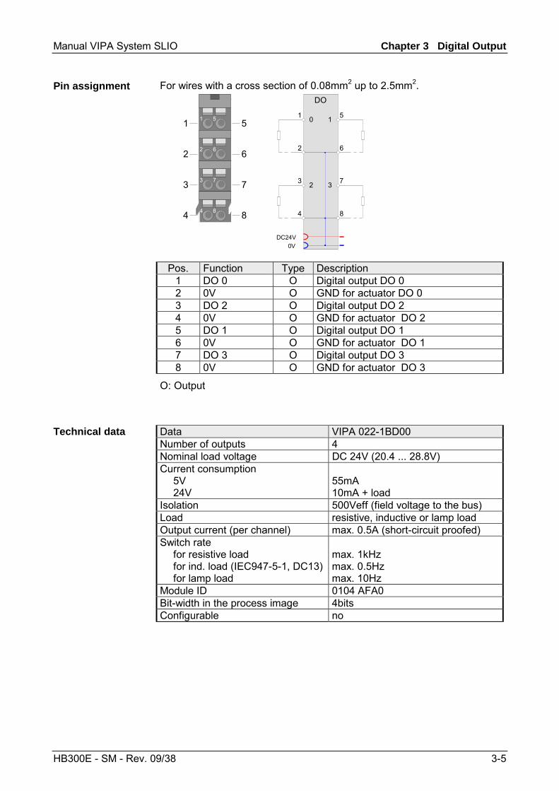
For wires with a cross section of 0.08mm2 up to 2.5mm2.
2 6
3 7
4 8
1 51
2
3
4
5
6
7
8
2 6
3 7
4 8
1 5
DO
DC24V0V
0 1
2 3
Pos. Function Type Description 1 DO 0 O Digital output DO 0 2 0V O GND for actuator DO 0 3 DO 2 O Digital output DO 2 4 0V O GND for actuator DO 2 5 DO 1 O Digital output DO 1 6 0V O GND for actuator DO 1 7 DO 3 O Digital output DO 3 8 0V O GND for actuator DO 3
O: Output
Data VIPA 022-1BD00 Number of outputs 4 Nominal load voltage DC 24V (20.4 ... 28.8V) Current consumption 5V 24V
55mA 10mA + load
Isolation 500Veff (field voltage to the bus) Load resistive, inductive or lamp load Output current (per channel) max. 0.5A (short-circuit proofed) Switch rate for resistive load for ind. load (IEC947-5-1, DC13) for lamp load
max. 1kHz max. 0.5Hz max. 10Hz
Module ID 0104 AFA0 Bit-width in the process image 4bits Configurable no
Pin assignment
Technical data
Chapter 3 Digital Output Manual VIPA System SLIO
3-6 HB300E - SM - Rev. 09/38
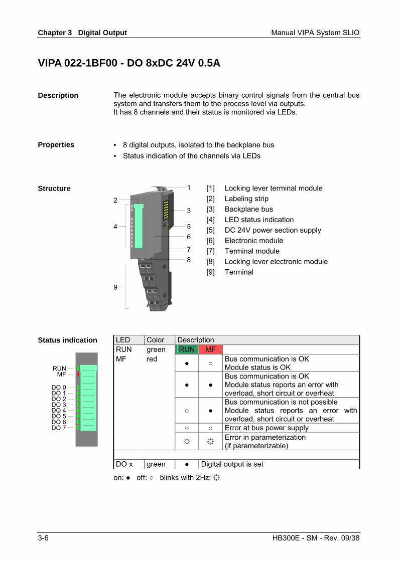
VIPA 022-1BF00 - DO 8xDC 24V 0.5A
The electronic module accepts binary control signals from the central bus system and transfers them to the process level via outputs. It has 8 channels and their status is monitored via LEDs.
• 8 digital outputs, isolated to the backplane bus • Status indication of the channels via LEDs
1
3
546
78
9
2
[1] [2] [3] [4] [5] [6] [7] [8] [9]
Locking lever terminal module Labeling strip Backplane bus LED status indication DC 24V power section supply Electronic module Terminal module Locking lever electronic module Terminal
LED Color Description RUN green RUN MF MF red Bus communication is OK
Module status is OK
Bus communication is OK Module status reports an error with overload, short circuit or overheat
Bus communication is not possible Module status reports an error with overload, short circuit or overheat
Error at bus power supply Error in parameterization
(if parameterizable)
Status indication
RUNMF
DO 0DO 1DO 2DO 3DO 4DO 5DO 6DO 7
DO x green Digital output is set
on: off: blinks with 2Hz:
Description
Properties
Structure
Manual VIPA System SLIO Chapter 3 Digital Output
HB300E - SM - Rev. 09/38 3-7
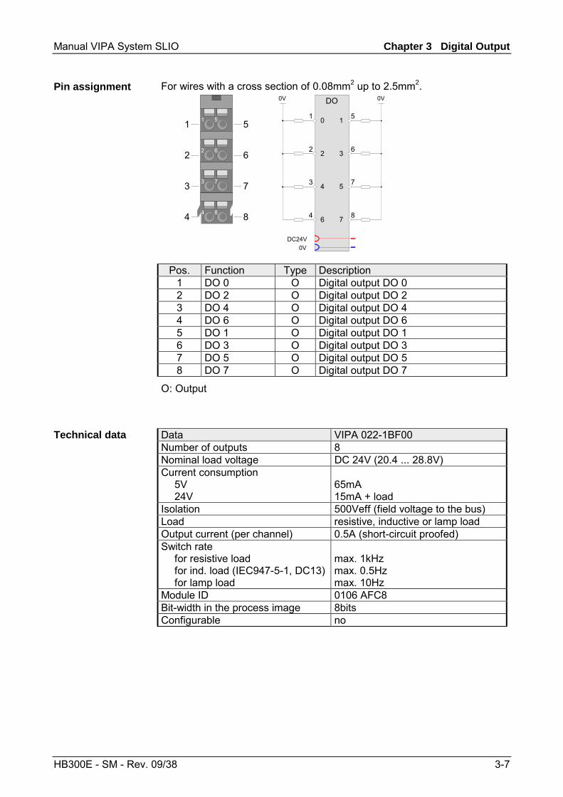
For wires with a cross section of 0.08mm2 up to 2.5mm2.
2 6
3 7
4 8
1 51
2
3
4
5
6
7
8
2 6
3 7
4 8
1 5
DO
DC24V0V
0V 0V
0
2
4
6 7
5
3
1
Pos. Function Type Description 1 DO 0 O Digital output DO 0 2 DO 2 O Digital output DO 2 3 DO 4 O Digital output DO 4 4 DO 6 O Digital output DO 6 5 DO 1 O Digital output DO 1 6 DO 3 O Digital output DO 3 7 DO 5 O Digital output DO 5 8 DO 7 O Digital output DO 7
O: Output
Data VIPA 022-1BF00 Number of outputs 8 Nominal load voltage DC 24V (20.4 ... 28.8V) Current consumption 5V 24V
65mA 15mA + load
Isolation 500Veff (field voltage to the bus) Load resistive, inductive or lamp load Output current (per channel) 0.5A (short-circuit proofed) Switch rate for resistive load for ind. load (IEC947-5-1, DC13) for lamp load
max. 1kHz max. 0.5Hz max. 10Hz
Module ID 0106 AFC8 Bit-width in the process image 8bits Configurable no
Pin assignment
Technical data
Chapter 3 Digital Output Manual VIPA System SLIO
3-8 HB300E - SM - Rev. 09/38
Manual VIPA System SLIO Chapter 4 Analog Input
HB300E - SM - Rev. 09/38 4-1
Chapter 4 Analog Input
After the introduction to the analog input modules and the list of the measuring ranges the description of the analog input modules of the System SLIO will be found here.
Topic Page Chapter 4 Analog Input .................................................................... 4-1
General ................................................................................................ 4-2 Analog value ........................................................................................ 4-3 Measuring ranges................................................................................. 4-4 VIPA 031-1BB30 - AI 2x12Bit 0...10V................................................... 4-8 VIPA 031-1BB40 - AI 2x12Bit 0(4)...20mA.......................................... 4-12 VIPA 031-1BD30 - AI 4x12Bit 0...10V................................................. 4-17 VIPA 031-1BD40 - AI 4x12Bit 0(4)...20mA ......................................... 4-21 VIPA 031-1BD80 - AI 4x16Bit R/RTD................................................. 4-26
Overview
Content
Chapter 4 Analog Input Manual VIPA System SLIO
4-2 HB300E - SM - Rev. 09/38
General
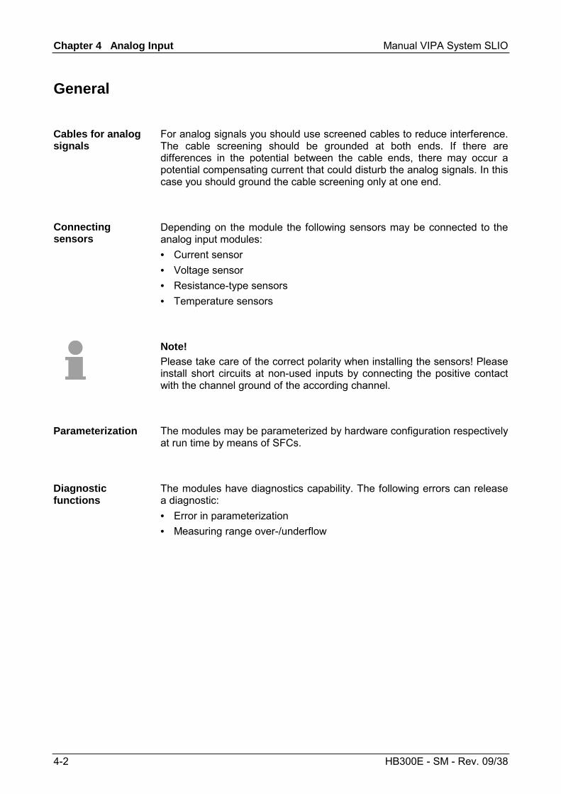
For analog signals you should use screened cables to reduce interference. The cable screening should be grounded at both ends. If there are differences in the potential between the cable ends, there may occur a potential compensating current that could disturb the analog signals. In this case you should ground the cable screening only at one end.
Depending on the module the following sensors may be connected to the analog input modules: • Current sensor • Voltage sensor • Resistance-type sensors • Temperature sensors
Note! Please take care of the correct polarity when installing the sensors! Please install short circuits at non-used inputs by connecting the positive contact with the channel ground of the according channel.
The modules may be parameterized by hardware configuration respectively at run time by means of SFCs.
The modules have diagnostics capability. The following errors can release a diagnostic: • Error in parameterization • Measuring range over-/underflow
Cables for analog signals
Connecting sensors
Parameterization
Diagnostic functions
Manual VIPA System SLIO Chapter 4 Analog Input
HB300E - SM - Rev. 09/38 4-3
Analog value
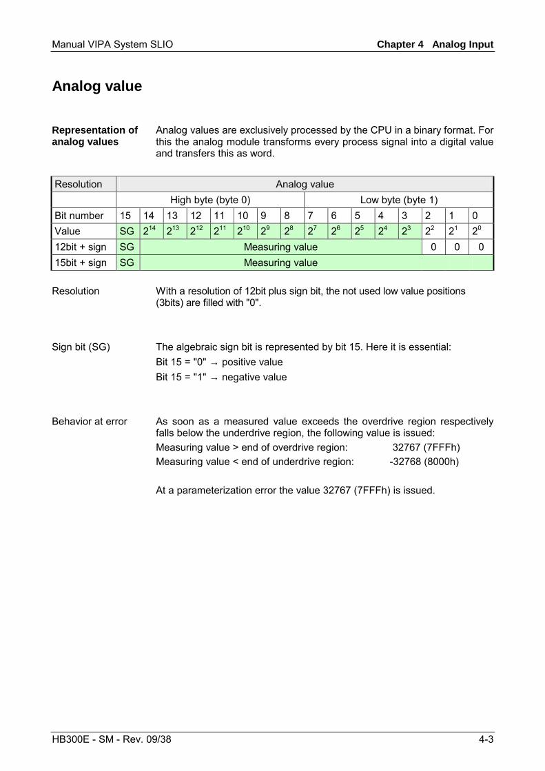
Analog values are exclusively processed by the CPU in a binary format. For this the analog module transforms every process signal into a digital value and transfers this as word.
Resolution Analog value High byte (byte 0) Low byte (byte 1) Bit number 15 14 13 12 11 10 9 8 7 6 5 4 3 2 1 0 Value SG 214 213 212 211 210 29 28 27 26 25 24 23 22 21 20 12bit + sign SG Measuring value 0 0 0 15bit + sign SG Measuring value
With a resolution of 12bit plus sign bit, the not used low value positions (3bits) are filled with "0".
The algebraic sign bit is represented by bit 15. Here it is essential: Bit 15 = "0" → positive value Bit 15 = "1" → negative value
As soon as a measured value exceeds the overdrive region respectively falls below the underdrive region, the following value is issued: Measuring value > end of overdrive region: 32767 (7FFFh) Measuring value < end of underdrive region: -32768 (8000h) At a parameterization error the value 32767 (7FFFh) is issued.
Representation of analog values
Resolution
Sign bit (SG)
Behavior at error
Chapter 4 Analog Input Manual VIPA System SLIO
4-4 HB300E - SM - Rev. 09/38
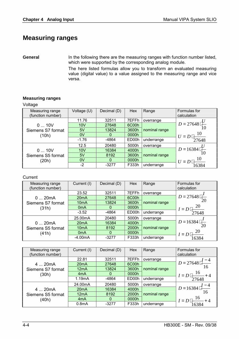
Measuring ranges
In the following there are the measuring ranges with function number listed, which were supported by the corresponding analog module. The here listed formulas allow you to transform an evaluated measuring value (digital value) to a value assigned to the measuring range and vice versa.
Measuring range (function number)
Voltage (U) Decimal (D) Hex Range Formulas for calculation
11.76 32511 7EFFh overrange 10V 27648 6C00h 5V 13824 3600h 0V 0 0000h
nominal range 0 ... 10V
Siemens S7 format (10h)
-1.76 -4864 ED00h underrange
1027648 UD ⋅=
2764810⋅= DU
12.5 20480 5000h overrange 10V 16384 4000h 5V 8192 3600h 0V 0 0000h
nominal range 0 ... 10V
Siemens S5 format (20h)
-2 -3277 F333h underrange
1016384 UD ⋅=
1638410⋅= DU
Measuring range (function number)
Current (I) Decimal (D) Hex Range Formulas for calculation
23.52 32511 7EFFh overrange 20mA 27648 6C00h 10mA 13824 3600h 0mA 0 0000h
nominal range 0 ... 20mA
Siemens S7 format (31h)
-3.52 -4864 ED00h underrange
2027648 ID ⋅=
2764820⋅= DI
25.00mA 20480 5000h overrange 20mA 16384 4000h 10mA 8192 2000h 0mA 0 0000h
nominal range 0 ... 20mA
Siemens S5 format (41h)
-4.00mA -3277 F333h underrange
2016384 ID ⋅=
1638420⋅= DI
Measuring range (function number)
Current (I) Decimal (D) Hex Range Formulas for calculation
22.81 32511 7EFFh overrange 20mA 27648 6C00h 12mA 13824 3600h 4mA 0 0000h
nominal range 4 ... 20mA
Siemens S7 format (30h)
1.19mA -4864 ED00h underrange
16427648 −⋅= ID
427648
16 +⋅= DI
24.00mA 20480 5000h overrange 20mA 16384 4000h 12mA 8192 2000h 4mA 0 0000h
nominal range 4 ... 20mA
Siemens S5 format (40h)
0.8mA -3277 F333h underrange
16416384 −⋅= ID
416384
16 +⋅= DI
General
Measuring ranges Voltage
Current
Manual VIPA System SLIO Chapter 4 Analog Input
HB300E - SM - Rev. 09/38 4-5
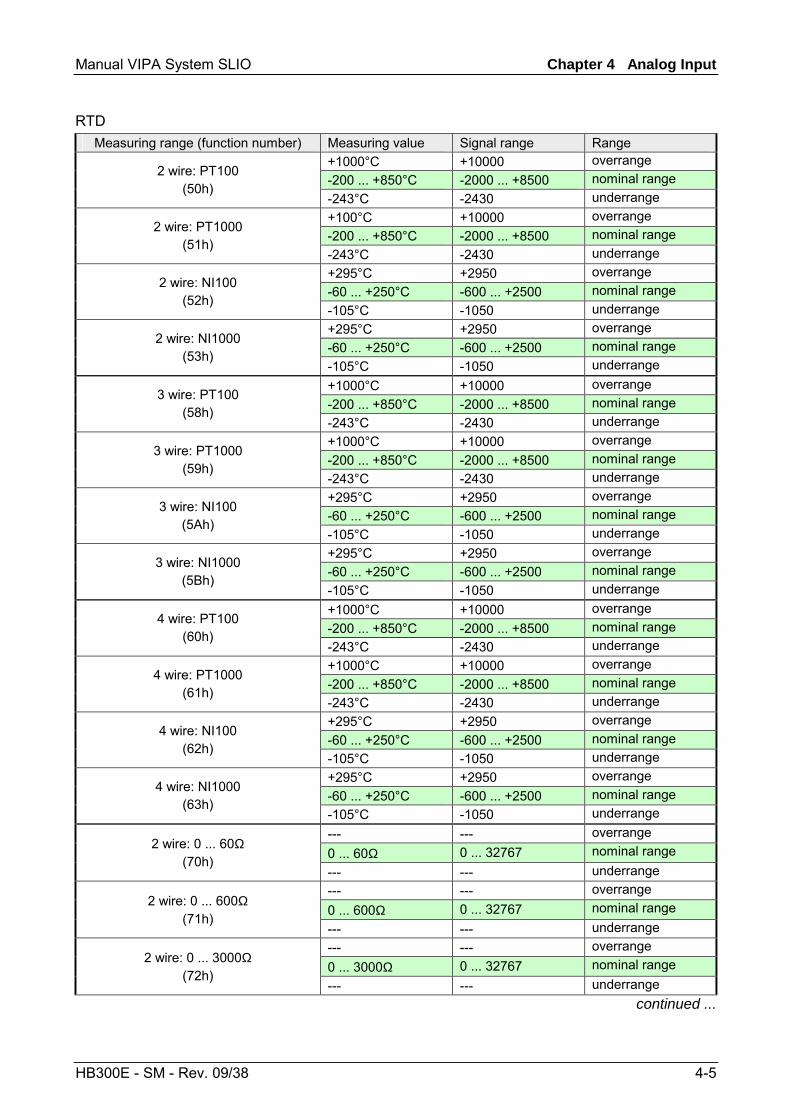
Measuring range (function number) Measuring value Signal range Range
+1000°C +10000 overrange -200 ... +850°C -2000 ... +8500 nominal range 2 wire: PT100
(50h) -243°C -2430 underrange +100°C +10000 overrange -200 ... +850°C -2000 ... +8500 nominal range 2 wire: PT1000
(51h) -243°C -2430 underrange +295°C +2950 overrange -60 ... +250°C -600 ... +2500 nominal range 2 wire: NI100
(52h) -105°C -1050 underrange +295°C +2950 overrange -60 ... +250°C -600 ... +2500 nominal range 2 wire: NI1000
(53h) -105°C -1050 underrange +1000°C +10000 overrange -200 ... +850°C -2000 ... +8500 nominal range 3 wire: PT100
(58h) -243°C -2430 underrange +1000°C +10000 overrange -200 ... +850°C -2000 ... +8500 nominal range 3 wire: PT1000
(59h) -243°C -2430 underrange +295°C +2950 overrange -60 ... +250°C -600 ... +2500 nominal range 3 wire: NI100
(5Ah) -105°C -1050 underrange +295°C +2950 overrange -60 ... +250°C -600 ... +2500 nominal range 3 wire: NI1000
(5Bh) -105°C -1050 underrange +1000°C +10000 overrange -200 ... +850°C -2000 ... +8500 nominal range 4 wire: PT100
(60h) -243°C -2430 underrange +1000°C +10000 overrange -200 ... +850°C -2000 ... +8500 nominal range 4 wire: PT1000
(61h) -243°C -2430 underrange +295°C +2950 overrange -60 ... +250°C -600 ... +2500 nominal range 4 wire: NI100
(62h) -105°C -1050 underrange +295°C +2950 overrange -60 ... +250°C -600 ... +2500 nominal range 4 wire: NI1000
(63h) -105°C -1050 underrange --- --- overrange 0 ... 60Ω 0 ... 32767 nominal range 2 wire: 0 ... 60Ω
(70h) --- --- underrange --- --- overrange 0 ... 600Ω 0 ... 32767 nominal range 2 wire: 0 ... 600Ω
(71h) --- --- underrange --- --- overrange 0 ... 3000Ω 0 ... 32767 nominal range 2 wire: 0 ... 3000Ω
(72h) --- --- underrange
continued ...
RTD
Chapter 4 Analog Input Manual VIPA System SLIO
4-6 HB300E - SM - Rev. 09/38
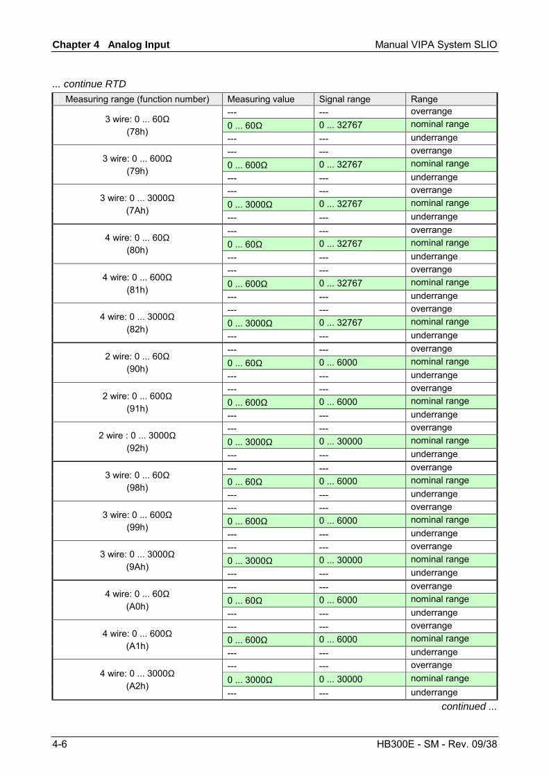
... continue RTD Measuring range (function number) Measuring value Signal range Range
--- --- overrange 0 ... 60Ω 0 ... 32767 nominal range 3 wire: 0 ... 60Ω
(78h) --- --- underrange --- --- overrange 0 ... 600Ω 0 ... 32767 nominal range 3 wire: 0 ... 600Ω
(79h) --- --- underrange --- --- overrange 0 ... 3000Ω 0 ... 32767 nominal range 3 wire: 0 ... 3000Ω
(7Ah) --- --- underrange --- --- overrange 0 ... 60Ω 0 ... 32767 nominal range 4 wire: 0 ... 60Ω
(80h) --- --- underrange --- --- overrange 0 ... 600Ω 0 ... 32767 nominal range 4 wire: 0 ... 600Ω
(81h) --- --- underrange --- --- overrange 0 ... 3000Ω 0 ... 32767 nominal range 4 wire: 0 ... 3000Ω
(82h) --- --- underrange --- --- overrange 0 ... 60Ω 0 ... 6000 nominal range 2 wire: 0 ... 60Ω
(90h) --- --- underrange --- --- overrange 0 ... 600Ω 0 ... 6000 nominal range 2 wire: 0 ... 600Ω
(91h) --- --- underrange --- --- overrange 0 ... 3000Ω 0 ... 30000 nominal range 2 wire : 0 ... 3000Ω
(92h) --- --- underrange --- --- overrange 0 ... 60Ω 0 ... 6000 nominal range 3 wire: 0 ... 60Ω
(98h) --- --- underrange --- --- overrange 0 ... 600Ω 0 ... 6000 nominal range 3 wire: 0 ... 600Ω
(99h) --- --- underrange --- --- overrange 0 ... 3000Ω 0 ... 30000 nominal range 3 wire: 0 ... 3000Ω
(9Ah) --- --- underrange --- --- overrange 0 ... 60Ω 0 ... 6000 nominal range 4 wire: 0 ... 60Ω
(A0h) --- --- underrange --- --- overrange 0 ... 600Ω 0 ... 6000 nominal range 4 wire: 0 ... 600Ω
(A1h) --- --- underrange --- --- overrange 0 ... 3000Ω 0 ... 30000 nominal range 4 wire: 0 ... 3000Ω
(A2h) --- --- underrange
continued ...
Manual VIPA System SLIO Chapter 4 Analog Input
HB300E - SM - Rev. 09/38 4-7
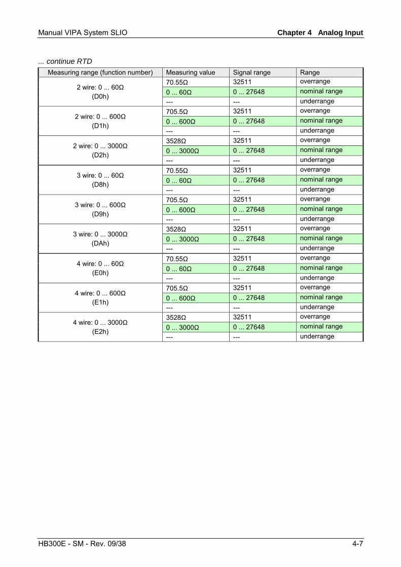
... continue RTD Measuring range (function number) Measuring value Signal range Range
70.55Ω 32511 overrange 0 ... 60Ω 0 ... 27648 nominal range 2 wire: 0 ... 60Ω
(D0h) --- --- underrange 705.5Ω 32511 overrange 0 ... 600Ω 0 ... 27648 nominal range 2 wire: 0 ... 600Ω
(D1h) --- --- underrange 3528Ω 32511 overrange 0 ... 3000Ω 0 ... 27648 nominal range 2 wire: 0 ... 3000Ω
(D2h) --- --- underrange 70.55Ω 32511 overrange 0 ... 60Ω 0 ... 27648 nominal range 3 wire: 0 ... 60Ω
(D8h) --- --- underrange 705.5Ω 32511 overrange 0 ... 600Ω 0 ... 27648 nominal range 3 wire: 0 ... 600Ω
(D9h) --- --- underrange 3528Ω 32511 overrange 0 ... 3000Ω 0 ... 27648 nominal range 3 wire: 0 ... 3000Ω
(DAh) --- --- underrange 70.55Ω 32511 overrange 0 ... 60Ω 0 ... 27648 nominal range 4 wire: 0 ... 60Ω
(E0h) --- --- underrange 705.5Ω 32511 overrange 0 ... 600Ω 0 ... 27648 nominal range 4 wire: 0 ... 600Ω
(E1h) --- --- underrange 3528Ω 32511 overrange 0 ... 3000Ω 0 ... 27648 nominal range 4 wire: 0 ... 3000Ω
(E2h) --- --- underrange

Chapter 4 Analog Input Manual VIPA System SLIO
4-8 HB300E - SM - Rev. 09/38
VIPA 031-1BB30 - AI 2x12Bit 0...10V
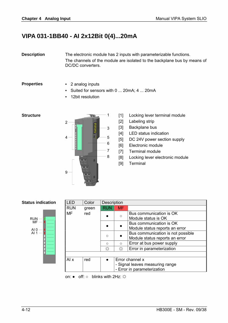
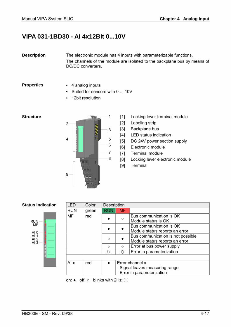
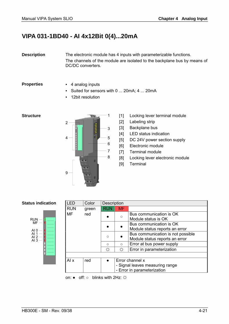
The electronic module has 2 inputs with parameterizable functions. The channels of the module are isolated to the backplane bus by means of DC/DC converters.
• 2 analog inputs • Suited for sensors with 0 ... 10V • 12bit resolution
1
3
546
78
9
2
[1] [2] [3] [4] [5] [6] [7] [8] [9]
Locking lever terminal module Labeling strip Backplane bus LED status indication DC 24V power section supply Electronic module Terminal module Locking lever electronic module Terminal
LED Color Description RUN green RUN MF MF red Bus communication is OK
Module status is OK Bus communication is OK
Module status reports an error Bus communication is not possible
Module status reports an error Error at bus power supply Error in parameterization
Status indication
RUNMF
AI 0AI 1
AI x red Error channel x - Signal leaves measuring range - Error in parameterization
on: off: blinks with 2Hz:
Description
Properties
Structure
Manual VIPA System SLIO Chapter 4 Analog Input
HB300E - SM - Rev. 09/38 4-9
For wires with a cross section of 0.08mm2 up to 2.5mm2.
2 6
3 7
4 8
1 51
2
3
4
5
6
7
8
DC24V0V
V V
AI
1
2
3
4
5
6
7
8
0 1
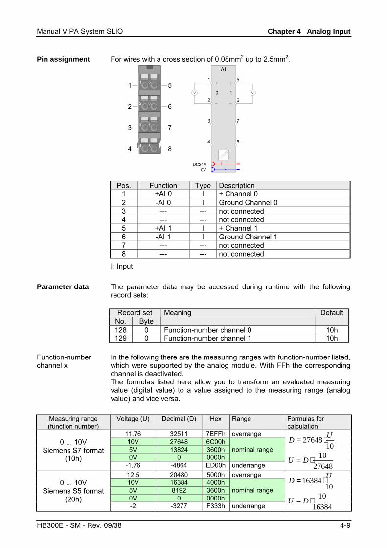
Pos. Function Type Description 1 +AI 0 I + Channel 0 2 -AI 0 I Ground Channel 0 3 --- --- not connected 4 --- --- not connected 5 +AI 1 I + Channel 1 6 -AI 1 I Ground Channel 1 7 --- --- not connected 8 --- --- not connected
I: Input The parameter data may be accessed during runtime with the following record sets:
Record set No. Byte
Meaning Default
128 0 Function-number channel 0 10h 129 0 Function-number channel 1 10h
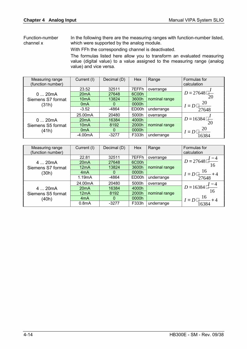
In the following there are the measuring ranges with function-number listed, which were supported by the analog module. With FFh the corresponding channel is deactivated. The formulas listed here allow you to transform an evaluated measuring value (digital value) to a value assigned to the measuring range (analog value) and vice versa.
Measuring range (function number)
Voltage (U) Decimal (D) Hex Range Formulas for calculation
11.76 32511 7EFFh overrange 10V 27648 6C00h 5V 13824 3600h 0V 0 0000h
nominal range 0 ... 10V
Siemens S7 format (10h)
-1.76 -4864 ED00h underrange
1027648 UD ⋅=
2764810⋅= DU
12.5 20480 5000h overrange 10V 16384 4000h 5V 8192 3600h 0V 0 0000h
nominal range 0 ... 10V
Siemens S5 format (20h)
-2 -3277 F333h underrange
1016384 UD ⋅=
1638410⋅= DU
Pin assignment
Parameter data
Function-number channel x
Chapter 4 Analog Input Manual VIPA System SLIO
4-10 HB300E - SM - Rev. 09/38
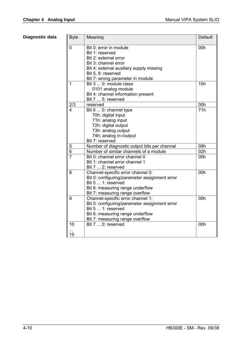
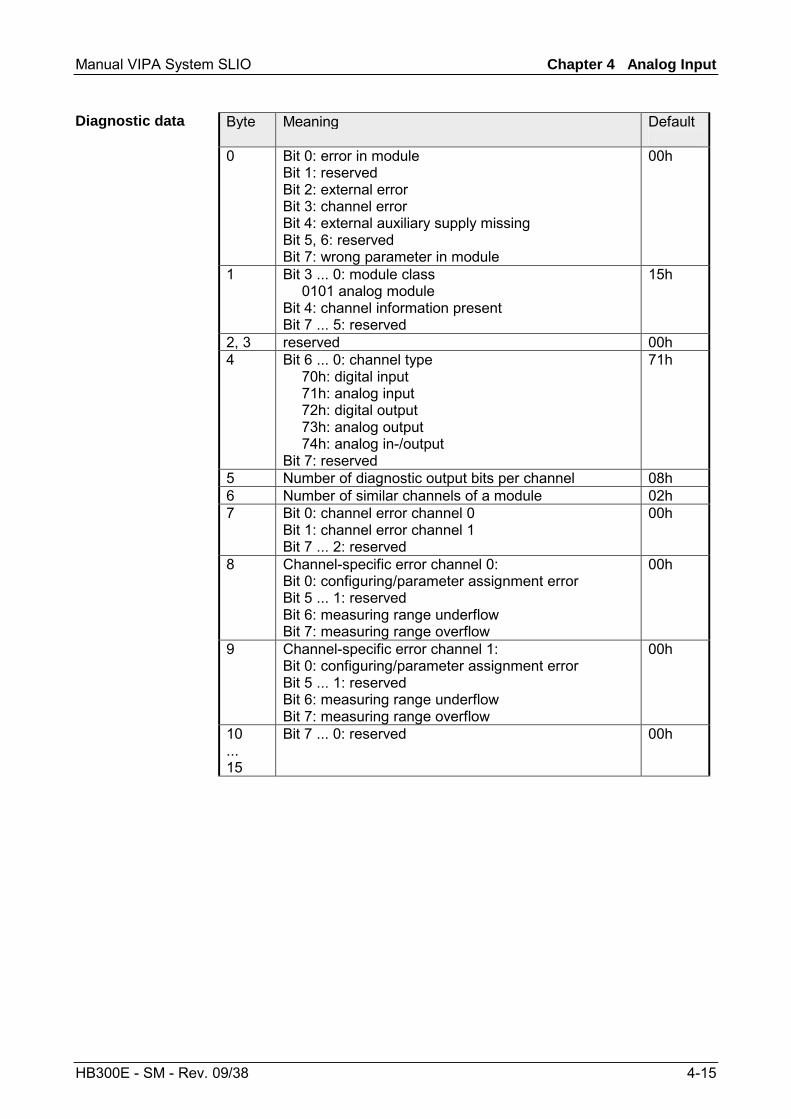
Byte Meaning Default
0 Bit 0: error in module Bit 1: reserved Bit 2: external error Bit 3: channel error Bit 4: external auxiliary supply missing Bit 5, 6: reserved Bit 7: wrong parameter in module
00h
1 Bit 3 ... 0: module class 0101 analog module Bit 4: channel information present Bit 7 ... 5: reserved
15h
2/3 reserved 00h 4 Bit 6 ... 0: channel type
70h: digital input 71h: analog input 72h: digital output 73h: analog output 74h: analog in-/output Bit 7: reserved
71h
5 Number of diagnostic output bits per channel 08h 6 Number of similar channels of a module 02h 7 Bit 0: channel error channel 0
Bit 1: channel error channel 1 Bit 7 ... 2: reserved
00h
8 Channel-specific error channel 0: Bit 0: configuring/parameter assignment error Bit 5 ... 1: reserved Bit 6: measuring range underflow Bit 7: measuring range overflow
00h
9 Channel-specific error channel 1: Bit 0: configuring/parameter assignment error Bit 5 ... 1: reserved Bit 6: measuring range underflow Bit 7: measuring range overflow
00h
10 ... 15
Bit 7 ... 0: reserved 00h
Diagnostic data
Manual VIPA System SLIO Chapter 4 Analog Input
HB300E - SM - Rev. 09/38 4-11
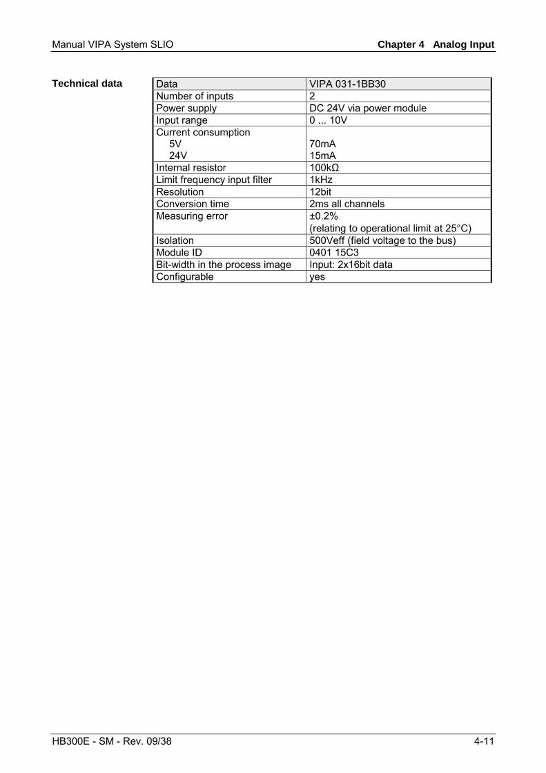
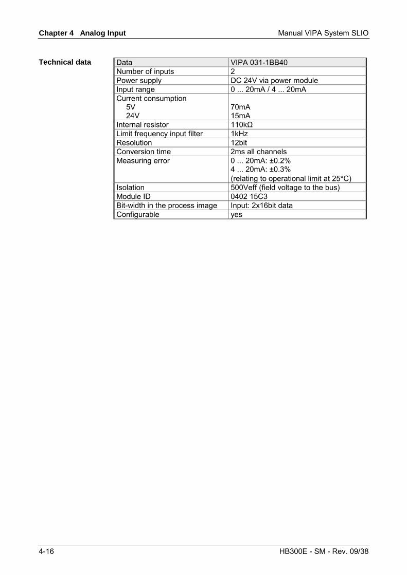
Data VIPA 031-1BB30 Number of inputs 2 Power supply DC 24V via power module Input range 0 ... 10V Current consumption 5V 24V
70mA 15mA
Internal resistor 100kΩ Limit frequency input filter 1kHz Resolution 12bit Conversion time 2ms all channels Measuring error ±0.2%
(relating to operational limit at 25°C) Isolation 500Veff (field voltage to the bus) Module ID 0401 15C3 Bit-width in the process image Input: 2x16bit data Configurable yes
Technical data
Chapter 4 Analog Input Manual VIPA System SLIO
4-12 HB300E - SM - Rev. 09/38
VIPA 031-1BB40 - AI 2x12Bit 0(4)...20mA
The electronic module has 2 inputs with parameterizable functions. The channels of the module are isolated to the backplane bus by means of DC/DC converters.
• 2 analog inputs • Suited for sensors with 0 ... 20mA; 4 ... 20mA • 12bit resolution
1
3
546
78
9
2
[1] [2] [3] [4] [5] [6] [7] [8] [9]
Locking lever terminal module Labeling strip Backplane bus LED status indication DC 24V power section supply Electronic module Terminal module Locking lever electronic module Terminal
LED Color Description RUN green RUN MF MF red Bus communication is OK
Module status is OK Bus communication is OK
Module status reports an error Bus communication is not possible
Module status reports an error Error at bus power supply Error in parameterization
Status indication
RUNMF
AI 0AI 1
AI x red Error channel x - Signal leaves measuring range - Error in parameterization
on: off: blinks with 2Hz:
Description
Properties
Structure
Manual VIPA System SLIO Chapter 4 Analog Input
HB300E - SM - Rev. 09/38 4-13
For wires with a cross section of 0.08mm2 up to 2.5mm2.
2 6
3 7
4 8
1 51
2
3
4
5
6
7
8
DC24V0V
A A
AI
1
2
3
4
5
6
7
8
0 1
Pos. Function Type Description 1 +AI 0 I + Channel 0 2 -AI 0 I Ground Channel 0 3 --- --- not connected 4 --- --- not connected 5 +AI 1 I + Channel 1 6 -AI 1 I Ground Channel 1 7 --- --- not connected 8 --- --- not connected
I: Input
The parameter data may be accessed during runtime with the following record sets:
Record set No. Byte
Meaning Default
128 0 Function-number channel 0 31h 129 0 Function-number channel 1 31h
Pin assignment
Parameter data
Chapter 4 Analog Input Manual VIPA System SLIO
4-14 HB300E - SM - Rev. 09/38
In the following there are the measuring ranges with function-number listed, which were supported by the analog module. With FFh the corresponding channel is deactivated. The formulas listed here allow you to transform an evaluated measuring value (digital value) to a value assigned to the measuring range (analog value) and vice versa.
Measuring range (function number)
Current (I) Decimal (D) Hex Range Formulas for calculation
23.52 32511 7EFFh overrange 20mA 27648 6C00h 10mA 13824 3600h 0mA 0 0000h
nominal range 0 ... 20mA
Siemens S7 format (31h)
-3.52 -4864 ED00h underrange
2027648 ID ⋅=
2764820⋅= DI
25.00mA 20480 5000h overrange 20mA 16384 4000h 10mA 8192 2000h 0mA 0 0000h
nominal range 0 ... 20mA
Siemens S5 format (41h)
-4.00mA -3277 F333h underrange
2016384 ID ⋅=
1638420⋅= DI
Measuring range (function number)
Current (I) Decimal (D) Hex Range Formulas for calculation
22.81 32511 7EFFh overrange 20mA 27648 6C00h 12mA 13824 3600h 4mA 0 0000h
nominal range 4 ... 20mA
Siemens S7 format (30h)
1.19mA -4864 ED00h underrange
16427648 −⋅= ID
427648
16 +⋅= DI
24.00mA 20480 5000h overrange 20mA 16384 4000h 12mA 8192 2000h 4mA 0 0000h
nominal range 4 ... 20mA
Siemens S5 format (40h)
0.8mA -3277 F333h underrange
16416384 −⋅= ID
416384
16 +⋅= DI
Function-number channel x
Manual VIPA System SLIO Chapter 4 Analog Input
HB300E - SM - Rev. 09/38 4-15
Byte Meaning Default
0 Bit 0: error in module Bit 1: reserved Bit 2: external error Bit 3: channel error Bit 4: external auxiliary supply missing Bit 5, 6: reserved Bit 7: wrong parameter in module
00h
1 Bit 3 ... 0: module class 0101 analog module Bit 4: channel information present Bit 7 ... 5: reserved
15h
2, 3 reserved 00h 4 Bit 6 ... 0: channel type
70h: digital input 71h: analog input 72h: digital output 73h: analog output 74h: analog in-/output Bit 7: reserved
71h
5 Number of diagnostic output bits per channel 08h 6 Number of similar channels of a module 02h 7 Bit 0: channel error channel 0
Bit 1: channel error channel 1 Bit 7 ... 2: reserved
00h
8 Channel-specific error channel 0: Bit 0: configuring/parameter assignment error Bit 5 ... 1: reserved Bit 6: measuring range underflow Bit 7: measuring range overflow
00h
9 Channel-specific error channel 1: Bit 0: configuring/parameter assignment error Bit 5 ... 1: reserved Bit 6: measuring range underflow Bit 7: measuring range overflow
00h
10 ... 15
Bit 7 ... 0: reserved 00h
Diagnostic data
Chapter 4 Analog Input Manual VIPA System SLIO
4-16 HB300E - SM - Rev. 09/38
Data VIPA 031-1BB40 Number of inputs 2 Power supply DC 24V via power module Input range 0 ... 20mA / 4 ... 20mA Current consumption 5V 24V
70mA 15mA
Internal resistor 110kΩ Limit frequency input filter 1kHz Resolution 12bit Conversion time 2ms all channels Measuring error 0 ... 20mA: ±0.2%
4 ... 20mA: ±0.3% (relating to operational limit at 25°C)
Isolation 500Veff (field voltage to the bus) Module ID 0402 15C3 Bit-width in the process image Input: 2x16bit data Configurable yes
Technical data
Manual VIPA System SLIO Chapter 4 Analog Input
HB300E - SM - Rev. 09/38 4-17
VIPA 031-1BD30 - AI 4x12Bit 0...10V
The electronic module has 4 inputs with parameterizable functions. The channels of the module are isolated to the backplane bus by means of DC/DC converters.
• 4 analog inputs • Suited for sensors with 0 ... 10V • 12bit resolution
1
3
546
78
9
2
[1] [2] [3] [4] [5] [6] [7] [8] [9]
Locking lever terminal module Labeling strip Backplane bus LED status indication DC 24V power section supply Electronic module Terminal module Locking lever electronic module Terminal
LED Color Description RUN green RUN MF MF red Bus communication is OK
Module status is OK Bus communication is OK
Module status reports an error Bus communication is not possible
Module status reports an error Error at bus power supply Error in parameterization
Status indication
RUNMF
AI 0AI 1AI 2AI 3
AI x red Error channel x - Signal leaves measuring range - Error in parameterization
on: off: blinks with 2Hz:
Description
Properties
Structure
Chapter 4 Analog Input Manual VIPA System SLIO
4-18 HB300E - SM - Rev. 09/38
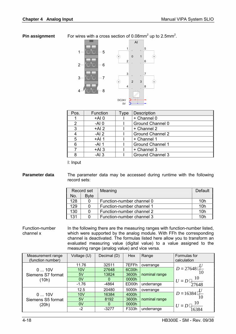
For wires with a cross section of 0.08mm2 up to 2.5mm2.
2 6
3 7
4 8
1 51
2
3
4
5
6
7
8
DC24V0V
V V
V
AI
1
2
3
4
5
6
7
8
0 1
2 3 V
Pos. Function Type Description 1 +AI 0 I + Channel 0 2 -AI 0 I Ground Channel 0 3 +AI 2 I + Channel 2 4 -AI 2 I Ground Channel 2 5 +AI 1 I + Channel 1 6 -AI 1 I Ground Channel 1 7 +AI 3 I + Channel 3 8 -AI 3 I Ground Channel 3
I: Input The parameter data may be accessed during runtime with the following record sets:
Record set No. Byte
Meaning Default
128 0 Function-number channel 0 10h 129 0 Function-number channel 1 10h 130 0 Function-number channel 2 10h 131 0 Function-number channel 3 10h
In the following there are the measuring ranges with function-number listed, which were supported by the analog module. With FFh the corresponding channel is deactivated. The formulas listed here allow you to transform an evaluated measuring value (digital value) to a value assigned to the measuring range (analog value) and vice versa.
Measurement range (function number)
Voltage (U) Decimal (D) Hex Range Formulas for calculation
11.76 32511 7EFFh overrange 10V 27648 6C00h 5V 13824 3600h 0V 0 0000h
nominal range 0 ... 10V
Siemens S7 format (10h)
-1.76 -4864 ED00h underrange
1027648 UD ⋅=
2764810⋅= DU
12.5 20480 5000h overrange 10V 16384 4000h 5V 8192 3600h 0V 0 0000h
nominal range 0 ... 10V
Siemens S5 format (20h)
-2 -3277 F333h underrange
1016384 UD ⋅=
1638410⋅= DU
Pin assignment
Parameter data
Function-number channel x
Manual VIPA System SLIO Chapter 4 Analog Input
HB300E - SM - Rev. 09/38 4-19
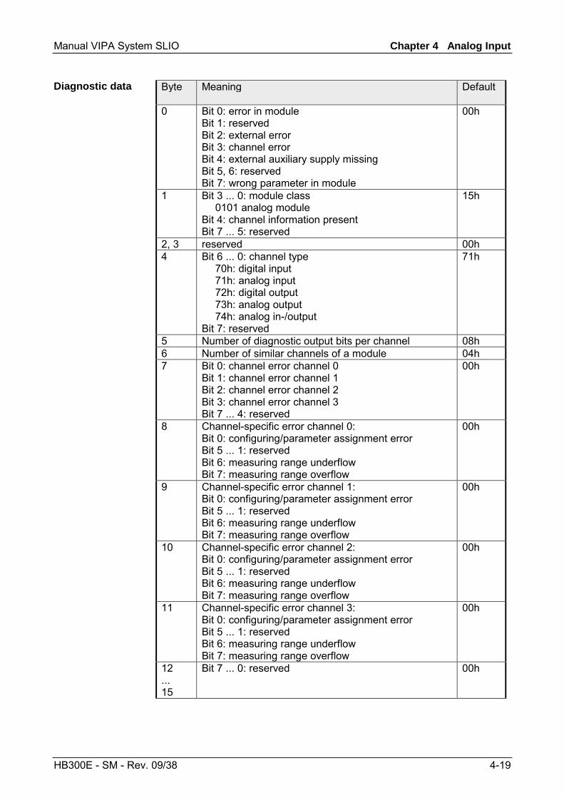
Byte Meaning Default
0 Bit 0: error in module Bit 1: reserved Bit 2: external error Bit 3: channel error Bit 4: external auxiliary supply missing Bit 5, 6: reserved Bit 7: wrong parameter in module
00h
1 Bit 3 ... 0: module class 0101 analog module Bit 4: channel information present Bit 7 ... 5: reserved
15h
2, 3 reserved 00h 4 Bit 6 ... 0: channel type
70h: digital input 71h: analog input 72h: digital output 73h: analog output 74h: analog in-/output Bit 7: reserved
71h
5 Number of diagnostic output bits per channel 08h 6 Number of similar channels of a module 04h 7 Bit 0: channel error channel 0
Bit 1: channel error channel 1 Bit 2: channel error channel 2 Bit 3: channel error channel 3 Bit 7 ... 4: reserved
00h
8 Channel-specific error channel 0: Bit 0: configuring/parameter assignment error Bit 5 ... 1: reserved Bit 6: measuring range underflow Bit 7: measuring range overflow
00h
9 Channel-specific error channel 1: Bit 0: configuring/parameter assignment error Bit 5 ... 1: reserved Bit 6: measuring range underflow Bit 7: measuring range overflow
00h
10 Channel-specific error channel 2: Bit 0: configuring/parameter assignment error Bit 5 ... 1: reserved Bit 6: measuring range underflow Bit 7: measuring range overflow
00h
11 Channel-specific error channel 3: Bit 0: configuring/parameter assignment error Bit 5 ... 1: reserved Bit 6: measuring range underflow Bit 7: measuring range overflow
00h
12 ... 15
Bit 7 ... 0: reserved 00h
Diagnostic data
Chapter 4 Analog Input Manual VIPA System SLIO
4-20 HB300E - SM - Rev. 09/38
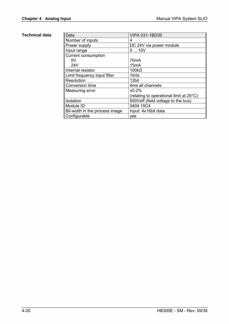
Data VIPA 031-1BD30 Number of inputs 4 Power supply DC 24V via power module Input range 0 ... 10V Current consumption 5V 24V
70mA 15mA
Internal resistor 100kΩ Limit frequency input filter 1kHz Resolution 12bit Conversion time 4ms all channels Measuring error ±0.2%
(relating to operational limit at 25°C) Isolation 500Veff (field voltage to the bus) Module ID 0404 15C4 Bit-width in the process image Input: 4x16bit data Configurable yes
Technical data
Manual VIPA System SLIO Chapter 4 Analog Input
HB300E - SM - Rev. 09/38 4-21
VIPA 031-1BD40 - AI 4x12Bit 0(4)...20mA
The electronic module has 4 inputs with parameterizable functions. The channels of the module are isolated to the backplane bus by means of DC/DC converters.
• 4 analog inputs • Suited for sensors with 0 ... 20mA; 4 ... 20mA • 12bit resolution
1
3
546
78
9
2
[1] [2] [3] [4] [5] [6] [7] [8] [9]
Locking lever terminal module Labeling strip Backplane bus LED status indication DC 24V power section supply Electronic module Terminal module Locking lever electronic module Terminal
LED Color Description RUN green RUN MF MF red Bus communication is OK
Module status is OK Bus communication is OK
Module status reports an error Bus communication is not possible
Module status reports an error Error at bus power supply Error in parameterization
Status indication
RUNMF
AI 0AI 1AI 2AI 3
AI x red Error channel x - Signal leaves measuring range - Error in parameterization
on: off: blinks with 2Hz:
Description
Properties
Structure
Chapter 4 Analog Input Manual VIPA System SLIO
4-22 HB300E - SM - Rev. 09/38
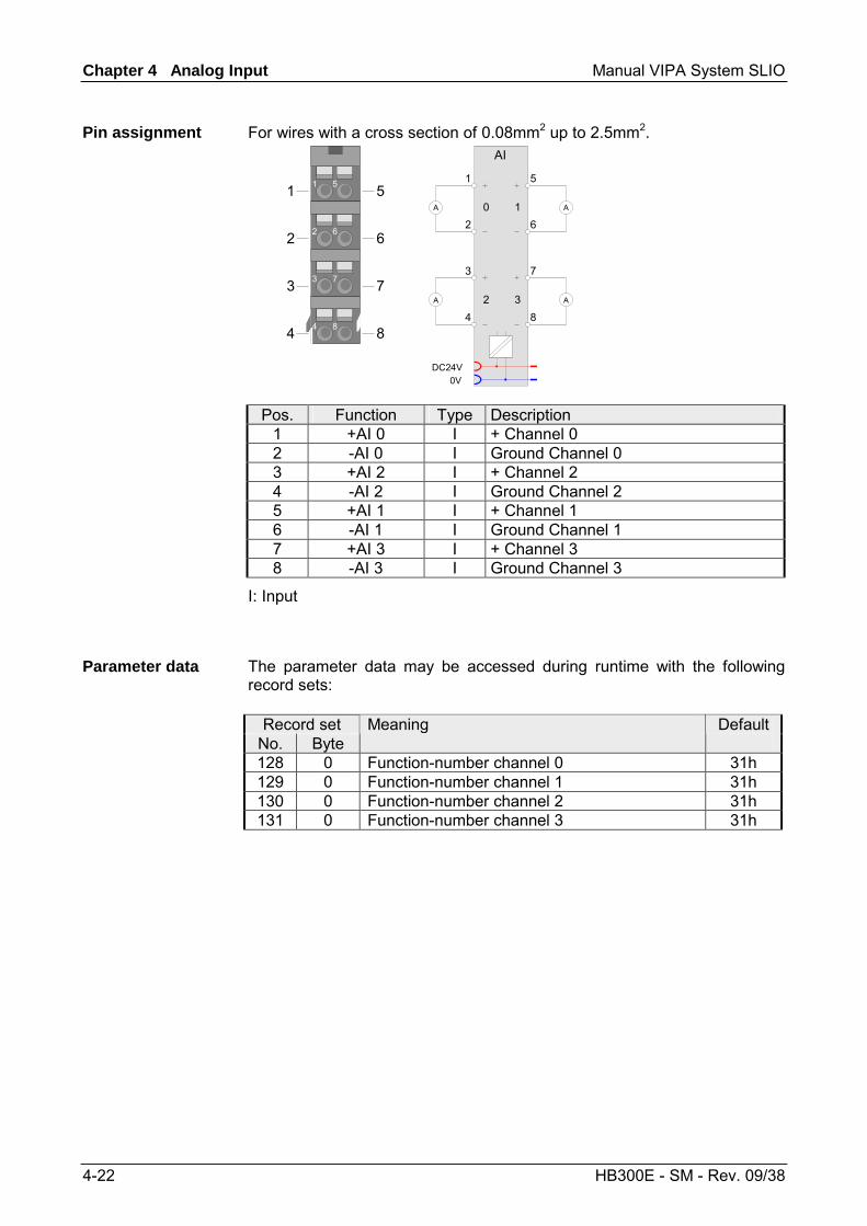
For wires with a cross section of 0.08mm2 up to 2.5mm2.
2 6
3 7
4 8
1 51
2
3
4
5
6
7
8
DC24V0V
A A
A
AI
1
2
3
4
5
6
7
8
0 1
2 3 A
Pos. Function Type Description 1 +AI 0 I + Channel 0 2 -AI 0 I Ground Channel 0 3 +AI 2 I + Channel 2 4 -AI 2 I Ground Channel 2 5 +AI 1 I + Channel 1 6 -AI 1 I Ground Channel 1 7 +AI 3 I + Channel 3 8 -AI 3 I Ground Channel 3
I: Input
The parameter data may be accessed during runtime with the following record sets:
Record set No. Byte
Meaning Default
128 0 Function-number channel 0 31h 129 0 Function-number channel 1 31h 130 0 Function-number channel 2 31h 131 0 Function-number channel 3 31h
Pin assignment
Parameter data
Manual VIPA System SLIO Chapter 4 Analog Input
HB300E - SM - Rev. 09/38 4-23
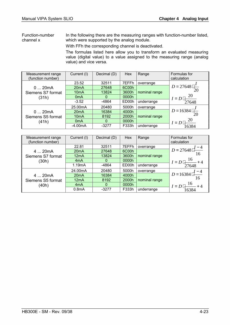
In the following there are the measuring ranges with function-number listed, which were supported by the analog module. With FFh the corresponding channel is deactivated. The formulas listed here allow you to transform an evaluated measuring value (digital value) to a value assigned to the measuring range (analog value) and vice versa.
Measurement range (function number)
Current (I) Decimal (D) Hex Range Formulas for calculation
23.52 32511 7EFFh overrange 20mA 27648 6C00h 10mA 13824 3600h 0mA 0 0000h
nominal range 0 ... 20mA
Siemens S7 format (31h)
-3.52 -4864 ED00h underrange
2027648 ID ⋅=
2764820⋅= DI
25.00mA 20480 5000h overrange 20mA 16384 4000h 10mA 8192 2000h 0mA 0 0000h
nominal range 0 ... 20mA
Siemens S5 format (41h)
-4.00mA -3277 F333h underrange
2016384 ID ⋅=
1638420⋅= DI
Measurement range (function number)
Current (I) Decimal (D) Hex Range Formulas for calculation
22.81 32511 7EFFh overrange 20mA 27648 6C00h 12mA 13824 3600h 4mA 0 0000h
nominal range 4 ... 20mA
Siemens S7 format (30h)
1.19mA -4864 ED00h underrange
16427648 −⋅= ID
427648
16 +⋅= DI
24.00mA 20480 5000h overrange 20mA 16384 4000h 12mA 8192 2000h 4mA 0 0000h
nominal range 4 ... 20mA
Siemens S5 format (40h)
0.8mA -3277 F333h underrange
16416384 −⋅= ID
416384
16 +⋅= DI
Function-number channel x
Chapter 4 Analog Input Manual VIPA System SLIO
4-24 HB300E - SM - Rev. 09/38
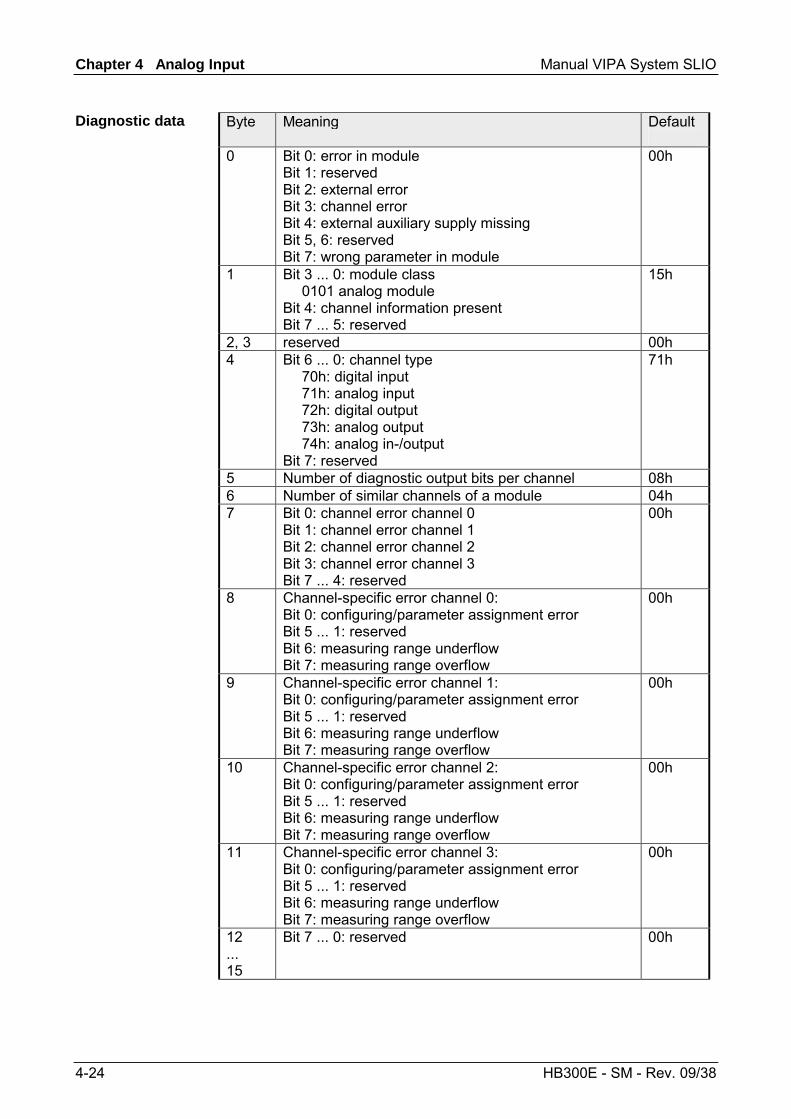
Byte Meaning Default
0 Bit 0: error in module Bit 1: reserved Bit 2: external error Bit 3: channel error Bit 4: external auxiliary supply missing Bit 5, 6: reserved Bit 7: wrong parameter in module
00h
1 Bit 3 ... 0: module class 0101 analog module Bit 4: channel information present Bit 7 ... 5: reserved
15h
2, 3 reserved 00h 4 Bit 6 ... 0: channel type
70h: digital input 71h: analog input 72h: digital output 73h: analog output 74h: analog in-/output Bit 7: reserved
71h
5 Number of diagnostic output bits per channel 08h 6 Number of similar channels of a module 04h 7 Bit 0: channel error channel 0
Bit 1: channel error channel 1 Bit 2: channel error channel 2 Bit 3: channel error channel 3 Bit 7 ... 4: reserved
00h
8 Channel-specific error channel 0: Bit 0: configuring/parameter assignment error Bit 5 ... 1: reserved Bit 6: measuring range underflow Bit 7: measuring range overflow
00h
9 Channel-specific error channel 1: Bit 0: configuring/parameter assignment error Bit 5 ... 1: reserved Bit 6: measuring range underflow Bit 7: measuring range overflow
00h
10 Channel-specific error channel 2: Bit 0: configuring/parameter assignment error Bit 5 ... 1: reserved Bit 6: measuring range underflow Bit 7: measuring range overflow
00h
11 Channel-specific error channel 3: Bit 0: configuring/parameter assignment error Bit 5 ... 1: reserved Bit 6: measuring range underflow Bit 7: measuring range overflow
00h
12 ... 15
Bit 7 ... 0: reserved 00h
Diagnostic data
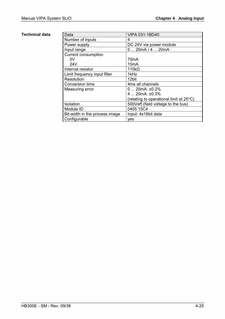
Manual VIPA System SLIO Chapter 4 Analog Input
HB300E - SM - Rev. 09/38 4-25
Data VIPA 031-1BD40 Number of inputs 4 Power supply DC 24V via power module Input range 0 ... 20mA / 4 ... 20mA Current consumption 5V 24V
70mA 15mA
Internal resistor 110kΩ Limit frequency input filter 1kHz Resolution 12bit Conversion time 4ms all channels Measuring error 0 ... 20mA: ±0.2%
4 ... 20mA: ±0.3% (relating to operational limit at 25°C)
Isolation 500Veff (field voltage to the bus) Module ID 0405 15C4 Bit-width in the process image Input: 4x16bit data Configurable yes
Technical data
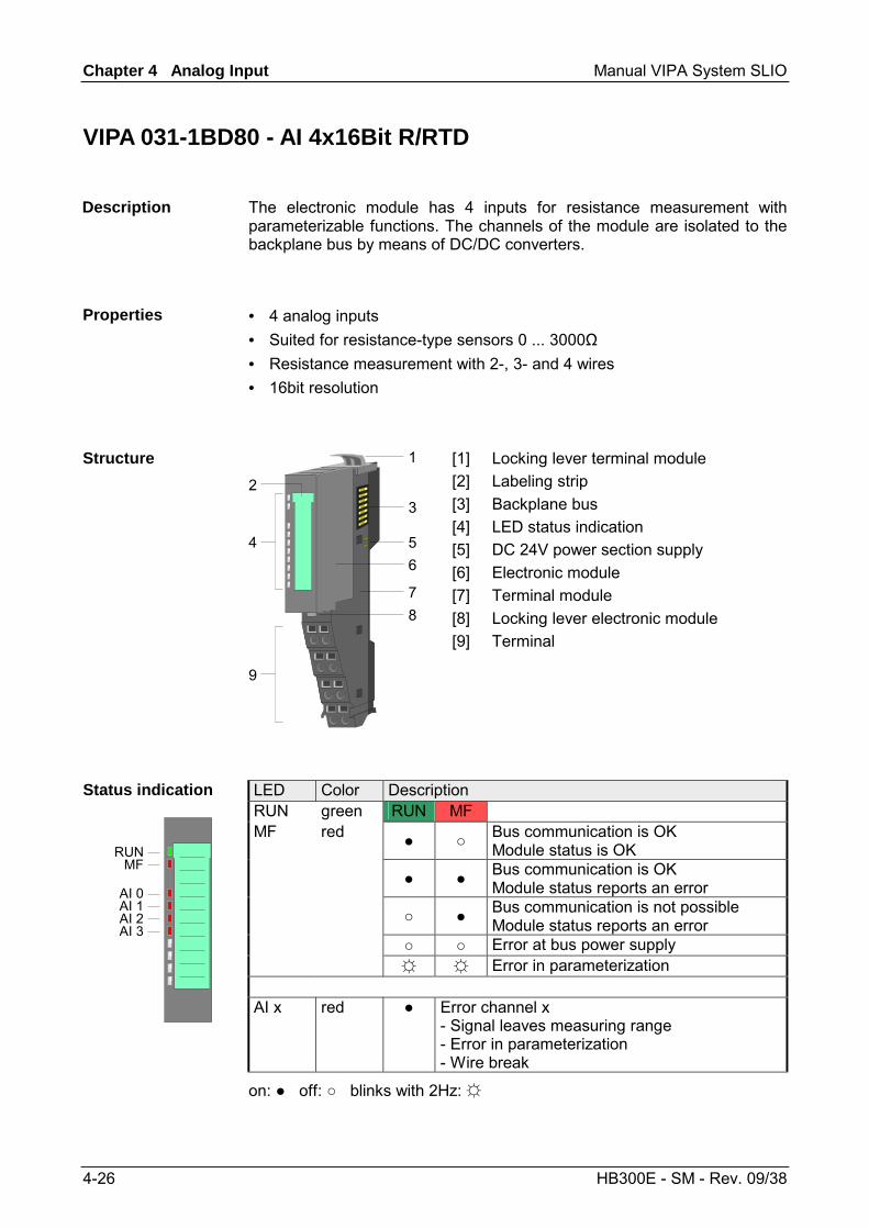
Chapter 4 Analog Input Manual VIPA System SLIO
4-26 HB300E - SM - Rev. 09/38
VIPA 031-1BD80 - AI 4x16Bit R/RTD
The electronic module has 4 inputs for resistance measurement with parameterizable functions. The channels of the module are isolated to the backplane bus by means of DC/DC converters.
• 4 analog inputs • Suited for resistance-type sensors 0 ... 3000Ω • Resistance measurement with 2-, 3- and 4 wires • 16bit resolution
1
3
546
78
9
2
[1] [2] [3] [4] [5] [6] [7] [8] [9]
Locking lever terminal module Labeling strip Backplane bus LED status indication DC 24V power section supply Electronic module Terminal module Locking lever electronic module Terminal
LED Color Description RUN green RUN MF MF red Bus communication is OK
Module status is OK Bus communication is OK
Module status reports an error Bus communication is not possible
Module status reports an error Error at bus power supply Error in parameterization
Status indication
RUNMF
AI 0AI 1AI 2AI 3
AI x red Error channel x - Signal leaves measuring range - Error in parameterization - Wire break
on: off: blinks with 2Hz:
Description
Properties
Structure
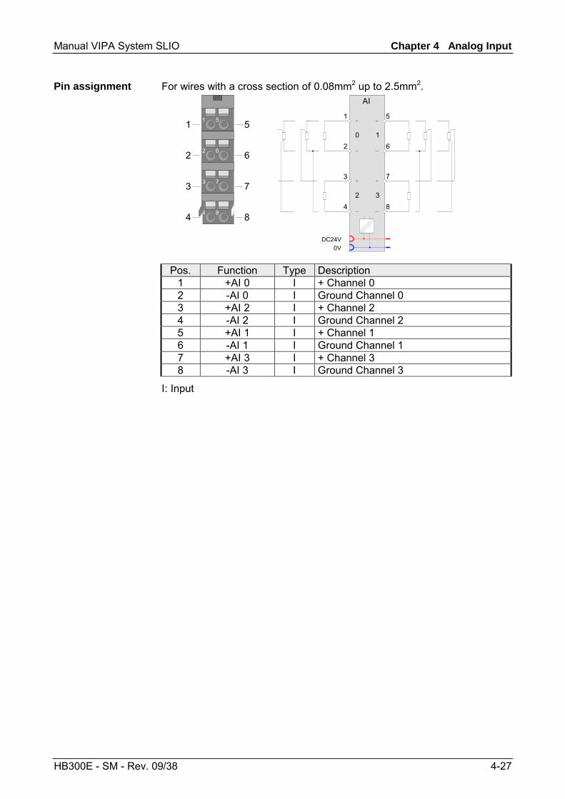
Manual VIPA System SLIO Chapter 4 Analog Input
HB300E - SM - Rev. 09/38 4-27
For wires with a cross section of 0.08mm2 up to 2.5mm2.
2 6
3 7
4 8
1 51
2
3
4
5
6
7
8
2 6
3 7
4 8
1 5
AI
DC24V0V
AI
1
2
3
4
5
6
7
8
0 1
2 3
Pos. Function Type Description 1 +AI 0 I + Channel 0 2 -AI 0 I Ground Channel 0 3 +AI 2 I + Channel 2 4 -AI 2 I Ground Channel 2 5 +AI 1 I + Channel 1 6 -AI 1 I Ground Channel 1 7 +AI 3 I + Channel 3 8 -AI 3 I Ground Channel 3
I: Input
Pin assignment
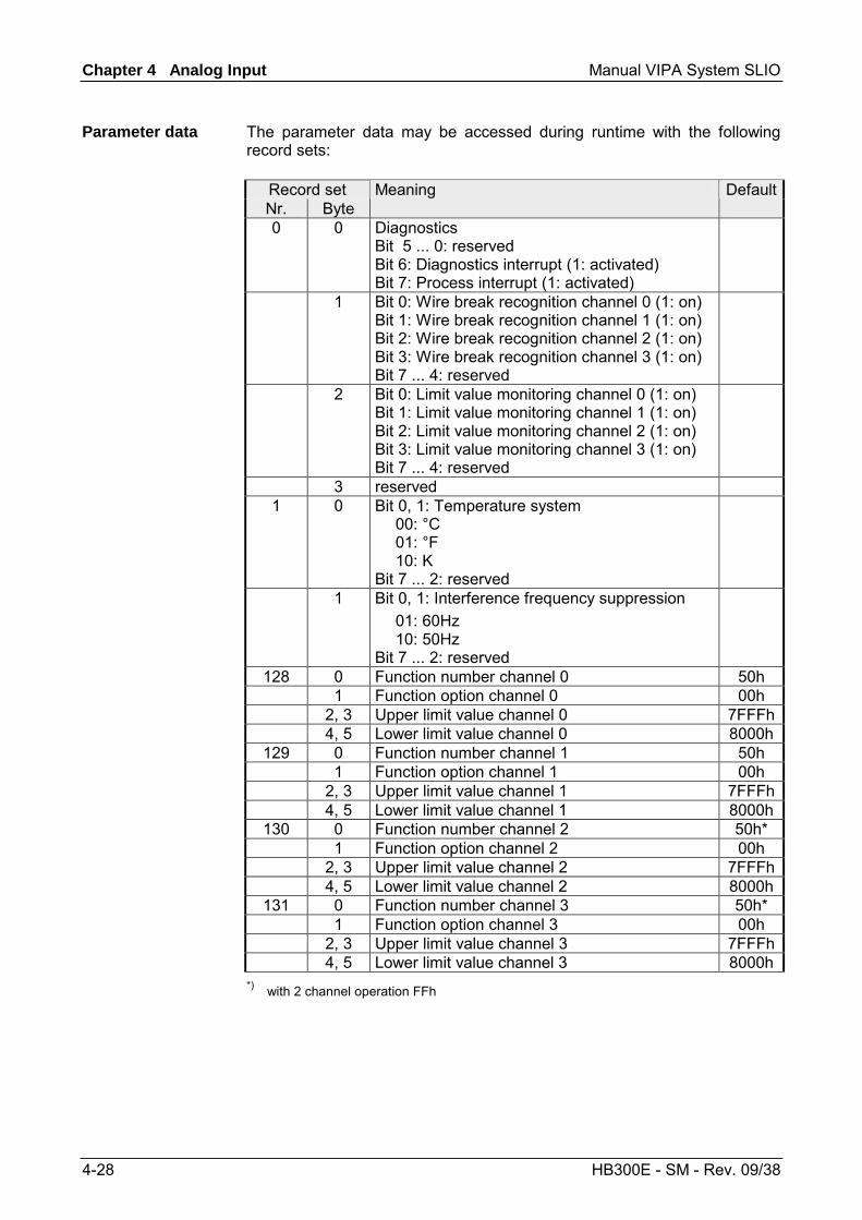
Chapter 4 Analog Input Manual VIPA System SLIO
4-28 HB300E - SM - Rev. 09/38
The parameter data may be accessed during runtime with the following record sets:
Record set Nr. Byte
Meaning Default
0 0 Diagnostics Bit 5 ... 0: reserved Bit 6: Diagnostics interrupt (1: activated) Bit 7: Process interrupt (1: activated)
1 Bit 0: Wire break recognition channel 0 (1: on) Bit 1: Wire break recognition channel 1 (1: on) Bit 2: Wire break recognition channel 2 (1: on) Bit 3: Wire break recognition channel 3 (1: on) Bit 7 ... 4: reserved
2 Bit 0: Limit value monitoring channel 0 (1: on) Bit 1: Limit value monitoring channel 1 (1: on) Bit 2: Limit value monitoring channel 2 (1: on) Bit 3: Limit value monitoring channel 3 (1: on) Bit 7 ... 4: reserved
3 reserved 1 0 Bit 0, 1: Temperature system
00: °C 01: °F 10: K Bit 7 ... 2: reserved
1 Bit 0, 1: Interference frequency suppression 01: 60Hz 10: 50Hz Bit 7 ... 2: reserved
128 0 Function number channel 0 50h 1 Function option channel 0 00h 2, 3 Upper limit value channel 0 7FFFh 4, 5 Lower limit value channel 0 8000h
129 0 Function number channel 1 50h 1 Function option channel 1 00h 2, 3 Upper limit value channel 1 7FFFh 4, 5 Lower limit value channel 1 8000h
130 0 Function number channel 2 50h* 1 Function option channel 2 00h 2, 3 Upper limit value channel 2 7FFFh 4, 5 Lower limit value channel 2 8000h
131 0 Function number channel 3 50h* 1 Function option channel 3 00h 2, 3 Upper limit value channel 3 7FFFh 4, 5 Lower limit value channel 3 8000h
*) with 2 channel operation FFh
Parameter data
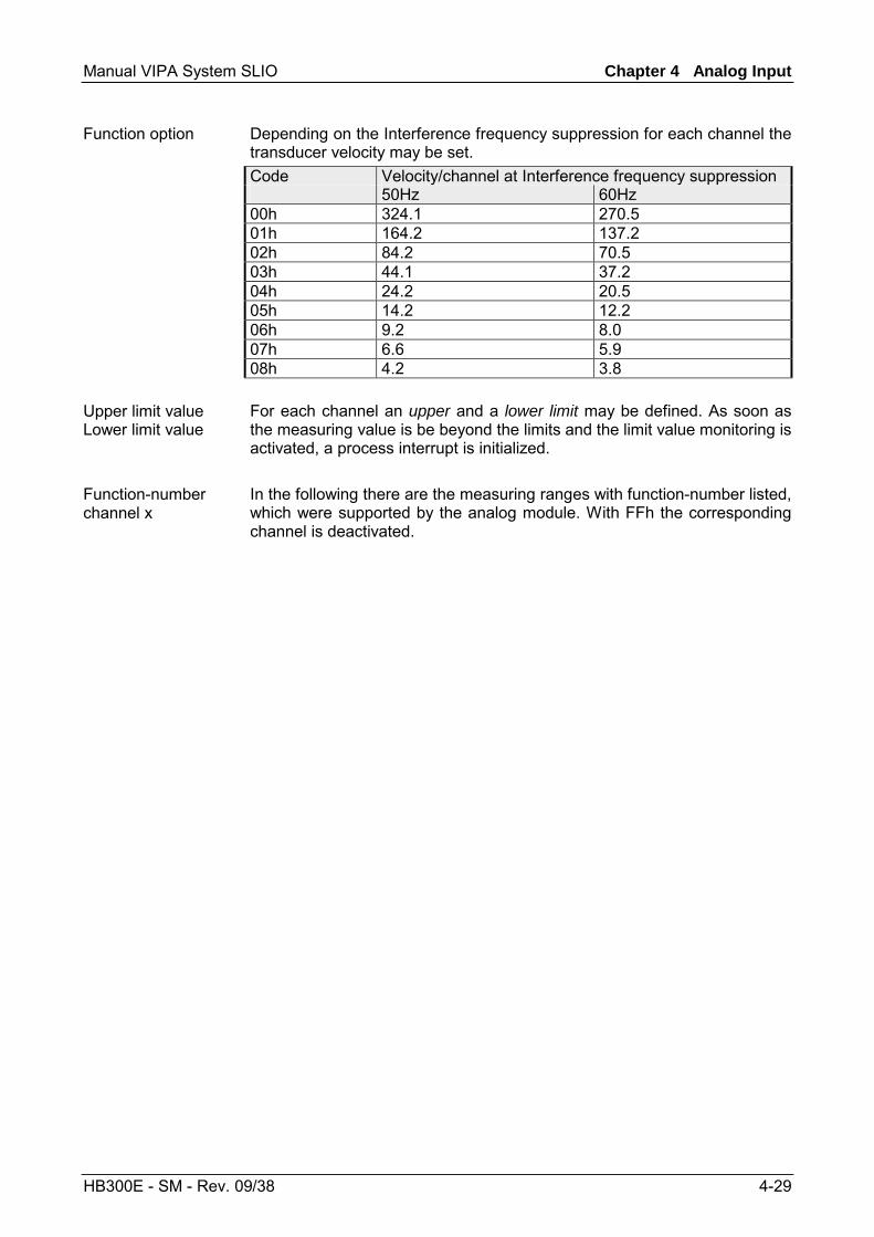
Manual VIPA System SLIO Chapter 4 Analog Input
HB300E - SM - Rev. 09/38 4-29
Depending on the Interference frequency suppression for each channel the transducer velocity may be set. Code Velocity/channel at Interference frequency suppression 50Hz 60Hz 00h 324.1 270.5 01h 164.2 137.2 02h 84.2 70.5 03h 44.1 37.2 04h 24.2 20.5 05h 14.2 12.2 06h 9.2 8.0 07h 6.6 5.9 08h 4.2 3.8 For each channel an upper and a lower limit may be defined. As soon as the measuring value is be beyond the limits and the limit value monitoring is activated, a process interrupt is initialized. In the following there are the measuring ranges with function-number listed, which were supported by the analog module. With FFh the corresponding channel is deactivated.
Function option
Upper limit value Lower limit value
Function-number channel x
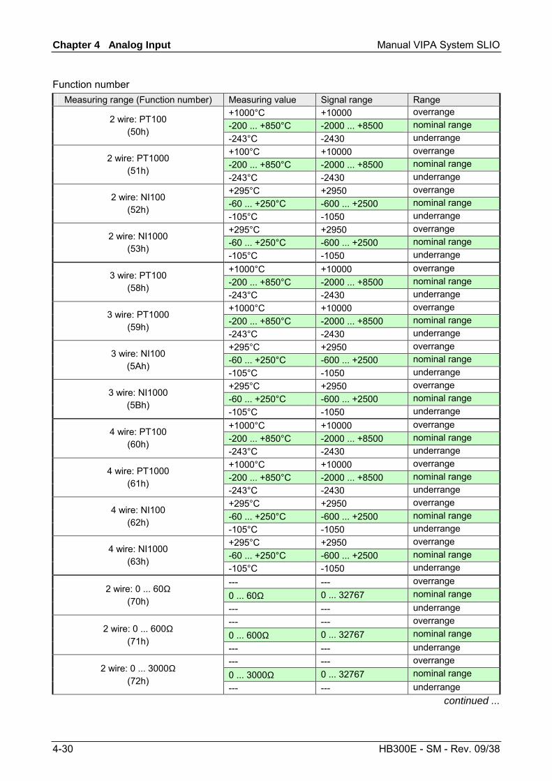
Chapter 4 Analog Input Manual VIPA System SLIO
4-30 HB300E - SM - Rev. 09/38
Measuring range (Function number) Measuring value Signal range Range
+1000°C +10000 overrange -200 ... +850°C -2000 ... +8500 nominal range 2 wire: PT100
(50h) -243°C -2430 underrange +100°C +10000 overrange -200 ... +850°C -2000 ... +8500 nominal range 2 wire: PT1000
(51h) -243°C -2430 underrange +295°C +2950 overrange -60 ... +250°C -600 ... +2500 nominal range 2 wire: NI100
(52h) -105°C -1050 underrange +295°C +2950 overrange -60 ... +250°C -600 ... +2500 nominal range 2 wire: NI1000
(53h) -105°C -1050 underrange +1000°C +10000 overrange -200 ... +850°C -2000 ... +8500 nominal range 3 wire: PT100
(58h) -243°C -2430 underrange +1000°C +10000 overrange -200 ... +850°C -2000 ... +8500 nominal range 3 wire: PT1000
(59h) -243°C -2430 underrange +295°C +2950 overrange -60 ... +250°C -600 ... +2500 nominal range 3 wire: NI100
(5Ah) -105°C -1050 underrange +295°C +2950 overrange -60 ... +250°C -600 ... +2500 nominal range 3 wire: NI1000
(5Bh) -105°C -1050 underrange +1000°C +10000 overrange -200 ... +850°C -2000 ... +8500 nominal range 4 wire: PT100
(60h) -243°C -2430 underrange +1000°C +10000 overrange -200 ... +850°C -2000 ... +8500 nominal range 4 wire: PT1000
(61h) -243°C -2430 underrange +295°C +2950 overrange -60 ... +250°C -600 ... +2500 nominal range 4 wire: NI100
(62h) -105°C -1050 underrange +295°C +2950 overrange -60 ... +250°C -600 ... +2500 nominal range 4 wire: NI1000
(63h) -105°C -1050 underrange --- --- overrange 0 ... 60Ω 0 ... 32767 nominal range 2 wire: 0 ... 60Ω
(70h) --- --- underrange --- --- overrange 0 ... 600Ω 0 ... 32767 nominal range 2 wire: 0 ... 600Ω
(71h) --- --- underrange --- --- overrange 0 ... 3000Ω 0 ... 32767 nominal range 2 wire: 0 ... 3000Ω
(72h) --- --- underrange
continued ...
Function number
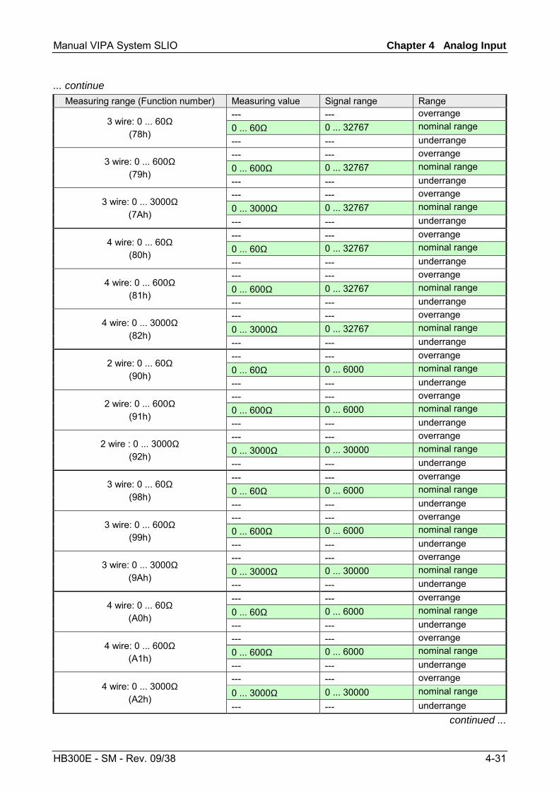
Manual VIPA System SLIO Chapter 4 Analog Input
HB300E - SM - Rev. 09/38 4-31
... continue Measuring range (Function number) Measuring value Signal range Range
--- --- overrange 0 ... 60Ω 0 ... 32767 nominal range 3 wire: 0 ... 60Ω
(78h) --- --- underrange --- --- overrange 0 ... 600Ω 0 ... 32767 nominal range 3 wire: 0 ... 600Ω
(79h) --- --- underrange --- --- overrange 0 ... 3000Ω 0 ... 32767 nominal range 3 wire: 0 ... 3000Ω
(7Ah) --- --- underrange --- --- overrange 0 ... 60Ω 0 ... 32767 nominal range 4 wire: 0 ... 60Ω
(80h) --- --- underrange --- --- overrange 0 ... 600Ω 0 ... 32767 nominal range 4 wire: 0 ... 600Ω
(81h) --- --- underrange --- --- overrange 0 ... 3000Ω 0 ... 32767 nominal range 4 wire: 0 ... 3000Ω
(82h) --- --- underrange --- --- overrange 0 ... 60Ω 0 ... 6000 nominal range 2 wire: 0 ... 60Ω
(90h) --- --- underrange --- --- overrange 0 ... 600Ω 0 ... 6000 nominal range 2 wire: 0 ... 600Ω
(91h) --- --- underrange --- --- overrange 0 ... 3000Ω 0 ... 30000 nominal range 2 wire : 0 ... 3000Ω
(92h) --- --- underrange --- --- overrange 0 ... 60Ω 0 ... 6000 nominal range 3 wire: 0 ... 60Ω
(98h) --- --- underrange --- --- overrange 0 ... 600Ω 0 ... 6000 nominal range 3 wire: 0 ... 600Ω
(99h) --- --- underrange --- --- overrange 0 ... 3000Ω 0 ... 30000 nominal range 3 wire: 0 ... 3000Ω
(9Ah) --- --- underrange --- --- overrange 0 ... 60Ω 0 ... 6000 nominal range 4 wire: 0 ... 60Ω
(A0h) --- --- underrange --- --- overrange 0 ... 600Ω 0 ... 6000 nominal range 4 wire: 0 ... 600Ω
(A1h) --- --- underrange --- --- overrange 0 ... 3000Ω 0 ... 30000 nominal range 4 wire: 0 ... 3000Ω
(A2h) --- --- underrange
continued ...
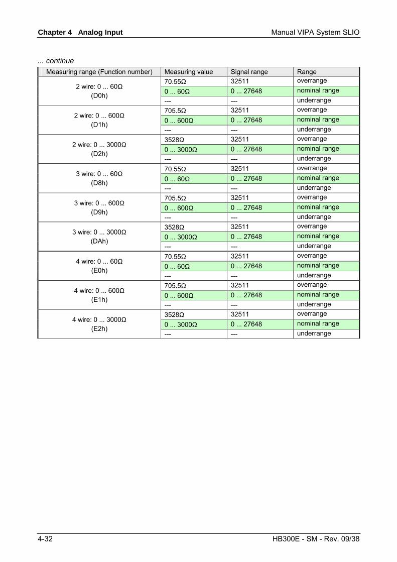
Chapter 4 Analog Input Manual VIPA System SLIO
4-32 HB300E - SM - Rev. 09/38
... continue Measuring range (Function number) Measuring value Signal range Range
70.55Ω 32511 overrange 0 ... 60Ω 0 ... 27648 nominal range 2 wire: 0 ... 60Ω
(D0h) --- --- underrange 705.5Ω 32511 overrange 0 ... 600Ω 0 ... 27648 nominal range 2 wire: 0 ... 600Ω
(D1h) --- --- underrange 3528Ω 32511 overrange 0 ... 3000Ω 0 ... 27648 nominal range 2 wire: 0 ... 3000Ω
(D2h) --- --- underrange 70.55Ω 32511 overrange 0 ... 60Ω 0 ... 27648 nominal range 3 wire: 0 ... 60Ω
(D8h) --- --- underrange 705.5Ω 32511 overrange 0 ... 600Ω 0 ... 27648 nominal range 3 wire: 0 ... 600Ω
(D9h) --- --- underrange 3528Ω 32511 overrange 0 ... 3000Ω 0 ... 27648 nominal range 3 wire: 0 ... 3000Ω
(DAh) --- --- underrange 70.55Ω 32511 overrange 0 ... 60Ω 0 ... 27648 nominal range 4 wire: 0 ... 60Ω
(E0h) --- --- underrange 705.5Ω 32511 overrange 0 ... 600Ω 0 ... 27648 nominal range 4 wire: 0 ... 600Ω
(E1h) --- --- underrange 3528Ω 32511 overrange 0 ... 3000Ω 0 ... 27648 nominal range 4 wire: 0 ... 3000Ω
(E2h) --- --- underrange
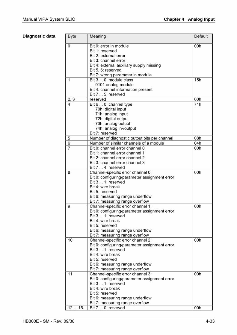
Manual VIPA System SLIO Chapter 4 Analog Input
HB300E - SM - Rev. 09/38 4-33
Byte Meaning Default
0 Bit 0: error in module Bit 1: reserved Bit 2: external error Bit 3: channel error Bit 4: external auxiliary supply missing Bit 5, 6: reserved Bit 7: wrong parameter in module
00h
1 Bit 3 ... 0: module class 0101 analog module Bit 4: channel information present Bit 7 ... 5: reserved
15h
2, 3 reserved 00h 4 Bit 6 ... 0: channel type
70h: digital input 71h: analog input 72h: digital output 73h: analog output 74h: analog in-/output Bit 7: reserved
71h
5 Number of diagnostic output bits per channel 08h 6 Number of similar channels of a module 04h 7 Bit 0: channel error channel 0
Bit 1: channel error channel 1 Bit 2: channel error channel 2 Bit 3: channel error channel 3 Bit 7 ... 4: reserved
00h
8 Channel-specific error channel 0: Bit 0: configuring/parameter assignment error Bit 3 ... 1: reserved Bit 4: wire break Bit 5: reserved Bit 6: measuring range underflow Bit 7: measuring range overflow
00h
9 Channel-specific error channel 1: Bit 0: configuring/parameter assignment error Bit 3 ... 1: reserved Bit 4: wire break Bit 5: reserved Bit 6: measuring range underflow Bit 7: measuring range overflow
00h
10 Channel-specific error channel 2: Bit 0: configuring/parameter assignment error Bit 3 ... 1: reserved Bit 4: wire break Bit 5: reserved Bit 6: measuring range underflow Bit 7: measuring range overflow
00h
11 Channel-specific error channel 3: Bit 0: configuring/parameter assignment error Bit 3 ... 1: reserved Bit 4: wire break Bit 5: reserved Bit 6: measuring range underflow Bit 7: measuring range overflow
00h
12 ... 15 Bit 7 ... 0: reserved 00h
Diagnostic data
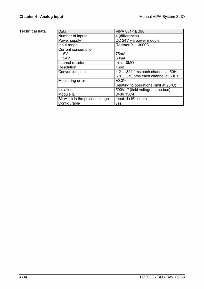
Chapter 4 Analog Input Manual VIPA System SLIO
4-34 HB300E - SM - Rev. 09/38
Data VIPA 031-1BD80 Number of inputs 4 (differential) Power supply DC 24V via power module Input range Resistor 0 ... 3000Ω Current consumption 5V 24V
75mA 30mA
Internal resistor min. 10MΩ Resolution 16bit Conversion time 4.2 ... 324.1ms each channel at 50Hz
3.8 ... 270.5ms each channel at 60Hz Measuring error ±0.3%
(relating to operational limit at 25°C) Isolation 500Veff (field voltage to the bus) Module ID 0406 15C4 Bit-width in the process image Input: 4x16bit data Configurable yes
Technical data
Manual VIPA System SLIO Chapter 5 Analog Output
HB300E - SM - Rev. 09/38 5-1
Chapter 5 Analog Output
After the introduction to the analog output and the list of the output ranges the description of the analog output modules of the System SLIO will be found here.
Topic Page Chapter 5 Analog Output ................................................................. 5-1
General ................................................................................................ 5-2 Analog value ........................................................................................ 5-3 Output ranges ...................................................................................... 5-4 VIPA 032-1BB30 - AO 2x12Bit 0...10V................................................. 5-5 VIPA 032-1BB40 - AO 2x12Bit 0(4)...20mA.......................................... 5-9 VIPA 032-1BD30 - AO 4x12Bit 0...10V............................................... 5-14 VIPA 032-1BD40 - AO 4x12Bit 0(4)...20mA........................................ 5-19
Overview
Content
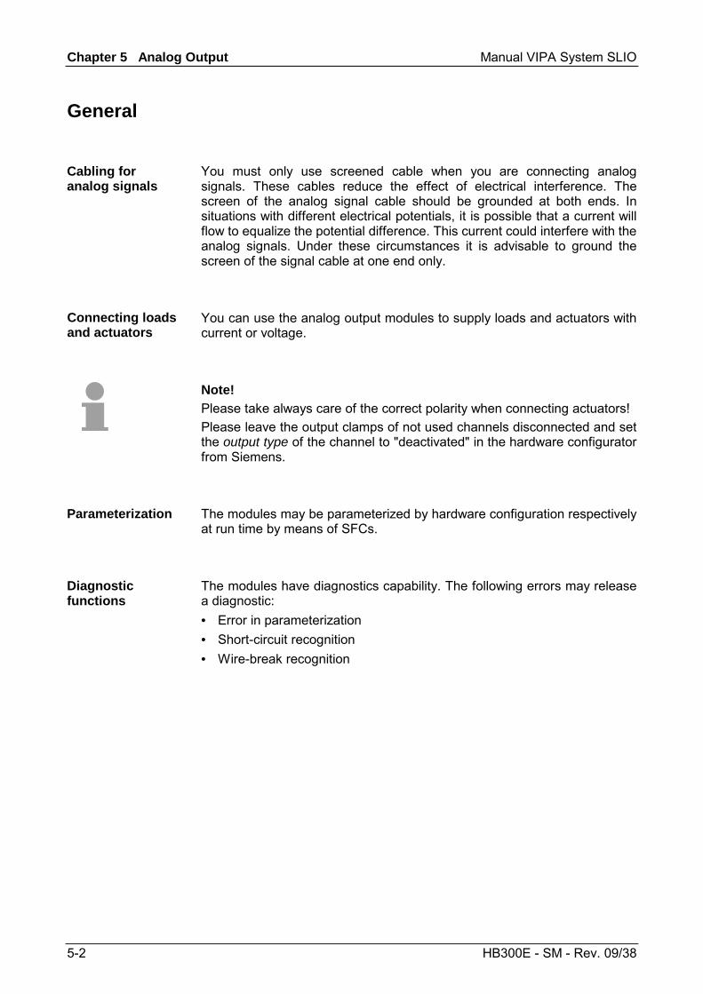
Chapter 5 Analog Output Manual VIPA System SLIO
5-2 HB300E - SM - Rev. 09/38
General
You must only use screened cable when you are connecting analog signals. These cables reduce the effect of electrical interference. The screen of the analog signal cable should be grounded at both ends. In situations with different electrical potentials, it is possible that a current will flow to equalize the potential difference. This current could interfere with the analog signals. Under these circumstances it is advisable to ground the screen of the signal cable at one end only.
You can use the analog output modules to supply loads and actuators with current or voltage.
Note! Please take always care of the correct polarity when connecting actuators! Please leave the output clamps of not used channels disconnected and set the output type of the channel to "deactivated" in the hardware configurator from Siemens.
The modules may be parameterized by hardware configuration respectively at run time by means of SFCs.
The modules have diagnostics capability. The following errors may release a diagnostic: • Error in parameterization • Short-circuit recognition • Wire-break recognition
Cabling for analog signals
Connecting loads and actuators
Parameterization
Diagnostic functions
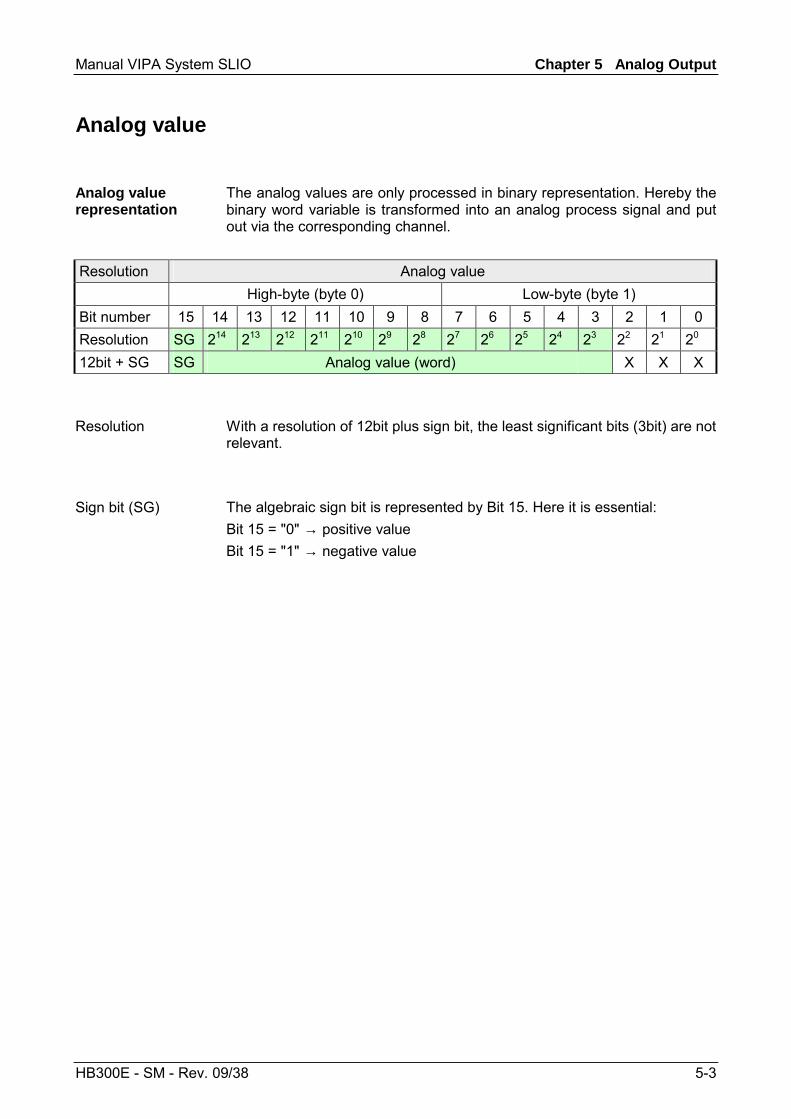
Manual VIPA System SLIO Chapter 5 Analog Output
HB300E - SM - Rev. 09/38 5-3
Analog value
The analog values are only processed in binary representation. Hereby the binary word variable is transformed into an analog process signal and put out via the corresponding channel.
Resolution Analog value High-byte (byte 0) Low-byte (byte 1) Bit number 15 14 13 12 11 10 9 8 7 6 5 4 3 2 1 0 Resolution SG 214 213 212 211 210 29 28 27 26 25 24 23 22 21 20 12bit + SG SG Analog value (word) X X X
With a resolution of 12bit plus sign bit, the least significant bits (3bit) are not relevant.
The algebraic sign bit is represented by Bit 15. Here it is essential: Bit 15 = "0" → positive value Bit 15 = "1" → negative value
Analog value representation
Resolution
Sign bit (SG)
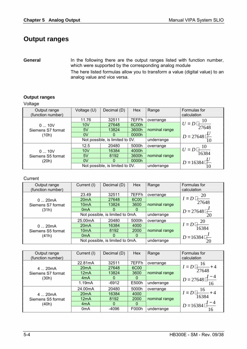
Chapter 5 Analog Output Manual VIPA System SLIO
5-4 HB300E - SM - Rev. 09/38
Output ranges
In the following there are the output ranges listed with function number, which were supported by the corresponding analog module The here listed formulas allow you to transform a value (digital value) to an analog value and vice versa.
Output range (function number)
Voltage (U) Decimal (D) Hex Range Formulas for calculation
11.76 32511 7EFFh overrange 10V 27648 6C00h 5V 13824 3600h 0V 0 0000h
nominal range 0 ... 10V
Siemens S7 format (10h)
Not possible, is limited to 0V. underrange
2764810⋅= DU
1027648 UD ⋅=
12.5 20480 5000h overrange 10V 16384 4000h 5V 8192 3600h 0V 0 0000h
nominal range 0 ... 10V
Siemens S5 format (20h)
Not possible, is limited to 0V. underrange
1638410⋅= DU
1016384 UD ⋅=
Output range (function number)
Current (I) Decimal (D) Hex Range Formulas for calculation
23.49 32511 7EFFh overrange 20mA 27648 6C00 10mA 13824 3600 0mA 0 0
nominal range 0 ... 20mA
Siemens S7 format (31h)
Not possible, is limited to 0mA. underrange
2764820⋅= DI
2027648 ID ⋅=
25.00mA 20480 5000h overrange 20mA 16384 4000 10mA 8192 2000 0mA 0 0
nominal range 0 ... 20mA
Siemens S5 format (41h)
Not possible, is limited to 0mA. underrange
1638420⋅= DI
2016384 ID ⋅=
Output range
(function number) Current (I) Decimal (D) Hex Range Formulas for
calculation 22.81mA 32511 7EFFh overrange
20mA 27648 6C00 12mA 13824 3600 4mA 0 0
nominal range 4 ... 20mA
Siemens S7 format (30h)
1.19mA -6912 E500h underrange
427648
16 +⋅= DI
16427648 −⋅= ID
24.00mA 20480 5000h overrange 20mA 16384 4000 12mA 8192 2000 4mA 0 0
nominal range 4 ... 20mA
Siemens S5 format (40h)
0mA -4096 F000h underrange
416384
16 +⋅= DI
16416384 −⋅= ID
General
Output ranges Voltage
Current
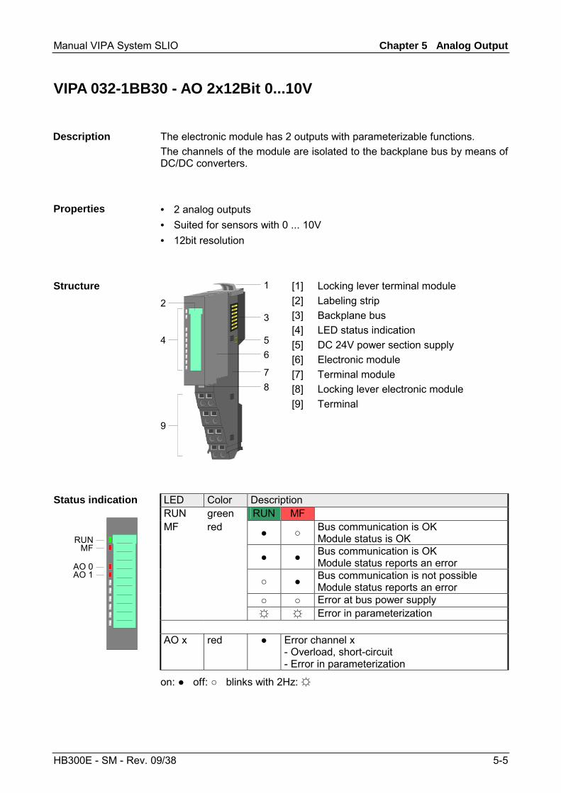
Manual VIPA System SLIO Chapter 5 Analog Output
HB300E - SM - Rev. 09/38 5-5
VIPA 032-1BB30 - AO 2x12Bit 0...10V
The electronic module has 2 outputs with parameterizable functions. The channels of the module are isolated to the backplane bus by means of DC/DC converters.
• 2 analog outputs • Suited for sensors with 0 ... 10V • 12bit resolution
1
3
546
78
9
2
[1] [2] [3] [4] [5] [6] [7] [8] [9]
Locking lever terminal module Labeling strip Backplane bus LED status indication DC 24V power section supply Electronic module Terminal module Locking lever electronic module Terminal
LED Color Description RUN green RUN MF MF red Bus communication is OK
Module status is OK Bus communication is OK
Module status reports an error Bus communication is not possible
Module status reports an error Error at bus power supply Error in parameterization
Status indication
RUNMF
AO 0AO 1
AO x red Error channel x - Overload, short-circuit - Error in parameterization
on: off: blinks with 2Hz:
Description
Properties
Structure
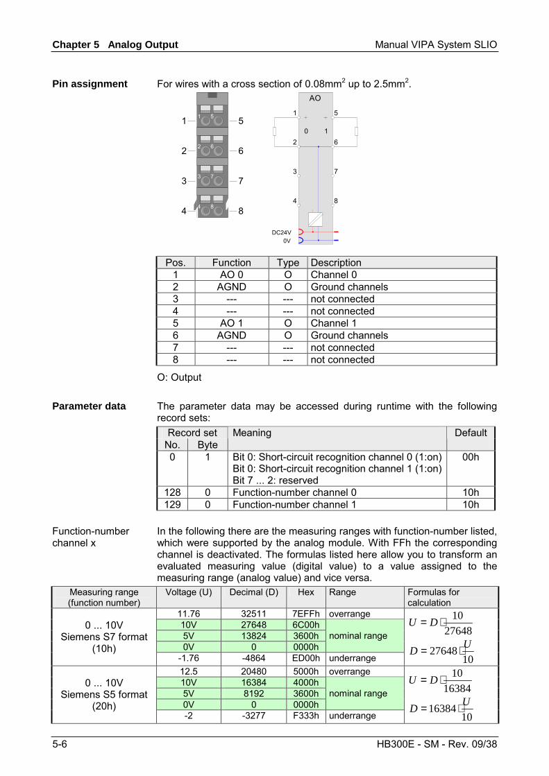
Chapter 5 Analog Output Manual VIPA System SLIO
5-6 HB300E - SM - Rev. 09/38
For wires with a cross section of 0.08mm2 up to 2.5mm2.
2 6
3 7
4 8
1 51
2
3
4
5
6
7
8
DC24V0V
AO
1
2
3
4
5
6
7
8
0 1
Pos. Function Type Description 1 AO 0 O Channel 0 2 AGND O Ground channels 3 --- --- not connected 4 --- --- not connected 5 AO 1 O Channel 1 6 AGND O Ground channels 7 --- --- not connected 8 --- --- not connected
O: Output The parameter data may be accessed during runtime with the following record sets:
Record set No. Byte
Meaning Default
0 1 Bit 0: Short-circuit recognition channel 0 (1:on) Bit 0: Short-circuit recognition channel 1 (1:on) Bit 7 ... 2: reserved
00h
128 0 Function-number channel 0 10h 129 0 Function-number channel 1 10h
In the following there are the measuring ranges with function-number listed, which were supported by the analog module. With FFh the corresponding channel is deactivated. The formulas listed here allow you to transform an evaluated measuring value (digital value) to a value assigned to the measuring range (analog value) and vice versa.
Measuring range (function number)
Voltage (U) Decimal (D) Hex Range Formulas for calculation
11.76 32511 7EFFh overrange 10V 27648 6C00h 5V 13824 3600h 0V 0 0000h
nominal range 0 ... 10V
Siemens S7 format (10h)
-1.76 -4864 ED00h underrange
2764810⋅= DU
1027648 UD ⋅=
12.5 20480 5000h overrange 10V 16384 4000h 5V 8192 3600h 0V 0 0000h
nominal range 0 ... 10V
Siemens S5 format (20h)
-2 -3277 F333h underrange
1638410⋅= DU
1016384 UD ⋅=
Pin assignment
Parameter data
Function-number channel x
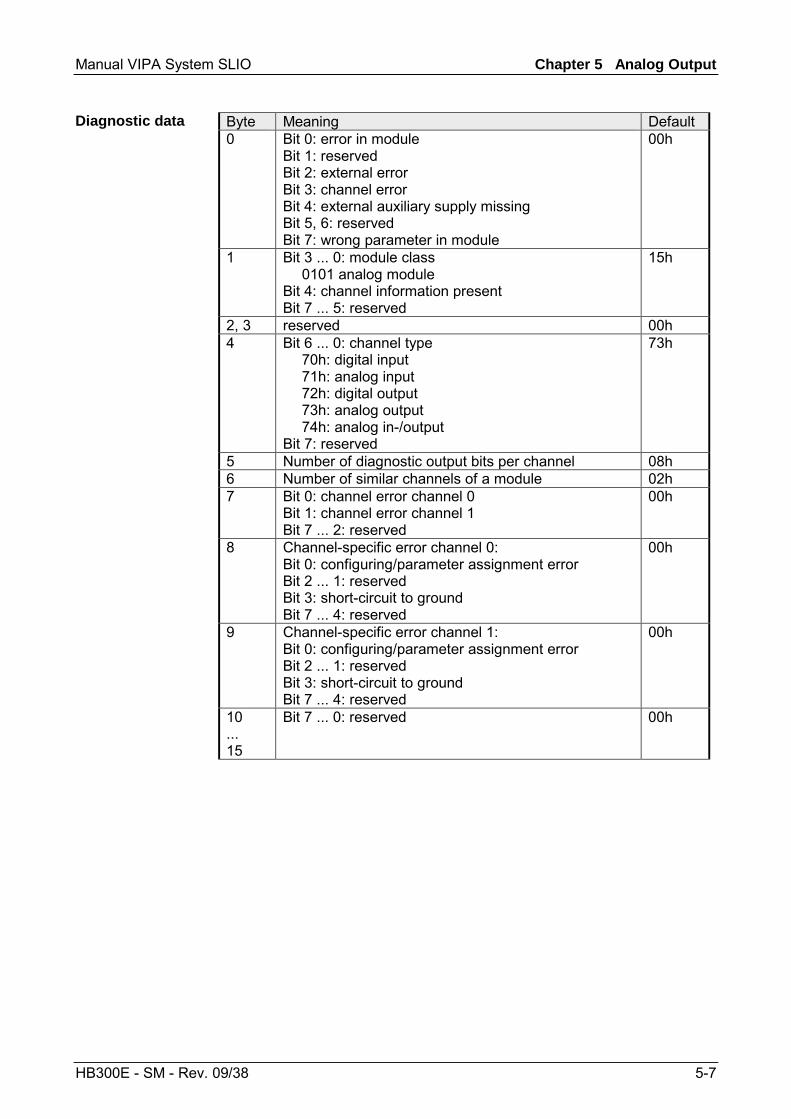
Manual VIPA System SLIO Chapter 5 Analog Output
HB300E - SM - Rev. 09/38 5-7
Byte Meaning Default 0 Bit 0: error in module
Bit 1: reserved Bit 2: external error Bit 3: channel error Bit 4: external auxiliary supply missing Bit 5, 6: reserved Bit 7: wrong parameter in module
00h
1 Bit 3 ... 0: module class 0101 analog module Bit 4: channel information present Bit 7 ... 5: reserved
15h
2, 3 reserved 00h 4 Bit 6 ... 0: channel type
70h: digital input 71h: analog input 72h: digital output 73h: analog output 74h: analog in-/output Bit 7: reserved
73h
5 Number of diagnostic output bits per channel 08h 6 Number of similar channels of a module 02h 7 Bit 0: channel error channel 0
Bit 1: channel error channel 1 Bit 7 ... 2: reserved
00h
8 Channel-specific error channel 0: Bit 0: configuring/parameter assignment error Bit 2 ... 1: reserved Bit 3: short-circuit to ground Bit 7 ... 4: reserved
00h
9 Channel-specific error channel 1: Bit 0: configuring/parameter assignment error Bit 2 ... 1: reserved Bit 3: short-circuit to ground Bit 7 ... 4: reserved
00h
10 ... 15
Bit 7 ... 0: reserved 00h
Diagnostic data
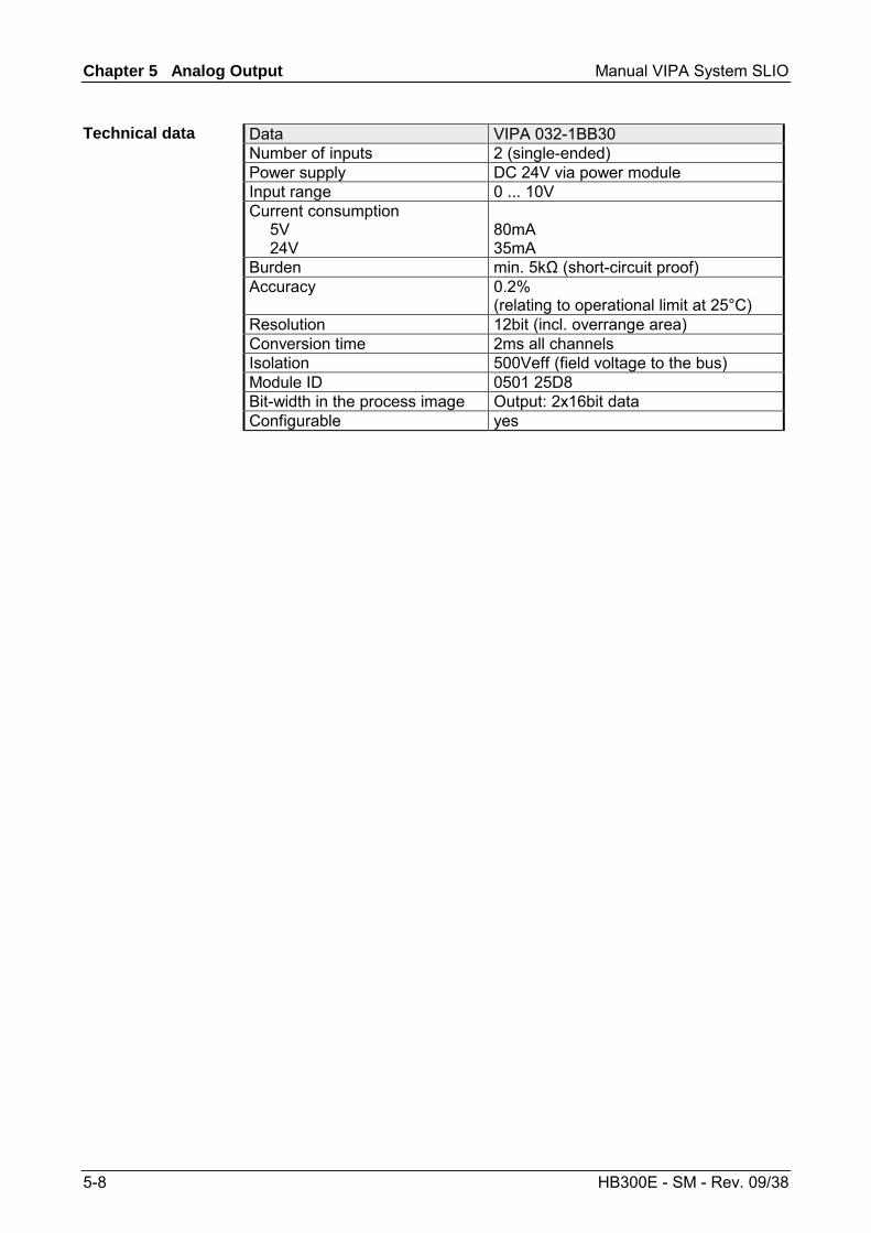
Chapter 5 Analog Output Manual VIPA System SLIO
5-8 HB300E - SM - Rev. 09/38
Data VIPA 032-1BB30 Number of inputs 2 (single-ended) Power supply DC 24V via power module Input range 0 ... 10V Current consumption 5V 24V
80mA 35mA
Burden min. 5kΩ (short-circuit proof) Accuracy 0.2%
(relating to operational limit at 25°C) Resolution 12bit (incl. overrange area) Conversion time 2ms all channels Isolation 500Veff (field voltage to the bus) Module ID 0501 25D8 Bit-width in the process image Output: 2x16bit data Configurable yes
Technical data

Manual VIPA System SLIO Chapter 5 Analog Output
HB300E - SM - Rev. 09/38 5-9
VIPA 032-1BB40 - AO 2x12Bit 0(4)...20mA
The electronic module has 2 outputs with parameterizable functions. The channels of the module are isolated to the backplane bus by means of DC/DC converters.
• 2 analog inputs • Suited for sensors with 0...20mA; 4...20mA • 12bit resolution
1
3
546
78
9
2
[1] [2] [3] [4] [5] [6] [7] [8] [9]
Locking lever terminal module Labeling strip Backplane bus LED status indication DC 24V power section supply Electronic module Terminal module Locking lever electronic module Terminal
LED Color Description RUN green RUN MF MF red Bus communication is OK
Module status is OK Bus communication is OK
Module status reports an error Bus communication is not possible
Module status reports an error Error at bus power supply Error in parameterization
Status indication
RUNMF
AO 0AO 1
AO x red Error channel x - Overload, short-circuit - Error in parameterization - Wire-break
on: off: blinks with 2Hz:
Description
Properties
Structure
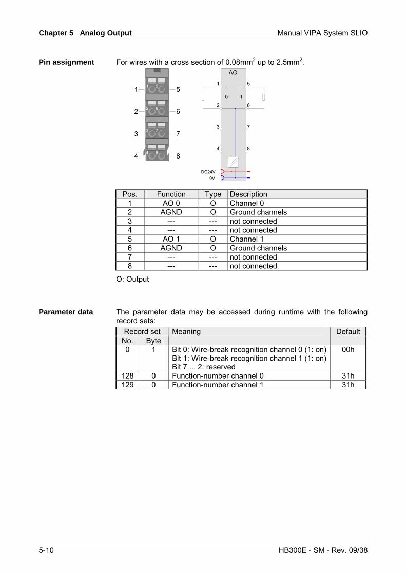
Chapter 5 Analog Output Manual VIPA System SLIO
5-10 HB300E - SM - Rev. 09/38
For wires with a cross section of 0.08mm2 up to 2.5mm2.
2 6
3 7
4 8
1 51
2
3
4
5
6
7
8
DC24V0V
AO
1
2
3
4
5
6
7
8
0 1
Pos. Function Type Description 1 AO 0 O Channel 0 2 AGND O Ground channels 3 --- --- not connected 4 --- --- not connected 5 AO 1 O Channel 1 6 AGND O Ground channels 7 --- --- not connected 8 --- --- not connected
O: Output
The parameter data may be accessed during runtime with the following record sets:
Record set No. Byte
Meaning Default
0 1 Bit 0: Wire-break recognition channel 0 (1: on) Bit 1: Wire-break recognition channel 1 (1: on) Bit 7 ... 2: reserved
00h
128 0 Function-number channel 0 31h 129 0 Function-number channel 1 31h
Pin assignment
Parameter data
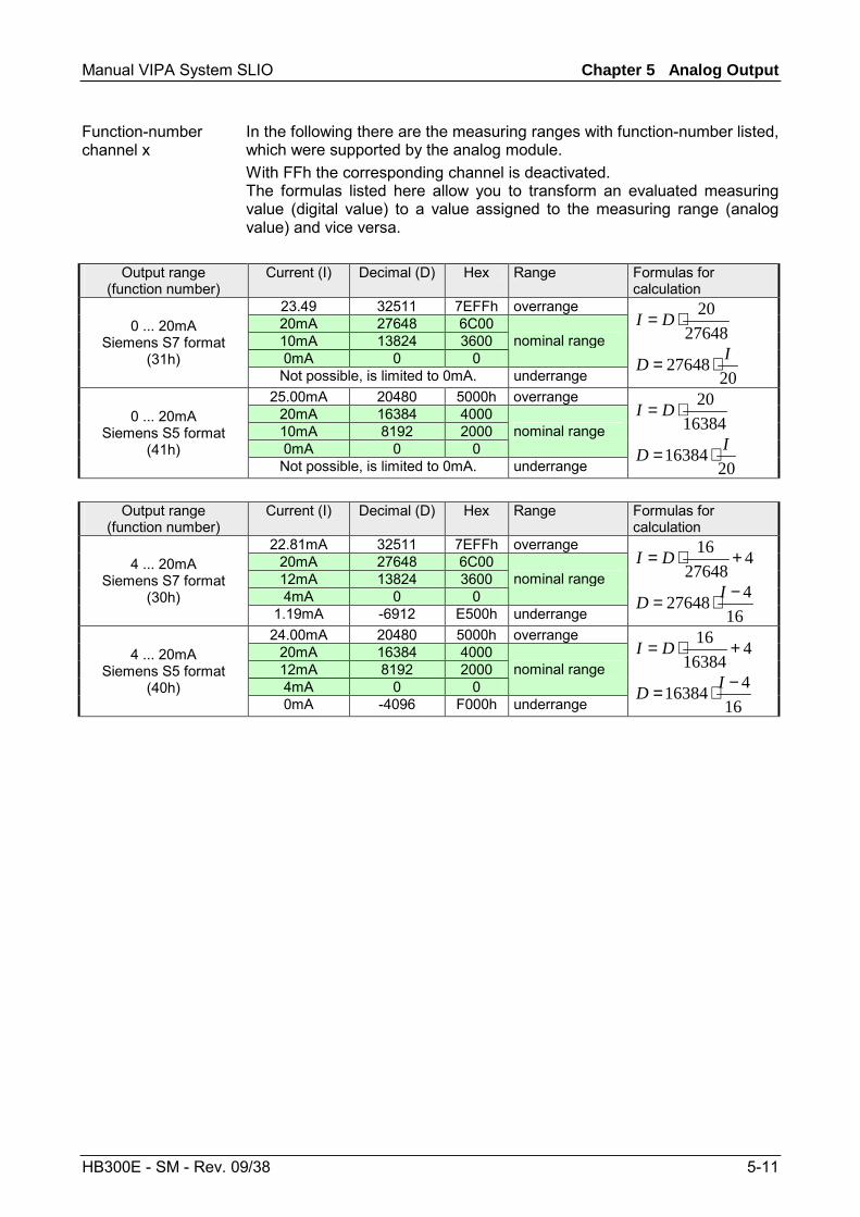
Manual VIPA System SLIO Chapter 5 Analog Output
HB300E - SM - Rev. 09/38 5-11
In the following there are the measuring ranges with function-number listed, which were supported by the analog module. With FFh the corresponding channel is deactivated. The formulas listed here allow you to transform an evaluated measuring value (digital value) to a value assigned to the measuring range (analog value) and vice versa.
Output range (function number)
Current (I) Decimal (D) Hex Range Formulas for calculation
23.49 32511 7EFFh overrange 20mA 27648 6C00 10mA 13824 3600 0mA 0 0
nominal range 0 ... 20mA
Siemens S7 format (31h)
Not possible, is limited to 0mA. underrange
2764820⋅= DI
2027648 ID ⋅=
25.00mA 20480 5000h overrange 20mA 16384 4000 10mA 8192 2000 0mA 0 0
nominal range 0 ... 20mA
Siemens S5 format (41h)
Not possible, is limited to 0mA. underrange
1638420⋅= DI
2016384 ID ⋅=
Output range
(function number) Current (I) Decimal (D) Hex Range Formulas for
calculation 22.81mA 32511 7EFFh overrange
20mA 27648 6C00 12mA 13824 3600 4mA 0 0
nominal range 4 ... 20mA
Siemens S7 format (30h)
1.19mA -6912 E500h underrange
427648
16 +⋅= DI
16427648 −⋅= ID
24.00mA 20480 5000h overrange 20mA 16384 4000 12mA 8192 2000 4mA 0 0
nominal range 4 ... 20mA
Siemens S5 format (40h)
0mA -4096 F000h underrange
416384
16 +⋅= DI
16416384 −⋅= ID
Function-number channel x
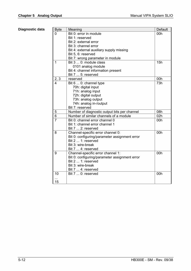
Chapter 5 Analog Output Manual VIPA System SLIO
5-12 HB300E - SM - Rev. 09/38
Byte Meaning Default 0 Bit 0: error in module
Bit 1: reserved Bit 2: external error Bit 3: channel error Bit 4: external auxiliary supply missing Bit 5, 6: reserved Bit 7: wrong parameter in module
00h
1 Bit 3 ... 0: module class 0101 analog module Bit 4: channel information present Bit 7 ... 5: reserved
15h
2, 3 reserved 00h 4 Bit 6 ... 0: channel type
70h: digital input 71h: analog input 72h: digital output 73h: analog output 74h: analog in-/output Bit 7: reserved
73h
5 Number of diagnostic output bits per channel 08h 6 Number of similar channels of a module 02h 7 Bit 0: channel error channel 0
Bit 1: channel error channel 1 Bit 7 ... 2: reserved
00h
8 Channel-specific error channel 0: Bit 0: configuring/parameter assignment error Bit 2 ... 1: reserved Bit 3: wire-break Bit 7 ... 4: reserved
00h
9 Channel-specific error channel 1: Bit 0: configuring/parameter assignment error Bit 2 ... 1: reserved Bit 3: wire-break Bit 7 ... 4: reserved
00h
10 ... 15
Bit 7 ... 0: reserved 00h
Diagnostic data
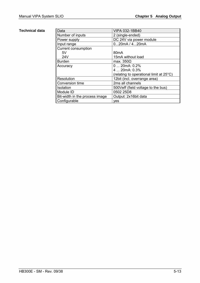
Manual VIPA System SLIO Chapter 5 Analog Output
HB300E - SM - Rev. 09/38 5-13
Data VIPA 032-1BB40 Number of inputs 2 (single-ended) Power supply DC 24V via power module Input range 0...20mA / 4...20mA Current consumption 5V 24V
80mA 15mA without load
Burden max. 350Ω Accuracy 0 ... 20mA: 0.2%
4 ... 20mA: 0.3% (relating to operational limit at 25°C)
Resolution 12bit (incl. overrange area) Conversion time 2ms all channels Isolation 500Veff (field voltage to the bus) Module ID 0502 25D8 Bit-width in the process image Output: 2x16bit data Configurable yes
Technical data

Chapter 5 Analog Output Manual VIPA System SLIO
5-14 HB300E - SM - Rev. 09/38
VIPA 032-1BD30 - AO 4x12Bit 0...10V
The electronic module has 4 outputs with parameterizable functions. The channels of the module are isolated to the backplane bus by means of DC/DC converters.
• 4 analog outputs • Suited for sensors with 0 ... 10V • 12bit resolution
1
3
546
78
9
2
[1] [2] [3] [4] [5] [6] [7] [8] [9]
Locking lever terminal module Labeling strip Backplane bus LED status indication DC 24V power section supply Electronic module Terminal module Locking lever electronic module Terminal
LED Color Description RUN green RUN MF MF red Bus communication is OK
Module status is OK Bus communication is OK
Module status reports an error Bus communication is not possible
Module status reports an error Error at bus power supply Error in parameterization
Status indication
RUNMF
AO 0AO 1AO 2AO 3
AO x red Error channel x - Overload, short-circuit - Error in parameterization
on: off: blinks with 2Hz:
Description
Properties
Structure
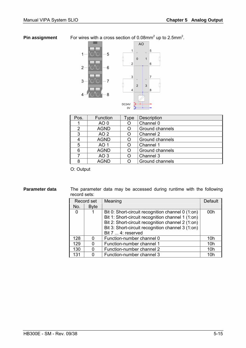
Manual VIPA System SLIO Chapter 5 Analog Output
HB300E - SM - Rev. 09/38 5-15
For wires with a cross section of 0.08mm2 up to 2.5mm2.
2 6
3 7
4 8
1 51
2
3
4
5
6
7
8
DC24V0V
AO
1
2
3
4
5
6
7
8
0 1
2 3
Pos. Function Type Description 1 AO 0 O Channel 0 2 AGND O Ground channels 3 AO 2 O Channel 2 4 AGND O Ground channels 5 AO 1 O Channel 1 6 AGND O Ground channels 7 AO 3 O Channel 3 8 AGND O Ground channels
O: Output
The parameter data may be accessed during runtime with the following record sets:
Record set No. Byte
Meaning Default
0 1 Bit 0: Short-circuit recognition channel 0 (1:on) Bit 1: Short-circuit recognition channel 1 (1:on) Bit 2: Short-circuit recognition channel 2 (1:on) Bit 3: Short-circuit recognition channel 3 (1:on) Bit 7 ... 4: reserved
00h
128 0 Function-number channel 0 10h 129 0 Function-number channel 1 10h 130 0 Function-number channel 2 10h 131 0 Function-number channel 3 10h
Pin assignment
Parameter data
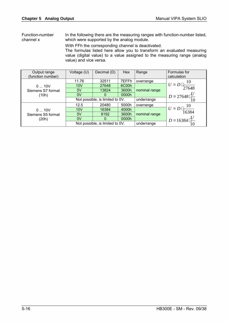
Chapter 5 Analog Output Manual VIPA System SLIO
5-16 HB300E - SM - Rev. 09/38
In the following there are the measuring ranges with function-number listed, which were supported by the analog module. With FFh the corresponding channel is deactivated. The formulas listed here allow you to transform an evaluated measuring value (digital value) to a value assigned to the measuring range (analog value) and vice versa.
Output range (function number)
Voltage (U) Decimal (D) Hex Range Formulas for calculation
11.76 32511 7EFFh overrange 10V 27648 6C00h 5V 13824 3600h 0V 0 0000h
nominal range 0 ... 10V
Siemens S7 format (10h)
Not possible, is limited to 0V. underrange
2764810⋅= DU
1027648 UD ⋅=
12.5 20480 5000h overrange 10V 16384 4000h 5V 8192 3600h 0V 0 0000h
nominal range 0 ... 10V
Siemens S5 format (20h)
Not possible, is limited to 0V. underrange
1638410⋅= DU
1016384 UD ⋅=
Function-number channel x
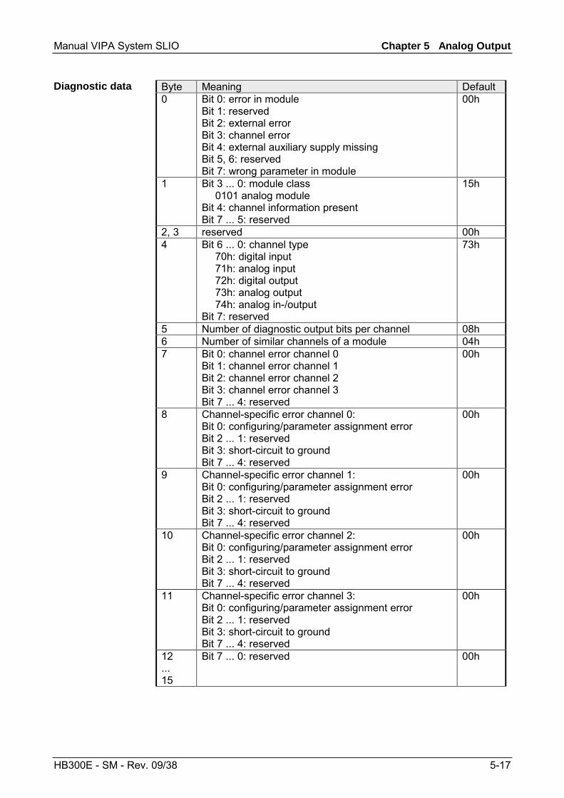
Manual VIPA System SLIO Chapter 5 Analog Output
HB300E - SM - Rev. 09/38 5-17
Byte Meaning Default 0 Bit 0: error in module
Bit 1: reserved Bit 2: external error Bit 3: channel error Bit 4: external auxiliary supply missing Bit 5, 6: reserved Bit 7: wrong parameter in module
00h
1 Bit 3 ... 0: module class 0101 analog module Bit 4: channel information present Bit 7 ... 5: reserved
15h
2, 3 reserved 00h 4 Bit 6 ... 0: channel type
70h: digital input 71h: analog input 72h: digital output 73h: analog output 74h: analog in-/output Bit 7: reserved
73h
5 Number of diagnostic output bits per channel 08h 6 Number of similar channels of a module 04h 7 Bit 0: channel error channel 0
Bit 1: channel error channel 1 Bit 2: channel error channel 2 Bit 3: channel error channel 3 Bit 7 ... 4: reserved
00h
8 Channel-specific error channel 0: Bit 0: configuring/parameter assignment error Bit 2 ... 1: reserved Bit 3: short-circuit to ground Bit 7 ... 4: reserved
00h
9 Channel-specific error channel 1: Bit 0: configuring/parameter assignment error Bit 2 ... 1: reserved Bit 3: short-circuit to ground Bit 7 ... 4: reserved
00h
10 Channel-specific error channel 2: Bit 0: configuring/parameter assignment error Bit 2 ... 1: reserved Bit 3: short-circuit to ground Bit 7 ... 4: reserved
00h
11 Channel-specific error channel 3: Bit 0: configuring/parameter assignment error Bit 2 ... 1: reserved Bit 3: short-circuit to ground Bit 7 ... 4: reserved
00h
12 ... 15
Bit 7 ... 0: reserved 00h
Diagnostic data
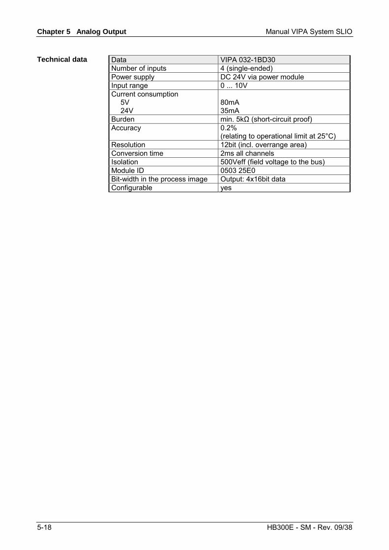
Chapter 5 Analog Output Manual VIPA System SLIO
5-18 HB300E - SM - Rev. 09/38
Data VIPA 032-1BD30 Number of inputs 4 (single-ended) Power supply DC 24V via power module Input range 0 ... 10V Current consumption 5V 24V
80mA 35mA
Burden min. 5kΩ (short-circuit proof) Accuracy 0.2%
(relating to operational limit at 25°C) Resolution 12bit (incl. overrange area) Conversion time 2ms all channels Isolation 500Veff (field voltage to the bus) Module ID 0503 25E0 Bit-width in the process image Output: 4x16bit data Configurable yes
Technical data

Manual VIPA System SLIO Chapter 5 Analog Output
HB300E - SM - Rev. 09/38 5-19
VIPA 032-1BD40 - AO 4x12Bit 0(4)...20mA
The electronic module has 4 outputs with parameterizable functions. The channels of the module are isolated to the backplane bus by means of DC/DC converters.
• 4 analog inputs • Suited for sensors with 0...20mA; 4...20mA • 12bit resolution
1
3
546
78
9
2
[1] [2] [3] [4] [5] [6] [7] [8] [9]
Locking lever terminal module Labeling strip Backplane bus LED status indication DC 24V power section supply Electronic module Terminal module Locking lever electronic module Terminal
LED Color Description RUN green RUN MF MF red Bus communication is OK
Module status is OK Bus communication is OK
Module status reports an error Bus communication is not possible
Module status reports an error Error at bus power supply Error in parameterization
(if parameterizable)
Status indication
RUNMF
AO 0AO 1AO 2AO 3
AO x red Error channel x - Overload, short-circuit - Error in parameterization - Wire-break
on: off: blinks with 2Hz:
Description
Properties
Structure
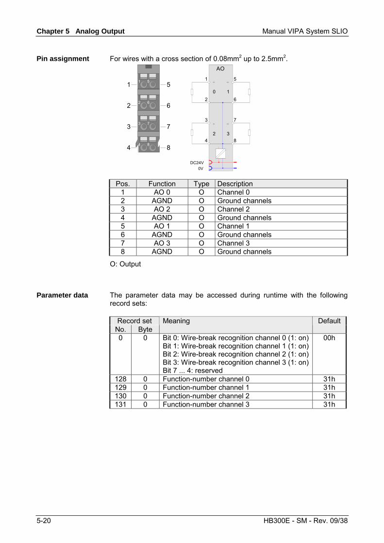
Chapter 5 Analog Output Manual VIPA System SLIO
5-20 HB300E - SM - Rev. 09/38
For wires with a cross section of 0.08mm2 up to 2.5mm2.
2 6
3 7
4 8
1 51
2
3
4
5
6
7
8
DC24V0V
AO
1
2
3
4
5
6
7
8
0 1
2 3
Pos. Function Type Description 1 AO 0 O Channel 0 2 AGND O Ground channels 3 AO 2 O Channel 2 4 AGND O Ground channels 5 AO 1 O Channel 1 6 AGND O Ground channels 7 AO 3 O Channel 3 8 AGND O Ground channels
O: Output
The parameter data may be accessed during runtime with the following record sets:
Record set No. Byte
Meaning Default
0 0 Bit 0: Wire-break recognition channel 0 (1: on) Bit 1: Wire-break recognition channel 1 (1: on) Bit 2: Wire-break recognition channel 2 (1: on) Bit 3: Wire-break recognition channel 3 (1: on) Bit 7 ... 4: reserved
00h
128 0 Function-number channel 0 31h 129 0 Function-number channel 1 31h 130 0 Function-number channel 2 31h 131 0 Function-number channel 3 31h
Pin assignment
Parameter data
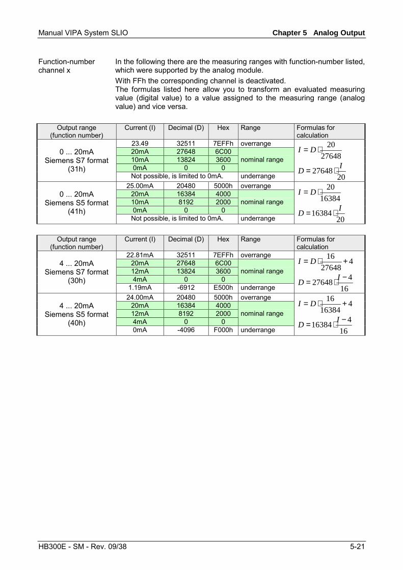
Manual VIPA System SLIO Chapter 5 Analog Output
HB300E - SM - Rev. 09/38 5-21
In the following there are the measuring ranges with function-number listed, which were supported by the analog module. With FFh the corresponding channel is deactivated. The formulas listed here allow you to transform an evaluated measuring value (digital value) to a value assigned to the measuring range (analog value) and vice versa.
Output range (function number)
Current (I) Decimal (D) Hex Range Formulas for calculation
23.49 32511 7EFFh overrange 20mA 27648 6C00 10mA 13824 3600 0mA 0 0
nominal range 0 ... 20mA
Siemens S7 format (31h)
Not possible, is limited to 0mA. underrange
2764820⋅= DI
2027648 ID ⋅=
25.00mA 20480 5000h overrange 20mA 16384 4000 10mA 8192 2000 0mA 0 0
nominal range 0 ... 20mA
Siemens S5 format (41h)
Not possible, is limited to 0mA. underrange
1638420⋅= DI
2016384 ID ⋅=
Output range
(function number) Current (I) Decimal (D) Hex Range Formulas for
calculation 22.81mA 32511 7EFFh overrange
20mA 27648 6C00 12mA 13824 3600 4mA 0 0
nominal range 4 ... 20mA
Siemens S7 format (30h)
1.19mA -6912 E500h underrange
427648
16 +⋅= DI
16427648 −⋅= ID
24.00mA 20480 5000h overrange 20mA 16384 4000 12mA 8192 2000 4mA 0 0
nominal range 4 ... 20mA
Siemens S5 format (40h)
0mA -4096 F000h underrange
416384
16 +⋅= DI
16416384 −⋅= ID
Function-number channel x
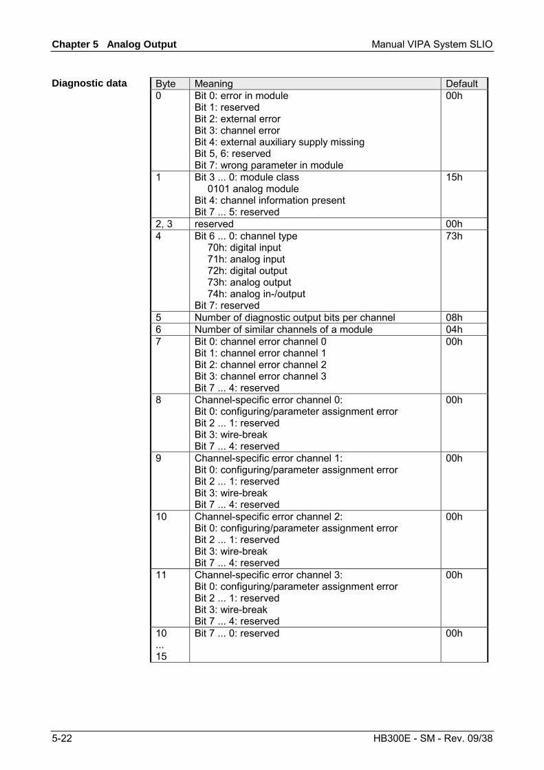
Chapter 5 Analog Output Manual VIPA System SLIO
5-22 HB300E - SM - Rev. 09/38
Byte Meaning Default 0 Bit 0: error in module
Bit 1: reserved Bit 2: external error Bit 3: channel error Bit 4: external auxiliary supply missing Bit 5, 6: reserved Bit 7: wrong parameter in module
00h
1 Bit 3 ... 0: module class 0101 analog module Bit 4: channel information present Bit 7 ... 5: reserved
15h
2, 3 reserved 00h 4 Bit 6 ... 0: channel type
70h: digital input 71h: analog input 72h: digital output 73h: analog output 74h: analog in-/output Bit 7: reserved
73h
5 Number of diagnostic output bits per channel 08h 6 Number of similar channels of a module 04h 7 Bit 0: channel error channel 0
Bit 1: channel error channel 1 Bit 2: channel error channel 2 Bit 3: channel error channel 3 Bit 7 ... 4: reserved
00h
8 Channel-specific error channel 0: Bit 0: configuring/parameter assignment error Bit 2 ... 1: reserved Bit 3: wire-break Bit 7 ... 4: reserved
00h
9 Channel-specific error channel 1: Bit 0: configuring/parameter assignment error Bit 2 ... 1: reserved Bit 3: wire-break Bit 7 ... 4: reserved
00h
10 Channel-specific error channel 2: Bit 0: configuring/parameter assignment error Bit 2 ... 1: reserved Bit 3: wire-break Bit 7 ... 4: reserved
00h
11 Channel-specific error channel 3: Bit 0: configuring/parameter assignment error Bit 2 ... 1: reserved Bit 3: wire-break Bit 7 ... 4: reserved
00h
10 ... 15
Bit 7 ... 0: reserved 00h
Diagnostic data
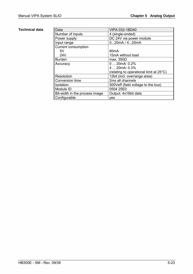
Manual VIPA System SLIO Chapter 5 Analog Output
HB300E - SM - Rev. 09/38 5-23
Data VIPA 032-1BD40 Number of inputs 4 (single-ended) Power supply DC 24V via power module Input range 0...20mA / 4...20mA Current consumption 5V 24V
80mA 15mA without load
Burden max. 350Ω Accuracy 0 ... 20mA: 0.2%
4 ... 20mA: 0.3% (relating to operational limit at 25°C)
Resolution 12bit (incl. overrange area) Conversion time 2ms all channels Isolation 500Veff (field voltage to the bus) Module ID 0504 25E0 Bit-width in the process image Output: 4x16bit data Configurable yes
Technical data
Chapter 5 Analog Output Manual VIPA System SLIO
5-24 HB300E - SM - Rev. 09/38
Recommended