Version 3.2 March 2013 CQIE MOP Part D
NCI Centers of Quantitative Imaging Excellence
MANUAL OF PROCEDURES
PART D
PET‐PET/CT TECHNICAL PROCEDURES
American College Radiology Imaging Network CQIE Manual of Procedures
Version 3.2 March 2013 Part D: 1 of 9
PART D
PET‐PET/CT TECHNICAL PROCEDURES
1. CQIE PET‐PET/CT QUALIFICATION
1.1 Introduction
The purpose of this chapter is to provide detailed technical information regarding the PET and PET/CT phantom scanning and QC activities required for CQIE qualification. For a full description of the qualification program refer to Part A of the CQIE Manual of Procedures (MOP). The PET procedures and guidelines outlined in this document apply to all scanners to be qualified. Though qualification of only one PET or PET/CT scanner is required, sites are urged to qualify multiple scanners. With the purpose of advancing standardization and harmonization of imaging data in multicenter clinical trials, all scanners to be used for NCI clinical trial imaging should be qualified. As explained in Part A, Section 1.2, of the CQIE MOP, the primary objective of the CQIE program is to establish a resource of ‘trial ready’ sites within the NCI Cancer Centers that are capable of conducting clinical trials in which there is an integral molecular and functional advanced imaging endpoint. In support of this objective, the CQIE program is designed to qualify sites to participate in advanced imaging trials which include static and dynamic PET or PET/CT of the brain and body.
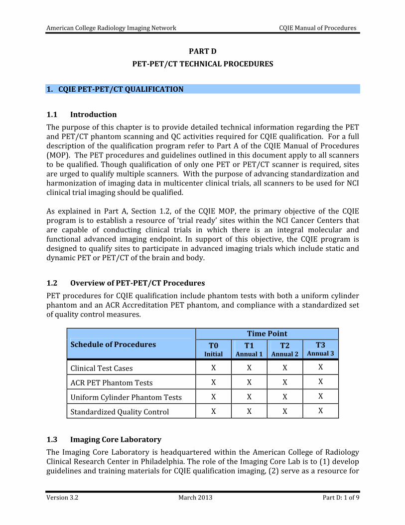
1.2 Overview of PET‐PET/CT Procedures
PET procedures for CQIE qualification include phantom tests with both a uniform cylinder phantom and an ACR Accreditation PET phantom, and compliance with a standardized set of quality control measures.
Schedule of Procedures
Time Point
T0 Initial
T1 Annual 1
T2 Annual 2
T3 Annual 3
Clinical Test Cases X X X X
ACR PET Phantom Tests X X X X
Uniform Cylinder Phantom Tests X X X X
Standardized Quality Control X X X X
1.3 Imaging Core Laboratory
The Imaging Core Laboratory is headquartered within the American College of Radiology Clinical Research Center in Philadelphia. The role of the Imaging Core Lab is to (1) develop guidelines and training materials for CQIE qualification imaging, (2) serve as a resource for
American College Radiology Imaging Network CQIE Manual of Procedures
Version 3.2 March 2013 Part D: 2 of 9
site staff regarding technical and procedural issues associated with the qualification requirements and quantitative imaging, (3) collect and archive qualification imaging data, and (4) manage the qualitative and quantitative review of the qualification imaging data. Should you have any questions or require additional information please consult the CQIE web site at http://www.acrin.org/NCI‐CQIE.aspx or a member of the ACRIN CQIE project team.
PROJECT MANAGEMENT IMAGING
CQIE‐[email protected] CQIE‐MR‐[email protected]
Telephone: 215‐940‐8921 CQIE‐[email protected]
Fax: 215‐717‐0860
ACRIN hours of operation are 8:30 – 5:00 ET
American College Radiology Imaging Network CQIE Manual of Procedures
Version 3.2 March 2013 Part D: 3 of 9
2. QUALIFICATION IMAGING
2.1 Clinical Test Cases
For initial and annual qualification assessments, sites are required to submit two test cases for the Brain and Body FOVs. The test cases can be any FDG study with or without abnormal findings. The test cases should be acquired and reconstructed according to the site’s standard protocols and be acquired within one month of the submission time point (initial qualification and annual requalification). For each test case, sites need to submit the attenuation‐corrected (AC) PET, non‐attenuation‐corrected (NAC) PET and CT image sets to the ACRIN Imaging Core Lab. All images must be in DICOM format. For initial qualification, the image sets should be submitted with or soon after submission of the Site Assessment Form and must be submitted prior to the ACRIN site visit. For annual requalification, the image sets should be submitted with the annual phantom testing data. Refer to Section 4 of this document for details regarding data submission.
The Test Cases will be qualitatively reviewed for overall technical image quality. This assessment will include a comparison of the technical parameters in the DICOM header with those recorded in Part D of the Site Assessment Form, an analysis of the quality of the PET and CT fusion, and an overall evaluation for anything that may hinder a reviewer’s ability to interpret the study.
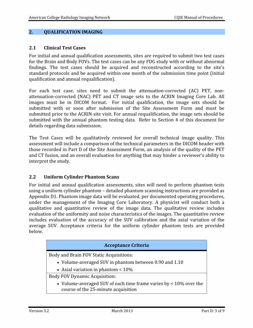
2.2 Uniform Cylinder Phantom Scans
For initial and annual qualification assessments, sites will need to perform phantom tests using a uniform cylinder phantom – detailed phantom scanning instructions are provided as Appendix D1. Phantom image data will be evaluated, per documented operating procedures, under the management of the Imaging Core Laboratory. A physicist will conduct both a qualitative and quantitative review of the image data. The qualitative review includes evaluation of the uniformity and noise characteristics of the images. The quantitative review includes evaluation of the accuracy of the SUV calibration and the axial variation of the average SUV. Acceptance criteria for the uniform cylinder phantom tests are provided below.
Acceptance Criteria
Body and Brain FOV Static Acquisitions:
Volume‐averaged SUV in phantom between 0.90 and 1.10
Axial variation in phantom < 10%
Body FOV Dynamic Acquisition:
Volume‐averaged SUV of each time frame varies by < 10% over the course of the 25‐minute acquisition
American College Radiology Imaging Network CQIE Manual of Procedures
Version 3.2 March 2013 Part D: 4 of 9
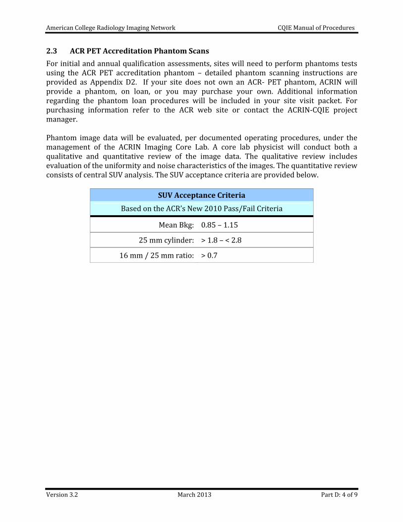
2.3 ACR PET Accreditation Phantom Scans
For initial and annual qualification assessments, sites will need to perform phantoms tests using the ACR PET accreditation phantom – detailed phantom scanning instructions are provided as Appendix D2. If your site does not own an ACR‐ PET phantom, ACRIN will provide a phantom, on loan, or you may purchase your own. Additional information regarding the phantom loan procedures will be included in your site visit packet. For purchasing information refer to the ACR web site or contact the ACRIN‐CQIE project manager. Phantom image data will be evaluated, per documented operating procedures, under the management of the ACRIN Imaging Core Lab. A core lab physicist will conduct both a qualitative and quantitative review of the image data. The qualitative review includes evaluation of the uniformity and noise characteristics of the images. The quantitative review consists of central SUV analysis. The SUV acceptance criteria are provided below.
SUV Acceptance Criteria
Based on the ACR’s New 2010 Pass/Fail Criteria
Mean Bkg: 0.85 – 1.15
25 mm cylinder: > 1.8 – < 2.8
16 mm / 25 mm ratio: > 0.7
American College Radiology Imaging Network CQIE Manual of Procedures
Version 3.2 March 2013 Part D: 5 of 9
3. STANDARDIZED QUALITY CONTROL
3.1 Routine Quality Control
Quality control is an important function of image quality and patient safety and takes on even greater importance in multicenter quantitative imaging trials. The benefits of quality control include: verification of the operational integrity of the systems, consistent and high image quality, decreased chance of artifacts, early identification of potential problems, and consistent quantitative accuracy. As such, quality control of imaging equipment is fundamental to the goal of image standardization in imaging and therapy trials. In line with recommendations of the American College of Radiology, all CQIE sites are required to have a documented quality assurance program monitored by a medical physicist (or other qualified individual). For additional guidance, please reference ACR Technical Standard for Medical Nuclear Physics Performance Monitoring of PET Imaging Equipment, ACR Technical Standard for Diagnostic Procedures Using Radiopharmaceuticals, ACR Technical Standard for Medical Nuclear Physics Performance Monitoring of PET Imaging/CT Imaging Equipment, and ACR Practice Guideline for Performing FDG‐PET/CT in Oncology.
3.1.1 Acceptance Testing
The aim of acceptance testing is to verify that the equipment performs according to its specifications and clinical purpose. Acceptance testing should be performed according to manufacturer recommendations upon installation of imaging equipment and after major upgrades, before clinical use.
3.1.2 Routine Quality Control Testing
Routine performance tests and preventive maintenance are to be conducted according to manufacturer recommendations and include regular testing procedures to insure proper operation on a daily basis. Federal standards require PET and PET/CT manufacturers to provide quality assurance testing instructions, recommended testing frequency, an appropriate QC phantom and acceptable variations in parameter measurements. For SUV measurements, assessment should include a comparison against a dose calibrator to ensure accuracy; that is, a comparison of the absolute activity measured versus the measured activity injected. If any QC parameter being monitored falls outside of the control limits, corrective action should be taken.
3.2 CQIE Standardized Quality Control
To address the need of imaging standardization in multicenter and/or quantitative imaging trials, CQIE sites are expected to comply with the quality control testing (and frequency) identified in 3.2.1 below. These tests may already be part of your existing QC program. If not, these tests are to be incorporated into your continuous quality control activities. Note that the standardized CQIE QC measures do not replace any QC measures required by law, accreditations, or those recommended by the manufacturer. Rather these QC measures were adopted for the CQIE program based on published recommendations by organizations and researchers involved in quantitative imaging and are intended to serve as a minimum
American College Radiology Imaging Network CQIE Manual of Procedures
Version 3.2 March 2013 Part D: 6 of 9
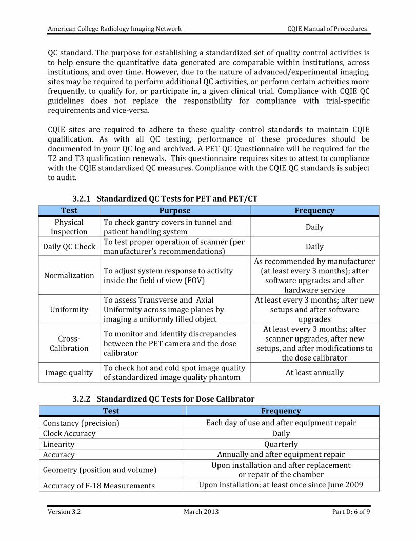
QC standard. The purpose for establishing a standardized set of quality control activities is to help ensure the quantitative data generated are comparable within institutions, across institutions, and over time. However, due to the nature of advanced/experimental imaging, sites may be required to perform additional QC activities, or perform certain activities more frequently, to qualify for, or participate in, a given clinical trial. Compliance with CQIE QC guidelines does not replace the responsibility for compliance with trial‐specific requirements and vice‐versa. CQIE sites are required to adhere to these quality control standards to maintain CQIE qualification. As with all QC testing, performance of these procedures should be documented in your QC log and archived. A PET QC Questionnaire will be required for the T2 and T3 qualification renewals. This questionnaire requires sites to attest to compliance with the CQIE standardized QC measures. Compliance with the CQIE QC standards is subject to audit.
3.2.1 Standardized QC Tests for PET and PET/CT
Test Purpose Frequency
Physical Inspection
To check gantry covers in tunnel and patient handling system
Daily
Daily QC Check To test proper operation of scanner (per manufacturer’s recommendations)
Daily
Normalization To adjust system response to activity inside the field of view (FOV)
As recommended by manufacturer (at least every 3 months); after software upgrades and after
hardware service
Uniformity To assess Transverse and Axial Uniformity across image planes by imaging a uniformly filled object
At least every 3 months; after newsetups and after software
upgrades
Cross‐Calibration
To monitor and identify discrepancies between the PET camera and the dose calibrator
At least every 3 months; after scanner upgrades, after new
setups, and after modifications to the dose calibrator
Image quality To check hot and cold spot image quality of standardized image quality phantom
At least annually
3.2.2 Standardized QC Tests for Dose Calibrator
Test Frequency
Constancy (precision) Each day of use and after equipment repair
Clock Accuracy Daily
Linearity Quarterly
Accuracy Annually and after equipment repair
Geometry (position and volume) Upon installation and after replacement
or repair of the chamber
Accuracy of F‐18 Measurements Upon installation; at least once since June 2009
American College Radiology Imaging Network CQIE Manual of Procedures
Version 3.2 March 2013 Part D: 7 of 9
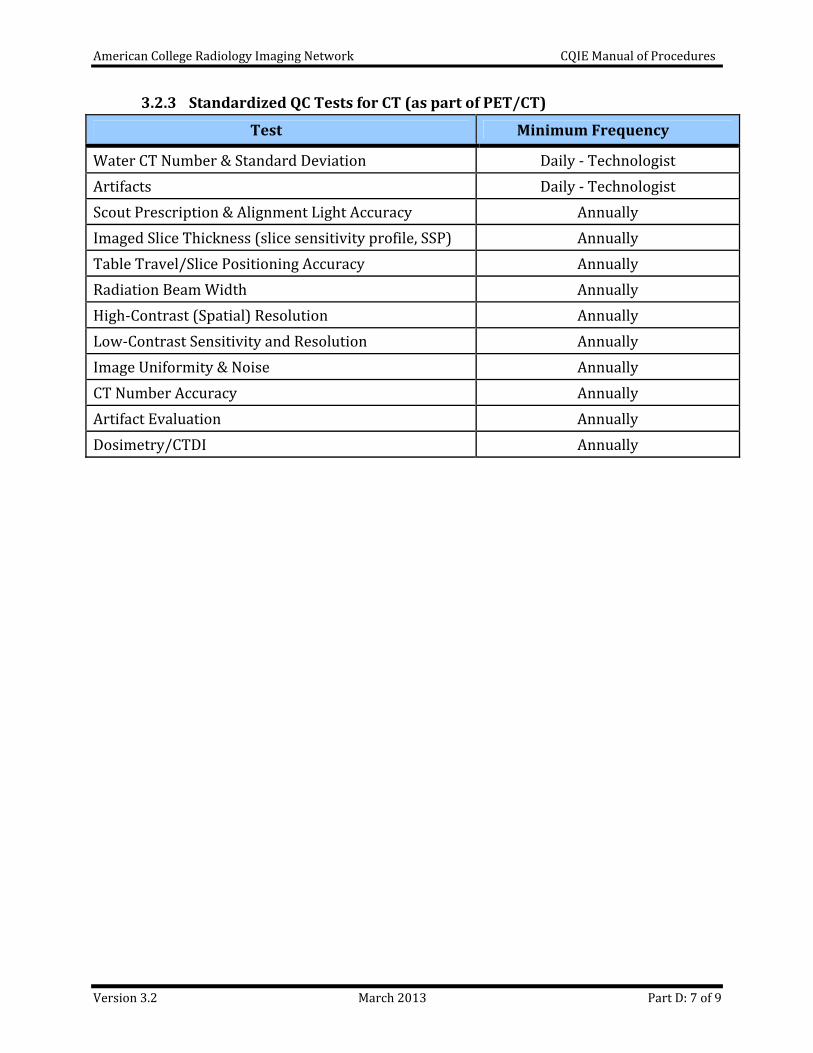
3.2.3 Standardized QC Tests for CT (as part of PET/CT)
Test Minimum Frequency
Water CT Number & Standard Deviation Daily ‐ Technologist
Artifacts Daily ‐ Technologist
Scout Prescription & Alignment Light Accuracy Annually
Imaged Slice Thickness (slice sensitivity profile, SSP) Annually
Table Travel/Slice Positioning Accuracy Annually
Radiation Beam Width Annually
High‐Contrast (Spatial) Resolution Annually
Low‐Contrast Sensitivity and Resolution Annually
Image Uniformity & Noise Annually
CT Number Accuracy Annually
Artifact Evaluation Annually
Dosimetry/CTDI Annually
American College Radiology Imaging Network CQIE Manual of Procedures
Version 3.2 March 2013 Part D: 8 of 9
4. DATA SUBMISSION
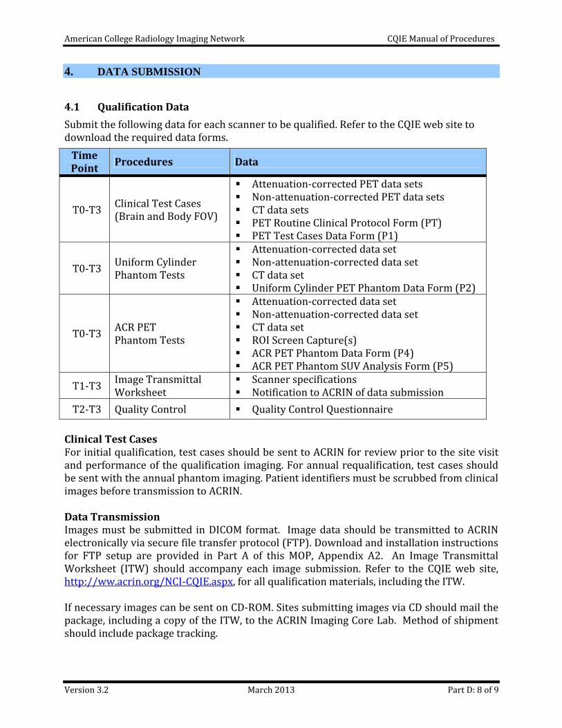
4.1 Qualification Data
Submit the following data for each scanner to be qualified. Refer to the CQIE web site to download the required data forms.
Time Point
Procedures Data
T0‐T3 Clinical Test Cases (Brain and Body FOV)
Attenuation‐corrected PET data sets Non‐attenuation‐corrected PET data sets CT data sets PET Routine Clinical Protocol Form (PT) PET Test Cases Data Form (P1)
T0‐T3 Uniform Cylinder Phantom Tests
Attenuation‐corrected data set Non‐attenuation‐corrected data set CT data set Uniform Cylinder PET Phantom Data Form (P2)
T0‐T3 ACR PET Phantom Tests
Attenuation‐corrected data set Non‐attenuation‐corrected data set CT data set ROI Screen Capture(s) ACR PET Phantom Data Form (P4) ACR PET Phantom SUV Analysis Form (P5)
T1‐T3 Image Transmittal Worksheet
Scanner specifications Notification to ACRIN of data submission
T2‐T3 Quality Control Quality Control Questionnaire
Clinical Test Cases For initial qualification, test cases should be sent to ACRIN for review prior to the site visit and performance of the qualification imaging. For annual requalification, test cases should be sent with the annual phantom imaging. Patient identifiers must be scrubbed from clinical images before transmission to ACRIN. Data Transmission Images must be submitted in DICOM format. Image data should be transmitted to ACRIN electronically via secure file transfer protocol (FTP). Download and installation instructions for FTP setup are provided in Part A of this MOP, Appendix A2. An Image Transmittal Worksheet (ITW) should accompany each image submission. Refer to the CQIE web site, http://ww.acrin.org/NCI‐CQIE.aspx, for all qualification materials, including the ITW. If necessary images can be sent on CD‐ROM. Sites submitting images via CD should mail the package, including a copy of the ITW, to the ACRIN Imaging Core Lab. Method of shipment should include package tracking.
American College Radiology Imaging Network CQIE Manual of Procedures
Version 3.2 March 2013 Part D: 9 of 9
5. References
European Association of Nuclear Medicine Physics Committee. Routine quality control recommendations for nuclear medicine instrumentation. Eur J Nucl Med Imaging. 2010; 37:662‐671.
Boellard R, O’Doherty MJ, Weber W, et al. FDG PET and PET/CT: EANM procedure guidelines for tumor PET imaging: version 1.0. Eur J Nucl Med Mol Imaging. 2009
Boellard R. Standards for PET Image Acquisition and Quantitative Data Analysis. J Nucl Med. 2009; 50:11S‐20S.
American Association of Physicists in Medicine. Quality control in diagnostic radiology. AAPM Report No. 74, July 2002.
American College of Radiology. ACR Technical standard for medical nuclear physics performance monitoring of PET‐CT imaging equipment, 2008.
American College of Radiology. ACR Technical standard for medical nuclear physics performance monitoring of PET imaging equipment, 2006.
American College of Radiology. ACR Technical standard for diagnostic procedures using radiopharmaceuticals, 2006.
CQIE Appendix D1
PET PHANTOM TEST INSTRUCTIONS: UNIFORM CYLINDER PET PHANTOM
Version 3.2 March 2013 1 of 3
This document provides detailed instructions for performing CQIE phantom tests with the uniform cylinder PET phantom.
1. Uniform Cylinder Phantom
The uniform cylinder can be any fill‐able, cylindrical phantom that does not have any internal structure; the phantom should have an internal diameter of 18 cm – 22 cm and a length that is greater than the axial FOV of the scanner. On most systems, the ACR PET phantom can be used for the uniform phantom scans as long as the cold rods and cold spheres are removed and the “flat” lid is used, instead of the lid with the cylinders attached. However, manufacturers typically supply all PET scanners, at the time of installation, with a uniform cylinder that is used for routine QA and calibrations. The uniform cylinder will be filled with a precise amount of radioactivity and scanned using standard acquisition and reconstruction protocols. There will be 3 sequential scans: (1) a two‐bed‐position Body FOV scan using the settings for a 70 kg (~24 BMI) patient; (2) a one‐bed‐position 10 or 20 minute Brain FOV scan; and (3) a one‐bed‐position dynamic Body FOV scan using a pre‐defined acquisition protocol.
2. Phantom Test Preparation
Please read the following instructions in full before preparing and scanning the phantom.
Required Materials
1 ‐ Uniform Cylinder phantom
1 ‐ 60 mL syringe
1 ‐ tuberculin syringe
Clock or Timer
CQIE Uniform Cylinder PET Phantom Data Form
CQIE Uniform Cylinder SUV Analysis Form
Dose: either FDG or F‐18 fluoride are acceptable
Phantom Filling Procedure
Fill the phantom completely with water a few hours before scanning to allow for air bubbles to collect at the top of the phantom.
1. When ready to scan the phantom, ensure that the phantom is completely full, adding additional water with a syringe if necessary, to minimize any air bubble.
2. Using a 60 mL syringe, withdraw ~50 mL of water from the phantom to create a large air space to allow for better mixing.
3. Inject a known amount of FDG or F‐18 fluoride; the activity injected should be within the range of 135 – 165 nCi/mL.
CQIE Appendix D1
PET PHANTOM TEST INSTRUCTIONS: UNIFORM CYLINDER PET PHANTOM
Version 3.2 March 2013 2 of 3
GE: 5,640 mL phantom, inject 0.76 – 0.93 mCi
Siemens: 6,283 mL phantom, inject 1.0‐1.5 mCi
Philips: 9,293 mL phantom, inject 1.25 – 1.53mCi
4. Record the activity in the syringe before injection on the Uniform Cylinder PET Phantom Data Form.
5. Repeatedly flush the syringe to ensure that there is little residual activity in the syringe.
6. Thoroughly combine the mixture by repeatedly inverting the phantom.
7. Inject the water that was removed from the phantom in step 2 until the phantom is completely full.
8. Measure the syringe in the dose calibrator and record the residual activity on the Uniform Cylinder PET Phantom Data Form.
9. The phantom scan should begin immediately after filling.
3. Data Acquisition and Reconstruction When setting up the scans, enter your institution name in the patient name field (see example below). Patient Name: CQIE Name of Your Cancer Center (ex. ACRIN Cancer Center)
Positioning the Phantom
Place the phantom on its side on the scanner table. Some sheets may be used under the phantom to prevent the phantom from rolling and to assist in leveling. Align the phantom so that its long axis is parallel to the axis of the scanner. A bubble level should be used to ensure that the phantom is properly positioned in the horizontal plane. Adjust the table height so that the phantom is centered in the transverse FOV.
Body FOV Static Acquisition and Reconstruction
The scan length will be two‐bed position with the phantom centered in the axial extent of the combined two bed positions. The phantom scan should be acquired using your site’s standard clinical protocol for Body PET, in accordance with the manufacturer’s recommendations. Typical imaging times, based on a 70 kg, 170 cm (~24 BMI) patient, vary from 2 – 5 minutes per bed position, depending on whether the scan acquisition is in 2D or 3D mode. Enter the “patient” weight as the phantom volume, in liters, (i.e. 5.64 kg for a phantom with volume 5,640 mL). If the software requests a height, enter 170 cm. The dose should be entered as the net dose obtained from the values recorded on the Uniform Cylinder PET Phantom Data Form. The Body acquisition should be reconstructed using your site’s standard reconstruction procedure. For a Body FOV, typical slice thickness ranges from 3 – 5 mm and typical
CQIE Appendix D1
PET PHANTOM TEST INSTRUCTIONS: UNIFORM CYLINDER PET PHANTOM
Version 3.2 March 2013 3 of 3
transverse pixel size ranges from 3 x 3 – 4 x 4 mm. Record the start time of the body acquisition scan on the Uniform Cylinder PET Phantom Data Form.
Brain FOV Static Acquisition and Reconstruction
At the conclusion of the Body FOV acquisition, without moving the phantom on the bed, set up for a Brain FOV acquisition. The scan length will be one bed position centered on the axial extent of the phantom. The phantom image will be acquired for 10 minutes, if using 3D mode, and 20 minutes, if using 2D mode. Enter the same values for weight, height, and dose as for the Body FOV scan. The Brain acquisition should be reconstructed using your site’s standard reconstruction procedure. For a Brain FOV, typical slice thickness ranges from 2 – 5 mm and typical transverse pixel size ranges from 2 x 2 – 3 x 3 mm. Record the start time of the PET portion of the scan on the Uniform Cylinder PET Phantom Data Form.
Body FOV Dynamic Acquisition and Reconstruction
At the conclusion of the Brain FOV acquisition, without moving the phantom on the bed, set up a Body FOV Dynamic Acquisition. The scan length will be one bed position centered on the axial extent of the phantom. The phantom will be acquired using the following dynamic sequence: 16 bins of 5 seconds duration, 7 bins of 10 seconds duration, 5 bins of 30 seconds duration, 5 bins of 1 minute duration, and 5 bins of 3 minutes duration. Reconstruct the entire dynamic sequence with either a filtered back projection or an iterative algorithm. For Siemens scanners, it is suggested you use either a filtered back projection or 3D OSEM algorithm for reconstruction due to potential instability in the results of the 2D OSEM algorithm for the early time frames. Record the start time of the PET portion of the scan on the Uniform Cylinder PET Phantom Data Form.
4. ROI Analysis
On one transverse slice of each the Brain and Body FOV acquisitions, draw a 2D circular ROI that encompasses an area of ~200 cm2 of the center of each slice. The same ROI can then be copied and applied across all slices of the phantom. The SUV value of this region in each slice should read between .90 and 1.10 with less than 10% variation across the entire axial field. An optional SUV analysis spreadsheet is available upon request (CQIE‐[email protected]) but is not required. The site will need to submit the attenuation‐corrected (AC) PET, non‐attenuation‐corrected (NAC) PET and CT image sets to the ACRIN Imaging Core Lab. All images must be in DICOM format. Refer to Part D, Section 4, of CQIE MOP (PET Technical Procedures) for details regarding data submission.
CQIE Appendix D2
PET PHANTOM TEST INSTRUCTIONS: ACR PET PHANTOM
Version 3.2 March 2013 1 of 6
This document provides detailed instructions for performing phantom tests with the ACR Accreditation PET phantom. These instructions have been written to allow a site to use the phantom acquisition for both CQIE qualification and ACR Accreditation testing. Please read the following instructions in full before preparing and scanning the phantom. If this testing will be used for ACR accreditation, please read both the CQIE and ACR instructions before preparing and scanning the phantom and contact ACRIN with any questions. If your site does not own an ACR‐PET phantom, ACRIN will provide a phantom, on loan, or you may purchase your own. Additional information regarding the phantom loan procedures will be included in your Site Qualification Plan. For phantom purchasing and ACR testing information refer to the ACR web site at http://www.acr.org/accreditation.aspx.
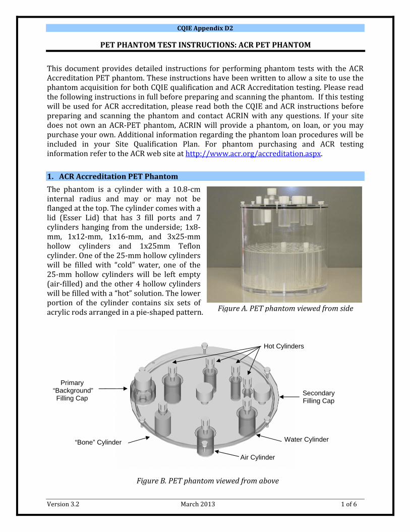
1. ACR Accreditation PET Phantom
The phantom is a cylinder with a 10.8‐cm internal radius and may or may not be flanged at the top. The cylinder comes with a lid (Esser Lid) that has 3 fill ports and 7 cylinders hanging from the underside; 1x8‐mm, 1x12‐mm, 1x16‐mm, and 3x25‐mm hollow cylinders and 1x25mm Teflon cylinder. One of the 25‐mm hollow cylinders will be filled with “cold” water, one of the 25‐mm hollow cylinders will be left empty (air‐filled) and the other 4 hollow cylinders will be filled with a “hot” solution. The lower portion of the cylinder contains six sets of acrylic rods arranged in a pie‐shaped pattern.
Figure A. PET phantom viewed from side
Secondary Filling Cap
Water Cylinder
Air Cylinder
“Bone” Cylinder
Primary “Background”
Filling Cap
Hot Cylinders
Figure B. PET phantom viewed from above
CQIE Appendix D2
PET PHANTOM TEST INSTRUCTIONS: ACR PET PHANTOM
Version 3.2 March 2013 2 of 6
2. Phantom Test Preparation
The following procedures are based on the ACR PET Accreditation phantom instructions, with minor modifications. The doses are based on the ACR Phantom Dose Chart for a 16 mCi injection, which approximates the concentration in a 70 kg patient. Two acquisitions will be acquired with a single fill of the phantom. The first acquisition will be a two‐bed position acquisition using a Body FOV. The second acquisition will immediately follow the Body FOV scan and will be a one‐bed position acquisition using a Brain FOV.
Required Materials
1 ACR‐approved PET Phantom
1 ‐ 1,000 mL bag or bottle of distilled water or saline solution
2 Tuberculin syringes (for measuring Doses A & B)
3 Large syringes (60 mL)
3 Large‐bore needles (18 gauge)
Clock or timer
CQIE ACR‐PET Phantom Dilution Worksheet
CQIE ACR‐PET Phantom Data Form (P4)
CQIE ACR‐PET Phantom SUV Analysis Form (P5)
> 1.5mCi of FDG or F‐18 fluoride are acceptable
Testing Tips – Before you begin Confirm hot lab clock and camera clock match. Ensure background of the dose calibrator is near 0 uCi at each measurement. Ensure residual activity readings are near 0 uCi at measurement; beware of external
contamination of syringes and activity remaining in needle caps.
Testing Tips – If testing will be used for CQIE qualification and ACR Accreditation The CQIE PET forms request additional information about the filling of the phantom, like
residual measurements of the doses, not requested by ACR. Therefore, it is recommended you use the CQIE forms then transfer relevant data to the ACR forms.
Instructions for Dose A and B, below, are based on a 16 mCi patient dose from the ACR Phantom Dose Chart. If your standard patient dose is not 16 mCi, please refer to the ACR Phantom Dose Chart for the appropriate doses.
Phantom Preparation
1. Empty the 4 “hot” cylinders of all water and leave the fill port screws out to allow any excess water in the cylinders to evaporate.
2. Using the primary fill port, fill the main compartment of the phantom with water several hours prior to scanning to allow time for air bubbles to collect near the top of the phantom. Also fill the “Water” cylinder in the lid.
CQIE Appendix D2
PET PHANTOM TEST INSTRUCTIONS: ACR PET PHANTOM
Version 3.2 March 2013 3 of 6
3. When ready to measure activity for the phantom, first add enough water to the body of the phantom to remove any air bubbles.
4. Draw up 0.56 +/‐ 0.05 mCi of 18F‐FDG, or F‐18 fluoride, in a tuberculin syringe and label it Dose A. For the CQIE ACR‐phantom test, the Body FOV Scan must begin 60 minutes after the measurement of Dose A.
5. Record the assay amount and assay time of Dose A on the CQIE PET Phantom Dilution Worksheet.
6. Inject Dose A into the 1,000 mL bag or bottle of saline or distilled water, repeatedly flushing the syringe to ensure that there is little residual activity left in the syringe.
7. Measure the residual activity left in the syringe for Dose A on a µCi scale and record the value and time on the CQIE PET Phantom Dilution Worksheet; this should measure near 0 µCi.
8. Discard Dose A syringe.
9. Ensure that the saline bag or bottle with Dose A is properly sealed, then mix by repeatedly inverting.
10. Using a 60 mL syringe, draw out 60 mL of the resulting radioactive solution and label that syringe Test Dose 1.
11. Set aside the radioactive solution and Test Dose 1 in a shielded area.
12. Draw up 1.32 +/‐ 0.13 mCi in a tuberculin syringe and label it Dose B.
13. Record the assay amount and assay time of Dose B on the CQIE PET Phantom Dilution Worksheet.
14. Using a fresh 60 mL syringe, withdraw ~50 mL of water from the body of the phantom.
15. Inject Dose B into the body of the phantom, repeatedly flushing the syringe to ensure that there is little residual activity left in the syringe.
16. Measure the residual activity left in the syringes for Dose B and record the values on the CQIE PET Phantom Dilution Worksheet; this should be near 0 µCi.
17. Discard Dose B syringe.
18. Cap the fill port of the phantom and repeatedly invert the phantom to thoroughly mix.
19. Open the fill port and restore the ~50 mL of water withdrawn in step 14 until the phantom body is completely filled.
20. Cap the fill port then repeatedly invert the phantom to mix the water just added.
21. Using a third 60 mLsyringe, withdraw 60 ml from the body of the phantom and label the syringe Test Dose 2.
22. Measure the activity of Test Dose 2 using a µCi scale (you will have to remove the syringe holder from the dose calibrator in order to measure the 60 mL syringes). Record dose activity and time on the ACR Phantom Dilution Worksheet.
23. Inject Test Dose 2 back into the body of the phantom and seal the phantom.
CQIE Appendix D2
PET PHANTOM TEST INSTRUCTIONS: ACR PET PHANTOM
Version 3.2 March 2013 4 of 6
24. Measure the activity of Test Dose 1 using a µCi scale. Record dose activity and time on the ACR Phantom Dilution Worksheet.
25. Use Test Dose 1 to fill the 4 “hot” cylinders in the lid of the phantom.
3. Data Acquisition and Reconstruction
When setting up the scans, enter your institution name in the patient name field (see example below). Patient Name: CQIE Name of Your Cancer Center (ex. ACRIN Cancer Center)
Positioning the Phantom
Place the phantom on its side on the scanner table. Some sheets may be used under the phantom to prevent the phantom from rolling and to assist in leveling. Align the phantom so that its long axis is parallel to the axis of the scanner. A bubble level should be used to ensure that the phantom is properly positioned in the horizontal plane. Adjust the table height so that the phantom is centered in the transverse FOV.
Body FOV Data Acquisition
The Body FOV Scan should begin 60 minutes after the measurement of Dose A. The scan length will be two bed positions. The phantom should be centered in the axial extent of the combined two bed positions. The phantom should be acquired using a standard clinical protocol for Body in accordance with the manufacturers’ recommendations. Typical imaging times, based on a 70 kg, 170 cm (~24 BMI) patient, vary from 2 – 5 minutes per bed position, depending on whether the scan acquisition is in 2D or 3D mode. Use the following acquisition parameters for the phantom scan.
a. If acquiring phantom scan for CQIE qualification only (not for ACR Accreditation): Dose = enter the sum of Dose B less the residual (Dose = Dose B – residual) Assay Time = enter the time of the Dose B measurement Weight = enter 5.78 kg Height (if required by software) = 170 cm
b. If acquiring phantom scan for CQIE and ACR Accreditation:
Dose = enter 16 mCi Assay Time = enter the time of the Dose A measurement Weight = enter 70 kg Height (if required by software) = 170 cm
Brain FOV Data Acquisition
Without moving the phantom on the bed, set up a Brain FOV acquisition. The scan length will be one bed position. Position the phantom so that the entirety of the “hot” cylinders are in the axial FOV, but include as much of the cold rod section as possible (some of the cold
CQIE Appendix D2
PET PHANTOM TEST INSTRUCTIONS: ACR PET PHANTOM
Version 3.2 March 2013 5 of 6
rod section will be cut off). Acquire a single static view of the phantom for 10 minutes if using a 3D acquisition or for 20 minutes if using a 2D acquisition.
Post Acquisition Processing (if scan acquired for ACR Accreditation)
If the phantom scan was acquired per the ACR guidelines (i.e. dose of 16 mCi and patient weight of 70 kg) the images must be edited before reconstruction. For Philips scanners, the raw data will have to be edited and the images reconstructed after editing so that fields in the header used to calculate SUVs are properly adjusted. Required edits are as follows:
Dose = enter the sum of Dose B less the residual (Dose = Dose B – residual) Assay Time = enter the time of the Dose B measurement Weight = enter 5.78 kg
Reconstruction
The Body and Brain acquisitions should be reconstructed using the same protocol as is used for typical patient studies. These protocols should be the same as those recorded on the Routine Clinical PET Protocol (PT) Form. In studies reconstructed on a Body FOV (50 – 70 cm in diameter), typical slice thicknesses range from 3 – 5 mm and typical transverse pixel sizes range in size from 3x3 – 4x4 mm2. In studies reconstructed on a Brain FOV (25 – 30 cm in diameter), typical slice thicknesses range from 2 – 5 mm and typical pixel sizes range in size from 2x2 to 4x4 mm2. Using its preferred software package, the site will sum slices to produce 9 – 12 mm thick slices for the ROI analysis (for both the Brain and Body FOVs).
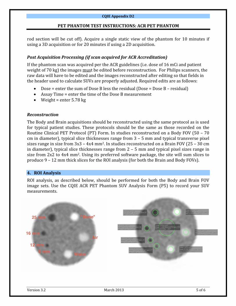
4. ROI Analysis
ROI analysis, as described below, should be performed for both the Body and Brain FOV image sets. Use the CQIE ACR PET Phantom SUV Analysis Form (P5) to record your SUV measurements.
CQIE Appendix D2
PET PHANTOM TEST INSTRUCTIONS: ACR PET PHANTOM
Version 3.2 March 2013 6 of 6
Step 1: Select the 9 – 12 mm transverse slice that best shows the four “hot” cylinders. Step 2: Draw a 2D, circular background ROI of diameter 6 – 7 cm in the center of the chosen transverse slice (avoiding cylinders). Draw a 2D, circular ROI just inside the boundaries (as visualized on PET) of the largest “hot” cylinder (25 mm cylinder). Place copies of this smaller ROI over the other visible cylinders, including the air, water and bone cylinders. All of the smaller ROIs must be the same size regardless of cylinder size. Step 3: Save a screen capture of the image from step 2; all ROIs must be visible. The screen capture should be saved as a DICOM Secondary Capture and submitted with the image set. Step 4: Record the mean and max SUVs in the appropriate section of the CQIE ACR PET Phantom SUV Analysis Form (P5), using separate forms for Brain and Body FOVs.
Recommended