MAHARASHTRA STATE BOARD OF TECHNICAL EDUCATION (Autonomous)
(ISO/IEC - 27001 - 2005 Certified)
WINTER– 16 EXAMINATION Model Answer Subject Code:
__________________________________________________________________________________________________
Page 1 of 22
17412
Important Instructions to examiners: 1) The answers should be examined by key words and not as word-to-word as given in the model answer scheme. 2) The model answer and the answer written by candidate may vary but the examiner may try to assess the
understanding level of the candidate. 3) The language errors such as grammatical, spelling errors should not be given more Importance (Not applicable for
subject English and Communication Skills. 4) While assessing figures, examiner may give credit for principal components indicated in the figure. The figures
drawn by candidate and model answer may vary. The examiner may give credit for any equivalent figure drawn. 5) Credits may be given step wise for numerical problems. In some cases, the assumed constant values may vary and
there may be some difference in the candidate’s answers and model answer.
6) In case of some questions credit may be given by judgement on part of examiner of relevant answer based on candidate’s understanding.
7) For programming language papers, credit may be given to any other program based on equivalent concept.
Q. No. Sub Q. N.
Answer Marking Scheme
1
a)
( i )
( ii )
( iii )
Attempt any SIX of the following
Define - Kinematic link --Each part of a machine, which moves relative to some other
part, is known as a ‘kinematic link (or simply link) or element. Example – any
one Example of machine element, (e.g. shaft, spindle, gear, crank, belt, pulley, key
etc. )
Different mechanism generated by single slider crank chain mechanism. (Any four)
a) Reciprocating engine, Reciprocating compressor
b) Whitworth quick return mechanism, Rotary engine,
c) Slotted crank mechanism, Oscillatory engine
d) Hand pump, pendulum pump or Bull engine,
Advantages of roller follower over knife edge follower
a) Roller follower has less wear and tear than knife edge follower.
b) Power required for driving the cam is less due to less frictional force between cam
and follower
6 x 2= 12
(01
mark)
(01
mark
(1/2 x4 =
2 mark)
(01
mark
each)
( iv )
Define slip and creep in the belt drive Slip --- Slip is defined as insufficient frictional grip between pulley (driver/driven) and
belt.
Slip is the difference between the linear velocities
of pulley (driver/driven) and belt.
Creep ----- Uneven extensions and contractions of the belt when it passes from tight side
to slack side. There is relative motion between belt and pulley surface, this
phenomenon is called creep of belt.
(01
mark
each )

MAHARASHTRA STATE BOARD OF TECHNICAL EDUCATION (Autonomous)
(ISO/IEC - 27001 - 2005 Certified)
WINTER– 16 EXAMINATION Model Answer Subject Code:
__________________________________________________________________________________________________
Page 2 of 22
17412
( v )
( vi )
(vii )
(viii)
Advantages of chain drive over belt drive (Any 4)
a) No slip takes place in chain drive as in belt drive there is slip.
b) Occupy less space as compare to belt drive.
c) High transmission efficiency.
d) More power transmission than belts drive.
e) Operated at adverse temperature and atmospheric conditions.
f) Higher velocity ratio.
g) Used for both long as well as short distances.
Effect of centrifugal tension on power transmission
As the belt passes over the pulley with high velocity, centrifugal force is produced
on the belt, which tends to act on the belt. This force tries to move the belt away
from the pulley. This force is given by,
TC = m x V2
There is no effect of centrifugal tension on power transmitted.
a) Fluctuation of energy -- The difference of maximum and minimum kinetic energy
of flywheel is known as Fluctuation of energy
b) Coefficient of fluctuation of energy -- - It is defined as the ratio of the maximum
fluctuation of energy to the work done per cycle.
It is denoted by ke = (E1 - E2)/work done per cycle
Adverse effect of imbalance of rotating elements. (Minimum two points)
a) Vibration, noise and discomfort, b) Machine accuracy get disturbed, c) Power
losses, d) More maintenance
(1/2 x 4
= 2
mark)
(02
mark)
(01
mark
each)
(02
mark)

MAHARASHTRA STATE BOARD OF TECHNICAL EDUCATION (Autonomous)
(ISO/IEC - 27001 - 2005 Certified)
WINTER– 16 EXAMINATION Model Answer Subject Code:
__________________________________________________________________________________________________
Page 3 of 22
17412
1
b
i )
Attempt any TWO of the following
State any four inversions of single slider crank mechanism. Describe any one with neat sketch
First --Reciprocating engine, Reciprocating compressor; Second -Whitworth quick return
mechanism, Rotary engine, Third-- Slotted crank mechanism, Oscillatory engine. Fourth Hand
pump, pendulum pump. ( any four name from each inversion expected)
explain any one with sketch
First --Reciprocating engine, Reciprocating compressor link 1 is fixed
Second -Whitworth quick return mechanism, Rotary engine. link 2 is fixed,
02
02

MAHARASHTRA STATE BOARD OF TECHNICAL EDUCATION (Autonomous)
(ISO/IEC - 27001 - 2005 Certified)
WINTER– 16 EXAMINATION Model Answer Subject Code:
__________________________________________________________________________________________________
Page 4 of 22
17412
Third-- Oscillatory engine. Slotted crank mechanism. link 3 is fixed
Fourth Hand pump, pendulum pump. link 4 is fixed
MAHARASHTRA STATE BOARD OF TECHNICAL EDUCATION (Autonomous)
(ISO/IEC - 27001 - 2005 Certified)
WINTER– 16 EXAMINATION Model Answer Subject Code:
__________________________________________________________________________________________________
Page 5 of 22
17412
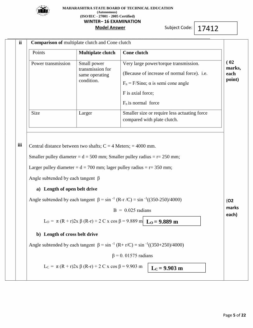
ii
iii
Comparison of multiplate clutch and Cone clutch
Points Multiplate clutch Cone clutch
Power transmission Small power
transmission for
same operating
condition.
Very large power/torque transmission.
(Because of increase of normal force). i.e.
Fn = F/Sinα; α is semi cone angle
F is axial force;
Fn is normal force
Size Larger Smaller size or require less actuating force
compared with plate clutch.
( 02
marks,
each
point)
(O2
marks
each)
Central distance between two shafts; C = 4 Meters; = 4000 mm.
Smaller pulley diameter = d = 500 mm; Smaller pulley radius = r= 250 mm;
Larger pulley diameter = d = 700 mm; lager pulley radius = r= 350 mm;
Angle subtended by each tangent β
a) Length of open belt drive
Angle subtended by each tangent β = sin -1 (R-r /C) = sin -1((350-250)/4000)
Β = 0.025 radians
LO = π (R + r)2x β (R-r) + 2 C x cos β = 9.889 m
b) Length of cross belt drive
Angle subtended by each tangent β = sin -1 (R+ r/C) = sin -1((350+250)/4000)
β = 0. 01575 radians
LC = π (R + r)2x β (R-r) + 2 C x cos β = 9.903 m
LO = 9.889 m
LC = 9.903 m

MAHARASHTRA STATE BOARD OF TECHNICAL EDUCATION (Autonomous)
(ISO/IEC - 27001 - 2005 Certified)
WINTER– 16 EXAMINATION Model Answer Subject Code:
__________________________________________________________________________________________________
Page 6 of 22
17412
2
a
b
c
Attempt any FOUR of the following
Explanation of scotch yoke mechanism with neat sketch
Machine definition --A device which transforms available energy into useful work is called as
machine
Difference of machine and structure
Machine Structure
Machine transform available energy into
useful work
Structure dose not transform energy in to
the useful work
The link of m/c made transmit both power
relative motion and forces.
The members of structure transmit forces
only.
M/c can have one or more mechanism. It does not have mechanism.
e.g. Drilling machine; Lathe machine etc. e.g. Machine frames, Bridge etc.
Klein’s construction
a) For velocity of different links
b) For acceleration of different links
4 X4 = 16
2 marks
sketch and
2 marks for
explanation
01 mark
03 marks

MAHARASHTRA STATE BOARD OF TECHNICAL EDUCATION (Autonomous)
(ISO/IEC - 27001 - 2005 Certified)
WINTER– 16 EXAMINATION Model Answer Subject Code:
__________________________________________________________________________________________________
Page 7 of 22
17412
2
d)
Define the
Term Definition Mathematical/representation
(optional)
Linear
velocity
Rate of change of linear displacement per
unit time t
x
d
dV m/sec
Angular
velocity
Rate of change of angular displacement per
unit time td
d rad/sec
Absolute
velocity
Velocity of any point with respect any point
fixed point
V ao ; velocity of point a w.r.t. o
Relative
velocity
Velocity of any point with respect to any
other some point on the same link.
V ab ; velocity of point a w.r.t. b
( 04
marks)
(O1
marks
each)

MAHARASHTRA STATE BOARD OF TECHNICAL EDUCATION (Autonomous)
(ISO/IEC - 27001 - 2005 Certified)
WINTER– 16 EXAMINATION Model Answer Subject Code:
__________________________________________________________________________________________________
Page 8 of 22
17412
2
e
Different types of follower
According to type of shape
According to type of motion of follower
According to line of motion of follower
04
(02
marks
each;
any two
sketche
s with
explana
tion)
2 f
Flat belt speed = V = 600 m/min = 600/60 m/sec = 10 m/sec;
Power transmitted = P = 4 kW ; Coefficient of friction =µ = 0.3;
Angle of lap = θ =1600

MAHARASHTRA STATE BOARD OF TECHNICAL EDUCATION (Autonomous)
(ISO/IEC - 27001 - 2005 Certified)
WINTER– 16 EXAMINATION Model Answer Subject Code:
__________________________________________________________________________________________________
Page 9 of 22
17412
03
a. i) uniform velocity.
displacement diagram:
Velocity and acceleration diagram:
ii) simple harmonic motion.
Displacement diagram:
04
mark
Belt tension ratio = T1/ T2 = eµθ = e0.3(160x π/180) = 2.31;
T1/ T2 = 2.31; T1= T2 x 2.311--------------------------------(1)
P = ( T1 - T2) x V ; --------------------------------(2)
P = ( T2 x 2.31- T2)x 10;
Putting value of power P = 4 kW
4 x1000 = ( T2 x 2.31 - T2)x 10;
T2 = 305.34 N;
T1 = 705.34N;
01
mark
1 mark
for
each
step =
03
marks
T1/ T2 = 2.31
Tmaximum = T1 = 705.34N

MAHARASHTRA STATE BOARD OF TECHNICAL EDUCATION (Autonomous)
(ISO/IEC - 27001 - 2005 Certified)
WINTER– 16 EXAMINATION Model Answer Subject Code:
__________________________________________________________________________________________________
Page 10 of 22
17412
Velocity and acceleration diagram:
iii) uniform acceration and retardation.
Displacement diagram:
Velocity and acceleration diagram:

MAHARASHTRA STATE BOARD OF TECHNICAL EDUCATION (Autonomous)
(ISO/IEC - 27001 - 2005 Certified)
WINTER– 16 EXAMINATION Model Answer Subject Code:
__________________________________________________________________________________________________
Page 11 of 22
17412
b. Relative Velocity Method.
Given Data:
Crank = 0.5m
Connecting rod=2m
N= 180 rpm
Θ =450
A) Space diagram:
Scale:
1cm= 0.25m
ω=𝟐𝚷𝐍
𝟔𝟎
𝟐𝚷𝐗𝟏𝟖𝟎
𝟔𝟎
ω = 18.84 rad/s
Calculations:
1)VOA= rω
= 0.5 X 18.84
VOA = 9.42 m/s ….1 mark
B)Velocity diagram:
Scale:
1 cm=3m/s
2) Velocity of piston:
Vp= L(op) X scale
=2.8 X3
01
01

MAHARASHTRA STATE BOARD OF TECHNICAL EDUCATION (Autonomous)
(ISO/IEC - 27001 - 2005 Certified)
WINTER– 16 EXAMINATION Model Answer Subject Code:
__________________________________________________________________________________________________
Page 12 of 22
17412
Vp=8.4 m/s …..ans
3) Angular velocity of connecting rod:
ω=𝑽𝒂𝒑
𝒍𝒆𝒏𝒈𝒕𝒉 𝒐𝒇 𝑨𝑷 =
𝒍(𝒂𝒑)𝑿 𝑺𝒄𝒂𝒍𝒆
𝟐 =
𝟐.𝟐𝑿𝟑
𝟐
ω= 3.3 rad/sec…..ans
01
01
03
c.
d.
e.
Θ1=00 Θ2=600 θ 3= 1500
Resolving Horozontally,
∑H= m1r1cos θ1 + m2r2cos θ2 + m3r3cos θ3
=200 cosoo + 500 cos 600+ 225 cos 1500
=255.14 ……………………1 mark
Resolving vertically,
∑V = m1r1sin θ1 + m2r2sin θ2 + m3r3sin θ3
=200 sin oo + 500 sin 600 + 225 sin 1500 =545.51 …………………..1mark
Sr.
no. Parameters Cross belt drive Open belt drive
1 Velocity ratio High velocity ratio Low velocity ratio
2 Direction of
driven pulley
Rotated in same
direction as the driving
as the driving pulley
Rotated in the opposite direction to the
driving pulley
3 Application Sawmills, buck saws Conveyors, electrical generator
4 Length of belt
drive L=Π(r1+r2)+2C+
(𝑟1−𝑟2 )2
𝐶 L=Π(r1+r2)+2C+
(𝑟1+𝑟2 )2
𝐶
SR.
No.
Name of brake Applications
1 Band brake Drums and chain saws, Railway braking system.
2 Disc brake Any rotating shaft, motor cycles
3 Internal
expanding brake
All type of light vehicles( motor cars, 2 wheelers),light
truks
4 External shoe
brake
Railway coach, electric cranes
1 mark
for
each
point.
1 mark
for any
1
applica
tion
∑H=01
∑V=01
Mb=01
Θ’=01
MAHARASHTRA STATE BOARD OF TECHNICAL EDUCATION (Autonomous)
(ISO/IEC - 27001 - 2005 Certified)
WINTER– 16 EXAMINATION Model Answer Subject Code:
__________________________________________________________________________________________________
Page 13 of 22
17412
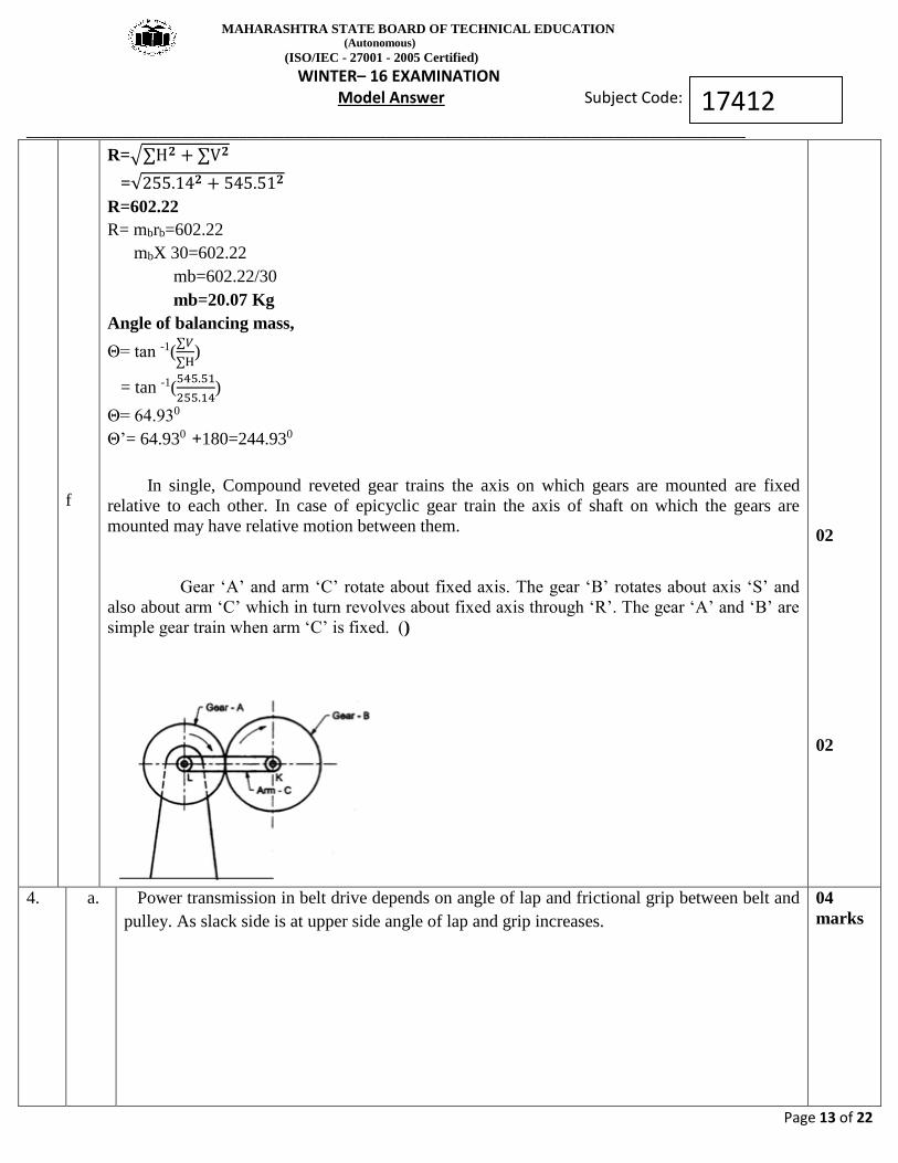
f
R=√∑H𝟐 + ∑V𝟐
=√255.14𝟐 + 545.51𝟐
R=602.22
R= mbrb=602.22
mbX 30=602.22
mb=602.22/30
mb=20.07 Kg
Angle of balancing mass,
Θ= tan -1(∑𝑉
∑H)
= tan -1(545.51
255.14)
Θ= 64.930
Θ’= 64.930 +180=244.930
In single, Compound reveted gear trains the axis on which gears are mounted are fixed
relative to each other. In case of epicyclic gear train the axis of shaft on which the gears are
mounted may have relative motion between them.
Gear ‘A’ and arm ‘C’ rotate about fixed axis. The gear ‘B’ rotates about axis ‘S’ and
also about arm ‘C’ which in turn revolves about fixed axis through ‘R’. The gear ‘A’ and ‘B’ are
simple gear train when arm ‘C’ is fixed. ()
02
02
4.
a.
Power transmission in belt drive depends on angle of lap and frictional grip between belt and
pulley. As slack side is at upper side angle of lap and grip increases.
04
marks

MAHARASHTRA STATE BOARD OF TECHNICAL EDUCATION (Autonomous)
(ISO/IEC - 27001 - 2005 Certified)
WINTER– 16 EXAMINATION Model Answer Subject Code:
__________________________________________________________________________________________________
Page 14 of 22
17412
b.
Oldham’s coupling is used for connecting too parallel shafts whose axis are a small
distance a part the shafts are coupled in such a way that if one shaft rotates the other shaft also
rotate at same speed.
This mechanism is obtained by fixing link 2 which is shown in fig. The shafts to be
connected have two flanges namely link 1 and links 3 are rigidly fasten at their end by pair with
link2. The link 4 is a single part but acting in two ways so link 4 form two sliding pair.
When the driving shaft N rotates the flange ‘A’ causes the intermediate piece (Centre
Block) to rotate at same angle through which flange has rotate and it further rotate the flange B
(link 3) at same angle and thus shaft M rotates.
Fig.2m
arks+ 2
marks
explan
ation.
4.
c.
Sr.
No. Flywheel Governor
1
The flywheel stores the energy and gives
up the energy whenever required during
cycle.
It regulates the speed by regulating the
quantity of charge of prime mover.
2 It has no control over the quantity of
working fluid.
Governor takes care of quantity of working
fluid.
3 It regulates the speed during one cycle
only. It regulates the speed over period of time.
4 It is not essential element for every prime
mover. It is an essential element of a prime mover.
5 It is used in toys, IC engine, hand
watches. It is used in automobile vehicles.
1 mark
each
for any
4
points

MAHARASHTRA STATE BOARD OF TECHNICAL EDUCATION (Autonomous)
(ISO/IEC - 27001 - 2005 Certified)
WINTER– 16 EXAMINATION Model Answer Subject Code:
__________________________________________________________________________________________________
Page 15 of 22
17412
d.
It consist of two or more ropes wound around flywheel on ream of pulley rigidly fixed to
the shaft of an engine. The upper end of rope is attached to a spring balance while the lower end
of the rope is kept in position by applying dead weight.
To prevent slipping of rope over flywheel wooden blocks are used which is placed at
intervals around the circumference of flywheel.
The operation of brake the engine is made to run at constant speed the frictional torque
due to rope must be equal to torque being transmitted by the engine. Net brake load = W – S.
Therefore, frictional torque due to ropes = torque transmitted by engine at constant
speed.
Brake power (P) = Torque transmitted into angular speed of engine.
If diameter of rope is neglected then, P = (𝑊−𝑆)𝜋𝐷𝑁
60
Applications:-It is commonly used for measuring brake power of the engine.
Fig.2m
arks 2
marks
explan
ation.

MAHARASHTRA STATE BOARD OF TECHNICAL EDUCATION (Autonomous)
(ISO/IEC - 27001 - 2005 Certified)
WINTER– 16 EXAMINATION Model Answer Subject Code:
__________________________________________________________________________________________________
Page 16 of 22
17412
e.
f.
fig. shows a mechanical brake or internal expanding brake used in automobile vehicles.
Construction:-
1) It consists of two semi-circular brake shoe having friction lining on their outer
surface.
2) Brake shoes are hinged to back plate at lower end by an anchor pin while other end
rest on cam.
3) The cams turns or actuate by camshaft passes through the hole in back plate.
4) The camshaft can be operated by brake pedal through linkage.
5) The outer portion of brake is brake drum which encloses the complete brake msm
and protect it from dust and moisture.
Working:-
1) When break pedal is pressed the cam turn to outwear by expanding the brake shoe
against the retractor spring force.
2) The friction lining comes in contact with drum and causes friction between them.
3) This force of friction oppose the direction of motion and by reducing the speed or
stop vehicle.
4) When brake pedal is released the retracting spring pull the brake shoe inward which
turn the cam and brakes are released.
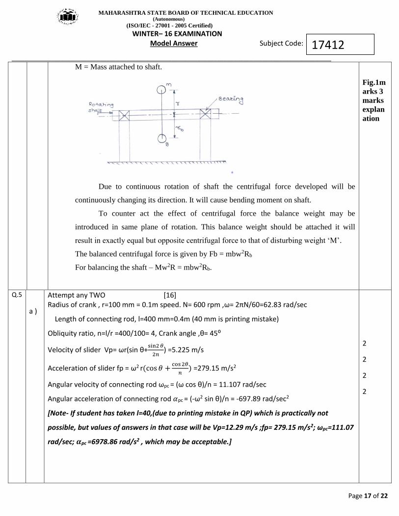
m = Mass attached to shafts, r = Distance of CG from axis of rotation.
Consider mass ‘m’ is attached to rotating shaft at a radius are then the centrifugal force
exerted by mass ‘M’ on the shaft is Fc = Mw2R
Where,
W = Angular velocity of shaft
R = Distance of CG from axis of rotation
Fig.2m
arks 2
marks
explan
ation
MAHARASHTRA STATE BOARD OF TECHNICAL EDUCATION (Autonomous)
(ISO/IEC - 27001 - 2005 Certified)
WINTER– 16 EXAMINATION Model Answer Subject Code:
__________________________________________________________________________________________________
Page 17 of 22
17412
M = Mass attached to shaft.
Due to continuous rotation of shaft the centrifugal force developed will be
continuously changing its direction. It will cause bending moment on shaft.
To counter act the effect of centrifugal force the balance weight may be
introduced in same plane of rotation. This balance weight should be attached it will
result in exactly equal but opposite centrifugal force to that of disturbing weight ‘M’.
The balanced centrifugal force is given by Fb = mbw2Rb
For balancing the shaft – Mw2R = mbw2Rb.
Fig.1m
arks 3
marks
explan
ation
Q.5
a )
Attempt any TWO [16] Radius of crank , r=100 mm = 0.1m speed. N= 600 rpm ,ω= 2πN/60=62.83 rad/sec
Length of connecting rod, l=400 mm=0.4m (40 mm is printing mistake)
Obliquity ratio, n=l/r =400/100= 4, Crank angle ,θ= 45⁰
Velocity of slider Vp= ωr(sin θ+sin2 𝜃
2𝑛) =5.225 m/s
Acceleration of slider fp = ω2 r(cos 𝜃 +cos 2𝜃
𝑛) =279.15 m/s2
Angular velocity of connecting rod ωpc = (ω cos θ)/n = 11.107 rad/sec
Angular acceleration of connecting rod 𝛼pc = (-ω2 sin θ)/n = -697.89 rad/sec2
[Note- If student has taken l=40,(due to printing mistake in QP) which is practically not
possible, but values of answers in that case will be Vp=12.29 m/s ;fp= 279.15 m/s2; ωpc=111.07
rad/sec; 𝜶pc =6978.86 rad/s2 , which may be acceptable.]
2
2
2
2
MAHARASHTRA STATE BOARD OF TECHNICAL EDUCATION (Autonomous)
(ISO/IEC - 27001 - 2005 Certified)
WINTER– 16 EXAMINATION Model Answer Subject Code:
__________________________________________________________________________________________________
Page 18 of 22
17412
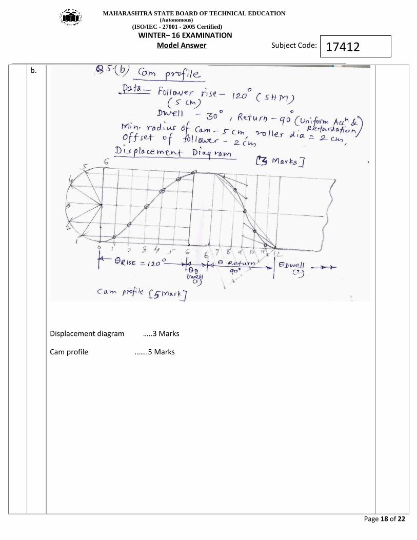
b.
Displacement diagram …..3 Marks
Cam profile …….5 Marks

MAHARASHTRA STATE BOARD OF TECHNICAL EDUCATION (Autonomous)
(ISO/IEC - 27001 - 2005 Certified)
WINTER– 16 EXAMINATION Model Answer Subject Code:
__________________________________________________________________________________________________
Page 19 of 22
17412
6
c
a.
Band and block brake
No. of blocks n=14 ; θ= 16⁰ ;𝜇 = 0.3 braking force= 300N
𝑇𝑛
𝑇𝑜= [
1+𝜇 tan𝜃
2
1−𝜇 tan𝜃
2
]n =3.26 …. 4 M
To X 10=300 X 60 ; To =1800 N ; Tn = 1800 X 3.26 = 5868 N Let rb = radius of brake drum (Not
given). If we consider it as 10 cm,
rb = (5868-1800) X 0.1 =406.8 N m …..….. 4M

MAHARASHTRA STATE BOARD OF TECHNICAL EDUCATION (Autonomous)
(ISO/IEC - 27001 - 2005 Certified)
WINTER– 16 EXAMINATION Model Answer Subject Code:
__________________________________________________________________________________________________
Page 20 of 22
17412
b.
Attempt any TWO …..[16] a ) (i) Define …(.1 for each definition with sketch)
(1) Pitch circle- Circle drawn from centre of cam through pitch points (2) Pressure angle- Angle between direction of follower motion and normal to pitch curve (3) Stroke- Maximum travel of follower from its lowest position to top most position (4) Module –(Gears) – Ratio of pitch circle diameter in mm to No. of teeth on gear
(ii) Differentiate (Any four points ; 4 X 1 =4 Marks)
DISC BRAKE DRUM BRAKE
It uses disc shaped rotors It uses cylindrical drum
It uses a clamp called caliper to hold the
friction ‘pads’ against rotor disc
It uses expanding hydraulic cylinder to press
the friction material (shoes) against the
inside of rotating drum.
Good braking even at high temperature Reduced performance at high temp.
Better heat dissipation Slower heat dissipation
Fast braking, better braking force Slow braking
Cost is more Cheaper than disc brake
Generally Used for modern bikes, cars Used for trucks, bus, scooter
(b) Four bar chain Velocity Diagram ….2M ; Acceleration Diagram …..2M

MAHARASHTRA STATE BOARD OF TECHNICAL EDUCATION (Autonomous)
(ISO/IEC - 27001 - 2005 Certified)
WINTER– 16 EXAMINATION Model Answer Subject Code:
__________________________________________________________________________________________________
Page 21 of 22
17412
Calculations-
VQP = ωQP X PQ =10 X 0.0625 = 0.625 m/s
From Velocity diagram,
By measurement, VRQ =0.333 m/s,; ωQR = VRQ /RQ =0.333/0.175 =1.9 rad/s (Anti clockwise)…1M
By measurement, VRS =0.426 m/s,; ωRS = VRS /SR =0.426/0.1125 =3.78 rad/s (clockwise)…..1M
Find out radial acceleration of each link by using formula -V2/length of link
FrQP =6.25 m/s2 ; frRQ = 0.634 m/s2 ; frRS = 1.613 m/s2
From acceleration diagram, measure all tangential components (ft)
Angular acceleration of link QR , 𝛼QR = ft RQ /QR =4.1/0.175= 23.43 rad/s2 (Anti clockwise)…1M
Angular acceleration of link RS , 𝛼RS= ft RS /SR =5.3/0.1125= 47.1 rad/s2 (Anti clockwise) …1M

MAHARASHTRA STATE BOARD OF TECHNICAL EDUCATION (Autonomous)
(ISO/IEC - 27001 - 2005 Certified)
WINTER– 16 EXAMINATION Model Answer Subject Code:
__________________________________________________________________________________________________
Page 22 of 22
17412
c
Recommended