Magnetic Flux Ropes in Space Plasmas
Mark Moldwin
UCLA
2007 Heliophysics Summer School
With thanks to Mark Linton at NRL
Goal of Lecture
• Introduce one of the most ubiquitous features in space plasmas
• Describe their Origin, Evolution, Structure, and impact
• Will present combination of simulations, observations, and synthesis models

What is a Flux Tube?
• Ideal MHD’s frozen-in flux condition• Equation of motion has the pressure gradient
and Lorentz term on RHS• Magnetic force has two components -
magnetic pressure term acting perpendicular to field and a tension term along field.
• Can think of flux tubes as mutually repulsive rubber bands
Pop Quiz
• BACKGROUND: Spacecraft X observes a magnetic field change over Y units of time.
• How do you know if the observed change in B is due to the relative motion of a boundary past the spacecraft or dynamics/global change/transient in the background configuration?

Lesson
• Must make models to understand global structure and dynamics
• Must use statistics to understand global structure and dynamics
• Must make multiple, simultaneous, distributed measurements to understand global structure and dynamics
What are Flux Ropes, and Who Cares?
• Magnetized plasmas can form structures on various scales - shocks, discontinuities, waves, flux tubes, current sheets etc.
• Some are created by magnetic reconnection and can have sharp and clear boundaries
• Provide evidence of dynamics AND can give rise to significant energy and momentum flow from one region to another

Coronal Mass Ejections are the primary driver of majorGeomagnetic storms
Their structure determines their geomagnetic effectiveness

Pop Quiz
• Draw a cartoon model of the structure produced by magnetic reconnection in the lower corona to make a CME.
• What does it look like?• How would you describe it without using
technical words?

Creation of Coronal Mass Ejection by Reconnection in Solar Magnetic Fields
What is wrong with this picture?

CME Structure
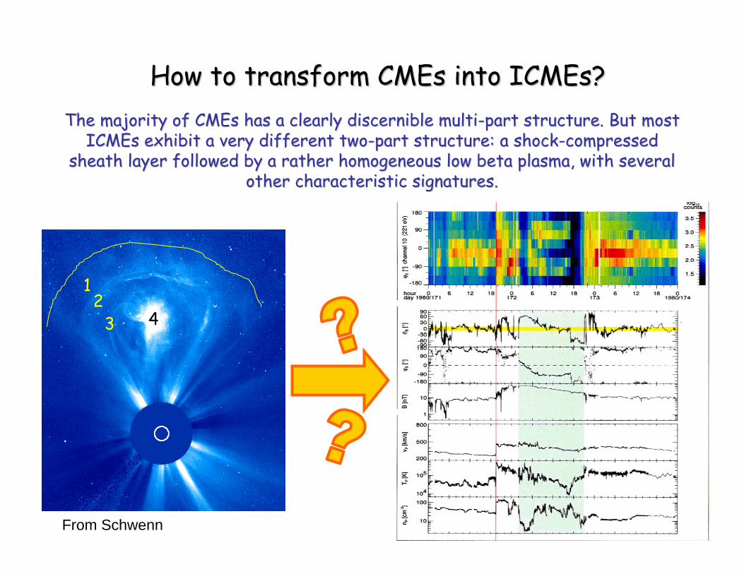
How How to to transform CMEs into ICMEstransform CMEs into ICMEs??
12
3 4
The The majority majority of CMEs has a of CMEs has a clearly discernible multiclearly discernible multi--part structurepart structure. . But most But most ICMEs ICMEs exhibit exhibit a a very very different different twotwo--part structurepart structure: a : a shockshock--compressed compressed
sheath layer followed by sheath layer followed by a a rather homogeneous low beta plasmarather homogeneous low beta plasma, , with several with several other characteristic signaturesother characteristic signatures..
From Schwenn

Russell and Elphic
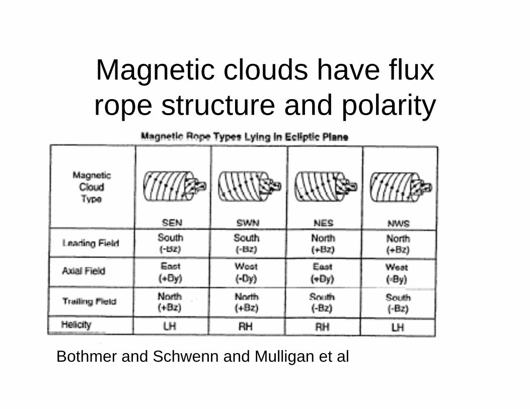
Magnetic clouds have flux rope structure and polarity
Bothmer and Schwenn and Mulligan et al

Li and Luhmann, 2004 Polarity has solar cycle dependence

• Breakout CME: reconnection in front of CME allows it to erupt
• Most models: reconnection behind CME, cuts fieldlines connecting it to the Sun, and causes flaring and particle acceleration
• In some models, reconnection below CME is main driver of eruption
Formation of Coronal Mass Ejection
MacNeice et al. 2004
QuickTime™ and aBMP decompressor
are needed to see this picture.

3D Model of CME (Lynch et al)
Legs of CME collide at an oblique angle. Flare reconnection forms tangled arcade below, 3D flux rope/knot above.Reconnection with guide field is key to understanding CME’s.
QuickTime™ and a decompressor
are needed to see this picture.

QuickTime™ and a decompressor
are needed to see this picture.

Russell

CME Current Sheet Evolution
• CME erupts with the field still attached to the photosphere
• Eruption brings CME legs together –forces a current sheet to develop
• Reconnection is then initiated in the current sheet, cutting the fieldlines which attach the CME to the photosphere

Shear magnetic field, then cancel flux by diffusion,reconnection at photosphere. This creates a twisted flux rope. For strong shear, the Rope erupts, reconnecting with overlying field.
Note: In this scenario, formation of flux rope happens beforeeruption. In “breakout” flux rope forms during/after eruption.
3D Model of CME – Flux Cancellation(Amari et al 2003)

3D effects in CME Generation
• Guide field is likely to be common in current sheets behind erupting CME and in the magnetotail
• Reconnection will be “component” rather than exactly anti-parallel
• Resulting flux rope will have twist wrapping around the guide field
• Tangling of CME field-lines will result if more than one reconnection region is excited


Observation of Coronal Mass Ejection
• Eruption from Corona of magnetic field and plasma
• Magnetic field bulges out, then pinches together behind eruption, leading to post-CME reconnection
• Coronograph and in-situ measurements both consistent with twisted flux rope magnetic structure
LASCO C2 Coronagraph
QuickTime™ and aYUV420 codec decompressor
are needed to see this picture.

ICME Magnetic Signatures
Flux rope signature:Increase in magnetic field strength within flux rope. Strong component of twist (Bz) and guide field (By) are both present.

Reconnection across HCS?
• New class of flux ropes discovered in solar wind (Moldwin et al., 2001)
• Scale order of an hour

Cartwright and Moldwin, 2007
Small Flux Rope Properties

Magnetotail Current Sheet Evolution
• Solar wind extends Magnetotail on night side of Earth
• Disturbance in solar wind, sets off reconnection in Magnetotail
• Plasmoid forms between reconnection site and pre-existing tailward X-point
• Plasmoid is ejected from Magnetotail

Creation of Plasmoid by Magnetic Reconnection in Earth’s Magnetotail

Formation of Plasmoid
Magnetotail current sheet forms – similar to Post-CME current sheet. Localized reconnection forms plasmoid, tearing mode can lead to tangling, multiple plasmoids, as in post CME flare.

Plasmoid Magnetic Signatures
Magnetotail plasmoidstructure: magneticfeatures show same flux rope twisted structure with guide field as is seen in CME fields.

Plasmoid Formation in Magnetotail
Start with magnetotail-type configuration.Perturb the equilibrium, pinch off region in tail, creating X-point.Reconnection at X-point generates disconnected island/plasmoid.
Hesse & Schindler (2001)

Generation of Multiple Islands/Plasmoids under Magnetotail conditions
Daughton, Scudder,& Karimabadi, 2006
Long current sheet, with openboundaries, e.g. Magnetotail,Is unstable to spontaneoustearing. Leads to generation and ejection of multiple magnetic islands/plasmoids

Plasmoid Core Field correlation with IMF By Direction(same as Magnetic Cloud Core Field
correlated with source field)

Properties of Flux Ropes
• Helical field structures with core fields• Often current sheets at edges• Wide range of scales• Magnetic Reconnection needed for
formation• Carry significant energy, mass,
momentum

Flux Rope Model
• Simplist model is a force free cylindrical model that can be represented by Bessel functions
• Force Free J x B = 0• What is a none trivial or potential field
solution to this equation?

Lundquist Soln
• μοJ = αB• So J has to be parallel to B and α is
some scalar function of position and time
• If α is constant then from Ampre’s law get a Helmholtz Equation whose solution are Bessel functions.

Flux Ropes
• The center of the rope is the core field
• Edges of rope often have current sheets to separate it from surrounding plasma

Double Helix Nebule
• IR image• Near center of Milky
Way• About 80 LY longMorris et al. Nature,
2007

Hubble Image of Planetary Nebula
• Twisted knots suggestive of flux ropes
• Scale 100s of AUDahlgren et al., 2007
Take Home Message• Flux Ropes are formed by reconnection or
strong shearing of magnetic fields• Observed throughout space• Guide field is often present – creates twisted
flux rope, with twist field wrapped around an axis of guide field
• Play significant role in energy, mass, and momentum transfer in Sun-Earth relationship (CMEs and storms, magnetotail flux rope plasmoids and substorms)
Recommended


![Survival of flux transfer event (FTE) flux ropes far along ...shay/papers/EastwoodJ.2012.JGR.117.A08222.… · of ARTEMIS P1. [8] Figure 2 shows an overview of the data. The upstream](https://img.pdfslide.us/doc/110x75/60d2b5c18451152390051639/survival-of-flux-transfer-event-fte-flux-ropes-far-along-shaypaperseastwoodj2012jgr117a08222.jpg)