SEC
TIO
N 7
7 R e l a y s - E n e r g y C o n s e r v i n g
S e c t i o n
www.magnecraft.com 847-441-2540

SEC
TIO
N 7
Magnecraf t Solut ion Guide 105A Magnecraf t Solut ion Guide 105A
755785
711
303 Series
385
Latching, Sequence and Impulse Relays – Application Data
Energy Conservation RelaysIn many applications it is important for the customer to conserve electrical energy. One approach to energy conservation in an electrical system is to use relays that do not require constant power to maintain contact closure.
“Latching relay” is a generic term that is used to describe a relay that maintains its contact position after the control power has been removed. Latching relays allow a customer to control a circuit by simply providing a single pulse to the relay control circuit. Latching relays are also desirable when the customer needs to have a relay that maintains its position during an interruption of power.
There are three main types of Latching relays. Magnetic latching, Mechanical Latching and Impulse Sequencing.
Magnetic Latching RelaysMagnetic Latching relays require one pulse of coil power to move their contacts in one direction, and another, redirected pulse to move them back. Repeated pulses from the same input have no effect. Magnetic Latching relays are useful in applications where interrupted power should not be able to transition the contacts.
Magnetic Latching relays can have either single or dual coils. On a single coil device, the relay will operate in one direction when power is applied with one polarity, and will reset when the polarity is reversed. On a dual coil device, when polarized voltage is applied to the reset coil the contacts will transition. AC controlled magnetic latch relays have single coils that employ steering diodes to differentiate between operate and reset commands.
Mechanical Latching RelaysMechanical latching relays use a locking mechanism to hold their contacts in their last set position until commanded to change state, usually by means of energizing a second coil. Since the relay does not rely on a magnet, the locking strength will not degrade over time or weaken during thermal cycling. The contacts will remain locked in the directed position until the opposing coil has been energized. Packaging machinery that places several units into a single container would be a good example.
Impulse RelaysImpulse relays are a form of latching relay that transfers the contacts with each pulse. Many impulse relays are made up of a magnetic latch relay and a solid state steering circuit that, upon application of power, determines which position the relay is in and energizes the opposite coil. The contacts transfer and hold that position when power is removed. When reenergized, the contacts transfer again and hold that position, and so on. In order to transfer the contacts, one simply provides a single unidirectional pulse. There is no need to redirect the control pulse or reverse the polarity.
Impulse relays can be used as wear equalizers. They are well suited for applications such as turning a single device on or off from one or more locations with a single momentary switch or push button at each station. For example, a conveyor could be started and/or stopped from multiple locations by means of a single button at each position.
7/2

Magnecraf t Solut ion Guide 105A
SEC
TIO
N 7
Magnecraf t Solut ion Guide 105A
INDUSTRIALAUTOMATION
PACKINGMACHINES
PUMPINGMACHINES COMPRESSORS
INDUSTRIALFANS
INDUSTRIALAPPLIANCES
www.magnecraft.com 847-441-2540
Alternating Relay – Application Data
Applications:
712 Alternating RelayIn many industrial pumping applications, two identical pumps are used for the same job. A standby unit is available in case the first pump fails. However, a completely idle pump might deteriorate and provide no safety margin. Alternating relays prevent this by assuring that both pumps get equal run time.
The Model 712 Series Alternating Relay is designed for duplex pumping systems where it is desirable to equalize pump run time. The solid state alternating circuit drives an internal electromechanical relay. A continuous power source and control switch is required.
The control switch (float, pressure or other isolated contact) is connected as shown in the respective wiring diagrams. Each time the control switch is opened the output contacts will change status. Indicator lights on the case show the internal relay status. Setting the top toggle switch to the “center position” alternates the load; while setting the switch to “Load 1” or “Load 2” will lock the relay in the respected position, preventing alternation.
The alternating relay approach isn’t limited to pumping applications. The control switches could be thermostats or pressure switches, and the loads could be fans or compressors.
7/3

SEC
TIO
N 7
Magnecraf t Solut ion Guide 105A Magnecraf t Solut ion Guide 105A
1.40(35.6)
1.54(39.1)
2.63(66.8)
AA1
7
11
14
4
12
1
BA2
921
24
6
22
3
.187 QUICK CONNECTS
CONTACTS7 & 4
7 & 1
CLOSED9 & 6
9 & 3
INDICATING LEDS
IECNEMA
+ –
UL RecognizedFile No. E43641
UL USCUL Listed When Used
With Magnecraft Sockets.
711 Impulse Sequencing Relay/DPDT 12 Amp Rating
LED IndicatesClosed Contact
Optional Flangeand DIN Adapter
Mounting
The 711 Impulse Sequencing relay is an alternating relay used for load sharing or toggling ON/OFF of the load. Uni-directional momentary pulses cause the contacts to transfer from one side to the other. There is no need to redirect the polarity of the input in order to change and maintain states.
WIRING DIAGRAM
Standard Blade Style Socket Mounting Configuration
Units
AV
ResistiveResistive
HPHPmA
VV
VAW
(Resistive)
msV(rms)V(rms)V(rms)
°C°Cg-ng-n
grams
711XBXDPDT
Silver Alloy12300
12A @ 240V 50/60Hz12A @ 28V
1/3 @ 120 VAC1/2 @ 240 VAC
100 @ 5VDC (.5W)
12….120, 50/60 Hz12….110
85% to 110%80% to 110%
1.81.815%10%
100,00010,000,000
3515005001500
UL-40…+85-40…+55
3, 10 - 55 Hz10
IP 40110
% of Nominal
Operations @ Rated CurrentUnpowered
Between coil and contactBetween polesBetween contacts
Standard versionStorageOperationOperational
Contact Characteristics Number and type of ContactsContact materialsThermal (Carrying) CurrentMaximum Switching VoltageSwitching Current @ Voltage
Minimum Switching Requirement
Coil CharacteristicsVoltage Range
Operating Range
Average consumption
Drop-out voltage threshold
Performance CharacteristicsElectrical Life (UL508)Mechanical LifeOperating time (response time)Dielectric strength
EnvironmentProduct certificationsAmbient air temperaturearound the deviceVibration resistanceShock resistanceDegree of protectionWeight
General Specifications (UL 508)
~
~~~~
~~~
7/4

Magnecraf t Solut ion Guide 105A
SEC
TIO
N 7
Magnecraf t Solut ion Guide 105A
2.63(66.8)
(80)3.14
(26)1.03
(81)3.18
(91)3.6
0.40(10)
Other mating sockets see Section 2: 70-124-1, 70124-2, 70178-1, 70-178-2
16-711C1Section 3, p.14-16
16-711C4Section 3, p.14-16
711 Relay with the 70-463-1 Socket
BOLD-FACED PART NUMBERS ARE NORMALLY STOCKED
www.magnecraft.com 847-441-2540
Coil Resistance
70 Ohms220 Ohms880 Ohms
5700 Ohms
70 Ohms220 Ohms880 Ohms
5700 Ohms
Part Number(Without LEDs)
711XBXC-12A711XBXC-24A711XBXC-48A711XBXC-120A
711XBXC-12D711XBXC-24D711XBXC-48D711XBXC-110D
Part Number(With LEDs)
711XBXCL-12A711XBXCL-24A
711XBXCL-48A711XBXCL-120A
711XBXCL-12D711XBXCL-24D711XBXCL-48D711XBXCL-110D
Nominal Voltage
AC Operated12 VAC 50/60 HZ24 VAC 50/60 HZ48 VAC 50/60 HZ120 VAC 50/60 HZ
DC Operated12 VDC24 VDC48 VDC110 VDC
Standard Part Numbers
70-463-1SOCKET
16-1351Metal Hold-Down ClipSee Section 3 p.8-11
RelayAdapters
7/5

SEC
TIO
N 7
Magnecraf t Solut ion Guide 105A Magnecraf t Solut ion Guide 105A
Load 1 IndicatorIndicates when Load 1 is Active.
Top Toggle SwitchTo Lock Load in Position.
Highest GradeElectronic Components
RoHS Compliant.
Industry Standard 8 or 11 PinOctal Socket CompatibleEasy Installation and Replacement.
Industry Proven PowerRelay Technology12 Amp Relay with Dual Voltage Capability.
UL Listed when 712 Relayand Octal Socket are Combined
UL Approved for Field Replacement.
Load 2 IndicatorIndicates when Load 2 is Active.
The Complete System
Solution!
Advantages of the 712 Alternating Relay
The Model 712 series Alternating Relay is designed for duplex pumping systems where it is desirable to equalize pump run time. The solid state alternating circuit drives an internal electromechanical relay. A continuous power source and control switch are required.
The control switch (float, pressure or other isolated contact) is connected between the L1 terminal and the control terminal. Each time the control switch is opened the output contacts will change status. Indicator lights on the case show the internal relay status.
Setting the top toggle switch to Load 1 or Load 2 will lock the relay in position, preventing alternation.
• Offers a “one stop solution” for your pump management system.
• Several configurations available to meet your individual needs.
• Switching capabilities up to 12 amps.
• Two LED status indicators; indicate status of the separate loads independently.
• Dual Voltage Coils eliminate the need to specify AC or DC (AC only for 240 volts).
• Only 36 mm’s wide; does not take up any additional room on the DIN rail.
• Color and appearance designed for high visibility in all environments.
• Engineering availability allows for customized control system solutions. 16-711C1
FLANGE ADAPTER16-711C4
DIN RAIL ADAPTER
See Section 3 p.14-16
7/6

Magnecraf t Solut ion Guide 105A
SEC
TIO
N 7
Magnecraf t Solut ion Guide 105A
Load 1 IndicatorIndicates when Load 1 is Active.
Top Toggle SwitchTo Lock Load in Position.
Highest GradeElectronic Components
RoHS Compliant.
Industry Standard 8 or 11 PinOctal Socket CompatibleEasy Installation and Replacement.
Industry Proven PowerRelay Technology12 Amp Relay with Dual Voltage Capability.
UL Listed when 712 Relayand Octal Socket are Combined
UL Approved for Field Replacement.
Load 2 IndicatorIndicates when Load 2 is Active.
7/7

SEC
TIO
N 7
Magnecraf t Solut ion Guide 105A Magnecraf t Solut ion Guide 105A
(36)1.4
(65)2.6
(2)0.08
0.4(10.2)
(44)1.73
3.3(83.5)
General Specifications (UL 508)
~
% of Nominal
Maximum
Operations @ Rated CurrentUnpoweredBetween coil and contactBetween polesBetween contacts
Standard versionStorageOperation
~~
~~~~
~
~~~
712 Relay with the 70-750DL8-1 Socket
UL RecognizedFile No. E43641
UL USCUL Listed When Used
With Magnecraft Sockets.
712 Alternating Relay/DPDT, 12 Amp Rating
Optional FlangeMounting
Load 1 Indicator
Load 2 Indicator
Toggle Switch
Proven RelayTechnology
Units
AV
ResistiveResistive
HPHP
Pilot DutymA
VVVVVWV
VDC
sms
(Resistive)
V(rms)
V(rms)V(rms)
°C°C
grams
712XAXCSPDT
Contact Characteristics Number and type of Contacts
Contact materialsThermal (Carrying) CurrentMaximum Switching VoltageCurrent ratingSwitching voltage
Minimum Switching Requirement
Coil CharacteristicsVoltage Range
Operating Range
Average consumption
Drop-out voltage threshold
Timing CharacteristicsTime Delay - FixedReset TimeAlternating Action
Performance CharacteristicsElectrical Life (UL 508)
Mechanical LifeRated insulation voltage
Dielectric strengthrms voltage
EnvironmentProduct certificationsAmbient air temperaturearound the deviceDegree of protectionWeight
712XBXCDPDT CROSS
WIRED
712XBXCKDPDT, PIN 9 - NO
PIN 11 - NC
712XBXCK1DPDT, PIN 9 - NC
PIN 11 - NOSilver Alloy
12300
12A @ 240V 50/60Hz12A @ 30V
1/3 @ 120 VAC1/2 @ 240 VAC
B300100 @ 5 VDC (.5W)
12, 24, 120240
80% to 110%80% to 110%
1.81.815%10%
0.5100
Release of Control Switch
100,000
10,000,0001500
5001500
UR, CSA, CE-30…+70-20…+60
IP 40120
WHITE
7/8

Magnecraf t Solut ion Guide 105A
SEC
TIO
N 7
Magnecraf t Solut ion Guide 105A
(96)3.77
(75)2.95
1.1(28)
(37)1.45
(65)2.6
(2)0.08
0.4(10.2)
Other mating sockets see Section 2: 70-750DL11-1, 70-750E8-1, 70-750E11-1, 70-464-1, 70-465-1, 70-169-1, 70-170-1
16-711C1Section 3, p.14-16
16-711C4Section 3, p.14-16
RelayAdapters
BOLD-FACED PART NUMBERS ARE NORMALLY STOCKED
www.magnecraft.com 847-441-2540
Part Number Builder
Series712
Contact ConfigurationXAX = SPDTXBX = DPDT
––
Input Voltage12V = 12 VAC/VDC24V = 24 VAC/VDC
120V = 120 VAC/VDC240V = 240 VAC
Pin OrientationC = 8 OCTAL
CK = 11 PIN OCTAL (PIN 11 NC)CK1 = 11 PIN OCTAL (PIN 11 NO)
Input Voltage
12 VAC/VDC24 VAC/VDC120 VAC/VDC
240 VAC
12 VAC/VDC24 VAC/VDC120 VAC/VDC
240 VAC
12 VAC/VDC24 VAC/VDC120 VAC/VDC
240 VAC
12 VAC/VDC24 VAC/VDC120 VAC/VDC
240 VAC
Contact Configuration
SPDTSPDTSPDTSPDT
DPDTDPDTDPDTDPDT
DPDTDPDTDPDTDPDT
DPDTDPDTDPDTDPDT
Rated Load Current
12 Amps12 Amps12 Amps12 Amps
12 Amps12 Amps12 Amps12 Amps
12 Amps12 Amps12 Amps12 Amps
12 Amps12 Amps12 Amps12 Amps
Part Numbers
8 Pin Octal Base, SPDT712XAXC-12V712XAXC-24V
712XAXC-120V712XAXC-240A
8 Pin Octal Base, DPDT (CROSS WIRED)712XBXC-12V712XBXC-24V
712XBXC-120V712XBXC-240A
11 Pin Octal Base, DPDT (PIN 11 NC)712XBXCK-12V712XBXCK-24V
712XBXCK-120V712XBXCK-240A
11 Pin Octal Base, DPDT (PIN 11 NO)712XBXCK1-12V712XBXCK1-24V
712XBXCK1-120V712XBXCK1-240A
Timing Range
0.5s Fixed0.5s Fixed0.5s Fixed0.5s Fixed
0.5s Fixed0.5s Fixed0.5s Fixed0.5s Fixed
0.5s Fixed0.5s Fixed0.5s Fixed0.5s Fixed
0.5s Fixed0.5s Fixed0.5s Fixed0.5s Fixed
Standard Part Numbers
70-750DL8-1SOCKET
16-1344Metal Hold-Down ClipSee Section 3 p.8-11
7/9

SEC
TIO
N 7
Magnecraf t Solut ion Guide 105A Magnecraf t Solut ion Guide 105A
Wiring Diagram:712XBXC (DUPLEX)
8 Pin Octal, with a DPDTContact Configuration.Duplex Capabilities.
V is Input Voltage LA is Load #1 LB is Load #2 S1 is Control Switch #1 S2 is Control Switch #2
If the Top Toggle Switch is in “Alternate” position closing Switch S1 will alternate the loads between LA and LB while switch S2 will only control LA.
If the Top Toggle Switch is in “Lock 1” position Switch S1 will control LA while switch S2 will control LB.
If the Top Toggle Switch is in “Lock 2” position Switch S1 will control LB while switch S2 will control LA.
Duplex (Cross Wired) Functionality: This model operates the same as alternating relays except when both the control Switches S1 and S2 are closed, Load A and Load B energize simultaneously. The DPDT 8-pin, cross wired option, allows extra system load capacity through simultaneous operation of both motors when needed. Relay contacts are not isolated.
WIRING DIAGRAMS
1) 8 PIN OCTAL SPDT
712XAXC
2) 8 PIN OCTAL DPDT CROSSWIRED •3-5 INTERNALLY JUMPERED
712XBXC
4) 11 PIN OCTAL DPDT (K1) •PIN 9 NORMALLY CLOSED •PIN 10 COMMON •PIN 11 NORMALLY OPEN
712XBXCK1
3) 11 PIN OCTAL DPDT (K) •PIN 9 NORMALLY OPEN •PIN 10 COMMON •PIN 11 NORMALLY CLOSED
712XBXCK
1
4
S1
3
LALB8
2
V
5
+ –
1S1
S22
7
LA
LB
8
3 5 6
V+ –
12 3 LA
S1
10
49
11
6 8
LB
V+ –
1
2 3 LA
10
S1
4119
6 8
LB
V+ –
Wiring Diagram:712XAXC
8 Pin Octal, with an SPDTContact Configuration.
V is Input Voltage LA is Load #1 LB is Load #2 S1 is Control Switch #1
If the Top Toggle Switch is in “Alternate” position closing Switch S1 will alternate the loads between LA and LB.
If the Top Toggle Switch is in “Lock 1” position Load LA is ON and Load LB is OFF. Switch S1 is not used in this mode.
If the Top Toggle Switch is in “Lock 2” position Load LA is OFF and Load LB is ON. Switch S1 is not used in this mode.
WIRING DIAGRAMS
1) 8 PIN OCTAL SPDT
712XAXC
2) 8 PIN OCTAL DPDT CROSSWIRED •3-5 INTERNALLY JUMPERED
712XBXC
4) 11 PIN OCTAL DPDT (K1) •PIN 9 NORMALLY CLOSED •PIN 10 COMMON •PIN 11 NORMALLY OPEN
712XBXCK1
3) 11 PIN OCTAL DPDT (K) •PIN 9 NORMALLY OPEN •PIN 10 COMMON •PIN 11 NORMALLY CLOSED
712XBXCK
1
4
S1
3
LALB8
2
V
5
+ –
1S1
S22
7
LA
LB
8
3 5 6
V+ –
12 3 LA
S1
10
49
11
6 8
LB
V+ –
1
2 3 LA
10
S1
4119
6 8
LB
V+ –
Theory of Operation
A.
B.
7/10

Magnecraf t Solut ion Guide 105A
SEC
TIO
N 7
Magnecraf t Solut ion Guide 105A
Wiring Diagram:712XBXCK
11 Pin Octal with a DPDTContact Configuration.Pin 9 is Normally Openand Pin 11 is NormallyClosed.
V is Input Voltage LA is Load #1 LB is Load #2 S1 is Control Switch #1
If the Top Toggle Switch is in “Alternate” position closing Switch S1 will alternate the loads between LA and LB.
If the Top Toggle Switch is in “Lock 1” position Load LA is ON and Load LB is OFF. Switch S1 is not used in this mode.
If the Top Toggle Switch is in “Lock 2” position Load LA is OFF and Load LB is ON. Switch S1 is not used in this mode.
Wiring Diagram:712XBXCK1
11 Pin Octal with a DPDTContact Configuration.Pin 9 is Normally Closedand Pin 11 is NormallyOpen.
V is Input Voltage LA is Load #1 LB is Load #2 S1 is Control Switch #1
If the Top Toggle Switch is in “Alternate” position closing Switch S1 will alternate the loads between LA and LB.
If the Top Toggle Switch is in “Lock 1” position Load LA is ON and Load LB is OFF. Switch S1 is not used in this mode.
If the Top Toggle Switch is in “Lock 2” position Load LA is OFF and Load LB is ON. Switch S1 is not used in this mode.
Note: Input voltage must be applied at all times for proper alternation. The use of a solid state control switch for S1 or S2 may not initiate alternation correctly. S1 or S2 voltage must be from the same supply as the unit’s input voltage (see wiring diagrams). Loss of input voltage resets the unit; Load A becomes the lead load for the next operation.
WIRING DIAGRAMS
1) 8 PIN OCTAL SPDT
712XAXC
2) 8 PIN OCTAL DPDT CROSSWIRED •3-5 INTERNALLY JUMPERED
712XBXC
4) 11 PIN OCTAL DPDT (K1) •PIN 9 NORMALLY CLOSED •PIN 10 COMMON •PIN 11 NORMALLY OPEN
712XBXCK1
3) 11 PIN OCTAL DPDT (K) •PIN 9 NORMALLY OPEN •PIN 10 COMMON •PIN 11 NORMALLY CLOSED
712XBXCK
1
4
S1
3
LALB8
2
V
5
+ –
1S1
S22
7
LA
LB
8
3 5 6
V+ –
12 3 LA
S1
10
49
11
6 8
LB
V+ –
1
2 3 LA
10
S1
4119
6 8
LB
V+ –
C.
D.
7/11

SEC
TIO
N 7
Magnecraf t Solut ion Guide 105A Magnecraf t Solut ion Guide 105A
OCTAL BASE LATCHING RELAY
Single Coil (AC) Dual Coil (DC)
2.4(61)
12
3
4
56
7
8
9
1011
11
A1
14
12
2221
24
32
34
A2
31
1.4(35.4)
1.4(34.9)
COMMON
RESET
SET
12
3
4
56
7
8
9
1011
11
A1
14
12
22 2124
32
34
A2
31
SET
RESET
COIL
COIL
2
1IEC
NEMA
755 Magnetic Latching Octal Relay/DPDT, 16 Amp Rating
Single and Dual (DC only) coil available.
16 Amp switching capabilities
High strength magnetic latch helps contacts hold during vibration.
Standard 11 pin octal socket mounting.
Units
AV
ResistiveResistive
HPHP
Pilot DutymA
VV
VAW
(Resistive)
msV(rms)V(rms)V(rms)
°C°Cg-ng-n
grams
755XBXDPDT
Silver Alloy16300
16A @ 277V 50/60Hz16A @ 28V
1/3 @ 120 VAC1/2 @ 240 VAC
B300100 @ 5 VDC (.5W)
12….240, 50/60 Hz12….125
85% to 110%80% to 110%
21.6415%10%
100,00010,000,000
30250015002500
UL-40…+85-40…+55
3, 10 - 55 Hz10
IP 40170
% of Nominal
Operations @ Rated CurrentUnpowered
Between coil and contactBetween polesBetween contacts
Standard versionStorageOperationOperational
General Specifications (UL 508)
~
~~~~
~~~
Contact CharacteristicsNumber and type of ContactsContact materialsThermal (Carrying) CurrentMaximum Switching VoltageSwitching Current @ Voltage
Minimum Switching Requirement
Coil CharacteristicsVoltage Range
Operating Range
Average consumption
Drop-out voltage threshold
Performance CharacteristicsElectrical Life (UL508)Mechanical LifeOperating time (response time)Dielectric strength
EnvironmentProduct certificationsAmbient air temperaturearound the deviceVibration resistanceShock resistanceDegree of protectionWeight
UL RecognizedFile No. E43641
UL USCUL Listed When Used
With Magnecraft Sockets.
7/12

Magnecraf t Solut ion Guide 105A
SEC
TIO
N 7
Magnecraf t Solut ion Guide 105A
OTHER MATTING SOCKETS; 70-750E11-1, 70-750DL11-1, 70-464-1, 70-170-5
(96)
(75)
(92) (96)
(63)
3.77
2.95
3.62 3.77
2.480.74(19)
70-750EL11-1SOCKET
Other mating sockets see Section 2: 70-750E11-1, 70-750DL11-1, 70-464-1, 70-170-5
Part Number Builder
16-1351Metal Hold-Down ClipSee Section 3 p.8-11
BOLD-FACED PART NUMBERS ARE NORMALLY STOCKED
www.magnecraft.com 847-441-2540
755Series755
XBXContact Configuration
DPDT = XBX
CCoil Options
Single Coil = CDouble Coil = CD
– 240ACoil Voltage
VAC = 6 - 240AVDC = 6 - 125D
Coil Resistance
32 Ohms120 Ohms470 Ohms
10,000 Ohms36,000 Ohms
22/22 Ohms90/90 Ohms
350/350 Ohms1,400/1,400 Ohms9,000/9,000 Ohms
Part Number
755XBXC-6A755XBXC-12A
755XBXC-24A755XBXC-120A755XBXC-240A
755XBXCD-6D755XBXCD-12D755XBXCD-24D755XBXCD-48D
755XBXCD-125D
Nominal Voltage
AC Operated (Single Coil)6 VAC 50/60 HZ12 VAC 50/60 HZ24 VAC 50/60 HZ120 VAC 50/60 HZ240 VAC 50/60 HZ
DC Operated (Dual Coil)6 VDC
12 VDC24 VDC48 VDC
110/125 VDC
Standard Part Numbers
The 755 Magnetic Latching relay, with an 11 pin octal base, operates by using a pulsed input. A permanent magnet maintains the last position until a redirected second pulse moves the contacts back to the original state.
755 Relay with the 70-750EL11-1 Socket
7/13

SEC
TIO
N 7
Magnecraf t Solut ion Guide 105A Magnecraf t Solut ion Guide 105A
Single Coil (DC) Single Coil (AC)Dual Coil (DC)
A
A1
7
11
14
4121
B
A2
921
24
622
3
RESET
OPERATE
AA1
711
144
121
BA2
921
246
223
831
OPERATE
RESET
COMMONAA1
711
144
121
BA2
921
246223
921
246
RESET
OPERATE
COIL2
COIL 1
IECNEMA
1.53 (38.8)
1.4(35.5)
1.9 (48.4)
0.032(0.812)
0.1875 QUICK CONNECTS
785 Magnetic Latching Square Base Relay/DPDT, 16 Amp Rating
Single and Dual (DC only) coil available.
16 Amp switching capabilities
High strength magnetic latch helps contacts hold during vibration.
Standard .1875 blade style socket mounting.
WIRING DIAGRAMS
Units
AV
ResistiveResistiveResistive
HPHP
Pilot DutymA
VV
VAW
(Resistive)
msV(rms)V(rms)V(rms)
°C°Cg-ng-n
grams
StandardDPDT
Silver Alloy16300
16A @ 277V 50/60Hz16A @ 120V 50/60Hz
16A @ 28V 1/3 @ 120 VAC1/2 @ 240 VAC
B300100 @ 5 VDC (.5W)
6....240, 50/60 Hz6....125
85% to 110%80% to 110%
31.415%10%
100,0005,000,000
20150015001500
UL, CSA, CE-40...+85-40...+55
3, 10 - 55 Hz10
IP 4087
% of Nominal
Operations @ Rated CurrentUnpowered
Between coil and contactBetween polesBetween contacts
Standard versionStorageOperationOperational
Contact Characteristics Number and type of ContactsContact materialsThermal (Carrying) CurrentMaximum Switching VoltageSwitching Current @ Voltage
Minimum Switching Requirement
Coil CharacteristicsVoltage Range
Operating Range
Average consumption
Drop-out voltage threshold
Performance CharacteristicsElectrical Life (UL508)Mechanical LifeOperating time (response time)Dielectric strength
EnvironmentProduct certificationsAmbient air temperaturearound the deviceVibration resistanceShock resistanceDegree of protectionWeight
General Specifications (UL 508)
~
~~~~
~~~
~
785XBXWHITE
UL RecognizedFile No. E43641
UL USCUL Listed When Used
With Magnecraft Sockets.
7/14

Magnecraf t Solut ion Guide 105A
SEC
TIO
N 7
Magnecraf t Solut ion Guide 105A
Other mating sockets see Section 2: 70-788EL11-1, 70-124-1, 70-124-2, 70-178-1, 70-178-2
Part Number Builder
(80)3.14
(26)1.03
(74)2.93
0.4(10)
SEC
TIO
N 7
16-1351Metal Hold-Down ClipSee Section 3 p.8-11
BOLD-FACED PART NUMBERS ARE NORMALLY STOCKED
www.magnecraft.com 847-441-2540
785Series785
XBXContact Configuration
DPDT = XBX
CCoil Options
Single Coil = CDouble Coil = CD
– 240ACoil Voltage
VAC = 6 - 240AVDC = 6 - 125D
Coil Resistance
32 Ohms120 Ohms470 Ohms
10,000 Ohms40,000 Ohms
22/22 Ohms88/88 Ohms
350/350 Ohms1,400/1,400 Ohms9,000/9,000 Ohms
120 Ohms470 Ohms
10,000 Ohms
Part Number
785XBXC-6A785XBXC-12A
785XBXC-24A785XBXC-120A785XBXC-240A
785XBXCD-6D785XBXCD-12D785XBXCD-24D785XBXCD-48D
785XBXCD-110D
785XBXC-12D785XBXC-24D785XBXC-125D
Nominal Voltage
AC Operated (Single Coil)6 VAC 50/60 HZ12 VAC 50/60 HZ24 VAC 50/60 HZ120 VAC 50/60 HZ240 VAC 50/60 HZ
DC Operated (Dual Coil)6 VDC
12 VDC24 VDC48 VDC
110/125 VDC
DC Operated (Single Coil)12 VDC24 VDC
110/125 VDC
Standard Part Numbers
70-463-1SOCKET
The 785 Magnetic Latching relay, with an Industry Standard square base, operates by using a pulsed input. A permanent magnet maintains the last position until a redirected second pulse moves the contacts back to the original state.
7/15

SEC
TIO
N 7
Magnecraf t Solut ion Guide 105A Magnecraf t Solut ion Guide 105A
The Class 303 relay has been designed for 30 Amp loads by using 0.250” quick connect terminals and other proven materials used by Magnecraft power relays. Contact gaps are 2 millimeters wide to meet most standards for creepage and clearance. Its magnetic latching mechanism keeps the contact in the last set position until commanded to change by means of a separate redirected signal. The optional magnetic blowout allows for high voltage DC switching applications.
303 Magnetic Latching Power Relay/DPDT, DPST & SPDT, 30 Amp Rating
Several MountingConditions
0.250”Quick ConnectTerminals
30 Amp SwitchingCapacity
Blow-out Magnets Available for DC Switching.
Units
AV
General PurposeResistive
HPHPA
mA
VV
VAW
(Resistive)
msV(rms)V(rms)V(rms)
°C°Cg-ng-n
grams
303DPDT, DPST (NO), SPDT (DM-DB)
Silver Alloy30600
30A @ 300V 50/60Hz30A @ 28V
1 @ 120 VAC2 @ 208 VAC to 600 VAC
10 @ 150 VDC (SPDT)5 @ 150 VDC (DPDT, DPST)
100 @ 5 VDC (.5W)
12....24012….125
85% to 110%80% to 110%
21.6415%10%
6,000100,000
30400010002200
UL-40…+85-40…+55
3, 10 - 55 Hz10
IP 40170
% of Nominal
Operations @ Rated CurrentUnpowered
Between coil and contactBetween polesBetween contacts
Standard versionStorageOperationOperational
General Specifications (UL 508)
~
~~~~
~~~
~
Contact Characteristics Number and type of ContactsContact materialsThermal (Carrying) CurrentMaximum Switching VoltageSwitching Current @ Voltage
Current rating with magnetic blowout - Code 69Minimum Switching Requirement
Coil CharacteristicsVoltage Range
Operating Range
Average consumption
Drop-out voltage threshold
Performance CharacteristicsElectrical Life (UL508)Mechanical LifeOperating time (response time)Rated insulation voltageDielectric strengthrms voltage
EnvironmentProduct certificationsAmbient air temperaturearound the deviceVibration resistanceShock resistanceDegree of protectionWeight
7/16

Magnecraf t Solut ion Guide 105A
SEC
TIO
N 7
Magnecraf t Solut ion Guide 105A
SIDE FLANGE - CODE C1 TOP FLANGE - CODE C3 DIN MOUNT - CODE C4
Standard Part Numbers BOLD-FACED PART NUMBERS ARE NORMALLY STOCKED
www.magnecraft.com 847-441-2540
Nominal Voltage
AC Operated 12 VAC 50/60 HZ24 VAC 50/60 HZ120 VAC 50/60 HZ240 VAC 50/60 HZ
DC Operated 12 VDC24 VDC48 VDC
110-125 VDC
Coil Resistance Coil A/B
30/30 Ohms180/180 Ohms
3,800/3,800 Ohms16,000/16,000 Ohms
85/85 Ohms340/340 Ohms
1,360/1,360 Ohms9,000/9,000 Ohms
Part Number DPDT (Side Flange)
303XBXC1-12A303XBXC1-24A
303XBXC1-120A303XBXC1-240A
303XBXC1-12D303XBXC1-24D303XBXC1-48D
303XBXC1-110/125D
Part Number SPDT DM-DB (Side Flange)
303XHXC1-12A303XHXC1-24A303XHXC1-120A303XHXC1-240A
303XHXC1-12D303XHXC1-24D303XHXC1-48D
303XHXC1-110/125D
Part Number Builder303
Series303
XBXContact Configuration
DPDT = XBXDPST (NO) = BXX
SPDT (NC - NO, DB - DM) = XHX
Coil OptionsSingle Coil = No Code
Dual Coil = D
240ACoil Voltage
VAC = 12 - 240AVDC = 12 - 125D
C1Cover Options
Side Flange = C1Top Flange = C3DIN Mount = C4
OptionDC Switching
Option, Magnetic Blowout = 69
–
7/17

SEC
TIO
N 7
Magnecraf t Solut ion Guide 105A Magnecraf t Solut ion Guide 105A
1.88(47.75)
0.27(6.9) 1.18
(29.97)
1.38(35.1)
1.49(37.9)
35 mm DIN Mount
1.87 (47.5)
0.5(12.7)
TOP FLANGE - CODE C3
0.14(3.6)
0.06(1.57)
1.9(49.6)
1.53(38.9)
1.71(43.5)
2.53(64.3)
0.25" QUICK CONNECTS
0.25" QUICKCONNECTS
1.4 MAX(35.8)
(38.9)1.53 MAX
0.25" QUICK CONNECTSPLUG-IN - CODE C
(49.6)1.9
2
3
1
5
A
4
6
B
(15.9)
0.16(4)
0.625
(9.53)0.38
0.187 MAX(4.75)
0.062 MAX(1.57)
(49.6)2.51.9
(63.5)
2.75(70)
SIDE FLANGE - CODE C1
0.25" QUICK CONNECTS
303 Magnetic Latching Power Relay/DPDT, DPST & SPDT, 3 Amp Rating continued
TOP FLANGE - CODE C3
SIDE FLANGE - CODE C1
Several MountingConditions
30 Amp SwitchingCapacity
0.250”Quick ConnectTerminals
7/18

Magnecraf t Solut ion Guide 105A
SEC
TIO
N 7
Magnecraf t Solut ion Guide 105A
1.88(47.75)
0.27(6.9) 1.18
(29.97)
1.38(35.1)
1.49(37.9)
35 mm DIN Mount
1.87 (47.5)
0.5(12.7)
TOP FLANGE - CODE C3
0.14(3.6)
0.06(1.57)
1.9(49.6)
1.53(38.9)
1.71(43.5)
2.53(64.3)
0.25" QUICK CONNECTS
0.25" QUICKCONNECTS
Single Coil (AC)DPST (N.O.)
A
5
3
1
B
6
4
2
OPERATE
RESET
Single Coil (DC)DPDT
RESET
OPERATE
A
5
3
1
B
6
4
2
Single Coil (DC)DPDT
A BRESET
OPERATE
5
3
1
6
4
2
Dual Coil (DC)SPDT (N.C.-N.O)
DB-DM
A B
RESET
OPERATE
3
1
4
2
5 6
COIL 2
COIL 1
SIDE FLANGE - CODE C1 TOP FLANGE - CODE C3 DIN MOUNT - CODE C4
www.magnecraft.com 847-441-2540
DIN MOUNT - CODE C4
WIRING DIAGRAMS
7/19
SEC
TIO
N 7
Magnecraf t Solut ion Guide 105A Magnecraf t Solut ion Guide 105A
DPDTAC COIL
4PDTAC COIL
6PDTAC COIL
DPDTDC COIL
4PDTDC COIL
6PDTDC COIL
1 2 3
4 5 6
7 8 9
A B
3 2 1
6 5 4
9 8 7
BCOIL B
A
COIL A
A B
BCOIL B
A
COIL A
2
5
7
A B
2
5
7
B COIL B A
COIL A
COIL B
COIL A
COIL B
COIL A
COIL B
COIL A
1 3
4 6
7 9
3 1
6 4
9 7
1 2 3
4 5 6
7 8 9
3 2 1
6 5 4
9 8 7
2
5
7
2
5
7
1 3
4 6
7 9
3 1
6 4
9 7
B AB AB A
A BA BA B
General Specifications (UL 508)
~
~~~~
~~~
~~
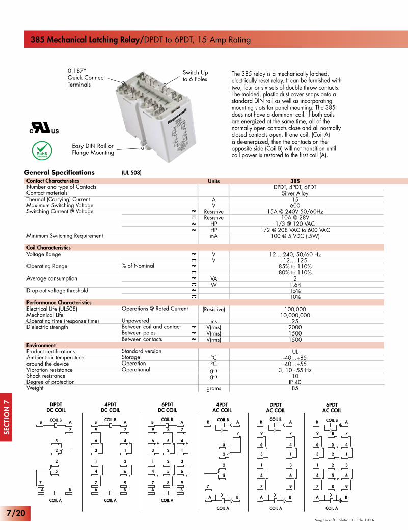
385 Mechanical Latching Relay/DPDT to 6PDT, 15 Amp Rating
Easy DIN Rail or Flange Mounting
Switch Up to 6 Poles
0.187”Quick ConnectTerminals
The 385 relay is a mechanically latched, electrically reset relay. It can be furnished with two, four or six sets of double throw contacts. The molded, plastic dust cover snaps onto a standard DIN rail as well as incorporating mounting slots for panel mounting. The 385 does not have a dominant coil. If both coils are energized at the same time, all of the normally open contacts close and all normally closed contacts open. If one coil, (Coil A) is de-energized, then the contacts on the opposite side (Coil B) will not transition until coil power is restored to the first coil (A).
Units
AV
ResistiveResistive
HPHPmA
VV
VAW
(Resistive)
msV(rms)V(rms)V(rms)
°C°Cg-ng-n
grams
385DPDT, 4PDT, 6PDT
Silver Alloy15600
15A @ 240V 50/60Hz10A @ 28V
1/3 @ 120 VAC1/2 @ 208 VAC to 600 VAC
100 @ 5 VDC (.5W)
12….240, 50/60 Hz12….125
85% to 110%80% to 110%
21.6415%10%
100,00010,000,000
25200015001500
UL-40…+85-40…+55
3, 10 - 55 Hz10
IP 4085
% of Nominal
Operations @ Rated Current
UnpoweredBetween coil and contactBetween polesBetween contacts
Standard versionStorageOperationOperational
Contact Characteristics Number and type of ContactsContact materialsThermal (Carrying) CurrentMaximum Switching VoltageSwitching Current @ Voltage
Minimum Switching Requirement
Coil CharacteristicsVoltage Range
Operating Range
Average consumption
Drop-out voltage threshold
Performance CharacteristicsElectrical Life (UL508)Mechanical LifeOperating time (response time)Dielectric strength
EnvironmentProduct certificationsAmbient air temperaturearound the deviceVibration resistanceShock resistanceDegree of protectionWeight
7/20

Magnecraf t Solut ion Guide 105A
SEC
TIO
N 7
Magnecraf t Solut ion Guide 105A
Part Number Builder
B A
A
6
9
3
4
1
5
8
2
5
2
7 8
4
7
1
6
3
B
9
A
B
3.04 (77.22)
2.7 (69.01)
1.49(37.85)
1.67(42.42)
2.39(60.8)
1.36(33.02)
1.38 (34.9)
0.187 QUICKCONNECTS
BOLD-FACED PART NUMBERS ARE NORMALLY STOCKED
www.magnecraft.com 847-441-2540
385Series385
XBXContact Configuration
DPDT = XBX4PDT = XDX6PDT = XFX
FTemperature Class130° C = None
155° C = F
– 240ACoil Voltage
VAC = 6 - 240AVDC = 6 - 125D
Coil Resistance
30/30 Ohms180/180 Ohms
3,800/3,800 Ohms16,000/16,000 Ohms
85/85 Ohms340/340 Ohms
1,360/1,360 Ohms9,000/9,000 Ohms
Part NumberDPDT
385XBX-12A385XBX-24A385XBX-120A
385XBX-240A
385XBX-12D385XBX-24D385XBX-48D
385XBX-110/125D
Nominal Voltage
AC Operated (Single Coil)12 VAC 50/60 HZ24 VAC 50/60 HZ120 VAC 50/60 HZ240 VAC 50/60 HZ
DC Operated12 VDC24 VDC48 VDC
110-125 VDC
Part Number4PDT
385XDX-12A385XDX-24A
385XDX-120A385XDX-240A
385XDX-12D385XDX-24D385XDX-48D
385XDX-110/125D
Part Number6PDT
385XFX-12A385XFX-24A385XFX-120A385XFX-240A
385XFX-12D385XFX-24D385XFX-48D
385XFX-110/125D
Standard Part Numbers
7/21

SEC
TIO
N 7
www.magnecraft.com 847-441-2540
7 Cross Reference GuideS e c t i o n
Magnecraf t Solut ion Guide 105A
www.magnecraft.com 847-441-2540Magnecraf t Solut ion Guide 105A
Midtex619-11B200619-11C200619-11D200619-11F200
ATC DiversifiedARA120ABA
ARA120ADA
Supercedes MagnecraftW250AML2CPX-8W250AML2CPX-9W250AML2CPX-10W250ML2CPX-6W250ML2CPX-7W250ML2CPX-8
Supercedes Magnecraft285XBXC-120A / 388AMLCPX-9285XBXC-240A / 388AMLCPX-10285XBXC-12D / 388MLCPX-6285XBXC-24D / 388MLCPX-7285XBXCD-12D / 388ML2CPX-6285XBXCD-24D / 388ML2CPX-7285XBXCD-110D / 388ML2CPX-8
Potter & BrumfieldKB-17AG-120 or KUB-17A15-120 KB-17DG-12 or KUB-17D15-12 KB-17DG-24 or KUB-17D15-24
Magnecraft711XBXC-12D711XBXC-24D711XBXC-48D711XBXC-110D
Magnecraft712XAXC712XBXC712XBXCK712XBXCK1
Magnecraft755XBXC-24A755XBXC-120A755XBXC-240A755XBXCD-12D755XBXCD-24D755XBXCD-110D
Magnecraft785XBXC-120A785XBXC-240A785XBXC-12D785XBXC-24D785XBXCD-12D785XBXCD-24D785XBXCD-110D
Magnecraft385XDX-120A385XDX-12D385XDX-24D
Potter & BrumfieldKUR-11D15-12KUR-11D15-24KUR-11D15-48KUR-11D15-110
Time Mark261ST-120261DXT-120
261DT-120
IdecRR2KP-U-AC24RR2KP-U-AC120RR2KP-U-AC240RR2KP-U-DC12RR2KP-U-DC24RR2KP-U-DC110
Potter & BrumfieldKUL11A15S-120KUL11A15S-240KUL11D15S-12KUL11D15S-24KUL11D15D-12KUL11D15D-24KUL11D15D-110
SSACARP41SARP43S ARP42S
RelecoC3-R20/AC24VC3-R20/AC120VC3-R20/AC240V
RelecoC5-R20/AC120VC5-R20/AC240VC5-R20/DC12VC5-R20/DC24V
7/22

www.magnecraft.com 847-441-2540Magnecraf t Solut ion Guide 105A
SEC
TIO
N 7
www.magnecraft.com 847-441-2540Magnecraf t Solut ion Guide 105A
NTER50-11A10-120R50-11A10-240R50-11D10-12R50-11D10-24R50-11D10-12CR50-11D10-24CR50-11D10-110C
Deltrol20525-8420525-8520531-8120531-8220537-8120537-8220537-84
7/23

SEC
TIO
N 7
Magnecraf t Solut ion Guide 105A
www.magnecraft.com 847-441-2540NOTES:
7/24
Recommended