sitrans f
SITRANS F M MAGFLOElectromagnetic FlowmetersExplore the Siemens Solution
s

Cost effective solution
The MAG 5000 transmitter and MAG 5100 W sensor are the perfectmatch for a cost effective solution.
• One solution for all your water & wastewater applications
• No moving parts ensures longterm performance
• Hard rubber elastomer liner guarantees consistent accuracy
• Highly resistant to a wide rangeof chemicals used in treatmentplants
• Increased low-flow measurementfor leak detection
• Sensor suitable for burial andconstant flooding
• Drinking water approvals• Complies with most international
standards and agency approvals• Built-in ground electrodes
eliminate grounding rings
Process optimisationMAG 6000 with the USM II add-on communication platformmakes it easy to integrate MAGFLO information into process applications.
Realize the full benefits of automation • Optimise management and
process control• Ensure correct dosing and
product quality• Minimise process time
and consumption of high-costchemicals
Water and WastewaterMAGFLO for water processes
MAG 6000 I(Ex d)
MAG 1100 MAG 6000electrode cleanings
Hazardous areasMAG 6000 I (Ex d) available for use inhazardous areas.
Chemical dosingMAG 1100 for optimi-sing the treatment process.
Electrode CleaningAutomatic self-cleaningof extreme deposits onthe sensor electrodes.
The Siemens product rangeprovides sensors from 2 mmup to 2000 mm and from 1/12’’up to 78’’
In-situ MAGFLO VerificationYour guarantee for continuousaccurate measurement
• Correct revenue metering• Confidence in process and
product quality• As hand-over of new
installations to ensure correct installation
• ISO 9000 and ISO 14001
SITRANS F flowmetersSITRANS F M
MAGFLO MAG 5100 W
4/51Siemens FI 01 · 2005
4
■ Overview
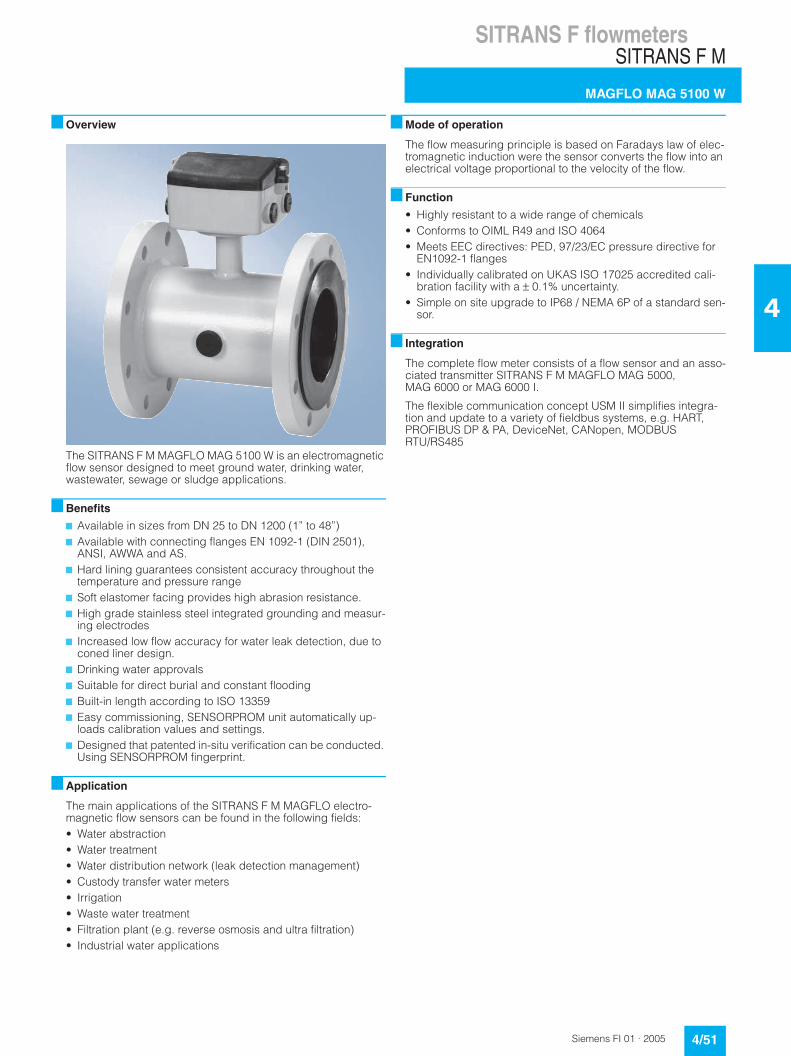
The SITRANS F M MAGFLO MAG 5100 W is an electromagnetic flow sensor designed to meet ground water, drinking water, wastewater, sewage or sludge applications.
■ Benefits
7 Available in sizes from DN 25 to DN 1200 (1” to 48”)7 Available with connecting flanges EN 1092-1 (DIN 2501),
ANSI, AWWA and AS.7 Hard lining guarantees consistent accuracy throughout the
temperature and pressure range7 Soft elastomer facing provides high abrasion resistance.7 High grade stainless steel integrated grounding and measur-
ing electrodes7 Increased low flow accuracy for water leak detection, due to
coned liner design.7 Drinking water approvals7 Suitable for direct burial and constant flooding7 Built-in length according to ISO 133597 Easy commissioning, SENSORPROM unit automatically up-
loads calibration values and settings.7 Designed that patented in-situ verification can be conducted.
Using SENSORPROM fingerprint.
■ Application
The main applications of the SITRANS F M MAGFLO electro-magnetic flow sensors can be found in the following fields:• Water abstraction• Water treatment• Water distribution network (leak detection management)• Custody transfer water meters• Irrigation• Waste water treatment• Filtration plant (e.g. reverse osmosis and ultra filtration)• Industrial water applications
■ Mode of operation
The flow measuring principle is based on Faradays law of elec-tromagnetic induction were the sensor converts the flow into an electrical voltage proportional to the velocity of the flow.
■ Function
• Highly resistant to a wide range of chemicals• Conforms to OIML R49 and ISO 4064• Meets EEC directives: PED, 97/23/EC pressure directive for
EN1092-1 flanges• Individually calibrated on UKAS ISO 17025 accredited cali-
bration facility with a ± 0.1% uncertainty.• Simple on site upgrade to IP68 / NEMA 6P of a standard sen-
sor.
■ Integration
The complete flow meter consists of a flow sensor and an asso-ciated transmitter SITRANS F M MAGFLO MAG 5000, MAG 6000 or MAG 6000 I.
The flexible communication concept USM II simplifies integra-tion and update to a variety of fieldbus systems, e.g. HART, PROFIBUS DP & PA, DeviceNet, CANopen, MODBUS RTU/RS485
SITRANS F flowmetersSITRANS F M
MAGFLO MAG 5100 W
4/52 Siemens FI 01 · 2005
4
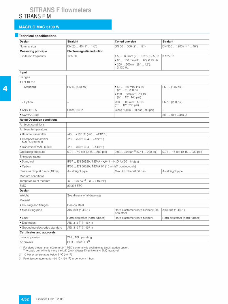
■ Technical specifications
1) For sizes greater than 600 mm (24”) PED conformity is available as a cost added option. The basic unit will only carry the LVD (Low Voltage Directive) and EMC approval.
2) 10 bar at temperature below 5 °C (40 °F)
3) Peak temperature up to +90 °C (194 °F) in periods < 1 hour
Design Straight Coned one size Straight
Nominal size DN 25 ... 40 (1” ... 1½”) DN 50 ... 300 (2” ... 12”) DN 350 ... 1200 (14” ... 48”)
Measuring principle Electromagnetic induction
Excitation frequency 12.5 Hz • 50 ... 60 mm (2” ... 2½“): 12.5 Hz• 80 ... 150 mm (3” ... 6“): 6.25 Hz• 200 ... 300 mm (8” ... 12“):
3.125 Hz
3.125 Hz
Input
Flanges
• EN 1092-1
- Standard PN 40 (580 psi) • 50 ... 150 mm: PN 16(2“ ... 6“: 230 psi)
• 200 ... 300 mm: PN 10(8“ ... 12“: 145 psi)
PN 10 (145 psi)
- Option -- 200 ... 300 mm: PN 16(8“ ... 12“: 230 psi)
PN 16 (230 psi)
• ANSI B16.5 Class 150 lb Class 150 lb ~20 bar (290 psi) --
• AWWA C-207 -- -- 28” ... 48”: Class D
Rated Operation conditions
Ambient conditions
Ambient temperature
• Remote transmitter -40 ... +100 °C (-40 ... +212 °F)
• Compact transmitter MAG 5000/6000
-20 ... +50 °C (-4 ... +122 °F)
• Transmitter MAG 6000 I -20 ... +60 °C (-4 ... +140 °F)
Operating pressure 0.01 ... 40 bar (0.15 ... 580 psi) 0.03 ... 20 bar 2) (0.44 ... 290 psi) 0.01 ... 16 bar (0.15 ... 232 psi)
Enclosure rating
• Standard IP67 to EN 60529 / NEMA 4X/6 (1 mH2O for 30 minutes)
• Option IP68 to EN 60529 / NEMA 6P (10 mH2O continuously)
Pressure drop at 3 m/s (10 ft/s) As straight pipe Max. 25 mbar (0.36 psi) As straight pipe
Medium conditions
Temperature of medium -5 ... +70 °C 3) (23 ... +160 °F)
EMC 89/336 EEC
Design
Weight See dimensional drawings
Material
• Housing and flanges Carbon steel
• Measuring pipe AISI 304 (1.4301) Hard elastomer (hard rubber)/Car-bon steel
AISI 304 (1.4301)
• Liner Hard elastomer (hard rubber) Hard elastomer (hard rubber) Hard elastomer (hard rubber)
• Electrodes AISI 316 Ti (1.4571)
• Grounding electrodes standard AISI 316 Ti (1.4571)
Certificates and approvals
Liner approvals WRc, NSF pending
Approvals PED – 97/23 EC1)
SITRANS F flowmetersSITRANS F M
MAGFLO MAG 5100 W
4/53Siemens FI 01 · 2005
4
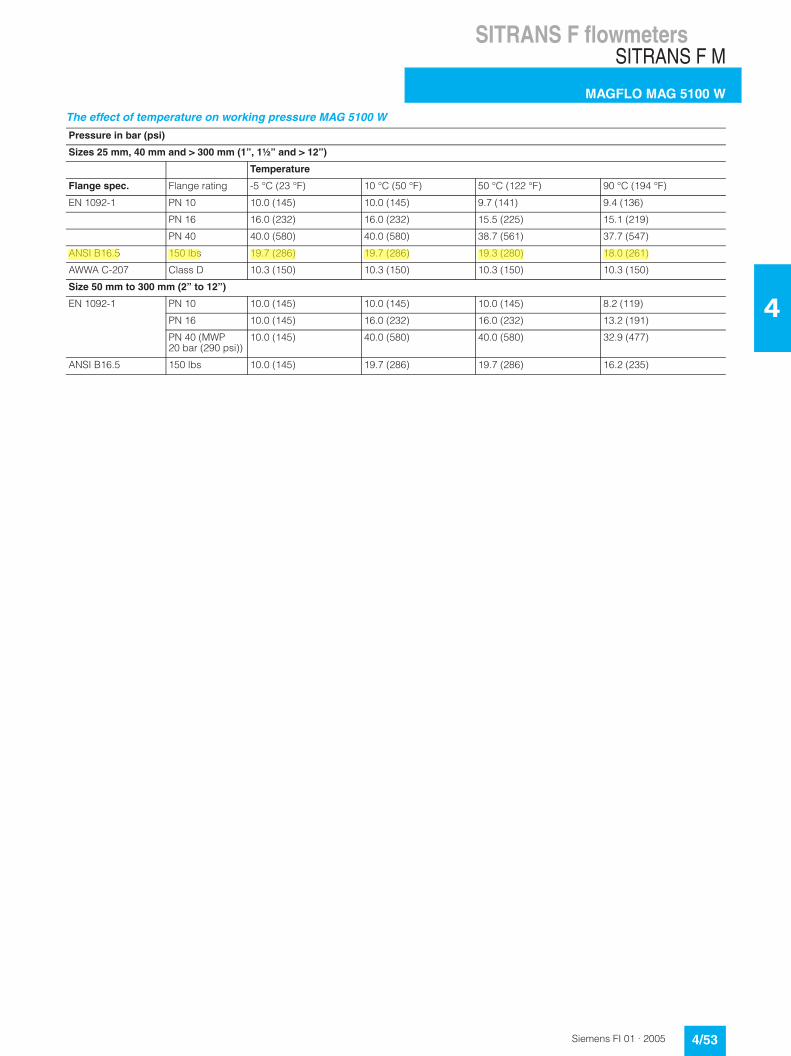
The effect of temperature on working pressure MAG 5100 W
Pressure in bar (psi)
Sizes 25 mm, 40 mm and > 300 mm (1”, 1½” and > 12”)
Temperature
Flange spec. Flange rating -5 °C (23 °F) 10 °C (50 °F) 50 °C (122 °F) 90 °C (194 °F)
EN 1092-1 PN 10 10.0 (145) 10.0 (145) 9.7 (141) 9.4 (136)
PN 16 16.0 (232) 16.0 (232) 15.5 (225) 15.1 (219)
PN 40 40.0 (580) 40.0 (580) 38.7 (561) 37.7 (547)
ANSI B16.5 150 lbs 19.7 (286) 19.7 (286) 19.3 (280) 18.0 (261)
AWWA C-207 Class D 10.3 (150) 10.3 (150) 10.3 (150) 10.3 (150)
Size 50 mm to 300 mm (2” to 12”)
EN 1092-1 PN 10 10.0 (145) 10.0 (145) 10.0 (145) 8.2 (119)
PN 16 10.0 (145) 16.0 (232) 16.0 (232) 13.2 (191)
PN 40 (MWP 20 bar (290 psi))
10.0 (145) 40.0 (580) 40.0 (580) 32.9 (477)
ANSI B16.5 150 lbs 10.0 (145) 19.7 (286) 19.7 (286) 16.2 (235)
SITRANS F flowmetersSITRANS F M
MAGFLO MAG 5100 W
4/54 Siemens FI 01 · 2005
4
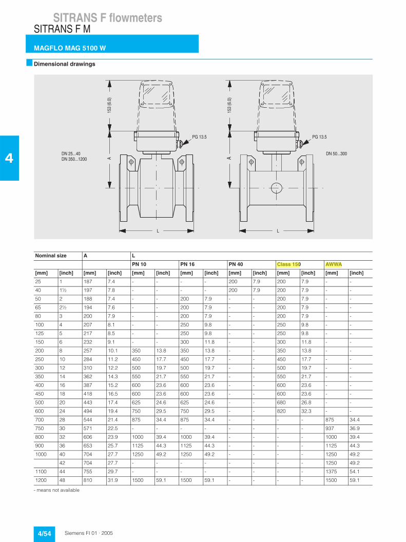
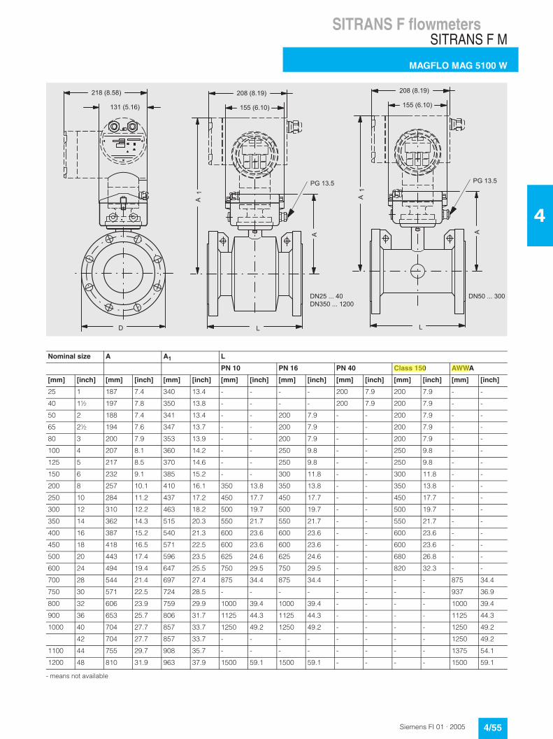
■ Dimensional drawings
- means not available
8:�����
6��
����
���
96
9
8:�����
����
����
�
*?������&�*?�����������
*?���������
Nominal size A L
PN 10 PN 16 PN 40 Class 150 AWWA
[mm] [inch] [mm] [inch] [mm] [inch] [mm] [inch] [mm] [inch] [mm] [inch] [mm] [inch]
25 1 187 7.4 - - - - 200 7.9 200 7.9 - -
40 1½ 197 7.8 - - - - 200 7.9 200 7.9 - -
50 2 188 7.4 - - 200 7.9 - - 200 7.9 - -
65 2½ 194 7.6 - - 200 7.9 - - 200 7.9 - -
80 3 200 7.9 - - 200 7.9 - - 200 7.9 - -
100 4 207 8.1 - - 250 9.8 - - 250 9.8 - -
125 5 217 8.5 - - 250 9.8 - - 250 9.8 - -
150 6 232 9.1 - - 300 11.8 - - 300 11.8 - -
200 8 257 10.1 350 13.8 350 13.8 - - 350 13.8 - -
250 10 284 11.2 450 17.7 450 17.7 - - 450 17.7 - -
300 12 310 12.2 500 19.7 500 19.7 - - 500 19.7 - -
350 14 362 14.3 550 21.7 550 21.7 - - 550 21.7 - -
400 16 387 15.2 600 23.6 600 23.6 - - 600 23.6 - -
450 18 418 16.5 600 23.6 600 23.6 - - 600 23.6 - -
500 20 443 17.4 625 24.6 625 24.6 - - 680 26.8 - -
600 24 494 19.4 750 29.5 750 29.5 - - 820 32.3 - -
700 28 544 21.4 875 34.4 875 34.4 - - - - 875 34.4
750 30 571 22.5 - - - - - - - - 937 36.9
800 32 606 23.9 1000 39.4 1000 39.4 - - - - 1000 39.4
900 36 653 25.7 1125 44.3 1125 44.3 - - - - 1125 44.3
1000 40 704 27.7 1250 49.2 1250 49.2 - - - - 1250 49.2
42 704 27.7 - - - - - - - - 1250 49.2
1100 44 755 29.7 - - - - - - - - 1375 54.1
1200 48 810 31.9 1500 59.1 1500 59.1 - - - - 1500 59.1
SITRANS F flowmetersSITRANS F M
MAGFLO MAG 5100 W
4/55Siemens FI 01 · 2005
4
- means not available
A
L L
PG 13.5
1
218 (8.58)
131 (5.16)
D
155 (6.10)
208 (8.19) 208 (8.19)
155 (6.10)
A
1A
A
PG 13.5
Nominal size A A1 L
PN 10 PN 16 PN 40 Class 150 AWWA
[mm] [inch] [mm] [inch] [mm] [inch] [mm] [inch] [mm] [inch] [mm] [inch] [mm] [inch] [mm] [inch]
25 1 187 7.4 340 13.4 - - - - 200 7.9 200 7.9 - -
40 1½ 197 7.8 350 13.8 - - - - 200 7.9 200 7.9 - -
50 2 188 7.4 341 13.4 - - 200 7.9 - - 200 7.9 - -
65 2½ 194 7.6 347 13.7 - - 200 7.9 - - 200 7.9 - -
80 3 200 7.9 353 13.9 - - 200 7.9 - - 200 7.9 - -
100 4 207 8.1 360 14.2 - - 250 9.8 - - 250 9.8 - -
125 5 217 8.5 370 14.6 - - 250 9.8 - - 250 9.8 - -
150 6 232 9.1 385 15.2 - - 300 11.8 - - 300 11.8 - -
200 8 257 10.1 410 16.1 350 13.8 350 13.8 - - 350 13.8 - -
250 10 284 11.2 437 17.2 450 17.7 450 17.7 - - 450 17.7 - -
300 12 310 12.2 463 18.2 500 19.7 500 19.7 - - 500 19.7 - -
350 14 362 14.3 515 20.3 550 21.7 550 21.7 - - 550 21.7 - -
400 16 387 15.2 540 21.3 600 23.6 600 23.6 - - 600 23.6 - -
450 18 418 16.5 571 22.5 600 23.6 600 23.6 - - 600 23.6 - -
500 20 443 17.4 596 23.5 625 24.6 625 24.6 - - 680 26.8 - -
600 24 494 19.4 647 25.5 750 29.5 750 29.5 - - 820 32.3 - -
700 28 544 21.4 697 27.4 875 34.4 875 34.4 - - - - 875 34.4
750 30 571 22.5 724 28.5 - - - - - - - - 937 36.9
800 32 606 23.9 759 29.9 1000 39.4 1000 39.4 - - - - 1000 39.4
900 36 653 25.7 806 31.7 1125 44.3 1125 44.3 - - - - 1125 44.3
1000 40 704 27.7 857 33.7 1250 49.2 1250 49.2 - - - - 1250 49.2
42 704 27.7 857 33.7 - - - - - - - - 1250 49.2
1100 44 755 29.7 908 35.7 - - - - - - - - 1375 54.1
1200 48 810 31.9 963 37.9 1500 59.1 1500 59.1 - - - - 1500 59.1
SITRANS F flowmetersSITRANS F M
MAGFLO MAG 5100 W
4/56 Siemens FI 01 · 2005
4
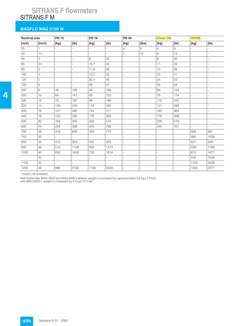
- means not available
With transmitter MAG 5000 and MAG 6000 installed, weight is increased by approximately 0.8 kg (1.8 lbs), with MAG 6000 I, weight is increased by 5.5 kg (12.1 lb).
Nominal size PN 10 PN 16 PN 40 Class 150 AWWA
[mm] [inch] [kg] [lb] [kg] [lb] [kg] [lbs] [kg] [lb] [kg] [lb]
25 1 - - - - 4 9 4 9 - -
40 1½ - - - - 7 15 6 13 - -
50 2 - - 9 20 - - 8 20 - -
65 2½ - - 10.7 24 - - 11 24 - -
80 3 - - 11.6 26 - - 13 28 - -
100 4 - - 15.2 33 - - 19 41 - -
125 5 - - 20.4 45 - - 24 52 - -
150 6 - - 26 57 - - 29 64 - -
200 8 48 106 48 106 - - 56 124 - -
250 10 64 141 69 152 - - 79 174 - -
300 12 76 167 86 189 - - 110 243 - -
350 14 100 220 116 255 - - 131 289 - -
400 16 127 280 144 317 - - 165 364 - -
450 18 152 335 178 393 - - 176 388 - -
500 20 184 405 232 512 - - 235 518 - -
600 24 258 568 343 736 - - 345 761 - -
700 28 315 693 350 772 - - - - 309 681
750 30 - - - - - - - - 480 1058
800 32 410 904 442 975 - - - - 421 928
900 36 512 1129 550 1213 - - - - 539 1188
1000 40 650 1433 732 1614 - - - - 670 1477
42 - - - - - - - - 700 1544
1100 44 - - - - - - - - 1100 2426
1200 48 990 2183 1106 2439 - - - - 1030 2271
SITRANS F flowmetersSITRANS F M
MAGFLO MAG 5100 W
4/57Siemens FI 01 · 2005
4
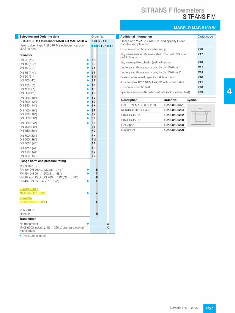
Selection and Ordering data Order No.
SITRANS F M Flowsensor MAGFLO MAG 5100 WHard rubber liner, AISI 316 Ti electrodes, carbon steel flanges
7 M E 6 5 1 0 -
777 1 1 - 1 7A 0
Diameter
DN 25 (1“) } 2 DDN 40 (1½“) } 2 RDN 50 (2“) } 2 Y
DN 65 (2½“) } 3 FDN 80 (3“) } 3 MDN 100 (4“) } 3 T
DN 125 (5“) } 4 BDN 150 (6“) } 4 HDN 200 (8“) } 4 P
DN 250 (10“) } 4 VDN 300 (12“) } 5 DDN 350 (14“) } 5 K
DN 400 (16“) } 5 RDN 450 (18“) } 5 YDN 500 (20“) } 6 F
DN 600 (24“) } 6 PDN 700 (28“) 6 YDN 750 (30“) 7 D
DN 800 (32“) 7 HDN 900 (36“) 7 MDN 1000 (40“) 7 R
DN 1050 (42“) 7 UDN 1100 (44“) 7 VDN 1200 (48“) 8 B
Flange norm and pressure rating
to EN 1092-1PN 10 (DN 200 ... 1200/8“ ... 48“) } BPN 16 (DN 50 ... 1200/2“ ... 48“) } CPN 16, non PED (DN 700 ... 1200/28“ ... 48“) DPN 40 (DN 25 ... 40/1“ ... 1½“) } F
to ANSI B16.5class 150 (1“ ... 24“) } J
to AWWAC-207 (28“ ... 1200“) L
to AS 4087class 14 N
Transmitter
No transmitter } AMAG 6000 industry, 18 ... 220 V, standard (no com-munication)
C
} Available ex stock.
Additional information Order code
Please add “-Z“ to Order No. and specify Order code(s) and plain text.
Customer specific converter setup Y20
Tag name made, stainless steel fixed with SS wire (add plain text)
Y17
Tag name plate, plastic (self adhesive) Y18
Factory certificate according to EN 10204-2.1 C15
Factory certificate according to EN 10204-2.2 C14
Power cable wired, specify cable order no. Y40
Junction box IP68 NEMA 4X/6P with wired cable Y41
Customer specific test Y90
Special version with order no/date (add desired text) Y99
Description Order No. Symbol
HART (for MAG 6000 I/Ex) FDK:085U0321
MODBUS RTU/RS485 FDK:085U0234
PROFIBUS PA FDK:085U0232
PROFIBUS DP FDK:085U0230
CANopen FDK:085U0228
DeviceNet FDK:085U0229
MAGFLO� Product selection guidelines
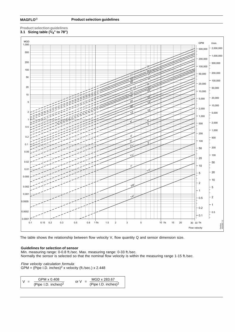
Product selection guidelines3.1 Sizing table (1/4" to 78")
The table shows the relationship between flow velocity V, flow quantity Q and sensor dimension size.
Guidelines for selection of sensorMin. measuring range: 0-0.8 ft./sec. Max. measuring range: 0-33 ft./sec.Normally the sensor is selected so that the nominal flow velocity is within the measuring range 1-15 ft./sec.
Flow velocity calculation formula:GPM = (Pipe I.D. inches)2 x velocity (ft./sec.) x 2.448
V =GPM x 0.408
(Pipe I.D. inches)2or V =
(Pipe I.D. inches)2 MGD x 283.67

The Transmitter ProgramWhat’s right for you?
MAG 5000 and MAG 6000For high performance, easy operation and reducedmaintenance.MAG 5000 is the truly robust solu-tion for all-around applications. MAG 6000 is for the more deman-ding applications where higheraccuracy and greater functionalityis required.
MAG 6000 IndustryThis transmitter is designed for the special demands in the processindustry. The robust, full-metalhousing provides superb protec-tion, even in the harshest industrialenvironments. Full input and out-put functionality is given even inthe ATEX EEx d version.
Guaranteed Performance• Compact or Remote Installation• Superior signal resolution for
optimized turn-down ratio• Digital Signal Processing with
unlimited possibilities• User configurable operation
menu with password protection
• Multiple functional output for process control
• Self-diagnostics for error detection and logging
• Batch control• Multi-lingual display and
keypad • Custody Transfer Approved • Electrode cleaning accessory
option
SENSORPROMEach flow meter has its own identi-ty stored in the SENSORPROM.
The information consists of:• Calibration data• "Fingerprint" – magnetism
properties• User setup and programming
data
The individual calibration and fin-gerprint data are pre-programmedat the factory, whereas the setupdata are customer-specific. Thisunique combination ensures a costeffective, easy and error-free instal-lation.
"Plug & Play" Communication ModulesUSM II (Universal Signal Module) is "Plug & Play" at itsvery best. It makes flowmeter networking installationand configuration easy.
And it is compatible with virtually every communicationstandard used today, including PROFIBUS PA/DP, HART, Modbus RTU, DeviceNet and CANopen.
Transmitter MAG 5000 MAG 6000 MAG 6000 I MAG 6000 I (Ex d)
Enclosure IP67 / NEMA 4X or IP20/66 / NEMA 2/4 Polyamid IP67 / NEMA 6 die-cast aluminium
Max measuring Error 0.50 % of rate 0.25 % of rate
Display 3 line alpha numeric LCD with back light
Inputs & outputs 1 digital input, 1 current output, 1 pulse/frequency output, 1 relay output
Communication HART HART; Profibus PA/DP; Modbus RTU; DeviceNet; CANopen HART; Profibus PA
Batch function No Yes Yes Yes
Power Supply 12 – 24 V AC/DC or 115 – 230 V AC 18 – 90 DC or 115-230 AC 24 V DC or 115 – 230 V AC
Approvals CE; ULc; C-Tick ATEX EEx d e [ia] ia IIB T6
FM Class 1, Div 2 FM Class 1, Div 2
Custody Transfer Cold Water Cold Water, Hot Water,
Approval Other Liquids
MAGFLO�
Spe
cific
atio
ns
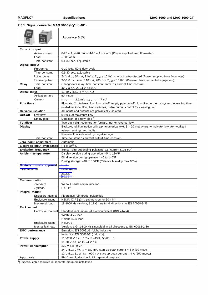
Current outputActive current 0-20 mA, 4-20 mA or 4-20 mA + alarm (Power supplied from flowmeter)Load �800 ohmTime constant 0.1-30 sec. adjustable
Digital outputFrequency 0-10 kHz, 50% duty cycleTime constant 0.1-30 sec. adjustableActive pulse 24 V d.c., 30 mA,�1 K� ��Rload ��10 K�, short-circuit-protected (Power supplied from flowmeter)Passive pulse 3-30 V d.c., max. 110 mA,�200 � ��Rload ��10 K� (Powered from connected equipment)
Relay Time constant Changeover relay, time constant same as current time constantLoad 42 V a.c./2 A, 24 V d.c./1A
Digital input 11-30 V d.c., Ri = 4.4 K�Activation time 50 msec.Current I11 V d.c. = 2.5 mA, I30 V d.c. = 7 mA
Functions Flowrate, 2 totalizers, low flow cut-off, empty pipe cut-off, flow direction, error system, operating time,uni/bidirectional flow, limit switches, pulse output, control for cleaning unit
Galvanic isolation All inputs and outputs are galvanically isolatedCut-off Low flow 0-9.9% of maximum flow
Empty pipe Detection of empty pipe 1)Totalizer Two eight-digit counters for forward, net or reverse flowDisplay Background illumination with alphanumerical text, 3 × 20 characters to indicate flowrate, totalized
values, settings and faultsReverse flow indicated by negative sign
Time constant Time constant as current output time constantZero point adjustment AutomaticElectrode input impedance �1 x 10¹⁴ �Excitation frequency Sensor size depending pulsating d.c. current (125 mA)Ambient temperature Display version during operation:��5 to 120�F
Blind version during operation:��5 to 140�FDuring storage:��40 to 160�F (Relative humidity max 95%)
Custody transfer approval PTB MAG 5000 CT (cold water)
CommunicationStandard Without serial communicationOptional HART�
Integral mountEnclosure material Fiberglass-reinforced polyamideEnclosure rating NEMA 4X / 6 (3 ft. submersion for 30 min)Mecanical load 18-1000 Hz random, 3.17 G rms in all directions to EN 60068-2-36
Rack mountEnclosure material Standard rack mount of aluminum/steel (DIN 41494)
Width: 4.75 inchHeight: 5.25 inch
Enclosure rating NEMA 2Mechanical load Version: 1 G, 1-800 Hz sinusoidal in all directions to EN 60068-2-36
EMC performance Emission: EN 50081-1 (Light industry)Immunity: EN 50082-2 (Industry)
Power supply 115-230 V a.c. +10% to �15%, 50-60 Hz11-30 V d.c. or 11-24 V a.c.
Power consumption 230 V a.c.: 9 VA24 V d.c.: 9 W, IN = 380 mA, start-up peak current = 8 A (30 msec.)12 V d.c.: 11 W, IN = 920 mA start-up peak current = 4 A (250 msec.)
Approvals FM Class 1, division 2, ULc general purpose1) Special cable required in separate mounted installation
Specification s MAG 5000 and MAG 5000 CT
2.5.1 Signal converter MAG 5000 (1/4" to 48 " )
Accuracy 0.5%
6.22199.19
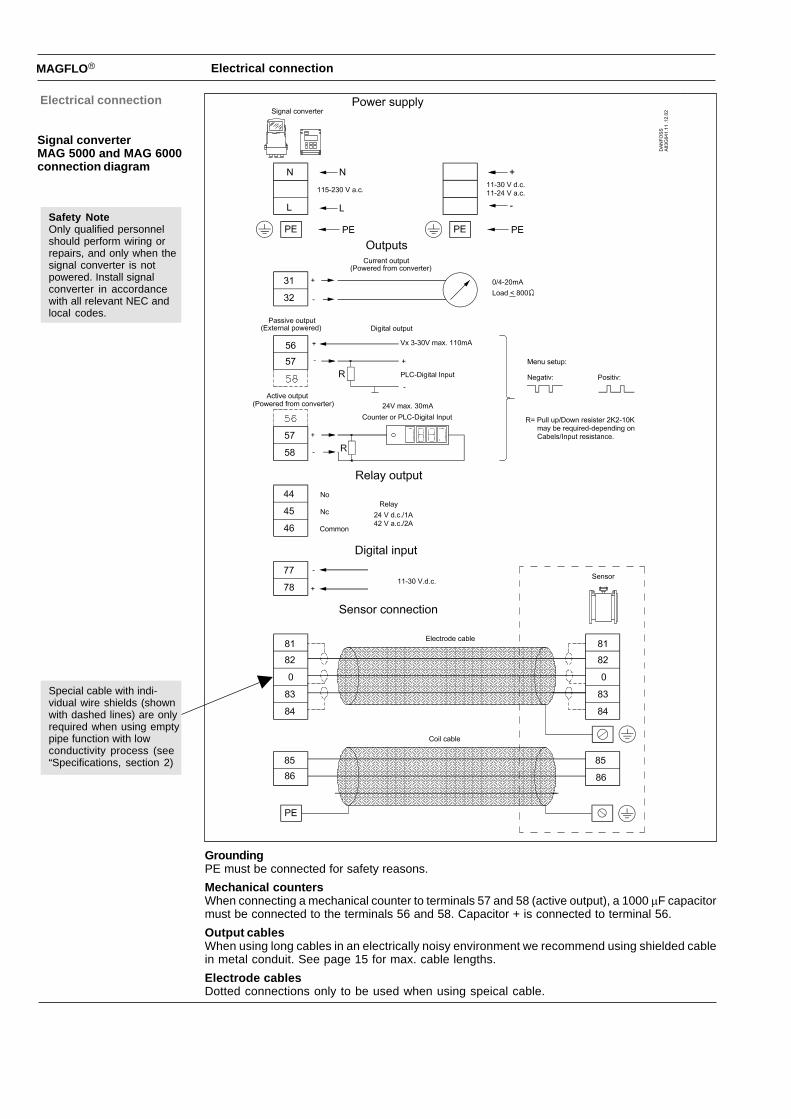
MAGFLO� Electrical connection
Electrical connection
Signal converterMAG 5000 and MAG 6000connection diagram
GroundingPE must be connected for safety reasons.
Mechanical countersWhen connecting a mechanical counter to terminals 57 and 58 (active output), a 1000 �F capacitormust be connected to the terminals 56 and 58. Capacitor + is connected to terminal 56.
Output cablesWhen using long cables in an electrically noisy environment we recommend using shielded cablein metal conduit. See page 15 for max. cable lengths.
Electrode cablesDotted connections only to be used when using speical cable.
Special cable with indi-vidual wire shields (shownwith dashed lines) are onlyrequired when using emptypipe function with lowconductivity process (see“Specifications, section 2)
Safety NoteOnly qualified personnelshould perform wiring orrepairs, and only when thesignal converter is notpowered. Install signalconverter in accordancewith all relevant NEC andlocal codes.
MAGFLO� Project guidance
Pro
ject
gui
danc
e
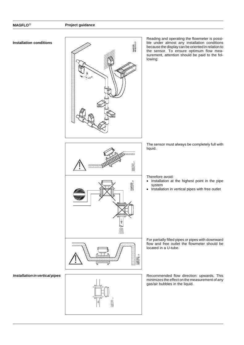
Installation conditionsReading and operating the flowmeter is possi-ble under almost any installation conditionsbecause the display can be oriented in relation tothe sensor. To ensure optimum flow mea-surement, attention should be paid to the fol-lowing:
The sensor must always be completely full withliquid.
Therefore avoid:� Installation at the highest point in the pipe
system� Installation in vertical pipes with free outlet
For partially filled pipes or pipes with downwardflow and free outlet the flowmeter should belocated in a U-tube.
Recommended flow direction: upwards. Thisminimizes the effect on the measurement of anygas/air bubbles in the liquid.
Installation in vertical pipes
MAGFLO Project guidance
Pro
ject
gui
danc
e
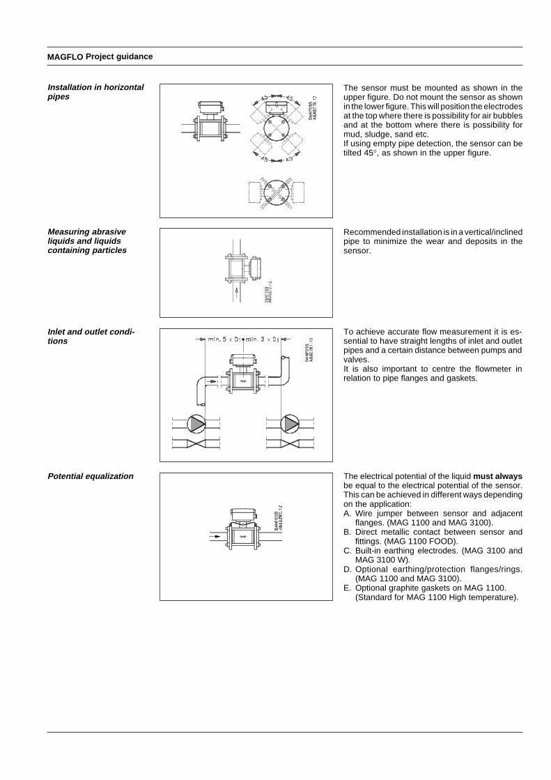
The sensor must be mounted as shown in theupper figure. Do not mount the sensor as shownin the lower figure. This will position the electrodesat the top where there is possibility for air bubblesand at the bottom where there is possibility formud, sludge, sand etc.If using empty pipe detection, the sensor can betilted 45�, as shown in the upper figure.
Recommended installation is in a vertical/inclinedpipe to minimize the wear and deposits in thesensor.
To achieve accurate flow measurement it is es-sential to have straight lengths of inlet and outletpipes and a certain distance between pumps andvalves.It is also important to centre the flowmeter inrelation to pipe flanges and gaskets.
The electrical potential of the liquid must alwaysbe equal to the electrical potential of the sensor.This can be achieved in different ways dependingon the application:A. Wire jumper between sensor and adjacent
flanges. (MAG 1100 and MAG 3100).B. Direct metallic contact between sensor and
fittings. (MAG 1100 FOOD).C. Built-in earthing electrodes. (MAG 3100 and
MAG 3100 W).D. Optional earthing/protection flanges/rings.
(MAG 1100 and MAG 3100).E. Optional graphite gaskets on MAG 1100.
(Standard for MAG 1100 High temperature).
Installation in horizontalpipes
Measuring abrasiveliquids and liquidscontaining particles
Inlet and outlet condi-tions
Potential equalization
MAGFLO� Project guidance
Pro
ject
gui
danc
e
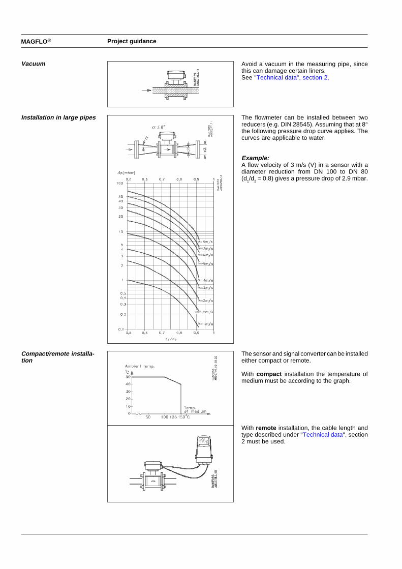
Avoid a vacuum in the measuring pipe, sincethis can damage certain liners.See "Technical data", section 2.
The flowmeter can be installed between tworeducers (e.g. DIN 28545). Assuming that at 8�the following pressure drop curve applies. Thecurves are applicable to water.
Example:A flow velocity of 3 m/s (V) in a sensor with adiameter reduction from DN 100 to DN 80(d1/d2 = 0.8) gives a pressure drop of 2.9 mbar.
The sensor and signal converter can be installedeither compact or remote.
With compac t installation the temperature ofmedium must be according to the graph.
With remot e installation, the cable length andtype described under "Technical data", section2 must be used.
Vacuum
Installation in large pipes
Compact/remote installa-tion
MAGFLO�
conv
.
Installation of signal converter
Installation of signalconverter
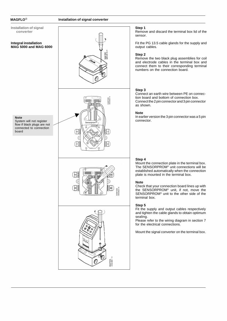
Integral installationMAG 5000 and MAG 6000
Step 1Remove and discard the terminal box lid of thesensor.
Fit the PG 13.5 cable glands for the supply andoutput cables.
Step 2Remove the two black plug assemblies for coiland electrode cables in the terminal box andconnect them to their corresponding terminalnumbers on the connection board.
Step 3Connect an earth wire between PE on connec-tion board and bottom of connection box.Connect the 2 pin connector and 3 pin connectoras shown.
NoteIn earlier version the 3 pin connector was a 5 pinconnector.
Step 4Mount the connection plate in the terminal box.The SENSORPROM® unit connections will beestablished automatically when the connectionplate is mounted in the terminal box.
NoteCheck that your connection board lines up withthe SENSORPROM® unit, if not, move theSENSORPROM® unit to the other side of theterminal box.
Step 5Fit the supply and output cables respectivelyand tighten the cable glands to obtain optimumsealing.Please refer to the wiring diagram in section 7for the electrical connections.
Mount the signal converter on the terminal box.
NoteSystem will not registerflow if black plugs are notconnected to connectionboard
MAGFLO�
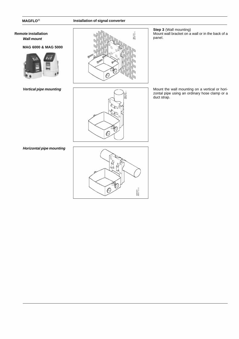
Remote installationWall mount
MAG 6000 & MAG 5000
Step 3 (Wall mounting)Mount wall bracket on a wall or in the back of apanel.
Mount the wall mounting on a vertical or hori-zontal pipe using an ordinary hose clamp or aduct strap.
Vertical pipe mounting
Horizontal pipe mounting
Installation of signal converter
MAGFLO�
conv
.
Installation of signal converter
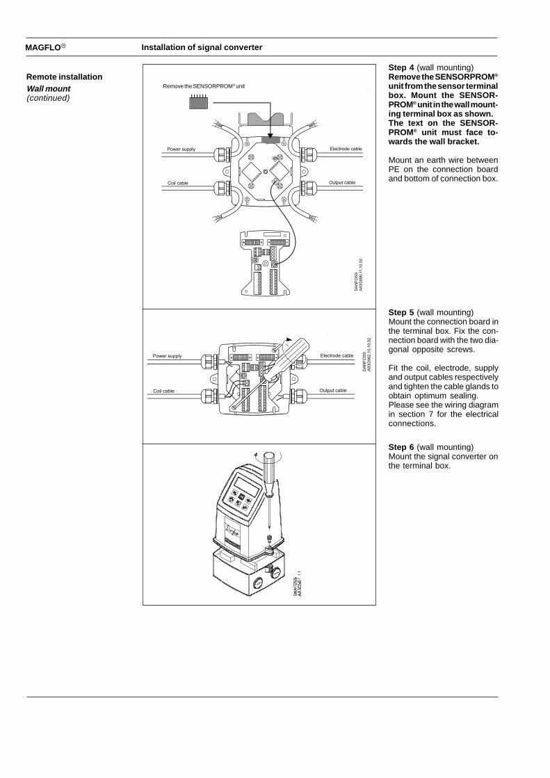
Remote installationWall mount(continued)
Step 4 (wall mounting)Remove the SENSORPROM ®
unit from the sensor terminalbox. Mount the SENSOR-PROM® unit in the wall mount-ing terminal box as shown.The text on the SENSOR-PROM® unit must face to-wards the wall bracket.
Mount an earth wire betweenPE on the connection boardand bottom of connection box.
Step 5 (wall mounting)Mount the connection board inthe terminal box. Fix the con-nection board with the two dia-gonal opposite screws.
Fit the coil, electrode, supplyand output cables respectivelyand tighten the cable glands toobtain optimum sealing.Please see the wiring diagramin section 7 for the electricalconnections.
Step 6 (wall mounting)Mount the signal converter onthe terminal box.
Remove the SENSORPROM® unit
Recommended