1
FINAL PROJECT
MADE A THERMOSTAT WITH A 4 AXIS CNC MACHINING
PROCESS AND TOOLING DESIGN
A Graduation Project Report submitted by
Jony Kartikno
9999156135 / D200090207
In fulfillment of the requirement of
One-year course in Mechanical Engineering Department,
Wuxi Institute of Technology
A part of Undergraduate study in the Automotive Engineering,
Department of Machanical Engineering, Universitas Muhammadiyah Surakarta
Towards the degree of
Bachelor of Engineering (Mechanical)
MECHANICAL ENGINEERING DEPARTMENT
WUXI INSTITUTE OF TECHNOLOGY
WUXI, JIANGSU PROVINCE, P.R. CHINA
TEKNIK OTOMOTIF
FAKULTAS TEKNIK
UNIVERSITAS MUHAMMADIYAH SURAKARTA
2016
2
i

3
CERTIFICATE OF EXCHANGE STUDY PROGRAM
ii

4
iii

1
MADE A THERMOSTAT WITH A 4 AXIS CNC MACHINING PROCESS
AND TOOLING DESIGN
ABSTRACT
Also known as the thermostat thermostat, coolant flow path control valve.
As a thermostat device comprising temperature sensitive components generally,
by expansion or shrink to open, turn off the flow of air, gas or liquid. Its role is
automatically adjusted according to the level of the engine cooling water
temperature of water entering the radiator, change the water cycle range for
adjusting the cooling capacity of the cooling system to ensure the engine is
operating at a suitable temperature range. Thermostat body itself cast aluminum
alloy, five-sided machining body, processing contents, excellent air tightness
requirements of the finished product, the relative processing requirements are
relatively high. Processing thermostat body's need to use modern CNC machine
tools, CNC machine tools development trend of modern high-speed, high-
precision, high reliability, multi-functional, complex, intelligent and open
architecture. The main developments in the research and development of software
and hardware with intelligent full-featured universal open architecture NC device.
CNC machining technology is the basis for automation, CNC machine tools is the
core technology, which is related to the level of national strategic position and
reflects the level of comprehensive national strength. It is with the development of
information technology, microelectronics technology, automation technology and
detection techniques and development of. CNC machining center with a magazine
and automatic tool change, the workpiece can be CNC machine tools, a variety of
processing operations within a certain range.
Key words : Thermostat ; Computer numerical control machine tools ;
Conventional machining CNC machine
2
ABSTRAKS
Juga dikenal sebagai termostat adalah aliran pendingin katup kontrol
jalan. Sebagai perangkat termostat yang terdiri komponen sensitif suhu umumnya,
dengan ekspansi atau menyusut untuk membuka, mematikan aliran udara, gas atau
cair. perannya secara otomatis disesuaikan dengan tingkat mesin pendingin suhu
air dari air masuk radiator, mengubah rentang siklus air untuk menyesuaikan
kapasitas pendinginan sistem pendingin untuk memastikan mesin beroperasi pada
kisaran suhu yang sesuai. Thermostat tubuh sendiri cast aluminium alloy, lima-sisi
tubuh mesin, pengolahan isi, persyaratan sesak udara yang sangat baik dari
produk jadi, persyaratan pengolahan relatif relatif tinggi. Pengolahan kebutuhan
termostat tubuh untuk menggunakan peralatan mesin CNC modern, peralatan
mesin CNC pengembangan tren modern berkecepatan tinggi, presisi tinggi,
keandalan yang tinggi, multi-fungsional, kompleks, cerdas dan terbuka arsitektur.
Perkembangan utama dalam penelitian dan pengembangan perangkat lunak dan
perangkat keras dengan cerdas fitur lengkap yang universal arsitektur terbuka
perangkat NC. teknologi mesin CNC adalah dasar untuk otomatisasi, peralatan
mesin CNC adalah teknologi inti, yang terkait dengan tingkat posisi strategis
nasional dan mencerminkan tingkat kekuatan nasional yang komprehensif. Hal ini
dengan perkembangan teknologi informasi, teknologi mikroelektronika, teknologi
otomatisasi dan teknik deteksi dan pengembangan. pusat mesin CNC dengan
majalah dan perubahan alat otomatis, benda kerja dapat CNC peralatan mesin,
berbagai operasi pengolahan dalam kisaran tertentu.
Kata kunci: Thermostat; Komputer kontrol numerik alat mesin; mesin
konvensional mesin CNC
1. BACKGROUND
A thermostat is a component which senses the temperature of a system so
that the system's temperature is maintained near a desiredsetpoint. The
thermostat does this by switching heating or cooling devices on or off, or
regulating the flow of a heat transfer fluid as needed, to maintain the correct
3
temperature. Thermostats are used in any device or system that heats or cools
to a setpoint temperature, examples include building heating, central
heating, air conditioner, HVAC system, as well as kitchen equipment
includingovensandrefrigeratorsand medical and scientific incubators.
A thermostat is often the main control unit for a heating or cooling
system, through setting the target temperature. Thermostats can be
constructed in many ways and may use a variety of sensors to measure the
temperature, commonly a thermistor or bimetallic strip. The output of the
sensor then controls the heating or cooling apparatus. A thermostat is most
often an instance of a "bang-bang controller" as the heating or cooling
equipment interface is not typically controlled in a proportional manner to the
difference between actual temperature and the temperature setpoint. Instead,
the heating or cooling equipment runs at full capacity until the set
temperature is reached, then shuts off. Increasing the difference between the
thermostat setting and the desired temperature therefore does not shorten the
time to achieve the desired temperature. A thermostat may have a maximum
switching frequency, or switch heating and cooling equipment on and off at
temperatures either side of the setpoint. This reduces the risk of equipment
damage from frequent switching.
When the diesel engine gas temperature up to about 1800 ℃, to make
direct contact with the gas cylinder head, cylinder liner serious heat, pistons,
valves, fuel injectors and other components. Severe heat can cause: ①
mechanical properties of materials decreased, resulting in greater thermal
stress and deformation, leading to the above components fatigue cracks or
plastic deformation; ② undermine the normal gap between the moving parts,
causing excessive wear, or even bite each other dead or accident damage; ③
parts around the combustion chamber temperature is too high, the intake air
temperature increases, the density decreases, thereby reducing the amount of
intake air; pressurized air temperature will rise and affect the amount of
intake air; ④ lubricants the temperature is gradually increased, viscosity
decreases, the friction surface is not conducive to the formation of the film,

4
and even loss of lubrication. In summary, in order to ensure reliable operation
of the diesel engine must be heated diesel engine parts, oil and pressurized air
and the like for cooling.
However, from the point of view of energy use, cooling diesel engine is
an energy loss will result in excessive cooling of fuel ignition delay period is
extended, resulting in incomplete combustion and detonation, plus increased
heat loss; parts inside and outside temperature difference is too large, so that
the thermal stress the strength of the material over itself and cracks, oil
viscosity becomes large increase friction power consumption; at higher fuel
sulfur content of heavy oil, will produce low temperature corrosion, cylinder
liner so severe corrosion. Therefore thermostat process design and fixture
design and processing has become the core of the problem.
2. RESEARCH METHODOLOGY
The workpiece is a diesel engine thermostat body, the shape of complex,
thin wall and uneven, the internal cavity was shaped, multi-site processing,
difficult process, both the high accuracy required holes and flat, there are
many low accuracy requirements fastening holes.

5
The flow chart of research can be explained below:
Each chart can be explained below:
1. Problem statement and literature
Problem statement is the first step to determine the urgency of the
research. Then review literature is conducted to strengthen and support
theory and practical of the research.
Conclusion
End
Result
Error Success
Testing Program
Start
Writing Program
Problem Statement &
Literature Study
6
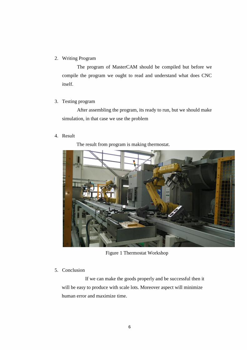
2. Writing Program
The program of MasterCAM should be compiled but before we
compile the program we ought to read and understand what does CNC
itself.
3. Testing program
After assembling the program, its ready to run, but we should make
simulation, in that case we use the problem
4. Result
The result from program is making thermostat.
Figure 1 Thermostat Workshop
5. Conclusion
If we can make the goods properly and be successful then it
will be easy to produce with scale lots. Moreover aspect will minimize
human error and maximize time.

7
3. RESULT ANALYZE
1. Determine The Step Size and The Machining Allowance
Determining allowance for machining parts up and down the steps of
the process are closely linked, including the processing speed of the process
and the next step size machining precision.
Table.1 Margin calculation and dimensional tolerances
Project name
Process Step Size Deviation margin
Margin
change
Finishing
ф32 - 0.04
- 0.25 0.3
+ 0.2
- 0.26
ф24 - 0.04
- 0.25 0.25
+ 0.21
- 0.21
ф18 - 0.032
- 0.212 0.25
+ 0.172
- 0.218
ф22 - 0.04
- 0.25 0.25
+ 0.21
- 0.21
Semi-
finishing
ф32.3 - 0.05
- 0.30 0.3
+ 0.25
- 0.25
ф24.25 - 0.04
- 0.25 0.25
+ 0.21
- 0.21
ф18.25 - 0.04
- 0.25 0.25
+ 0.21
- 0.21
ф22.25 - 0.04
- 0.25 0.25
+ 0.21
- 0.21
Roughing
ф32.6 - 0.05
- 0.30 1.8
+ 0.25
- 0.25
ф24.5 - 0.04
- 0.25 1.6
+ 0.21
- 0.21
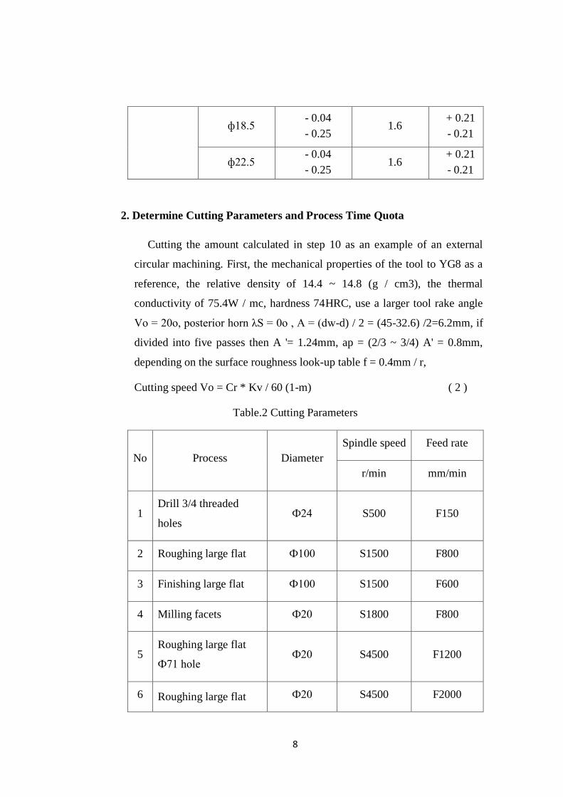
8
ф18.5 - 0.04
- 0.25 1.6
+ 0.21
- 0.21
ф22.5 - 0.04
- 0.25 1.6
+ 0.21
- 0.21
2. Determine Cutting Parameters and Process Time Quota
Cutting the amount calculated in step 10 as an example of an external
circular machining. First, the mechanical properties of the tool to YG8 as a
reference, the relative density of 14.4 ~ 14.8 (g / cm3), the thermal
conductivity of 75.4W / mc, hardness 74HRC, use a larger tool rake angle
Vo = 20o, posterior horn λS = 0o , A = (dw-d) / 2 = (45-32.6) /2=6.2mm, if
divided into five passes then A '= 1.24mm, ap = (2/3 ~ 3/4) A' = 0.8mm,
depending on the surface roughness look-up table f = 0.4mm / r,
Cutting speed Vo = Cr * Kv / 60 (1-m) ( 2 )
Table.2 Cutting Parameters
No Process Diameter
Spindle speed Feed rate
r/min mm/min
1 Drill 3/4 threaded
holes Ф24 S500 F150
2 Roughing large flat Ф100 S1500 F800
3 Finishing large flat Ф100 S1500 F600
4 Milling facets Ф20 S1800 F800
5 Roughing large flat
Ф71 hole Ф20 S4500 F1200
6 Roughing large flat Ф20 S4500 F2000

9
Ф61 hole
7 Finishing large flat
Ф61 hole Ф20 S4500 F2000
8 Roughing large flat Ф100 S1500 F800
9 Finishing large flat Ф100 S1500 F600
10 Drill the threaded
holesM12 * 1.5 Ф10 S3000 F150
11 M8 threaded hole
chamfering Ф14 S4000 F600
12 1/8 threaded hole
chamfering Ф14 S4500 F800
13 3/4 threaded hole
chamfering Ф14 S4000 F800
14 Milling 3/8 threaded
hole Ф14 S4000 F500
15 3/8 threaded hole
chamfering Ф14 S4000 F500
16 M12 * 1.5 screw hole
chamfering Ф14 S3500 F500
17 Ф9 center point hole Ф14 S4500 F500
18 Ф55 hole chamfering Ф14 S4500 F600
10
4. CONCLUSION
1. Conclusions
Based on the result of experiment that we have already done above,
we can conclude that the result of the applications which have been ran
by the code is same with the result of analytic CNC Machine.
Consequently this application is really precise enough to be applied
in the school for studying CNC, not only for studying purposes this
application could also be developed seriously in order to be applied in
industry.
2. Suggestions
The suggestions below were taken in order to more accurately the
result of research and as consideration for the next study. In order to
getting close result with real condition, the author gives some suggestion
below:
1. In the finding and Inputting the initial data should be careful based
on condition and experience. Condition is mean the ability of
common machine are different. Others, the environment factor are
giving big effect on the production parameters. And experience
means every special case need specials treatment as well.
2. Fabrication of cutting tools are so many around in the worlds. So,
need more attention in choosing cutting tool material and type for
rough-production. Even rough-machining is not finishing process but
give big influence in finishing product.
3. Others consideration is workpiece material are very much around in
the world. Before and during production may change the materials
properties also treatment during the process will be effected to
production parameters (like cooling system). so is need pay attention
when making simulation.

11
4. Finally, the authors hope that this report is useful for everyone who
read it and become recommendation and consideration for the next
production.

12
REFERENCES
[1] Avalone, E.A., Baumeister, Theodore, Marks’ Handbook for Mechanical
Engineering, 10th edition, McGraw-Hill, New York, 1996.
[2] Harrington, B.W., Development of Software Tools for Automation and
Acceleration of the Enginering Design Process, IEEE Aerospace
Applications Conference Proceedings, Vol. 4, pp. 265-275, 1998.
[3] Golenko, Andrzej.Fundamentals of Machine Design,Wroclaw University of
Technology, 2010
[4] Robert J Schilling. Fundamentals of Robotics-Analysis and Control [M]. New
Jersey: Prentice Hall, 1990: 25-27.
[6] Orlov P. Fundamentals of Machine Design. Moscow: Mir Pub, 1987: 65-69.
[7] Bicheng En. Modern CNC machine tools [M]. Beijing: Mechanical Industry
Press, 1991: 6-9.
[8] Hsu, Y.I.; Wang, S. S.: A new compensation method for geometry errors of
five- axis machine tools, International Journal of Machine Tools &
Manufacture, 47, 2007, 352–360.
[9] Liang, Z.; Jiangang, L.; Yunjiang, L.; Zexiang, L.: A Unified Framework of
Postprocessor for Multiaxis Machine Tools, International Conference on
Digital Manufacturing & Automation, 2010.
[10] My, C. A.: Integration of CAM Systems into Multi- Axes Computerized
Numerical Control Machines, 2010 Second International Conference on
Knowledge and Systems Engineering.
13
[11] Kollmann F. G. Rotating Elasto-Plastic Interference Fits. Trans. ASME, 80-
C2 / DET-11: 47-48.
[12] Patton W. J. Mechanical Power Transmission. New Jersey: Printice-Hall,
1980: 287.
[13] Kuehnle M R. Toroidal Drive Combines Concepts. Product Engineering.
Aug, 1979: 139-144.
[14] Mechanical Drive (Reference Issue). Machine Design. New Jersey: 52 (14),
1980: 27
Recommended