Luft/Wasser-WärmetauscherAir/water heat exchangersEchangeurs thermiques air/eauLucht/water-warmtewisselaarsLuft/vatten värmeväxlareScambiatori di calore aria/acquaIntercambiadores de calor aire/agua
SK 3363.XXXSK 3364.XXX
SK 3373.XXXSK 3374.XXXSK 3375.XXX
Montage-, Installations- und BedienungsanleitungAssembly and operating instructionsNotice d’emploi, d’installation et de montageMontage- en bedieningshandleidingMontage- och hanteringsanvisningIstruzioni di montaggio e funzionamentoInstrucciones de montaje y funcionamiento

EN
Contents1 Notes on documentation. . . . . . . . . . 31.1 Associated documents . . . . . . . . . . . . . . . . 31.2 CE labelling . . . . . . . . . . . . . . . . . . . . . . . . . 31.3 Retention of documents . . . . . . . . . . . . . . . 31.4 Symbols used. . . . . . . . . . . . . . . . . . . . . . . . 3
2 Safety notes . . . . . . . . . . . . . . . . . . . . 3
3 Device description . . . . . . . . . . . . . . . 43.1 Functional description . . . . . . . . . . . . . . . . 43.1.1 How it works. . . . . . . . . . . . . . . . . . . . . . . . . . 43.1.2 Control . . . . . . . . . . . . . . . . . . . . . . . . . . . . . . 43.1.3 Bus mode
(e-Comfort controller only) . . . . . . . . . . . . . . . 43.1.4 Safety equipment . . . . . . . . . . . . . . . . . . . . . . 53.1.5 Condensation. . . . . . . . . . . . . . . . . . . . . . . . . 53.1.6 Leak detection
(e-Comfort controller only) . . . . . . . . . . . . . . . 53.1.7 Door limit switch
(e-Comfort controller only) . . . . . . . . . . . . . . . 53.1.8 Additional interface X3
(e-Comfort controller only) . . . . . . . . . . . . . . . 53.2 Proper use . . . . . . . . . . . . . . . . . . . . . . . . . . 53.3 Scope of supply . . . . . . . . . . . . . . . . . . . . . . 5
4 Assembly and connection . . . . . . . . 64.1 Choosing the installation site . . . . . . . . . . . 64.2 Assembly instructions . . . . . . . . . . . . . . . . 64.2.1 General . . . . . . . . . . . . . . . . . . . . . . . . . . . . . 64.2.2 Layout of the components in the enclosure. . 64.3 Assembling the air/water
heat exchanger. . . . . . . . . . . . . . . . . . . . . . . 74.3.1 Preparing the mounting cut-out . . . . . . . . . . . 74.3.2 Assembling the air/water heat exchanger . . . 74.4 Connecting the condensate discharge . . . 94.5 Connecting the water connection . . . . . . . 94.5.1 Notes on water quality . . . . . . . . . . . . . . . . . 104.5.2 Preparation and maintenance of the water
in recooling systems . . . . . . . . . . . . . . . . . . 104.6 Notes on electrical installation . . . . . . . . . 114.6.1 Connection data . . . . . . . . . . . . . . . . . . . . . 114.6.2 Overvoltage protection
and supply line load . . . . . . . . . . . . . . . . . . 114.6.3 Door limit switch
(e-Comfort controller only) . . . . . . . . . . . . . . 114.6.4 Potential equalisation. . . . . . . . . . . . . . . . . . 114.6.5 Installing the power supply . . . . . . . . . . . . . 11
5 Commissioning . . . . . . . . . . . . . . . . 13
6 Operation . . . . . . . . . . . . . . . . . . . . . 136.1 Control using the Basic controller . . . . . 136.1.1 Display and system analysis. . . . . . . . . . . . 136.1.2 Properties . . . . . . . . . . . . . . . . . . . . . . . . . . 136.1.3 General programming information . . . . . . . 136.1.4 Operation of the Basic controller . . . . . . . . 136.1.5 Setting the temperature. . . . . . . . . . . . . . . . 146.1.6 Setting of system messages . . . . . . . . . . . . 146.1.7 Programming and control
of the Basic controller . . . . . . . . . . . . . . . . . 146.1.8 Reset of r6 and r7
(min./max. internal temperature) . . . . . . . . . 146.1.9 System message contact (K1; floating) . . . 156.1.10 Programming overview of Basic controller . 156.2 Control using the e-Comfort controller. . 166.2.1 Properties . . . . . . . . . . . . . . . . . . . . . . . . . . 166.2.2 Launching test mode . . . . . . . . . . . . . . . . . 166.2.3 General programming information . . . . . . . 166.2.4 Eco-mode . . . . . . . . . . . . . . . . . . . . . . . . . . 176.2.5 Editable parameters . . . . . . . . . . . . . . . . . . 186.2.6 Bus connection
(only when interconnecting several units with an e-Comfort controller). . . . . . . . . . . . 19
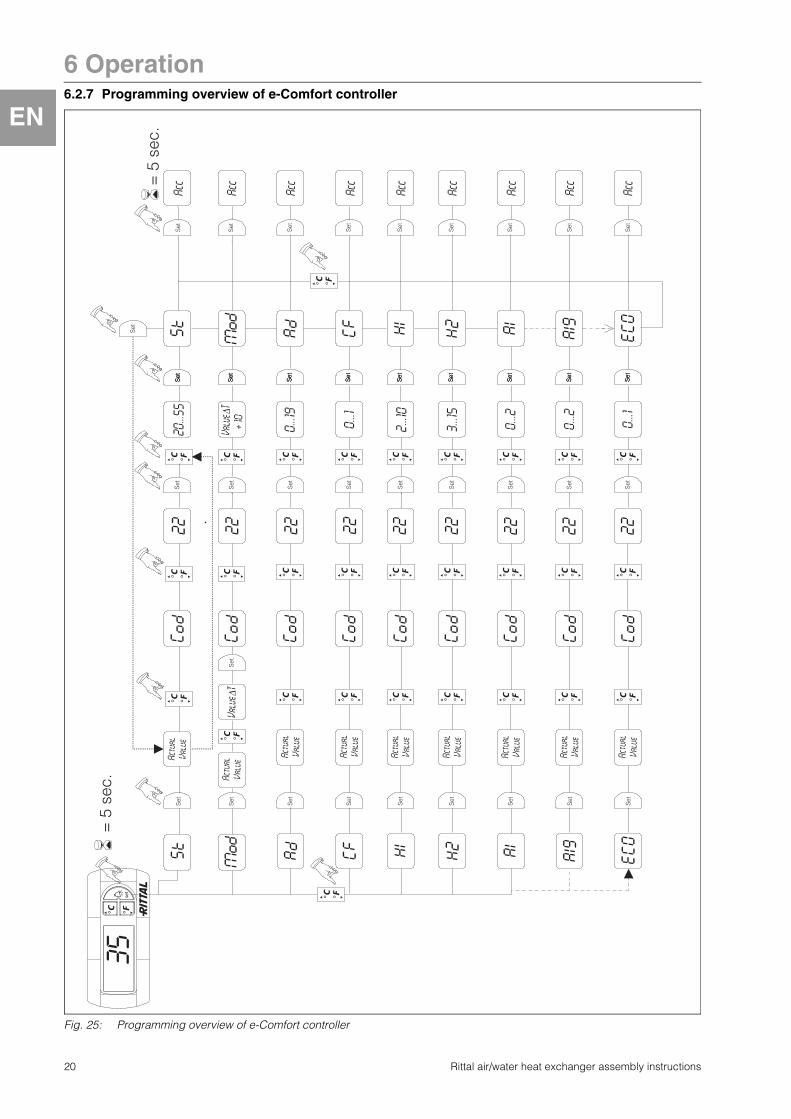
6.2.7 Programming overview of e-Comfort controller . . . . . . . . . . . . . . . . 20
6.2.8 Defining system messages for evaluation . 216.2.9 Setting the master-slave identifier. . . . . . . . 216.2.10 Evaluating system messages . . . . . . . . . . . 22
7 Inspection and maintenance. . . . . . 237.1 General . . . . . . . . . . . . . . . . . . . . . . . . . . . . 23
8 Emptying, storage and disposal. . . 23
9 Technical specifications . . . . . . . . . 24
10 List of spare parts . . . . . . . . . . . . . . 27
11 Further technical information . . . . . 2811.1 Hydrological data . . . . . . . . . . . . . . . . . . . 2811.2 Characteristic curves . . . . . . . . . . . . . . . . 2911.2.1 Water resistance . . . . . . . . . . . . . . . . . . . . . 29
12 Appendix 1: Cut-out and hole sizes . . . . . . . . . . . 3012.1 Dimensions for external
and internal mounting. . . . . . . . . . . . . . . . 30
13 Appendix 2: Application example Parallel connection of 4 air/water heat exchangers . . . . . . 33
2 Rittal air/water heat exchanger assembly instructions

1 Notes on documentation
EN
1 Notes on documentationThese assembly instructions are aimed at tradesper-sons who are familiar with assembly and installation of the air/water heat exchanger, and are trained specialists who are familiar with the operation of the air/water heat exchanger.1.1 Associated documentsThere is one set of instructions for the unit types described here:– Assembly, installation and operating instructions
enclosed with the unit as a printed document and/or on CD-ROM.
We cannot accept any liability for damage asso-ciated with failure to observe these instructions. Where applicable, the instructions for any acces-sories used also apply.
1.2 CE labellingThe declaration of conformity is supplied with the unit as a separate document.
1.3 Retention of documentsThese instructions and all associated documents constitute an integral part of the product. They must be given to the plant operator. The plant operator is responsible for storage of the documents so they are readily available when needed.
1.4 Symbols usedPlease observe the following safety instructions and other notes in this guide:Symbol identifying required actions:� The bullet point indicates an action to be per-
formed.
Safety and other notes:
2 Safety notesPlease observe the following general safety notes when assembling and operating the unit:– Assembly, installation and servicing may only be
performed by properly trained specialists.– The minimum water inlet temperature of +1 °C
must not be reduced at any point in the water cycle. Otherwise there is danger of frost damage!
– Use antifreeze agents only with the manufacturer’s consent.
– Do not obstruct the air inlet and air outlet of the air/water heat exchanger inside the enclosure (see also section 4.2.2).
– The heat loss of the components installed in the enclosure must not exceed the specific useful cooling output of the air/water heat exchanger.
– Use only original spare parts and accessories.– Do not make any changes to the air/water heat
exchanger other than those described in these instructions or associated instructions.
– The mains connector of the air/water heat exchanger must only be connected and disconnected with the system de-energised. Connect the pre-fuse specified on the rating plate.
– Always disconnect the unit from the supply voltage before servicing or maintenance work.
– Readily flammable objects/materials must not be stored in the immediate vicinity of the air/water heat exchanger.
Danger!Immediate danger to life and limb!
Caution!Potential threat to the product and its environment.
Note:Useful information and special features.
Rittal air/water heat exchanger assembly instructions 3
3 Device description
EN
3 Device descriptionDepending on the model chosen, your air/water heat exchanger may vary in appearance from the illustrations contained in these instructions. However, the functions are identical in principle.Fig. 1: Device description
Key1 Cover2 Display (controller)3 X1 terminal strip (unit rear)4 X2 master/slave connection (e-Comfort controller)5 X3 optional serial interface (unit rear)6 Potential equalisation7 Rating plate8 Cooling water inflow (underside of the unit)9 Condensate discharge (underside of the unit)10 Cooling water return (underside of the unit)11 Dispatch bag
3.1 Functional descriptionAir/water heat exchangers are designed and built to dissipate heat from enclosures by cooling the air in-side the enclosure and so protect the temperature-sensitive components. Air/water heat exchangers are particularly appropriate for the temperature range of up to +70 °C where comparable units, such as air/air heat exchangers, enclosure cooling units or fan-and-filter units, cannot be used for system rea-sons to effectively and economically dissipate heat loss. The air/water heat exchanger may be externally and internally mounted on all enclosure outer walls.
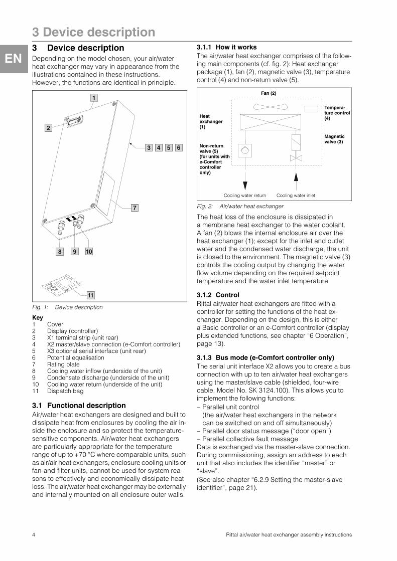
3.1.1 How it worksThe air/water heat exchanger comprises of the follow-ing main components (cf. fig. 2): Heat exchanger package (1), fan (2), magnetic valve (3), temperature control (4) and non-return valve (5).
Fig. 2: Air/water heat exchanger
The heat loss of the enclosure is dissipated in a membrane heat exchanger to the water coolant. A fan (2) blows the internal enclosure air over the heat exchanger (1); except for the inlet and outlet water and the condensed water discharge, the unit is closed to the environment. The magnetic valve (3) controls the cooling output by changing the water flow volume depending on the required setpoint temperature and the water inlet temperature.
3.1.2 ControlRittal air/water heat exchangers are fitted with a controller for setting the functions of the heat ex-changer. Depending on the design, this is either a Basic controller or an e-Comfort controller (display plus extended functions, see chapter “6 Operation”, page 13).
3.1.3 Bus mode (e-Comfort controller only)The serial unit interface X2 allows you to create a bus connection with up to ten air/water heat exchangers using the master/slave cable (shielded, four-wire cable, Model No. SK 3124.100). This allows you to implement the following functions:– Parallel unit control
(the air/water heat exchangers in the network can be switched on and off simultaneously)
– Parallel door status message (“door open”) – Parallel collective fault message Data is exchanged via the master-slave connection. During commissioning, assign an address to each unit that also includes the identifier “master” or “slave”.(See also chapter “6.2.9 Setting the master-slave identifier”, page 21).
8
7
1
9 10
3 4 54 5 6
11
2
Cooling water return
Magnetic valve (3)
Tempera-ture control (4)
Cooling water inlet
Non-return valve (5) (for units with e-Comfort controller only)
Fan (2)
Heat exchanger (1)
4 Rittal air/water heat exchanger assembly instructions

3 Device description
EN
Rittal air/water heat exchanger assembly instructions 5
3.1.4 Safety equipment– To protect against overcurrent, the fan is equipped
with a thermal winding protection.– The device has floating contacts on the connection
terminal (terminals 3 – 5), which may be used to retrieve system messages from the device, e.g. via PLC (1 x change-over contact Basic controller, 2 x normally open contacts e-Comfort controller).
– Air/water heat exchangers with e-Comfort control-ler possess a leakage sensor and a condensate warning.
3.1.5 CondensationAt high levels of humidity and low cooling water tem-peratures inside the enclosure, condensation may form on the heat exchanger.Any condensation that forms on the heat exchanger (with high humidity and low water temperatures) is routed to the bottom and out of the unit via a drain opening in the heat exchanger tray. For this purpose, a hose must be connected to the condensate nozzle (see “4.4 Connecting the condensate discharge”, page 9). The condensate must be able to run off freely. The hose used for draining off condensate must be laid free from kinks and checked for correct drainage.Air/water heat exchangers with e-Comfort controller possess a leakage sensor and a condensate warning.Condensate hoses are available as accessories (refer also to Accessories in the Rittal Catalogue).
3.1.6 Leak detection (e-Comfort controller only)
If a leakage or pipe breakage occurs in the water circuit of the air/water heat exchanger, a magnetic valve immediately stops the cooling water supply, the floating change-over contact is activated and the fan switched off.
3.1.7 Door limit switch (e-Comfort controller only)
The air/water heat exchanger may be operated with a door limit switch connected. The door limit switch is not included with the supply (available as an accessory, Model No. SZ 4127.010).The door limit switch function causes the fan and the magnetic valve in the air/water heat exchanger to be switched off after approximately 15 seconds when the enclosure door is opened (contacts 1 and 2 closed). This prevents the formation of condensation inside the enclosure while the enclosure door is open.The fan will start up after about 15 seconds on closure of the door. The connection is made at ter-minals 1 and 2. The extra-low voltage is supplied by the internal power pack; the current is approx. 30 mA DC.
3.1.8 Additional interface X3 (e-Comfort controller only)
An additional interface card may be connected to the 9-pole SUB-D connector X3 in order to incorpo-rate the air/water heat exchanger into higher-level monitoring systems (available as an accessory, interface card Model No. SK 3124.200).
3.2 Proper useRittal air/water heat exchangers were developed and designed in accordance with the state of the art and the recognised rules governing technical safety. Nevertheless, if used improperly, they may pose a threat to life and limb or cause damage to property. The unit is only intended for cooling enclosures. Any other use is deemed improper. The manufac-turer will not be liable for any damages caused as a result of improper use, or for incorrect assembly, installation or use. All risk is borne solely by the user. Proper usage also includes the observation of all valid documents and compliance with the inspection and servicing conditions.
3.3 Scope of supplyThe unit is supplied in a packaging unit in a fully assembled state. Please check the scope of supply for completeness.
Tab. 1: Scope of supply
Note:The door limit switches must only be connected free from potential. No external voltages!
Note:The electrical signals at the interface are of an extra-low voltage (not extra-low safety voltages to EN 60 335).
Quantity Description
1 Air/water heat exchanger
11144
1
11
Dispatch bag:– Sealing tape– Plug-in terminal strip– Spacer bolts including assembly parts– Sealing bungs (not with unit types
SK 3363.XXX/SK 3364.XXX)– Assembly, installation and
operating instructions– Declaration of conformity– Safety notes
1 Drilling template

4 Assembly and connection
EN
6 Rittal air/water heat exchanger assembly instructions
4 Assembly and connection
4.1 Choosing the installation siteWhen choosing the installation site for the enclosure, please observe the following:– The air/water heat exchanger must be installed
and operated in a vertical position (maximum deviation: 2°).
– The ambient temperature must not exceed +70 °C.– It must be possible to fit a condensate discharge
(see “4.4 Connecting the condensate discharge”, page 9).
– It must be possible to fit a cooling water supply and return (see “4.5 Connecting the water connection”, page 9).
– The mains connection data as stated on the rating plate of the unit must be guaranteed.
– For ease of servicing, appropriate access to the device must be guaranteed.
4.2 Assembly instructions
4.2.1 General– Check the packaging carefully for signs of damage.
Any packaging damage may be the cause of a subsequent functional failure.
– The enclosure must be sealed on all sides (IP 54). Increased condensation will occur if the enclosure is not airtight.
– The air inlet and outlet must not be obstructed on the inside of the enclosure.
4.2.2 Layout of the components in the enclosure
Fig. 3: Never direct the cold airflow at active components
Exercise particular caution with the airflow from the blowers of built-in electronic components (see fig. 3).
Fig. 4: Targeted air routing inside the enclosure
Caution! Risk of condensation! When arranging the components inside the enclosure, please ensure that the cold airflow from the air/water heat exchanger is not directed at active components. Please also ensure that the cold airflow is not directed at the warm exhaust airflow from active components such as inverters. This may lead to an air short-circuit and therefore prevent adequate climate con-trol, or may even cause the air/water heat exchanger’s internal safety devices to cease cooling operation.
Note:The air/water heat exchangers should never be fitted directly behind the mounting plate. If it is not possible to install the unit any other way, appropriate air baffle plates should be used, and air inlet and outlet openings should be provided in the mount-ing plate.It is important to ensure even air circulation inside the enclosure. Under no circum-stances should air inlet and outlet openings be obstructed, otherwise the cooling per-formance of the unit will be reduced. Ensure a suitable distance from electronic com-ponents and other installed enclosures so that the required air circulation is not obstructed and prevented.
200

4 Assembly and connection
EN
4.3 Assembling theair/water heat exchangerThe air/water heat exchanger can be mounted on the outer walls or the door of the enclosure.For this purpose, the appropriate enclosure panel or door must be cut out using the supplied drilling template.
4.3.1 Preparing the mounting cut-out� Stick the supplied drilling template onto the side
panel or door of the enclosure using adhesive tape. The heat exchanger is suitable for both exter-nal and internal mounting.
There are dimensioning lines on the drilling template to suit the installation type for your air/water heat exchanger.
� Make the cut-outs including the line width as per the drilling template. Deburr the cut-outs.
4.3.2 Assembling the air/water heat exchanger
External mounting
Step 1:� Stick sealing tape to all four edges at the rear of
the device.
Fig. 5: Stick sealing tape to all four edges
Step 2:� Insert the 4 spacers (external thread) into the
mounting surface through the holes, and secure from the inside of the enclosure using the relevant washers and nuts.
Fig. 6: Insert the spacers through the holes and secure
Step 3:� Push the device over the spacers and secure with
the relevant rubber washers, washers and screws (observe the correct assembly sequence).
Fig. 7: Push the device over the spacers and screw-fasten
Risk of injury!Carefully deburr all cut-outs to prevent injuries caused by sharp edges.
Note:In order to achieve a permanent seal between the air/water heat exchanger and the enclosure, the mounting surface should be reinforced or supported if necessary.
Note:For both types of mounting (internal and external), use the assembly parts supplied in the pack.
Note:For models SK 3373.XXX, 3374.XXX and 3375.XXX, steps 4 and 5 are additionally required.
1.
4x2.
1
Rubber1
3.
Rittal air/water heat exchanger assembly instructions 7

4 Assembly and connection
EN
8 Rittal air/water heat exchanger assembly instructions
Step 4:� Twist the side locking screws in the enclosure
cover in a clockwise direction as far as they will go, until the sealing tape adheres securely.
Fig. 8: Twist the screws in a clockwise direction as far as they will go
Step 5:� Using the stoppers, seal the 4 openings in the
cover.
Fig. 9: Seal the openings in the cover
Full internal mounting
Step 1:� Stick sealing tape to all four edges at the front of
the device.
Fig. 10: Stick sealing tape to all four edges
Step 2:� Hold the 4 spacers (internal thread) in place on
the inside of the enclosure, and secure from the outside using the relevant washers and screws.
Fig. 11: Secure the spacers
Step 3:� Push the device over the spacers and secure with
the relevant washers and nuts.
Fig. 12: Push the device over the spacers and screw-fasten
Step 4:� Using the stoppers, seal the 4 openings in the
cover.
Fig. 13: Seal the openings in the cover
TX30
4x
4.
4x
5.
Note:For models SK 3373.XXX, 3374.XXX and 3375.XXX, step 4 is additionally required.
Note:The enclosure must be sealed on all sides, especially in the vicinity of the cable entry openings and the enclosure base.
1.
4x2.
3.
4x
4.

4 Assembly and connection
EN
4.4 Connecting the condensate dischargeA flexible condensate discharge hose Ø 12 mm (1/2˝) can be fitted to the air/water heat exchanger (see fig. 14).The condensate discharge– must be laid with a suitable and constant gradient(no siphoning).– must be laid without kinks.– must not have a reduced cross-section if extended.The condensate hose is available as an accessory (refer also to Accessories in the Rittal Catalogue).
Fig. 14: Connecting the condensate discharge
KeyCooling water connection (inlet)Cooling water connection (return)Condensate discharge
� Connect a suitable hose to the condensate nozzle (at the bottom of the unit) and secure it with a hose clip (with 2 Nm torque).
� Lay the condensate hose, e.g. into a drain.� To prevent the water from backing up, the hose
cross-section must not be restricted!
4.5 Connecting the water connectionThere are 4 different options for connecting water to the air/water heat exchanger.
a) 1/2˝ connector sleeve (included with the supply)In its delivered state, a compression-proof, flexible cooling water hose Ø 12 mm (1/2˝) may be connected to the air/water heat exchanger for both the inlet and the return.The cooling water hose– must be laid without kinks– must not have a reduced cross-section if extended
and, if necessary, must be insulated.
Fig. 15: Connecting the cooling water inlet and return
KeyCooling water connection (inlet)Cooling water connection (return)Condensate discharge
b) Fixed pipework with G 3/8˝ external thread (included with the supply)
In its delivered state, fixed pipework with a G 3/8˝ external thread may be connected to the air/water heat exchanger for both the inlet and the return. � To this end, you will need to remove the connector
sleeve attached to the device (see fig. 16).� The fixed pipework should be tightened with
25 Nm.
Fig. 16: Remove the connector sleeve
21
3
1
2
3
Note:When loosening the connector sleeve, it is vital to ensure that the fitting on the device end is fixed with an SW22 open-jawed spanner. The connection inside the device could develop a leak.
3
21
1
2
3
25 Nm
Rittal air/water heat exchanger assembly instructions 9

4 Assembly and connection
EN
c) Fixed pipework with G 3/8˝ internal thread(Model No. SK 3201.900)The G 3/8˝ internal thread adaptor, available as an accessory, allows you to connect fixed pipework to the air/water heat exchanger for both the inlet and the return. � To this end, you will need to remove the connector
sleeve attached to the device (see page 9, fig. 16).
d) Fixed pipework with 1/2˝ NPT (Model No. SK 3201.930)
The 1/2˝ NPT adaptor, available as an accessory, allows you to connect fixed pipework to the air/water heat exchanger for both the inlet and the return. � To this end, you will need to remove the connector
sleeve attached to the device (see page 9, fig. 16).
4.5.1 Notes on water qualityTo ensure the reliable operation of the above-mentioned units, the VBG guidelines for cooling water must be observed (VGB-R 455 P).The cooling water must not contain any limescale deposits; in other words, it should have a low level of hardness, in particular, a low level of calcium hard-ness. For recooling within the plant, the calcium hardness should not be too high. On the other hand, the water should not be so soft that it attacks the materials. When recooling the cooling water, the salt content should not be allowed to increase exces-sively due to the evaporation of large quantities of water, since electrical conductivity increases as the concentration of dissolved substances rises, and the water thereby becomes more corrosive.� Always add the appropriate volume of fresh water.� Always remove part of the enriched water.
The following criteria for the cooling water must be observed: – Water with high gypsum content is unsuitable for
cooling purposes because it has a tendency to form boiler scale that is particularly difficult to remove.
– The cooling water should be free from iron and manganese, because otherwise deposits may occur that accumulate in the pipes and block them.
– At best, organic substances should only be present in small quantities, because otherwise sludge deposits and microbiological contamina-tion may occur.
4.5.2 Preparation and maintenance of the water in recooling systems
Depending on the type of installation to be cooled, certain requirements are placed on the cooling water with respect to purity. According to the level of con-tamination and the size and design of the recooling systems, a suitable process is used to prepare and/or maintain the water.The most common types of contamination and most frequently used techniques to eliminate them in industrial cooling are:
Tab. 2: Water contaminants
Note:The water circuit should be protected from ingress of dirt or excess pressure (maximum permitted operating pressure 10 bar)!
Note:Observe the flow direction and check for leaks!
Note:The units do not have any separate ventilation.For pressure-sealed systems, install the appropriate ventilation equipment on the water side.
Contamination of the water
Procedure
Mechanical contamination
Filter the water using:– Mesh filter– Gravel filter– Cartridge filter– Precoated filter
Excessive hardness Water softening via ion exchange
Moderate content of mechanical contaminants and hardeners
Addition of stabilisers and/or dispersing agents to the water
Moderate content of chemical contaminants
Addition of passifiers and/or inhibitors to the water
Biological contaminants, slime bacteria and algae
Addition of biocides to the water
10 Rittal air/water heat exchanger assembly instructions

4 Assembly and connection
EN
Rittal air/water heat exchanger assembly instructions 11
4.6 Notes on electrical installationWhen performing the electrical installation, it is impor-tant to observe all valid national and regional regula-tions as well as the provisions of the responsible power supply company. Electrical installation must only be carried out by a qualified electrician who is responsible for compliance with the existing standards and regulations.
4.6.1 Connection data– The connected voltage and frequency must cor-
respond to the values stated on the rating plate.– The air/water heat exchanger must be connected
to the mains via an all-pin isolating device which ensures at least 3 mm contact opening when switched off.
– No additional temperature control may be con-nected upstream of the unit at the supply end.
– Install the pre-fuse cited on the rating plate (miniature circuit-breaker or gG/(gL) fuse) to protect the cable and equipment from short-circuits.
– The mains connection must ensure low-noise potential equalisation.
4.6.2 Overvoltage protection and supply line load
– The unit does not have its own overvoltage protec-tion. Measures must be taken by the operator at the supply end to ensure effective lightning and overvoltage protection. The mains voltage must not exceed a tolerance of ±10%.
– The fans in single-phase units are intrinsically safe (thermal winding protection). The same also applies to all transformer versions and to special-voltage units which are likewise equipped with a transformer.
4.6.3 Door limit switch (e-Comfort controller only)
– Each door limit switch must only be assigned to one air/water heat exchanger.
– Several door limit switches may be connected in parallel and operated on one air/water heat exchanger.
– The minimum cross-section of the connection cable is 0.3 mm2 for a cable length of 2 m. We recommend the use of a shielded cable.
– The line resistance to the door limit switch must not exceed a maximum of 50 Ω.
– The door limit switch only supports a floating connection; no external voltages.
– The contact of the door limit switch must be closed when the door is open.
The safety extra-low voltage for the door limit switch is provided by the internal power pack: current approx. 30 mA DC.� Connect the door limit switch to terminals 1 and
2 of the connector.� The door limit switch is available as an accessory
(Model No. SZ 4147.010).
4.6.4 Potential equalisationRittal recommends connecting a conductor with a nominal cross-section of at least 6 mm2 to the potential equalisation connection point on the air/water heat exchanger and incorporating it into the existing potential equalisation system.According to the standard, the PE conductor in the mains connection cable is not classified as an equipotential bonding conductor.
4.6.5 Installing the power supply� Complete the electrical installation in accordance
with the wiring plan to be found on the rear of the air/water heat exchanger.
� For devices SK 3363.XXX and SK 3364.XXX in special voltage variants, an external transformer is required (see also Rittal system accessories).
� To be able to evaluate the system messages of the air/water heat exchanger via the system message relay, a corresponding low-voltage cable must be connected additionally on terminals 3 – 5.

4 Assembly and connection
EN
Fig. 17: Electrical wiring plan no. 1
KeyA1 Power PCBA2 Display terminalB1 Temperature sensor, internal temperatureC2 Operating capacitorsKx Collective fault relay M2 FanS2 Float-actuated switch (optional)X1 Main terminal strip (terminals 1 and 2 are free)Y1 Magnetic valveT1 Transformer (optional)
Tab. 3: Contact data
Fig. 18: Electrical wiring plan no. 2
KeyA1 Power PCBA2 Temperature sensor
(Basic or e-Comfort controller)B1 Temperature sensor, internal temperatureKx Relay K1 collective fault 1
Relay K2 collective fault 2M2 FanC2 Operating capacitorS1 Door limit switch
(without door limit switch: terminal 1, 2 open)S2 Float-actuated switch (closed without water)X1 Main terminal stripX2 Master-slave connectionX3 Serial interface (optional)T1 Transformer (optional)Y1 Magnetic valve
Note:For technical data, refer to the rating plate.
ACcos f = 1
DCL/R = 20 ms
I max. = 2 AU max. = 250 V
I min. = 100 mAU max. = 200 VU min. = 18 VI max. = 4 A
2NTC_I
2NTC_E
PE
PE
Power/G1
L N KxPE 1 2 3 3 2 1
D0-E D0-I/Y1 /M2
1 3 42
A2
A1
Mains
L1 N PE 21 3 4 5X1
M2Y11~M
C2
D0-E/Kx
8 pol.TO INTERFACE
8
S2
B1
Option T1
L1L2N
T1
L1 L1/N
L1 L2/N
SK 3363.1XX, SK 3364.1XX,SK 3373.1XX, SK 3374.1XX, SK 3375.1XX
83
PETerm
Level
NTC_ENTC_I
NTC_ANTC_C
F2
Power/G1 Kx
PE
L S1 K2 K1
1 2 3
1 2 3 1 2 123
21 23 31
N
M1 M2 M412
S
S2
1~
M2
AC
A1
A2X2
MS1 Serial
X3
Mains S1
L1 PE 21 3 4
2221
5L2NX1
Y1
PE PE
PE
PE PE
Option T1
L1L2N
T1
L1 L1/N
L1 L2/N
4
2B1
C2
SK 3363.5XX, SK 3364.5XX,SK 3373.5XX, SK 3374.5XX, SK 3375.5XX
12 Rittal air/water heat exchanger assembly instructions

5 Commissioning
EN
Rittal air/water heat exchanger assembly instructions 13
5 Commissioning� Once all the assembly and installation work is
complete, switch on the power supply to the air/water heat exchanger.
The air/water heat exchanger starts running:– with Basic controller: The enclosure internal
temperature is displayed.– with e-Comfort controller: The software version
of the controller first appears for approx. 2 sec., then the enclosure internal temperature appears in the 7-segment display.
You can now make your individual settings on the unit, e.g. set the temperature or (with e-Comfort controller only) assign the network identifier, etc. (refer to the “Operation” chapter).
6 Operation You can operate the air/water heat exchanger using the controller on the front of the unit (fig. 1, no. 2, page 4).
6.1 Control using the Basic controllerFor unit types SK 3363.1XX to 3375.1XX.
6.1.1 Display and system analysis
Fig. 19: Display and system analysis of the Basic controller
6.1.2 PropertiesThe air/water heat exchanger operates automati-cally, i.e. after switching on the power supply, the fan (see fig. 2, page 4) will run continuously and permanently circulate the internal enclosure air. The magnetic valve controls the cooling water flow as specified by the temperature setpoint.
The built-in Basic controller ensures automatic normal shut-down operation of the air/water heat exchanger by the value of the fixed preset switching difference of 5 K.
6.1.3 General programming information Using buttons H2, H3 and H4 (fig. 19) you can change 3 parameters within the preset ranges (min. value, max. value). Tables 5 and 6 on page 14 show the parameters which can be altered.
6.1.4 Operation of the Basic controllerThe display terminal “H1” consists of a 3-position 7-segment display which indicates the temperature in °C as well as any system messages. The current enclosure internal temperature is usually displayed permanently. In the event of a system message, this will alternate with the internal temperature display.
6.1.5 Setting the temperature The setting of the enclosure internal temperature is preset at the factory to 35 °C. To change the value press key H2 (▲ K1) or H3 (▼ K2) for one second until °1 appears in the display, then confirm with the H4 “set” key.The set value can then be altered within the preset parameters (+20 °C to +55 °C) via the keys H2 (▲ K1) or H3 (▼ K2). Press the H4 “set” key for 5 seconds to save the new value. The current enclo-sure internal temperature is displayed again.
Tab. 4: Warning messages on the display
Note on limiting the volumetric flowFrom a volumetric flow of > 400 l/h, no significant increase in cooling output is achieved. Appropriate measures must be taken to regulate the flow rate, e.g. balanc-ing valves (Model No. SK 3301.930/.940).
H2 = Key K1 H4 = Key set/°F
H1 = Display terminal H3 = Key K2
Note:With the Basic controller, the temperature is preset at the factory to +35 °C. In order to save energy, do not set the temperature lower than that actually necessary.
Alarm no.
System message
Cause Remedy
HI Internal temperature of enclosure too high
Cooling capacity inadequate/unit undersized/unit defective
Check cooling capacity/check unit
LO Internal temperature of enclosure too low
Ambient tempera-ture too low/no heat loss in the enclosure
Check unit

6 Operation
EN
6.1.6 Setting of system messages To change the system messages keep the H4 “set” key pressed for 5 seconds. The controller is now in programming mode. While in programming mode, if you do not press any buttons for approx. 60 sec., the display will first flash, then the controller will switch back to normal display mode.You can then navigate in the levels with the H2 (▲ K1) or H3 (▼ K2) keys (see tab. 4). The level is selected by pressing the H4 button. The parameters are changed with the H2 (▲ K1) or H3 (▼ K2) keys. Press the H4 “set” key for 5 seconds to confirm the new value.
6.1.7 Programming and control of the Basic controller
See also fig. 25 on page 20.
Tab. 5: Setting the setpoint
Tab. 6: Setting the system messages, monitoring of the min./max. enclosure internal temperature
Progr. level
Display screen
Parameters Min. value
Max. value
Factory setting
Description
1 °1 Internal enclosure temperature setpoint Ti
20 55 35 The setting of the enclosure internal temperature is preset at the factory to 35 °C and may be altered within a range of +20 °C to +55 °C. When the setpoint is reached, the H2 (▲ K1) key is lit continuously.
Progr. level
Display screen
Parameters Min. value
Max. value
Factory setting
Description
0 Ps – – – – No function
2 H5 Software version number
– – – Displays the current version number of the device software.
3 AH Alarm – maximum temperature
AL +150 50 Maximum temperature alarm (NOT in relation to the nominal value). HI is displayed alternating with the internal temperature. The “HI” alarm is displayed when the internal temperature > HI.The alarm stops when the internal temperature < AH –2K.
4 AL Alarm – minimum temperature
–50 AH 20 Minimum temperature alarm (NOT in relation to the nominal value). LO is displayed alternating with the internal temperature. The “LO” alarm is displayed when the internal temperature < LO.The alarm stops when the internal temperature > AL +2K.
5 r8 Reset of r6 and r7 0 1 0 Reset of r6 and r7. Set this parameter to 1 to reset the stored maximum and minimum values of r6 and r7 to the respective current actual value.
6 r7 Querying of the min. internal temperature
–50 +150 0 Stores the min. internal enclosure temperature occurring after > 1 min.
7 r6 Querying of the max. external temperature
–50 +150 0 Stores the max. ambient temperature occurring after > 1 min.
6.1.8 Reset r6 and r7 (min./max. internal temperature)
To reset the stored internal temperatures keep the H4 “set” key pressed for 5 seconds. Navigate to level r8 with the H2 (▲ K1) or H3 (▼ K2) keys. Press the
H4 “set” key and change the parameter from 0 to 1 using the H2 (▲ K1) or the H3 (▼ K2) keys. Press the H4 “set” key for 5 seconds to confirm resetting the values.
14 Rittal air/water heat exchanger assembly instructions
6 Operation
EN
6.1.9 System message contact (K1; floating)The relay is normally closed. All assigned system messages lead to the relay dropping out – and likewise to loss of the control voltage. Terminal strip X1 provides the connection. For contact data and occupancy – see the wiring diagram in chapter “4.6.5 Installing the power supply”, page 11.K1 fault signal relay (normally open contact/change-over contact) – Terminal 3: NC (normally closed)– Terminal 4: C (connection of the supply voltage to
the fault signal relay)– Terminal 5: NO (normally open)The NC and NO definitions refer to the de-energised state.
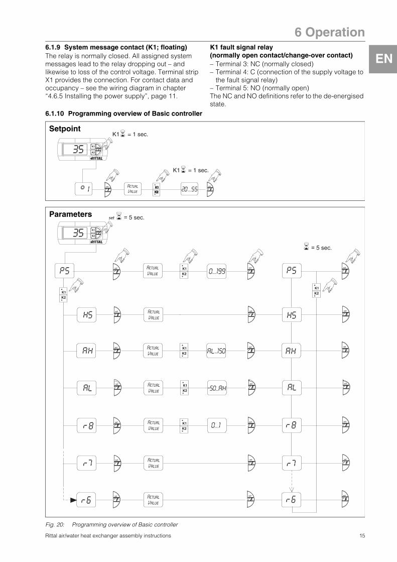
6.1.10 Programming overview of Basic controller
Rittal air/water heat exchanger assembly instructions 15
Fig. 20: Programming overview of Basic controller
K1
K2
K1
K2
K1 = 1 sec.
K1 = 1 sec.
Setpoint
K1
K2
K1
K2
K1
K2K1
K2
K1
K2
K1
K2
= 5 sec.
= 5 sec.
K1
K2
K1
K2
Parameters

6 Operation
EN
6.2 Control using the e-Comfort controllerFor unit types SK 3363.5XX to SK 3375.5XX.Fig. 21: Display and system analysis of the e-Comfort controller
Key1 Programming button, also display of the set
temperature unit (degrees Celsius)2 Set button3 Programming button, also display of the set
temperature unit (degrees Fahrenheit)4 7-segment display
6.2.1 Properties – Door limit switch function– Monitoring of all motors (fans)– Master-slave function with a maximum of ten units.
One device functions as a master unit. Once the set temperature is reached by one of the con-nected slave units or in the event of the door limit switch function, the affected slave unit will report to the master unit, which will switch all the other air/water heat exchangers on or off as required.
– Switching hysteresis: adjustable from 2 – 10 K, preset to 5 K.
– Visualisation of the current enclosure internal temperature and all error messages in the 7-seg-ment display.
The air/water heat exchanger operates automati-cally, i.e. after switching on the power supply, the fan (see page 4, fig. 2) will run continuously and permanently circulate the internal enclosure air. The fan and the magnetic valve are controlled by the e-Comfort controller. The e-Comfort controller has a 7-segment display (fig. 21, no. 4). After switching on the power supply, the current software version initially appears on this display for approx. 2 seconds. In regular operation, the display shows both the temperature (in degrees Celsius or Fahrenheit – users may switch between the two) and any error messages.
The current enclosure internal temperature is usually displayed permanently. In the event of an error mes-sage, this alternates with the temperature display.The unit is programmed using buttons 1 – 3 (fig. 21). The relevant parameters also appear in the display.
6.2.2 Launching test modeThe e-Comfort controller is equipped with a test function, whereby the air/water heat exchanger commences cooling operation independently of the set temperature or door limit switch function.� Simultaneously press buttons 1 and 2 (fig. 21)
for at least 5 seconds.The air/water heat exchanger starts running.After approximately 5 minutes or upon reaching 15 °C, test mode will end. The unit switches off and changes to normal operation.
6.2.3 General programming informationUsing buttons 1, 2 and 3 (fig. 21) you can change the parameters within the preset ranges (min. value, max. value).Tables 7 and 8 show the parameters which can be altered. fig. 25 on page 20 shows which buttons must be pressed.
In principle, the programming is identical for all editable parameters.To enter programming mode:� Press button 2 (“set”) for approx. 5 seconds.The controller is now in programming mode.
1 2
4 3
Note on switching hysteresis:With a low hysteresis and short switching cycles, there is a risk that cooling may not be adequate or that only partial sections of the enclosure are cooled.
Note on temperature settings:With the e-Comfort controller, the tempera-ture is preset at the factory to +35 °C. In order to save energy, do not set the temperature lower than that actually necessary.
16 Rittal air/water heat exchanger assembly instructions
6 Operation
EN
While in programming mode, if you do not press any buttons for approx. 30 sec., the display will first flash, then the controller will switch back to normal display mode. The “Esc” display indicates that any changes made have not been saved.� Press the programming buttons ▲ (°C) or ▼ (°F)to switch back and forth between the editable parameters (see tables 4 and 5).
� Press button 2 (“set”) to select the displayed parameter for editing.
The current value of this parameter is displayed.� Press one of the programming buttons ▲ (°C)
or ▼ (°F).The “Cod” display will appear. In order to be able to change a value, you must enter the authorisation code “22”.� Keep the programming button ▲ (°C) held down
until “22” appears.� Press button 2 (“set”) to confirm the code.You can now alter the parameter within the preset limits.� Press one of the programming buttons ▲ (°C)
or ▼ (°F) until the required value appears.� Press button 2 (“set”) to confirm the change.You can now alter other parameters in the same way. There is no need to re-enter the authorisation code “22”.� To exit programming mode, press button 2 (“set”)
again for approximately 5 seconds.“Acc” will appear in the display to indicate that the changes have been saved. The display then switches back to regular operation (enclosure inter-nal temperature).You can also program the e-Comfort controller using a diagnosis software package (Model No. SK 3159.100), the supply of which also includes a connection cable to the PC. The cable connector on the rear of the e-Comfort controller display serves as an interface.
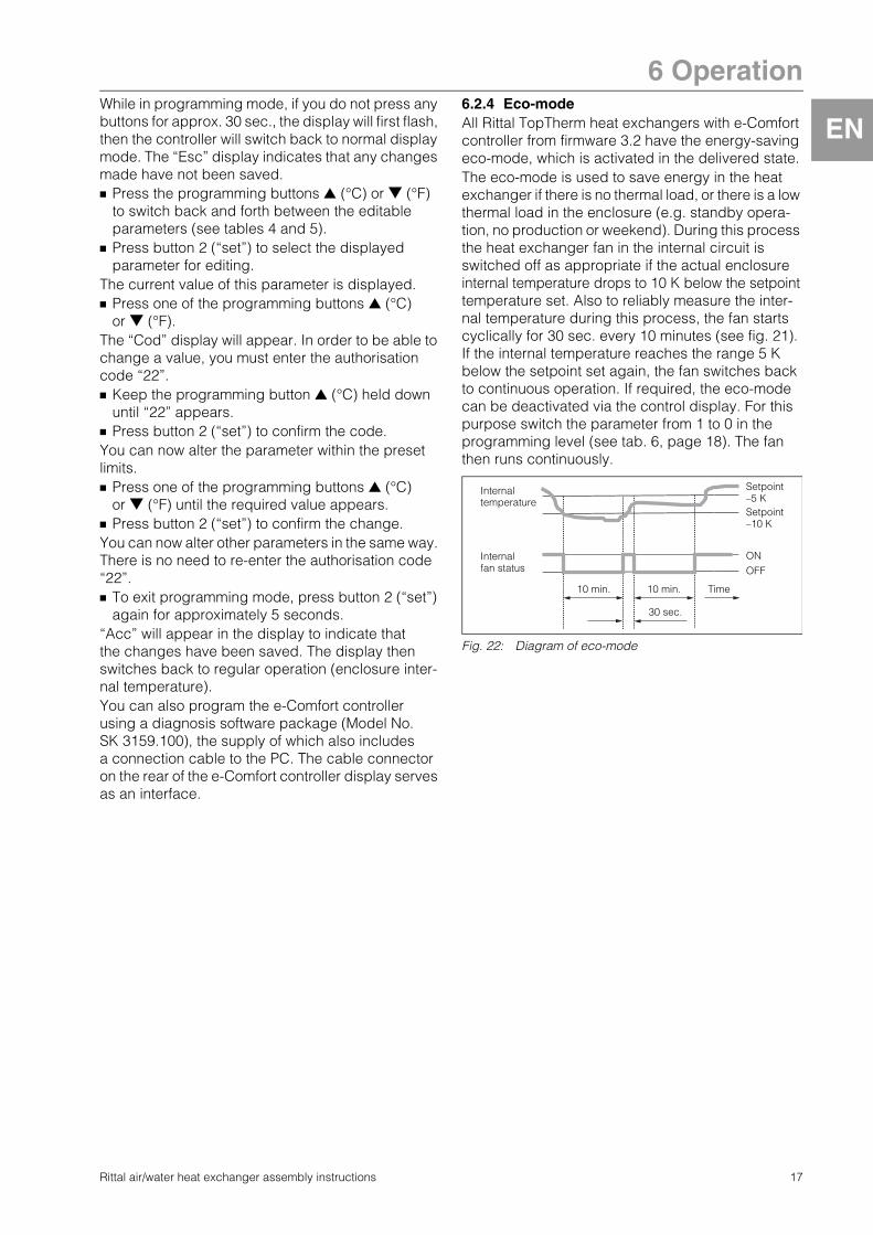
6.2.4 Eco-modeAll Rittal TopTherm heat exchangers with e-Comfort controller from firmware 3.2 have the energy-saving eco-mode, which is activated in the delivered state.The eco-mode is used to save energy in the heat exchanger if there is no thermal load, or there is a low thermal load in the enclosure (e.g. standby opera-tion, no production or weekend). During this process the heat exchanger fan in the internal circuit is switched off as appropriate if the actual enclosureinternal temperature drops to 10 K below the setpointtemperature set. Also to reliably measure the inter-nal temperature during this process, the fan starts cyclically for 30 sec. every 10 minutes (see fig. 21). If the internal temperature reaches the range 5 K below the setpoint set again, the fan switches back to continuous operation. If required, the eco-mode can be deactivated via the control display. For this purpose switch the parameter from 1 to 0 in the programming level (see tab. 6, page 18). The fan then runs continuously.
Fig. 22: Diagram of eco-mode
ONInternal fan status
Internal temperature
Time
Setpoint–5 KSetpoint–10 K
OFF
10 min.
30 sec.
10 min.
Rittal air/water heat exchanger assembly instructions 17

6 Operation
EN
6.2.5 Editable parametersSee also fig. 25 on page 20.Tab. 7: Editable parameters
Progr. level
Display screen
Parameters Min. value
Max. value
Factory setting
Description
1 St Internal enclosure temperature setpoint Ti
20 55 35 The setting of the enclosure internal temperature is preset at the factory to 35 °C and may be altered within a range of 20 – 55 °C.
2 Mod Control mode 0 1 0 Control mode setting. The temperature control is made as factory setting with the magnetic valve (0). It is, however, possible to change the temperature control by starting and stopping the internal fan (1); the magnetic valve then remains permanently open. You must obtain the manufacturer's consent before changing to control mode (1).
3 Ad Master-slave identifier
0 19 0 See “6.2.9 Setting the master-slave identifier”, page 21.
4 CF Change-over °C/°F 0 1 0 The temperature display can be switched from °C (0) to °F (1). The corresponding LED displays the current temperature unit.
5 H1 Setting for switching difference (hysteresis)
2 10 5 The air/water heat exchanger is preset in the factory to a switching hysteresis of 5 K. This parameter should only be changed in consultation with us. Please contact us for advice.
6 H2 Differential for error message A2
3 15 5 If the internal enclosure temperature exceeds the set value by more than 5 K, then error message A2 (enclosure internal temperature too high) appears on the display terminal. If necessary, the differential may be altered here within the range of 3 – 15 K.
26 ECO Eco-mode operation 0 1 1 Eco-mode OFF: 0 / Eco-mode ON: 1
18 Rittal air/water heat exchanger assembly instructions

6 Operation
EN
Rittal air/water heat exchanger assembly instructions 19
6.2.6 Bus connection (only when interconnecting several units with an e-Comfort controller)
When using several air/water heat exchangers, the serial unit interface can be used to connect up to ten air/water heat exchangers with the bus cable (Model No. SK 3124.100).
When interconnecting, please note the following:– De-energise the air/water heat exchangers to
be connected.– Ensure proper electrical insulation.– Make sure the cables are not laid in parallel to
power lines.– Make sure that the lines are short.
Fig. 23: Connection example: Master-slave operation
Key1 Serial interface2 Serial interface cable3 Master-slave bus cable (Model No. SK 3124.100)RTT Rittal TopTherm air/water heat exchangerX1 Supply connection/Door limit switch/Alarms
X2 Master-slave connection Sub-D, 9-poleX3 Serial interface Sub-D, 9-poleSt. Sub-D connector, 9-poleBu. Sub-D jack, 9-poleAdr. Address
Fig. 24: Connection example: Door limit switch and master-slave operation
Key1 Master air/water heat exchanger2 Slave air/water heat exchanger3 2-door enclosure with two door limit switches4 Enclosure with door limit switch
Note:The electrical signals at the X2 interface are of an extra-low voltage (not extra-low safety voltages in accordance with EN 60 335-1).
X2
CMC
RTTMaster
Adr.: 09
X1
X2 X3
X1
X2 X3
X1
X2 X3
X1
X2 X3
X2 X3 X2X2
X2 X2
X2
X2
St. St. St.Bu.
St.Bu.
X2
Adr.: 11 Adr.: 12RTTSlave
RTTSlave
Adr.: 19RTTSlave
St.Bu.
St.
Bu.
3
2
1
X10 L1 L2N PE 1 2 3 4 5
1
X10 X10 X10 X10 X10
X2 X2 X2 X2 X2 X2
X2
L1 PE 1 2 3 4 5 L1 L2N PE 1 2 3 4 5L2 L3 L1 PE 1 2 3 4 5L2 L3 L1 PE 1 2 3 4 5L2 L3 L1 PE 1 2 3 4 5L2 L3
L1L2 N
PE
12
34
5
X10
2 3 4 5 6
1Adr.: 06 Adr.: 11 Adr.: 12 Adr.: 13 Adr.: 14 Adr.: 15
2 2 2 2 2
3 4 4 3 2
Adr.: 16
6 Operation
EN
6.2.7 Programming overview of e-Comfort controllerFig. 25: Programming overview of e-Comfort controller
= 5
sec
.
= 5
sec
.
20 Rittal air/water heat exchanger assembly instructions

6 Operation
EN
6.2.8 Defining system messages for evaluationSystem messages are shown on the display screen of the e-Comfort controller via the displays A1 to A20 and E0.A more detailed explanation of the system messages may be found in section “6.2.10 Evaluating system messages”, page 22. See also fig. 25 on page 20.
Tab. 8: System messages which may be evaluated via relays
The system messages A01 – A20 may additionally be evaluated via two floating system message relays. In this way, one of the two system message relays may be allocated to each system message.System message relays with normally open contact, see wiring diagrams at section “4.6.5 Installing the power supply”, page 11:– Terminal 3: NO (normally open, relay 2)– Terminal 4: Connection of the supply voltage to the
system message relay– Terminal 5: NO (normally open, relay 1)
The definition NO refers to the de-energised state. As soon as power is applied to the air/water heat exchanger, both system message relays (relay 1 and 2) energise.This is the normal operating state of the air/water heat exchanger. As soon as a system message occurs or the power supply is interrupted, the corresponding relay will drop out and open the contact.
Program system messages with the value0: System message is not sent to the system
message relays, but merely appears in the display
1: System message is evaluated by relay 12: System message is evaluated by relay 2
6.2.9 Setting the master-slave identifierWhen several air/water heat exchangers are con-nected together (maximum 10), one of the air/water heat exchangers must be defined as the “master” and the others as “slaves”. For this purpose, assign a corresponding identifier (address) to each air/water heat exchanger which will enable the air/water heat exchanger to be identified in the network.If one of the slave units reaches the set temperature or if the door limit switch function is activated, the affected slave unit will report to the master unit, which then deactivates all the other air/water heat exchangers.
Progr. level
Display screen
Min. value
Max. value
Factory setting
Type or location of fault
7 A01 0 2 0 Enclosure door open
8 A02 0 2 0 Internal temperature of enclosure too high
9 A08 0 2 1 Condensate warning
10 A10 0 2 1 Fan blocked or defective
11 A16 0 2 1 Internal temperature sensor
12 A18 0 2 1 EPROM
13 A19 0 2 0 LAN/Master-Slave
14 A20 0 2 0 Voltage drop
Notes:– Only one unit may be configured as
master, and its identifier must match the number of connected slave units.
– The slave units must have different identifiers.
– The identifiers must be numbered in ascending order without any gaps.
Rittal air/water heat exchanger assembly instructions 21

6 Operation
EN
On the master air/water heat exchanger (00 = factory setting), set the number of slave units present in the network:01: Master with 1 slave air/water heat exchanger02: Master with 2 slave air/water heat exchangers03: Master with 3 slave air/water heat exchangers04: Master with 4 slave air/water heat exchangers05: Master with 5 slave air/water heat exchangers06: Master with 6 slave air/water heat exchangers07: Master with 7 slave air/water heat exchangers08: Master with 8 slave air/water heat exchangers09: Master with 9 slave air/water heat exchangersFig. 26: Master-slave connection (example)
For details of how to set the identifier, see “6.2.5 Editable parameters”, page 18 or “6.2.7 Programming overview of e-Comfort controller”, page 20, parameter “Ad”.
6.2.10 Evaluating system messagesIn the e-Comfort controller, system messages are indicated by a number in the display.
On the slave air/water heat exchanger (00 = factory setting), set its own address:11: Slave air/water heat exchanger No. 112: Slave air/water heat exchanger No. 213: Slave air/water heat exchanger No. 314: Slave air/water heat exchanger No. 415: Slave air/water heat exchanger No. 516: Slave air/water heat exchanger No. 617: Slave air/water heat exchanger No. 718: Slave air/water heat exchanger No. 819: Slave air/water heat exchanger No. 9
Tab. 9: Troubleshooting with the e-Comfort controller
Master 02
Slave 11
Slave 12
Display screen
System message Possible cause Measures to rectify the fault
A01 Enclosure door open Door open or door limit switch incorrectly positioned
Close door, position door limit switch correctly, check connection if necessary
A02 Internal temperature of enclosure too high
Cooling capacity inadequate/unit undersized Check cooling capacity
A08 Condensate warning Condensate discharge kinked or blocked
Check condensate drainage; correct any kinks or blockages in the hose
A10 Fan Blocked or defective Clear the blockage; replace if necessary
A16 Internal temperature sensor Open or short-circuit Replace
A18 EPROM error New board installed incorrectly
Software update needed (only following board installation with more recent soft-ware): Enter the programming level with Code 22; press button 1 and confirm with “set” until “Acc” appears. Next, disconnect the unit from the mains and reconnect.
A19 LAN/Master-Slave Master and slave not connected Check setting and cable
A20 Voltage drop Error display not shown Event is stored in the log file
E0 Display message
Connection problem between the display and the controller board
Reset: Switch power supply off, then switch on again after approx. 2 sec.
Cable defective; connection loose Replace the boards
22 Rittal air/water heat exchanger assembly instructions

7 Inspection and maintenance
EN
Rittal air/water heat exchanger assembly instructions 23
7 Inspection and maintenance
7.1 GeneralThe air/water heat exchanger is largely maintenance free. The water circuit is checked at the factory for leaks and subjected to a function trial run.The installed maintenance-free fan is mounted on ball bearings, protected against moisture and dust, and fitted with a temperature monitor. The life expectancy is at least 30,000 operating hours. If dirt is present in the cooling water, a filter must be fitted.Maintenance interval: 2,000 operating hours.
Sequence of maintenance measures:– Check the level of dirt.– Activate test mode; cooling function OK?– Check the noise generation of the fan.
Fig. 27: Disconnect the mains plug (X1)
Fig. 28: Remove the fastening screws for the cover with fan
Fig. 29: Remove the cover with fan
Fig. 30: Disconnect the connector from the display
8 Emptying, storage and disposal
During storage, the air/water heat exchanger must stand upright.Disposal can be performed at the Rittal plant. Please contact us for advice.
Emptying (for units with Basic controller only):During storage and transportation below freezing point, the air/water heat exchanger should be drained completely in the water supply direction using compressed air. This requires that the mag-netic valve is opened.For the e-Comfort controller, this is achieved by simultaneously pressing the H2 (°C key) and H4 (/set key) keys for 5 seconds. The magnetic valve is then opened for approximately 5 minutes.
Risk of electric shock!The unit is live. Switch off the power supply before opening, and take suitable precautions against it being accidentally switched on again.
Caution! Risk of fire! Never use flammable liquids for cleaning.
Caution! Risk of damage!The air/water heat exchanger must not be subjected to temperatures above +70 °C during storage.

9 Technical specifications
EN
9 Technical specificationsFig. 31: Rating plate (Technical specifications)
– Observe the mains connection data (voltage and frequency) as per the rating plate.
– Observe the pre-fuse as per the specifications on the rating plate.
Model No. SK
Basic controller, RAL 7035 3363.100 3363.104 3364.100 3364.104
e-Comfort controller, RAL 7035 3363.500 3363.504 3364.500 3364.504
Rated voltage V, Hz 230, 1~, 50/60
Dimensions W x H x D mm 280 x 550 x 120
Air throughput of fans (unimpeded air flow) 300 m3/h
Rated current 0.18 A/0.18 A
Pre-fuse T 4.0 A
Power consumption Pel to DIN 3168 37 W/38 W
Useful cooling output Qk to DIN 3168 L35 W10 400 l/h 500 W 1000 W 950 W
Admissible pressure 1 to 10 bar
Water inlet temperature +1 °C to +30 °C
Temperature setting range +20 °C to +55 °C
Operating temperature range +1 °C to +70 °C
Noise level 42 dB (A) 44 dB (A)
Electrical connection Plug-in terminal strip
Water connection 1/2˝ hose nozzle or G 3/8˝ external thread
Protection category to IEC 60 529 IP 55
Weight 8 kg 9 kg
.
24 Rittal air/water heat exchanger assembly instructions

9 Technical specifications
EN
Model No.Basic controller, RAL 7035 3373.100 3373.110 3373.140 3373.104 3373.114 3373.144
e-Comfort controller, RAL 7035 3373.500 3373.510 3373.540 3373.504 3373.514 3373.544
Rated voltage V, Hz 230, 1~, 50/60 115, 1~, 50/60 400, 2~, 50/60 230, 1~, 50/60 115, 1~, 50/60 400, 2~, 50/60
Dimensions W x H x D mm 400 x 950 x 145
Air throughput of fans (unimpeded air flow) 880 m3/h
Rated current 0.49 A/0.61 A 0.98 A/1.25 A 0.28 A/0.35 A 0.49 A/0.61 A 0.98 A/1.25 A 0.28 A/0.35 A
Pre-fuse T 4.0 A
Power consumption Pel to DIN 3168 110 W/140 W
Useful cooling output Qk to DIN 3168 L35 W10 400 l/h 2000 W
Admissible pressure 1 to 10 bar
Water inlet temperature +1 °C to +30 °C
Temperature setting range +20 °C to +55 °C
Operating temperature range +1 °C to +70 °C
Noise level 50 dB(A)
Electrical connection Plug-in terminal strip
Water connection 1/2˝ hose nozzle or G 3/8˝ external thread
Protection category to IEC 60 529 IP 55
Weight 20 kg 23 kg 20 kg 23 kg
.
Model No. SK
Basic controller, RAL 7035 3374.100 3374.110 3374.140 3374.104 3374.114 3374.144
e-Comfort controller, RAL 7035 3374.500 3374.510 3374.540 3374.504 3374.514 3374.544
Rated voltage V, Hz 230, 1~, 50/60 115, 1~, 50/60 400, 2~, 50/60 230, 1~, 50/60 115, 1~, 50/60 400, 2~, 50/60
Dimensions W x H x D mm 400 x 950 x 145
Air throughput of fans (unimpeded air flow) 1180 m3/h
Rated current 0.76 A/1.01 A 1.55 A/2.05 A 0.44 A/0.58 A 0.76 A/1.01 A 1.55 A/2.05 A 0.44 A/0.58 A
Pre-fuse T 4.0 A
Power consumption Pel to DIN 3168 169 W/232 W
Useful cooling output Qk to DIN 3168 L35 W10 400 l/h 3000 W 2800 W
Admissible pressure 1 to 10 bar
Water inlet temperature +1 °C to +30 °C
Temperature setting range +20 °C to +55 °C
Operating temperature range +1 °C to +70 °C
Noise level 60 dB(A)
Electrical connection Plug-in terminal strip
Water connection 1/2˝ hose nozzle or G 3/8˝ external thread
Protection category to IEC 60 529 IP 55
Weight 23 kg 26 kg 23 kg 26 kg
.
Rittal air/water heat exchanger assembly instructions 25

9 Technical specifications
EN
Model No. SKBasic controller, RAL 7035 3375.100 3375.110 3375.140 3375.104 3375.114 3375.144
e-Comfort controller, RAL 7035 3375.500 3375.510 3375.540 3375.504 3375.514 3375.544
Rated voltage V, Hz 230, 1~, 50/60 115, 1~, 50/60 400, 2~, 50/60 230, 1~, 50/60 115, 1~, 50/60 400, 2~, 50/60
Dimensions W x H x D mm 450 x 1400 x 220
Air throughput of fans (unimpeded air flow) 1450 m3/h
Rated current 0.78 A/1.01 A 1.58 A/2.1 A 0.45 A/0.59 A 0.78 A/101 A 1.58 A/2.1 A 0.45 A/0.59 A
Pre-fuse T 4.0
Power consumption Pel to DIN 3168 178 W/232 W
Useful cooling output Qk to DIN 3168 L35 W10 400 l/h 5000 W 4500 W
Admissible pressure 1 to 10 bar 1 to 10 bar
Water inlet temperature +1 °C to +30 °C +1 °C to +30 °C
Temperature setting range +20 °C to +55 °C +20 °C to +55 °C
Operating temperature range +1 °C to +70 °C +1 °C to +70 °C
Noise level 62 dB(A)
Electrical connection Plug-in terminal strip
Water connection 1/2˝ hose nozzle or G 3/8˝ external thread
Protection category to IEC 60 529 IP 55
Weight 39 kg 42 kg 39 kg 42 kg
.
26 Rittal air/water heat exchanger assembly instructions
.

10 List of spare parts
10 List of spare partsEN
Fig. 32: Spare parts for SK 3363.XXX, SK 3364.XXX
Key10 Fan, complete15 Dispatch bag32 Magnetic valve, complete33 Non-return valve (only for SK 33XX.5XX)40 Controller board55 Display71 Temperature probe73 Float-actuated switch (only for SK 33XX.5XX)75 Cover91 Heat exchanger
Fig. 33: Spare parts for SK 3373.XXX, SK 3374.XXX, SK 3375.XXX
15
55
75
40
1071
91
33
32
73
SK 3363.XXX, SK 3364.XXX
Note:As well as the spare part number, when ordering spare parts the following information must be provided:– Unit model– Fabrication number– Date of manufactureThis information may be found on the rating plate.
15
55
40
91
33
32
73
75
1071
SK 3373.XXX, SK 3374.XXX, SK 3375.XXX
.
Rittal air/water heat exchanger assembly instructions 27

11 Further technical information
EN
11 Further technical information11.1 Hydrological dataTo avoid system damage and to ensure safe operation, Rittal GmbH & Co. KG recommends the use of system water or an additive whose composition does not differ from that presented in the following summary:
Tab. 10: Hydrological data
Hydrological data Unit Model No. SK Model No. SK1)
–
3363.100/.500/3364.100/.500/3373.100/.110/.140/.500/.510/.5403374.100/.110/.140/.500/.510/.5403375.100/.110/.140/.500/.510/.540
3363.104/.5043364.104/.5043373.104/.114/.144/.504/.514/.5443374.104/.114/.144/.504/.514/.5443375.104/.114/.144/.504/.514/.544
pH value 7 – 8.5 6 – 9
Calcium hardness °dH 3 < 8 1 – 12
Free carbonic acid mg/dm3 8 – 15 1 – 100
Corresponding carbonic acid mg/dm3 8 – 15 free
Aggressive carbonic acid mg/dm3 0 0 – 400
Sulphides mg/dm3 free free
Oxygen mg/dm3 < 10 < 10
Chloride ions mg/dm3 < 50 < 200
Sulphate ions mg/dm3 < 250 < 500
Nitrates and nitrites mg/dm3 < 10 < 100
COD mg/dm3 < 7 < 40
Ammonia mg/dm3 < 5 < 20
Iron mg/dm3 < 0.2 free
Manganese mg/dm3 < 0.2 free
Conductivity μS/cm < 2200 < 4000
Evaporation residue mg/dm3 < 500 < 2000
Potassium permanganate mg/dm3 < 25 < 40
Suspended matter
mg/dm3 < 3
mg/dm3 > 3 < 15; partial current purification recommended
mg/dm3 > 15; continuous purification recommended
1) The complete absence of corrosion under experimental conditions suggests that solutions with a significantly higher salt content and greater corrosion potential (such as seawater) can still be tolerated.
.
28 Rittal air/water heat exchanger assembly instructions

11 Further technical information
EN
900 120011.2 Characteristic curves
11.2.1 Water resistance
Rittal air/water heat exchanger assembly instructions 29
Fig. 34: Water resistance SK 3363.XXX
Fig. 35: Water resistance SK 3364.XXX
Fig. 36: Water resistance SK 3373.XXX
Fig. 37: Water resistance SK 3374.XXX
Fig. 38: Water resistance SK 3375.XXX
150
300
600
10000
200 300 400
450
750
500
p
V
Δp: Water resistance [mbar]V: Volumetric flow [l/h]..
150
300
600
900
10000
200 300 400
450
750
500
p
V
Δp: Water resistance [mbar]V: Volumetric flow [l/h]..
200
400
800
1200
10000
200 300 400
600
1000
500
p
V
Δp: Water resistance [mbar]V: Volumetric flow [l/h]..
10000
200
200
400
600
800
1000
300 400 500
p
V
Δp: Water resistance [mbar]V: Volumetric flow [l/h]..
200
300
500
700
1000100
200 300 400
400
600
500
p
V
Δp: Water resistance [mbar]V: Volumetric flow [l/h]..

12 Appendix 1: Cut-out and hole sizes
EN
30 Rittal air/water heat exchanger assembly instructions
12 Appendix 1: Cut-out and hole sizes
12.1 Dimensions for external and internal mounting
Fig. 39: SK 3363.XXX/SK 3364.XXX
120 120
15
520
506
550
250
280256
550
520
4920 250
280
91
20
2525
100
2
3
1 1
Mounting cut-out for external mounting A
Mounting cut-out for internal mounting E
A E
Ø 6.5 (4x for internal and external mounting)Water connections: 1/2˝ hose nozzle or G 3/8˝ external threadCondensate discharge 1/2˝
1
2
3
A E

12 Appendix 1: Cut-out and hole sizes
EN
Rittal air/water heat exchanger assembly instructions 31
Fig. 40: SK 3373.XXX/SK 3374.XXX
350
25
350250
250350
400
255
32.5
950
920
15
145 145
264.
532
533
0.5
Min. 340
Max. 375
11
3535
100
2
3
1
1
950
920
250
250400
49
20.5
15
9140
1
1
Mounting cut-out for external mounting A
Mounting cut-out for internal mounting E
A E
Ø 6.5 (4x for internal and external mounting)Water connections: 1/2˝ hose nozzle or G 3/8˝ external threadCondensate discharge 1/2˝
1
2
3
A E

12 Appendix 1: Cut-out and hole sizes
EN
32 Rittal air/water heat exchanger assembly instructions
Fig. 41: SK 3375.XXX
5050 100
2
3
220220
1400
1365
846.
5
1520
33.5
50
450
470
350
450
420
420
350
1
1
499140
350
450
350
1400
1365
20.5
15
20
1
1
455
455
455
Min. 411
Max. 446
11
Mounting cut-out for external mounting A
Mounting cut-out for internal mounting E
A E
Ø 6.5 (4x for internal and external mounting)Water connections: 1/2˝ hose nozzle or G 3/8˝ external threadCondensate discharge 1/2˝
1
2
3
A E

EN
13 Appendix 2: Application example
13 Appendix 2: Application exampleParallel connection of 4 air/water heat exchangersExample: Parallel connection of 4 air/water heat exchangers with cold water supply via a recooling system. Overflow valves and bypass control should be integrated into the recooling system and the customer’s own pipeline system respectively.
Fig. 42: Parallel connection of 4 air/water heat exchangers
1 5
6
2 2 2 2
3
4 4 4 4
Recooling systemAir/water heat exchangerOverflow valve SK 3301.900/.910/.920 (bypass function with closed magnetic valve of the air/water heat exchanger)Flow regulator valve SK 3301.930/.940 (to regulate the volume flow in air/water heat exchangers)Non-return valve (optional)Magnetic valve (optional)
1
2
3
4
5
6
Rittal air/water heat exchanger assembly instructions 33

3rd
ed
ition
11.2
012
/ ID
no.
315
410
� Enclosures� Power Distribution� Climate Control� IT Infrastructure� Software & Services
RITTAL GmbH & Co. KG Postfach 1662 · D-35726 HerbornPhone +49(0)2772 505-0 · Fax +49(0)2772 505-2319 E-mail: [email protected] · www.rittal.com
Recommended