GSM Association Non-confidential
Official Document IR.88 - LTE Roaming Guidelines
V10.0 Page 1 of 68
LTE and EPC Roaming Guidelines
Version 10.0
10 July 2013
This is a Non-binding Permanent Reference Document of the GSMA
Security Classification: Non-confidential Access to and distribution of this document is restricted to the persons permitted by the security classification. This document is confidential to the
Association and is subject to copyright protection. This document is to be used only for the purposes for which it has been supplied and
information contained in it must not be disclosed or in any other way made available, in whole or in part, to persons other than those permitted
under the security classification without the prior written approval of the Association.
Copyright Notice
Copyright © 2013 GSM Association
Disclaimer
The GSM Association (“Association”) makes no representation, warranty or undertaking (express or implied) with respect to and does not accept
any responsibility for, and hereby disclaims liability for the accuracy or completeness or timeliness of the information contained in this document.
The information contained in this document may be subject to change without prior notice.
Antitrust Notice
The information contain herein is in full compliance with the GSM Association’s antitrust compliance policy.
GSM Association Non-confidential
Official Document IR.88 - LTE and EPC Roaming Guidelines
V9.0 Page 2 of 68
Table of Contents
LTE Roaming Guidelines ................................................................................1
Version 9.0 ........................................................................................................1
24 January 2013 ...............................................................................................1
1 Introduction .............................................................................................5
1.1 Overview .............................................................................................5
1.2 Scope ..................................................................................................5
1.3 Definition of Terms ..............................................................................5
1.4 Document Cross-References ..............................................................7
2 Architecture .............................................................................................9
2.1 Architecture Models ............................................................................9
2.2 Interfaces .......................................................................................... 11
2.3 Features ............................................................................................ 12
2.3.1. SGs Interface for CS Fallback and SMS over SGs ........................... 12
3 Technical Requirements and Recommendations for Interfaces....... 12
3.1 General requirements for Inter-PMN interfaces ................................ 12
3.1.1 Inter-PMN IP backbone network requirements ................................. 12
3.1.2 Stream Control Transmission Protocol (SCTP)................................. 13 3.1.2.1 Introduction .................................................................................... 13 3.1.2.2 SCTP Parameters ........................................................................... 13
3.1.3 Diameter ........................................................................................... 15 3.1.3.1 Introduction .................................................................................... 15 3.1.3.2 Diameter Agents ............................................................................ 15 3.1.3.3 End to End Diameter Architecture ................................................ 16 3.1.3.4 Diameter Routing ........................................................................... 17 3.1.3.5 Diameter Transport Parameter ...................................................... 18 3.1.3.6 Notification of ME Identity ............................................................. 18 3.1.3.7 QoS for Diameter messages ......................................................... 18
3.2 S8 Interface....................................................................................... 19
3.2.1 Procedures........................................................................................ 19 3.2.1.1 General ........................................................................................... 19 3.2.1.2 SGW Selection ............................................................................... 20 3.2.1.3 PGW Selection ............................................................................... 20
3.2.2 GTP .................................................................................................. 21
3.2.3 PMIP ................................................................................................. 21
3.2.4 PMIP-GTP Interworking .................................................................... 21
3.3 S9 Interface....................................................................................... 21
3.3.1 S9 implementation requirements ...................................................... 21
3.3.2 Guidelines for Diameter interface over S9 interface .......................... 22
3.4 S6a and S6d interface ...................................................................... 22
4 Technical Requirements and Recommendations for Legacy Interworking and Coexistence ............................................................................................ 22
4.1 Legacy Interworking scenarios.......................................................... 22
4.1.1 Introduction ....................................................................................... 22
4.1.2 VPMN has not implemented LTE ...................................................... 22
GSM Association Non-confidential
Official Document IR.88 - LTE and EPC Roaming Guidelines
V9.0 Page 3 of 68
4.1.3 HPMN has not implemented LTE ...................................................... 24
4.2 Co-existence scenarios ..................................................................... 25
4.2.1 Introduction ....................................................................................... 25
4.2.2 Possible scenarios ............................................................................ 26 4.2.2.1 2G/3G Roaming Agreement Only .................................................. 26 4.2.2.2 2G/3G and LTE Roaming Agreement ............................................ 27
4.2.3 Consequences of different APN approaches when roaming ............. 29 4.2.3.1 Consequences of the single APN approach when roaming ....... 29 4.2.3.2 Consequences of the dual APN approach when roaming .......... 31 4.2.3.3 Guidance regarding the APN approach when roaming ............... 32
4.3 Inter-RAT Handover .......................................................................... 32
4.3.1 Handover to/from 2G/3G and LTE .................................................... 32 4.3.1.1 Introduction .................................................................................... 32 4.3.1.2 Handover restriction to/from 2G/3G and LTE (Active mode) ...... 32 4.3.1.3 Handover restriction to/from 2G/3G and LTE (Idle mode) ........... 34
4.3.2 Handover to/from non-3GPP accesses and LTE .............................. 34
5 Technical Requirements and Recommendations for Services ......... 34
5.1 Short Message Service (SMS) .......................................................... 34
5.1.1 SMS over SGs .................................................................................. 34
5.2 Voice ................................................................................................. 35
5.2.1 CS Fallback....................................................................................... 35 5.2.1.1 General .......................................................................................... 35 5.2.1.2 Roaming Retry for CSFB procedure ............................................. 36 5.2.1.3 Roaming Forwarding for CSFB procedure ................................... 38 5.2.1.3 Coexistence of Roaming Forwarding and Roaming Retry procedures ........................................................................................................ 38 5.2.1.4 Recommended procedures ........................................................... 38
5.2.2 LTE Voice Roaming Architecture ...................................................... 39
5.2.3 HSPA Voice Roaming Architecture ................................................... 39
6 Other Technical Requirements and Recommendations .................... 39
6.1 Access Control .................................................................................. 39 6.1.1 Access Control in the VPMN ......................................................... 39 6.1.2 Access Control in the HPMN ......................................................... 40 6.1.3 Access Control in the VPMN for CS Fallback .............................. 40
6.2 Addressing ........................................................................................ 41
6.2.1 UE Addressing .................................................................................. 41 6.2.1.1 SS7 .................................................................................................. 41 6.2.1.2 IP ..................................................................................................... 41
6.2.2 Network Element Addressing ............................................................ 42 6.2.2.1 IP and SS7 ...................................................................................... 42 6.2.2.2 Fully Qualified Domain Names (FQDNs) ...................................... 42 6.2.2.3 Diameter Realms ............................................................................ 42
6.3 APN for IMS based services ............................................................. 42 6.3.1 Introduction .................................................................................... 42 6.3.2 Definition of the IMS well-known APN .......................................... 43 6.3.3 Gateway Selection ......................................................................... 43
6.3.4 Disconnect the PDN connection to the IMS APN and inter-PLMN roaming .......................................................................................................... 43
6.3.5 APN for XCAP/Ut .............................................................................. 44
GSM Association Non-confidential
Official Document IR.88 - LTE and EPC Roaming Guidelines
V9.0 Page 4 of 68
6.3.6 Network-initiated deactivation and re-activation of the PDN connection to the IMS APN ................................................................................................ 44
6.4 Emergency PDN connection ............................................................. 44
6.5 Security ............................................................................................. 44
6.5.0 GTP Firewall ..................................................................................... 45
6.5.1 Diameter Security ............................................................................. 46 6.5.1.1 Network Domain Security for IP – IPSec ...................................... 46 6.5.1.2 Application Layer Security ............................................................ 48 6.5.1.3 Application Layer Security ............................................................ 49 6.5.1.4 Cross-Layer Security ..................................................................... 51 6.5.2.5 Discovery of Peer PLMN Network Elements ................................ 52
6.6 Hubbing ............................................................................................ 52
6.7 Default APN ...................................................................................... 52
6A Technical Requirements for static QoS support .............................. 54
6A.1 Home Routed architecture and S8 protocol is GTP .......................... 54
6A.1.1 Limiting QoS for inbound roamers to the limits of the roaming agreement .......................................................................................................... 54
6A.1.1.1 Requirements for the VPMN .......................................................... 54 6A.1.1.2 Requirements for the HPMN ......................................................... 54 6A.1.2 Enforcement of QoS by the VPMN ................................................ 55
7 Technical Requirements for Dynamic Policy and Charging Control 55
7.1 Home Routed architecture and S8 protocol is GTP .......................... 55 7.1.1 Bearer management procedures for dynamic policy and charging control ........................................................................................................ 56
7.1.2 Limiting QoS for inbound roamers to the limits of the roaming agreement .......................................................................................................... 57
7.1.2.1 Requirements for the VPMN .......................................................... 57 7.1.2.2 Requirements for the HPMN ......................................................... 57
7.1.3 Enforcement of QoS by the VPMN ................................................... 57
7.2 Home Routed architecture and S8 protocol is PMIP ......................... 58
7.3 Local Break Out architecture............................................................. 58
Annex A: Testing Framework ....................................................................... 59
Annex B: Diameter Architecture Implementation ....................................... 60
Annex C: Background on Security Requirements ...................................... 64
Annex D: Document Management ................................................................ 65
Document History ......................................................................................... 65
Other Information ......................................................................................... 68
GSM Association Non-confidential
Official Document IR.88 - LTE and EPC Roaming Guidelines
V9.0 Page 5 of 68
1 Introduction
1.1 Overview
This document aims to provide a standardised view on how Long Term Evolution (LTE) and
Evolved Packet Core (EPC) networks can interwork in order to provide "Next Generation
Mobile Network" capabilities when users roam onto a network different from their HPMN.
Expectations of the "Next Generation Mobile Network" capabilities are described in the
GSMA Project Document: Next Generation Roaming and Interoperability (NGRAI) Project
Scope White Paper [16].
There is much commonality between existing "Data" roaming using General Packet Radio
Service (GPRS) and the capabilities and dependencies of LTE and EPC. Consequently this
document makes references to current 3GPP specifications for GPRS in addition to those
specifying solely LTE-Evolved Packet System (EPS) and EPC aspects, and also to other
GSMA IREG PRDs. The main focus is to describe EPC over LTE, since the LTE access
specifics are not covered in any other PRD. EPC over 2G/3G is also covered regarding the
EPC aspects impacting the S4-SGSN and the Gn/Gp SGSN; the 2G/3G access specific
aspects are covered in GSMA PRD IR.33 [10].
Throughout this PRD, the term "GPRS" is used to denote both 2G GPRS and 3G Packet
Switched (PS) service.
1.2 Scope
This PRD presents material about LTE and EPC Roaming. The document addresses
aspects which are new and incremental to EPC roaming in general, and using LTE access
specifically: It recognises that much of the data-roaming infrastructure is reused from GPRS
and High-Speed Packet Access (HSPA) Roaming, and for which information and
specification is found in other PRDs.
This PRD also covers Voice and SMS services using CS Fallback (CSFB) [25] and VoLTE
[30]. For VoLTE [30], only the technical guidelines in Evolved Packet Core (EPC) layer are
covered.
NOTE: This version of the PRD only covers LTE and EPC roaming over 3GPP access.
Roaming from non-3GPP access is not supported in this version of the document.
1.3 Definition of Terms
Term Description
ACL Access Control List
ARP Allocation Retention Priority
BBERF Bearer Binding and Event Reporting Function
BG Border Gateway
CER Capabilities-Exchange-Request
CEA Capabilities-Exchange-Answer
CSFB Circuit Switched FallBack
GSM Association Non-confidential
Official Document IR.88 - LTE and EPC Roaming Guidelines
V9.0 Page 6 of 68
DDoS Distributred Denial of Service
DEA Diameter Edge Agent
DNS Domain Name System
DNSSEC Domain Name System Security Extentions
DoS Denial of Service
DRA Diameter Routing Agent
EPC Evolved Packet Core
EPS Evolved Packet System (Core)
ESP Encapsulated Security Payload
E-UTRAN Evolved Universal Terrestrial Radio Access Network
GBR Guaranteed Bit Rate
GMSC Gateway MSC
GPRS General Packet Radio Service
GTP GPRS Tunnelling Protocol
HLR Home Location Register
HPMN Home Public Mobile Network
IMEI International Mobile Equipment Identifier
IMEISV IMEI Software Version
HSS Home Subscriber Server
IKE Internet Key Exchange
IP-CAN IP Connectivity Access Network
LA Location Area
LTE Long Term Evolution (Radio)
MAP Mobile Application Part (protocol)
MME Mobility Management Entity
MSC Mobile services Switching Centre
MTC Mobile Terminating Call
OCS Online Charging System
PCC Policy and Charging Control
PCEF Policy and Charging Enforcement Function
PCRF Policy and Charging Rules Function
P-CSCF Proxy Call Session Control Function
PGW PDN (Packet Data Network) Gateway
PMIP Proxy Mobile IP
QCI QoS Class Identifier
RAT Radio Access Technology
RR Resource Record
GSM Association Non-confidential
Official Document IR.88 - LTE and EPC Roaming Guidelines
V9.0 Page 7 of 68
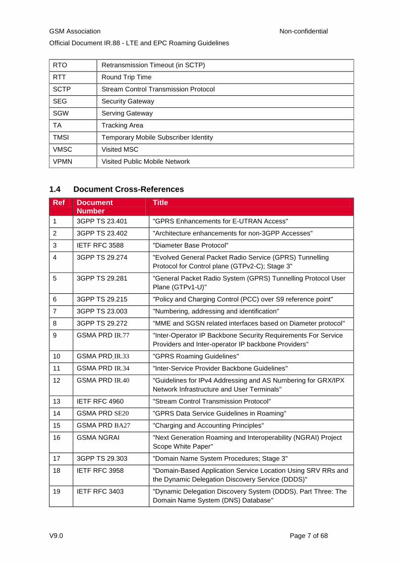
RTO Retransmission Timeout (in SCTP)
RTT Round Trip Time
SCTP Stream Control Transmission Protocol
SEG Security Gateway
SGW Serving Gateway
TA Tracking Area
TMSI Temporary Mobile Subscriber Identity
VMSC Visited MSC
VPMN Visited Public Mobile Network
1.4 Document Cross-References
Ref Document Number
Title
1 3GPP TS 23.401 "GPRS Enhancements for E-UTRAN Access"
2 3GPP TS 23.402 "Architecture enhancements for non-3GPP Accesses"
3 IETF RFC 3588 "Diameter Base Protocol"
4 3GPP TS 29.274 "Evolved General Packet Radio Service (GPRS) Tunnelling
Protocol for Control plane (GTPv2-C); Stage 3"
5 3GPP TS 29.281 "General Packet Radio System (GPRS) Tunnelling Protocol User
Plane (GTPv1-U)"
6 3GPP TS 29.215 "Policy and Charging Control (PCC) over S9 reference point"
7 3GPP TS 23.003 "Numbering, addressing and identification"
8 3GPP TS 29.272 "MME and SGSN related interfaces based on Diameter protocol"
9 GSMA PRD IR.77 "Inter-Operator IP Backbone Security Requirements For Service
Providers and Inter-operator IP backbone Providers"
10 GSMA PRD IR.33 "GPRS Roaming Guidelines"
11 GSMA PRD IR.34 "Inter-Service Provider Backbone Guidelines"
12 GSMA PRD IR.40 "Guidelines for IPv4 Addressing and AS Numbering for GRX/IPX
Network Infrastructure and User Terminals"
13 IETF RFC 4960 "Stream Control Transmission Protocol"
14 GSMA PRD SE20 "GPRS Data Service Guidelines in Roaming"
15 GSMA PRD BA27 "Charging and Accounting Principles"
16 GSMA NGRAI "Next Generation Roaming and Interoperability (NGRAI) Project
Scope White Paper"
17 3GPP TS 29.303 "Domain Name System Procedures; Stage 3"
18 IETF RFC 3958 "Domain-Based Application Service Location Using SRV RRs and
the Dynamic Delegation Discovery Service (DDDS)"
19 IETF RFC 3403 "Dynamic Delegation Discovery System (DDDS). Part Three: The
Domain Name System (DNS) Database"
GSM Association Non-confidential
Official Document IR.88 - LTE and EPC Roaming Guidelines
V9.0 Page 8 of 68
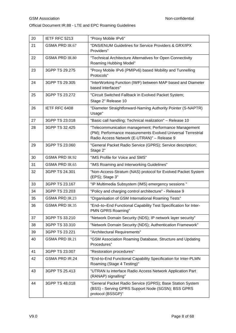
20 IETF RFC 5213 "Proxy Mobile IPv6"
21 GSMA PRD IR.67 "DNS/ENUM Guidelines for Service Providers & GRX/IPX
Providers"
22 GSMA PRD IR.80 "Technical Architecture Alternatives for Open Connectivity
Roaming Hubbing Model"
23 3GPP TS 29.275 "Proxy Mobile IPv6 (PMIPv6) based Mobility and Tunnelling
Protocols"
24 3GPP TS 29.305 "InterWorking Function (IWF) between MAP based and Diameter
based interfaces"
25 3GPP TS 23.272 "Circuit Switched Fallback in Evolved Packet System;
Stage 2" Release 10
26 IETF RFC 6408 "Diameter Straightforward-Naming Authority Pointer (S-NAPTR)
Usage"
27 3GPP TS 23.018 "Basic call handling; Technical realization" – Release 10
28 3GPP TS 32.425 "Telecommunication management; Performance Management
(PM); Performance measurements Evolved Universal Terrestrial
Radio Access Network (E-UTRAN)" – Release 9
29 3GPP TS 23.060 "General Packet Radio Service (GPRS); Service description;
Stage 2"
30 GSMA PRD IR.92 "IMS Profile for Voice and SMS"
31 GSMA PRD IR.65 "IMS Roaming and Interworking Guidelines"
32 3GPP TS 24.301 "Non-Access-Stratum (NAS) protocol for Evolved Packet System
(EPS); Stage 3"
33 3GPP TS 23.167 "IP Multimedia Subsystem (IMS) emergency sessions "
34 3GPP TS 23.203 "Policy and charging control architecture" - Release 9
35 GSMA PRD IR.23 "Organisation of GSM International Roaming Tests"
36 GSMA PRD IR.35 "End–to–End Functional Capability Test Specification for Inter-
PMN GPRS Roaming"
37 3GPP TS 33.210 "Network Domain Security (NDS); IP network layer security"
38 3GPP TS 33.310 "Network Domain Security (NDS); Authentication Framework"
39 3GPP TS 23.221 "Architectural Requirements"
40 GSMA PRD IR.21 “GSM Association Roaming Database, Structure and Updating
Procedures”
41 3GPP TS 23.007 "Restoration procedures"
42 GSMA PRD IR.24 "End-to-End Functional Capability Specification for Inter-PLMN
Roaming (Stage 4 Testing)"
43 3GPP TS 25.413 "UTRAN Iu interface Radio Access Network Application Part
(RANAP) signalling"
44 3GPP TS 48.018 "General Packet Radio Service (GPRS); Base Station System
(BSS) - Serving GPRS Support Node (SGSN); BSS GPRS
protocol (BSSGP)"
GSM Association Non-confidential
Official Document IR.88 - LTE and EPC Roaming Guidelines
V9.0 Page 9 of 68
45 3GPP TS 36.413 "Evolved Universal Terrestrial Radio Access Network (E-UTRAN);
S1 Application Protocol (S1AP)"
46 3GPP TS 29.002 "Mobile Application Part (MAP) specification"
2 Architecture
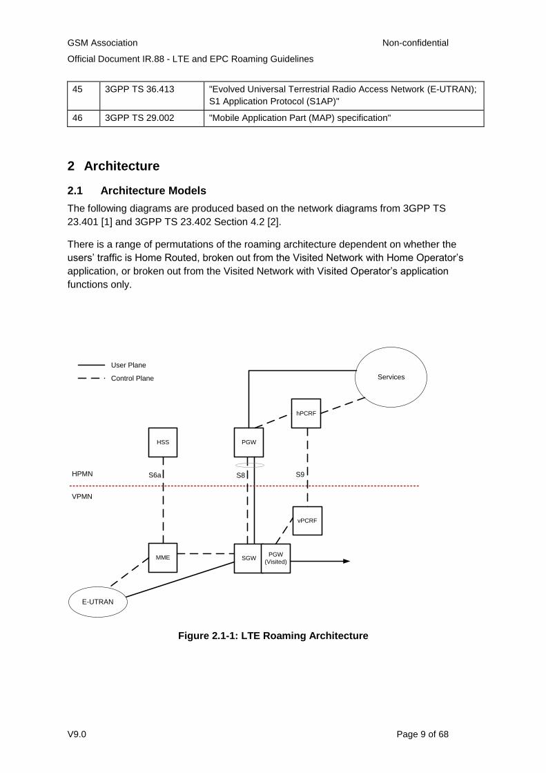
2.1 Architecture Models
The following diagrams are produced based on the network diagrams from 3GPP TS
23.401 [1] and 3GPP TS 23.402 Section 4.2 [2].
There is a range of permutations of the roaming architecture dependent on whether the
users’ traffic is Home Routed, broken out from the Visited Network with Home Operator’s
application, or broken out from the Visited Network with Visited Operator’s application
functions only.
Services
HSS
MME
PGW
hPCRF
S6a S8
VPMN
HPMN
E-UTRAN
User Plane
Control Plane
SGW
S9
PGW
(Visited)
vPCRF
Figure 2.1-1: LTE Roaming Architecture
GSM Association Non-confidential
Official Document IR.88 - LTE and EPC Roaming Guidelines
V9.0 Page 10 of 68
Services
HSS PGW
hPCRF
S8
VPMN
HPMN
User Plane
Control Plane
SGW
S9
PGW
(Visited)
vPCRF
S6d
S4
SGSN
GERAN /
UTRAN
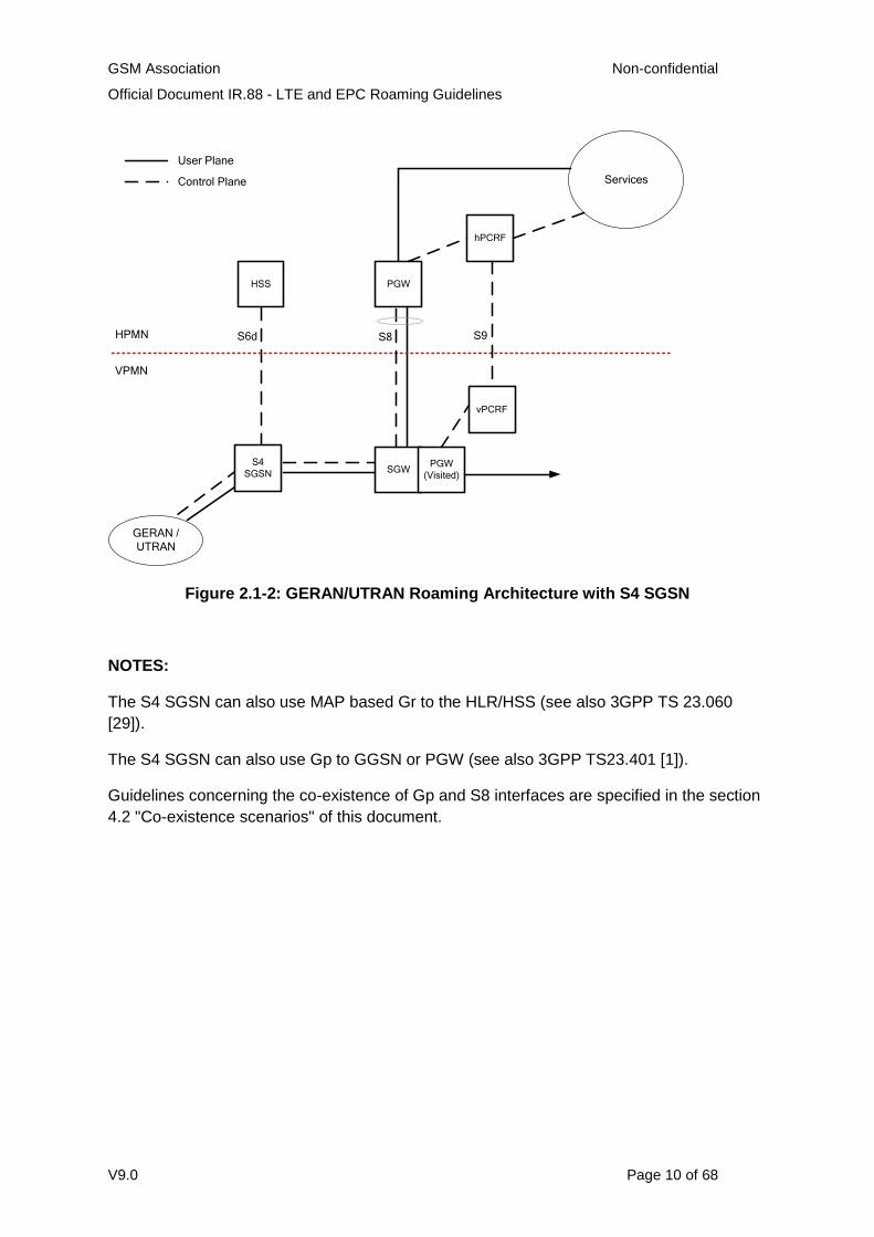
Figure 2.1-2: GERAN/UTRAN Roaming Architecture with S4 SGSN
NOTES:
The S4 SGSN can also use MAP based Gr to the HLR/HSS (see also 3GPP TS 23.060
[29]).
The S4 SGSN can also use Gp to GGSN or PGW (see also 3GPP TS23.401 [1]).
Guidelines concerning the co-existence of Gp and S8 interfaces are specified in the section
4.2 "Co-existence scenarios" of this document.
GSM Association Non-confidential
Official Document IR.88 - LTE and EPC Roaming Guidelines
V9.0 Page 11 of 68
Services
HSS PGW
hPCRF
VPMN
HPMN
User Plane
Control Plane
S9
PGW
(Visited)
vPCRF
Gr
Gn/Gp
SGSN
Gp
GERAN /
UTRAN
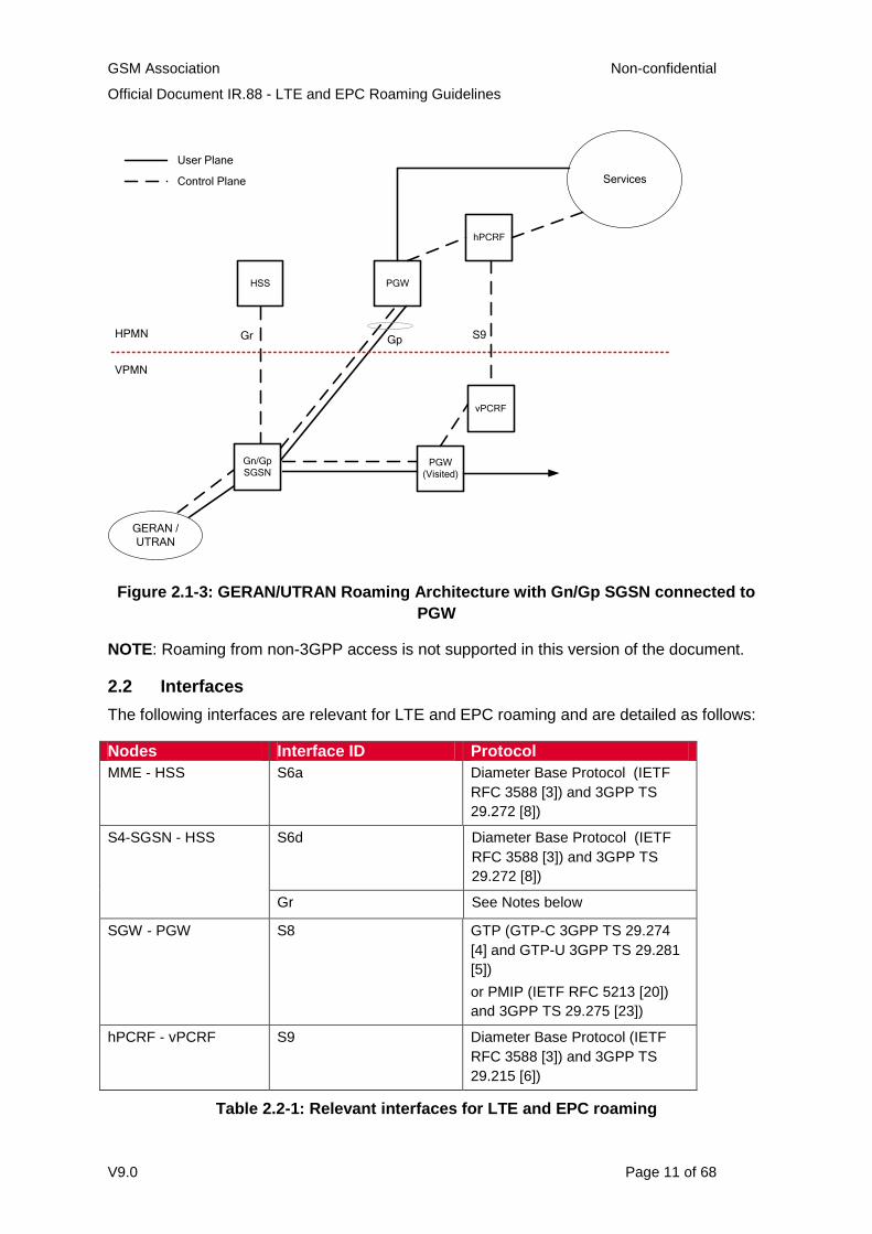
Figure 2.1-3: GERAN/UTRAN Roaming Architecture with Gn/Gp SGSN connected to
PGW
NOTE: Roaming from non-3GPP access is not supported in this version of the document.
2.2 Interfaces
The following interfaces are relevant for LTE and EPC roaming and are detailed as follows:
Nodes Interface ID Protocol
MME - HSS S6a Diameter Base Protocol (IETF
RFC 3588 [3]) and 3GPP TS
29.272 [8])
S4-SGSN - HSS S6d Diameter Base Protocol (IETF
RFC 3588 [3]) and 3GPP TS
29.272 [8])
Gr See Notes below
SGW - PGW S8 GTP (GTP-C 3GPP TS 29.274
[4] and GTP-U 3GPP TS 29.281
[5])
or PMIP (IETF RFC 5213 [20])
and 3GPP TS 29.275 [23])
hPCRF - vPCRF S9 Diameter Base Protocol (IETF
RFC 3588 [3]) and 3GPP TS
29.215 [6])
Table 2.2-1: Relevant interfaces for LTE and EPC roaming
GSM Association Non-confidential
Official Document IR.88 - LTE and EPC Roaming Guidelines
V9.0 Page 12 of 68
NOTES:
For Gr and Gp interfaces, see GSMA PRD IR.33 [10].
For co-existence of Gp and S8 interfaces, see section 4.2 "Co-existence scenarios"
of this document.
The procedures and message flows for all the above interfaces are described in
3GPP TS 23.401 [1] and 3GPP TS 23.402 [2].
The Serving GPRS Support Node - Home Subscriber Server (SGSN – HSS)
interface may be either S6d (Diameter) or Gr (MAP), depending on co-platform
legacy situation.
The inter-PMN Domain Name System (DNS) communications interface (used by the
SGSN to find a Gateway GPRS Support Node (GGSN) and by MME/SGSN to find a
PGW) uses standard DNS procedures and protocol, as specified in IETF RFC 1034
[5] and IETF RFC 1035 [6].
The charging requirements for LTE in a roaming environment are detailed in GSMA PRD
BA.27 [15].
2.3 Features
2.3.1. SGs Interface for CS Fallback and SMS over SGs
A VPMN with LTE plus GSM and/or UMTS access(es) must support the SGs interface as
defined in 3GPP TS 23.272 [25] for supporting CS Fallback and SMS over SGs for its
inbound roamers. The details of how the SGs interface is used are described in Section 5.1
and Section 5.2 of the present document.
3 Technical Requirements and Recommendations for Interfaces
3.1 General requirements for Inter-PMN interfaces
3.1.1 Inter-PMN IP backbone network requirements
The requirements for IP addressing and routing are contained within GSMA PRD IR.33 [10],
GSMA PRD IR.34 [11] and GSMA PRD IR.40 [12]. In addition, the GRX/IPX DNS (as per
PRD IR.67 [21]) is used.
It is considered that the GRX/IPX is a trusted environment and therefore there is no need for
additional security functions over and above those specified in this document and in GSMA
PRD IR.34 [11].
GSM Association Non-confidential
Official Document IR.88 - LTE and EPC Roaming Guidelines
V9.0 Page 13 of 68
3.1.2 Stream Control Transmission Protocol (SCTP)
3.1.2.1 Introduction
The Stream Control Transmission Protocol (SCTP), as defined in IETF RFC 4960 [13], is
specified for the transport of the Diameter Base Protocol (IETF RFC 3588 [3]) in 3GPP TS
29.272 [8].
SCTP was originally designed to transport Public Switched Telephone Network (PSTN)
signalling messages over IP networks, but is recognised by the IETF as being capable of
broader usage.
SCTP is a reliable transport protocol operating on top of a connection-less packet switched
network protocol such as IP. It offers the following services to its users:
1. acknowledged error-free non-duplicated transfer of user data,
2. data fragmentation to conform to discovered path MTU size,
3. sequenced delivery of user messages within multiple streams, with an option for
order-of-arrival delivery of individual user messages,
4. optional bundling of multiple user messages into a single SCTP packet,
5. network-level fault tolerance through supporting of multi-homing at either or both
ends of an association.
The design of SCTP includes appropriate congestion avoidance behaviour, and a
resistance to flooding and masquerade attacks.
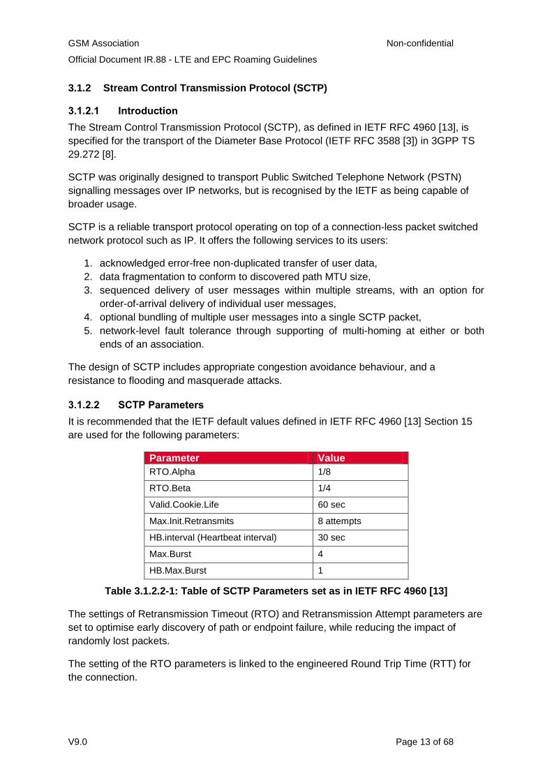
3.1.2.2 SCTP Parameters
It is recommended that the IETF default values defined in IETF RFC 4960 [13] Section 15
are used for the following parameters:
Parameter Value
RTO.Alpha 1/8
RTO.Beta 1/4
Valid.Cookie.Life 60 sec
Max.Init.Retransmits 8 attempts
HB.interval (Heartbeat interval) 30 sec
Max.Burst 4
HB.Max.Burst 1
Table 3.1.2.2-1: Table of SCTP Parameters set as in IETF RFC 4960 [13]
The settings of Retransmission Timeout (RTO) and Retransmission Attempt parameters are
set to optimise early discovery of path or endpoint failure, while reducing the impact of
randomly lost packets.
The setting of the RTO parameters is linked to the engineered Round Trip Time (RTT) for
the connection.
GSM Association Non-confidential
Official Document IR.88 - LTE and EPC Roaming Guidelines
V9.0 Page 14 of 68
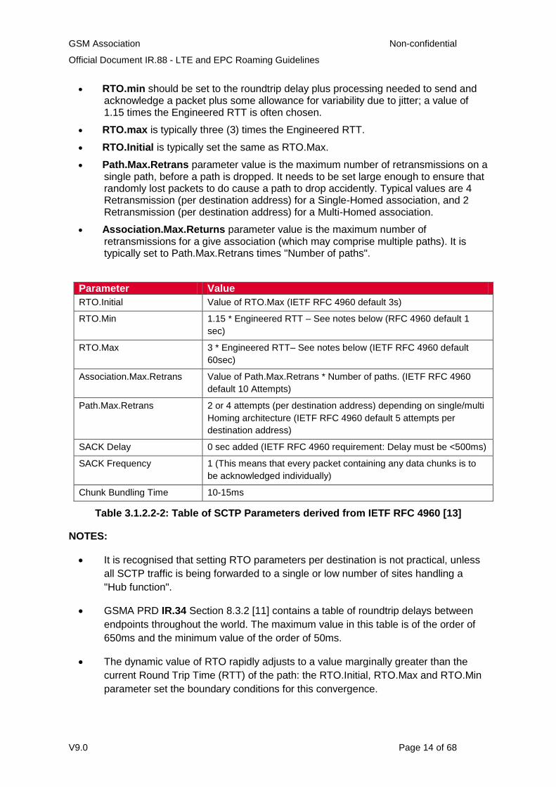
RTO.min should be set to the roundtrip delay plus processing needed to send and acknowledge a packet plus some allowance for variability due to jitter; a value of 1.15 times the Engineered RTT is often chosen.
RTO.max is typically three (3) times the Engineered RTT.
RTO.Initial is typically set the same as RTO.Max.
Path.Max.Retrans parameter value is the maximum number of retransmissions on a single path, before a path is dropped. It needs to be set large enough to ensure that randomly lost packets to do cause a path to drop accidently. Typical values are 4 Retransmission (per destination address) for a Single-Homed association, and 2 Retransmission (per destination address) for a Multi-Homed association.
Association.Max.Returns parameter value is the maximum number of retransmissions for a give association (which may comprise multiple paths). It is typically set to Path.Max.Retrans times "Number of paths".
Parameter Value
RTO.Initial Value of RTO.Max (IETF RFC 4960 default 3s)
RTO.Min 1.15 * Engineered RTT – See notes below (RFC 4960 default 1
sec)
RTO.Max 3 * Engineered RTT– See notes below (IETF RFC 4960 default
60sec)
Association.Max.Retrans Value of Path.Max.Retrans * Number of paths. (IETF RFC 4960
default 10 Attempts)
Path.Max.Retrans 2 or 4 attempts (per destination address) depending on single/multi
Homing architecture (IETF RFC 4960 default 5 attempts per
destination address)
SACK Delay 0 sec added (IETF RFC 4960 requirement: Delay must be <500ms)
SACK Frequency 1 (This means that every packet containing any data chunks is to
be acknowledged individually)
Chunk Bundling Time 10-15ms
Table 3.1.2.2-2: Table of SCTP Parameters derived from IETF RFC 4960 [13]
NOTES:
It is recognised that setting RTO parameters per destination is not practical, unless
all SCTP traffic is being forwarded to a single or low number of sites handling a
"Hub function".
GSMA PRD IR.34 Section 8.3.2 [11] contains a table of roundtrip delays between
endpoints throughout the world. The maximum value in this table is of the order of
650ms and the minimum value of the order of 50ms.
The dynamic value of RTO rapidly adjusts to a value marginally greater than the
current Round Trip Time (RTT) of the path: the RTO.Initial, RTO.Max and RTO.Min
parameter set the boundary conditions for this convergence.
GSM Association Non-confidential
Official Document IR.88 - LTE and EPC Roaming Guidelines
V9.0 Page 15 of 68
Accordingly if it is desired to choose a set of universal values for all destinations,
then the values of RTO.Max and RTO.Initial should be 2 sec, and the value for
RTO.Min should be set to 60ms. Further experience with the use of SCTP over the
GRX/IPX is needed to assess the benefits of tuning RTO parameters.
3.1.3 Diameter
3.1.3.1 Introduction
3GPP TS 23.401 [1] and TS 23.402 [2] define a direct Diameter interface between the
network elements of the visited network (Mobility Management Entity (MME), Visited Policy
and Charging Rules Function (vPCRF) and SGSN) and the network elements of the home
Network (HSS and Home Policy and Charging Rules Function (hPCRF)). Diameter Base
Protocol (IETF RFC 3588 [3]) defines the function of Diameter Agents. Diameter Extended
NAPTR (IETF RFC 6408 [26]) defines enhancements to the Diameter Routing mechanisms.
3.1.3.2 Diameter Agents
In order to support scalability, resilience and maintainability, and to reduce the export of
network topologies, the use of a PMN-edge Diameter agent is strongly recommended. The
Diameter agent is named Diameter Edge Agent(DEA) hereafter. The DEA is considered
as the only point of contact into and out of an operator’s network at the Diameter application
level. For network level connectivity see Section 3.1.1.
The Diameter Base Protocol [3] defines four types of Diameter agent, namely Diameter
Relay agent, Diameter Proxy agent, Diameter Redirect agent and Diameter Translation
agent. For signalling in LTE Roaming only the Relay agent and the Proxy agent are
relevant.
"Diameter Relay" is a function specialised in forwarding Diameter messages.
A Relay agent does NOT inspect the actual contents of the message.
When a Relay agent receives a request, it will route messages to other Diameter nodes based on information found in the message, for example, Application ID and Destination-Realm. A routing table (Realm Routing Table) is looked up to find the next-hop Diameter peer.
"Diameter Proxy" includes the functions of Diameter Relay and the following in addition:
The biggest difference from Diameter Relay is that a Diameter Proxy CAN process non-routing related AVPs. In other words, a Diameter Proxy can actually process messages for certain Diameter applications.
Therefore, a Diameter Proxy CAN inspects the actual contents of the message to perform admission control, policy control, add special information elements (AVP) handling.
According to its Realm Routing Table, a DEA can act as a Proxy for some Diameter
applications (that is add/drop/modify AVP, perform AVP inspection, and so on.) while acting
as a Relay for all others (that is simply route messages based on Application ID and
GSM Association Non-confidential
Official Document IR.88 - LTE and EPC Roaming Guidelines
V9.0 Page 16 of 68
Destination-Realm). However, one Diameter equipment can only advertise itself as one type
of Agent to one Diameter peer.
It is recommended that the DEA advertises the Relay application ID to the outer Diameter
peers. By using the Relay, inter PMN routing is independent from inner domain applications.
Note that the DEA is free to advertise the Proxy ID to inner Diameter peers.
It is therefore recommended that any DEA is able to relay or proxy all applications
supported by the PMN to inner proxies, inner relays or inner destination agents.
However, if the above mentioned recommendations cannot be implemented by PMN, the
PMN may outsource the deployment of Diameter Relay to IPX.
It is strongly recommended to deploy Diameter proxies for each Diameter application
supported by the PMN. They can be implemented inside the PMN inner domain, inside the
DEA or outsourced to the IPX provider. This is to provide functionalities such as
admission/access control, policy control, add special information elements (AVP) handling.
Annex B provides several implementation examples of the Diameter architecture
implementation.
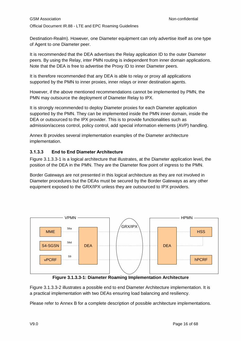
3.1.3.3 End to End Diameter Architecture
Figure 3.1.3.3-1 is a logical architecture that illustrates, at the Diameter application level, the
position of the DEA in the PMN. They are the Diameter flow point of ingress to the PMN.
Border Gateways are not presented in this logical architecture as they are not involved in
Diameter procedures but the DEAs must be secured by the Border Gateways as any other
equipment exposed to the GRX/IPX unless they are outsourced to IPX providers.
GRX/IPX
MME
S4-SGSN
vPCRF
HSS
hPCRF
DEADEA
S6a
S6d
S9
VPMN HPMN
Figure 3.1.3.3-1: Diameter Roaming Implementation Architecture
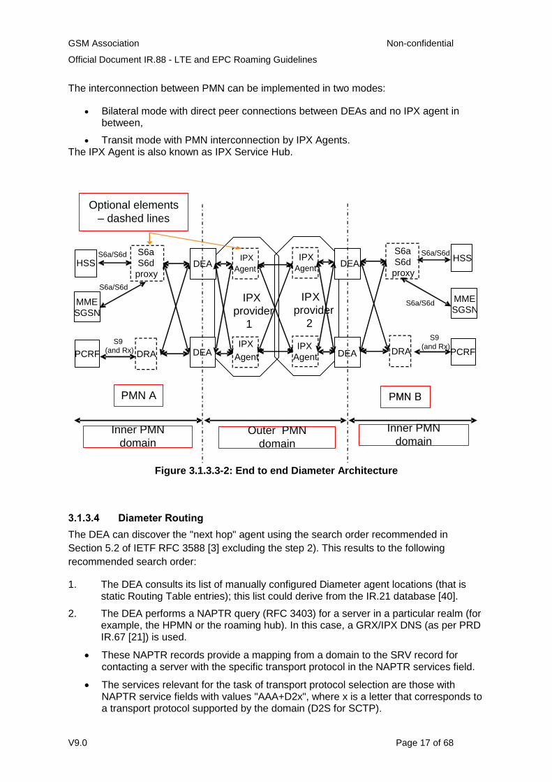
Figure 3.1.3.3-2 illustrates a possible end to end Diameter Architecture implementation. It is
a practical implementation with two DEAs ensuring load balancing and resiliency.
Please refer to Annex B for a complete description of possible architecture implementations.
GSM Association Non-confidential
Official Document IR.88 - LTE and EPC Roaming Guidelines
V9.0 Page 17 of 68
The interconnection between PMN can be implemented in two modes:
Bilateral mode with direct peer connections between DEAs and no IPX agent in between,
Transit mode with PMN interconnection by IPX Agents. The IPX Agent is also known as IPX Service Hub.
S9
(and Rx)
IPX
provider
1
DRA
DEA
DEA
MME
IPX
Agent
IPX
Agent
IPX
provider
2
IPX
Agent
IPX
Agent
DEA
DEA
S6a
S6d
proxy
DRA
HSS
PCRF
S6a/S6d
MME
SGSN S6a/S6d
S6a/S6d
S6a/S6d
S9
(and Rx)
S6a
S6d
proxy
Optional elements
– dashed lines
HSS
SGSN
PCRF
Inner PMN
domain Outer PMN
domain
Inner PMN
domain
PMN A PMN B
Figure 3.1.3.3-2: End to end Diameter Architecture
3.1.3.4 Diameter Routing
The DEA can discover the "next hop" agent using the search order recommended in
Section 5.2 of IETF RFC 3588 [3] excluding the step 2). This results to the following
recommended search order:
1. The DEA consults its list of manually configured Diameter agent locations (that is static Routing Table entries); this list could derive from the IR.21 database [40].
2. The DEA performs a NAPTR query (RFC 3403) for a server in a particular realm (for example, the HPMN or the roaming hub). In this case, a GRX/IPX DNS (as per PRD IR.67 [21]) is used.
These NAPTR records provide a mapping from a domain to the SRV record for contacting a server with the specific transport protocol in the NAPTR services field.
The services relevant for the task of transport protocol selection are those with NAPTR service fields with values "AAA+D2x", where x is a letter that corresponds to a transport protocol supported by the domain (D2S for SCTP).
GSM Association Non-confidential
Official Document IR.88 - LTE and EPC Roaming Guidelines
V9.0 Page 18 of 68
3. If no NAPTR records are found, the requester directly queries for SRV records: _diameter._sctp.<realm>. In this case, the GRX/IPX DNS (as per PRD IR.67IR.67 [21]) is used.
The use of NAPTR query (step 2 above) is recommended for DEA discovery (the
mechanism used by the outgoing DEA to determine the address on the far-end DEA) in the
case of direct bilateral roaming. The realm referred above means the Home Network Realm
of the Root Network Access Identifier (NAI) described in Section 19 of 3GPP TS 23.003 [7].
Diameter request routing and forwarding decision is always tied to specifically supported
applications unless Relay Agents are used. That means a DEA implemented as a Proxy
Agent and possible Proxy Agent based Hubs shall support those applications that are
required (such as S6a, S6d and/or S9) to enable inter-operator roaming. Support for new
applications must be added as they are required on the roaming interfaces.
The specific Relay Application ID 0xffffffff (in hexadecimal) as assigned by the IETF needs
to be advertised for a Diameter Relay Agent towards a VPMN.
Each of the three steps above has different security implications which are dealt with in
Section 6.5 and in Appendix C.
3.1.3.5 Diameter Transport Parameter
It is recommended that the default value defined in Section 12 of IETF RFC 3588 [3] is used
for Timer Tc, which is 30 sec. The Tc timer controls the frequency that transport connection
attempts are done to a peer with whom no active transport connection exists.
3.1.3.6 Notification of ME Identity
MME must obtain ME Identity (IMEISV) of the device as part of the E-UTRAN Initial Attach
procedure as specified in 3GPP TS23.401 [1]. The MME must then deliver the ME Identity
to HPLMN as Terminal-Information AVP in the Update Location Request message to HSS,
as specified in 3GPP TS29.272 [8]. If IMEI AVP is present in the Terminal-Information AVP,
then the Software-Version AVP must also be present.
If MME detects that the ME Identity is changed, the MME must notify HSS about an update
of the ME Identity using the Notification Procedure as specified in 3GPP TS29.272 [8]. If
IMEI AVP is present in the Terminal-Information AVP in the Notify Request message, then
the Software-Version AVP must also be present.
3.1.3.7 QoS for Diameter messages
Both HPMN and VPMN must procure the QoS using the DiffServ Code Point (DSCP).The
recommended DSCP values are defined in PRD IR.34 Section 6.1.2 [11].
GSM Association Non-confidential
Official Document IR.88 - LTE and EPC Roaming Guidelines
V9.0 Page 19 of 68
3.2 S8 Interface
3.2.1 Procedures
3.2.1.1 General
The Serving Gateway (SGW) and PDN (Packet Data Network) Gateway (PGW) selection
procedures specified for the EPS in 3GPP TS 29.303 [17] include relevant changes with
respect to the GGSN discovery procedures defined in previous releases of 3GPP:
The Release 8 behaviour includes the existing GPRS procedures plus additional functionality since the PGW (as opposed to the GGSN) now can support more than one protocol (GPRS Tunnelling Protocol (GTP) and now Proxy Mobile IP (PMIP)) and there is sometimes a desire to have the PGW and SGW collocated or topologically close to each other with respect to the network topology.
New DNS records are required to distinguish between different protocols and interfaces and assist in the more complicated selections.
Selection is performed using the S-NAPTR procedure ("Straightforward- Name Authority
Pointer (NAPTR)" procedure), which requires DNS NAPTR records to be provisioned as
described in IETF RFC 3958 [18].
IETF RFC 3958 [18] describes the Dynamic Delegation Discovery System (DDDS)
application procedures for resolving a domain name, application service name, and
application protocol to target server and port by using both NAPTR and SRV resource
records. It also describes how, following the DDDS standard, the NAPTR records are
looked up, and the rewrite rules (contained in the NAPTR records) are used to determine
the successive DNS lookups until a desirable target is found.
NOTE: The S-NAPTR use of the NAPTR resource record is exactly the same as defined in
IETF RFC 3403 [19] from the DNS server and DNS infrastructure point of view.
The PMN operator shall provision the authoritative DNS server responsible for the APN-
FQDN with NAPTR records for the given APN-FQDN and corresponding PGWs under the
APN-FQDN.
Assuming the SGW is in the visiting network and the APN to be selected is in the home
network then the S-NAPTR procedure shall use "Service Parameters" that select the
interface (S8 in this case) and the protocol (either GTP or PMIP).
In all cases, the S-NAPTR procedure returns an SRV record set (a set of FQDNs identifying
potential PGW and SGW candidates), or an A/AAAA record set (IP addresses identifying
potential PGW and SGW candidates), or a DNS error.
When provisioning NAPTR records in the DNS, NAPTR flags "a" for A/AAAA records or "s"
for SRV records should always be used. The use of NAPTR flag "" should be avoided. If
used, the precautions mentioned in Section 4.1.2 of 3GPP TS 29.303 [17] shall be taken
into consideration.
GSM Association Non-confidential
Official Document IR.88 - LTE and EPC Roaming Guidelines
V9.0 Page 20 of 68
3.2.1.2 SGW Selection
SGW selection is performed by the MME/SGSN at initial attach or PDN connection
establishment procedure. This occurs in the VPMN or the HPMN (non-roaming scenarios).
SGW selection is performed by using the S-NAPTR procedure with:
"Service Parameters" = {desired reference point, desired protocol}
"Application-Unique String" = the TAI FQDN (per 3GPP TS 23.003 [7])
For example, in a roaming scenario with Home routed traffic (S8) and assuming there is a
choice between PMIP and GTP protocols, the MME/SGSN performs SGW selection using
the S-NAPTR procedure with:
"Service Parameters" = {"x-3gpp-sgw:x-s8-gtp", "x-3gpp-sgw:x-s8-pmip"}
"Application-Unique String" = tac-lb<TAC-low-byte>.tac-hb<TAC-high-byte>.tac.epc.mnc<MNC>.mcc<MCC>.3gppnetwork.org
NOTE: Strictly speaking, SGW selection is outside the scope of this PRD, but is applicable
during the PGW/SGW collocated case.
3.2.1.3 PGW Selection
3.2.1.3.1 HPMN Roaming
PGW selection is performed by the MME/SGSN at initial attach or PDN connection
establishment.
PGW selection is performed by using the S-NAPTR procedure with:
"Service Parameters" = {desired reference point, desired protocol}
"Application-Unique String" = the APN FQDN (per 3GPP TS 23.003 [7])
For example, in a roaming scenario with Home routed traffic (S8) and assuming there is a
choice between PMIP and GTP protocols, the MME/SGSN performs PGW selection using
the S-NAPTR procedure with:
"Service Parameters" = {"x-3gpp-pgw:x-s8-gtp", "x-3gpp-pgw:x-s8-pmip"}
"Application-Unique String" = <APN-NI>.apn.epc.mnc<MNC>.mcc<MCC>.3gppnetwork.org
In addition, the VPMN SGSNs must support the Gateway selection procedure defined in TS
23.060 Annex A [29] including the UE-capability based gateway selection procedure (based
on which an SGSN can be configured to give priority towards SGW/PGW for LTE capable
UEs as defined in TS 23.060, Section 5.3.7.1 [29]).
This is required to ensure service continuity for a LTE roamer when moving from
GERAN/UTRAN coverage to LTE one in some of the coexistence scenarios described in
chapter 4.2.
GSM Association Non-confidential
Official Document IR.88 - LTE and EPC Roaming Guidelines
V9.0 Page 21 of 68
3.2.1.3.2 VPMN Roaming
The details of selecting a PGW in VPMN are same as for HPMN Roaming, which is
described in the previous section. Section 3.2.1.4 of this document describes further details
of local PGW selection for LTE Voice Roaming architecture.
3.2.1.4 Combined SGW/PGW Selection
For locally routed traffic (local break-out in the VPMN) then PGW/SGW collocation is
possible. In this case the MME/SGSN compares the two record sets (one for PGW and one
for SGW candidates) and looks for a match of the canonical-node name (which conveys a
collocated SGW/PGW):
If there are multiple PGW/SGW collocated nodes in the two (2) record-sets, weights and priorities are used to select the optimal collocated PGW/SGW that serves the user's cell.
If there is a failure to contact the collocated node, the non-collocated nodes are used.
3.2.2 GTP
The S8 interface (GTP based) uses GTP version 1 for the User plane, and GTP version 2
for the Control plane. Nodes supporting the S8-GTP based interface are compliant to 3GPP
TS 29.274 [4] Release 8 or later, and 3GPP TS 29.281 [5] Release 8 or later. Accordingly
fallback to GTP version 0 is no longer supported; this has significance if hybrid networks
containing legacy nodes are sharing infrastructure.
3.2.3 PMIP
Nodes supporting the S8-PMIP based interface are compliant to 3GPP TS 23.402 [2] and
3GPP TS 29.275 [23] Release 8 or later.
3.2.4 PMIP-GTP Interworking
The PMIP-GTP interworking is not supported by 3GPP specifications. The PMN supporting
PMIP must deploy GTP based S8 or Gp interface in order to interwork with GTP-S8/Gp
based PMN, unless the GTP-S8 based PMN also deploys PMIP based S8.
3.3 S9 Interface
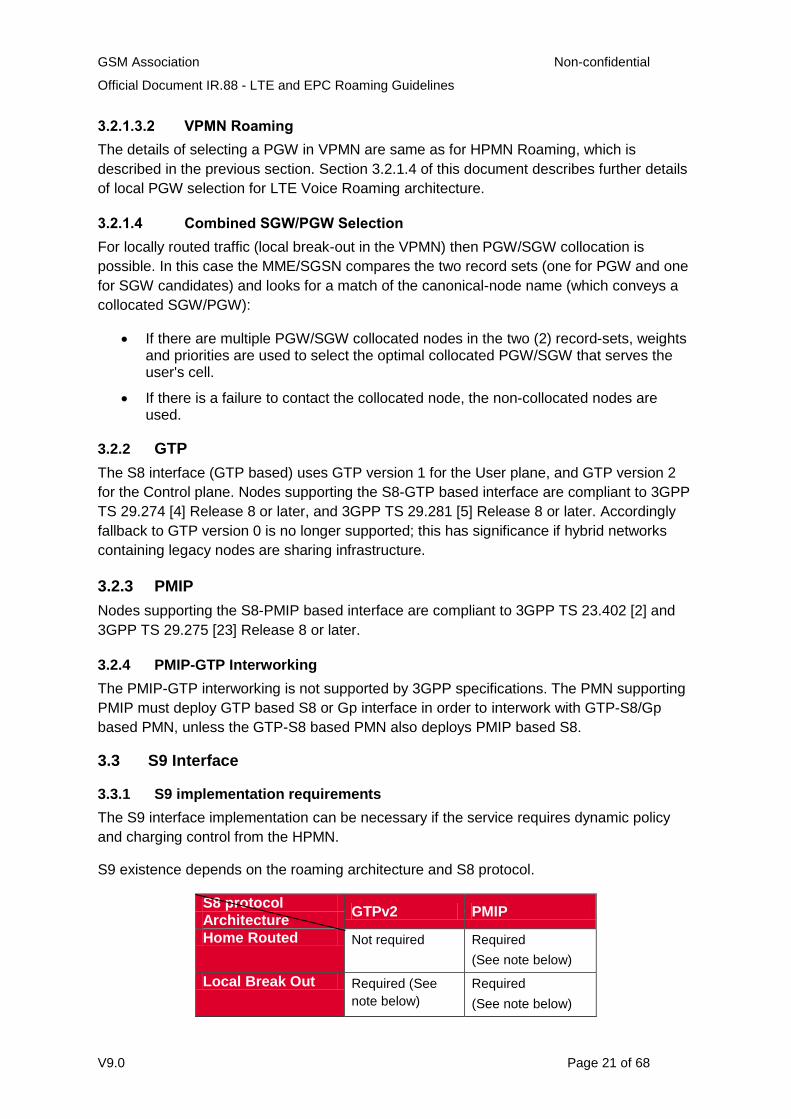
3.3.1 S9 implementation requirements
The S9 interface implementation can be necessary if the service requires dynamic policy
and charging control from the HPMN.
S9 existence depends on the roaming architecture and S8 protocol.
S8 protocol GTPv2 PMIP
Architecture
Home Routed Not required Required
(See note below)
Local Break Out Required (See
note below)
Required
(See note below)
GSM Association Non-confidential
Official Document IR.88 - LTE and EPC Roaming Guidelines
V9.0 Page 22 of 68
NOTE: Only if dynamic policy and charging control with home network control is required.
Table 3.3.1-1: S9 interface implementation
3.3.2 Guidelines for Diameter interface over S9 interface
The S9 interface between PCRFs implements Diameter. Parameters and guidelines for the
Diameter protocol will be same as those of S6a (see Sections 3.1.3 and 3.4).
3.4 S6a and S6d interface
For S6a and S6d interfaces, the guidelines described in Section 3.1.3 apply.
If both HPMN and VPMN have S6d capability, S6d can be used. The use of S6d must be
agreed between two PMNs as part of their bilateral roaming agreement.
If aforementioned condition is not met, then the interface between HSS and SGSN is Gr
(GSM-MAP). If HPMN have Diameter-only HSS or if VPMN have S6d-only SGSN, a
Diameter-MAP IWF must be implemented in between HPMN and VPMN. The responsibility
of the IWF implementation belongs to the PMN that does not support the MAP Gr interface.
The IWF can be outsourced to IPX, but this must be done by the responsible PMN.
4 Technical Requirements and Recommendations for Legacy Interworking and Coexistence
4.1 Legacy Interworking scenarios
4.1.1 Introduction
It is anticipated that most commercial LTE-device roaming configurations will use Release 8
(or later) capabilities at the Home and Visited networks (in HSS, SGW, PDN Gateway, and
if applicable PCRFs).
There are two options for the support of authentication, registration and subscription
download when roaming to Release 8 SGSNs. This scenario will typically occur when both
networks support LTE. The two options are to either continue using MAP based Gr
interface, or to use the Diameter based S6d interface.
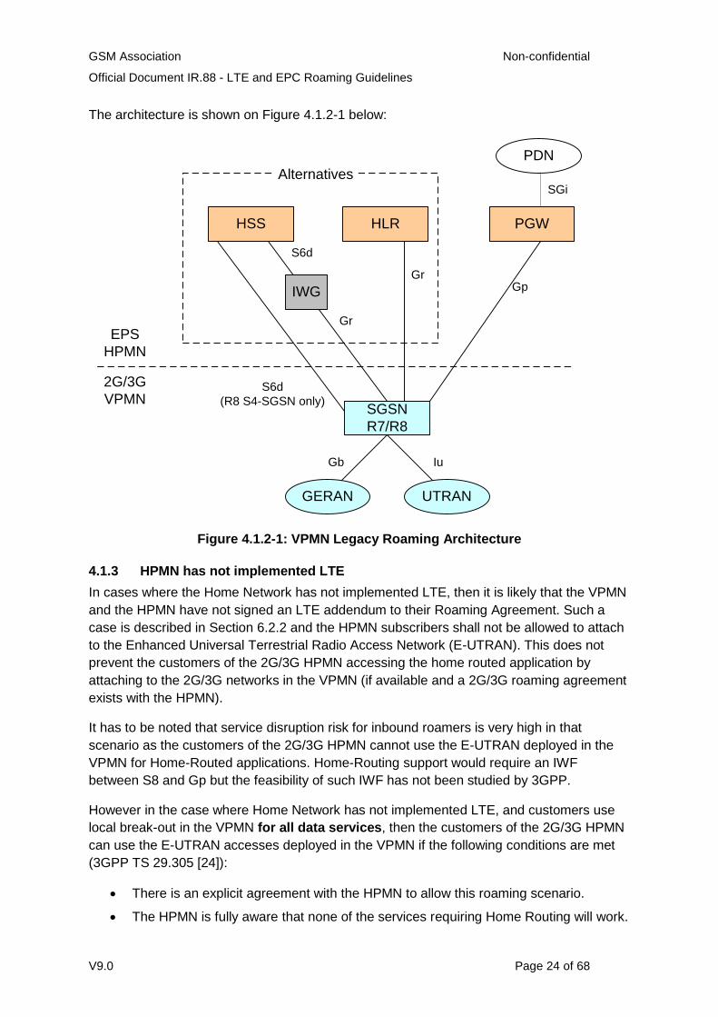
4.1.2 VPMN has not implemented LTE
In cases where the Visited Network has not implemented LTE, then the roaming takes place
in accordance with GPRS/HSPA recommendations. In particular:
It is assumed that the MAP-Diameter IWF function is performed by the EPS operator.
The PDN Gateway in HPMN implements the Gp interface towards the SGSN in VPMN.
The HPMN implements the Gr interface or supports Gr functionality via an IWF to enable the authentication of its customers in the VPMN.
From the 2G/3G VPMN, the EPS HPMN "looks like" a GPRS network.

GSM Association Non-confidential
Official Document IR.88 - LTE and EPC Roaming Guidelines
V9.0 Page 23 of 68
No changes to the existing GTPv1 and MAP roaming interfaces at the VPMN are required.
GSM Association Non-confidential
Official Document IR.88 - LTE and EPC Roaming Guidelines
V9.0 Page 24 of 68
The architecture is shown on Figure 4.1.2-1 below:
PGWHLRHSS
PDN
SGi
SGSN
R7/R8
GERAN UTRAN
2G/3G
VPMN
EPS
HPMN
IWG GpGr
Gr
S6d
S6d
(R8 S4-SGSN only)
Gb Iu
Alternatives
Figure 4.1.2-1: VPMN Legacy Roaming Architecture
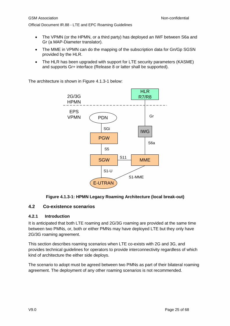
4.1.3 HPMN has not implemented LTE
In cases where the Home Network has not implemented LTE, then it is likely that the VPMN
and the HPMN have not signed an LTE addendum to their Roaming Agreement. Such a
case is described in Section 6.2.2 and the HPMN subscribers shall not be allowed to attach
to the Enhanced Universal Terrestrial Radio Access Network (E-UTRAN). This does not
prevent the customers of the 2G/3G HPMN accessing the home routed application by
attaching to the 2G/3G networks in the VPMN (if available and a 2G/3G roaming agreement
exists with the HPMN).
It has to be noted that service disruption risk for inbound roamers is very high in that
scenario as the customers of the 2G/3G HPMN cannot use the E-UTRAN deployed in the
VPMN for Home-Routed applications. Home-Routing support would require an IWF
between S8 and Gp but the feasibility of such IWF has not been studied by 3GPP.
However in the case where Home Network has not implemented LTE, and customers use
local break-out in the VPMN for all data services, then the customers of the 2G/3G HPMN
can use the E-UTRAN accesses deployed in the VPMN if the following conditions are met
(3GPP TS 29.305 [24]):
There is an explicit agreement with the HPMN to allow this roaming scenario.
The HPMN is fully aware that none of the services requiring Home Routing will work.
GSM Association Non-confidential
Official Document IR.88 - LTE and EPC Roaming Guidelines
V9.0 Page 25 of 68
The VPMN (or the HPMN, or a third party) has deployed an IWF between S6a and Gr (a MAP-Diameter translator).
The MME in VPMN can do the mapping of the subscription data for Gn/Gp SGSN provided by the HLR.
The HLR has been upgraded with support for LTE security parameters (KASME) and supports Gr+ interface (Release 8 or latter shall be supported).
The architecture is shown in Figure 4.1.3-1 below:
MME
E-UTRAN
EPS
VPMN
2G/3G
HPMN
S1-MME
SGW
PGW
PDN
SGi
S5
S1-U
S11
HLR
R7/R8
IWG
S6a
Gr
Figure 4.1.3-1: HPMN Legacy Roaming Architecture (local break-out)
4.2 Co-existence scenarios
4.2.1 Introduction
It is anticipated that both LTE roaming and 2G/3G roaming are provided at the same time
between two PMNs, or, both or either PMNs may have deployed LTE but they only have
2G/3G roaming agreement.
This section describes roaming scenarios when LTE co-exists with 2G and 3G, and
provides technical guidelines for operators to provide interconnectivity regardless of which
kind of architecture the either side deploys.
The scenario to adopt must be agreed between two PMNs as part of their bilateral roaming
agreement. The deployment of any other roaming scenarios is not recommended.
GSM Association Non-confidential
Official Document IR.88 - LTE and EPC Roaming Guidelines
V9.0 Page 26 of 68
4.2.2 Possible scenarios
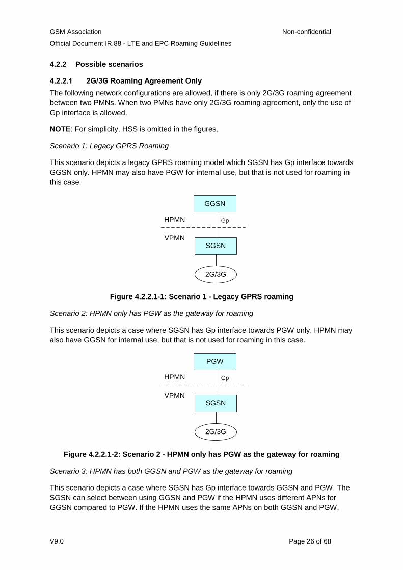
4.2.2.1 2G/3G Roaming Agreement Only
The following network configurations are allowed, if there is only 2G/3G roaming agreement
between two PMNs. When two PMNs have only 2G/3G roaming agreement, only the use of
Gp interface is allowed.
NOTE: For simplicity, HSS is omitted in the figures.
Scenario 1: Legacy GPRS Roaming
This scenario depicts a legacy GPRS roaming model which SGSN has Gp interface towards
GGSN only. HPMN may also have PGW for internal use, but that is not used for roaming in
this case.
VPMN
HPMN
GGSN
SGSN
Gp
2G/3G
Figure 4.2.2.1-1: Scenario 1 - Legacy GPRS roaming
Scenario 2: HPMN only has PGW as the gateway for roaming
This scenario depicts a case where SGSN has Gp interface towards PGW only. HPMN may
also have GGSN for internal use, but that is not used for roaming in this case.
VPMN
HPMN
PGW
SGSN
Gp
2G/3G
Figure 4.2.2.1-2: Scenario 2 - HPMN only has PGW as the gateway for roaming
Scenario 3: HPMN has both GGSN and PGW as the gateway for roaming
This scenario depicts a case where SGSN has Gp interface towards GGSN and PGW. The
SGSN can select between using GGSN and PGW if the HPMN uses different APNs for
GGSN compared to PGW. If the HPMN uses the same APNs on both GGSN and PGW,
GSM Association Non-confidential
Official Document IR.88 - LTE and EPC Roaming Guidelines
V9.0 Page 27 of 68
then VPMN SGSN must use UE-capability as follows: If UE is LTE capable, then PGW must
be selected, and if the UE is only 2G/3G capable, GGSN must be selected.
VPMN
HPMN
GGSN
SGSN
Gp
2G/3G
PGW
Gp
Figure 4.2.2.1-3: Scenario 3 - HPMN has both GGSN and PGW as the gateway for
roaming
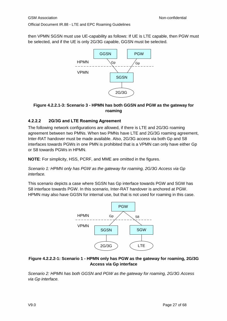
4.2.2.2 2G/3G and LTE Roaming Agreement
The following network configurations are allowed, if there is LTE and 2G/3G roaming
agreement between two PMNs. When two PMNs have LTE and 2G/3G roaming agreement,
Inter-RAT handover must be made available. Also, 2G/3G access via both Gp and S8
interfaces towards PGWs in one PMN is prohibited that is a VPMN can only have either Gp
or S8 towards PGWs in HPMN.
NOTE: For simplicity, HSS, PCRF, and MME are omitted in the figures.
Scenario 1: HPMN only has PGW as the gateway for roaming, 2G/3G Access via Gp
interface.
This scenario depicts a case where SGSN has Gp interface towards PGW and SGW has
S8 interface towards PGW. In this scenario, Inter-RAT handover is anchored at PGW.
HPMN may also have GGSN for internal use, but that is not used for roaming in this case.
VPMN
HPMN
PGW
SGSN
Gp
2G/3G
SGW
LTE
S8
Figure 4.2.2.2-1: Scenario 1 - HPMN only has PGW as the gateway for roaming, 2G/3G
Access via Gp interface
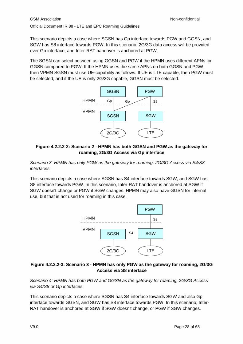
Scenario 2: HPMN has both GGSN and PGW as the gateway for roaming, 2G/3G Access
via Gp interface.
GSM Association Non-confidential
Official Document IR.88 - LTE and EPC Roaming Guidelines
V9.0 Page 28 of 68
This scenario depicts a case where SGSN has Gp interface towards PGW and GGSN, and
SGW has S8 interface towards PGW. In this scenario, 2G/3G data access will be provided
over Gp interface, and Inter-RAT handover is anchored at PGW.
The SGSN can select between using GGSN and PGW if the HPMN uses different APNs for
GGSN compared to PGW. If the HPMN uses the same APNs on both GGSN and PGW,
then VPMN SGSN must use UE-capability as follows: If UE is LTE capable, then PGW must
be selected, and if the UE is only 2G/3G capable, GGSN must be selected.
VPMN
HPMN
PGW
2G/3G LTE
GGSN
SGSN SGW
Gp Gp S8
Figure 4.2.2.2-2: Scenario 2 - HPMN has both GGSN and PGW as the gateway for
roaming, 2G/3G Access via Gp interface
Scenario 3: HPMN has only PGW as the gateway for roaming, 2G/3G Access via S4/S8
interfaces.
This scenario depicts a case where SGSN has S4 interface towards SGW, and SGW has
S8 interface towards PGW. In this scenario, Inter-RAT handover is anchored at SGW if
SGW doesn't change or PGW if SGW changes. HPMN may also have GGSN for internal
use, but that is not used for roaming in this case.
VPMN
HPMN
PGW
2G/3G LTE
SGSN SGW
S8
S4
Figure 4.2.2.2-3: Scenario 3 - HPMN has only PGW as the gateway for roaming, 2G/3G
Access via S8 interface
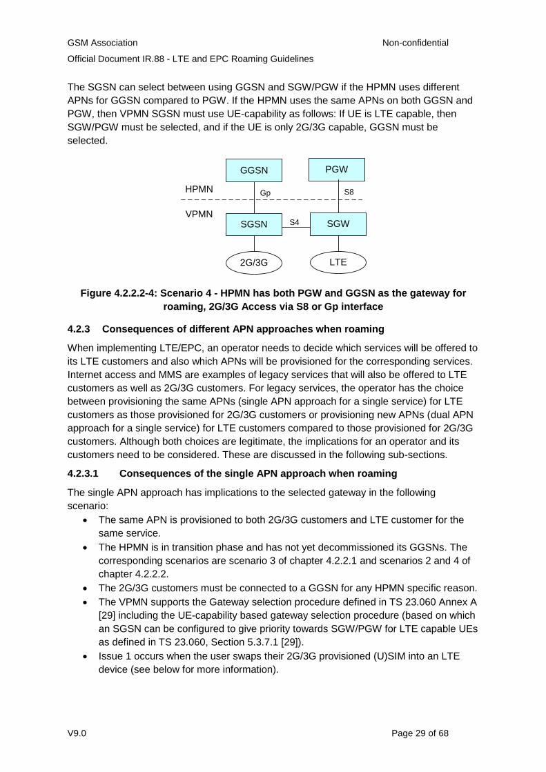
Scenario 4: HPMN has both PGW and GGSN as the gateway for roaming, 2G/3G Access
via S4/S8 or Gp interfaces.
This scenario depicts a case where SGSN has S4 interface towards SGW and also Gp
interface towards GGSN, and SGW has S8 interface towards PGW. In this scenario, Inter-
RAT handover is anchored at SGW if SGW doesn't change, or PGW if SGW changes.
GSM Association Non-confidential
Official Document IR.88 - LTE and EPC Roaming Guidelines
V9.0 Page 29 of 68
The SGSN can select between using GGSN and SGW/PGW if the HPMN uses different
APNs for GGSN compared to PGW. If the HPMN uses the same APNs on both GGSN and
PGW, then VPMN SGSN must use UE-capability as follows: If UE is LTE capable, then
SGW/PGW must be selected, and if the UE is only 2G/3G capable, GGSN must be
selected.
VPMN
HPMN
PGW
2G/3G LTE
SGSN SGW
S8
S4
GGSN
Gp
Figure 4.2.2.2-4: Scenario 4 - HPMN has both PGW and GGSN as the gateway for
roaming, 2G/3G Access via S8 or Gp interface
4.2.3 Consequences of different APN approaches when roaming
When implementing LTE/EPC, an operator needs to decide which services will be offered to
its LTE customers and also which APNs will be provisioned for the corresponding services.
Internet access and MMS are examples of legacy services that will also be offered to LTE
customers as well as 2G/3G customers. For legacy services, the operator has the choice
between provisioning the same APNs (single APN approach for a single service) for LTE
customers as those provisioned for 2G/3G customers or provisioning new APNs (dual APN
approach for a single service) for LTE customers compared to those provisioned for 2G/3G
customers. Although both choices are legitimate, the implications for an operator and its
customers need to be considered. These are discussed in the following sub-sections.
4.2.3.1 Consequences of the single APN approach when roaming
The single APN approach has implications to the selected gateway in the following
scenario:
The same APN is provisioned to both 2G/3G customers and LTE customer for the
same service.
The HPMN is in transition phase and has not yet decommissioned its GGSNs. The
corresponding scenarios are scenario 3 of chapter 4.2.2.1 and scenarios 2 and 4 of
chapter 4.2.2.2.
The 2G/3G customers must be connected to a GGSN for any HPMN specific reason.
The VPMN supports the Gateway selection procedure defined in TS 23.060 Annex A
[29] including the UE-capability based gateway selection procedure (based on which
an SGSN can be configured to give priority towards SGW/PGW for LTE capable UEs
as defined in TS 23.060, Section 5.3.7.1 [29]).
Issue 1 occurs when the user swaps their 2G/3G provisioned (U)SIM into an LTE
device (see below for more information).
GSM Association Non-confidential
Official Document IR.88 - LTE and EPC Roaming Guidelines
V9.0 Page 30 of 68
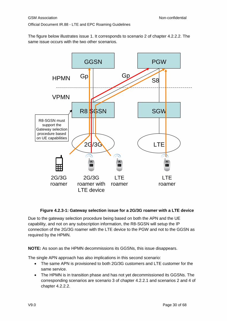
The figure below illustrates issue 1. It corresponds to scenario 2 of chapter 4.2.2.2. The
same issue occurs with the two other scenarios.
Figure 4.2.3-1: Gateway selection issue for a 2G/3G roamer with a LTE device
Due to the gateway selection procedure being based on both the APN and the UE
capability, and not on any subscription information, the R8-SGSN will setup the IP
connection of the 2G/3G roamer with the LTE device to the PGW and not to the GGSN as
required by the HPMN.
NOTE: As soon as the HPMN decommissions its GGSNs, this issue disappears.
The single APN approach has also implications in this second scenario:
The same APN is provisioned to both 2G/3G customers and LTE customer for the
same service.
The HPMN is in transition phase and has not yet decommissioned its GGSNs. The
corresponding scenarios are scenario 3 of chapter 4.2.2.1 and scenarios 2 and 4 of
chapter 4.2.2.2.
PGW
R8 SGSN SGW
GGSN
Gp Gp S8 HPMN
VPMN
2G/3G LTE
LTE roamer
LTE roamer
2G/3G roamer
2G/3G roamer with LTE device
R8-SGSN must support the
Gateway selection procedure based on UE capabilities

GSM Association Non-confidential
Official Document IR.88 - LTE and EPC Roaming Guidelines
V9.0 Page 31 of 68
The 2G/3G customers must be connected to a GGSN for any HPMN specific reason.
The VPMN DOES NOT support the UE-capability based gateway selection
procedure.
Issue 2 occurs when the LTE roamer moves from the GERAN/UTRAN coverage to
the LTE one.
In order to guarantee service continuity for subscribers moving between GERAN/UTRAN
and LTE coverage it is required to anchor a packet session for LTE capable UEs at a PGW
and not at a legacy GGSN.
Figure 4.2.3-1: Service continuity issue for a LTE roamer
The PDP session setup under foreign GERAN/UTRAN will succeed if the SGSN does not
support the UE-capability based gateway selection procedure. But if the subscriber is
reaching LTE coverage in the VPLMN and the UE is initiating an inter RAT change from
GERAN/UTRAN to LTE the packet session will drop because the anchor will change (see
above figure).
NOTE: As soon as the VPMN upgrades its SGSNs to support the UE-capability based
gateway selection procedure or the HPMN decommissions its GGSNs, this issue
disappears.
4.2.3.2 Consequences of the dual APN approach when roaming
If an operator decides to use dual APNs for its customers (where legacy APNs are
provisioned for 2G/3G customers only and different APNs are provisioned for LTE
customers), the following must be noted:
Different APNs are provisioned for different customers (2G/3G and LTE customers)
for the same service therefore requiring additional testing.
GSM Association Non-confidential
Official Document IR.88 - LTE and EPC Roaming Guidelines
V9.0 Page 32 of 68
2G/3G roamers with legacy devices will continue to be anchored on the GGSN
based on DNS queries by the SGSN.
LTE roamers will be anchored on the PGW.
A 2G/3G roamer using an LTE device (SIM swap scenario) will be anchored on the
GGSN.
An LTE roamer camping on UTRAN/GERAN will be anchored on the PGW. This
ensures session continuity when the LTE roamer moves to LTE coverage.
4.2.3.3 Guidance regarding the APN approach when roaming
Based on the considerations in sections 4.2.3.1 and 4.2.3.2, the HPMN operator should take into account when choosing the APN approach when roaming:
If the HPMN has decommissioned its GGSNs, the single APN approach has no issues.
If the HPMN is in transition phase and has not yet decommissioned its GGSNs, the dual
APN approach has no issues.
4.3 Inter-RAT Handover
4.3.1 Handover to/from 2G/3G and LTE
4.3.1.1 Introduction
Requirements on handover to/from 2G/3G and LTE are partly captured in Section 4.2. The
following sections outline requirements for the Inter-RAT handover.
4.3.1.2 Handover restriction to/from 2G/3G and LTE (Active mode)
As illustrated in Figure 4.3.1-1, an LTE capable UE in 2G/3G access can be frequently
handed over to LTE and any active data connectivity can be severely disrupted under the
condition that a roaming agreement exists for 2G/3G but not for LTE between the PMNs.
A similar problem can happen also when:
1. A UE in LTE access is handed over to 2G/3G under the condition that a roaming
agreement exists for LTE but not for 2G/3G between the pmns; or
2. The subscriber does not have the subscription to use the specific access type (for
example, LTE), even when a roaming agreement exists for both LTE and 2G/3G
between the pmns.
NOTE 1: Item 1 described above is considered a migratory problem while operators update
their existing roaming agreements to encompass all the radio accesses.
GSM Association Non-confidential
Official Document IR.88 - LTE and EPC Roaming Guidelines
V9.0 Page 33 of 68
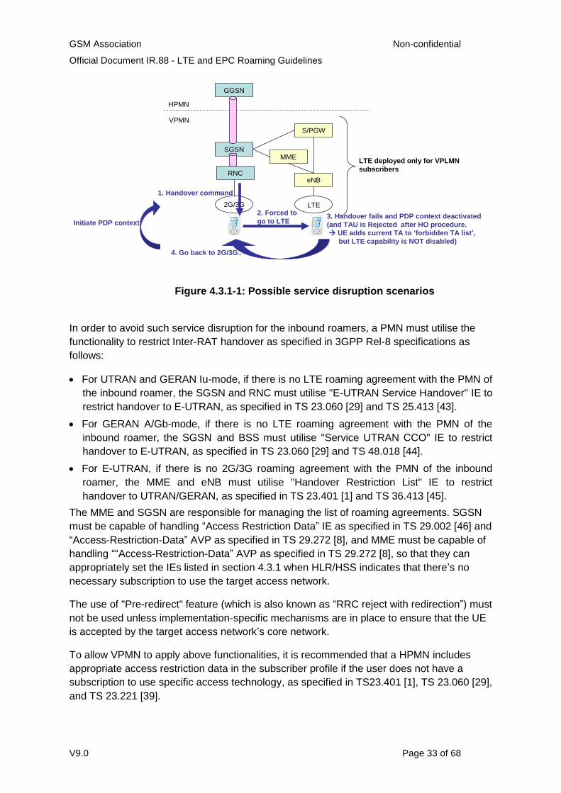
Figure 4.3.1-1: Possible service disruption scenarios
In order to avoid such service disruption for the inbound roamers, a PMN must utilise the
functionality to restrict Inter-RAT handover as specified in 3GPP Rel-8 specifications as
follows:
For UTRAN and GERAN Iu-mode, if there is no LTE roaming agreement with the PMN of
the inbound roamer, the SGSN and RNC must utilise "E-UTRAN Service Handover" IE to
restrict handover to E-UTRAN, as specified in TS 23.060 [29] and TS 25.413 [43].
For GERAN A/Gb-mode, if there is no LTE roaming agreement with the PMN of the
inbound roamer, the SGSN and BSS must utilise "Service UTRAN CCO" IE to restrict
handover to E-UTRAN, as specified in TS 23.060 [29] and TS 48.018 [44].
For E-UTRAN, if there is no 2G/3G roaming agreement with the PMN of the inbound
roamer, the MME and eNB must utilise "Handover Restriction List" IE to restrict
handover to UTRAN/GERAN, as specified in TS 23.401 [1] and TS 36.413 [45].
The MME and SGSN are responsible for managing the list of roaming agreements. SGSN
must be capable of handling “Access Restriction Data” IE as specified in TS 29.002 [46] and
“Access-Restriction-Data” AVP as specified in TS 29.272 [8], and MME must be capable of
handling ““Access-Restriction-Data” AVP as specified in TS 29.272 [8], so that they can
appropriately set the IEs listed in section 4.3.1 when HLR/HSS indicates that there’s no
necessary subscription to use the target access network.
The use of "Pre-redirect" feature (which is also known as “RRC reject with redirection”) must
not be used unless implementation-specific mechanisms are in place to ensure that the UE
is accepted by the target access network’s core network.
To allow VPMN to apply above functionalities, it is recommended that a HPMN includes
appropriate access restriction data in the subscriber profile if the user does not have a
subscription to use specific access technology, as specified in TS23.401 [1], TS 23.060 [29],
and TS 23.221 [39].
SGSN
GGSN
HPMN
VPMN
2G/3G
RNC
S/PGW
MME
eNB
LTE
LTE deployed only for VPLMN
subscribers
1. Handover command
2. Forced to
go to LTE3. Handover fails and PDP context deactivated
(and TAU is Rejected after HO procedure.
UE adds current TA to ‘forbidden TA list’,
but LTE capability is NOT disabled)
4. Go back to 2G/3G..
Initiate PDP context
GSM Association Non-confidential
Official Document IR.88 - LTE and EPC Roaming Guidelines
V9.0 Page 34 of 68
4.3.1.3 Handover restriction to/from 2G/3G and LTE (Idle mode)
If a roaming agreement exists for 2G/3G but not for LTE between the PMNs, then the
following problematic scenario may exist:
1. UE with LTE capability in idle-mode camping on 2G/3G reselects E-UTRAN.
2. The UE sends a TAU Request message through eNodeB to MME.
3. The MME finds that the authentication procedure fails and returns a TAU Reject
message with the cause value #15.
4. The UE adds the TA to the forbidden TA list and switches to 2G/3G.
5. The steps (1) and (2) occur.
6. The UE reads broadcasted system information, finds that the TA is in the forbidden
TA list, and switches back to 2G/3G.
7. The procedure repeats itself when the TA is removed from the forbidden TA list after
implementation specific value between 12h - 24h (as specified in TS24.301 [32]).
The above problematic scenario causes unnecessary signalling traffic for RNC, SGSN,
eNodeB, MME, and S-GW of VPMN.
A similar problem can happen also when a UE in idle-mode on LTE access moves to 2G/3G
under the condition that a roaming agreement exists for LTE but not for 2G/3G between the
PMNs.
The MME and SGSN are responsible for managing the list of roaming agreements. The
MME and SGSN must provide “Radio Access Technology / Frequency Selection Priority
(RFSP) index” to eNB/RNC as specified in TS23.401 [1] and TS23.060 [29]. Based on the
RFSP index provided, the RNC provides camping policy to the UE to not camp on either
LTE/2G/3G using RRC signalling. The UE then does not camp on the radio access which
the UE does not have subscription to access.
To allow VPMN to apply above functionalities, it is recommended that a HPMN includes
appropriate access restriction data in the subscriber profile if the user does not have a
subscription to use specific access technology, as specified in TS23.401 [1], TS 23.060 [29],
and TS 23.221 [39].
4.3.2 Handover to/from non-3GPP accesses and LTE
Roaming from/to non-3GPP access is not supported in this version of the document.
Accordingly, the handover to/from non-3GPP accesses and LTE is not supported in this
version of the document.
5 Technical Requirements and Recommendations for Services
5.1 Short Message Service (SMS)
5.1.1 SMS over SGs
SMS over SGs is a means to provide C-Plane based SMS over LTE access without forcing
UE to fall back to overlay 2G/3G accesses. SMS over SGs is defined in 3GPP TS 23.272
[25].
GSM Association Non-confidential
Official Document IR.88 - LTE and EPC Roaming Guidelines
V9.0 Page 35 of 68
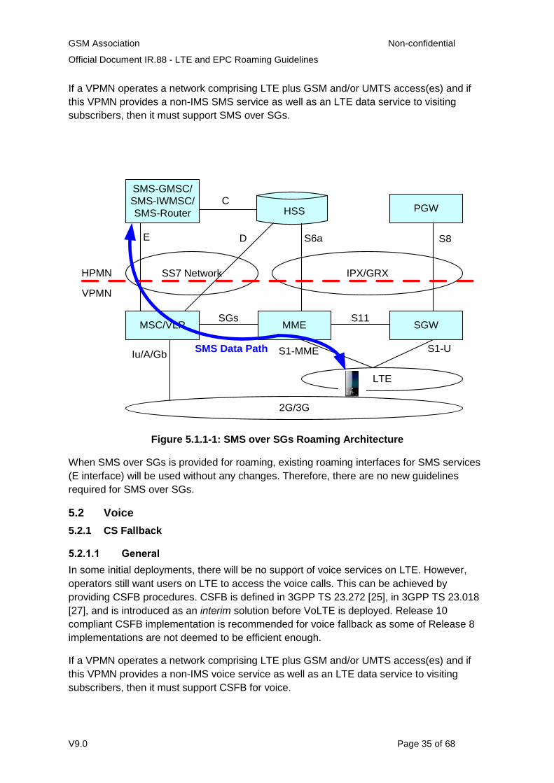
If a VPMN operates a network comprising LTE plus GSM and/or UMTS access(es) and if
this VPMN provides a non-IMS SMS service as well as an LTE data service to visiting
subscribers, then it must support SMS over SGs.
HSS PGW
SGWMMEMSC/VLR
SMS-GMSC/
SMS-IWMSC/
SMS-Router
SS7 Network IPX/GRX
E D
LTE
2G/3G
S6a S8
S11SGs
S1-MME S1-UIu/A/Gb
HPMN
VPMN
SMS Data Path
C
Figure 5.1.1-1: SMS over SGs Roaming Architecture
When SMS over SGs is provided for roaming, existing roaming interfaces for SMS services
(E interface) will be used without any changes. Therefore, there are no new guidelines
required for SMS over SGs.
5.2 Voice
5.2.1 CS Fallback
5.2.1.1 General
In some initial deployments, there will be no support of voice services on LTE. However,
operators still want users on LTE to access the voice calls. This can be achieved by
providing CSFB procedures. CSFB is defined in 3GPP TS 23.272 [25], in 3GPP TS 23.018
[27], and is introduced as an interim solution before VoLTE is deployed. Release 10
compliant CSFB implementation is recommended for voice fallback as some of Release 8
implementations are not deemed to be efficient enough.
If a VPMN operates a network comprising LTE plus GSM and/or UMTS access(es) and if
this VPMN provides a non-IMS voice service as well as an LTE data service to visiting
subscribers, then it must support CSFB for voice.
GSM Association Non-confidential
Official Document IR.88 - LTE and EPC Roaming Guidelines
V9.0 Page 36 of 68
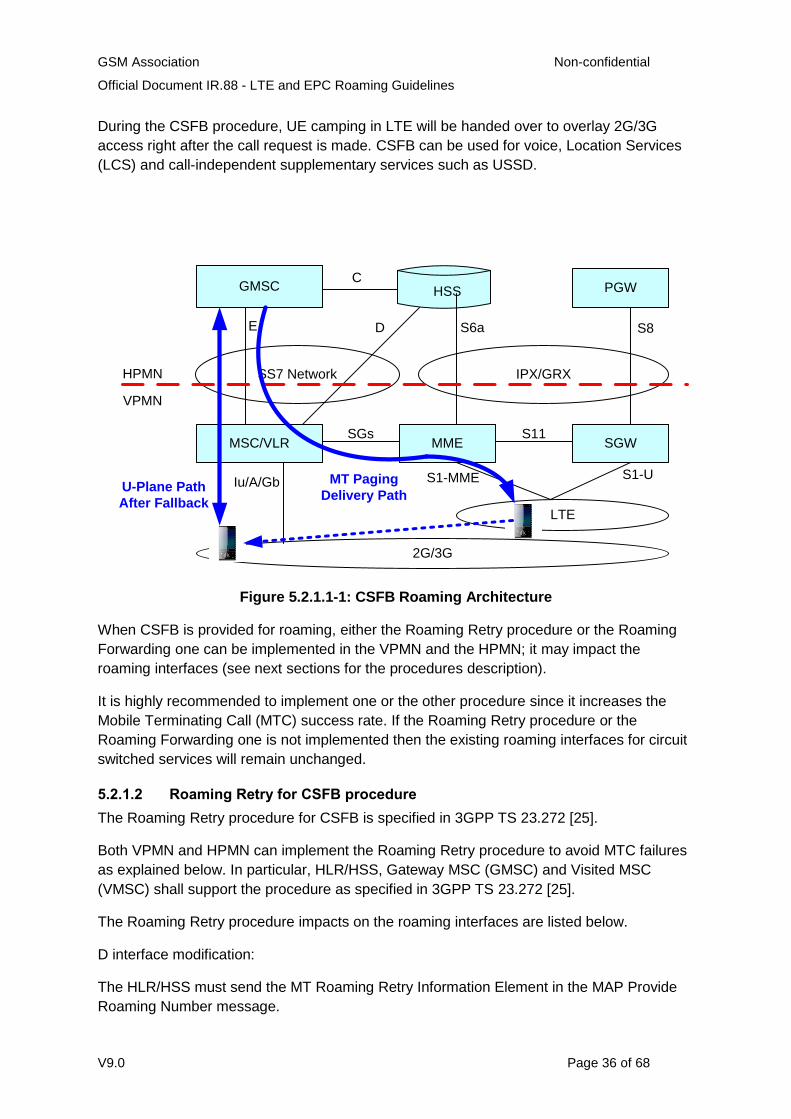
During the CSFB procedure, UE camping in LTE will be handed over to overlay 2G/3G
access right after the call request is made. CSFB can be used for voice, Location Services
(LCS) and call-independent supplementary services such as USSD.
HSS PGW
SGWMMEMSC/VLR
GMSC
SS7 Network IPX/GRX
E D
LTE
2G/3G
S6a S8
S11SGs
S1-MME S1-UIu/A/Gb
HPMN
VPMN
MT Paging
Delivery Path
C
U-Plane Path
After Fallback
Figure 5.2.1.1-1: CSFB Roaming Architecture
When CSFB is provided for roaming, either the Roaming Retry procedure or the Roaming
Forwarding one can be implemented in the VPMN and the HPMN; it may impact the
roaming interfaces (see next sections for the procedures description).
It is highly recommended to implement one or the other procedure since it increases the
Mobile Terminating Call (MTC) success rate. If the Roaming Retry procedure or the
Roaming Forwarding one is not implemented then the existing roaming interfaces for circuit
switched services will remain unchanged.
5.2.1.2 Roaming Retry for CSFB procedure
The Roaming Retry procedure for CSFB is specified in 3GPP TS 23.272 [25].
Both VPMN and HPMN can implement the Roaming Retry procedure to avoid MTC failures
as explained below. In particular, HLR/HSS, Gateway MSC (GMSC) and Visited MSC
(VMSC) shall support the procedure as specified in 3GPP TS 23.272 [25].
The Roaming Retry procedure impacts on the roaming interfaces are listed below.
D interface modification:
The HLR/HSS must send the MT Roaming Retry Information Element in the MAP Provide
Roaming Number message.
GSM Association Non-confidential
Official Document IR.88 - LTE and EPC Roaming Guidelines
V9.0 Page 37 of 68
E Interface implementation:
The E interface between the VPMN and HPMN must be implemented. The GMSC and
VMSC must support the Resume Call Handling MAP procedure.
The entire concept of CSFB relies on a careful and combined radio engineering of the
Location Areas and Tracking Areas at the MSC (pool) area boundaries. More precisely, the
Tracking Areas (TA) Lists at MSC pool area boundaries must be configured such that they
do not extend beyond the coverage of the corresponding Location Areas (LA).
The following figure illustrates a LA-TA misalignment on the MSC coverage boundaries.
MSC#1 MME#1 MSC#2 MME#2
RNC#1 RNC#2
LA1 LA2LA3
TA1 TA2 TA3
Paging
CSFB
Page
Response
SGs#1 SGs#2
MSC Pool Area#2MSC Pool Area#1
2G/3G
LTE
Figure 5.2.1.2-1: CSFB issue due to TA/LA misalignment
When the TA List coverage extends beyond the LA one then there will be some cases
where the UE will actually fall-back on a 2G/3G cell belonging to another MSC than the one
where it registered during the combined EPS/IMSI Attach or the combined Tracking Area
Update/Location Area Update. For instance, Figure 5.2.1.2-1 depicts the case where the UE
which is registered under TA2/LA2 of MSC1 receives a paging for an MTC. Depending on
the geographical position of the UE when it falls back to 2G/3G, it may select a cell in LA3 of
MSC2. In such situation, the UE will send the paging response to MSC2, which is not aware
of the call establishment and does not have the subscriber’s profile. So without Roaming
Retry procedure, such MTC would fail.
Roaming Retry allows releasing the call leg established between the HPMN GMSC and
MSC1 and re-establishing it from GMSC to MSC2, so that MSC2 will understand the paging
response and will be able to setup the call. The call setup time will increase (compared to
the case where the UE is under the coverage of the MSC it is registered in), but the call will
be successful.
It is not realistic that LTE and 2G/3G radio coverage could perfectly match. Note that the
issue occurs only at MSC boundaries so MSC pools decrease the number of the occurrence
of such issue as there are fewer boundaries, but it does not fix it completely unless there is
only one pool in the whole VPMN. 3GPP also defined a method to help operators keep LAs
and TAs in alignment. This is described in TS 32.425 [28] from Rel-9 and onward. This
GSM Association Non-confidential
Official Document IR.88 - LTE and EPC Roaming Guidelines
V9.0 Page 38 of 68
method facilitates the configuration of TA boundaries with LA boundaries by gathering
statistics in E-UTRAN (from the inbound inter-RAT mobility events of all UEs) of the most
common LAs indicated in the Radio Resource Connection signalling.
5.2.1.3 Roaming Forwarding for CSFB procedure
The Roaming Forwarding procedure for CS Fallback is specified in chapter 7.5a of 3GPP
TS 23.272 [25]. This is an alternative solution to Roaming Retry to the problem of TA/LA
misalignment that may cause Mobile Terminating Calls fail.
Roaming Forwarding allows forwarding the incoming call from MSC1 to MSC2 so that the
Mobile Terminating Call (MTC) setup is successful.
The impacts on the VPMN and HPMN depend on whether the roamer’s UE is paged with a
Temporary Mobile Subscriber Identity (TMSI) and whether the VPLMN has implemented the
MAP Send Identification or not.
If the roamer’s UE is paged with a valid TMSI when performing the MTC CSFB then the
impact is limited to the VPMN. The VMSC must support the procedure using MAP Send
Identification as specified in 3GPP TS 23.272 [25] in chapter 7.5a. There is no impact on the
roaming interface.
In order to avoid paging the roamer’s UE with IMSI when performing the MTC CSFB, the
VPMN can implement the procedures for handling of CS services in specific cases as
specified in 3GPP TS 23.272 [25] in chapter 4.8. This ensures that the UE and the network
have a valid TMSI when paging the UE.
In some implementation cases, the VPMN does not allocate TMSI at all. Then roamer’s UE
is always paged with IMSI when performing the MTC CSFB. Support of the Roaming
Forwarding procedure as specified in 3GPP TS 23.272 [25] in chapter 7.5a in both the
HPMN and the VPMN is required to ensure call termination. The Roaming Forwarding
procedure impacts on the roaming D interface are listed below:
The new MSC/VLR includes the “MTRF Supported flag” in the MAP Update Location message sent to the HLR.
The HLR includes the “MTRF Supported And Authorized” flag, the “new MSC number” and “new VLR number” in the MAP Cancel Location message sent to the old VLR.
5.2.1.3 Coexistence of Roaming Forwarding and Roaming Retry procedures
The procedures can coexist in the VPMN. The choice is at the initiative of the VPMN.
5.2.1.4 Recommended procedures
Whenever it is possible, it is strongly recommended to implement the Roaming Forwarding
procedure using TMSI in paging for the following reasons.
the Roaming Forwarding procedure has a lower call setup time than Roaming Retry
if the roamer is paged with TMSI then there is no impact on the roaming interface at all
GSM Association Non-confidential
Official Document IR.88 - LTE and EPC Roaming Guidelines
V9.0 Page 39 of 68
It is also recommended to implement the procedures for handling of CS services in specific
cases as specified in 3GPP TS 23.272 [25] in chapter 4.8 to make sure that the UE is
always paged with a valid TMSI.
5.2.2 LTE Voice Roaming Architecture To support LTE Voice roaming (as defined in IR.65), both the PGW and the Proxy-Call
Session Control Function (P-CSCF) are located in the VPMN. To select the correct PGW in
the VPMN, the HPMN operator has to allow its LTE Voice subscribers to use VPMN
addressing. See Section 6.3.3 for detailed discussion related to gateway selection and a
"well-known" Access Point Name usage related to LTE Voice Roaming.
The architecture also assumes that the Policy and Charging Control (PCC) framework is
deployed as an integral part of the IMS services in general.
NOTE: For LTE voice roaming, the PCRF in the visited network may be configured with
static policy rules for roaming subscribers, in order to configure the default and dedicated
bearers as specified in IR.92 and IR.94. As an alternative, and dependent on operator
agreements, dynamic PCC may be used to exchange policy information between the
hPCRF and the vPCRF (that is S9 interface).
5.2.3 HSPA Voice Roaming Architecture HSPA Voice Roaming for the case of SGSN connected to a PGW, the same architecture as
described in clause 5.3.2 applies. For HSPA Voice Roaming for the case of Gn/Gp SGSN
connected to a GGSN, see IR.33.
6 Other Technical Requirements and Recommendations
6.1 Access Control
6.1.1 Access Control in the VPMN
Without an explicit agreement from the HPMN, the VPMN must block the access of inbound
roamers into their LTE access network. This is compulsory to ensure roamers will not
experience any service disruption because the necessary technical requirements have not
been implemented and tested with the HPMN.
The VPMN shall implement the same access control feature that exists today in MSC and
SGSN. One mechanism to achieve this is based on the IMSI range. In this mechanism, the
subscriber is either rejected (with the appropriate reject cause as defined in 3GPP TS
24.301 [32]) or allowed to "attach" and perform the subsequent Tracking Area Update
procedures.
If the procedure is to be rejected, then the appropriate error cause is:
Cause #15 (no suitable cells in Tracking Area) if the VPMN already has a Roaming Agreement with the HPMN covering other Radio Access Technologies (RATs). It forces the UE to reselect another RAT in the same PMN.
GSM Association Non-confidential
Official Document IR.88 - LTE and EPC Roaming Guidelines
V9.0 Page 40 of 68
Cause #11 (PLMN Not Allowed) if the VPMN has no roaming agreement with the HPMN. It forces the UE to perform a PMN reselection. UE shall store the PMN identity in the "forbidden PLMN list" in the USIM and the UE shall no more attempt to select this PMN. Cause #13 may also be used (to avoid permanent storage of PMN in the Forbidden PMN file in the USIM).
6.1.2 Access Control in the HPMN
If the VPMN does not implement the requirements in the previous section, then the HPMN
can implement its own access control feature in the HSS to protect its subscribers.
If the HPMN already has a Roaming Agreement with the VPMN covering other Radio
Accesses then the reject indication sent by the HSS back to the MME in the Update
Location Answer must be mapped into cause #15 (no suitable cells in Tracking Area).
It is recommended to use the reject indication
DIAMETER_ERROR_UNKNOWN_EPS_SUBSCRIPTION (5420) without Error
Diagnostic, or with Error Diagnostic of GPRS_DATA_SUBSCRIBED as it must be
mapped into cause#15 according to Table A.1 of TS29.272.
As an alternative, the DIAMETER_ERROR_RAT_NOT_ALLOWED (5421) reject
indication can be used instead but the MME must map it into cause#15 instead of
cause #12 or cause#13.
If the HPMN has no Roaming Agreement with the VPMN then the HSS can send back
Update Location Answer with reject indication set to
DIAMETER_ERROR_ROAMING_NOT_ALLOWED (5004) without Error Diagnostic back to
the MME. This reject indication must be mapped to cause #11 (PLMN Not Allowed).
6.1.3 Access Control in the VPMN for CS Fallback
If the VPMN does not implement CS Fallback feature and the VPMN has Roaming
Agreement with the HPMN covering LTE, the VPMN must inform the UE that the VPMN
does not support CS Fallback feature. This is compulsory to ensure roamers will be able to
reselect the RAT which supports the voice according to CS Fallback capable UE’s settings.
The mechanism to achieve this is that if UE performs Combined Attach or Combined
Tracking Area Update procedure, MME shall accept this as “EPS only” with cause #18 (CS
domain not available), see also clause 5.5.1.3.4.3 in 3GPP TS 24.301 [32]. If voice preferred
UE receives cause #18, UE will select 2G or 3G, and if data preferred UE receives cause
#18, UE will stay in LTE, following the rules as defined in 3GPP TS 23.221 [39] and
24.301[32].
GSM Association Non-confidential
Official Document IR.88 - LTE and EPC Roaming Guidelines
V9.0 Page 41 of 68
6.2 Addressing
6.2.1 UE Addressing
6.2.1.1 SS7
An LTE capable UE may be assigned an MSISDN (optional because it is an optional
element on the S6a interface). However, it must be assigned an MSISDN by the HPMN in
any of the following conditions:
The UE is 2G CS capable, 3G CS capable or both (The word 'capable' means that the UE is capable to establish/receive CS calls).
The UE is capable of SMS.
6.2.1.2 IP
Every LTE capable UE is allocated (either statically or dynamically) one or more IP
addresses (at least one per PDN Connection). The requirements in GSMA PRD IR.40 [12]
must be adhered to for IP addresses used.
For the type of IP address allocated (that is public or private) and the method by which an
address is assigned (that is statically or dynamically), the requirements and
recommendations in GSMA PRD IR.33 [10] Section 3.1.4.1 apply with the following
exceptions:
Where "PDP Context" is used, this should be interpreted as "PDN connection".
Where "GGSN" is used, this should be interpreted as "P-GW".
Where "SGSN" is used, this should be interpreted as "MME".
The version of IP address(es) allocated (that is IPv4 or IPv6) depends on the PDN Types
requested by the UE and supported in the core network. The requirements and
recommendations in GSMA PRD IR.33 [10] Section 3.1.5 apply with the following
exceptions:
Where "PDP Context" is used, this should be interpreted as "PDN connection".
Where "PDP Type" is used, this should be interpreted as "PDN Type".
Where "GGSN" is used, this should be interpreted as "P-GW".
Where "SGSN" is used, this should be interpreted as "MME and SGW".
NOTE 1: The MME and SGW are assumed to always support the same PDN Types, since
they are always in the same network that is the VPMN.
NOTE 2: Unlike the Gn/Gp SGSN, the MME/SGW and S4-SGSN must support the
PDN/PDP Type of IPv4v6. The PDN/PDP Type of IPv4v6 is specified in 3GPP TS 23.401
[1].
In addition to the above, for PMNs that have UMTS and/or GSM and deploy their LTE/EPC
with IPv6 support must also support handover of IPv6 bearers to UMTS/GSM.
GSM Association Non-confidential
Official Document IR.88 - LTE and EPC Roaming Guidelines
V9.0 Page 42 of 68
6.2.2 Network Element Addressing
6.2.2.1 IP and SS7
EPC is designed to be an "all IP" architecture. Thus, all EPC network elements require an
IP address. The requirements in GSMA PRD IR.34 [11], GSMA PRD IR.33 [10] and GSMA
PRD IR.40 [12] shall apply for the routing and addressing used for the S6a, S6d, S8 and S9
interfaces. Internal addressing and routing is a decision for the Service Provider.
Some network elements also support SS7 too for legacy interworking, for example S4-
SGSN. Thus, such nodes will continue to require an SS7 Global Title.
6.2.2.2 Fully Qualified Domain Names (FQDNs)
All EPC network elements that have an IP address, in the most part are assigned one or
more FQDNs (the number is generally based on the number of interfaces). The following
FQDNs as defined in 3GPP TS 23.003 [7] are mandatory in order to enable discovery by
another node, and should be provisioned on the PMN’s DNS Server which is used by
roaming partners:
APN-FQDN
- format is: <APN NI>.apn.epc.mnc<MNC>.mcc<MCC>.3gppnetwork.org
TAI-FQDN
- format is: tac-lb<TAC-low-byte>.tac-hb<TAC-high-byte>.tac.epc.mnc<MNC> .mcc<MCC>.3gppnetwork.org
Recommendations on FQDNs for EPC/LTE network elements can be found in GSMA PRD
IR.67 [21] and 3GPP TS 23.003 [7].
6.2.2.3 Diameter Realms
All EPC nodes that have an interface that use a Diameter based protocol need to have a
Diameter realm associated with them. Diameter realms have the appearance of a domain
name or FQDN, in that they consist of labels separated by dots. However, in essence they
are another form of addressing. Diameter realms can be resolved using DNS, but this is
optional (see Section 3.1.3 for more information on when Diameter realms in EPC need to
be provisioned in DNS).
Recommendations on Diameter realms for EPC network elements that have an interface
that utilise a Diameter based protocol can be found in GSMA PRD IR.67 [21] and 3GPP TS
23.003 [7].
6.3 APN for IMS based services
6.3.1 Introduction
To facilitate roaming for IMS based services, especially Voice over LTE roaming, an IMS
"well-known" Access Point Name (APN) used for IMS services is defined below. For more
details on when this is used, see GSMA PRD IR.65 [31] (for the general case) and GSMA
PRD IR.92 [30] (for Voice and SMS over LTE roaming).
GSM Association Non-confidential
Official Document IR.88 - LTE and EPC Roaming Guidelines
V9.0 Page 43 of 68
6.3.2 Definition of the IMS well-known APN
The APN name must be "IMS", which is also the APN Network Identifier part of the full APN.
The APN Operator Identifier part of the full APN depends on the PMN whose PGW the UE
is anchored to. For IMS emergency calls/sessions, see Section 6.4.
6.3.3 Gateway Selection
When enabling IMS roaming for a subscriber, the following subscription settings must be
taken into account:
The bar on "All Packet Oriented Services" is not active
The bar on "Packet Oriented Services from access points that are within the roamed to VPMN" is not active
The "VPLMN Address Allowed" parameter in the HSS is set on a per VPMN basis. The HPMN must set the "VPLMN Address Allowed" parameter for the IMS "well known" APN only if a roaming agreement for IMS voice is in place between the HPMN and that VPMN and the user is subscribed to an IMS service that requires it. The VPMN must allow for the "VPLMN Address Allowed" setting for the IMS "well known" APN in the VPMN.
NOTE: The term ‘access point’ is used to indicate the PGW or part of the PGW that is
specified by a particular APN.
If the IMS well-known APN is set to the default APN, then the gateway selection logic
follows the "Default APN was selected" procedures described in Annex A.2 of 3GPP TS
23.060 [29]. If IMS services are revoked for a subscriber whose Default APN is the IMS
well-known APN, then the Default APN needs to be set to a different APN or else, the
subscription barred completely. This is to prevent a complete denial of service to the
subscriber and unnecessary traffic on the RAN and CN.
If the UE provides the IMS “well-known” APN (because it is not the default APN), then the
gateway selection logic follows the “An APN was sent by the MS” procedures described in
Annex A.2 of 3GPP TS 23.060 [29]. The UE should not provide the APN Operator Identifier
so that the expected gateway selection logic will be the same as in the case where the
network provided the IMS well-known APN as the Default APN. Further details on UE using
the IMS well-known APN in Voice over LTE deployments are in GSMA PRD IR.92 [30].
6.3.4 Disconnect the PDN connection to the IMS APN and inter-PLMN roaming
If the PDN connection to the IMS “well-known” APN is maintained after moving from one
PLMN to another, because an inter-PLMN roaming agreement is in place, then the PGW
must disconnect the PDN connection to the IMS “well-known” APN unless the inter-PLMN
roaming agreement in place allows this PDN connection to continue.
NOTE 1: This ensures that the PLMN where the UE has moved to provide the local PGW
and the PDN connection to the IMS “well-known” APN, see also GSMA PRD IR.65 [31].
NOTE 2: The behaviour recommended in the present section may not apply in the case of
national roaming; that case is FFS.
GSM Association Non-confidential
Official Document IR.88 - LTE and EPC Roaming Guidelines
V9.0 Page 44 of 68
6.3.5 APN for XCAP/Ut
The Home Operator must provide an APN to be used by the UE for XCAP/Ut. For UE
details see GSMA PRD IR.92 [30].
The IMS "well-known" APN as defined in Section 6.3.2 must not be used as APN for
XCAP/Ut.
6.3.6 Network-initiated deactivation and re-activation of the PDN connection to the IMS APN
For network-initiated deactivation with reactivation of the PDN connection to the IMS “well
known” APN, the network must support the procedures as specified in 3GPP TS 23.401 [1]
sub clauses 5.4.4.1 and 5.10.3.
NOTE 1: Care needs to be taken when the MME needs to restore the PDN connection for
many UEs to avoid signalling overload (for example in the case of node restart as specified
in TS 23.007 [41])
NOTE 2: Reactivation requested by the network when deactivating a PDN connection does
not work with pre-Release 9 LTE UEs, but according to GSMA PRD IR.92 [30] sub clause
2.4.2.1, a UE must always re-establish the PDN connection to the IMS “well known” APN if
the PDN connectivity is lost.
6.4 Emergency PDN connection
An emergency PDN connection is established to a PGW within the VPMN when the UE
wants to initiate an emergency call/session due to it detecting the dialling of a recognised
emergency code (similar to how TS12 calls are recognised by UEs in CS). Any APN
included by the UE as part of the emergency request is ignored by the network. This is
further detailed in 3GPP TS 23.167 [33], Annex H. The emergency PDN connection must
not be used for any other type of traffic than emergency calls/sessions. Also, the APN used
for emergency calls/sessions must be unique within the VPMN, and so must not be any of
the well-known APNs or any other internal ones than what is used for emergency. Whilst the
3GPP specifications do not provide any particular APN value, the value of "sos" is
recommended herein. The APN for emergency calls/sessions must not be part of the
allowed APN list in the subscription. Either the APN or the PGW address used for
emergency calls/sessions must be configured to the MME/SGSN.
6.5 Security
Ensuring adequate security levels is not just a matter of deploying the right technology in
the right place. It is critical that proper procedures are adequately defined and continuously
adhered to throughout the entire security chain, particularly at an operational level. Security
cannot be achieved by just one Provider in a network, it requires that every single Provider
is fulfilling their part of the requirements.
Due to interconnect and roaming, the internal PMN is exposed to other networks.
Consequently, measures to securely allow partners to interconnect in a controlled way have
GSM Association Non-confidential
Official Document IR.88 - LTE and EPC Roaming Guidelines
V9.0 Page 45 of 68
to be deployed, without revealing confidential information or facilitating fraud/abuse. PMN
operators and IPX Providers are advised to adhere to the recommendations which are given
in this section.
As GRX/IPX, as defined in GSMA PRD IR.34 [11] is a dedicated Roaming/Interworking
Network which is separate from the Internet, it is thought to be reliable and more secure
than the Internet. Thus no extra security features are needed in the Service Provider to
Service Provider interface in addition to those which are standardised for the protocols in
use. Since the Internet Protocol (IP) is not secure, it is still highly recommended to
implement adequate security tools and procedures to prevent, monitor, log and correct any
potential security breaches at all levels. Typically, this means as a minimum implementing a
firewall (FW), (Border Gateway (BG) is typically used in MNO (Mobile Network Operator)
networks) to enable ACL (Access Control Lists) or similar mechanisms to prevent unwanted
access to Service Provider core networks, such as:
Certain types of traffic (for example Small ICMP packets, HTTP and IPSec).
The BG should also be able to filter out unnecessary traffic coming from the Inter-Operator IP Backbone. (Specifically, everything that is not agreed in an IPX Provider agreement).
Filter out all IP traffic other than that which has been originated from IP address ranges of commercial roaming partners.
Signalling rate limiting and DoS/DDoS prevention for all network protocols that are
utilised should be implemented to protect the PMN from flooding attacks.
More detailed information on security demands and solutions can be found in the GSMA
PRD IR.77 [9]. Background on the security requirements in this section can be found in
Annex C.
NOTE: The texts “SP” (= Service Provider) and “ISH” (= IPX Service Hub) in square
brackets (“[SP]”, “[ISH]”) denote if a security requirement is to be met by the Service
Provider and/or by the IPX Service Hub.
6.5.0 GTP Firewall
The use of "GTP-aware" firewalls is considered good security practice for PMNs. When
GTP-aware firewall is deployed for EPC/LTE, the firewall must support the GTPv2 protocol.
GTP-aware firewalls comparing received GTP messaging against a "white list" of expected
Information Elements (IEs) and their length and/or values (sometimes referred to as a "GTP
Integrity Check") should be used with extreme caution. If the firewall is not upgraded to
support the most recent 3GPP release of GTPv2 used by the network elements in the
HPMN and VPMN, this feature breaks the extensiveness of GTP in that if either the HPMN
or VPMN in a roaming partnership upgrade to a later 3GPP release of GTPv2, but have not
upgraded the GTP-aware firewall in the other PMN, this results in any messages being
dropped that contain any new (and thus "unrecognised") IEs or old IEs with different lengths
and/or values. This silent discarding of GTP messaging can cause PDN connections to fail
and, in the worst case, can deny any new PDN connections from being created. In this
case, since LTE must have a default PDN connection, it will cause the UE's whole
attachment to the VPMN to fail.
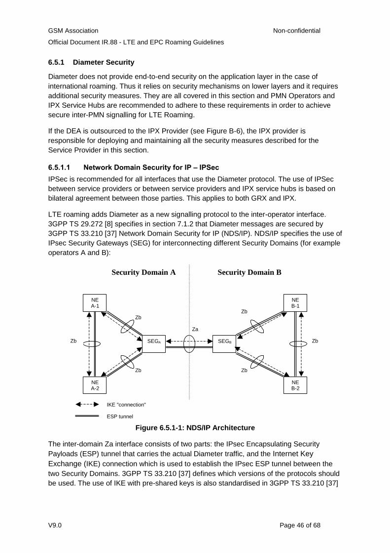
GSM Association Non-confidential
Official Document IR.88 - LTE and EPC Roaming Guidelines
V9.0 Page 46 of 68
6.5.1 Diameter Security
Diameter does not provide end-to-end security on the application layer in the case of
international roaming. Thus it relies on security mechanisms on lower layers and it requires
additional security measures. They are all covered in this section and PMN Operators and
IPX Service Hubs are recommended to adhere to these requirements in order to achieve
secure inter-PMN signalling for LTE Roaming.
If the DEA is outsourced to the IPX Provider (see Figure B-6), the IPX provider is
responsible for deploying and maintaining all the security measures described for the
Service Provider in this section.
6.5.1.1 Network Domain Security for IP – IPSec
IPSec is recommended for all interfaces that use the Diameter protocol. The use of IPSec
between service providers or between service providers and IPX service hubs is based on
bilateral agreement between those parties. This applies to both GRX and IPX.
LTE roaming adds Diameter as a new signalling protocol to the inter-operator interface.
3GPP TS 29.272 [8] specifies in section 7.1.2 that Diameter messages are secured by
3GPP TS 33.210 [37] Network Domain Security for IP (NDS/IP). NDS/IP specifies the use of
IPsec Security Gateways (SEG) for interconnecting different Security Domains (for example
operators A and B):
Za
Zb
Zb
Zb
SEGA
Security Domain A Security Domain B
SEGB
NEA-1
NEA-2
Zb
Zb
Zb
NEB-1
NEB-2
IKE "connection"
ESP tunnel
Figure 6.5.1-1: NDS/IP Architecture
The inter-domain Za interface consists of two parts: the IPsec Encapsulating Security
Payloads (ESP) tunnel that carries the actual Diameter traffic, and the Internet Key
Exchange (IKE) connection which is used to establish the IPsec ESP tunnel between the
two Security Domains. 3GPP TS 33.210 [37] defines which versions of the protocols should
be used. The use of IKE with pre-shared keys is also standardised in 3GPP TS 33.210 [37]
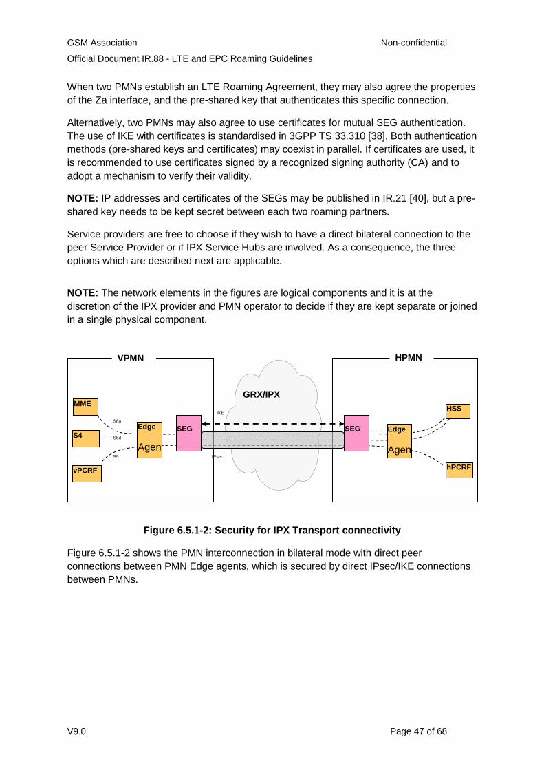
GSM Association Non-confidential
Official Document IR.88 - LTE and EPC Roaming Guidelines
V9.0 Page 47 of 68
When two PMNs establish an LTE Roaming Agreement, they may also agree the properties
of the Za interface, and the pre-shared key that authenticates this specific connection.
Alternatively, two PMNs may also agree to use certificates for mutual SEG authentication.
The use of IKE with certificates is standardised in 3GPP TS 33.310 [38]. Both authentication
methods (pre-shared keys and certificates) may coexist in parallel. If certificates are used, it
is recommended to use certificates signed by a recognized signing authority (CA) and to
adopt a mechanism to verify their validity.
NOTE: IP addresses and certificates of the SEGs may be published in IR.21 [40], but a pre-
shared key needs to be kept secret between each two roaming partners.
Service providers are free to choose if they wish to have a direct bilateral connection to the
peer Service Provider or if IPX Service Hubs are involved. As a consequence, the three
options which are described next are applicable.
NOTE: The network elements in the figures are logical components and it is at the
discretion of the IPX provider and PMN operator to decide if they are kept separate or joined
in a single physical component.
Figure 6.5.1-2: Security for IPX Transport connectivity
Figure 6.5.1-2 shows the PMN interconnection in bilateral mode with direct peer
connections between PMN Edge agents, which is secured by direct IPsec/IKE connections
between PMNs.
S6d
S6a
S9
GRX/IPX
VPMN HPMN
HSS
hPCRF
Edge
Agen
t
MME
S4
vPCRF
Edge
Agen
t
SEG SEG
IPsec
Tunn
IKE
Con
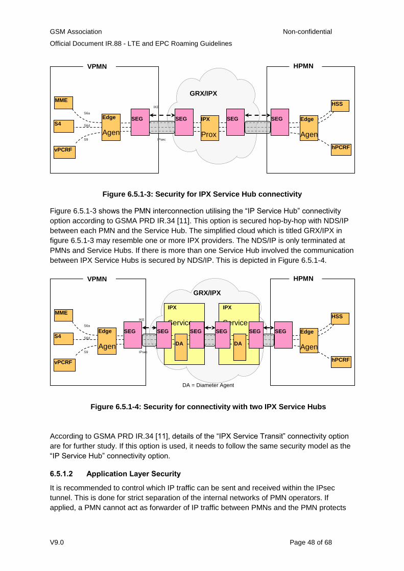
GSM Association Non-confidential
Official Document IR.88 - LTE and EPC Roaming Guidelines
V9.0 Page 48 of 68
Figure 6.5.1-3: Security for IPX Service Hub connectivity
Figure 6.5.1-3 shows the PMN interconnection utilising the “IP Service Hub” connectivity
option according to GSMA PRD IR.34 [11]. This option is secured hop-by-hop with NDS/IP
between each PMN and the Service Hub. The simplified cloud which is titled GRX/IPX in
figure 6.5.1-3 may resemble one or more IPX providers. The NDS/IP is only terminated at
PMNs and Service Hubs. If there is more than one Service Hub involved the communication
between IPX Service Hubs is secured by NDS/IP. This is depicted in Figure 6.5.1-4.
Figure 6.5.1-4: Security for connectivity with two IPX Service Hubs
According to GSMA PRD IR.34 [11], details of the “IPX Service Transit” connectivity option
are for further study. If this option is used, it needs to follow the same security model as the
“IP Service Hub” connectivity option.
6.5.1.2 Application Layer Security
It is recommended to control which IP traffic can be sent and received within the IPsec
tunnel. This is done for strict separation of the internal networks of PMN operators. If
applied, a PMN cannot act as forwarder of IP traffic between PMNs and the PMN protects
S6d
S6a
S9
GRX/IPX
VPMN HPMN
HSS
hPCRF
Edge
Agen
t
MME
S4
vPCRF
Edge
Agen
t
SEG SEG
IPsec
Tunn
IKE
Con SEG SEG IPX
Prox
y
S6d
S6a
S9
IPX
Service
Hub 2
GRX/IPX
VPMN HPMN
HSS
hPCRF
Edge
Agen
t
MME
S4
vPCRF
Edge
Agen
t
SEG SEG
IPsec
Tunn
IPX
Service
Hub 1 SEG SEG SEG SEG
IKE
DA DA
DA = Diameter Agent
GSM Association Non-confidential
Official Document IR.88 - LTE and EPC Roaming Guidelines
V9.0 Page 49 of 68
itself from unwanted traffic. The SEG (or another element at the network edge) should apply
the following IP filters.
There are different filters for the bilateral mode (see Figures 6.5.1-2, B-1, B-2, B-3, and B-
4), and for the transit mode (see Figures 6.5.1-3, B-5, and B-6). For bilateral mode allowed
IP addresses of the peer should be taken from the IR.21 RAEX DB. For transit mode peer
IP addresses should be provided by the IPX provider.
[SP] IP filters for bilateral mode:
Incoming IP packets should originate from the range of IP addresses which belong to the
peer PMN at which the IPsec tunnel terminates.
The destination IP address of incoming IP packets should belong to the range of IP
addresses of the PMN which receives the packet.
Outgoing IP packets should originate from the range of IP addresses of the PMN which
sends the packet.
The destination IP address of outgoing IP packets should belong to the range of IP
addresses which belong to the peer PMN at which the IPsec tunnel terminates.
[SP] IP filters for transit mode:
Incoming IP packets should originate from one of the IP addresses of the Diameter
Agents of the IPX Hub which is the peer of the IPsec tunnel.
The destination IP address of incoming IP packets should belong to the range of IP
addresses of the PMN which receives the packet.
Outgoing IP packets should originate from the range of IP addresses of the PMN which
sends the packet.
The destination IP address of outgoing IP packets should be one of the IP addresses of
the Diameter Agents of the IPX Hub which is the peer of the IPsec tunnel.
For further restriction, instead of allowing the entire range of IP addresses of a peer PMN or
IPX Hub, dedicated IP addresses of DEA can be used.
[ISH] IPX Hubs should also implement these filters. However, since IPX Hubs communicate
with Service Providers and with other IPX Hubs the filters differ in the sense that peer
networks are not only PMN, but also a set of PMNs which are managed by the peer IPX
Hub.
In the case where a PMN decides to outsource the DEA to their IPX-Provider (see Figure B-
6), and to deploy no IPsec tunnel because there is a direct link between the PMN and the
IPX provider which is not routed through the IPX or any other shared network, the IP filters
should be applied anyway. The Border Gateway or the Edge Router can do this.
On transport layer packets should be restricted to the Diameter protocol only.
6.5.1.3 Application Layer Security
Sanity checks on the application layer are required to only process allowable messages.
The following should be done:
GSM Association Non-confidential
Official Document IR.88 - LTE and EPC Roaming Guidelines
V9.0 Page 50 of 68
[SP, ISH] Filter Diameter messages to accept only supported Application IDs,
Command Codes and AVPs. Custom AVPs are not allowed by default. If they are
needed, they need to be agreed bilaterally.
[SP, ISH] Compare all AVP that identify the origin and the destination (that i
Origin/Destination Realm/Host and Visited PMN ID) to determine consistency
between them.
[SP] Verify CER/CEA Diameter Messages against Diameter Servers and capabilities
declared in IR.21 RAEX DB.
[SP] Check if Origin Realm/Host and/or Visited PMN ID is from a PMN which has a
roaming agreement with own PMN. Information related to this PMN is taken from
IR.21 RAEX DB during provisioning of the ACL in the DEA.
[SP, ISH] Check if the Route Record AVPs (if they exist) are sound in that the
documented route is possible for the source and destination given in the message.
[SP] Egress Diameter messages are received by the DEA from an internal network
element. They are only sent to their destination if all the AVPs which determine the
origin are addressing a network element within the sending (i.e. one’s own) PMN.
[SP] Ingress Diameter messages are received by the DEA from an external network
element. They are only sent to their destination if all the AVPs which determine the
destination are addressing a recipient which is inside one’s own PMN.
[SP] “Stateful“ inspection which only permits ingress messages in a defined order,
according to IETF RFC 3588 [3] states (e.g. no answer can be received if no request
has been issued).
[SP] Some AVP which may disclose internal information of a PMN but which is not
required outside the PMN should be changed/removed from all egress messages
(“topology hiding”). The general rules applied should be:
o To hide all Diameter Host Names.
o To hide the number of Diameter Nodes in the network by hiding routing and
identity details.
The DEA should determine messages to apply topology hiding based on:
o Their connection type and origin.
o Application Routing Rules-like criteria: Application-ID, Origin-Realm, Origin-
Host, Destination-Realm, Destination-Host.
In addition, topology hiding should also prevent other networks from determining the
routing used within a network by hiding the path that Diameter messages use when
being routed through the network. This is accomplished by:
o Hiding Diameter names in Route-Record AVP and using generic names in
their place.
o Reinserting the correct names if the request reenters the home network.
GSM Association Non-confidential
Official Document IR.88 - LTE and EPC Roaming Guidelines
V9.0 Page 51 of 68
o Hiding Diameter host names in other base Diameter AVPs such as: Session-
ID and Proxy-Info.
To prevent other networks from discovering the number of HSS in the network and
their identity, topology hiding should hide:
o Diameter name in Origin-Host AVP in requests from HSS to foreign MME.
o Diameter name in Origin-Host AVP for answers from HSS to foreign MME.
Likewise, to prevent other networks from discovering the number of MMEs in the
network and their identity, topology hiding should:
o Hide Diameter name in Origin-Host AVP in requests from MME to foreign
HSS
o Re-insert Host ID in Destination-Host AVP in requests from foreign HSS to
MME
o Hide Diameter name in Origin-Host in answer message from MME to foreign
HSS
6.5.1.4 Cross-Layer Security
There is a need to validate IP addresses against Diameter AVPs. Validation differs between
bilateral mode and transit mode.
Bilateral mode:
[SP] Check if the source IP address of ingress IP packets matches the IP address
range of the PMN which is identified in the Origin Realm/Host AVP and/or in the
Visited PMN ID AVP of the Diameter header in the message.
[SP] Vice versa, check if the destination IP address of ingress messages matches
the IP address range of the PMN which is identified in the Destination Realm/Host
AVP of the Diameter header in the message.
[SP] IP addresses and Diameter AVPs should also be checked against the entries in
the IR.21 RAEX DB.
Transit mode:
[SP] At the PMN edge, check if the source IP address of ingress IP packets matches
the IP address of the IPX Hub’s DEA via which messages from the source PMN are
received. The source PMN is identified by Origin Realm/Host and/or Visited PMN ID
in the message.
[SP] Vice versa, at the PMN edge, check if the destination IP address of egress IP
packets matches the IP address of the IPX Hub’s DEA via which messages are sent
to the destination PMN. The destination PMN is identified by Destination Realm/Host
and/or Visited PMN ID in the message.
[ISH] The IPX Hub is required to make sure that it performs the cross layer checks
on behalf of the PMN in a similar way as described for the bilateral mode above. For
GSM Association Non-confidential
Official Document IR.88 - LTE and EPC Roaming Guidelines
V9.0 Page 52 of 68
an IPX Hub, the peer cannot only be a Service Provider. Another IPX Hub can be
the peer as well. The above cross layer checks are to be adapted accordingly.
In addition, there are other controls that a DEA should support in both modes:
[SP, ISH] The DEA should implement anti-spoofing mechanisms for all Diameter
applications.
[SP] The DEA should not forward traffic from one external network interface to
another. It only forwards traffic from an internal to an external interface or the other
way round.
6.5.2.5 Discovery of Peer PLMN Network Elements
According to Section 3.1.3.4 there are two possible mechanisms to discover the “next hop”:
Manually configured static entries in the Peer and Routing Tables;
Dynamic Discovery using DNS (S)NAPTR.
From a security perspective it is recommended to use static entries. The use of dynamic
discovery of DEA peers raises several security issues mainly if a GRX/IPX DNS is used.
More details are discussed in Appendix C. If dynamic DEA discovery is chosen, the
following requirements should be met by the DEA:
[SP] The peer and routing table entries created via DNS should expire (or be
refreshed) within the DNS TTL. According to IETF RFC 3588 [3], the routing table
entry’s expiration should match the peer’s expiration value in the peer table.
[SP] DNS RRs (Resource Record) should be validated via DNSSEC to protect
against DNS-vectored attacks.
[SP] The ACLs defined in Section 6.5.2.3 should be applied in order to verify
roaming agreement and authorization for the DEA peer to act in the declared role for
the declared capabilities.
[SP] Security mechanisms should be implemented to protect DEA against DNS
reflection/amplification attacks (see Annex C for more details).
6.6 Hubbing
The Hubbing Architecture for LTE has not been defined in GSMA.
EDITOR'S NOTE: Future work on the hubbing architecture for LTE is expected and this
section will be updated accordingly when the work is complete.
6.7 Default APN
The default APN can be set either to the IMS well-known APN or to an APN other than the
IMS well-known APN, as described in section Error! Reference source not found.. The
consequences of selecting the one or the other APN as Default APN are as follows:
If the default APN in the HSS is set to the IMS well-known APN, then
GSM Association Non-confidential
Official Document IR.88 - LTE and EPC Roaming Guidelines
V9.0 Page 53 of 68
A PDN connection to the IMS well-known APN is always established during the E-UTRAN initial attach for UE that supports GSMA PRD IR.92 [30], independent of whether the user is subscribed to any IMS service or not.
A PDN connection to the IMS well-known APN is always established during the E-UTRAN initial attach for UE that does not support GSMA PRD IR.92 [30] and that does not provide an APN.
The UE (which gets connected to the IMS well-known APN) needs to establish an additional PDN connection to an APN other than the IMS well-known APN in order to use non-IMS services, for example, to access the Internet, and is charged accordingly.
NOTE: The IMS well-known APN works in this scenario as a zero-charging “dummy” APN
for the user that is not subscribed to any IMS service, that is, the UE is connected to the
EPC but it is not able to use any data service.
If the default APN in the HSS is set to another APN than the IMS well-known APN, then
A PDN connection to the IMS well-known APN is never established during the E-UTRAN initial attach for UE that supports GSMA PRD IR.92 [30], independent of whether the user is subscribed to any IMS service or not.
A PDN connection to such default APN is always established during the E-UTRAN initial attach for a UE that does not provide an APN during initial attach, for example, for a UE that supports IR92 [30].
The UE that supports GSMA PRD IR.92 [30] and which gets connected to such default APN needs to establish an additional PDN connection to the IMS well-known APN to use IMS services as specified in GSMA PRD IR.92 [30].
The UE (which gets connected to such default APN) is able to use the APN other than the IMS well-known APN for its purpose, for example, in case the default APN is configured to be the one used for Internet access, then the UE can access the Internet using the PDN connection that is established during the E-UTRAN initial attach.
Unwanted data charging may occur on the PDN Connection to the APN other than the IMS well-known APN if the UE is configured to not use data when roaming, unless that APN other than the IMS well-known APN is a zero-charging APN.
Independent of being configured as the default APN or not, the IMS well-known APN is
zero-charged on packet-level for some or all IMS services in case of local breakout (see
PRD IR.65 [31]) and must not be used by any non-IMS application (see PRD IR.92 [30]).
However charging for the amount of data transferred may occur if the PDN connection to
the IMS well-known APN is
Home routed and used for IMS services.
Used for IMS services that are not zero-charged on packet-level.
GSM Association Non-confidential
Official Document IR.88 - LTE and EPC Roaming Guidelines
V9.0 Page 54 of 68
6A Technical Requirements for static QoS support
6A.1 Home Routed architecture and S8 protocol is GTP
This section illustrates the required functionality that is needed in the VPMN and the HPMN
in order to support static QoS for LTE roaming. Static QoS refers to the QoS that is provided
for the Default Bearer that is set up for any PDN connection that is requested by a roaming
UE.
Support of static QoS whilst roaming has two aspects:
1. Ensuring that the QoS parameters of an inbound roamer are within the limits of the roaming agreement.
2. Enforcement of the actual QoS by the VPMN.
6A.1.1 Limiting QoS for inbound roamers to the limits of the roaming agreement
6A.1.1.1 Requirements for the VPMN
In order to ensure that a PDN connection can be established successfully while at the same
time not violating the QoS policies of the VPMN for inbound roamers from a given HPMN,
the following functionality is required for the VPMN:
When an inbound roaming UE performs an Attach, the MME/S4-SGSN of the VPMN shall, upon having received the inbound roamer’s subscription from the HSS, compare the QCI, the ARP, and the APN-AMBR value as contained in the subscription for the chosen APN with the pre-configured range of supported QCIs and ARPs and the supported range of APN-AMBR values for the HPMN. (Note: These ranges are configured based on the roaming agreement with the respective HPMN.)
In case the MME/S4-SGSN detects that a value is outside those ranges, the MME/S4-SGSN shall change/downgrade the related value to a configured default value for the related HPMN (see also TS 23.401, section 4.7.2.1). If the QCI, ARP and APN-AMBR values are in line with the roaming agreement, then the MME/S4-SGSN shall accept these values.
The same requirements apply when a roaming UE requests another PDN connection using
the UE requested additional PDN connectivity procedure or when the HPMN updates the
subscription of the outbound roamer using the HSS Initiated Subscribed QoS Modification
procedure.
6A.1.1.2 Requirements for the HPMN
In order to ensure that a PDN connection can be established successfully, the following
functionality is required for the HPMN:
When a roaming UE performs an Attach, requests an additional PDN connection or if the HPMN updates the subscription using the HSS Initiated Subscribed QoS Modification procedure, then the HPMN shall accept the QoS values (QCI, ARP, APN-AMBR) as received from the VPMN, that is, the HPMN shall not change the QoS values received from the VPMN during the Attach, the UE requested additional PDN connectivity or the HSS Initiated Subscribed QoS Modification procedure.
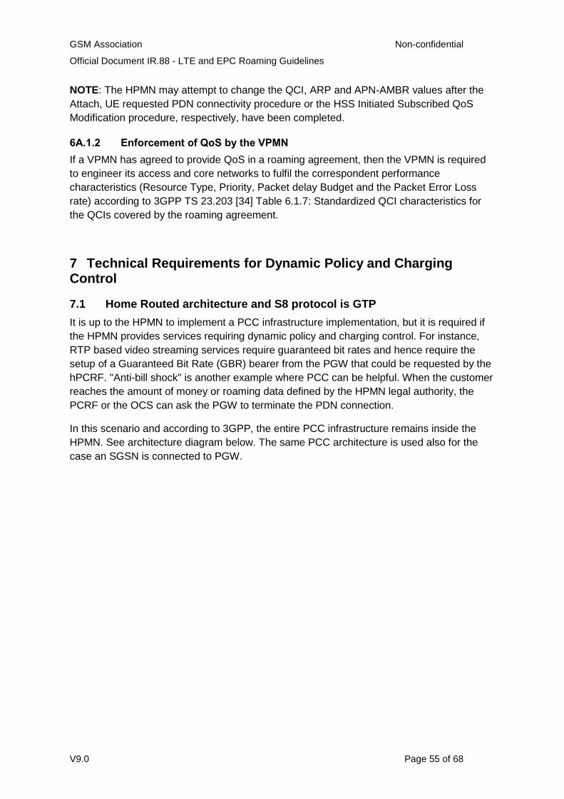
GSM Association Non-confidential
Official Document IR.88 - LTE and EPC Roaming Guidelines
V9.0 Page 55 of 68
NOTE: The HPMN may attempt to change the QCI, ARP and APN-AMBR values after the
Attach, UE requested PDN connectivity procedure or the HSS Initiated Subscribed QoS
Modification procedure, respectively, have been completed.
6A.1.2 Enforcement of QoS by the VPMN
If a VPMN has agreed to provide QoS in a roaming agreement, then the VPMN is required
to engineer its access and core networks to fulfil the correspondent performance
characteristics (Resource Type, Priority, Packet delay Budget and the Packet Error Loss
rate) according to 3GPP TS 23.203 [34] Table 6.1.7: Standardized QCI characteristics for
the QCIs covered by the roaming agreement.
7 Technical Requirements for Dynamic Policy and Charging Control
7.1 Home Routed architecture and S8 protocol is GTP
It is up to the HPMN to implement a PCC infrastructure implementation, but it is required if
the HPMN provides services requiring dynamic policy and charging control. For instance,
RTP based video streaming services require guaranteed bit rates and hence require the
setup of a Guaranteed Bit Rate (GBR) bearer from the PGW that could be requested by the
hPCRF. "Anti-bill shock" is another example where PCC can be helpful. When the customer
reaches the amount of money or roaming data defined by the HPMN legal authority, the
PCRF or the OCS can ask the PGW to terminate the PDN connection.
In this scenario and according to 3GPP, the entire PCC infrastructure remains inside the
HPMN. See architecture diagram below. The same PCC architecture is used also for the
case an SGSN is connected to PGW.
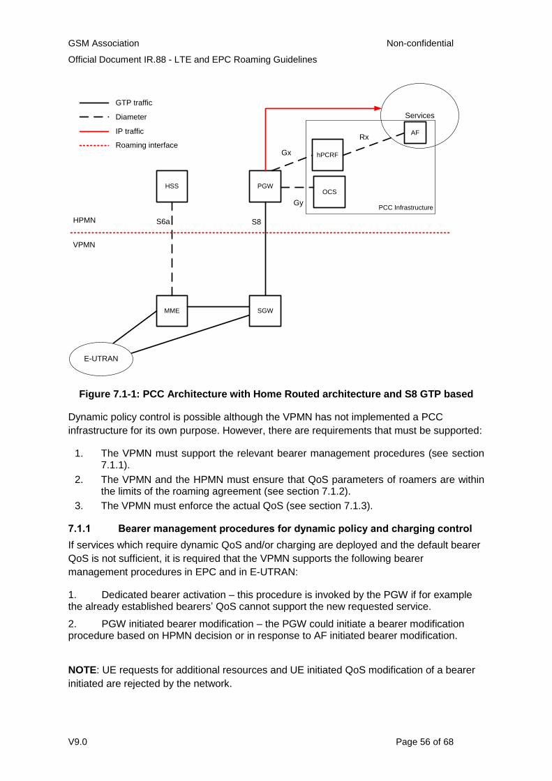
GSM Association Non-confidential
Official Document IR.88 - LTE and EPC Roaming Guidelines
V9.0 Page 56 of 68
PCC Infrastructure
Services
HSS
MME
PGW
hPCRF
S6a S8
VPMN
HPMN
E-UTRAN
OCS
GTP traffic
Diameter
IP traffic
Roaming interface
SGW
Gy
Gx
RxAF
Figure 7.1-1: PCC Architecture with Home Routed architecture and S8 GTP based
Dynamic policy control is possible although the VPMN has not implemented a PCC
infrastructure for its own purpose. However, there are requirements that must be supported:
1. The VPMN must support the relevant bearer management procedures (see section 7.1.1).
2. The VPMN and the HPMN must ensure that QoS parameters of roamers are within the limits of the roaming agreement (see section 7.1.2).
3. The VPMN must enforce the actual QoS (see section 7.1.3).
7.1.1 Bearer management procedures for dynamic policy and charging control
If services which require dynamic QoS and/or charging are deployed and the default bearer
QoS is not sufficient, it is required that the VPMN supports the following bearer
management procedures in EPC and in E-UTRAN:
1. Dedicated bearer activation – this procedure is invoked by the PGW if for example the already established bearers’ QoS cannot support the new requested service.
2. PGW initiated bearer modification – the PGW could initiate a bearer modification procedure based on HPMN decision or in response to AF initiated bearer modification.
NOTE: UE requests for additional resources and UE initiated QoS modification of a bearer
initiated are rejected by the network.
GSM Association Non-confidential
Official Document IR.88 - LTE and EPC Roaming Guidelines
V9.0 Page 57 of 68
7.1.2 Limiting QoS for inbound roamers to the limits of the roaming agreement
7.1.2.1 Requirements for the VPMN
When receiving a Dedicated bearer activation request from the HPMN, the VPMN’s
MME/S4-SGSN shall compare the QCI, ARP, GBR and MBR values contained in the
request with the pre-configured range of supported QCI, ARP, GBR and MBR values for the
HPMN. (Note: theses ranges are configured based on the roaming agreement with the
respective HPMN.) In case the MME/S4-SGSN detects that a value is outside those ranges,
the MME/S4-SGSN shall reject the dedicated bearer activation request; otherwise, the
MME/S4-SGSN shall accept the request.
When receiving a PDN-GW initiated bearer modification request, the VPMN’s MME/S4-
SGSN shall compare the QoS values contained in the request (QCI, ARP and APN-AMBR
or GBR and MBR for non-GBR bearers or GBR bearers, respectively) with the pre-
configured range of supported QCI, ARP, APN-AMBR, GBR and MBR values for the
HPMN. (Note: these ranges are configured based on the roaming agreement with the
respective HPMN.) In case the MME/S4-SGSN detects that a value is outside those ranges,
the MME/S4-SGSN shall reject the PDN-GW initiated bearer modification request.
When a roaming UE requests additional resources or requests modification of resources
using the UE requested bearer resource modification request and the VPMN supports UE
requested bearer resource modification requests, then this triggers a dedicated bearer
activation or a PDN-GW initiated bearer modification by the HPMN. In this case, the
MME/S4-SGSN shall behave accordingly as described in the previous two paragraphs.
7.1.2.2 Requirements for the HPMN
When a Policy and Charging infrastructure is deployed in the HPMN, then the HPMN’s
PCRF provides the QoS parameters to the HPMN’s PDN-GW, which are in turn sent to the
VPMN as part of all bearer management procedures listed in section 7.1.1.
In order to ensure that the requested QoS sent to a VPMN is within the limits of the roaming
agreement, the HPMN’s PCRF shall – in case of an outbound roamer - only provide QoS
parameters (QCI, ARP, APN-AMBR or GBR and MBR, respectively) to the HPMN’s PDN-
GW, which are within the limits of the roaming agreement with the respective VPMN.
7.1.3 Enforcement of QoS by the VPMN If a VPMN has agreed to enforce QoS in a roaming agreement, then the VPMN is required
To engineer its access and core networks to fulfil the correspondent performance characteristics (Resource Type, Priority, Packet delay Budget and the Packet Error Loss rate) according to 3GPP TS 23.203 [34] Table 6.1.7: Standardized QCI characteristics for the QCIs covered by the roaming agreement.
To support GBR bearers and provide the requested guaranteed bit rates within the limits as agreed as part of the roaming agreement.
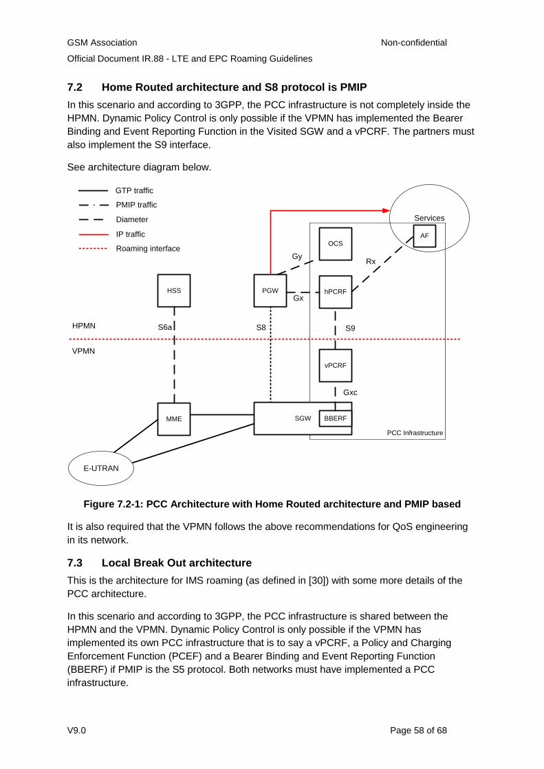
GSM Association Non-confidential
Official Document IR.88 - LTE and EPC Roaming Guidelines
V9.0 Page 58 of 68
7.2 Home Routed architecture and S8 protocol is PMIP
In this scenario and according to 3GPP, the PCC infrastructure is not completely inside the
HPMN. Dynamic Policy Control is only possible if the VPMN has implemented the Bearer
Binding and Event Reporting Function in the Visited SGW and a vPCRF. The partners must
also implement the S9 interface.
See architecture diagram below.
PCC Infrastructure
Services
HSS
MME
PGW hPCRF
S6a S8
VPMN
HPMN
E-UTRAN
OCS
PMIP traffic
Diameter
IP traffic
Roaming interface
SGW
Gy
Gx
Rx
AF
BBERF
vPCRF
S9
Gxc
GTP traffic
Figure 7.2-1: PCC Architecture with Home Routed architecture and PMIP based
It is also required that the VPMN follows the above recommendations for QoS engineering
in its network.
7.3 Local Break Out architecture
This is the architecture for IMS roaming (as defined in [30]) with some more details of the
PCC architecture.
In this scenario and according to 3GPP, the PCC infrastructure is shared between the
HPMN and the VPMN. Dynamic Policy Control is only possible if the VPMN has
implemented its own PCC infrastructure that is to say a vPCRF, a Policy and Charging
Enforcement Function (PCEF) and a Bearer Binding and Event Reporting Function
(BBERF) if PMIP is the S5 protocol. Both networks must have implemented a PCC
infrastructure.
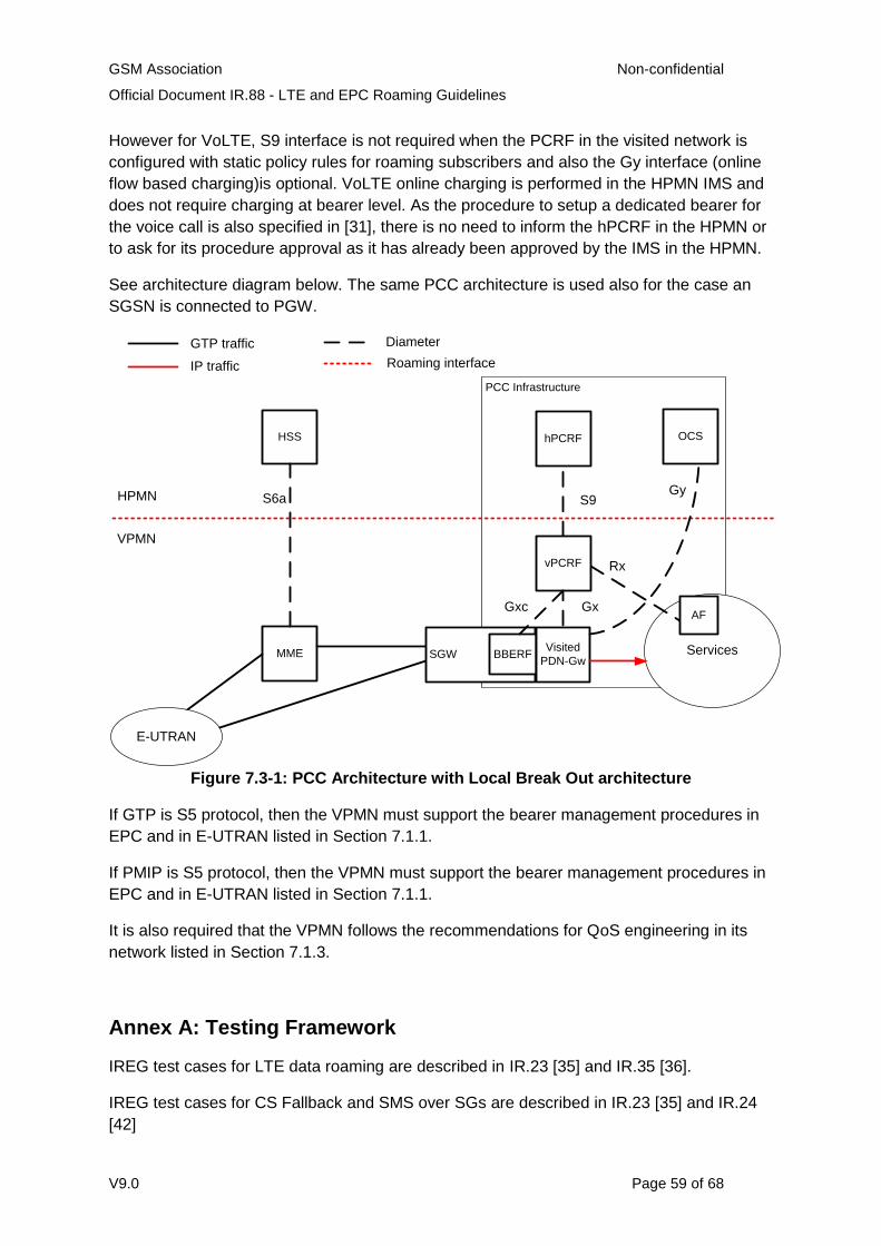
GSM Association Non-confidential
Official Document IR.88 - LTE and EPC Roaming Guidelines
V9.0 Page 59 of 68
However for VoLTE, S9 interface is not required when the PCRF in the visited network is
configured with static policy rules for roaming subscribers and also the Gy interface (online
flow based charging)is optional. VoLTE online charging is performed in the HPMN IMS and
does not require charging at bearer level. As the procedure to setup a dedicated bearer for
the voice call is also specified in [31], there is no need to inform the hPCRF in the HPMN or
to ask for its procedure approval as it has already been approved by the IMS in the HPMN.
See architecture diagram below. The same PCC architecture is used also for the case an
SGSN is connected to PGW.
PCC Infrastructure
Services
HSS
MME
hPCRF
S6a
VPMN
HPMN
E-UTRAN
OCS
GTP traffic Diameter
IP traffic Roaming interface
SGW
Gy
Gx
Rx
AF
BBERF
vPCRF
S9
Gxc
Visited
PDN-Gw
Figure 7.3-1: PCC Architecture with Local Break Out architecture
If GTP is S5 protocol, then the VPMN must support the bearer management procedures in
EPC and in E-UTRAN listed in Section 7.1.1.
If PMIP is S5 protocol, then the VPMN must support the bearer management procedures in
EPC and in E-UTRAN listed in Section 7.1.1.
It is also required that the VPMN follows the recommendations for QoS engineering in its
network listed in Section 7.1.3.
Annex A: Testing Framework
IREG test cases for LTE data roaming are described in IR.23 [35] and IR.35 [36].
IREG test cases for CS Fallback and SMS over SGs are described in IR.23 [35] and IR.24
[42]
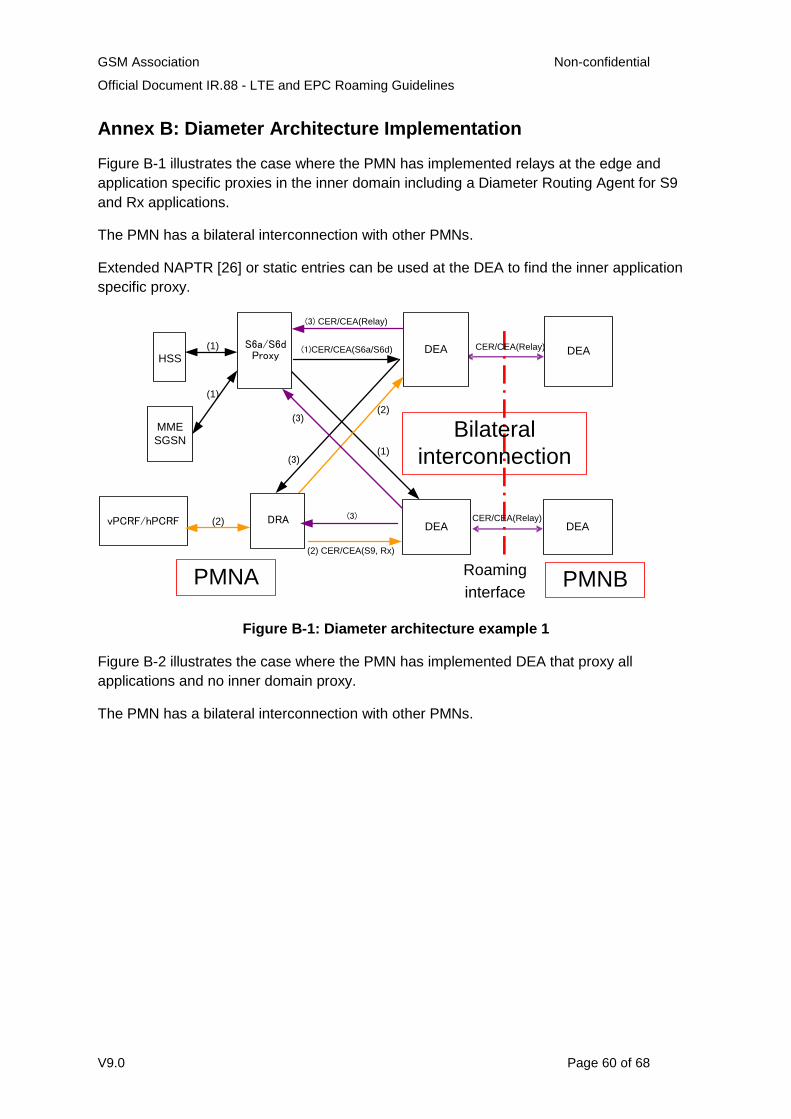
GSM Association Non-confidential
Official Document IR.88 - LTE and EPC Roaming Guidelines
V9.0 Page 60 of 68
Annex B: Diameter Architecture Implementation
Figure B-1 illustrates the case where the PMN has implemented relays at the edge and
application specific proxies in the inner domain including a Diameter Routing Agent for S9
and Rx applications.
The PMN has a bilateral interconnection with other PMNs.
Extended NAPTR [26] or static entries can be used at the DEA to find the inner application
specific proxy.
(1)CER/CEA(S6a/S6d)
(2) CER/CEA(S9, Rx)
Roaming
interface
(2)
HSS
MME
SGSN
vPCRF/hPCRF DEADEA
DEA DEA
PMNA PMNB
CER/CEA(Relay)
(1)
Bilateral
interconnection
CER/CEA(Relay)
S6a/S6d Proxy
DRA(2)
(1)
(1)
(3) CER/CEA(Relay)
(3)
(3)
(3)
Figure B-1: Diameter architecture example 1
Figure B-2 illustrates the case where the PMN has implemented DEA that proxy all
applications and no inner domain proxy.
The PMN has a bilateral interconnection with other PMNs.
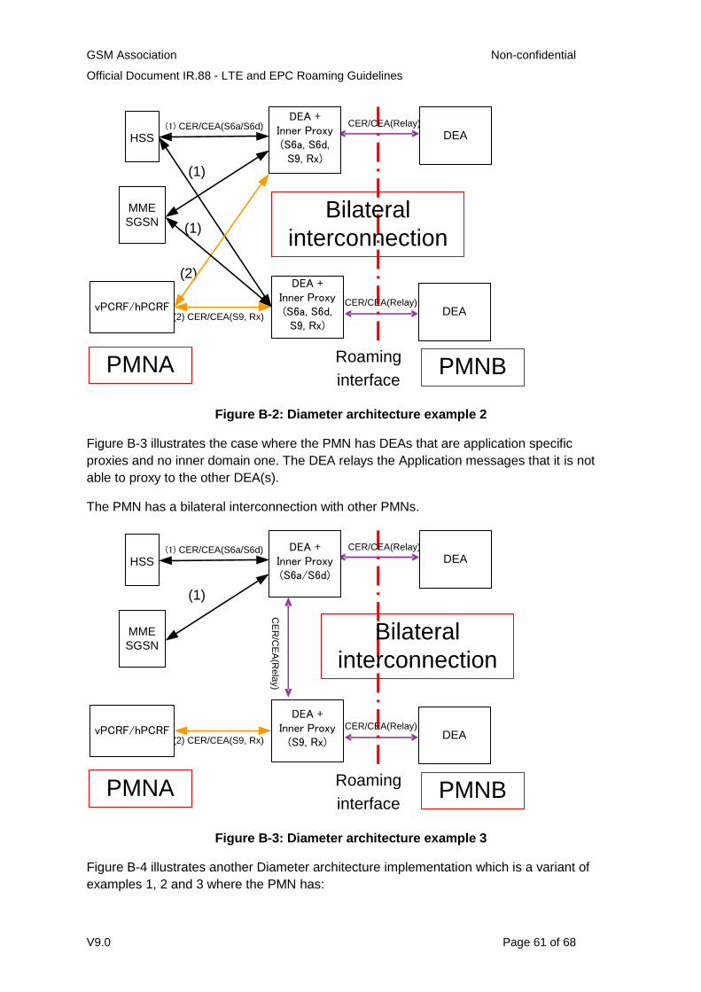
GSM Association Non-confidential
Official Document IR.88 - LTE and EPC Roaming Guidelines
V9.0 Page 61 of 68
(1) CER/CEA(S6a/S6d)
(2) CER/CEA(S9, Rx)
Roaming
interface
(2)
HSS
MME
SGSN
vPCRF/hPCRF DEA
DEA +Inner Proxy (S6a, S6d, S9, Rx)
DEA
PMNA PMNB
CER/CEA(Relay)
(1)
Bilateral
interconnection
CER/CEA(Relay)
(1)
DEA +Inner Proxy (S6a, S6d, S9, Rx)
Figure B-2: Diameter architecture example 2
Figure B-3 illustrates the case where the PMN has DEAs that are application specific
proxies and no inner domain one. The DEA relays the Application messages that it is not
able to proxy to the other DEA(s).
The PMN has a bilateral interconnection with other PMNs.
(1) CER/CEA(S6a/S6d)
(2) CER/CEA(S9, Rx)
Roaming
interface
HSS
MME
SGSN
vPCRF/hPCRF DEA
DEA + Inner Proxy(S6a/S6d)
DEA
PMNA PMNB
CER/CEA(Relay)
(1)
Bilateral
interconnection
CER/CEA(Relay)
DEA + Inner Proxy
(S9, Rx)
CE
R/C
EA
(Re
lay)
Figure B-3: Diameter architecture example 3
Figure B-4 illustrates another Diameter architecture implementation which is a variant of
examples 1, 2 and 3 where the PMN has:
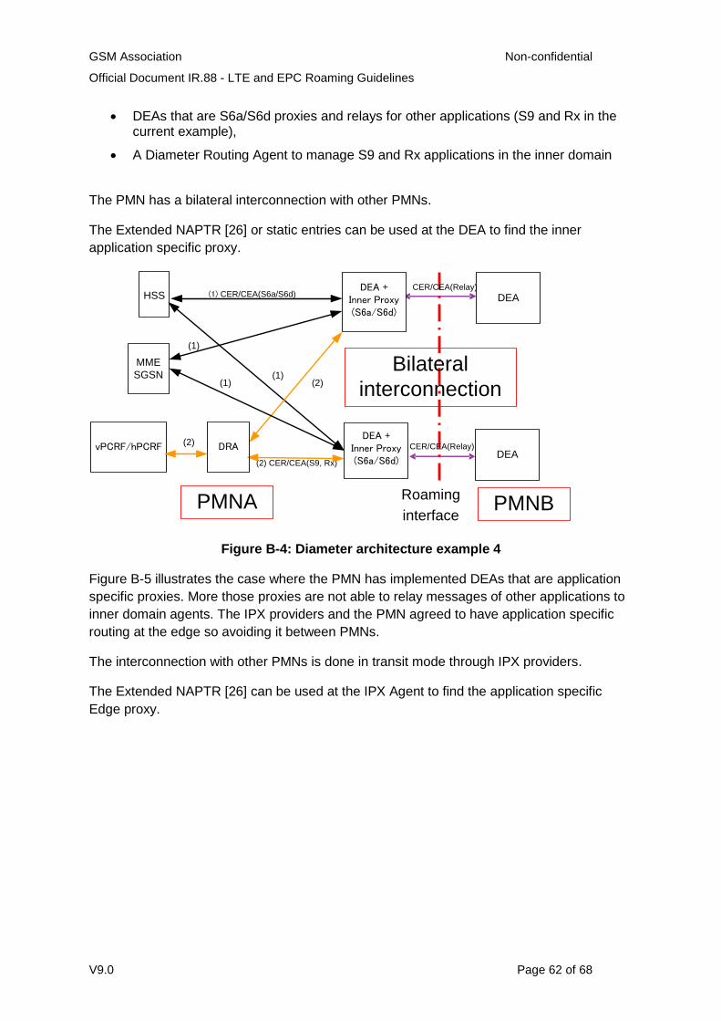
GSM Association Non-confidential
Official Document IR.88 - LTE and EPC Roaming Guidelines
V9.0 Page 62 of 68
DEAs that are S6a/S6d proxies and relays for other applications (S9 and Rx in the current example),
A Diameter Routing Agent to manage S9 and Rx applications in the inner domain
The PMN has a bilateral interconnection with other PMNs.
The Extended NAPTR [26] or static entries can be used at the DEA to find the inner
application specific proxy.
(1) CER/CEA(S6a/S6d)
(2) CER/CEA(S9, Rx)
Roaming
interface
(2)
HSS
MME
SGSN
vPCRF/hPCRF DEA
DEA + Inner Proxy(S6a/S6d)
DEA
PMNA PMNB
CER/CEA(Relay)
(1)
Bilateral
interconnection
CER/CEA(Relay)
(1)
DEA + Inner Proxy(S6a/S6d)
DRA
(1)
(2)
Figure B-4: Diameter architecture example 4
Figure B-5 illustrates the case where the PMN has implemented DEAs that are application
specific proxies. More those proxies are not able to relay messages of other applications to
inner domain agents. The IPX providers and the PMN agreed to have application specific
routing at the edge so avoiding it between PMNs.
The interconnection with other PMNs is done in transit mode through IPX providers.
The Extended NAPTR [26] can be used at the IPX Agent to find the application specific
Edge proxy.
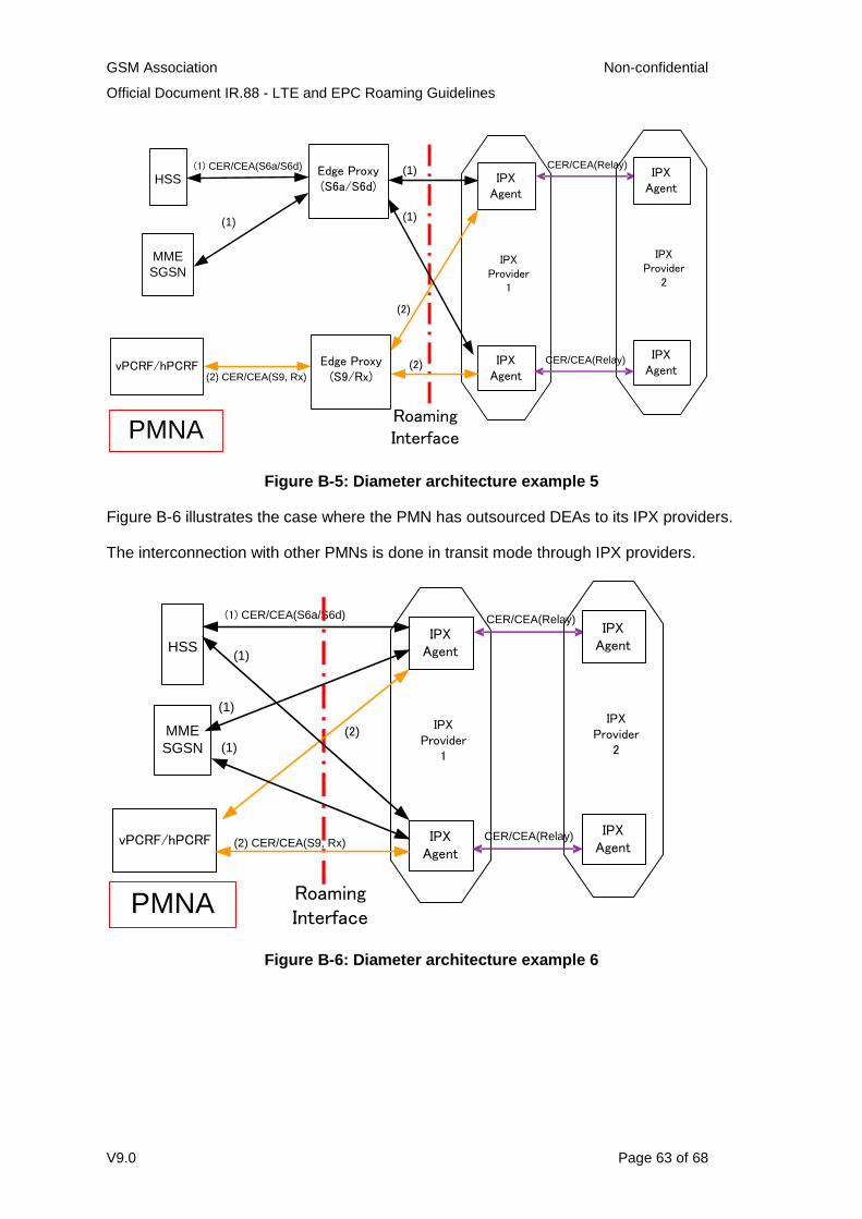
GSM Association Non-confidential
Official Document IR.88 - LTE and EPC Roaming Guidelines
V9.0 Page 63 of 68
(1) CER/CEA(S6a/S6d)
(2) CER/CEA(S9, Rx)
Roaming Interface
HSS
MME
SGSN
vPCRF/hPCRF
Edge Proxy(S6a/S6d)
PMNA
CER/CEA(Relay)
(1)
IPXAgent
IPXAgent
(1)
(1)
(2)
(2)
IPX Provider
1
IPXAgent
IPXAgent
IPX Provider
2
CER/CEA(Relay)Edge Proxy(S9/Rx)
Figure B-5: Diameter architecture example 5
Figure B-6 illustrates the case where the PMN has outsourced DEAs to its IPX providers.
The interconnection with other PMNs is done in transit mode through IPX providers.
(1) CER/CEA(S6a/S6d)
(2) CER/CEA(S9, Rx)
Roaming Interface
HSS
MME
SGSN
vPCRF/hPCRF
PMNA
CER/CEA(Relay)
IPXAgent
IPXAgent
(1)
(2)IPX
Provider1
IPXAgent
IPXAgent
IPX Provider
2
CER/CEA(Relay)
(1)
(1)
Figure B-6: Diameter architecture example 6
GSM Association Non-confidential
Official Document IR.88 - LTE and EPC Roaming Guidelines
V9.0 Page 64 of 68
Annex C: Background on Security Requirements
This annex provides some background information and justification for the security
requirements of Section 6.5.
The need for Diameter Security
Diameter IETF RFC 3588 [3] requires a TLS or IPSec tunnel at the network/transport layer
starting from a Diameter agent and terminating at the Diameter peer in order to ensure
authentication, data integrity and confidentiality (referred to as “peer-to-peer” security). In an
“Internet Scenario” this setting is possible. However, in international roaming, secure
tunnels are handled by SEGs and not by Diameter Agents. As a consequence there is no
“peer-to-peer” security.
When a TLS or IPSec tunnel is setup each agent has authenticated itself towards the peer
while data integrity and confidentiality is guaranteed over the entire network. In international
roaming these assumptions are not true:
Authentication is performed by SEGs and not by Diameter Agents. Consequently, a Diameter Agent establishes a “trusted” relationship with a peer during exchange capabilities process involving CER/CEA messages but it has no way to authenticate it. This point becomes even more crucial when dynamic peer discovery is used.
Diameter packets are not natively protected by encryption and integrity checks. This is acceptable for PMN-internal traffic because this network is trusted, Traffic to/from external networks requires protection, in contrast.
As a consequence, a PMN is exposed to several fraud/attack vulnerabilities if the
countermeasures described in section 6.5.2 are not applied.
DNS Security
The use of dynamic discovery for DEA peers raises several security issues related to DNS
vulnerabilities/attacks mainly when a GRX/IPX DNS, external to a PMN, is used. The
approach is only as good as the security of the DNS queries along the way. At least two
critical attacks to DNS infrastructure can be cited:
An amplification and/or reflection attack can overload (DoS) a victim DEA with a huge number of unsolicited DNS answers.
DNS Poisoning attack corrupts the association name/IP (i.e. Kaminsky attack). Once corrupted, the entry persists for a long time (TTL value). The result is that the DEA’s routing table is improperly altered.
So, from a security perspective it is recommended to use static entries; to simplify network
configuration management within a PMN, a centralized Diameter Redirect Agent (DRD,
IETF RFC 3588 [3]) can be used. In this case, peer and routing table entries can be
configured just once.

GSM Association Non-confidential
Official Document IR.88 - LTE and EPC Roaming Guidelines
V9.0 Page 65 of 68
Annex D: Document Management
Document History
Version Date Brief Description of Change Approval Authority
Editor / Company
0.0.20 7 Aug 2009 Initial version input for RILTE #3
0.0.22 21 Aug 2009
Baseline version following RILTE #3
0.0.24 24 Sept 2009
Baseline version following RILTE #4
0.0.26 12 Oct 2009
Consolidation of RILTE #4 Action Points and subsequent emails
0.0.28 20 Oct 2009
Version for review at RILTE #5
1.0 28 Oct 2009
Approved at RILTE #5, for submission to IREG #57
IREG #57 John Boggis, Vodafone
2.0 1 June 2010
Major restructure and addition of some new sections
IREG#58 EMC#84
John Boggis, Vodafone
3.0 21 October 2010
Inclusion of the following CRs:
MCR 002: 2G/3G and LTE Co-existence Scenarios
MCR 003: Document the roaming retry procedure for CSFB
MCR 004: Diameter Roaming Architecture
MCR 005: PMIP-GTP Interworking
MCR 006: Gateway Selection in SGSN
MCR 007: VoLTE Roaming Architecture Additions
IREG #59 DAG #77 EMC #89
Nick Russell, Vodafone
3.1 17 February 2011
Inclusion of mCR 008: LTE Voice Roaming Architecture
Packet #48 Nick Russell, Vodafone
4.0 21 March 2011
Inclusion of the following CRs:
MCR 009: IP addressing alignment
mCR 010: Clarification on IMS APN usage
Packet #48 IREG #60 DAG #79
Nick Russell, Vodafone
5.0 18 May 2011
Change of Editor, section numbering correction on 'Document Management' and Inclusion of the following CRs:
MCR 011: IMS APN and IMS Emergency call
MCR 013: Addition of details from the IPv6 EMC Task Force's Ipv6 Transition Whitepaper
MCR 014: IMS "well-known" APN as Default APN
Packet #50 IREG #60 DAG #81
Itsuma Tanaka, NTT DOCOMO
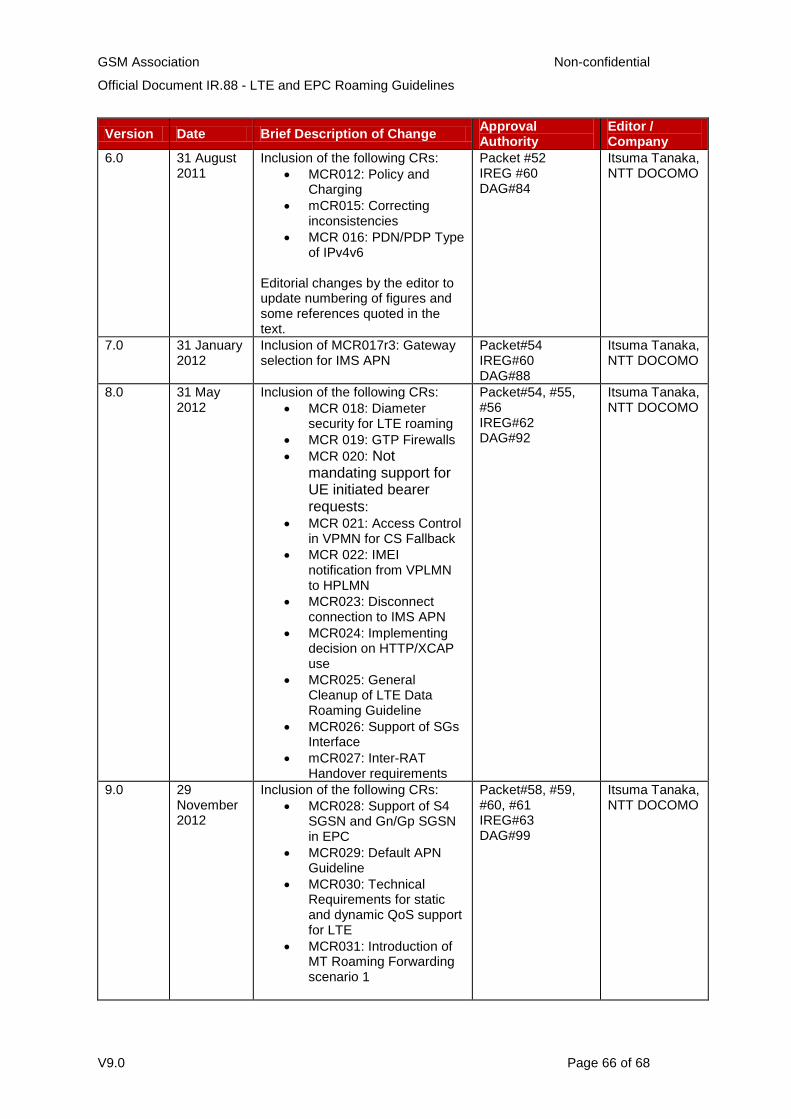
GSM Association Non-confidential
Official Document IR.88 - LTE and EPC Roaming Guidelines
V9.0 Page 66 of 68
Version Date Brief Description of Change Approval Authority
Editor / Company
6.0 31 August 2011
Inclusion of the following CRs:
MCR012: Policy and Charging
mCR015: Correcting inconsistencies
MCR 016: PDN/PDP Type of IPv4v6
Editorial changes by the editor to update numbering of figures and some references quoted in the text.
Packet #52 IREG #60 DAG#84
Itsuma Tanaka, NTT DOCOMO
7.0 31 January 2012
Inclusion of MCR017r3: Gateway selection for IMS APN
Packet#54 IREG#60 DAG#88
Itsuma Tanaka, NTT DOCOMO
8.0 31 May 2012
Inclusion of the following CRs:
MCR 018: Diameter security for LTE roaming
MCR 019: GTP Firewalls
MCR 020: Not mandating support for UE initiated bearer requests:
MCR 021: Access Control in VPMN for CS Fallback
MCR 022: IMEI notification from VPLMN to HPLMN
MCR023: Disconnect connection to IMS APN
MCR024: Implementing decision on HTTP/XCAP use
MCR025: General Cleanup of LTE Data Roaming Guideline
MCR026: Support of SGs Interface
mCR027: Inter-RAT Handover requirements
Packet#54, #55, #56 IREG#62 DAG#92
Itsuma Tanaka, NTT DOCOMO
9.0 29 November 2012
Inclusion of the following CRs:
MCR028: Support of S4 SGSN and Gn/Gp SGSN in EPC
MCR029: Default APN Guideline
MCR030: Technical Requirements for static and dynamic QoS support for LTE
MCR031: Introduction of MT Roaming Forwarding scenario 1
Packet#58, #59, #60, #61 IREG#63 DAG#99
Itsuma Tanaka, NTT DOCOMO
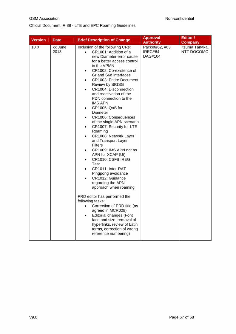
GSM Association Non-confidential
Official Document IR.88 - LTE and EPC Roaming Guidelines
V9.0 Page 67 of 68
Version Date Brief Description of Change Approval Authority
Editor / Company
10.0 xx June 2013
Inclusion of the following CRs:
CR1001: Addition of a new Diameter error cause for a better access control in the VPMN
CR1002: Co-existence of Gr and S6d interfaces
CR1003: Entire Document Review by SIGSG
CR1004: Disconnection and reactivation of the PDN connection to the IMS APN
CR1005: QoS for Diameter
CR1006: Consequences of the single APN scenario
CR1007: Security for LTE Roaming
CR1008: Network Layer and Transport Layer Filters
CR1009: IMS APN not as APN for XCAP (Ut)
CR1010: CSFB IREG Test
CR1011: Inter-RAT Pingpong avoidance
CR1012: Guidance regarding the APN approach when roaming
PRD editor has performed the following tasks:
Correction of PRD title (as agreed in MCR028)
Editorial changes (Font face and size, removal of hyperlinks, review of Latin terms, correction of wrong reference numbering)
Packet#62, #63 IREG#64 DAG#104
Itsuma Tanaka, NTT DOCOMO

GSM Association Non-confidential
Official Document IR.88 - LTE and EPC Roaming Guidelines
V9.0 Page 68 of 68
Other Information
It is our intention to provide a quality product for your use. If you find any errors or
omissions, please contact us with your comments. You may notify us at [email protected]
Your comments or suggestions & questions are always welcome.
Type Description
Document Owner IREG / Packet
Editor / Company Itsuma Tanaka / NTT DOCOMO
Recommended