Low Emittance Generation and Preservation: Damping Rings
October 23rd, 2012
Y. Papaphilippou (CERN) and J. Urakawa (KEK)
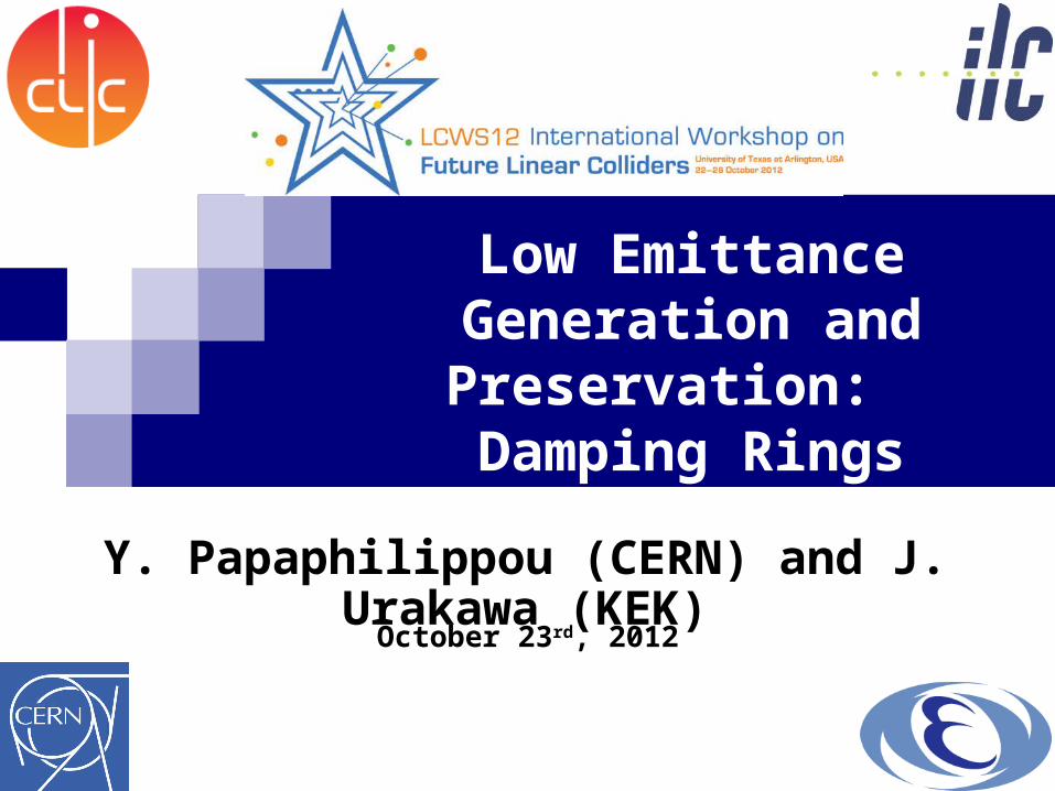
Emittance Preservation in ILC Damping RingProblems come from electron cloud and fast ion instability.Regarding with bunch-by-bunch extraction, we have to make a careful beam optical matching and a smooth impedance design. This issue was already confirmed by ATF extraction beam tuning (10pm, not 2pm. )
Wiggler RF Phase Trombone
Chicane Extraction
Injection
ILC Damping Ring Layout
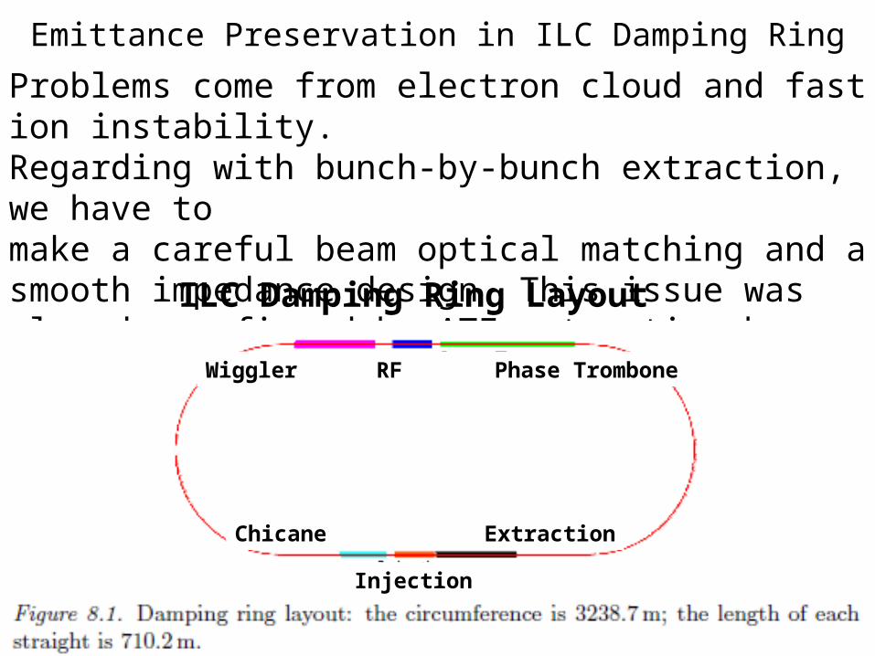
DTC lattice parameters for 5 Hz Low Power (baseline) and High Luminosity (upgrade) operating modes and 10 Hz repetition rate
(baseline) operationThree ILC operating modes correspond to four DR configurations, Two utilize a5 Hz repetition rate: low power baseline (1312 bunches/ring); and high luminosity upgrade (2625 bunches. Third operating mode is at 10 Hzand e- linac operated with alternatingpulses: high energy for e+ production followed by low energy for collisions. Shorter damping times in necessary to achieve the same extractedvertical emittance in half the nominal storage time
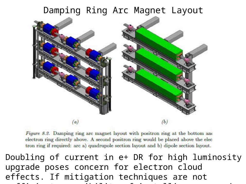
Damping Ring Arc Magnet Layout
Doubling of current in e+ DR for high luminosity upgrade poses concern for electron cloud effects. If mitigation techniques are not sufficient, possibility of installing a second e+ ring in the same tunnel.
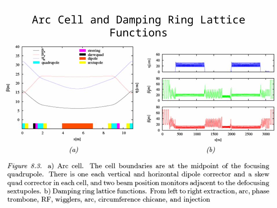
Arc Cell and Damping Ring Lattice Functions
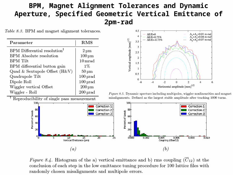
BPM, Magnet Alignment Tolerances and Dynamic Aperture, Specified Geometric Vertical Emittance of 2pm-rad
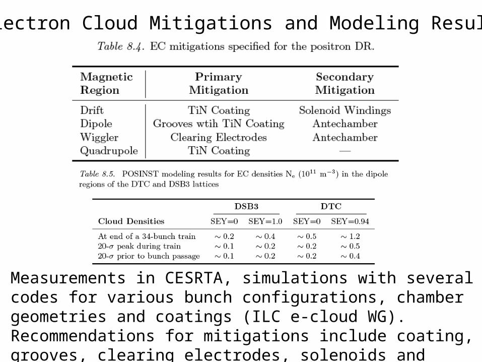
Electron Cloud Mitigations and Modeling Results
Measurements in CESRTA, simulations with several codes for various bunch configurations, chamber geometries and coatings (ILC e-cloud WG). Recommendations for mitigations include coating, grooves, clearing electrodes, solenoids and antechambers
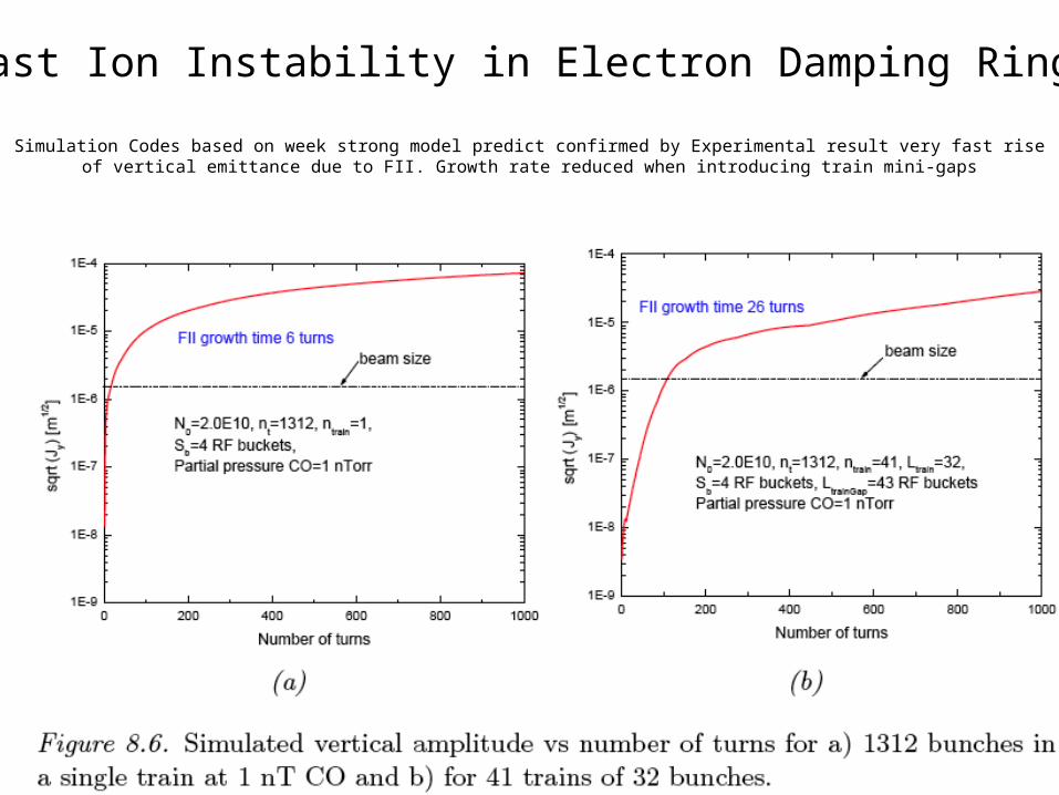
Simulation Codes based on week strong model predict confirmed by Experimental result very fast rise of vertical emittance due to FII. Growth rate reduced when introducing train mini-gaps
Fast Ion Instability in Electron Damping Ring
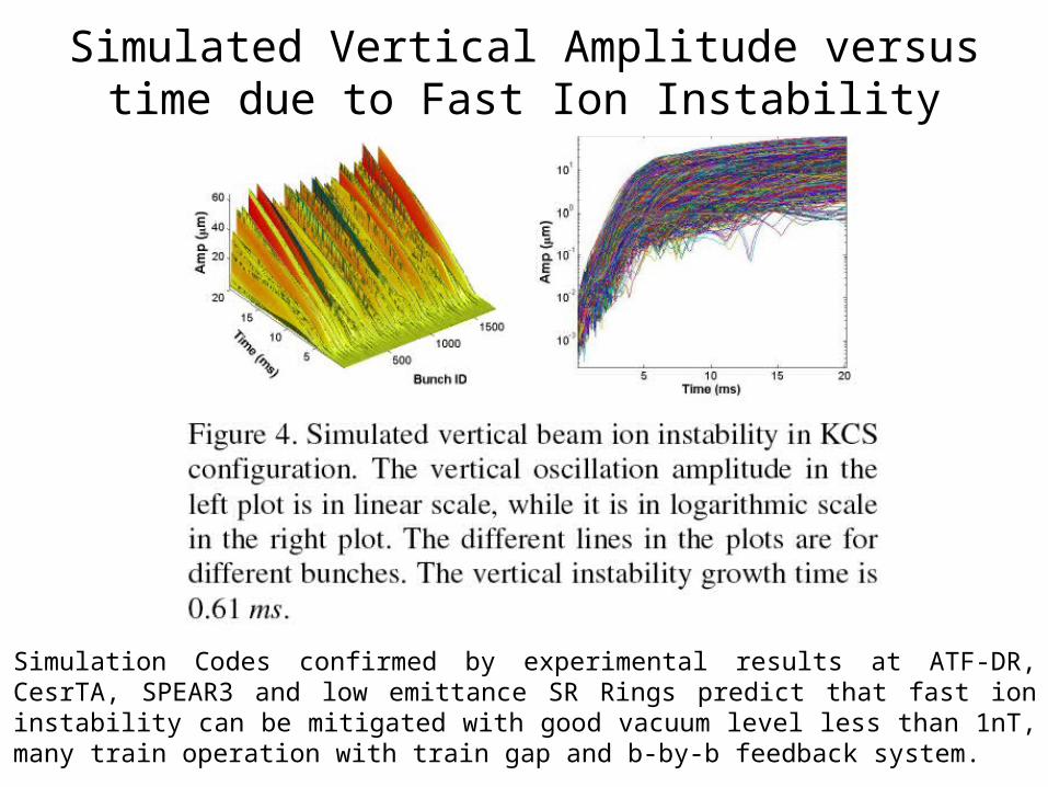
Simulated Vertical Amplitude versus time due to Fast Ion Instability
Simulation Codes confirmed by experimental results at ATF-DR, CesrTA, SPEAR3 and low emittance SR Rings predict that fast ion instability can be mitigated with good vacuum level less than 1nT, many train operation with train gap and b-by-b feedback system.
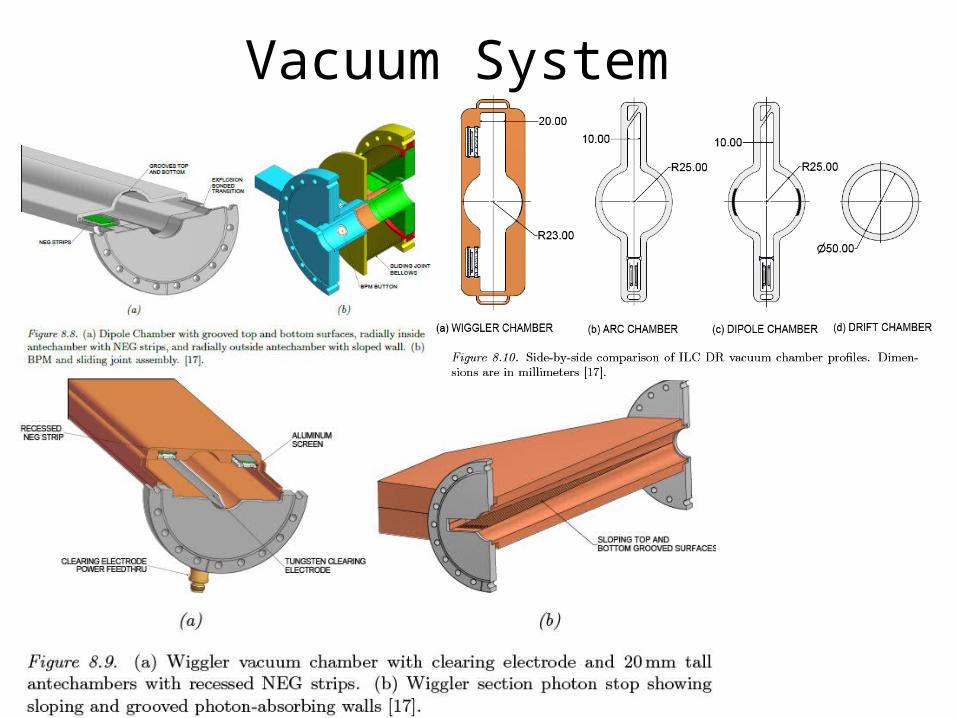
Vacuum System
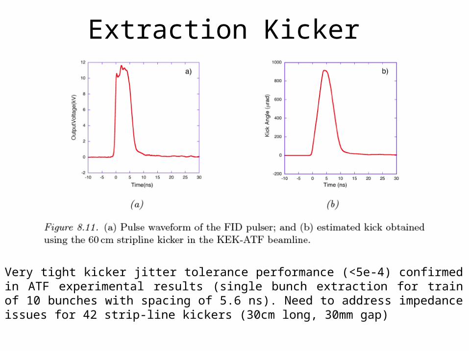
Extraction Kicker
Very tight kicker jitter tolerance performance (<5e-4) confirmed in ATF experimental results (single bunch extraction for train of 10 bunches with spacing of 5.6 ns). Need to address impedance issues for 42 strip-line kickers (30cm long, 30mm gap)
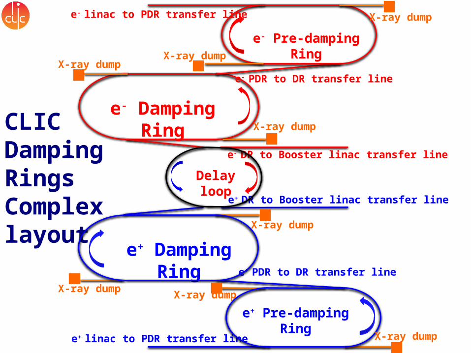
CLIC Damping Rings Complex layout
e+ Damping Ring
e- Damping Ring
e+ linac to PDR transfer line
e- linac to PDR transfer line
e+ PDR to DR transfer line
e+ DR to Booster linac transfer line
e- PDR to DR transfer line
e- DR to Booster linac transfer line
e- Pre-damping Ring
e+ Pre-damping Ring
X-ray dump
X-ray dump
X-ray dump
X-ray dump
X-ray dumpX-ray dump
X-ray dump
X-ray dump
Delay loop
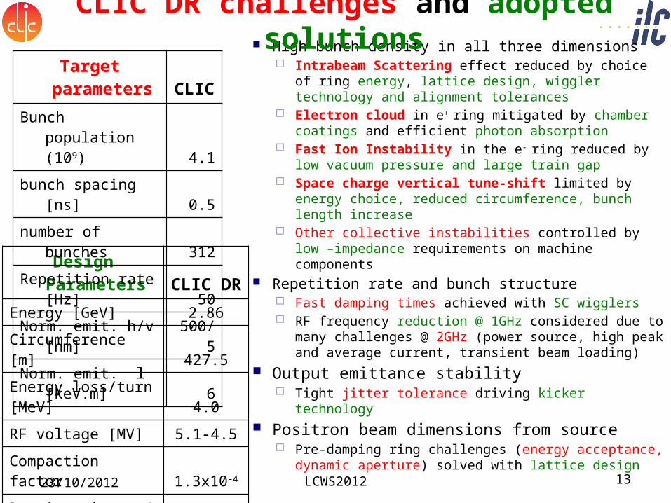
High-bunch density in all three dimensions Intrabeam Scattering effect reduced by choice
of ring energy, lattice design, wiggler technology and alignment tolerances
Electron cloud in e+ ring mitigated by chamber coatings and efficient photon absorption
Fast Ion Instability in the e- ring reduced by low vacuum pressure and large train gap
Space charge vertical tune-shift limited by energy choice, reduced circumference, bunch length increase
Other collective instabilities controlled by low –impedance requirements on machine components
Repetition rate and bunch structure Fast damping times achieved with SC wigglers RF frequency reduction @ 1GHz considered due
to many challenges @ 2GHz (power source, high peak and average current, transient beam loading)
Output emittance stability Tight jitter tolerance driving kicker technology
Positron beam dimensions from source Pre-damping ring challenges (energy acceptance,
dynamic aperture) solved with lattice design
Design Parameters CLIC DR
Energy [GeV] 2.86
Circumference [m] 427.5
Energy loss/turn [MeV] 4.0
RF voltage [MV] 5.1-4.5
Compaction factor 1.3x10⁻⁴
Damping time x / s [ms] 2.0/1.0
No bends / wigglers 100/52
Dipole/ wiggler field [T] 1.0/2.5
CLIC DR challenges and adopted solutions
Target parameters CLIC
Bunch population (109) 4.1
bunch spacing [ns] 0.5
number of bunches 312
Repetition rate [Hz] 50
Norm. emit. h/v [nm] 500/5
Norm. emit. l [keV.m] 6
23/10/2012 LCWS2012 13
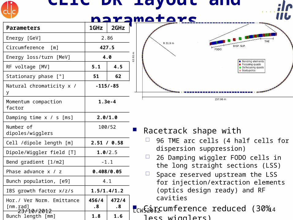
CLIC DR layout and parameters
Racetrack shape with 96 TME arc cells (4 half cells for
dispersion suppression) 26 Damping wiggler FODO cells in the
long straight sections (LSS) Space reserved upstream the LSS for
injection/extraction elements (optics design ready) and RF cavities
Circumference reduced (30% less wigglers)
Parameters 1GHz 2GHz
Energy [GeV] 2.86
Circumference [m] 427.5
Energy loss/turn [MeV] 4.0
RF voltage [MV] 5.1 4.5
Stationary phase [°] 51 62
Natural chromaticity x / y -115/-85
Momentum compaction factor 1.3e-4
Damping time x / s [ms] 2.0/1.0
Number of dipoles/wigglers 100/52
Cell /dipole length [m] 2.51 / 0.58
Dipole/Wiggler field [T] 1.0/2.5
Bend gradient [1/m2] -1.1
Phase advance x / z 0.408/0.05
Bunch population, [e9] 4.1
IBS growth factor x/z/s 1.5/1.4/1.2
Hor./ Ver Norm. Emittance [nm.rad]
456/4.8
472/4.8
Bunch length [mm] 1.8 1.6
Longitudinal emittance [keVm] 6.0 5.3
Space charge tune shift -0.10 -0.11
23/10/2012 LCWS2012 14
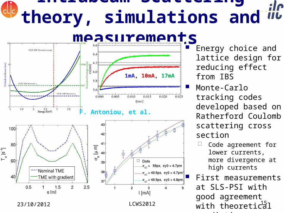
Intrabeam Scattering theory, simulations and
measurements Energy choice and
lattice design for reducing effect from IBS
Monte-Carlo tracking codes developed based on Ratherford Coulomb scattering cross section Code agreement for
lower currents, more divergence at high currents
First measurements at SLS-PSI with good agreement with theoretical predictions
23/10/2012
F. Antoniou, et al.
1mA, 10mA, 17mA
LCWS2012 15
Other collective effects Space-charge reduced <0.1 with combined
circumference reduction and bunch length increase
e-cloud in the e+ DR imposes limits in PEY (99.9%) and SEY (<1.3) achieved with wiggler absorption scheme and chamber coatings (amorphous carbon)
Fast ion instability in e- DR constrains vacuum pressure to around 0.1nTorr (large train gap also helps)
Single bunch instabilities avoided with smooth vacuum chamber design Simulations for instability thresholds for resistive
wall Resistive wall coupled bunch controlled with
feedback Conceptual design of 1-2GHz b-b-b feedback by T.
Nakamura (SPring8) Impedance estimates for effect of multiple
material layers Coherent synchrotron radiation estimates do
not
E. Koukovini-Platia, G. Rumolo, et al.
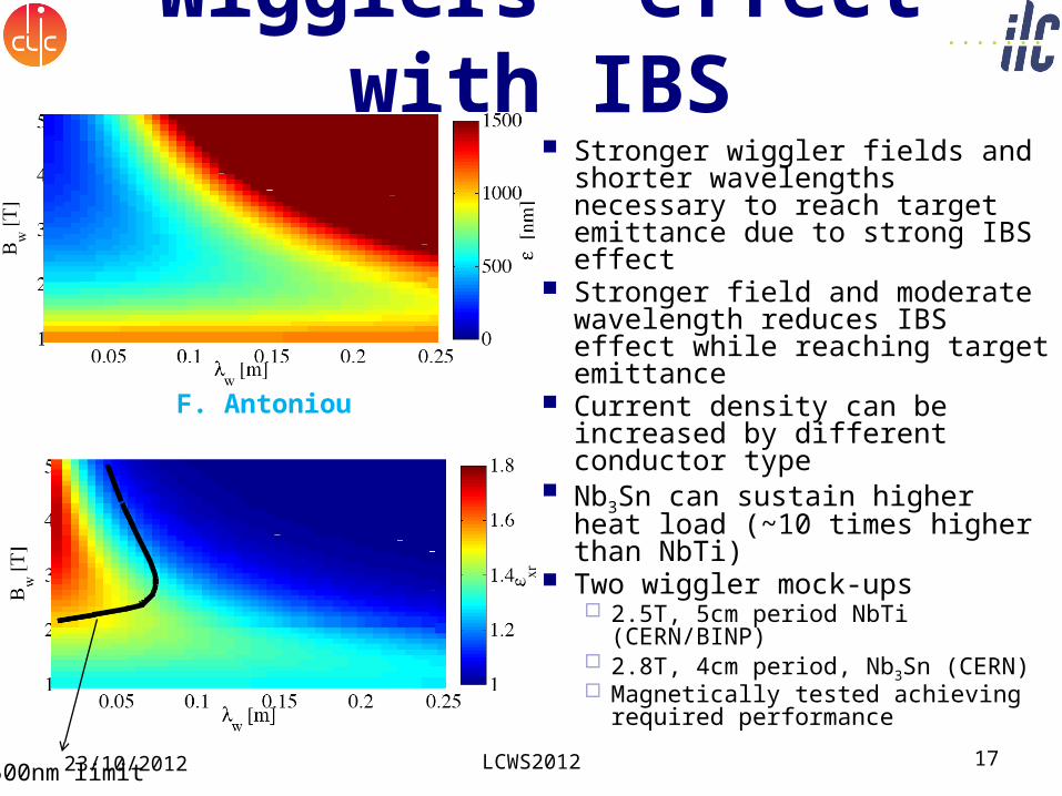
Wigglers’ effect with IBS
Stronger wiggler fields and shorter wavelengths necessary to reach target emittance due to strong IBS effect
Stronger field and moderate wavelength reduces IBS effect while reaching target emittance
Current density can be increased by different conductor type
Nb3Sn can sustain higher heat load (~10 times higher than NbTi)
Two wiggler mock-ups 2.5T, 5cm period NbTi
(CERN/BINP) 2.8T, 4cm period, Nb3Sn (CERN) Magnetically tested achieving
required performance
F. Antoniou
500nm limit23/10/2012 LCWS2012 17
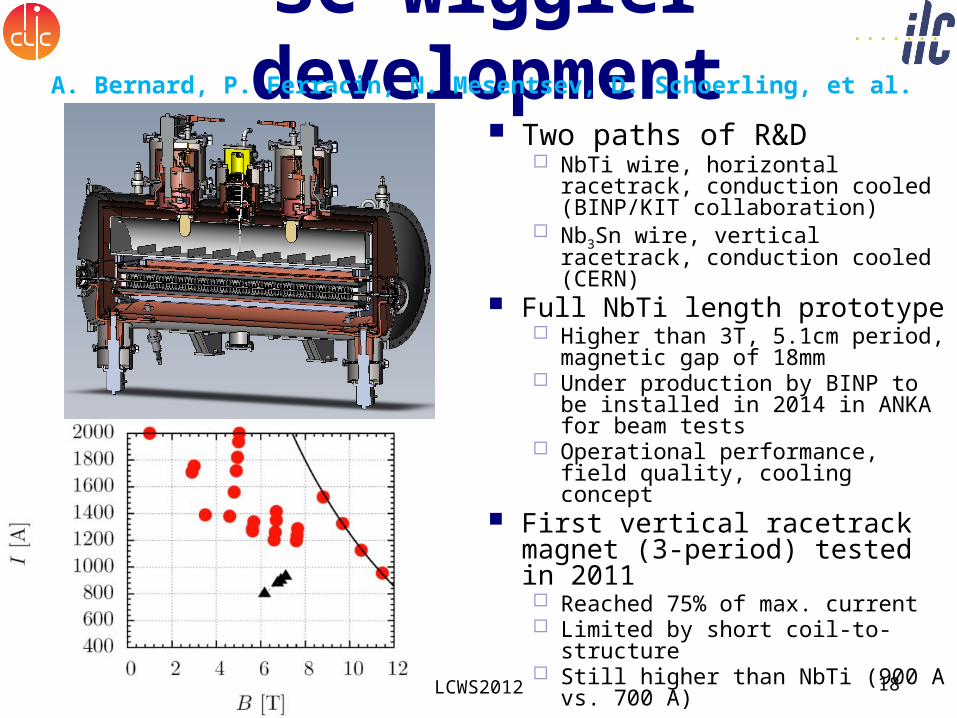
SC wiggler development
Two paths of R&D NbTi wire, horizontal
racetrack, conduction cooled (BINP/KIT collaboration)
Nb3Sn wire, vertical racetrack, conduction cooled (CERN)
Full NbTi length prototype Higher than 3T, 5.1cm period,
magnetic gap of 18mm Under production by BINP to
be installed in 2014 in ANKA for beam tests
Operational performance, field quality, cooling concept
First vertical racetrack magnet (3-period) tested in 2011 Reached 75% of max. current Limited by short coil-to-
structure Still higher than NbTi (900 A
vs. 700 A)
A. Bernard, P. Ferracin, N. Mesentsev, D. Schoerling, et al.
23/10/2012 LCWS2012 18
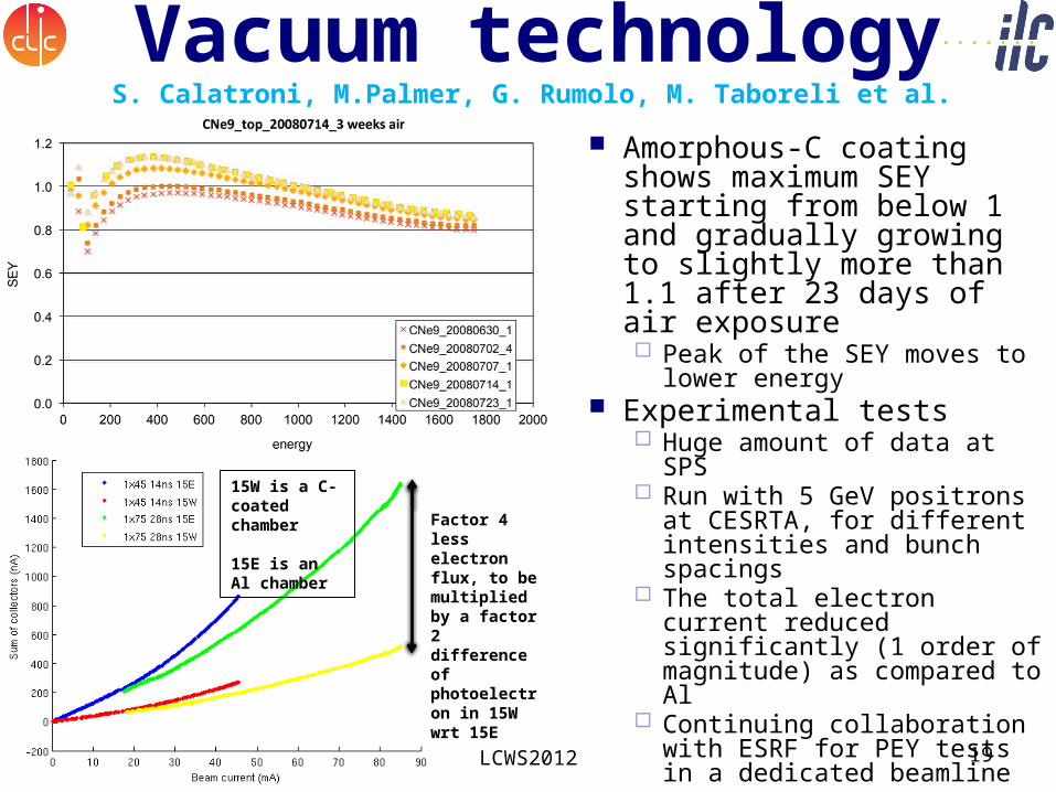
Vacuum technology Amorphous-C coating
shows maximum SEY starting from below 1 and gradually growing to slightly more than 1.1 after 23 days of air exposure Peak of the SEY moves to
lower energy Experimental tests
Huge amount of data at SPS
Run with 5 GeV positrons at CESRTA, for different intensities and bunch spacings
The total electron current reduced significantly (1 order of magnitude) as compared to Al
Continuing collaboration with ESRF for PEY tests in a dedicated beamline
S. Calatroni, M.Palmer, G. Rumolo, M. Taboreli et al.
23/10/2012 LCWS2012 19
Factor 4 less electron flux, to be multiplied by a factor 2 difference of photoelectron in 15W wrt 15E
15W is a C-coated chamber
15E is an Al chamber
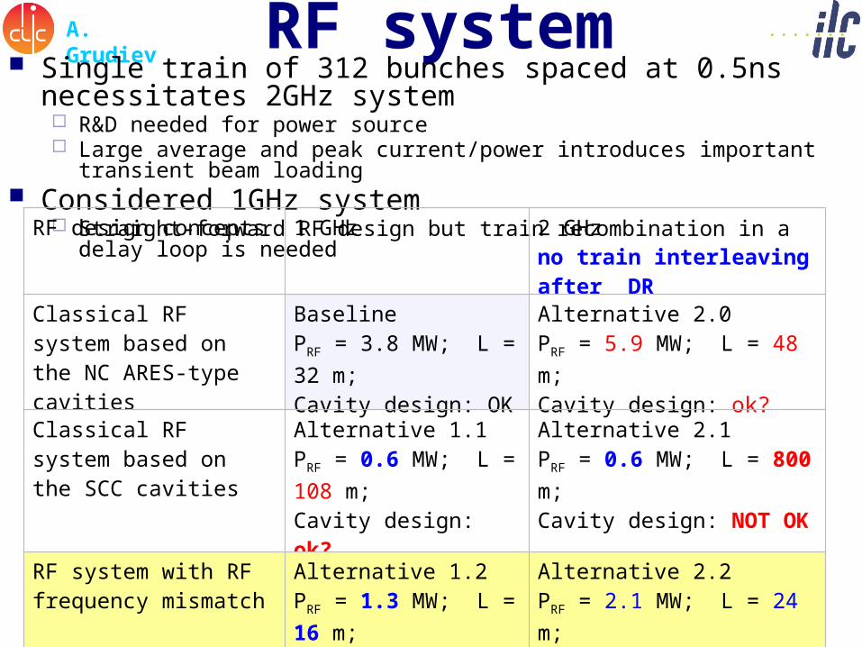
RF systemA. Grudiev Single train of 312 bunches spaced at 0.5ns
necessitates 2GHz system R&D needed for power source Large average and peak current/power introduces important
transient beam loading Considered 1GHz system
Straight-forward RF design but train recombination in a delay loop is needed
RF design concepts 1 GHz 2 GHzno train interleaving after DR
Classical RF system based on the NC ARES-type cavities
BaselinePRF = 3.8 MW; L = 32 m;Cavity design: OK
Alternative 2.0PRF = 5.9 MW; L = 48 m;Cavity design: ok?
Classical RF system based on the SCC cavities
Alternative 1.1PRF = 0.6 MW; L = 108 m;Cavity design: ok?
Alternative 2.1PRF = 0.6 MW; L = 800 m;Cavity design: NOT OK
RF system with RF frequency mismatch
Alternative 1.2PRF = 1.3 MW; L = 16 m;Cavity design: OK
Alternative 2.2PRF = 2.1 MW; L = 24 m;Cavity design: OK
“A-la-linac” RF system with strong input power modulations
Alternative 1.3PRF = 3.3 MW; L = 8 m;Cavity design: OK
Alternative 2.3PRF = 5.8 MW; L = 12 m;Cavity design: OK
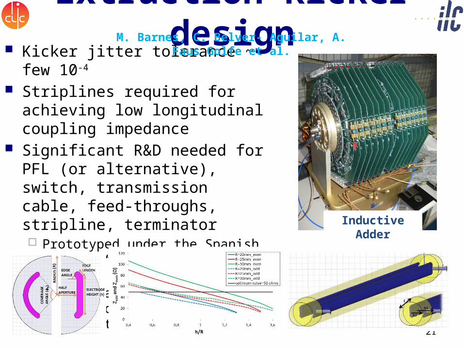
Extraction kicker design
Kicker jitter tolerance ~ few 10-4
Striplines required for achieving low longitudinal coupling impedance
Significant R&D needed for PFL (or alternative), switch, transmission cable, feed-throughs, stripline, terminator Prototyped under the Spanish
Program “Industry for Science” Collaboration is set-up with
ALBA synchrotron and ATF for beam tests
LCWS2012 2123/10/2012
M. Barnes, C. Belver- Aguilar, A. Faus Golfe et al.
Inductive Adder
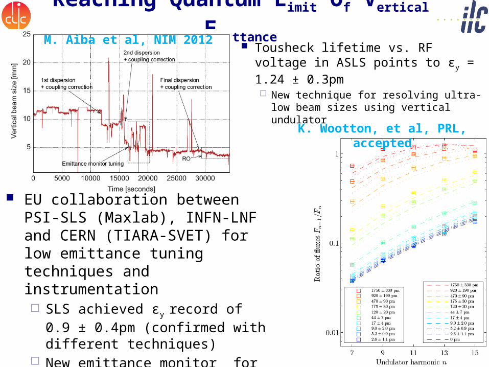
Reaching Quantum Limit Of Vertical Emittance
K. Wootton, et al, PRL, accepted
Tousheck lifetime vs. RF voltage in ASLS points to εy = 1.24 ± 0.3pm New technique for resolving ultra-low
beam sizes using vertical undulator
EU collaboration between PSI-SLS (Maxlab), INFN-LNF and CERN (TIARA-SVET) for low emittance tuning techniques and instrumentation SLS achieved εy record of 0.9 ±
0.4pm (confirmed with different techniques)
New emittance monitor for resolutions below 3μm (vertical polarized light) under installation for measurements in 2013
M. Aiba et al, NIM 2012
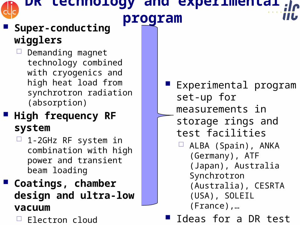
DR technology and experimental program
Super-conducting wigglers Demanding magnet
technology combined with cryogenics and high heat load from synchrotron radiation (absorption)
High frequency RF system 1-2GHz RF system in
combination with high power and transient beam loading
Coatings, chamber design and ultra-low vacuum Electron cloud
mitigation, low-impedance, fast-ion instability
Kicker technology Extracted beam stability
Diagnostics for low emittance Profile monitors,
feedback system
Experimental program set-up for measurements in storage rings and test facilities ALBA (Spain), ANKA
(Germany), ATF (Japan), Australia Synchrotron (Australia), CESRTA (USA), SOLEIL (France),…
Ideas for a DR test facility within a future LC test facility
Low Emittance Rings’ Collaboration Initiated by the ILC-CLIC
working group on damping rings and catalyzed by the organization of two workshops (01/2010 @ CERN, 10/2011 @ Heraklion) Common beam dynamics and
technology items for synchrotron light sources, linear collider damping rings, b-factories
Formed a EU network within EUCARD2 Coordinated by EU labs Extended collaboration board
including colleagues from US and Japan
30 participating institutes world wide
23/10/2012 24LCWS2012
Proposal approved with 330k€ allocated budget for 4 years starting 05/13
Recommended