7/31/2019 Low Cost Motion Capture
http://slidepdf.com/reader/full/low-cost-motion-capture 1/5
Low Cost Motion Capture
R. Budiman M. Bennamoun D.Q. Huynh
School of Computer Science and Software EngineeringThe University of Western Australia
Crawley WA 6009 AUSTRALIA
Email: [email protected], {bennamou,du}@csse.uwa.edu.au
Abstract
Traditionally, computer animation techniques were used to create movements of an object. Unfortunately,these techniques require much human intervention to work out the different joint angles for eachmovement. Not only is the task a very time-consuming one, the movements created are often notrealistic either. Modern motion capture techniques overcome those problems by capturing the actualmovements of a performer (e.g. human being) from the detected positions or angles of the sensors oroptical markers on the subject. Despite their advantages, motion capture has always been considered tobe an expensive technology. In this paper, we describe a low cost motion capture system that uses two
low cost webcams. We also demonstrate our experimental results of 3D reconstruction of the lower bodypart of a human subject.
Keywords: Motion capture, Mean-shift algorithm, Camera calibration, 3D reconstruction
1 Introduction
Motion capture, or mocap, is a technique of digitally recording the movements of real beings,usually humans or animals. Traditionally,computer animation techniques are used to createmovements of a being. However, this technique isproven to be time consuming and difficult. Motioncapture is considered to be a better technique foraccurately generating movements for computeranimation.
There are three types of motion capturetechniques [1]. The first technique is called theoptical motion capture in which photogrammetryis used to establish the position of an object in3D space based on its observed location withinthe 2D fields of a number of cameras. Thesecond technique is called the Magnetic motioncapture, where the position and orientation of
magnetic sensors are calculated with respectto a transmitter. The last technique is calledelectro-mechanical motion capture and it involvesmodelling movements using body suit with sensorsattached. The need for optical motion capturecan be justified by the fact that this techniqueis able to cover a large active area and, due tothe lightness in weight of the markers, providesmore freedom of movement for the subject.Despite these advantages, optical motion capturetechnologies have been known to be expensive.The high cost is mainly contributed by the cost of hardware components (i.e. high speed cameras).
In this paper, we describe the design and imple-mentation of a low cost optical motion capture sys-tem that requires two low cost calibrated webcams.This low cost system falls under the optical mo-tion capture category as advanced computer visiontechniques are employed to establish the joint po-sitions of a subject. As all motion capture systemsinvolve a tracking phase, we adopt the Mean-shiftalgorithm as the basis of object tracking. Whileour current system is constrained by several lim-itations such as the inability to handle occlusion,it is still able to demonstrate the fundamental ideaof motion capture and provides input to animationapplications, such as Poser [2].
The outline of this paper is as follows. In Section2, a brief overview of the Mean-shift algorithm willbe explained. In Section 3, the hardware compo-nents and the setup of our system will be described.Experiments and results are reported in Section 4.
Finally, conclusion and future work are given inSection 5.
2 Mean-shift: An overview
The mean-shift algorithm [3, 4, 5] is one of thetracking techniques commonly used in computervision research when the motion of the object tobe tracked cannot be described by a motion model,such as one required by the Kalman filter [6]. Thecolour and texture information that characterizesthe object can be grouped together to form thefeature vector in the tracking process. The algo-
7/31/2019 Low Cost Motion Capture
http://slidepdf.com/reader/full/low-cost-motion-capture 2/5
rithm requires only a small number of iterationsto converge and can easily adapt to the change of scale of the tracked object.
The key notion in the mean-shift algorithm is thedefinition of a multivariate density function with akernel function K (x) over a region in the image:
f (x) =1
nhd
ni=1
K
x− xi
h
,
where {xi | i = 1, · · · , n} is a set of points fallinginside a window of radius h centred at x. There area number of kernel functions that one can choosefrom. The commonly used ones are the Normal,Uniform, and Epanechnikov kernel functions. Ateach iteration the algorithm produces the mean-shift vector that describes the ‘movement’ of theregion that encloses the tracked target. As the
mean-shift vector is defined in terms of the neg-ative gradient of the kernel profile, a kernel func-tion that has the simplest profile gradient is pre-ferred. Amongst the commonly used kernel func-tion above, the Epanechnikov kernel, which hasits kernel profile as a uniform distribution, is pre-ferrable than the other two.
Comaniciu et al. [3, 4] formulate the target estima-tion problem as the derivation of the estimate thatmaximizes the Bayes error associated with the tar-get model and target candidate distributions. Thisapproach suggest that the larger is the probabilityof error, the more similar are the distributions.
Based on this assumption, the Bhattacharyya coef-ficient [7] is used to calculate the similarity measurebetween the two distributions.
3 System description
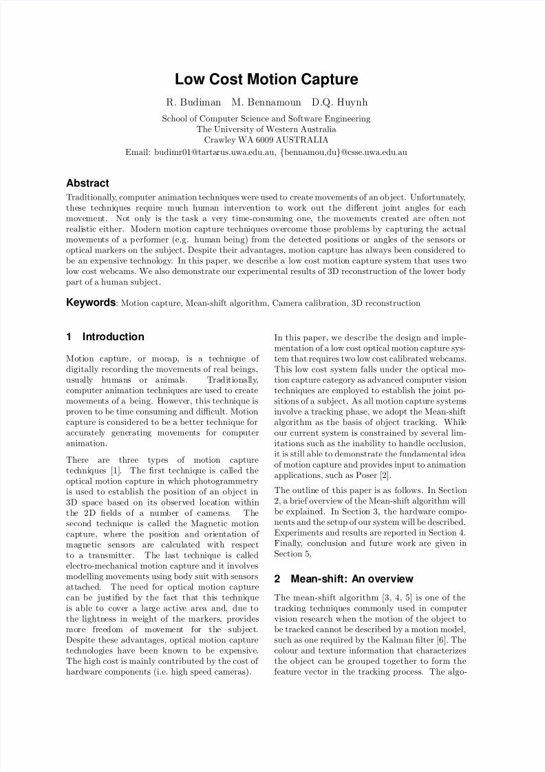
The setup of our motion capture system is intendedto be low-cost. The necessary pieces of equipmentrequired are two low-cost webcams, two tripods,and a calibration frame. The block diagram inFig. 1 shows all the components of the system.Each of these components will be described in de-tail later.
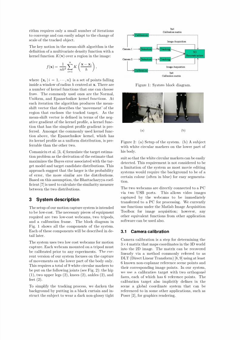
The system uses two low cost webcams for motioncapture. Each webcam mounted on a tripod mustbe calibrated prior to any experiments. The cur-rent version of our system focuses on the captureof movements on the lower part of the body only.This requires a total of 9 white circular markers tobe put on the following joints (see Fig. 2): the hip(1), two upper legs (2), knees (2), ankles (2), andfeet (2).
To simplify the tracking process, we darken thebackground by putting in a black curtain and in-struct the subject to wear a dark non-glossy tight
Figure 1: System block diagram.
(a) (b)
Figure 2: (a) Setup of the system. (b) A subjectwith white circular markers on the lower part of his body.
suit so that the white circular markers can be easilydetected. This requirement is not considered to bea limitation of the system as most movie editingsystems would require the background to be of a
certain colour (often in blue) for easy segmenta-tion.
The two webcams are directly connected to a PCvia two USB ports. This allows video imagescaptured by the webcams to be immediatelytransferred to a PC for processing. We currentlyuse functions under the Matlab Image AcquisitionToolbox for image acquisition; however, anyother equivalent functions from other applicationsoftware can be used also.
3.1 Camera calibration
Camera calibration is a step for determining the3×4 matrix that maps coordinates in the 3D worldinto the 2D image. The matrix can be recoveredlinearly via a method commonly referred to asDLT (Direct Linear Transform) [8, 9] using at least6 known non-coplanar reference scene points andtheir corresponding image points. In our system,we use a calibration target with two orthogonalfaces, each of which has 6 reference points. Thecalibration target also implicitly defines in thescene a global coordinate system that can bereferenced to in some other applications, such asPoser [2], for graphics rendering.
7/31/2019 Low Cost Motion Capture
http://slidepdf.com/reader/full/low-cost-motion-capture 3/5
Without moving the calibration target, each web-cam was calibrated in turn. The calibration pro-cess produces two 3 × 4 matrices, one for eachwebcam.
3.2 Detection of markers
The nine markers were detected via a thresholdingprocess. This thresholding process involves choos-ing a threshold value t from the pixel intensityrange of 0 to 255. Using a specific threshold valuet, the system converts all intensity values withina gray scale image that are greater than t into1 and all intensity values less than t into 0, andhence produces a binary image. Since we havea much simplified scene for marker detection, wecan inspect the intensity histogram to automati-cally compute the threshold value. As expected,our intensity histogram is bi-modal. Consecutive
frequency values in the intensity histogram can beexamined to determine the flat region that sepa-rates the two modes. The threshold value can thenbe estimated from the flat region in the intensityvalue histogram.
3.3 Automatic labellings of markers
The 9 markers are automatically labelled using aheuristic method. At the start of each experiment,the subject must adopt the standing pose positionas show in Fig. 3. After all nine markers have been
detected, the system labels the top middle markeras marker #1. The initial standing pose showsthat there are four markers on each leg. Hence,the four markers that are positioned to the left of marker #1 are labelled as marker #2 to #5 andthe four markers to the right of marker #1 arelabelled as marker #6 to #9. The assignment of marker number depends on the y component of themarker coordinates. So, for the four markers on theleft side, marker #2 is given to the marker whichhas the smallest y value compared to those of theother three markers. The same labelling algorithmis applied to the four markers to the right side of
marker #1.
3.4 Mean-shift tracking and 3D recon-struction of markers
The mean-shift algorithm is employed to track thenine white markers independently. The systemsetup described above allows the tracking to bedone on grey level images rather than colour. Thefeature that we used for tracking is therefore simplythe pixels’ intensity values and the density functionis the intensity histogram inside the kernel window.Note that, as defined by the Epanechnikov kernel
function, the weighting factors for points near thecentre of the kernel are higher, the intensity his-togram is computed with these different weightingfactors incorporated.
There are 3 free parameters that can be set to fine-tune the performance of the mean-shift algorithm:
1. The radius, h, of the kernel window.
2. The threshold value, , which is used for ter-minating the tracking iteration between con-secutive images.
3. The number of histogram bins, 1 < m < 255,for storing the frequencies of pixels’ intensityvalues inside the kernel window.
We will describe in the following section what val-ues these parameters were set to in our experi-
ments.For the computation of the 3D coordinates of eachmarker, the two 3 × 4 matrices obtained above arecombined to give 4 linear equations for the detectedimage coordinates of the marker in the two images.The 3D coordinates of each marker, relative to theimplicit global coordinate system defined by thecalibration frame, can be estimated using least-squares.
4 Results
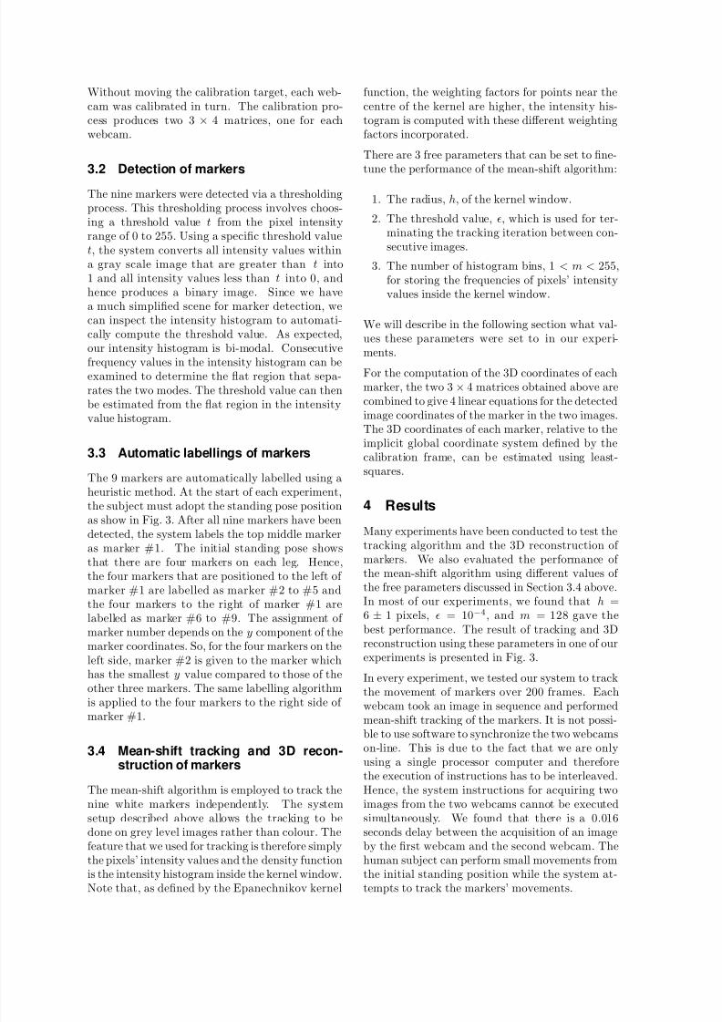
Many experiments have been conducted to test thetracking algorithm and the 3D reconstruction of markers. We also evaluated the performance of the mean-shift algorithm using different values of the free parameters discussed in Section 3.4 above.In most of our experiments, we found that h =6 ± 1 pixels, = 10−4, and m = 128 gave thebest performance. The result of tracking and 3Dreconstruction using these parameters in one of ourexperiments is presented in Fig. 3.
In every experiment, we tested our system to trackthe movement of markers over 200 frames. Eachwebcam took an image in sequence and performed
mean-shift tracking of the markers. It is not possi-ble to use software to synchronize the two webcamson-line. This is due to the fact that we are onlyusing a single processor computer and thereforethe execution of instructions has to be interleaved.Hence, the system instructions for acquiring twoimages from the two webcams cannot be executedsimultaneously. We found that there is a 0.016seconds delay between the acquisition of an imageby the first webcam and the second webcam. Thehuman subject can perform small movements fromthe initial standing position while the system at-tempts to track the markers’ movements.
7/31/2019 Low Cost Motion Capture
http://slidepdf.com/reader/full/low-cost-motion-capture 4/5
(a) seq. 1 (b) seq. 2
(c) front view (d) side view
Figure 3: (a) and (b) show the tracking results of the mean-shift algorithm on the 9 white markersusing a h value of 6 pixels; (c) and (d) the resultof reconstruction.
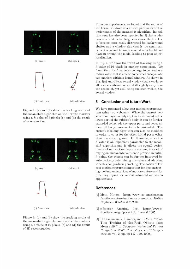
(a) seq. 1 (b) seq. 2
(c) front view (d) side view
Figure 4: (a) and (b) show the tracking results of the mean-shift algorithm on the 9 white markersusing a h value of 10 pixels. (c) and (d) the resultof 3D reconstruction.
From our experiments, we found that the radius of the kernel windows is a crucial parameter to theperformance of the mean-shift algorithm. Indeed,this issue has also been reported in [5] that a win-dow size that is too large can cause the trackerto become more easily distracted by background
clutter and a window size that is too small cancause the kernel to roam around on a likelihoodplateau around the mode, leading to poor objectlocalization.
In Fig. 4, we show the result of tracking using ah value of 10 pixels in another experiment. Wefound that this h value is too large to be used as aradius value as it is able to sometimes encapsulatetwo markers within a kernel window. As shown inFig. 4(a) and 4(b), a kernel window that is too largeallows the white markers to drift slightly away fromthe centre of, yet still being enclosed within, thekernel window.
5 Conclusion and future Work
We have presented a low cost motion capture sys-tem using two webcams. While the current ver-sion of our system only captures movement of thelower part of the subject’s body, it can be furtherextended to include the upper part, and hence al-lows full body movements to be animated. Thecurrent labelling algorithm can also be modifiedin order to cater for the other initial poses otherthan the standing one. Furthermore, since the
h value is an important parameter to the mean-shift algorithm and it affects the overall perfor-mance of our motion capture system, instead of relying on human intervention to provide an initialh value, the system can be further improved byautomatically determining this value and adaptingto scale changes during tracking. The notion of lowcost motion capture is important for demonstrat-ing the fundamental idea of motion capture and forproviding inputs for various advanced animationapplications.
References[1] Meta Motion, http://www.metamotion.com
/motion-capture/motion-capture.htm, Motion
Capture - What is it ? , 2004.
[2] e-frontier America, Inc, http://www.e-frontier.com/go/poser hpl, Poser 6 , 2005.
[3] D. Comaniciu, V. Ramesh, and P. Meer, “Real-Time Tracking of Non-Rigid Objects usingMean Shift,” in Computer Vision and Pattern
Recognition, 2000. Proceedings. IEEE Confer-
ence on , vol. 2, pp. pp 142–149, 2000.
7/31/2019 Low Cost Motion Capture
http://slidepdf.com/reader/full/low-cost-motion-capture 5/5
[4] D. Comaniciu and P. Meer, “Mean Shft Anal-ysis and Applications,” in Computer Vision,
1999. The Proceedings of the Seventh IEEE
International Conference on , vol. 2, pp. pp1197–1203, 1999.
[5] R. T. Collins, “Mean-Shift Blob Trackingthrough Scale Space,” in Computer Vision and
Pattern Recognition, 2003. Proceedings. 2003
IEEE Computer Society Conference on , vol. 2,pp. pp 18–20, 2003.
[6] G. Welch and G. Bishop, “An Introductionto the Kalman Filter,” Tech. Rep. 95-041,Department of Computer Science, Universityof North Carolina, Chapel Hill, 1995.
[7] T. Kailath, “The Divergence and Bhat-tacharyya Distance Measures in Signal Se-lection,” IEEE Trans. on Communications,
vol. 15, pp. 52–60, Feb 1967.
[8] Y. I. Abdel-Aziz and H. M. Karara, “DirectLinear Transformation from Comparator toObject Space Coordinates in Close-Range Pho-togrammetry,” in ASP Symposium on Close-
Range Photogrammetry (H. Karara, ed.), (Ur-bana, Illinois), pp. 1–18, 1971.
[9] C. C. Slama, C. Theurer, and S. W. Henrik-sen, eds., Manual of Photogrammetry . FallsChurch, Virginia, USA: American Society of Photogrammetry and Remote Sensing, 1980.
Recommended