Siemens LV 1 · 2009
17SENTRON Switching and Protection Devices – Switch Disconnectors, 8US Busbar Systems
17/2 Introduction
3KA, 3KE, 3LD Switch Disconnectors
3KA, 3KE Switch Disconnectors
up to 1000 A
17/5 General data
17/6 Floor mounting
17/11 Molded-plastic enclosures
17/12 Accessories
3LD Main Control and EMERGENCY-
STOP Switches up to 125 A
17/15 General data
17/16 Front mounting
17/21 Floor mounting
17/27 Distribution board mounting
17/29 Molded-plastic enclosures
17/31 Accessories
3KL, 3KM, 3NJ6 Switch Disconnectors with Fuses
3KL Switch Disconnectors with Fuses
up to 800 A
17/35 General data
17/36 Surface mounting and installation
17/38 Front mounting
17/39 Accessories
3KM Switch Disconnectors with Fuses
and Isolating Plug Connectors
up to 400 A
17/43 General data
17/44 For snapping onto busbars
17/45 Accessories
8UC Door-Coupling Rotary
Operating Mechanisms
17/47 For 3K switch disconnectors
17/52 Individual parts
17/53 Operating mechanisms for fixed
mounting
3NJ6 In-Line Switch Disconnectors with
Fuses up to 630 A
17/54 3NJ62 switch disconnectors with fuses
17/54 - Introduction
17/56 - For LV HRC fuse links
3NP, 3NJ4, 3NJ5 Fuse Switch Disconnectors
3NP Fuse Switch Disconnectors
up to 630 A
17/70 General data
17/71 3NP4 for power distribution
17/74 - With fuse monitoring
17/77 - Accessories
17/80 - Assembly kits for distribution
boards
17/83 3NP5 for extended technical requirements
17/85 - With fuse monitoring
17/89 - Accessories
17/92 - Assembly kits for distribution
boards
3NJ4, 3NJ5 In-Line Fuse Switch
Disconnectors up to 1250 A
17/93 General data
17/95 1-pole switchable
17/96 3-pole switchable
17/97 Accessories
SENTRON 8US Busbar Systems
17/102 General data
40 mm Busbar Systems
17/104 General data
17/105 Base assemblies
17/106 Infeed and connection components
17/107 Busbar adapters and device holders
17/111 Accessories
60 mm Busbar Systems
17/112 General data
17/113 Base assemblies up to 630 A
17/116 Base assemblies up to 1600 A
17/117 Infeed and connection components
17/119 Busbar adapters and device holders
17/124 Bus-mounting fuse bases
17/125 Accessories
© Siemens AG 2009
SENTRON Switch Disconnectors, 8US Busbar Systems
Introduction
17/2 Siemens LV 1 · 2009
17
n Overview
3 Available
-- Not available
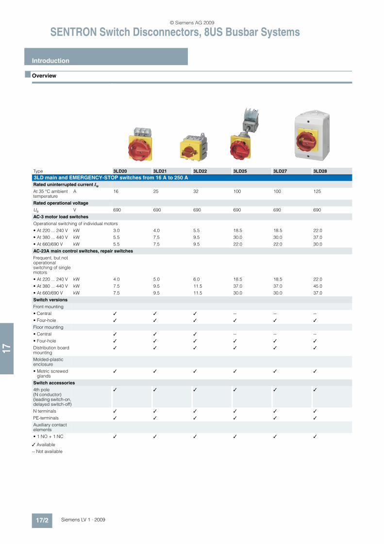
Type 3LD20 3LD21 3LD22 3LD25 3LD27 3LD28
3LD main and EMERGENCY-STOP switches from 16 A to 250 A
Rated uninterrupted current Iu
At 35 °C ambient temperature
A 16 25 32 100 100 125
Rated operational voltage
Ue V 690 690 690 690 690 690
AC-3 motor load switches
Operational switching of individual motors
• At 220 ... 240 V kW 3.0 4.0 5.5 18.5 18.5 22.0
• At 380 ... 440 V kW 5.5 7.5 9.5 30.0 30.0 37.0
• At 660/690 V kW 5.5 7.5 9.5 22.0 22.0 30.0
AC-23A main control switches, repair switches
Frequent, but not operational switching of single motors
• At 220 ... 240 V kW 4.0 5.0 6.0 18.5 18.5 22.0
• At 380 ... 440 V kW 7.5 9.5 11.5 37.0 37.0 45.0
• At 660/690 V kW 7.5 9.5 11.5 30.0 30.0 37.0
Switch versions
Front mounting
• Central 3 3 3 -- -- --
• Four-hole 3 3 3 3 3 3
Floor mounting
• Central 3 3 3 -- -- --
• Four-hole 3 3 3 3 3 3
Distribution board mounting
3 3 3 3 3 3
Molded-plastic enclosure
• Metric screwed glands
3 3 3 3 3 3
Switch accessories
4th pole (N conductor) (leading switch-on, delayed switch-off)
3 3 3 3 3 3
N terminals 3 3 3 3 3 3
PE-terminals 3 3 3 3 3 3
Auxiliary contact elements
• 1 NO + 1 NC 3 3 3 3 3 3
© Siemens AG 2009
17
SENTRON Switch Disconnectors, 8US Busbar Systems
Introduction
17/3Siemens LV 1 · 2009
3 Available
-- Not available
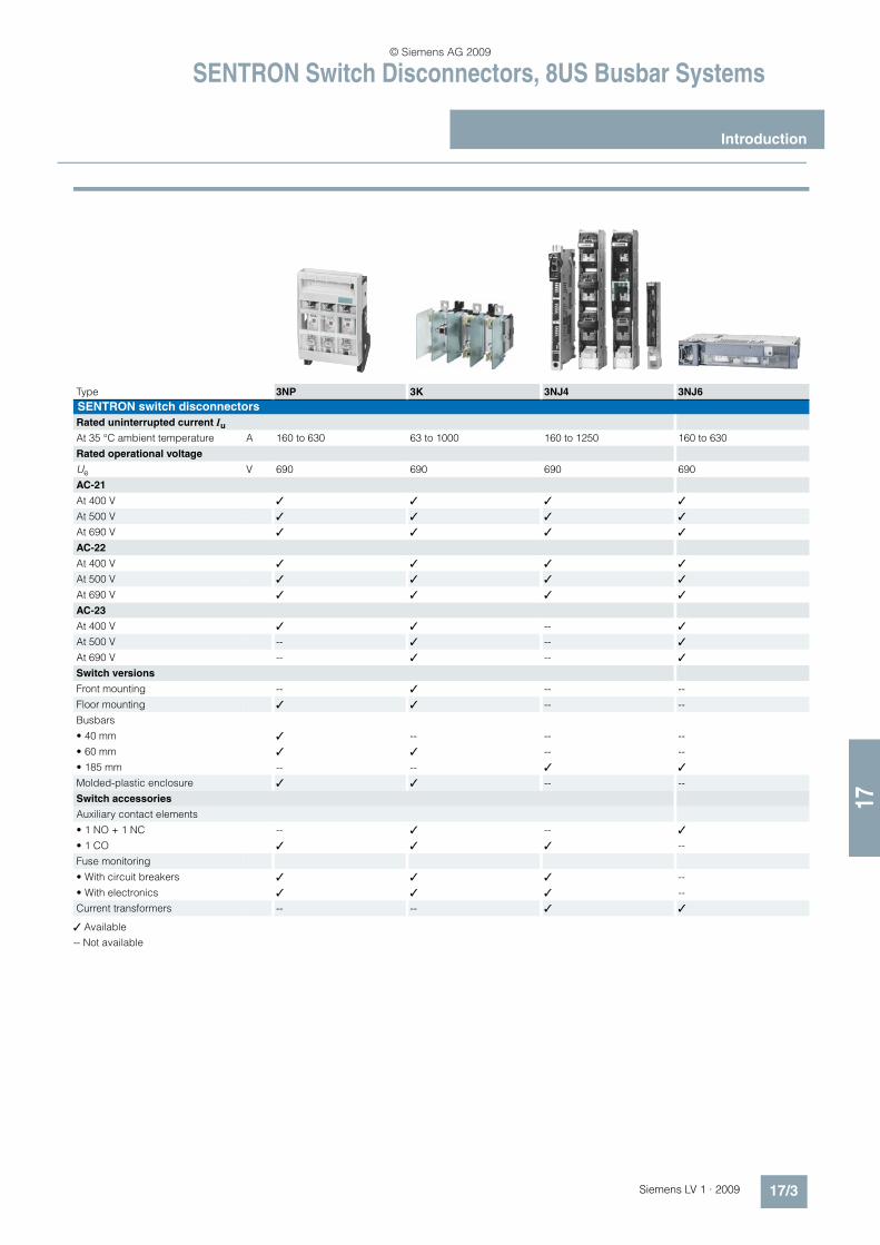
Type 3NP 3K 3NJ4 3NJ6
SENTRON switch disconnectors
Rated uninterrupted current Iu
At 35 °C ambient temperature A 160 to 630 63 to 1000 160 to 1250 160 to 630
Rated operational voltage
Ue V 690 690 690 690
AC-21
At 400 V 3 3 3 3
At 500 V 3 3 3 3
At 690 V 3 3 3 3
AC-22
At 400 V 3 3 3 3
At 500 V 3 3 3 3
At 690 V 3 3 3 3
AC-23
At 400 V 3 3 -- 3
At 500 V -- 3 -- 3
At 690 V -- 3 -- 3
Switch versions
Front mounting -- 3 -- --
Floor mounting 3 3 -- --
Busbars
• 40 mm 3 -- -- --
• 60 mm 3 3 -- --
• 185 mm -- -- 3 3
Molded-plastic enclosure 3 3 -- --
Switch accessories
Auxiliary contact elements
• 1 NO + 1 NC -- 3 -- 3
• 1 CO 3 3 3 --
Fuse monitoring
• With circuit breakers 3 3 3 --
• With electronics 3 3 3 --
Current transformers -- -- 3 3
© Siemens AG 2009
SENTRON Switch Disconnectors, 8US Busbar Systems
Introduction
17/4 Siemens LV 1 · 2009
17
3 Standard
-- Not available
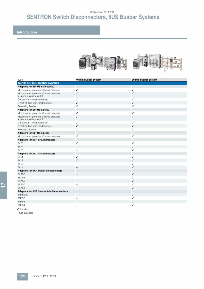
Type 40 mm busbar system 60 mm busbar system
SENTRON 8US busbar systems
Adapters for SIRIUS size S00/S0
Motor starter protectors/circuit breakers 3 3
Motor starter protectors/circuit breakers + lateral auxiliary switch
3 3
Contactors + overload relay 3 3
Direct-on-line start load feeders 3 3
Reversing feeder 3 3
Adapters for SIRIUS size S2
Motor starter protectors/circuit breakers 3 3
Motor starter protectors/circuit breakers + lateral auxiliary switch
3 3
Contactors + overload relay 3 3
Direct-on-line start load feeders 3 3
Reversing feeder 3 3
Adapters for SIRIUS size S3
Motor starter protectors/circuit breakers 3 3
Adapters for 3VF circuit breakers
3VF3 3 3
3VF4 -- 3
3VF5 -- 3
Adapters for 3VL circuit breakers
3VL1 3 3
3VL2 3 3
3VL3 -- 3
3VL4 -- 3
Adapters for 3KA switch disconnectors
3KA52 -- 3
3KA53 -- 3
3KA55 -- 3
3KA57 -- 3
3KA58 -- 3
Adapters for 3NP fuse switch disconnectors
3NP50 60 -- 3
3NP52 -- 3
3NP53 -- 3
3NP54 -- 3
© Siemens AG 2009
3KA, 3KE, 3LD Switch Disconnectors3KA, 3KE Switch Disconnectors up to 1000 A
General data
17/5Siemens LV 1 · 2009
17
n Overview
n Application
3KA and 3KE switch disconnectors are used as main control, EMERGENCY-STOP, maintenance and transfer switches in dis-tribution boards for residential and non-residential buildings as well as industrial switchboards. As three and four-pole versions, they ensure activation and deactivation of the specified rated current under load. At the same time, they constitute a safety iso-lating function and isolating distance in all low-voltage circuits.
All 3K switch disconnectors are climate-proof and meet the re-quirements of IEC 60947-1, IEC 60947-3 and VDE 0660 Part 107.
Switch disconnectors in the type-tested 8HP molded-plastic dis-tribution board enclosure (degree of protection IP65) are avail-able for use as safety switches.
More data can be found in the catalog "ALPHA Distribution Boards and Terminal Blocks" (Order No. E86060-K8210-A101-A8-7600).
2
3
4
5
6
7
1
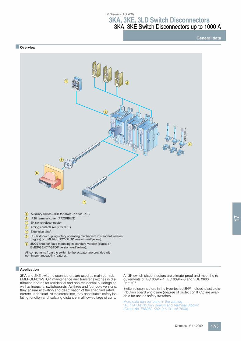
All components from the switch to the actuator are provided with non-interchangeability features.
IP20 terminal cover (PROFIBUS)
1
2
3 3K switch disconnector
4 Arcing contacts (only for 3KE)
5 Extension shaft
6
7 8UC9 knob for fixed mounting in standard version (black) or
EMERGENCY-STOP version (red/yellow).
8UC7 door-coupling rotary operating mechanism in standard version (ti-grey) or EMERGENCY-STOP version (red/yellow).
Auxiliary switch (3SB for 3KA; 3KX for 3KE)
NSE0_01931a
© Siemens AG 2009
3KA, 3KE, 3LD Switch Disconnectors3KA, 3KE Switch Disconnectors up to 1000 A
Floor mounting
17/6 Siemens LV 1 · 2009* You can order this quantity or a multiple thereof.
17
n Application
3KA switch disconnectors are implemented as main control switches and EMERGENCY-STOP switches for normal switching duty and isolation of main circuits and auxiliary circuits. Another field of application is the switching of induction motors and other loads in the event of maintenance and repair.
Main control and EMERGENCY-STOP switches are manually op-erated switch disconnectors according to IEC 60947-3 and EN 60947-3 (VDE 0660 Part 107) and comply with the condi-tions for switch disconnectors and the requirements of the ma-chinery directive EN 60204-1.
n Selection and ordering data
All switch disconnectors with degree of protection IP00Conductor connecting screws are generally included in the scope of supply
1) Rated values reduced in the event of strong harmonics caused by fre-quency converter operation.
For 8UC7 EMERGENCY-STOP door-coupling rotary operating mechanisms (red handle, yellow indicator plate), seeAccessories.
Rated uninterrupted current Iu DT Order No. Price per PU
PU (UNIT, SET, M)
PS* PG Weight per PU approx.
A kg
Complete versions with 8UC7 door-coupling rotary operating mechanism (black handle)
3-pole for motor loads and for power distribution
63 B 3KA50 30-1GE01 1 1 unit 103 1.44480 B 3KA51 30-1GE01 1 1 unit 103 1.403125 B 3KA52 30-1GE01 1 1 unit 103 2.383160 B 3KA53 30-1GE01 1 1 unit 103 2.426
250 B 3KA55 30-1GE01 1 1 unit 103 5.475400 B 3KA57 30-1GE01 1 1 unit 103 5.556630 B 3KA58 30-1GE01 1 1 unit 103 6.128
4-pole1) for power distribution
63 B 3KA50 40-1GE01 1 1 unit 103 2.49880 B 3KA51 40-1GE01 1 1 unit 103 2.540125 B 3KA52 40-1GE01 1 1 unit 103 2.490160 B 3KA53 40-1GE01 1 1 unit 103 2.458
250 B 3KA55 40-1GE01 1 1 unit 103 6.038400 B 3KA57 40-1GE01 1 1 unit 103 5.154630 B 3KA58 40-1GE01 1 1 unit 103 6.595
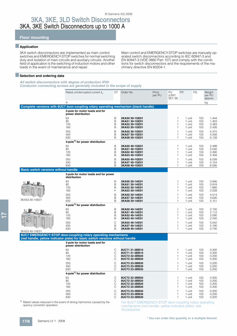
Basic switch versions without handle
3-pole for motor loads and for power distribution
3KA53 30-1AE01
63 B 3KA50 30-1AE01 1 1 unit 103 0.94680 B 3KA51 30-1AE01 1 1 unit 103 0.918125 B 3KA52 30-1AE01 1 1 unit 103 1.880160 } 3KA53 30-1AE01 1 1 unit 103 2.028
250 B 3KA55 30-1AE01 1 1 unit 103 4.514400 B 3KA57 30-1AE01 1 1 unit 103 4.630630 B 3KA58 30-1AE01 1 1 unit 103 5.151
4-pole1) for power distribution
3KA53 40-1AE01
63 B 3KA50 40-1AE01 1 1 unit 103 2.10080 B 3KA51 40-1AE01 1 1 unit 103 2.112125 B 3KA52 40-1AE01 1 1 unit 103 2.090160 B 3KA53 40-1AE01 1 1 unit 103 2.240
250 C 3KA55 40-1AE01 1 1 unit 103 5.042400 B 3KA57 40-1AE01 1 1 unit 103 5.195630 B 3KA58 40-1AE01 1 1 unit 103 5.740
8UC7 EMERGENCY-STOP door-coupling rotary operating mechanisms (red handle, yellow indicator plate) for basic switch versions without handle
3-pole for motor loads and for power distribution
63 C 8UC71 21-3BB10 1 1 unit 103 0.20080 C 8UC71 21-3BB10 1 1 unit 103 0.200125 C 8UC72 22-3BB20 1 1 unit 103 0.200160 C 8UC72 22-3BB20 1 1 unit 103 0.200
250 C 8UC73 23-3BB30 1 1 unit 103 0.200400 C 8UC73 23-3BB30 1 1 unit 103 0.200630 C 8UC73 23-3BB30 1 1 unit 103 0.200
4-pole1) for power distribution
63 C 8UC72 22-3BB20 1 1 unit 103 0.20080 C 8UC72 22-3BB20 1 1 unit 103 0.200125 C 8UC72 22-3BB20 1 1 unit 103 0.200160 C 8UC72 22-3BB20 1 1 unit 103 0.200
250 C 8UC73 23-3BB30 1 1 unit 103 0.200400 C 8UC73 23-3BB30 1 1 unit 103 0.200630 C 8UC73 23-3BB30 1 1 unit 103 0.200
© Siemens AG 2009
3KA, 3KE, 3LD Switch Disconnectors3KA, 3KE Switch Disconnectors up to 1000 A
Floor mounting
17/7Siemens LV 1 · 2009* You can order this quantity or a multiple thereof.
17
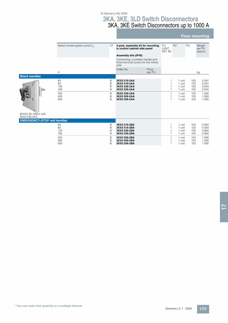
Rated uninterrupted current Iu DT 3-pole, assembly kit for mounting in control cabinet side panel
PU (UNIT, SET, M)
PS* PG Weight per PU approx.
Assembly kits (IP40)
Comprising: Lockable handle and three terminal covers for the infeed side
AOrder No. Price
per PU kg
Black handles
3KA53 30-1AE01 with 3KX3 536-2AA
63 B 3KX3 516-2AA 1 1 unit 103 0.59180 B 3KX3 516-2AA 1 1 unit 103 0.591125 B 3KX3 536-2AA 1 1 unit 103 0.843160 B 3KX3 536-2AA 1 1 unit 103 0.843
250 B 3KX3 556-2AA 1 1 unit 103 1.560400 B 3KX3 556-2AA 1 1 unit 103 1.560630 B 3KX3 556-2AA 1 1 unit 103 1.560
EMERGENCY-STOP red handles
63 B 3KX3 516-2BA 1 1 unit 103 0.58480 B 3KX3 516-2BA 1 1 unit 103 0.584125 B 3KX3 536-2BA 1 1 unit 103 0.860160 B 3KX3 536-2BA 1 1 unit 103 0.860
250 B 3KX3 556-2BA 1 1 unit 103 1.590400 B 3KX3 556-2BA 1 1 unit 103 1.590630 B 3KX3 556-2BA 1 1 unit 103 1.590
© Siemens AG 2009
3KA, 3KE, 3LD Switch Disconnectors3KA, 3KE Switch Disconnectors up to 1000 A
Floor mounting
17/8 Siemens LV 1 · 2009* You can order this quantity or a multiple thereof.
17
All switch disconnectors with degree of protection IP00with high speed closing and openingconductor connecting screws are generally included in the scope of supply
Rated uninterrupted current Iu DT 3-pole, operating mechanism and actuation from the front
PU (UNIT, SET, M)
PS* PG Weight per PU approx.
Direct operating mechanisms
AOrder No. Price
per PU kg
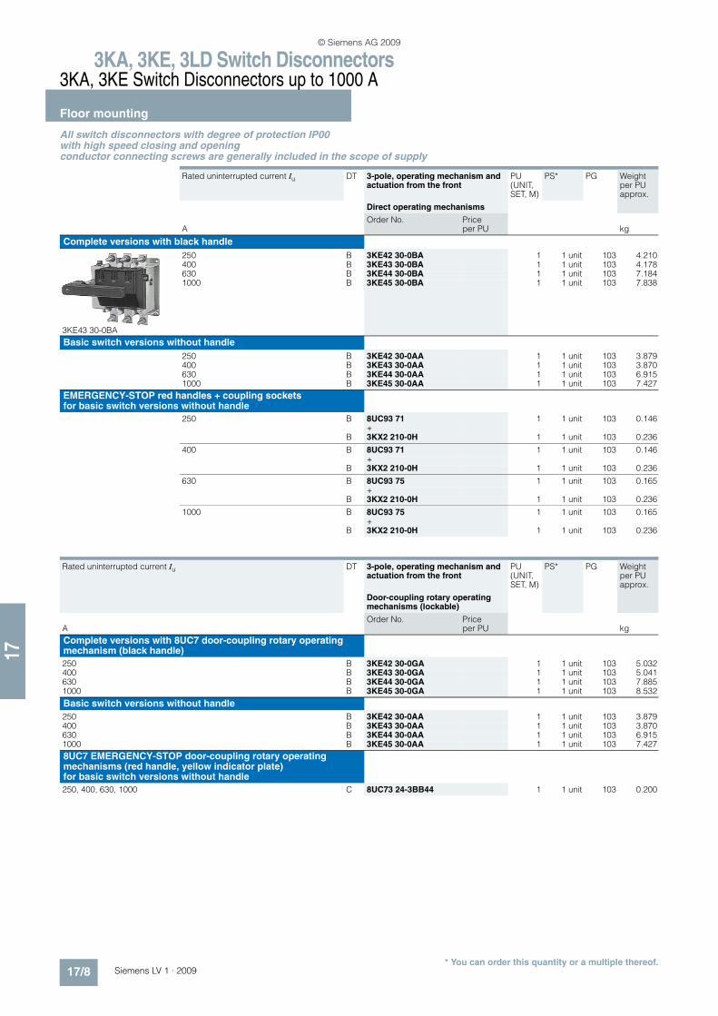
Complete versions with black handle
3KE43 30-0BA
250 B 3KE42 30-0BA 1 1 unit 103 4.210400 B 3KE43 30-0BA 1 1 unit 103 4.178630 B 3KE44 30-0BA 1 1 unit 103 7.1841000 B 3KE45 30-0BA 1 1 unit 103 7.838
Basic switch versions without handle
250 B 3KE42 30-0AA 1 1 unit 103 3.879400 B 3KE43 30-0AA 1 1 unit 103 3.870630 B 3KE44 30-0AA 1 1 unit 103 6.9151000 B 3KE45 30-0AA 1 1 unit 103 7.427
EMERGENCY-STOP red handles + coupling socketsfor basic switch versions without handle
250 B 8UC93 71 1 1 unit 103 0.146+
B 3KX2 210-0H 1 1 unit 103 0.236
400 B 8UC93 71 1 1 unit 103 0.146+
B 3KX2 210-0H 1 1 unit 103 0.236
630 B 8UC93 75 1 1 unit 103 0.165+
B 3KX2 210-0H 1 1 unit 103 0.236
1000 B 8UC93 75 1 1 unit 103 0.165+
B 3KX2 210-0H 1 1 unit 103 0.236
Rated uninterrupted current Iu DT 3-pole, operating mechanism and actuation from the front
PU (UNIT, SET, M)
PS* PG Weight per PU approx.
Door-coupling rotary operating mechanisms (lockable)
AOrder No. Price
per PU kg
Complete versions with 8UC7 door-coupling rotary operating mechanism (black handle)
250 B 3KE42 30-0GA 1 1 unit 103 5.032400 B 3KE43 30-0GA 1 1 unit 103 5.041630 B 3KE44 30-0GA 1 1 unit 103 7.8851000 B 3KE45 30-0GA 1 1 unit 103 8.532
Basic switch versions without handle
250 B 3KE42 30-0AA 1 1 unit 103 3.879400 B 3KE43 30-0AA 1 1 unit 103 3.870630 B 3KE44 30-0AA 1 1 unit 103 6.9151000 B 3KE45 30-0AA 1 1 unit 103 7.427
8UC7 EMERGENCY-STOP door-coupling rotary operating mechanisms (red handle, yellow indicator plate) for basic switch versions without handle
250, 400, 630, 1000 C 8UC73 24-3BB44 1 1 unit 103 0.200
© Siemens AG 2009
3KA, 3KE, 3LD Switch Disconnectors3KA, 3KE Switch Disconnectors up to 1000 A
Floor mounting
17/9Siemens LV 1 · 2009* You can order this quantity or a multiple thereof.
17
Rated uninterrupted current Iu DT 3-pole, rear operating mechanism and actuation
PU (UNIT, SET, M)
PS* PG Weight per PU approx.
AOrder No. Price
per PU kg
Basic switch versions without handle
Direct operating mechanisms
250 B 3KE42 30-0CA 1 1 unit 103 5.306400 B 3KE43 30-0CA 1 1 unit 103 5.030630 C 3KE44 30-0CA 1 1 unit 103 7.3951000 C 3KE45 30-0CA 1 1 unit 103 7.990
Direct operating mechanisms (lockable)
250 B 3KE42 30-0CA 1 1 unit 103 5.306400 B 3KE43 30-0CA 1 1 unit 103 5.030630 C 3KE44 30-0CA 1 1 unit 103 7.3951000 C 3KE45 30-0CA 1 1 unit 103 7.990
Handles (black) + masking plates + display plates (silver) for basic switch versions without handle
Direct operating mechanisms
250 B 8UC93 70 1 1 unit 103 0.128+
A 8UB95 30 1 1 unit 103 0.028+
A 8UC96 31-0B 1 1 unit 103 0.011
400 B 8UC93 70 1 1 unit 103 0.128+
A 8UB95 30 1 1 unit 103 0.028+
A 8UC96 31-0B 1 1 unit 103 0.011
630 B 8UC93 74 1 1 unit 103 0.145+
A 8UB95 30 1 1 unit 103 0.028+
A 8UC96 31-0B 1 1 unit 103 0.011
1000 B 8UC93 74 1 1 unit 103 0.145+
A 8UB95 30 1 1 unit 103 0.028+
A 8UC96 31-0B 1 1 unit 103 0.011
Direct operating mechanisms (lockable)
250 B 8UC93 70 1 1 unit 103 0.128+
B 8UC95 63 1 1 unit 103 0.271+
A 8UC96 31-0B 1 1 unit 103 0.011
400 B 8UC93 70 1 1 unit 103 0.128+
B 8UC95 63 1 1 unit 103 0.271+
A 8UC96 31-0B 1 1 unit 103 0.011
630 B 8UC93 74 1 1 unit 103 0.145+
B 8UC95 63 1 1 unit 103 0.271+
A 8UC96 31-0B 1 1 unit 103 0.011
1000 B 8UC93 74 1 1 unit 103 0.145+
B 8UC95 63 1 1 unit 103 0.271+
A 8UC96 31-0B 1 1 unit 103 0.011
© Siemens AG 2009
3KA, 3KE, 3LD Switch Disconnectors3KA, 3KE Switch Disconnectors up to 1000 A
Floor mounting
17/10 Siemens LV 1 · 2009* You can order this quantity or a multiple thereof.
17
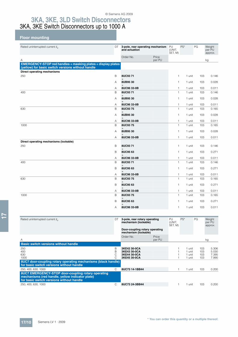
EMERGENCY-STOP red handles + masking plates + display plates (yellow) for basic switch versions without handle
Direct operating mechanisms
250 B 8UC93 71 1 1 unit 103 0.146+
A 8UB95 30 1 1 unit 103 0.028+
A 8UC96 33-0B 1 1 unit 103 0.011
400 B 8UC93 71 1 1 unit 103 0.146+
A 8UB95 30 1 1 unit 103 0.028+
A 8UC96 33-0B 1 1 unit 103 0.011
630 B 8UC93 75 1 1 unit 103 0.165+
A 8UB95 30 1 1 unit 103 0.028+
A 8UC96 33-0B 1 1 unit 103 0.011
1000 B 8UC93 75 1 1 unit 103 0.165+
A 8UB95 30 1 1 unit 103 0.028+
A 8UC96 33-0B 1 1 unit 103 0.011
Direct operating mechanisms (lockable)
250 B 8UC93 71 1 1 unit 103 0.146+
B 8UC95 63 1 1 unit 103 0.271+
A 8UC96 33-0B 1 1 unit 103 0.011
400 B 8UC93 71 1 1 unit 103 0.146+
B 8UC95 63 1 1 unit 103 0.271+
A 8UC96 33-0B 1 1 unit 103 0.011
630 B 8UC93 75 1 1 unit 103 0.165+
B 8UC95 63 1 1 unit 103 0.271+
A 8UC96 33-0B 1 1 unit 103 0.011
1000 B 8UC93 75 1 1 unit 103 0.165+
B 8UC95 63 1 1 unit 103 0.271+
A 8UC96 33-0B 1 1 unit 103 0.011
Rated uninterrupted current Iu DT 3-pole, rear operating mechanism and actuation
PU (UNIT, SET, M)
PS* PG Weight per PU approx.
AOrder No. Price
per PU kg
Rated uninterrupted current Iu DT 3-pole, rear rotary operating mechanism (lockable)
PU (UNIT, SET, M)
PS* PG Weight per PU approx.
Door-coupling rotary operating mechanism (lockable)
AOrder No. Price
per PU kg
Basic switch versions without handle
250 B 3KE42 30-0CA 1 1 unit 103 5.306400 B 3KE43 30-0CA 1 1 unit 103 5.030630 C 3KE44 30-0CA 1 1 unit 103 7.3951000 C 3KE45 30-0CA 1 1 unit 103 7.990
8UC7 door-coupling rotary operating mechanisms (black handle)for basic switch versions without handle
250, 400, 630, 1000 C 8UC73 14-1BB44 1 1 unit 103 0.200
8UC7 EMERGENCY-STOP door-coupling rotary operating mechanisms (red handle, yellow indicator plate) for basic switch versions without handle
250, 400, 630, 1000 C 8UC73 24-3BB44 1 1 unit 103 0.200
© Siemens AG 2009
3KA, 3KE, 3LD Switch Disconnectors3KA, 3KE Switch Disconnectors up to 1000 A
Molded-plastic enclosures
17/11Siemens LV 1 · 2009* You can order this quantity or a multiple thereof.
17
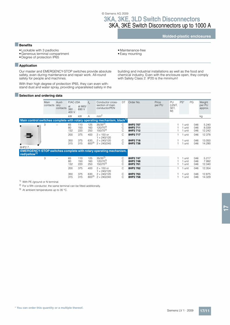
n Benefits
• Lockable with 3 padlocks• Generous terminal compartment• Degree of protection IP65
• Maintenance-free• Easy mounting
n Application
Our master and EMERGENCY-STOP switches provide absolute safety, even during maintenance and repair work. All-round safety for people and machines.
With their high degree of protection IP65, they can even with-stand dust and water spray, providing unparalleled safety in the
building and industrial installations as well as the food and chemical industry. Even with the enclosure open, they comply with Safety Class 2. IP20 is the minimum!
n Selection and ordering data
1) With PE-/ground or N terminal.2) For a fifth conductor, the same terminal can be fitted additionally.3) At ambient temperatures up to 35 °C.
Main contacts
Auxil-iary contacts
P/AC-23A Iu Conductor cross-section of main conductor/PEN
DT Order No. Price per PU
PU (UNIT, SET, M)
PS* PG Weight per PU approx.
at 380 ... 400 V
at 660/690 V
kW kW A mm2 kg
Main control switches complete with rotary operating mechanism, black1)
8HP2 7..
3 -- 65 110 125 35/352) C 8HP2 707 1 1 unit 046 5.24080 150 160 120/702) C 8HP2 711 1 1 unit 046 8.039132 220 250 150/702) C 8HP2 712 1 1 unit 046 12.242
200 375 400 2 × 150 or 1 × 240/120
C 8HP2 717 1 1 unit 046 12.378
350 375 630 2 × 240/120 C 8HP2 718 1 1 unit 046 13.050315 315 8003) 2 × 240/240 C 8HP2 738 1 1 unit 046 14.290
EMERGENCY-STOP switches complete with rotary operating mechanism, red/yellow1)
3 -- 65 110 125 35/352) C 8HP2 747 1 1 unit 046 5.21780 150 160 120/702) C 8HP2 748 1 1 unit 046 7.992132 220 250 150/702) C 8HP2 761 1 1 unit 046 12.340
200 375 400 2 × 150 or 1 × 240/120
C 8HP2 762 1 1 unit 046 12.354
350 375 630 2 × 240/120 C 8HP2 763 1 1 unit 046 12.875315 315 8003) 2 × 240/240 C 8HP2 758 1 1 unit 046 14.329
© Siemens AG 2009
3KA, 3KE, 3LD Switch Disconnectors3KA, 3KE Switch Disconnectors up to 1000 A
Accessories
17/12 Siemens LV 1 · 2009* You can order this quantity or a multiple thereof.
17
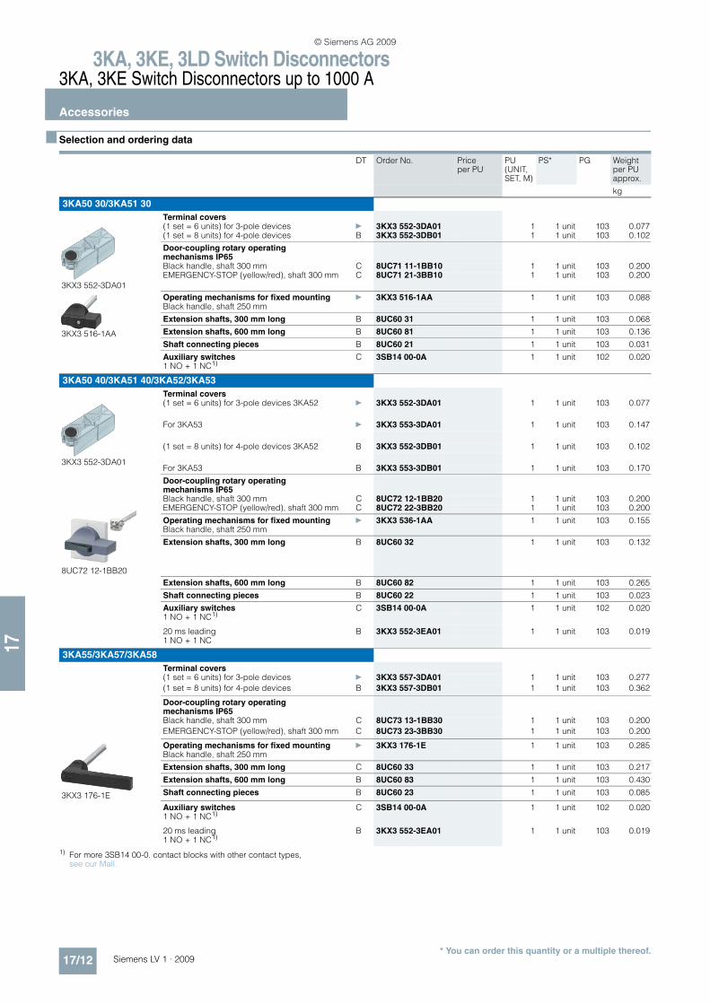
n Selection and ordering data
1) For more 3SB14 00-0. contact blocks with other contact types, see our Mall.
DT Order No. Price per PU
PU (UNIT, SET, M)
PS* PG Weight per PU approx.
kg
3KA50 30/3KA51 30
Terminal covers
3KX3 552-3DA01
(1 set = 6 units) for 3-pole devices } 3KX3 552-3DA01 1 1 unit 103 0.077(1 set = 8 units) for 4-pole devices B 3KX3 552-3DB01 1 1 unit 103 0.102
Door-coupling rotary operating mechanisms IP65Black handle, shaft 300 mm C 8UC71 11-1BB10 1 1 unit 103 0.200EMERGENCY-STOP (yellow/red), shaft 300 mm C 8UC71 21-3BB10 1 1 unit 103 0.200
3KX3 516-1AA
Operating mechanisms for fixed mounting } 3KX3 516-1AA 1 1 unit 103 0.088Black handle, shaft 250 mm
Extension shafts, 300 mm long B 8UC60 31 1 1 unit 103 0.068
Extension shafts, 600 mm long B 8UC60 81 1 1 unit 103 0.136
Shaft connecting pieces B 8UC60 21 1 1 unit 103 0.031
Auxiliary switches C 3SB14 00-0A 1 1 unit 102 0.0201 NO + 1 NC1)
3KA50 40/3KA51 40/3KA52/3KA53
Terminal covers
3KX3 552-3DA01
(1 set = 6 units) for 3-pole devices 3KA52 } 3KX3 552-3DA01 1 1 unit 103 0.077
For 3KA53 } 3KX3 553-3DA01 1 1 unit 103 0.147
(1 set = 8 units) for 4-pole devices 3KA52 B 3KX3 552-3DB01 1 1 unit 103 0.102
For 3KA53 B 3KX3 553-3DB01 1 1 unit 103 0.170
Door-coupling rotary operating mechanisms IP65
8UC72 12-1BB20
Black handle, shaft 300 mm C 8UC72 12-1BB20 1 1 unit 103 0.200EMERGENCY-STOP (yellow/red), shaft 300 mm C 8UC72 22-3BB20 1 1 unit 103 0.200
Operating mechanisms for fixed mounting } 3KX3 536-1AA 1 1 unit 103 0.155Black handle, shaft 250 mm
Extension shafts, 300 mm long B 8UC60 32 1 1 unit 103 0.132
Extension shafts, 600 mm long B 8UC60 82 1 1 unit 103 0.265
Shaft connecting pieces B 8UC60 22 1 1 unit 103 0.023
Auxiliary switches C 3SB14 00-0A 1 1 unit 102 0.0201 NO + 1 NC1)
20 ms leading B 3KX3 552-3EA01 1 1 unit 103 0.0191 NO + 1 NC
3KA55/3KA57/3KA58
Terminal covers(1 set = 6 units) for 3-pole devices } 3KX3 557-3DA01 1 1 unit 103 0.277
(1 set = 8 units) for 4-pole devices B 3KX3 557-3DB01 1 1 unit 103 0.362
Door-coupling rotary operating mechanisms IP65Black handle, shaft 300 mm C 8UC73 13-1BB30 1 1 unit 103 0.200
EMERGENCY-STOP (yellow/red), shaft 300 mm C 8UC73 23-3BB30 1 1 unit 103 0.200
3KX3 176-1E
Operating mechanisms for fixed mounting } 3KX3 176-1E 1 1 unit 103 0.285Black handle, shaft 250 mm
Extension shafts, 300 mm long C 8UC60 33 1 1 unit 103 0.217
Extension shafts, 600 mm long B 8UC60 83 1 1 unit 103 0.430
Shaft connecting pieces B 8UC60 23 1 1 unit 103 0.085
Auxiliary switches C 3SB14 00-0A 1 1 unit 102 0.0201 NO + 1 NC1)
20 ms leading B 3KX3 552-3EA01 1 1 unit 103 0.0191 NO + 1 NC1)
© Siemens AG 2009

3KA, 3KE, 3LD Switch Disconnectors3KA, 3KE Switch Disconnectors up to 1000 A
Accessories
17/13Siemens LV 1 · 2009* You can order this quantity or a multiple thereof.
17
Version DT Order No. Price per PU
PU (UNIT, SET, M)
PS* PG Weight per PU approx.
kg
3KE42/3KE43
Changeover switches
Changeover switches with interruption
3KX2 210-0D
Switch I ON – Switch II OFF B 3KX2 210-0D 1 1 unit 103 2.442Switch I OFF – Switch II ONSwitch I OFF – Switch II ON
Door-coupling rotary operating mechanisms IP65
C 8UC74 14-1BF44 1 1 unit 103 0.200
Twin handle (black), shaft 300 mm
Direct operating mechanisms B 8UC93 81 1 1 unit 103 0.264Twin handle (black) for fixed mounting
Changeover switches without interruptionSwitch I ON – Switch II OFF B 3KX2 210-0E 1 1 unit 103 2.448Switch I ON – Switch II ONSwitch I OFF – Switch II ON
Door-coupling rotary operating mechanisms IP65Twin handle (black), shaft 300 mm C 8UC74 14-1FG44 1 1 unit 103 0.200
Direct operating mechanisms B 8UC93 81 1 1 unit 103 0.264Twin handle (black) for fixed mounting
Parallel switches
Switch I ON – Switch II OFF C 3KX2 250-1A 1 1 unit 103 0.750
Switch I OFF – Switch II OFF
Door-coupling rotary operating mechanisms IP65
C 8UC74 14-1BB44 1 1 unit 103 0.200
Twin handle (black), shaft 300 mm
EMERGENCY-STOP door-coupling rotary operating mechanisms IP65
C 8UC74 24-3BB44 1 1 unit 103 0.200
Twin handle (red), shaft 300 mm
Direct operating mechanisms B 8UC93 81 1 1 unit 103 0.264Twin handle (black) for fixed mounting
Further accessories
3KX3 557-3DA01
Terminal covers } 3KX3 557-3DA01 1 1 unit 103 0.277(1 set = 6 units)
Door-coupling rotary operating mechanisms IP65Black handle, shaft 300 mm C 8UC73 14-1BB44 1 1 unit 103 0.200
EMERGENCY-STOP (yellow/red), shaft 300 mm
C 8UC73 24-3BB44 1 1 unit 103 0.200
Extension shafts, 300 mm long B 8UC60 34 1 1 unit 103 0.315
Extension shafts, 600 mm long B 8UC60 84 1 1 unit 103 0.640
3KX2 231-1A
Auxiliary switches with switching cam B 3KX2 231-1A 1 1 unit 103 0.0491 NO + 1 NC (complete mounting kit)
Grounding brackets B 3KX2 252-1A 1 1 unit 103 0.049
Arc chutes B 3KY2 202-0B 1 1 unit 103 0.640(spare part with 3 arc-splitter assemblies)
3KY2 204-0A
Arcing contacts B 3KY2 204-0A 1 1 unit 103 0.202(spare part with 3 fixed and 3 movable contact pieces)
© Siemens AG 2009

3KA, 3KE, 3LD Switch Disconnectors3KA, 3KE Switch Disconnectors up to 1000 A
Accessories
17/14 Siemens LV 1 · 2009* You can order this quantity or a multiple thereof.
17
Version DT Order No. Price per PU
PU (UNIT, SET, M)
PS* PG Weight per PU approx.
kg
3KE44/3KE45
3KX2 210-0D
Changeover switches
Changeover switches with interruptionSwitch I ON – Switch II OFF B 3KX2 210-0D 1 1 unit 103 2.442Switch I OFF – Switch II OFFSwitch I OFF – Switch II ON
Door-coupling rotary operating mechanisms IP65
C 8UC74 14-1BF44 1 1 unit 103 0.200
Twin handle (black), shaft 300 mm
Direct operating mechanisms B 8UC93 81 1 1 unit 103 0.264Twin handle (black) for fixed mounting
Changeover switches without interruptionSwitch I ON – Switch II OFF B 3KX2 210-0E 1 1 unit 103 2.448
Switch I ON – Switch II ON
Switch I OFF – Switch II ON
Door-coupling rotary operating mechanisms IP65
C 8UC74 14-1FG44 1 1 unit 103 0.200
Twin handle (black), shaft 300 mm
Direct operating mechanisms B 8UC93 81 1 1 unit 103 0.264Twin handle (black) for fixed mounting
Parallel switches
Switch I ON – Switch II OFF C 3KX2 250-1A 1 1 unit 103 0.750
Switch I OFF – Switch II OFF
Door-coupling rotary operating mechanisms IP65
C 8UC74 14-1BB44 1 1 unit 103 0.200
Twin handle (black), shaft 300 mm
EMERGENCY-STOP door-coupling rotary operating mechanisms IP65
C 8UC74 24-3BB44 1 1 unit 103 0.200
Twin handle (red), shaft 300 mm
Direct operating mechanisms B 8UC93 81 1 1 unit 103 0.264Twin handle (black) for fixed mounting
Further accessories
Terminal covers B 3KX2 252-0C 1 1 unit 103 0.424(top and bottom)
Door-coupling rotary operating mechanisms IP65Black handle, shaft 300 mm C 8UC73 14-1BB44 1 1 unit 103 0.200
3KX2 231-1A
EMERGENCY-STOP (yellow/red), square shaft 300 mm
C 8UC73 24-3BB44 1 1 unit 103 0.200
Extension shafts, 300 mm long B 8UC60 34 1 1 unit 103 0.315
Extension shafts, 600 mm long B 8UC60 84 1 1 unit 103 0.640
Auxiliary switches B 3KX2 231-1A 1 1 unit 103 0.0491 NO + 1 NC (complete mounting kit)
Grounding brackets B 3KX2 252-1A 1 1 unit 103 0.049
3KY2 232-0A
Arc chutes B 3KY2 232-0A 1 1 unit 103 1.040(spare part with 3 arc-splitter assemblies)
Arcing contacts B 3KY2 234-0A 1 1 unit 103 0.105(spare part with 3 fixed and 3 movable contact pieces)
© Siemens AG 2009
3KA, 3KE, 3LD Switch Disconnectors3LD Main Control and EMERGENCY-STOP Switches up to 125 A
General data
17/15Siemens LV 1 · 2009
17
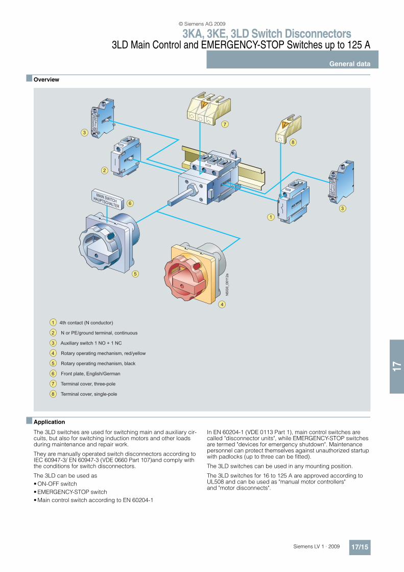
n Overview
n Application
The 3LD switches are used for switching main and auxiliary cir-cuits, but also for switching induction motors and other loads during maintenance and repair work.
They are manually operated switch disconnectors according to IEC 60947-3/ EN 60947-3 (VDE 0660 Part 107)and comply with the conditions for switch disconnectors.
The 3LD can be used as
• ON-OFF switch
• EMERGENCY-STOP switch
• Main control switch according to EN 60204-1
In EN 60204-1 (VDE 0113 Part 1), main control switches are called "disconnector units", while EMERGENCY-STOP switches are termed "devices for emergency shutdown". Maintenance personnel can protect themselves against unauthorized startup with padlocks (up to three can be fitted).
The 3LD switches can be used in any mounting position.
The 3LD switches for 16 to 125 A are approved according to UL508 and can be used as "manual motor controllers" and "motor disconnects".
4
7
6
5
3
2
1
NSG0_00112a
3
8
1 4th contact (N conductor)
2 N or PE/ground terminal, continuous
3 Auxiliary switch 1 NO + 1 NC
4 Rotary operating mechanism, red/yellow
5 Rotary operating mechanism, black
6 Front plate, English/German
7 Terminal cover, three-pole
8 Terminal cover, single-pole
© Siemens AG 2009
3KA, 3KE, 3LD Switch Disconnectors3LD Main Control and EMERGENCY-STOP Switches up to 125 A
Front mounting
17/16 Siemens LV 1 · 2009* You can order this quantity or a multiple thereof.
17
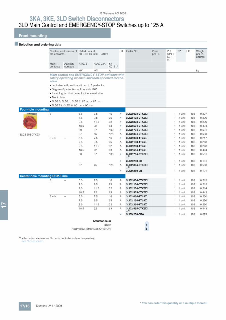
n Selection and ordering data
1) 4th contact element as N conductor to be ordered separately, see "Accessories".
Number and version of the contacts
Rated data at 50 ... 60 Hz 380 ... 440 V
DT Order No. Price per PU
PU (UNIT, SET, M)
PS* PG Weight per PU approx.
Main contacts
Auxiliary contacts
P/AC-3 P/AC-23A Iu/AC-21A
kW kW A kg
Main control and EMERGENCY-STOP switches with rotary operating mechanism/knob-operated mecha-nism
• Lockable in 0 position with up to 3 padlocks
• Degree of protection at front side IP65
• Including terminal cover for the infeed side
• Front plate
• 3LD2 0, 3LD2 1, 3LD2 2: 67 mm × 67 mm
• 3LD2 5 to 3LD2 8: 90 mm × 90 mm
Four-hole mounting
3LD2 203-0TK53
3 -- 5.5 7.5 16 } 3LD2 003-0TK5@ 1 1 unit 103 0.207
7.5 9.5 25 } 3LD2 103-0TK5@ 1 1 unit 103 0.206
9.5 11.5 32 } 3LD2 203-0TK5@ 1 1 unit 103 0.206
18.5 22 63 } 3LD2 504-0TK5@ 1 1 unit 103 0.424
30 37 100 } 3LD2 704-0TK5@ 1 1 unit 103 0.501
37 45 125 A 3LD2 804-0TK5@ 1 1 unit 103 0.503
3 + N -- 5.5 7.5 16 } 3LD2 003-1TL5@ 1 1 unit 103 0.217
7.5 9.5 25 A 3LD2 103-1TL5@ 1 1 unit 103 0.243
9.5 11.5 32 A 3LD2 203-1TL5@ 1 1 unit 103 0.243
18.5 22 63 A 3LD2 504-1TL5@ 1 1 unit 103 0.424
30 37 100 } 3LD2 704-0TK5@ 1 1 unit 103 0.501+1)
} 3LD9 280-0B 1 1 unit 103 0.101
37 45 125 A 3LD2 804-0TK5@ 1 1 unit 103 0.503+1)
} 3LD9 280-0B 1 1 unit 103 0.101
Center-hole mounting Ø 22.5 mm
3 -- 5.5 7.5 16 A 3LD2 054-0TK5@ 1 1 unit 103 0.215
7.5 9.5 25 A 3LD2 154-0TK5@ 1 1 unit 103 0.215
9.5 11.5 32 A 3LD2 254-0TK5@ 1 1 unit 103 0.214
18.5 22 63 A 3LD2 555-0TK5@ 1 1 unit 103 0.443
3 + N -- 5.5 7.5 16 A 3LD2 054-1TL5@ 1 1 unit 103 0.230
7.5 9.5 25 A 3LD2 154-1TL5@ 1 1 unit 103 0.256
9.5 11.5 32 A 3LD2 254-1TL5@ 1 1 unit 103 0.260
18.5 22 63 A 3LD2 555-0TK5@ 1 1 unit 103 0.443+1)
} 3LD9 250-0BA 1 1 unit 103 0.079
Actuator color>
Black 1
Red/yellow (EMERGENCY-STOP) 3
© Siemens AG 2009
3KA, 3KE, 3LD Switch Disconnectors3LD Main Control and EMERGENCY-STOP Switches up to 125 A
Front mounting
17/17Siemens LV 1 · 2009* You can order this quantity or a multiple thereof.
17
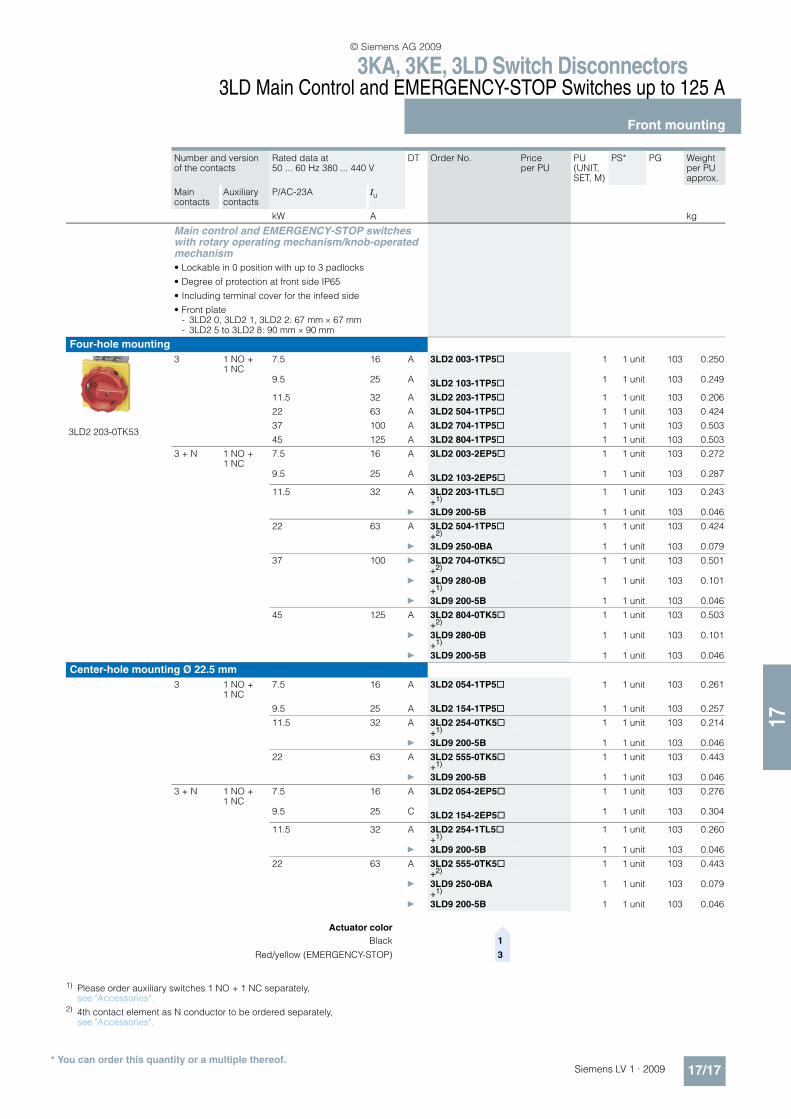
1) Please order auxiliary switches 1 NO + 1 NC separately, see "Accessories".
2) 4th contact element as N conductor to be ordered separately, see "Accessories".
Number and version of the contacts
Rated data at 50 ... 60 Hz 380 ... 440 V
DT Order No. Price per PU
PU (UNIT, SET, M)
PS* PG Weight per PU approx.
Main contacts
Auxiliary contacts
P/AC-23A Iu
kW A kg
Main control and EMERGENCY-STOP switches with rotary operating mechanism/knob-operated mechanism
• Lockable in 0 position with up to 3 padlocks
• Degree of protection at front side IP65
• Including terminal cover for the infeed side
• Front plate- 3LD2 0, 3LD2 1, 3LD2 2: 67 mm × 67 mm- 3LD2 5 to 3LD2 8: 90 mm × 90 mm
Four-hole mounting
3LD2 203-0TK53
3 1 NO + 1 NC
7.5 16 A 3LD2 003-1TP5@ 1 1 unit 103 0.250
9.5 25 A 3LD2 103-1TP5@ 1 1 unit 103 0.249
11.5 32 A 3LD2 203-1TP5@ 1 1 unit 103 0.206
22 63 A 3LD2 504-1TP5@ 1 1 unit 103 0.424
37 100 A 3LD2 704-1TP5@ 1 1 unit 103 0.503
45 125 A 3LD2 804-1TP5@ 1 1 unit 103 0.503
3 + N 1 NO + 1 NC
7.5 16 A 3LD2 003-2EP5@ 1 1 unit 103 0.272
9.5 25 A 3LD2 103-2EP5@ 1 1 unit 103 0.287
11.5 32 A 3LD2 203-1TL5@ 1 1 unit 103 0.243+1)
} 3LD9 200-5B 1 1 unit 103 0.046
22 63 A 3LD2 504-1TP5@ 1 1 unit 103 0.424+2)
} 3LD9 250-0BA 1 1 unit 103 0.079
37 100 } 3LD2 704-0TK5@ 1 1 unit 103 0.501+2)
} 3LD9 280-0B 1 1 unit 103 0.101+1)
} 3LD9 200-5B 1 1 unit 103 0.046
45 125 A 3LD2 804-0TK5@ 1 1 unit 103 0.503+2)
} 3LD9 280-0B 1 1 unit 103 0.101+1)
} 3LD9 200-5B 1 1 unit 103 0.046
Center-hole mounting Ø 22.5 mm
3 1 NO + 1 NC
7.5 16 A 3LD2 054-1TP5@ 1 1 unit 103 0.261
9.5 25 A 3LD2 154-1TP5@ 1 1 unit 103 0.257
11.5 32 A 3LD2 254-0TK5@ 1 1 unit 103 0.214+1)
} 3LD9 200-5B 1 1 unit 103 0.046
22 63 A 3LD2 555-0TK5@ 1 1 unit 103 0.443+1)
} 3LD9 200-5B 1 1 unit 103 0.046
3 + N 1 NO + 1 NC
7.5 16 A 3LD2 054-2EP5@ 1 1 unit 103 0.276
9.5 25 C 3LD2 154-2EP5@ 1 1 unit 103 0.304
11.5 32 A 3LD2 254-1TL5@ 1 1 unit 103 0.260+1)
} 3LD9 200-5B 1 1 unit 103 0.046
22 63 A 3LD2 555-0TK5@ 1 1 unit 103 0.443+2)
} 3LD9 250-0BA 1 1 unit 103 0.079+1)
} 3LD9 200-5B 1 1 unit 103 0.046
Actuator color>
Black 1
Red/yellow (EMERGENCY-STOP) 3
© Siemens AG 2009
3KA, 3KE, 3LD Switch Disconnectors3LD Main Control and EMERGENCY-STOP Switches up to 125 A
Front mounting
17/18 Siemens LV 1 · 2009* You can order this quantity or a multiple thereof.
17
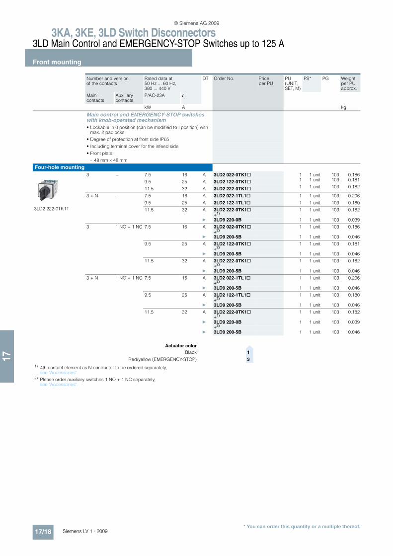
Number and version of the contacts
Rated data at 50 Hz ... 60 Hz, 380 ... 440 V
DT Order No. Price per PU
PU (UNIT, SET, M)
PS* PG Weight per PU approx.
Main contacts
Auxiliary contacts
P/AC-23A Iu
kW A kg
Main control and EMERGENCY-STOP switches with knob-operated mechanism
• Lockable in 0 position (can be modified to I position) with max. 2 padlocks
• Degree of protection at front side IP65
• Including terminal cover for the infeed side
• Front plate
- 48 mm × 48 mm
Four-hole mounting
3LD2 222-0TK11
3 -- 7.5 16 A 3LD2 022-0TK1@ 1 1 unit 103 0.186
9.5 25 A 3LD2 122-0TK1@ 1 1 unit 103 0.181
11.5 32 A 3LD2 222-0TK1@ 1 1 unit 103 0.182
3 + N -- 7.5 16 A 3LD2 022-1TL1@ 1 1 unit 103 0.206
9.5 25 A 3LD2 122-1TL1@ 1 1 unit 103 0.180
11.5 32 A 3LD2 222-0TK1@ 1 1 unit 103 0.182+1)
} 3LD9 220-0B 1 1 unit 103 0.039
3 1 NO + 1 NC 7.5 16 A 3LD2 022-0TK1@ 1 1 unit 103 0.186+2)
} 3LD9 200-5B 1 1 unit 103 0.046
9.5 25 A 3LD2 122-0TK1@ 1 1 unit 103 0.181+2)
} 3LD9 200-5B 1 1 unit 103 0.046
11.5 32 A 3LD2 222-0TK1@ 1 1 unit 103 0.182+2)
} 3LD9 200-5B 1 1 unit 103 0.046
3 + N 1 NO + 1 NC 7.5 16 A 3LD2 022-1TL1@ 1 1 unit 103 0.206+2)
} 3LD9 200-5B 1 1 unit 103 0.046
9.5 25 A 3LD2 122-1TL1@ 1 1 unit 103 0.180+2)
} 3LD9 200-5B 1 1 unit 103 0.046
11.5 32 A 3LD2 222-0TK1@ 1 1 unit 103 0.182+1)
} 3LD9 220-0B 1 1 unit 103 0.039+2)
} 3LD9 200-5B 1 1 unit 103 0.046
1) 4th contact element as N conductor to be ordered separately, see "Accessories".
2) Please order auxiliary switches 1 NO + 1 NC separately, see "Accessories".
Actuator color>
Black 1
Red/yellow (EMERGENCY-STOP) 3
© Siemens AG 2009
3KA, 3KE, 3LD Switch Disconnectors3LD Main Control and EMERGENCY-STOP Switches up to 125 A
Front mounting
17/19Siemens LV 1 · 2009* You can order this quantity or a multiple thereof.
17
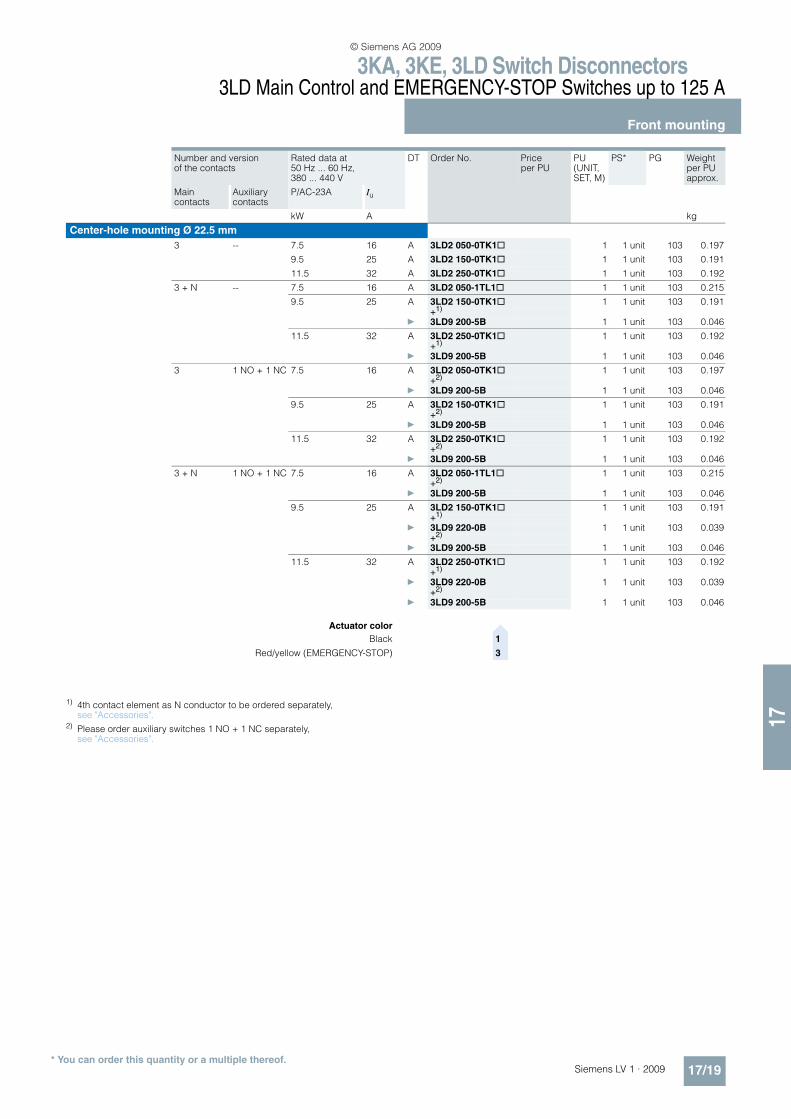
1) 4th contact element as N conductor to be ordered separately, see "Accessories".
2) Please order auxiliary switches 1 NO + 1 NC separately, see "Accessories".
Number and version of the contacts
Rated data at 50 Hz ... 60 Hz, 380 ... 440 V
DT Order No. Price per PU
PU (UNIT, SET, M)
PS* PG Weight per PU approx.
Main contacts
Auxiliary contacts
P/AC-23A Iu
kW A kg
Center-hole mounting Ø 22.5 mm
3 -- 7.5 16 A 3LD2 050-0TK1@ 1 1 unit 103 0.197
9.5 25 A 3LD2 150-0TK1@ 1 1 unit 103 0.191
11.5 32 A 3LD2 250-0TK1@ 1 1 unit 103 0.192
3 + N -- 7.5 16 A 3LD2 050-1TL1@ 1 1 unit 103 0.215
9.5 25 A 3LD2 150-0TK1@ 1 1 unit 103 0.191+1)
} 3LD9 200-5B 1 1 unit 103 0.046
11.5 32 A 3LD2 250-0TK1@ 1 1 unit 103 0.192+1)
} 3LD9 200-5B 1 1 unit 103 0.046
3 1 NO + 1 NC 7.5 16 A 3LD2 050-0TK1@ 1 1 unit 103 0.197+2)
} 3LD9 200-5B 1 1 unit 103 0.046
9.5 25 A 3LD2 150-0TK1@ 1 1 unit 103 0.191+2)
} 3LD9 200-5B 1 1 unit 103 0.046
11.5 32 A 3LD2 250-0TK1@ 1 1 unit 103 0.192+2)
} 3LD9 200-5B 1 1 unit 103 0.046
3 + N 1 NO + 1 NC 7.5 16 A 3LD2 050-1TL1@ 1 1 unit 103 0.215+2)
} 3LD9 200-5B 1 1 unit 103 0.046
9.5 25 A 3LD2 150-0TK1@ 1 1 unit 103 0.191+1)
} 3LD9 220-0B 1 1 unit 103 0.039+2)
} 3LD9 200-5B 1 1 unit 103 0.046
11.5 32 A 3LD2 250-0TK1@ 1 1 unit 103 0.192+1)
} 3LD9 220-0B 1 1 unit 103 0.039+2)
} 3LD9 200-5B 1 1 unit 103 0.046
Actuator color>
Black 1
Red/yellow (EMERGENCY-STOP) 3
© Siemens AG 2009

3KA, 3KE, 3LD Switch Disconnectors3LD Main Control and EMERGENCY-STOP Switches up to 125 A
Front mounting
17/20 Siemens LV 1 · 2009* You can order this quantity or a multiple thereof.
17
:
Number and version of the contacts
Rated data at 50 ... 60 Hz, 380 ... 440 V
DT Order No. Price per PU
PU (UNIT, SET, M)
PS* PG Weight per PU approx.
Main contacts
Auxiliary contacts
P/AC-3 P/AC-23A Iu
kW kW A kg
3LD2 103-3VK53
Main control and EMERGENCY-STOP switches with rotary operating mechanism/knob-operat-ed mechanism
• Lockable in 0 position with up to 3 padlocks
• Degree of protection at front side IP65
• All versions with rotary operating mechanism Exception: 3LD2 3 and 3LD2 4 with knob-operated mechanism
• Including terminal cover for the infeed side
• Front plate- 3LD2 0, 3LD2 1, 3LD2 2: 67 mm × 67 mm- 3LD2 5: 90 mm × 90 mm
6 -- 7.5 9.5 25 A 3LD2 103-3VK5@ 1 1 unit 103 0.380
9.5 11.5 32 A 3LD2 203-3VK5@ 1 1 unit 103 0.381
18.5 22.0 63 A 3LD2 504-3VK5@ 1 1 unit 103 0.854
6 1 NO + 1 NC
7.5 9.5 25 A 3LD2 103-4VP5@ 1 1 unit 103 0.432
Actuator color>
Black 1
Red/yellow (EMERGENCY-STOP) 3
Number and version of the contacts
Rated data at 50 ... 60 Hz, 380 ... 440 V
DT Order No. Price per PU
PU (UNIT, SET, M)
PS* PG Weight per PU approx.
Main contacts
Auxiliary contacts
P/AC-3 P/AC-23A Iu
kW kW A kg
3LD2 123-7UK01
Changeover switches with knob-operated mecha-nism
• Black actuator
• Knob-operated mechanism on 3LD2 3 and 3LD2 4 is lockableon all other versions it is non-lockable
• Degree of protection at front side IP65
3 -- 7.5 9.5 25 A 3LD2 123-7UK01 1 1 unit 103 0.374
9.5 11.5 32 A 3LD2 223-7UK01 1 1 unit 103 0.378
18.5 22.0 63 A 3LD2 524-7UK01 1 1 unit 103 0.841
30.0 37.0 100 A 3LD2 724-7UK01 1 1 unit 103 1.061
© Siemens AG 2009
3KA, 3KE, 3LD Switch Disconnectors3LD Main Control and EMERGENCY-STOP Switches up to 125 A
Floor mounting
17/21Siemens LV 1 · 2009* You can order this quantity or a multiple thereof.
17
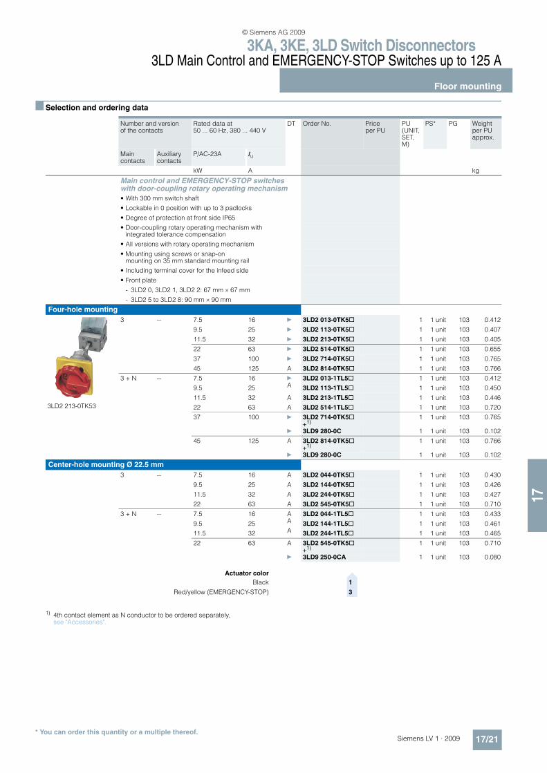
n Selection and ordering data
1) 4th contact element as N conductor to be ordered separately, see "Accessories".
Number and version of the contacts
Rated data at 50 ... 60 Hz, 380 ... 440 V
DT Order No. Price per PU
PU (UNIT, SET, M)
PS* PG Weight per PU approx.
Main contacts
Auxiliary contacts
P/AC-23A Iu
kW A kg
Main control and EMERGENCY-STOP switcheswith door-coupling rotary operating mechanism
• With 300 mm switch shaft
• Lockable in 0 position with up to 3 padlocks
• Degree of protection at front side IP65
• Door-coupling rotary operating mechanism withintegrated tolerance compensation
• All versions with rotary operating mechanism
• Mounting using screws or snap-on mounting on 35 mm standard mounting rail
• Including terminal cover for the infeed side
• Front plate
- 3LD2 0, 3LD2 1, 3LD2 2: 67 mm × 67 mm
- 3LD2 5 to 3LD2 8: 90 mm × 90 mm
Four-hole mounting
3LD2 213-0TK53
3 -- 7.5 16 } 3LD2 013-0TK5@ 1 1 unit 103 0.412
9.5 25 } 3LD2 113-0TK5@ 1 1 unit 103 0.407
11.5 32 } 3LD2 213-0TK5@ 1 1 unit 103 0.405
22 63 } 3LD2 514-0TK5@ 1 1 unit 103 0.655
37 100 } 3LD2 714-0TK5@ 1 1 unit 103 0.765
45 125 A 3LD2 814-0TK5@ 1 1 unit 103 0.766
3 + N -- 7.5 16 } 3LD2 013-1TL5@ 1 1 unit 103 0.412
9.5 25 A 3LD2 113-1TL5@ 1 1 unit 103 0.450
11.5 32 A 3LD2 213-1TL5@ 1 1 unit 103 0.446
22 63 A 3LD2 514-1TL5@ 1 1 unit 103 0.720
37 100 } 3LD2 714-0TK5@ 1 1 unit 103 0.765+1)
} 3LD9 280-0C 1 1 unit 103 0.102
45 125 A 3LD2 814-0TK5@ 1 1 unit 103 0.766+1)
} 3LD9 280-0C 1 1 unit 103 0.102
Center-hole mounting Ø 22.5 mm
3 -- 7.5 16 A 3LD2 044-0TK5@ 1 1 unit 103 0.430
9.5 25 A 3LD2 144-0TK5@ 1 1 unit 103 0.426
11.5 32 A 3LD2 244-0TK5@ 1 1 unit 103 0.427
22 63 A 3LD2 545-0TK5@ 1 1 unit 103 0.710
3 + N -- 7.5 16 A 3LD2 044-1TL5@ 1 1 unit 103 0.433
9.5 25 A 3LD2 144-1TL5@ 1 1 unit 103 0.461
11.5 32 A 3LD2 244-1TL5@ 1 1 unit 103 0.465
22 63 A 3LD2 545-0TK5@ 1 1 unit 103 0.710+1)
} 3LD9 250-0CA 1 1 unit 103 0.080
Actuator color>
Black 1
Red/yellow (EMERGENCY-STOP) 3
© Siemens AG 2009
3KA, 3KE, 3LD Switch Disconnectors3LD Main Control and EMERGENCY-STOP Switches up to 125 A
Floor mounting
17/22 Siemens LV 1 · 2009* You can order this quantity or a multiple thereof.
17
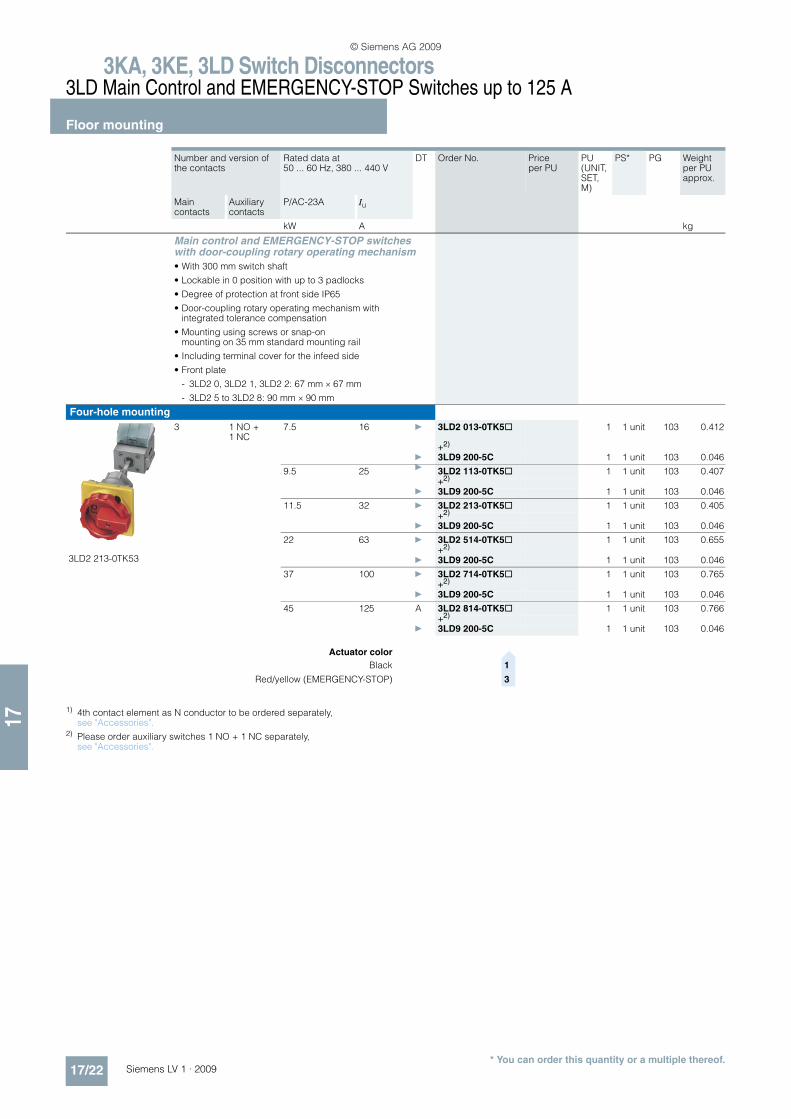
1) 4th contact element as N conductor to be ordered separately, see "Accessories".
2) Please order auxiliary switches 1 NO + 1 NC separately, see "Accessories".
Number and version of the contacts
Rated data at 50 ... 60 Hz, 380 ... 440 V
DT Order No. Price per PU
PU (UNIT, SET, M)
PS* PG Weight per PU approx.
Main contacts
Auxiliary contacts
P/AC-23A Iu
kW A kg
Main control and EMERGENCY-STOP switcheswith door-coupling rotary operating mechanism
• With 300 mm switch shaft
• Lockable in 0 position with up to 3 padlocks
• Degree of protection at front side IP65
• Door-coupling rotary operating mechanism with integrated tolerance compensation
• Mounting using screws or snap-on mounting on 35 mm standard mounting rail
• Including terminal cover for the infeed side
• Front plate
- 3LD2 0, 3LD2 1, 3LD2 2: 67 mm × 67 mm
- 3LD2 5 to 3LD2 8: 90 mm × 90 mm
Four-hole mounting
3LD2 213-0TK53
3 1 NO + 1 NC
7.5 16 } 3LD2 013-0TK5@ 1 1 unit 103 0.412
+2)
} 3LD9 200-5C 1 1 unit 103 0.046
9.5 25 } 3LD2 113-0TK5@ 1 1 unit 103 0.407+2)
} 3LD9 200-5C 1 1 unit 103 0.046
11.5 32 } 3LD2 213-0TK5@ 1 1 unit 103 0.405+2)
} 3LD9 200-5C 1 1 unit 103 0.046
22 63 } 3LD2 514-0TK5@ 1 1 unit 103 0.655+2)
} 3LD9 200-5C 1 1 unit 103 0.046
37 100 } 3LD2 714-0TK5@ 1 1 unit 103 0.765+2)
} 3LD9 200-5C 1 1 unit 103 0.046
45 125 A 3LD2 814-0TK5@ 1 1 unit 103 0.766+2)
} 3LD9 200-5C 1 1 unit 103 0.046
Actuator color>
Black 1
Red/yellow (EMERGENCY-STOP) 3
© Siemens AG 2009
3KA, 3KE, 3LD Switch Disconnectors3LD Main Control and EMERGENCY-STOP Switches up to 125 A
Floor mounting
17/23Siemens LV 1 · 2009* You can order this quantity or a multiple thereof.
17
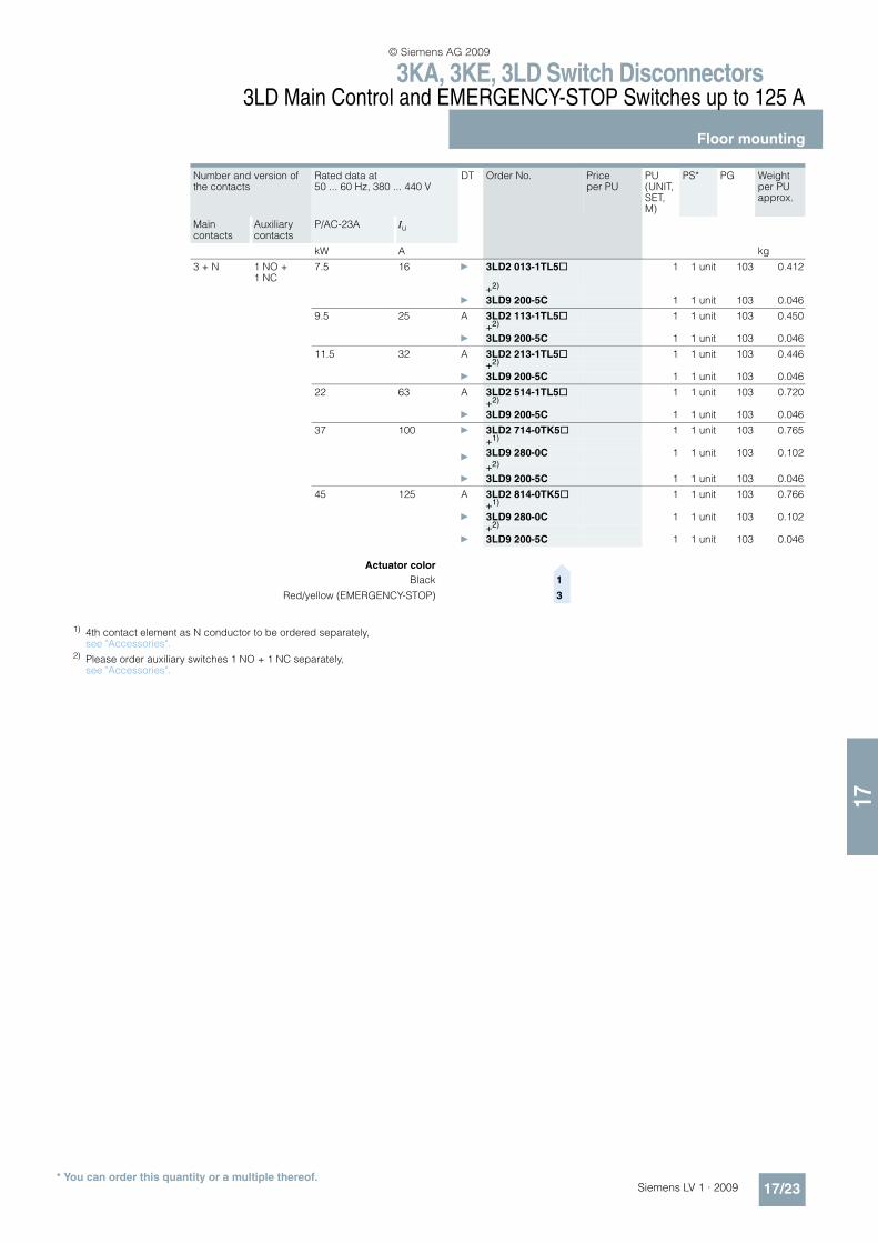
1) 4th contact element as N conductor to be ordered separately, see "Accessories".
2) Please order auxiliary switches 1 NO + 1 NC separately, see "Accessories".
Number and version of the contacts
Rated data at 50 ... 60 Hz, 380 ... 440 V
DT Order No. Price per PU
PU (UNIT, SET, M)
PS* PG Weight per PU approx.
Main contacts
Auxiliary contacts
P/AC-23A Iu
kW A kg
3 + N 1 NO + 1 NC
7.5 16 } 3LD2 013-1TL5@ 1 1 unit 103 0.412
+2)
} 3LD9 200-5C 1 1 unit 103 0.046
9.5 25 A 3LD2 113-1TL5@ 1 1 unit 103 0.450+2)
} 3LD9 200-5C 1 1 unit 103 0.046
11.5 32 A 3LD2 213-1TL5@ 1 1 unit 103 0.446+2)
} 3LD9 200-5C 1 1 unit 103 0.046
22 63 A 3LD2 514-1TL5@ 1 1 unit 103 0.720+2)
} 3LD9 200-5C 1 1 unit 103 0.046
37 100 } 3LD2 714-0TK5@ 1 1 unit 103 0.765+1)
}3LD9 280-0C 1 1 unit 103 0.102
+2)
} 3LD9 200-5C 1 1 unit 103 0.046
45 125 A 3LD2 814-0TK5@ 1 1 unit 103 0.766+1)
} 3LD9 280-0C 1 1 unit 103 0.102+2)
} 3LD9 200-5C 1 1 unit 103 0.046
Actuator color>
Black 1
Red/yellow (EMERGENCY-STOP) 3
© Siemens AG 2009
3KA, 3KE, 3LD Switch Disconnectors3LD Main Control and EMERGENCY-STOP Switches up to 125 A
Floor mounting
17/24 Siemens LV 1 · 2009* You can order this quantity or a multiple thereof.
17
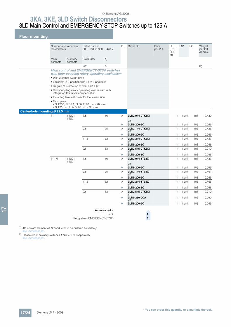
1) 4th contact element as N conductor to be ordered separately, see "Accessories".
2) Please order auxiliary switches 1 NO + 1 NC separately, see "Accessories".
Number and version of the contacts
Rated data at 50 ... 60 Hz, 380 ... 440 V
DT Order No. Price per PU
PU (UNIT, SET, M)
PS* PG Weight per PU approx.
Main contacts
Auxiliary contacts
P/AC-23A Iu
kW A kg
Main control and EMERGENCY-STOP switcheswith door-coupling rotary operating mechanism
• With 300 mm switch shaft
• Lockable in 0 position with up to 3 padlocks
• Degree of protection at front side IP65
• Door-coupling rotary operating mechanism with integrated tolerance compensation
• Including terminal cover for the infeed side
• Front plate- 3LD2 0, 3LD2 1, 3LD2 2: 67 mm × 67 mm- 3LD2 5 to 3LD2 8: 90 mm × 90 mm
Center-hole mounting Ø 22.5 mm
3 1 NO + 1 NC
7.5 16 A 3LD2 044-0TK5@ 1 1 unit 103 0.430
+2)
} 3LD9 200-5C 1 1 unit 103 0.046
9.5 25 A 3LD2 144-0TK5@ 1 1 unit 103 0.426+2)
} 3LD9 200-5C 1 1 unit 103 0.046
11.5 32 A 3LD2 244-0TK5@ 1 1 unit 103 0.427+2)
} 3LD9 200-5C 1 1 unit 103 0.046
22 63 A 3LD2 545-0TK5@ 1 1 unit 103 0.710+2)
} 3LD9 200-5C 1 1 unit 103 0.046
3 + N 1 NO + 1 NC
7.5 16 A 3LD2 044-1TL5@ 1 1 unit 103 0.433
+2)
} 3LD9 200-5C 1 1 unit 103 0.046
9.5 25 A 3LD2 144-1TL5@ 1 1 unit 103 0.461+2)
} 3LD9 200-5C 1 1 unit 103 0.046
11.5 32 A 3LD2 244-1TL5@ 1 1 unit 103 0.465+2)
} 3LD9 200-5C 1 1 unit 103 0.046
22 63 A 3LD2 545-0TK5@ 1 1 unit 103 0.710+1)
} 3LD9 250-0CA 1 1 unit 103 0.080+2)
} 3LD9 200-5C 1 1 unit 103 0.046
Actuator color>
Black 1
Red/yellow (EMERGENCY-STOP) 3
© Siemens AG 2009
3KA, 3KE, 3LD Switch Disconnectors3LD Main Control and EMERGENCY-STOP Switches up to 125 A
Floor mounting
17/25Siemens LV 1 · 2009* You can order this quantity or a multiple thereof.
17
Number and version of the contacts
Rated data at 50 ... 60 Hz, 380 ... 440 V
DT Order No. Price per PU
PU (UNIT, SET, M)
PS* PG Weight per PU approx.
Main contacts
Auxiliary contacts
P/AC-3 P/AC-23A Iu
kW kW A kg
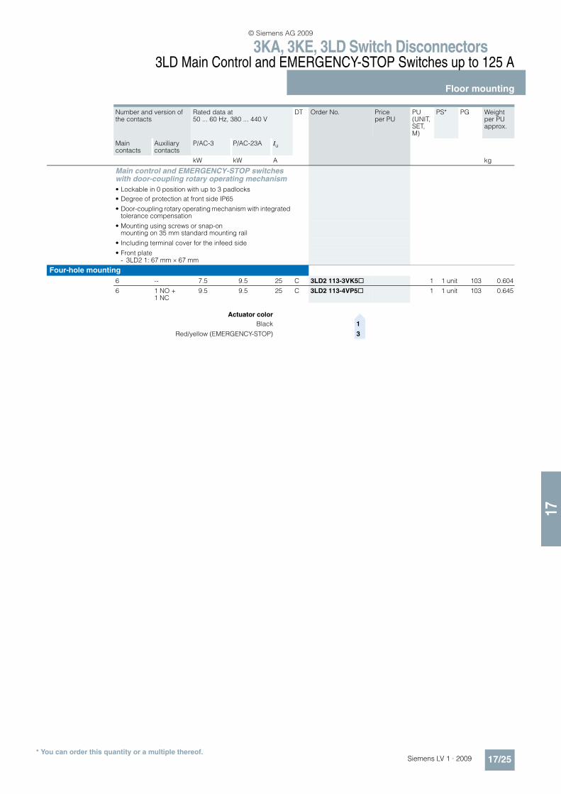
Main control and EMERGENCY-STOP switcheswith door-coupling rotary operating mechanism
• Lockable in 0 position with up to 3 padlocks
• Degree of protection at front side IP65
• Door-coupling rotary operating mechanism with integrated tolerance compensation
• Mounting using screws or snap-on mounting on 35 mm standard mounting rail
• Including terminal cover for the infeed side
• Front plate- 3LD2 1: 67 mm × 67 mm
Four-hole mounting
6 -- 7.5 9.5 25 C 3LD2 113-3VK5@ 1 1 unit 103 0.604
6 1 NO + 1 NC
9.5 9.5 25 C 3LD2 113-4VP5@ 1 1 unit 103 0.645
Actuator color>
Black 1
Red/yellow (EMERGENCY-STOP) 3
© Siemens AG 2009
3KA, 3KE, 3LD Switch Disconnectors3LD Main Control and EMERGENCY-STOP Switches up to 125 A
Floor mounting
17/26 Siemens LV 1 · 2009* You can order this quantity or a multiple thereof.
17
1) Auxiliary contact elements and miscellaneous accessories to be ordered separately, see "Accessories".
Number and version of the contacts
Rated data at 50 ... 60 Hz, 380 ... 440 V
DT Order No. Price per PU
PU (UNIT, SET, M)
PS* PG Weight per PU approx.
Main contacts
Auxiliary contacts
P/AC-23A Iu
kW A kg
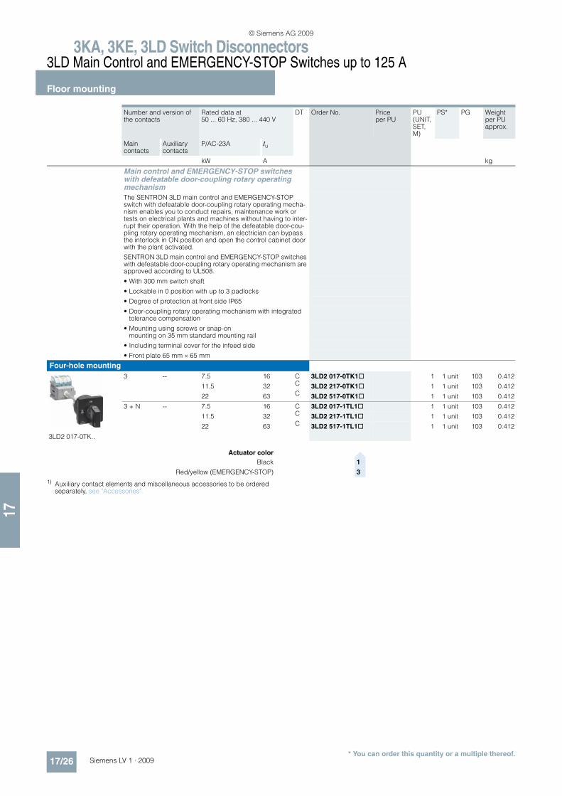
Main control and EMERGENCY-STOP switches with defeatable door-coupling rotary operating mechanism
The SENTRON 3LD main control and EMERGENCY-STOP switch with defeatable door-coupling rotary operating mecha-nism enables you to conduct repairs, maintenance work or tests on electrical plants and machines without having to inter-rupt their operation. With the help of the defeatable door-cou-pling rotary operating mechanism, an electrician can bypass the interlock in ON position and open the control cabinet door with the plant activated.
SENTRON 3LD main control and EMERGENCY-STOP switches with defeatable door-coupling rotary operating mechanism are approved according to UL508.
• With 300 mm switch shaft
• Lockable in 0 position with up to 3 padlocks
• Degree of protection at front side IP65
• Door-coupling rotary operating mechanism with integrated tolerance compensation
• Mounting using screws or snap-on mounting on 35 mm standard mounting rail
• Including terminal cover for the infeed side
• Front plate 65 mm × 65 mm
Four-hole mounting
3LD2 017-0TK..
3 -- 7.5 16 C 3LD2 017-0TK1@ 1 1 unit 103 0.412
11.5 32 C 3LD2 217-0TK1@ 1 1 unit 103 0.412
22 63 C 3LD2 517-0TK1@ 1 1 unit 103 0.412
3 + N -- 7.5 16 C 3LD2 017-1TL1@ 1 1 unit 103 0.412
11.5 32 C 3LD2 217-1TL1@ 1 1 unit 103 0.412
22 63 C 3LD2 517-1TL1@ 1 1 unit 103 0.412
Actuator color>
Black 1
Red/yellow (EMERGENCY-STOP) 3
© Siemens AG 2009
3KA, 3KE, 3LD Switch Disconnectors3LD Main Control and EMERGENCY-STOP Switches up to 125 A
Distribution board mounting
17/27Siemens LV 1 · 2009* You can order this quantity or a multiple thereof.
17
n Selection and ordering data
Number and version of the contacts
Rated data at 50 ... 60 Hz, 380 ... 440 V
DT Order No. Price per PU
PU (UNIT, SET, M)
PS* PG Weight per PU approx.
Main contacts
Auxiliary contacts
P/AC-23A Iu
kW A kg
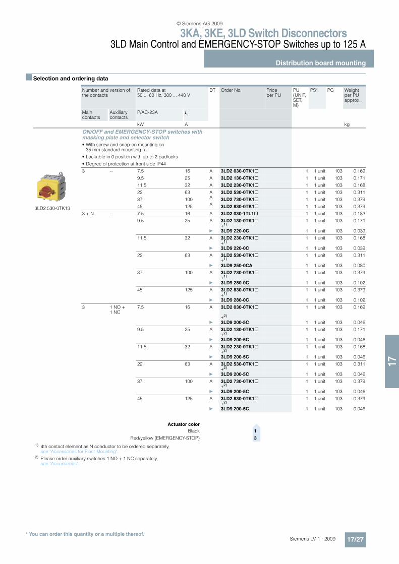
ON/OFF and EMERGENCY-STOP switches with masking plate and selector switch
• With screw and snap-on mounting on 35 mm standard mounting rail
• Lockable in 0 position with up to 2 padlocks
• Degree of protection at front side IP44
3LD2 530-0TK13
3 -- 7.5 16 A 3LD2 030-0TK1@ 1 1 unit 103 0.169
9.5 25 A 3LD2 130-0TK1@ 1 1 unit 103 0.171
11.5 32 A 3LD2 230-0TK1@ 1 1 unit 103 0.168
22 63 A 3LD2 530-0TK1@ 1 1 unit 103 0.311
37 100 A 3LD2 730-0TK1@ 1 1 unit 103 0.379
45 125 A 3LD2 830-0TK1@ 1 1 unit 103 0.379
3 + N -- 7.5 16 A 3LD2 030-1TL1@ 1 1 unit 103 0.183
9.5 25 A 3LD2 130-0TK1@ 1 1 unit 103 0.171+1)
} 3LD9 220-0C 1 1 unit 103 0.039
11.5 32 A 3LD2 230-0TK1@ 1 1 unit 103 0.168+1)
} 3LD9 220-0C 1 1 unit 103 0.039
22 63 A 3LD2 530-0TK1@ 1 1 unit 103 0.311+1)
} 3LD9 250-0CA 1 1 unit 103 0.080
37 100 A 3LD2 730-0TK1@ 1 1 unit 103 0.379+1)
} 3LD9 280-0C 1 1 unit 103 0.102
45 125 A 3LD2 830-0TK1@ 1 1 unit 103 0.379+1)
} 3LD9 280-0C 1 1 unit 103 0.102
3 1 NO + 1 NC
7.5 16 A 3LD2 030-0TK1@ 1 1 unit 103 0.169
+2)
} 3LD9 200-5C 1 1 unit 103 0.046
9.5 25 A 3LD2 130-0TK1@ 1 1 unit 103 0.171+2)
} 3LD9 200-5C 1 1 unit 103 0.046
11.5 32 A 3LD2 230-0TK1@ 1 1 unit 103 0.168+2)
} 3LD9 200-5C 1 1 unit 103 0.046
22 63 A 3LD2 530-0TK1@ 1 1 unit 103 0.311+2)
} 3LD9 200-5C 1 1 unit 103 0.046
37 100 A 3LD2 730-0TK1@ 1 1 unit 103 0.379+2)
} 3LD9 200-5C 1 1 unit 103 0.046
45 125 A 3LD2 830-0TK1@ 1 1 unit 103 0.379+2)
} 3LD9 200-5C 1 1 unit 103 0.046
1) 4th contact element as N conductor to be ordered separately, see "Accessories for Floor Mounting".
2) Please order auxiliary switches 1 NO + 1 NC separately, see "Accessories".
Actuator color>
Black 1
Red/yellow (EMERGENCY-STOP) 3
© Siemens AG 2009

3KA, 3KE, 3LD Switch Disconnectors3LD Main Control and EMERGENCY-STOP Switches up to 125 A
Distribution board mounting
17/28 Siemens LV 1 · 2009* You can order this quantity or a multiple thereof.
17
1) 4th contact element as N conductor to be ordered separately, see "Accessories for Floor Mounting".
2) Please order auxiliary switches 1 NO + 1 NC separately, see "Accessories".
3 + N 1 NO + 1 NC
7.5 16 A 3LD2 030-1TL1@ 1 1 unit 103 0.183
+2)
} 3LD9 200-5C 1 1 unit 103 0.046
9.5 25 A 3LD2 130-0TK1@ 1 1 unit 103 0.171+2)
} 3LD9 200-5C 1 1 unit 103 0.046+1)
} 3LD9 220-0C 1 1 unit 103 0.039
11.5 32 A 3LD2 230-0TK1@ 1 1 unit 103 0.168+2)
} 3LD9 200-5C 1 1 unit 103 0.046+1)
} 3LD9 220-0C 1 1 unit 103 0.039
22 63 A 3LD2 530-0TK1@ 1 1 unit 103 0.311+2)
} 3LD9 200-5C 1 1 unit 103 0.046+1)
} 3LD9 250-0CA 1 1 unit 103 0.080
37 100 A 3LD2 730-0TK1@ 1 1 unit 103 0.379+2)
} 3LD9 200-5C 1 1 unit 103 0.046+1)
} 3LD9 280-0C 1 1 unit 103 0.102
45 125 A 3LD2 830-0TK1@ 1 1 unit 103 0.379+2)
} 3LD9 200-5C 1 1 unit 103 0.046+1)
} 3LD9 280-0C 1 1 unit 103 0.102
Actuator color>
Black 1
Red/yellow (EMERGENCY-STOP) 3
Number and version of the contacts
Rated data at 50 ... 60 Hz, 380 ... 440 V
DT Order No. Price per PU
PU (UNIT, SET, M)
PS* PG Weight per PU approx.
Main contacts
Auxiliary contacts
P/AC-23A Iu
kW A kg
© Siemens AG 2009
3KA, 3KE, 3LD Switch Disconnectors3LD Main Control and EMERGENCY-STOP Switches up to 125 A
Molded-plastic enclosures
17/29Siemens LV 1 · 2009* You can order this quantity or a multiple thereof.
17
n Selection and ordering data
1) 4th contact element as N conductor to be ordered separately, see "Accessories for Floor Mounting".
2) Please order auxiliary switches 1 NO + 1 NC separately, see "Accessories".
Number and version of the contacts
Base terminal
Rated data at 50 ... 60 Hz, 380 ... 440 V
DT Order No. Price per PU
PU (UNIT, SET, M)
PS* PG Weight per PU approx.
Main contacts
Auxiliary contacts
P/AC-23A Iu
kW A kg
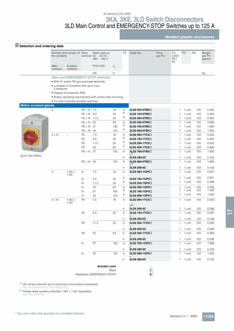
Main and EMERGENCY-STOP switches
• With N- and/or PE-/ground base terminals
• Lockable in 0 position with up to max. 3 padlocks
• Degree of protection IP65
• Rotary operating mechanisms with center-hole mounting
• For floor-mounted auxiliary switches
Metric screwed glands
3LD2 164-0TB53
3 -- PE + N 7.5 16 A 3LD2 064-0TB5@ 1 1 unit 103 0.463
PE + N 9.5 25 A 3LD2 164-0TB5@ 1 1 unit 103 0.463
PE + N 11.5 32 A 3LD2 264-0TB5@ 1 1 unit 103 0.465
PE + N 22 63 A 3LD2 565-0TB5@ 1 1 unit 103 0.906
PE + N 37 100 A 3LD2 766-0TB5@ 1 1 unit 103 1.890
PE + N 45 125 A 3LD2 866-0TB5@ 1 1 unit 103 1.890
3 + N -- PE 7.5 16 A 3LD2 064-1TC5@ 1 1 unit 103 0.453
PE 9.5 25 A 3LD2 164-1TC5@ 1 1 unit 103 0.487
PE 11.5 32 C 3LD2 264-1TC5@ 1 1 unit 103 0.500
PE 22 63 C 3LD2 565-1TC5@ 1 1 unit 103 0.960
PE + N 37 100 A 3LD2 766-0TB5@ 1 1 unit 103 1.890+1)
} 3LD9 280-0C 1 1 unit 103 0.102
PE + N 45 125 A 3LD2 866-0TB5@ 1 1 unit 103 1.890+1)
} 3LD9 280-0C 1 1 unit 103 0.102
3 1 NO + 1 NC
N 7.5 16 A 3LD2 064-1GP5@ 1 1 unit 103 0.507
N 9.5 25 A 3LD2 164-1GP5@ 1 1 unit 103 0.501
N 11.5 32 A 3LD2 264-1GP5@ 1 1 unit 103 0.488
N 22 63 A 3LD2 565-1GP5@ 1 1 unit 103 0.935
N 37 100 A 3LD2 766-1GP5@ 1 1 unit 103 1.838
N 45 125 A 3LD2 866-1GP5@ 1 1 unit 103 1.843
3 + N 1 NO + 1 NC
PE 7.5 16 A 3LD2 064-1TC5@ 1 1 unit 103 0.453
+2)
} 3LD9 200-5C 1 1 unit 103 0.046
PE 9.5 25 A 3LD2 164-1TC5@ 1 1 unit 103 0.487+
} 3LD9 200-5C 1 1 unit 103 0.046
PE 11.5 32 C 3LD2 264-1TC5@ 1 1 unit 103 0.500+
} 3LD9 200-5C 1 1 unit 103 0.046
PE 22 63 C 3LD2 565-1TC5@ 1 1 unit 103 0.960+
} 3LD9 200-5C 1 1 unit 103 0.046
N 37 100 A 3LD2 766-1GP5@ 1 1 unit 103 1.838+
} 3LD9 280-0C 1 1 unit 103 0.102
N 45 125 A 3LD2 866-1GP5@ 1 1 unit 103 1.843+
} 3LD9 280-0C 1 1 unit 103 0.102
Actuator color>
Black 1
Red/yellow (EMERGENCY-STOP) 3
© Siemens AG 2009

3KA, 3KE, 3LD Switch Disconnectors3LD Main Control and EMERGENCY-STOP Switches up to 125 A
Molded-plastic enclosures
17/30 Siemens LV 1 · 2009* You can order this quantity or a multiple thereof.
17
Number and version of the contacts
Base terminal
Rated data at 50 ... 60 Hz, 380 ... 440 V
DT Order No. Price per PU
PU (UNIT, SET, M)
PS* PG Weight per PU approx.
Main contacts
Auxiliary contacts
P/AC-3 P/AC-23A Iu
kW kW A kg
Main and EMERGENCY-STOP switcheswith rotary operating mechanism
• With N- and/or PE-/ground base terminals
• Degree of protection IP65
Metric screwed glands
3LD2 165-3VB53
6 -- PE + N 7.5 9.5 25 A 3LD2 165-3VB5@ 1 1 unit 103 0.880
PE + N 9.5 11.5 32 A 3LD2 265-3VB5@ 1 1 unit 103 0.878
PE + N 18.5 22.0 63 A 3LD2 566-3VB5@ 1 1 unit 103 2.105
6 1 NO + 1 NC
N 7.5 9.5 25 A 3LD2 165-4VD5@ 1 1 unit 103 0.914
N 9.5 11.5 32 A 3LD2 265-4VD5@ 1 1 unit 103 0.910
PE + N 18.5 22.0 63 A 3LD2 566-4VD5@ 1 1 unit 103 2.084
Actuator color>
Black 1
Red/yellow (EMERGENCY-STOP) 3
Number and version of the contacts
Base terminal
Rated data at 50 ... 60 Hz, 380 ... 440 V
DT Order No. Price per PU
PU (UNIT, SET, M)
PS* PG Weight per PU approx.
Main contacts
Auxiliary contacts
P/AC-3 P/AC-23A Iu
kW kW A kg
Changeover switches with knob-operated mecha-nism, knob cannot be locked
• With N- and/or PE-/ground base terminals
• Black actuator
• Degree of protection IP65
Metric screwed glands
3LD2 165-7UB01
6 -- PE + N 7.5 9.5 25 A 3LD2 165-7UB01 1 1 unit 103 0.888
PE + N 9.5 11.5 32 A 3LD2 265-7UB01 1 1 unit 103 0.888
PE + N 18.5 22.0 63 A 3LD2 566-7UB01 1 1 unit 103 2.105
PE + N 30.0 37.0 100 A 3LD2 766-7UB01 1 1 unit 103 2.335
© Siemens AG 2009
3KA, 3KE, 3LD Switch Disconnectors3LD Main Control and EMERGENCY-STOP Switches up to 125 A
Accessories
17/31Siemens LV 1 · 2009* You can order this quantity or a multiple thereof.
17
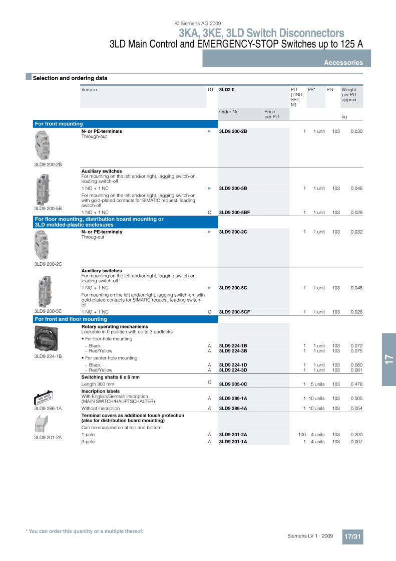
n Selection and ordering data
Version DT 3LD2 0 PU (UNIT, SET, M)
PS* PG Weight per PU approx.
Order No. Price per PU kg
For front mounting
3LD9 200-2B
N- or PE-terminals } 3LD9 200-2B 1 1 unit 103 0.030Through-out
3LD9 200-5B
Auxiliary switchesFor mounting on the left and/or right, lagging switch-on, leading switch-off
1 NO + 1 NC } 3LD9 200-5B 1 1 unit 103 0.046
For mounting on the left and/or right, lagging switch-on, with gold-plated contacts for SIMATIC request, leading switch-off
1 NO + 1 NC C 3LD9 200-5BF 1 1 unit 103 0.028
For floor mounting, distribution board mounting or 3LD molded-plastic enclosures
3LD9 200-2C
N- or PE-terminals } 3LD9 200-2C 1 1 unit 103 0.032Throug-out
3LD9 200-5C
Auxiliary switchesFor mounting on the left and/or right, lagging switch-on, leading switch-off
1 NO + 1 NC } 3LD9 200-5C 1 1 unit 103 0.046
For mounting on the left and/or right, lagging switch-on, with gold-plated contacts for SIMATIC request, leading switch-off
1 NO + 1 NC C 3LD9 200-5CF 1 1 unit 103 0.028
For front and floor mounting
3LD9 224-1B
Rotary operating mechanismsLockable in 0 position with up to 3 padlocks
• For four-hole mounting
- Black A 3LD9 224-1B 1 1 unit 103 0.072- Red/Yellow A 3LD9 224-3B 1 1 unit 103 0.075
• For center-hole mounting
- Black A 3LD9 224-1D 1 1 unit 103 0.080- Red/Yellow A 3LD9 224-3D 1 1 unit 103 0.081
Switching shafts 6 x 6 mm
Length 300 mm C 3LD9 205-0C 1 5 units 103 0.476
3LD9 286-1A
Inscription labelsWith English/German inscription (MAIN SWITCH/HAUPTSCHALTER)
A 3LD9 286-1A 1 10 units 103 0.005
Without inscription A 3LD9 286-4A 1 10 units 103 0.054
3LD9 201-2A
Terminal covers as additional touch protection (also for distribution board mounting)
Can be snapped on at top and bottom
1-pole A 3LD9 201-2A 100 4 units 103 0.200
3-pole A 3LD9 201-1A 1 4 units 103 0.007
© Siemens AG 2009

3KA, 3KE, 3LD Switch Disconnectors3LD Main Control and EMERGENCY-STOP Switches up to 125 A
Accessories
17/32 Siemens LV 1 · 2009* You can order this quantity or a multiple thereof.
17
Version DT 3LD2 1 and 3LD2 2 PU (UNIT, SET, M)
PS* PG Weight per PU approx.
Order No. Price per PU kg
For front mounting
3LD9 220-0B
4th contact (N conductor) } 3LD9 220-0B 1 1 unit 103 0.039Leading switch-on, lagging switch-off
3LD9 220-2B
N- or PE-terminals } 3LD9 220-2B 1 1 unit 103 0.036Through-out
3LD9 200-5B
Auxiliary switchesFor mounting on the left and/or right, lagging switch-on, leading switch-off
1 NO + 1 NC } 3LD9 200-5B 1 1 unit 103 0.046
For mounting on the left and/or right, lagging switch-on, leading switch-off, with gold-plated contacts for SIMATIC request
1 NO + 1 NC C 3LD9 200-5BF 1 1 unit 103 0.028
For floor mounting, distribution board mounting or 3LD molded-plastic enclosures
3LD9 220-0C
4th contact (N conductor) } 3LD9 220-0C 1 1 unit 103 0.039Leading switch-on, lagging switch-off
N- or PE-terminals } 3LD9 220-2C 1 1 unit 103 0.037Through-out
3LD9 200-5C
Auxiliary switchesFor mounting on the left and/or right, lagging switch-on, leading switch-off
1 NO + 1 NC } 3LD9 200-5C 1 1 unit 103 0.046
For mounting on the left and/or right, lagging switch-on, leading switch-off, with gold-plated contacts for SIMATIC request
1 NO + 1 NC C 3LD9 200-5CF 1 1 unit 103 0.028
For front and floor mounting
3LD9 224-1B
Rotary operating mechanismsLockable in 0 position with up to 3 padlocks
• For four-hole mounting
- Black A 3LD9 224-1B 1 1 unit 103 0.072- Red/Yellow A 3LD9 224-3B 1 1 unit 103 0.075
• For center-hole mounting
- Black A 3LD9 224-1D 1 1 unit 103 0.080- Red/Yellow A 3LD9 224-3D 1 1 unit 103 0.081
Switching shafts 6 x 6 mm
Length 300 mm C 3LD9 205-0C 1 5 units 103 0.476
3LD9 286-1A
Inscription labelsWith English/German inscription (MAIN SWITCH/HAUPTSCHALTER)
A 3LD9 286-1A 1 10 units 103 0.005
Without inscription A 3LD9 286-4A 1 10 units 103 0.054
3LD9 221-2A
Terminal covers as additional touch protection (also for distribution board mounting)Can be snapped on at top and bottom
1-pole A 3LD9 221-2A 100 4 units 103 0.100
3LD9 221-0A
3-pole A 3LD9 221-0A 1 4 units 103 0.007
© Siemens AG 2009
3KA, 3KE, 3LD Switch Disconnectors3LD Main Control and EMERGENCY-STOP Switches up to 125 A
Accessories
17/33Siemens LV 1 · 2009* You can order this quantity or a multiple thereof.
17
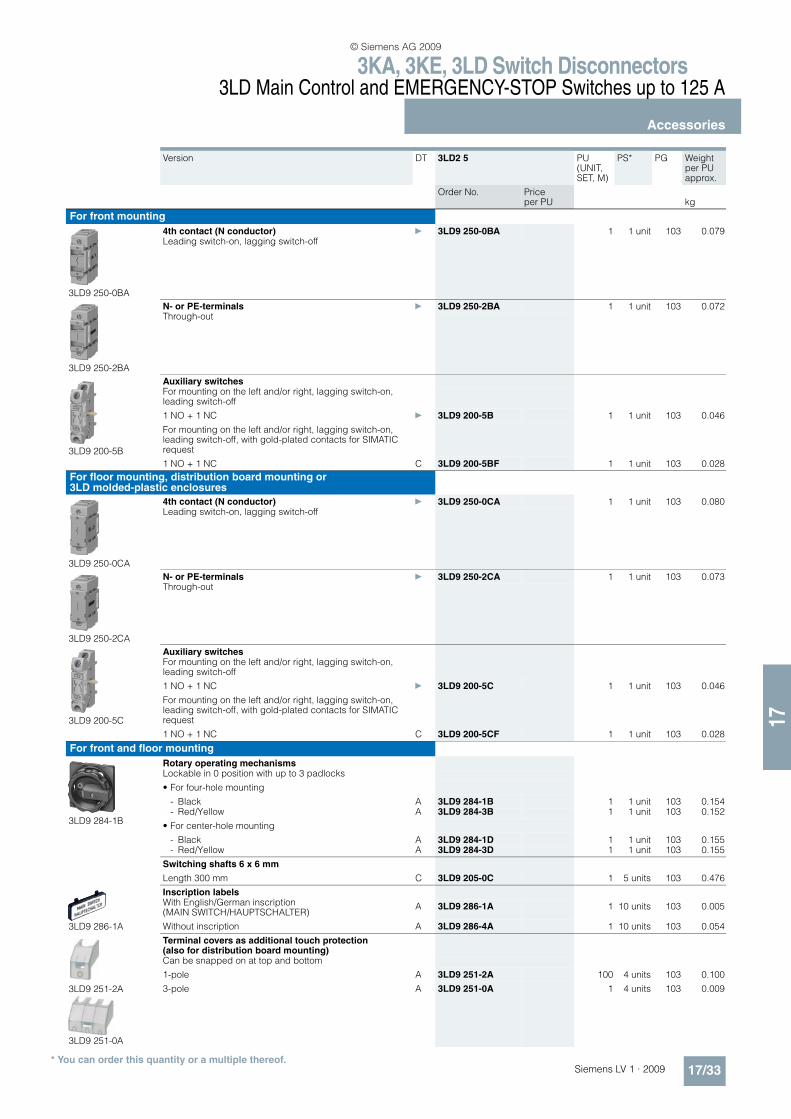
Version DT 3LD2 5 PU (UNIT, SET, M)
PS* PG Weight per PU approx.
Order No. Price per PU kg
For front mounting
3LD9 250-0BA
4th contact (N conductor) } 3LD9 250-0BA 1 1 unit 103 0.079Leading switch-on, lagging switch-off
3LD9 250-2BA
N- or PE-terminals } 3LD9 250-2BA 1 1 unit 103 0.072Through-out
3LD9 200-5B
Auxiliary switchesFor mounting on the left and/or right, lagging switch-on, leading switch-off
1 NO + 1 NC } 3LD9 200-5B 1 1 unit 103 0.046
For mounting on the left and/or right, lagging switch-on, leading switch-off, with gold-plated contacts for SIMATIC request
1 NO + 1 NC C 3LD9 200-5BF 1 1 unit 103 0.028
For floor mounting, distribution board mounting or 3LD molded-plastic enclosures
3LD9 250-0CA
4th contact (N conductor) } 3LD9 250-0CA 1 1 unit 103 0.080Leading switch-on, lagging switch-off
3LD9 250-2CA
N- or PE-terminals } 3LD9 250-2CA 1 1 unit 103 0.073Through-out
3LD9 200-5C
Auxiliary switchesFor mounting on the left and/or right, lagging switch-on, leading switch-off
1 NO + 1 NC } 3LD9 200-5C 1 1 unit 103 0.046
For mounting on the left and/or right, lagging switch-on, leading switch-off, with gold-plated contacts for SIMATIC request
1 NO + 1 NC C 3LD9 200-5CF 1 1 unit 103 0.028
For front and floor mounting
3LD9 284-1B
Rotary operating mechanismsLockable in 0 position with up to 3 padlocks
• For four-hole mounting
- Black A 3LD9 284-1B 1 1 unit 103 0.154- Red/Yellow A 3LD9 284-3B 1 1 unit 103 0.152
• For center-hole mounting
- Black A 3LD9 284-1D 1 1 unit 103 0.155- Red/Yellow A 3LD9 284-3D 1 1 unit 103 0.155
Switching shafts 6 x 6 mm
Length 300 mm C 3LD9 205-0C 1 5 units 103 0.476
3LD9 286-1A
Inscription labelsWith English/German inscription (MAIN SWITCH/HAUPTSCHALTER)
A 3LD9 286-1A 1 10 units 103 0.005
Without inscription A 3LD9 286-4A 1 10 units 103 0.054
3LD9 251-2A
3LD9 251-0A
Terminal covers as additional touch protection (also for distribution board mounting)Can be snapped on at top and bottom
1-pole A 3LD9 251-2A 100 4 units 103 0.100
3-pole A 3LD9 251-0A 1 4 units 103 0.009
© Siemens AG 2009
3KA, 3KE, 3LD Switch Disconnectors3LD Main control and EMERGENCY-STOP Switches up to 125 A
Accessories
17/34 Siemens LV 1 · 2009* You can order this quantity or a multiple thereof.
17
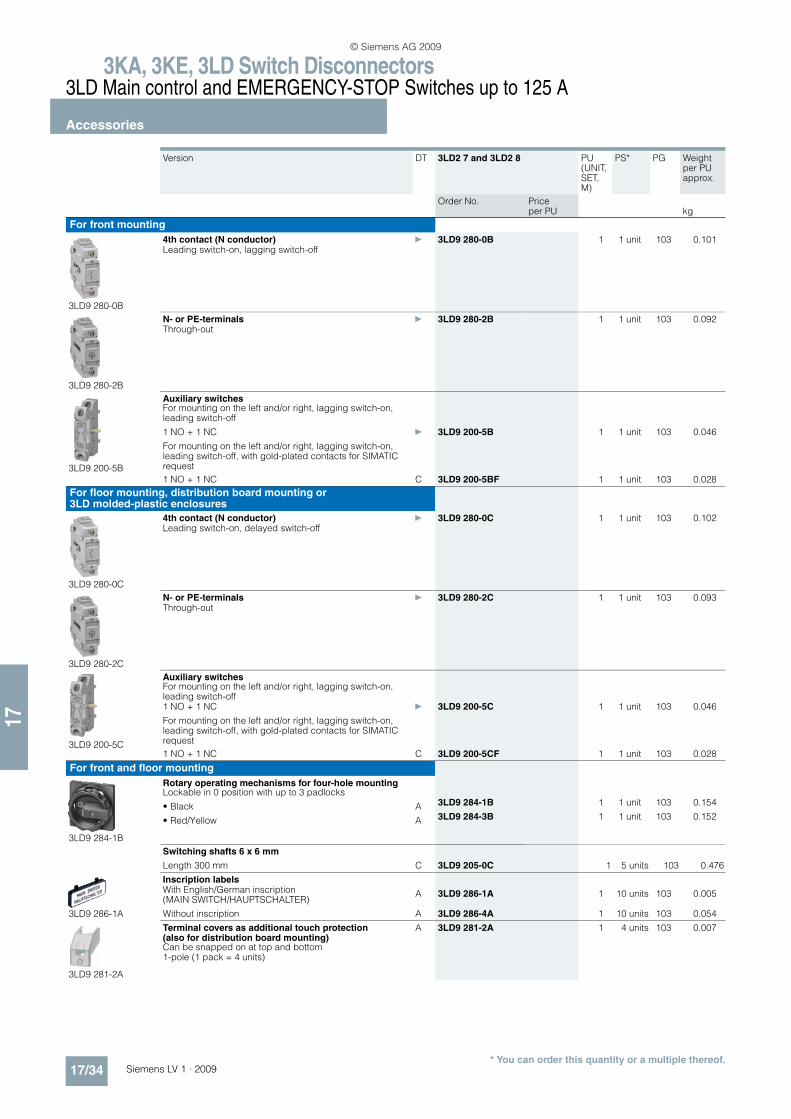
Version DT 3LD2 7 and 3LD2 8 PU (UNIT, SET, M)
PS* PG Weight per PU approx.
Order No. Price per PU kg
For front mounting
3LD9 280-0B
4th contact (N conductor) } 3LD9 280-0B 1 1 unit 103 0.101Leading switch-on, lagging switch-off
3LD9 280-2B
N- or PE-terminals } 3LD9 280-2B 1 1 unit 103 0.092Through-out
3LD9 200-5B
Auxiliary switchesFor mounting on the left and/or right, lagging switch-on, leading switch-off
1 NO + 1 NC } 3LD9 200-5B 1 1 unit 103 0.046
For mounting on the left and/or right, lagging switch-on, leading switch-off, with gold-plated contacts for SIMATIC request
1 NO + 1 NC C 3LD9 200-5BF 1 1 unit 103 0.028
For floor mounting, distribution board mounting or 3LD molded-plastic enclosures
3LD9 280-0C
4th contact (N conductor) } 3LD9 280-0C 1 1 unit 103 0.102Leading switch-on, delayed switch-off
3LD9 280-2C
N- or PE-terminals } 3LD9 280-2C 1 1 unit 103 0.093Through-out
3LD9 200-5C
Auxiliary switchesFor mounting on the left and/or right, lagging switch-on, leading switch-off1 NO + 1 NC } 3LD9 200-5C 1 1 unit 103 0.046
For mounting on the left and/or right, lagging switch-on, leading switch-off, with gold-plated contacts for SIMATIC request
1 NO + 1 NC C 3LD9 200-5CF 1 1 unit 103 0.028
For front and floor mounting
3LD9 284-1B
Rotary operating mechanisms for four-hole mountingLockable in 0 position with up to 3 padlocks
• Black A 3LD9 284-1B 1 1 unit 103 0.154
• Red/Yellow A 3LD9 284-3B 1 1 unit 103 0.152
Switching shafts 6 x 6 mm
Length 300 mm C 3LD9 205-0C 1 5 units 103 0.476
3LD9 286-1A
Inscription labelsWith English/German inscription (MAIN SWITCH/HAUPTSCHALTER)
A 3LD9 286-1A 1 10 units 103 0.005
Without inscription A 3LD9 286-4A 1 10 units 103 0.054
3LD9 281-2A
Terminal covers as additional touch protection (also for distribution board mounting)
A 3LD9 281-2A 1 4 units 103 0.007
Can be snapped on at top and bottom1-pole (1 pack = 4 units)
© Siemens AG 2009
3KL, 3KM, 3NJ6 Switch Disconnectors with Fuses3KL Switch Disconnectors with Fuses up to 800 A
General data
17/35Siemens LV 1 · 2009
17
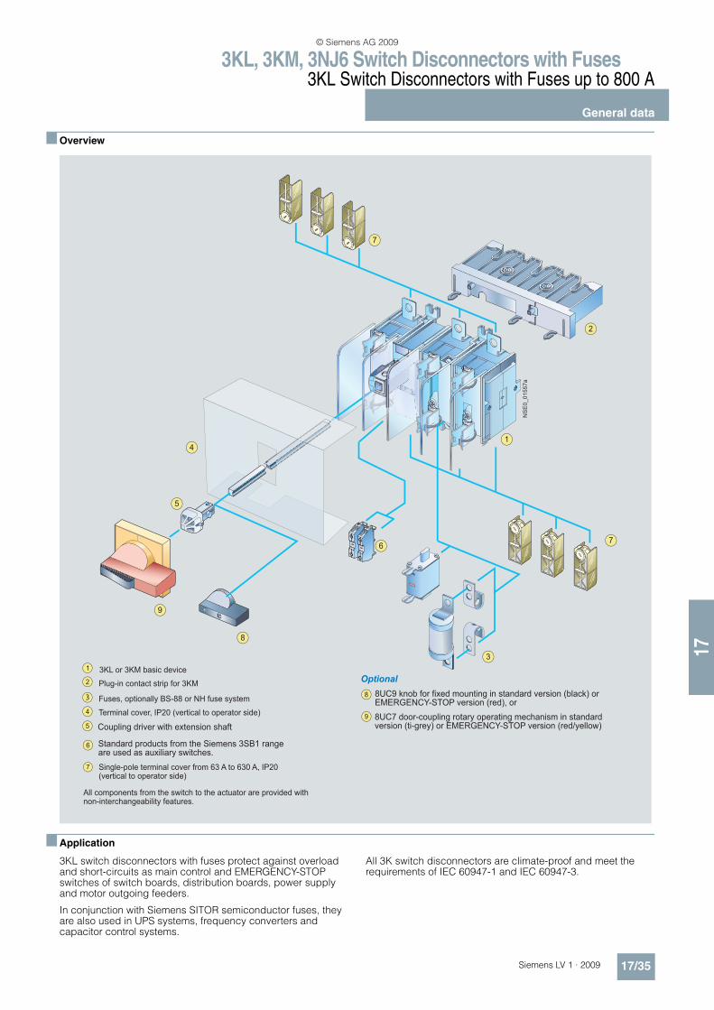
n Overview
n Application
3KL switch disconnectors with fuses protect against overload and short-circuits as main control and EMERGENCY-STOP switches of switch boards, distribution boards, power supply and motor outgoing feeders.
In conjunction with Siemens SITOR semiconductor fuses, they are also used in UPS systems, frequency converters and capacitor control systems.
All 3K switch disconnectors are climate-proof and meet the requirements of IEC 60947-1 and IEC 60947-3.
2
6
5
7
7
3
1
9
9
7
8
4
3
3KL or 3KM basic device
Plug-in contact strip for 3KM
Fuses, optionally BS-88 or NH fuse system
Coupling driver with extension shaft
Single-pole terminal cover from 63 A to 630 A, IP20 (vertical to operator side)
Terminal cover, IP20 (vertical to operator side)
Standard products from the Siemens 3SB1 range are used as auxiliary switches.
8UC9 knob for fixed mounting in standard version (black) or EMERGENCY-STOP version (red), or
8UC7 door-coupling rotary operating mechanism in standard version (ti-grey) or EMERGENCY-STOP version (red/yellow)
Optional
All components from the switch to the actuator are provided with non-interchangeability features.
NSE0_01557a
© Siemens AG 2009
3KL, 3KM, 3NJ6 Switch Disconnectors with Fuses3KL Switch Disconnectors with Fuses up to 800 A
Surface mounting and installation
17/36 Siemens LV 1 · 2009* You can order this quantity or a multiple thereof.
17
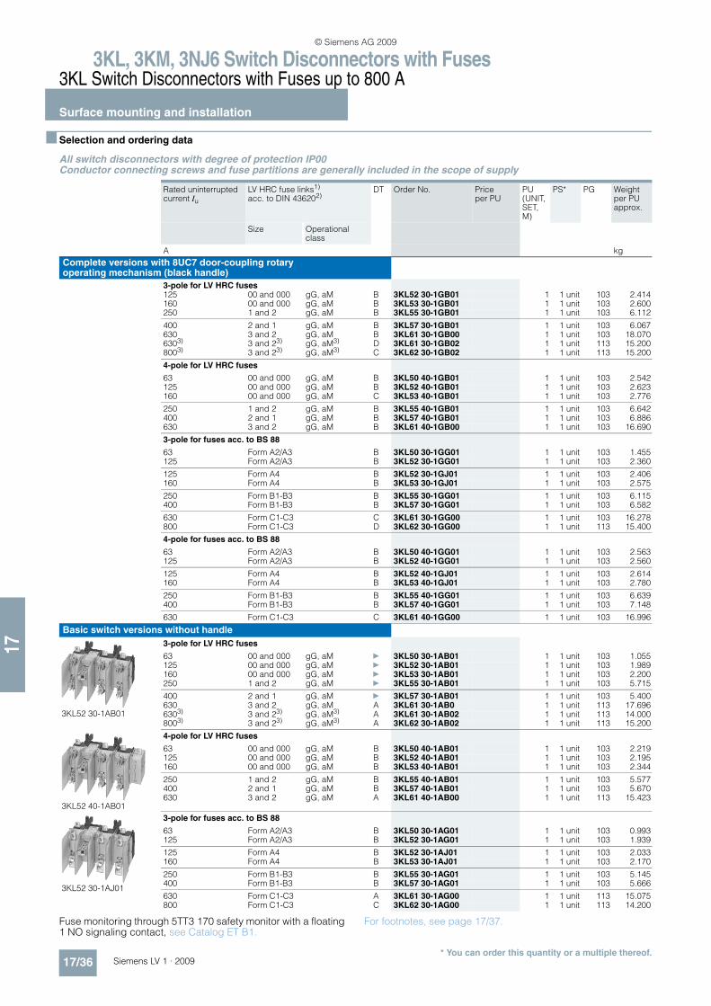
n Selection and ordering data
All switch disconnectors with degree of protection IP00Conductor connecting screws and fuse partitions are generally included in the scope of supply
Fuse monitoring through 5TT3 170 safety monitor with a floating 1 NO signaling contact, see Catalog ET B1.
For footnotes, see page 17/37.
Rated uninterrupted current Iu
LV HRC fuse links1)
acc. to DIN 436202)DT Order No. Price
per PUPU (UNIT, SET, M)
PS* PG Weight per PU approx.
Size Operational class
A kg
Complete versions with 8UC7 door-coupling rotary operating mechanism (black handle)
3-pole for LV HRC fuses125 00 and 000 gG, aM B 3KL52 30-1GB01 1 1 unit 103 2.414160 00 and 000 gG, aM B 3KL53 30-1GB01 1 1 unit 103 2.600250 1 and 2 gG, aM B 3KL55 30-1GB01 1 1 unit 103 6.112
400 2 and 1 gG, aM B 3KL57 30-1GB01 1 1 unit 103 6.067630 3 and 2 gG, aM B 3KL61 30-1GB00 1 1 unit 103 18.0706303) 3 and 23) gG, aM3) D 3KL61 30-1GB02 1 1 unit 113 15.2008003) 3 and 23) gG, aM3) C 3KL62 30-1GB02 1 1 unit 113 15.200
4-pole for LV HRC fuses
63 00 and 000 gG, aM B 3KL50 40-1GB01 1 1 unit 103 2.542125 00 and 000 gG, aM B 3KL52 40-1GB01 1 1 unit 103 2.623160 00 and 000 gG, aM C 3KL53 40-1GB01 1 1 unit 103 2.776
250 1 and 2 gG, aM B 3KL55 40-1GB01 1 1 unit 103 6.642400 2 and 1 gG, aM B 3KL57 40-1GB01 1 1 unit 103 6.886630 3 and 2 gG, aM B 3KL61 40-1GB00 1 1 unit 103 16.690
3-pole for fuses acc. to BS 88
63 Form A2/A3 B 3KL50 30-1GG01 1 1 unit 103 1.455125 Form A2/A3 B 3KL52 30-1GG01 1 1 unit 103 2.360
125 Form A4 B 3KL52 30-1GJ01 1 1 unit 103 2.406160 Form A4 B 3KL53 30-1GJ01 1 1 unit 103 2.575
250 Form B1-B3 B 3KL55 30-1GG01 1 1 unit 103 6.115400 Form B1-B3 B 3KL57 30-1GG01 1 1 unit 103 6.582
630 Form C1-C3 C 3KL61 30-1GG00 1 1 unit 103 16.278800 Form C1-C3 D 3KL62 30-1GG00 1 1 unit 113 15.400
4-pole for fuses acc. to BS 88
63 Form A2/A3 B 3KL50 40-1GG01 1 1 unit 103 2.563125 Form A2/A3 B 3KL52 40-1GG01 1 1 unit 103 2.560
125 Form A4 B 3KL52 40-1GJ01 1 1 unit 103 2.614160 Form A4 B 3KL53 40-1GJ01 1 1 unit 103 2.780
250 Form B1-B3 B 3KL55 40-1GG01 1 1 unit 103 6.639400 Form B1-B3 B 3KL57 40-1GG01 1 1 unit 103 7.148
630 Form C1-C3 C 3KL61 40-1GG00 1 1 unit 103 16.996
Basic switch versions without handle
3KL52 30-1AB01
3-pole for LV HRC fuses
63 00 and 000 gG, aM } 3KL50 30-1AB01 1 1 unit 103 1.055125 00 and 000 gG, aM } 3KL52 30-1AB01 1 1 unit 103 1.989160 00 and 000 gG, aM } 3KL53 30-1AB01 1 1 unit 103 2.200250 1 and 2 gG, aM } 3KL55 30-1AB01 1 1 unit 103 5.715
400 2 and 1 gG, aM } 3KL57 30-1AB01 1 1 unit 103 5.400630 3 and 2 gG, aM A 3KL61 30-1AB0 1 1 unit 113 17.6966303) 3 and 23) gG, aM3) A 3KL61 30-1AB02 1 1 unit 113 14.0008003) 3 and 23) gG, aM3) A 3KL62 30-1AB02 1 1 unit 113 15.200
3KL52 40-1AB01
4-pole for LV HRC fuses
63 00 and 000 gG, aM B 3KL50 40-1AB01 1 1 unit 103 2.219125 00 and 000 gG, aM B 3KL52 40-1AB01 1 1 unit 103 2.195160 00 and 000 gG, aM B 3KL53 40-1AB01 1 1 unit 103 2.344
250 1 and 2 gG, aM B 3KL55 40-1AB01 1 1 unit 103 5.577400 2 and 1 gG, aM B 3KL57 40-1AB01 1 1 unit 103 5.670630 3 and 2 gG, aM A 3KL61 40-1AB00 1 1 unit 113 15.423
3KL52 30-1AJ01
3-pole for fuses acc. to BS 88
63 Form A2/A3 B 3KL50 30-1AG01 1 1 unit 103 0.993125 Form A2/A3 B 3KL52 30-1AG01 1 1 unit 103 1.939
125 Form A4 B 3KL52 30-1AJ01 1 1 unit 103 2.033160 Form A4 B 3KL53 30-1AJ01 1 1 unit 103 2.170
250 Form B1-B3 B 3KL55 30-1AG01 1 1 unit 103 5.145400 Form B1-B3 B 3KL57 30-1AG01 1 1 unit 103 5.666
630 Form C1-C3 A 3KL61 30-1AG00 1 1 unit 113 15.075800 Form C1-C3 C 3KL62 30-1AG00 1 1 unit 113 14.200
© Siemens AG 2009
3KL, 3KM, 3NJ6 Switch Disconnectors with Fuses3KL Switch Disconnectors with Fuses up to 800 A
Surface mounting and installation
17/37Siemens LV 1 · 2009* You can order this quantity or a multiple thereof.
17
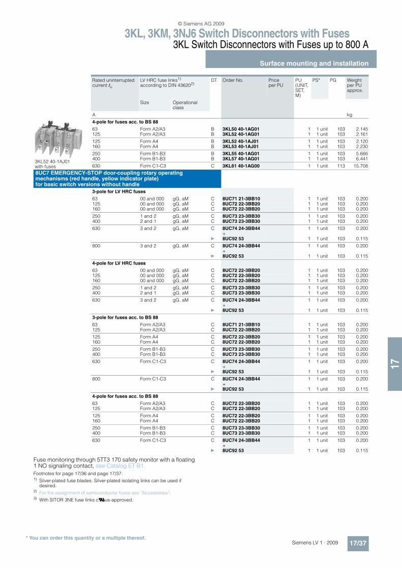
Fuse monitoring through 5TT3 170 safety monitor with a floating 1 NO signaling contact, see Catalog ET B1.
Footnotes for page 17/36 and page 17/37:1) Silver-plated fuse blades. Silver-plated isolating links can be used if
desired.2) For the assignment of semiconductor fuses see "Accessories".3) With SITOR 3NE fuse links cUus-approved.
Rated uninterrupted current Iu
LV HRC fuse links1) according to DIN 436202)
DT Order No. Price per PU
PU (UNIT, SET, M)
PS* PG Weight per PU approx.
Size Operational class
A kg
3KL52 40-1AJ01 with fuses
4-pole for fuses acc. to BS 88
63 Form A2/A3 B 3KL50 40-1AG01 1 1 unit 103 2.145125 Form A2/A3 B 3KL52 40-1AG01 1 1 unit 103 2.161
125 Form A4 B 3KL52 40-1AJ01 1 1 unit 103 2.120160 Form A4 B 3KL53 40-1AJ01 1 1 unit 103 2.230
250 Form B1-B3 B 3KL55 40-1AG01 1 1 unit 103 5.666400 Form B1-B3 B 3KL57 40-1AG01 1 1 unit 103 6.441
630 Form C1-C3 C 3KL61 40-1AG00 1 1 unit 113 15.708
8UC7 EMERGENCY-STOP door-coupling rotary operating mechanisms (red handle, yellow indicator plate) for basic switch versions without handle
3-pole for LV HRC fuses
63 00 and 000 gG, aM C 8UC71 21-3BB10 1 1 unit 103 0.200125 00 and 000 gG, aM C 8UC72 22-3BB20 1 1 unit 103 0.200160 00 and 000 gG, aM C 8UC72 22-3BB20 1 1 unit 103 0.200
250 1 and 2 gG, aM C 8UC73 23-3BB30 1 1 unit 103 0.200400 2 and 1 gG, aM C 8UC73 23-3BB30 1 1 unit 103 0.200
630 3 and 2 gG, aM C 8UC74 24-3BB44 1 1 unit 103 0.200+
} 8UC92 53 1 1 unit 103 0.115
800 3 and 2 gG, aM C 8UC74 24-3BB44 1 1 unit 103 0.200+
} 8UC92 53 1 1 unit 103 0.115
4-pole for LV HRC fuses
63 00 and 000 gG, aM C 8UC72 22-3BB20 1 1 unit 103 0.200125 00 and 000 gG, aM C 8UC72 22-3BB20 1 1 unit 103 0.200160 00 and 000 gG, aM C 8UC72 22-3BB20 1 1 unit 103 0.200
250 1 and 2 gG, aM C 8UC73 23-3BB30 1 1 unit 103 0.200400 2 and 1 gG, aM C 8UC73 23-3BB30 1 1 unit 103 0.200
630 3 and 2 gG, aM C 8UC74 24-3BB44 1 1 unit 103 0.200+
} 8UC92 53 1 1 unit 103 0.115
3-pole for fuses acc. to BS 88
63 Form A2/A3 C 8UC71 21-3BB10 1 1 unit 103 0.200125 Form A2/A3 C 8UC72 22-3BB20 1 1 unit 103 0.200
125 Form A4 C 8UC72 22-3BB20 1 1 unit 103 0.200160 Form A4 C 8UC72 22-3BB20 1 1 unit 103 0.200
250 Form B1-B3 C 8UC73 23-3BB30 1 1 unit 103 0.200400 Form B1-B3 C 8UC73 23-3BB30 1 1 unit 103 0.200
630 Form C1-C3 C 8UC74 24-3BB44 1 1 unit 103 0.200+
} 8UC92 53 1 1 unit 103 0.115
800 Form C1-C3 C 8UC74 24-3BB44 1 1 unit 103 0.200+
} 8UC92 53 1 1 unit 103 0.115
4-pole for fuses acc. to BS 88
63 Form A2/A3 C 8UC72 22-3BB20 1 1 unit 103 0.200125 Form A2/A3 C 8UC72 22-3BB20 1 1 unit 103 0.200
125 Form A4 C 8UC72 22-3BB20 1 1 unit 103 0.200160 Form A4 C 8UC72 22-3BB20 1 1 unit 103 0.200
250 Form B1-B3 C 8UC73 23-3BB30 1 1 unit 103 0.200400 Form B1-B3 C 8UC73 23-3BB30 1 1 unit 103 0.200
630 Form C1-C3 C 8UC74 24-3BB44 1 1 unit 103 0.200+
} 8UC92 53 1 1 unit 103 0.115
© Siemens AG 2009
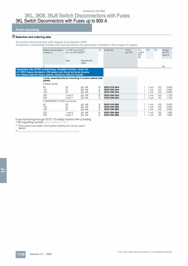
3KL, 3KM, 3NJ6 Switch Disconnectors with Fuses3KL Switch Disconnectors with Fuses up to 800 A
Front mounting
17/38 Siemens LV 1 · 2009* You can order this quantity or a multiple thereof.
17
n Selection and ordering data
All switch disconnectors with degree of protection IP00Conductor connecting screws and fuse partitions are generally included in the scope of supply
Fuse monitoring through 5TT3 170 safety monitor with a floating 1 NO signaling contact, see Catalog ET B1. 1) Silver-plated fuse blades. Silver-plated isolating links can be used if
desired.2) For the assignment of semiconductor fuses see "Accessories".
Rated uninterrupted current Iu
LV HRC fuse links1) acc. to DIN 436202)
DT Order No. Price per PU
PU (UNIT, SET, M)
PS* PG Weight per PU approx.
Size Operational class
A kg
Assembly kits (IP40) comprising: lockable handle, cover forLV HRC fuses (locked in ON state) and three terminal covers for infeed side for basic switch versions without handle
3-pole, assembly kits for mounting in control cabinet side panels
• Black handle
63 00 gG, aM B 3KX3 516-3AA 1 1 unit 103 0.626125 00 gG, aM B 3KX3 526-3AA 1 1 unit 103 0.820160 00 gG, aM B 3KX3 536-3AA 1 1 unit 103 0.880
250 1 and 2 gG, aM B 3KX3 556-3AA 1 1 unit 103 1.720400 2 and 1 gG, aM B 3KX3 556-3AA 1 1 unit 103 1.720
• EMERGENCY-STOP red handle
63 00 gG, aM B 3KX3 516-3BA 1 1 unit 103 0.625125 00 gG, aM B 3KX3 526-3BA 1 1 unit 103 0.846160 00 gG, aM B 3KX3 536-3BA 1 1 unit 103 0.883
250 1 and 2 gG, aM B 3KX3 556-3BA 1 1 unit 103 1.690400 2 and 1 gG, aM B 3KX3 556-3BA 1 1 unit 103 1.690
© Siemens AG 2009

3KL, 3KM, 3NJ6 Switch Disconnectors with Fuses3KL Switch Disconnectors with Fuses up to 800 A
Accessories
17/39Siemens LV 1 · 2009* You can order this quantity or a multiple thereof.
17
n Selection and ordering data
Version DT Order No. Price per PU
PU (UNIT, SET, M)
PS* PG Weight per PU approx.
kg
3KL50 30
3KX3 552-3DA01
Terminal covers
(1 set = 6 units) for 3-pole devices } 3KX3 552-3DA01 1 1 unit 103 0.077
3KX3 5.7-3AA
Fuse covers } 3KX3 517-3AA 1 1 unit 103 0.041(interlock only detachable in the OFF position)
Covers IP20 } 3KX3 507-0CA02 1 1 unit 103 0.400For 3-pole devices
Fuse partitions } 3KX3 507-0AA01 1 1 unit 103 0.044(1 set = 5 units)
3KX3 507-0BA01
Lyre-shaped fuse covers B 3KX3 507-0BA01 1 1 unit 103 0.033(1 set = 6 units)
Door-coupling rotary operating mechanisms IP65Black handle, shaft 300 mm C 8UC71 11-1BB10 1 1 unit 103 0.200
EMERGENCY-STOP (yellow/red), shaft 300 mm C 8UC71 21-3BB10 1 1 unit 103 0.200
Operating mechanisms for fixed mounting } 3KX3 516-1AA 1 1 unit 103 0.088Black handle, shaft 250 mm
Extension shafts, 300 mm long B 8UC60 31 1 1 unit 103 0.068
Extension shafts, 600 mm long B 8UC60 81 1 1 unit 103 0.136
Shaft connecting pieces B 8UC60 21 1 1 unit 103 0.031
3SB14 00-0A
Auxiliary switches C 3SB14 00-0A 1 1 unit 102 0.0201 NO + 1 NC1)
Fuse monitor connections B 3KX3 505-0AA 1 1 unit 103 0.014(1 set = 6 units)
3KL50 40/3KL52/3KL53
3KX3 552-3DA01
Terminal coversFor 3-pole devices (1 set = 6 units)
• 3KL52 } 3KX3 552-3DA01 1 1 unit 103 0.077
• 3KL53 } 3KX3 553-3DA01 1 1 unit 103 0.147
For 4-pole devices (1 set = 8 units)
• 3KL50 40, 3KL52 B 3KX3 552-3DB01 1 1 unit 103 0.102
• 3KL53 B 3KX3 553-3DB01 1 1 unit 103 0.170
3KX3 5.7-3AA
Fuse covers2)
(interlock only detachable in the OFF position)} 3KX3 527-3AA 1 1 unit 103 0.071
Covers IP20 } 3KX3 527-0CA02 1 1 unit 103 0.765For 3KL52 3-pole devices
Covers IP20 } 3KX3 537-0CA02 1 1 unit 103 0.765For 3KL53 3-pole devices
Fuse partitions } 3KX3 507-0AA01 1 1 unit 103 0.044(1 set = 5 units)
3KX3 507-0BA01
Lyre-shaped fuse covers B 3KX3 507-0BA01 1 1 unit 103 0.033(1 set = 6 units)
1) For more 3SB14 00-0. contact blocks with other contact types, see "Pushbutton Units and Indicator Lights".
2) For 3KX3 527-3AA: Not suitable for use with type A4 BS fuses.
© Siemens AG 2009

3KL, 3KM, 3NJ6 Switch Disconnectors with Fuses3KL Switch Disconnectors with Fuses up to 800 A
Accessories
17/40 Siemens LV 1 · 2009* You can order this quantity or a multiple thereof.
17
Version DT Order No. Price per PU
PU (UNIT, SET, M)
PS* PG Weight per PU approx.
kg
Door-coupling rotary operating mechanisms IP65 Black handle, shaft 300 mm C 8UC72 12-1BB20 1 1 unit 103 0.200
EMERGENCY-STOP (yellow/red), shaft 300 mm C 8UC72 22-3BB20 1 1 unit 103 0.200
Operating mechanisms for fixed mounting } 3KX3 536-1AA 1 1 unit 103 0.155Black handle, shaft 250 mm
Extension shafts, 300 mm long B 8UC60 32 1 1 unit 103 0.132
Extension shafts, 600 mm long B 8UC60 82 1 1 unit 103 0.265
3SB14 00-0A
Shaft connecting pieces B 8UC60 22 1 1 unit 103 0.023
Auxiliary switches C 3SB14 00-0A 1 1 unit 102 0.0201 NO + 1 NC1)
20 ms leading B 3KX3 552-3EA01 1 1 unit 103 0.0191 NO + 1 NC
Fuse monitor connections B 3KX3 505-0AA 1 1 unit 103 0.014(1 set = 6 units)
3KL55/3KL57
Terminal coversFor 3-pole devices (1 set = 6 units) } 3KX3 557-3DA01 1 1 unit 103 0.277For 4-pole devices (1 set = 8 units) B 3KX3 557-3DB01 1 1 unit 103 0.362
3KX3 5.7-3AA
Fuse covers } 3KX3 557-3AA 1 1 unit 103 0.212(interlock only detachable in the OFF position)
Covers IP20 } 3KX3 557-0CA02 1 1 unit 103 1.235For 3-pole devices
Fuse partitions } 3KX3 557-0AA01 1 1 unit 103 0.162(1 set = 5 units)
Door-coupling rotary operating mechanisms IP65 Black handle, shaft 300 mm C 8UC73 13-1BB30 1 1 unit 103 0.200
EMERGENCY-STOP (yellow/red), shaft 300 mm C 8UC73 23-3BB30 1 1 unit 103 0.200
3KX3 176-1E
Operating mechanisms for fixed mounting, size 3 } 3KX3 176-1E 1 1 unit 103 0.285Black handle, shaft 250 mm
Extension shafts, 300 mm long C 8UC60 33 1 1 unit 103 0.217
Extension shafts, 600 mm long B 8UC60 83 1 1 unit 103 0.430
Shaft connecting pieces B 8UC60 23 1 1 unit 103 0.085
Auxiliary switches
3SB14 00-0A
1 NO + 1 NC1) C 3SB14 00-0A 1 1 unit 102 0.020
20 ms leading1 NO + 1 NC B 3KX3 552-3EA01 1 1 unit 103 0.019
Fuse monitor connections B 3KX3 505-0AA 1 1 unit 103 0.014(1 set = 6 units)
1) For more 3SB14 00-0. contact blocks with other contact types, see "Pushbutton Units and Indicator Lights".
© Siemens AG 2009
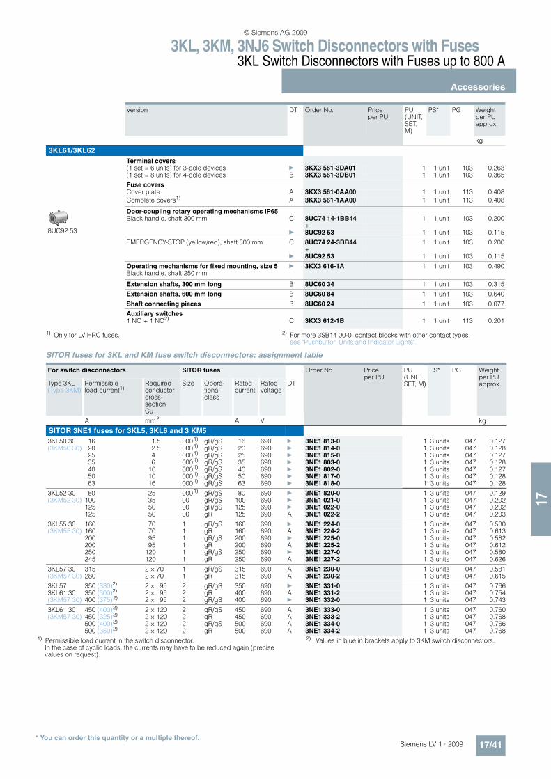
3KL, 3KM, 3NJ6 Switch Disconnectors with Fuses3KL Switch Disconnectors with Fuses up to 800 A
Accessories
17/41Siemens LV 1 · 2009* You can order this quantity or a multiple thereof.
17
1) Only for LV HRC fuses. 2) For more 3SB14 00-0. contact blocks with other contact types, see "Pushbutton Units and Indicator Lights".
SITOR fuses for 3KL and KM fuse switch disconnectors: assignment table
Version DT Order No. Price per PU
PU (UNIT, SET, M)
PS* PG Weight per PU approx.
kg
3KL61/3KL62
Terminal covers
(1 set = 6 units) for 3-pole devices } 3KX3 561-3DA01 1 1 unit 103 0.263(1 set = 8 units) for 4-pole devices B 3KX3 561-3DB01 1 1 unit 103 0.365
Fuse coversCover plate A 3KX3 561-0AA00 1 1 unit 113 0.408
Complete covers1) A 3KX3 561-1AA00 1 1 unit 113 0.408
8UC92 53
Door-coupling rotary operating mechanisms IP65Black handle, shaft 300 mm C 8UC74 14-1BB44 1 1 unit 103 0.200
+} 8UC92 53 1 1 unit 103 0.115
EMERGENCY-STOP (yellow/red), shaft 300 mm C 8UC74 24-3BB44 1 1 unit 103 0.200+
} 8UC92 53 1 1 unit 103 0.115
Operating mechanisms for fixed mounting, size 5 } 3KX3 616-1A 1 1 unit 103 0.490Black handle, shaft 250 mm
Extension shafts, 300 mm long B 8UC60 34 1 1 unit 103 0.315
Extension shafts, 600 mm long B 8UC60 84 1 1 unit 103 0.640
Shaft connecting pieces B 8UC60 24 1 1 unit 103 0.077
Auxiliary switches1 NO + 1 NC2) C 3KX3 612-1B 1 1 unit 113 0.201
For switch disconnectors SITOR fuses Order No. Price per PU
PU (UNIT, SET, M)
PS* PG Weight per PU approx.Type 3KL
(Type 3KM)Permissible load current1)
Required conductor cross-section Cu
Size Opera-tional class
Rated current
Rated voltage
DT
A mm2 A V kg
SITOR 3NE1 fuses for 3KL5, 3KL6 and 3 KM5
3KL50 30 16 1.5 0001) gR/gS 16 690 } 3NE1 813-0 1 3 units 047 0.127(3KM50 30) 20 2.5 0001) gR/gS 20 690 } 3NE1 814-0 1 3 units 047 0.128
25 4 0001) gR/gS 25 690 } 3NE1 815-0 1 3 units 047 0.12735 6 0001) gR/gS 35 690 } 3NE1 803-0 1 3 units 047 0.12840 10 0001) gR/gS 40 690 } 3NE1 802-0 1 3 units 047 0.12750 10 0001) gR/gS 50 690 } 3NE1 817-0 1 3 units 047 0.12863 16 0001) gR/gS 63 690 } 3NE1 818-0 1 3 units 047 0.128
3KL52 30 80 25 0001) gR/gS 80 690 } 3NE1 820-0 1 3 units 047 0.129(3KM52 30) 100 35 00 gR/gS 100 690 } 3NE1 021-0 1 3 units 047 0.202
125 50 00 gR/gS 125 690 } 3NE1 022-0 1 3 units 047 0.202125 50 00 gR 125 690 A 3NE1 022-2 1 3 units 047 0.203
3KL55 30 160 70 1 gR/gS 160 690 } 3NE1 224-0 1 3 units 047 0.580(3KM55 30) 160 70 1 gR 160 690 A 3NE1 224-2 1 3 units 047 0.613
200 95 1 gR/gS 200 690 } 3NE1 225-0 1 3 units 047 0.582200 95 1 gR 200 690 A 3NE1 225-2 1 3 units 047 0.612250 120 1 gR/gS 250 690 } 3NE1 227-0 1 3 units 047 0.580245 120 1 gR 250 690 A 3NE1 227-2 1 3 units 047 0.626
3KL57 30 315 2 × 70 1 gR/gS 315 690 A 3NE1 230-0 1 3 units 047 0.581(3KM57 30) 280 2 × 70 1 gR 315 690 A 3NE1 230-2 1 3 units 047 0.615
3KL57 350 (330)2) 2 × 95 2 gR/gS 350 690 } 3NE1 331-0 1 3 units 047 0.7663KL61 30 350 (300)2) 2 × 95 2 gR 400 690 A 3NE1 331-2 1 3 units 047 0.754(3KM57 30) 400 (375)2) 2 × 95 2 gR/gS 400 690 } 3NE1 332-0 1 3 units 047 0.743
3KL61 30 450 (400)2) 2 × 120 2 gR/gS 450 690 A 3NE1 333-0 1 3 units 047 0.760(3KM57 30) 450 (325)2) 2 × 120 2 gR 450 690 A 3NE1 333-2 1 3 units 047 0.768
500 (400)2) 2 × 120 2 gR/gS 500 690 A 3NE1 334-0 1 3 units 047 0.766500 (350)2) 2 × 120 2 gR 500 690 A 3NE1 334-2 1 3 units 047 0.768
1) Permissible load current in the switch disconnector.In the case of cyclic loads, the currents may have to be reduced again (precise values on request).
2) Values in blue in brackets apply to 3KM switch disconnectors.
© Siemens AG 2009

3KL, 3KM, 3NJ6 Switch Disconnectors with Fuses3KL Switch Disconnectors with Fuses up to 800 A
Accessories
17/42 Siemens LV 1 · 2009* You can order this quantity or a multiple thereof.
17
For technical specifications and dimensional drawings of the SITOR fuses see Catalog ET B1.
For switch disconnectors SITOR fuses Order No. Price per PU
PU (UNIT, SET, M)
PS* PG Weight per PU approx.
Type 3KL(Type 3KM)
Permissible load current1)
Required conductor cross-section Cu
Size Opera-tional class
Rated current
Rated voltage
DT
A mm2 A V kg
630 (710)3) 2 x (40 x 5) 3 gR/gS 710 690 A 3NE1 437-0 1 3 units 047 1.117630 (710)3) 2 x (40 x 5) 3 gR 710 600 D 3NE1 437-1 1 3 units 047 1.120630 (700)3) 2 x (40 x 5) 3 gR 710 690 B 3NE1 437-2 1 3 units 047 1.153630 (800)3) 2 x (50 x 5) 3 gR/gS 800 690 A 3NE1 438-0 1 3 units 047 1.124630 (800)3) 2 x (50 x 5) 3 gR 800 600 B 3NE1 438-1 1 3 units 047 1.113630 (760)3) 2 x (50 x 5) gR 800 690 A 3NE1 438-2 1 3 units 047 1.184
3KL61 30 630 (670)3) 2 x (40 x 5) 3 gR 670 690 A 3NE1 447-2 1 3 units 047 1.170(3KL62) 630 (790)3) 2 x (40 x 8) 3 gR 850 690 A 3NE1 448-2 1 3 units 047 1.207
SITOR 3NE3 ... 3NE8, 3NC2 fuses for 3KL5, 3KL6 and 3KM5
3KL50 25 4 00 gR 25 690 } 3NE8 015-1 1 3 units 047 0.205(3KM50) 33 6 00 gR 35 690 } 3NE8 003-1 1 3 units 047 0.204
45 10 00 gR 50 690 } 3NE8 017-1 1 3 units 047 0.20354 16 00 gR 63 690 } 3NE8 018-1 1 3 units 047 0.205
3KL52 68 25 00 aR 80 690 } 3NE8 020-1 1 3 units 047 0.203(3KM52) 89 35 00 aR 100 690 } 3NE8 021-1 1 3 units 047 0.205
106 50 00 aR 125 690 } 3NE8 022-1 1 3 units 047 0.213130 70 00 aR 160 690 } 3NE8 024-1 1 3 units 047 0.207
3KL552) 32 6 0 gR 32 1000 } 3NE4 101 1 3 units 047 0.278(3KM55)2) 40 10 0 gR 40 1000 } 3NE4 102 1 3 units 047 0.277
50 10 0 gR 50 1000 } 3NE4 117 1 3 units 047 0.27663 16 0 gR 63 1000 } 3NE4 118 1 3 units 047 0.279
80 25 0 aR 80 1000 } 3NE4 120 1 3 units 047 0.27695 35 0 aR 100 1000 } 3NE4 121 1 3 units 047 0.278
120 50 0 aR 125 1000 } 3NE4 122 1 3 units 047 0.279150 70 0 aR 160 1000 } 3NE4 124 1 3 units 047 0.279
90 35 1 aR 100 1000 A 3NE3 221 1 3 units 047 0.580110 50 1 aR 125 1000 A 3NE3 222 1 3 units 047 0.568140 70 1 aR 160 1000 } 3NE3 224 1 3 units 047 0.573175 95 1 aR 200 1000 } 3NE3 225 1 3 units 047 0.570210 120 1 aR 250 1000 } 3NE3 227 1 3 units 047 0.580
3KL57 240 185 1 aR 315 1000 } 3NE3 230-0B 1 3 units 047 0.585(3KM57) 265 240 1 aR 350 1000 A 3NE3 231 1 3 units 047 0.590
290 240 1 aR 400 1000 A 3NE3 232-0B 1 3 units 047 0.576320 2 × 150 1 aR 450 1000 } 3NE3 233 1 3 units 047 0.720
3KL61 340 (360)3) (290)4) 240 2 aR 400 1000 A 3NE3 332-0B 1 3 units 047 0.759(3KL62) 380 (400)3) (320)4) 2 × 150 2 aR 450 1000 A 3NE3 333 1 3 units 047 0.748(3KM57) 440 (470)3) (360)4) 2 × 150 2 aR 500 1000 } 3NE3 334-0B 1 3 units 047 0.753
500 (530)3) (400)4) 2 × 185 2 aR 560 1000 } 3NE3 335 1 3 units 047 0.756540 (580)3) (400)4) 2 × 185 2 aR 630 1000 } 3NE3 336 1 3 units 047 0.760
600 (640)3) (400)4) 2 × 200 2 aR 710 900 } 3NE3 337-8 1 3 units 047 0.762630 (720)3) (400)4) 2 × 200 2 aR 800 800 } 3NE3 338-8 1 3 units 047 0.764630 (800)3) (400)4) 2 × 200 2 aR 900 690 } 3NE3 340-8 1 3 units 047 0.753
200 (200)3) (175)4) 120 2 aR 250 800 } 3NE4 327-0B 1 3 units 047 0.753260 (260)3) (230)4) 240 2 aR 315 800 } 3NE4 330-0B 1 3 units 047 0.760370 (370)3) (340)4) 2 x (30 x 5) 2 aR 450 800 } 3NE4 333-0B 1 3 units 047 0.760425 (450)3) (380)4) 2 x (30 x 5) 2 aR 500 800 } 3NE4 334-0B 1 3 units 047 0.754600 (630)3) (400)4) 2 x (40 x 5) 2 aR 710 800 } 3NE4 337 1 3 units 047 0.771
3KL61 145 (150)3) 70 3 gR 150 500 B 3NC2 423-3C 1 3 units 047 0.940(3KL62) 180 (190)3) 95 3 gR 200 500 B 3NC2 425-3 1 3 units 047 1.057
225 (240)3) 120 3 gR 250 500 B 3NC2 427-3 1 3 units 047 1.066255 (270)3) 185 3 gR 300 500 B 3NC2 428-3 1 3 units 047 1.078330 (345)3) 240 3 gR 350 500 B 3NC2 431-3C 1 3 units 047 0.940400 (400)3) 240 3 gR 400 500 B 3NC2 432-3C 1 3 units 047 0.940
135 (140)3) 70 3 gR 150 660 B 3NC8 423-3 1 3 units 047 1.062180 (190)3) 95 3 gR 200 660 B 3NC8 425-3 1 3 units 047 1.063225 (240)3) 120 3 gR 250 660 B 3NC8 427-3 1 3 units 047 1.069300 (315)3) 240 3 gR 350 660 B 3NC8 431-3 1 3 units 047 1.072425 (450)3) 2 × 150 3 gR 500 660 B 3NC8 434-3 1 3 units 047 1.069
630 (800)3) 2 × (60 x 6) 3 aR 1000 600 C 3NC8 444-3 1 3 units 047 1.0851) Permissible load current in the switch disconnector.
In the case of cyclic loads, the currents may have to be reduced again (precise values on request).
2) Due to the mechanical stress on the relatively long fuse blades, SITOR 3NE41 fuses should be switchable only occasionally and only at zero current.
3) Values in black in brackets apply to 3KL62 switch disconnectors.4) Values in blue in brackets apply to 3KM switch disconnectors.
© Siemens AG 2009

3KL, 3KM, 3NJ6 Switch Disconnectors with Fuses3KM Switch Disconnectors with Fuses and Isolating Plug Connectors up to 400 A
General data
17/43Siemens LV 1 · 2009
17
n Overview
n Application
3KM switch disconnectors with fuses protect against overload and short-circuits as main control and EMERGENCY-STOP switches of switch boards, distribution boards, power supply and motor outgoing feeders.
In conjunction with Siemens SITOR semiconductor fuses, they are also used in UPS systems, frequency converters and capac-itor control systems.
All 3K switch disconnectors are climate-proof and meet the re-quirements of IEC 60947-1 and IEC 60947-3.
2
6
5
7
7
3
1
9
9
7
8
4
3
3KL or 3KM basic device
Plug-in contact strip for 3KM
Fuses, optionally BS-88 or NH fuse system
Coupling driver with extension shaft
Single-pole terminal cover from 63 A to 630 A, IP20 (vertical to operator side)
Terminal cover, IP20 (vertical to operator side)
Standard products from the Siemens 3SB1 range are used as auxiliary switches.
8UC9 knob for fixed mounting in standard version (black) or EMERGENCY-STOP version (red), or
8UC7 door-coupling rotary operating mechanism in standard version (ti-grey) or EMERGENCY-STOP version (red/yellow)
Optional
All components from the switch to the actuator are provided with non-interchangeability features.
NSE0_01557a
© Siemens AG 2009
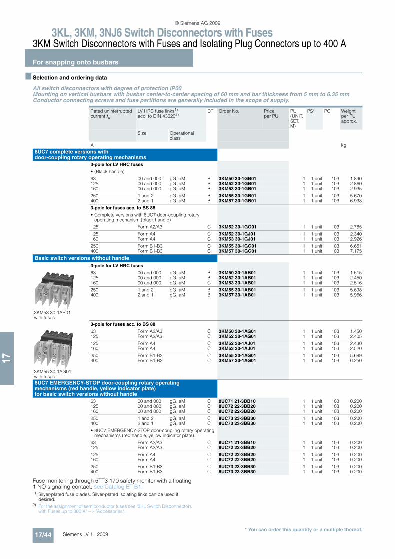
3KL, 3KM, 3NJ6 Switch Disconnectors with Fuses3KM Switch Disconnectors with Fuses and Isolating Plug Connectors up to 400 A
For snapping onto busbars
17/44 Siemens LV 1 · 2009* You can order this quantity or a multiple thereof.
17
n Selection and ordering data
All switch disconnectors with degree of protection IP00Mounting on vertical busbars with busbar center-to-center spacing of 60 mm and bar thickness from 5 mm to 6.35 mmConductor connecting screws and fuse partitions are generally included in the scope of supply.
Fuse monitoring through 5TT3 170 safety monitor with a floating 1 NO signaling contact, see Catalog ET B1. 1) Silver-plated fuse blades. Silver-plated isolating links can be used if
desired.2) For the assignment of semiconductor fuses see "3KL Switch Disconnectors
with Fuses up to 800 A" --> "Accessories".
Rated uninterrupted current Iu
LV HRC fuse links1) acc. to DIN 436202)
DT Order No. Price per PU
PU (UNIT, SET, M)
PS* PG Weight per PU approx.
Size Operational class
A kg
8UC7 complete versions with door-coupling rotary operating mechanisms
3-pole for LV HRC fuses
• (Black handle)
63 00 and 000 gG, aM B 3KM50 30-1GB01 1 1 unit 103 1.890125 00 and 000 gG, aM B 3KM52 30-1GB01 1 1 unit 103 2.860160 00 and 000 gG, aM B 3KM53 30-1GB01 1 1 unit 103 2.935
250 1 and 2 gG, aM B 3KM55 30-1GB01 1 1 unit 103 5.670400 2 and 1 gG, aM B 3KM57 30-1GB01 1 1 unit 103 6.938
3-pole for fuses acc. to BS 88
• Complete versions with 8UC7 door-coupling rotary operating mechanism (black handle)
125 Form A2/A3 C 3KM52 30-1GG01 1 1 unit 103 2.785
125 Form A4 C 3KM52 30-1GJ01 1 1 unit 103 2.340160 Form A4 C 3KM53 30-1GJ01 1 1 unit 103 2.926
250 Form B1-B3 C 3KM55 30-1GG01 1 1 unit 103 6.651400 Form B1-B3 C 3KM57 30-1GG01 1 1 unit 103 7.175
Basic switch versions without handle
3-pole for LV HRC fuses
3KM53 30-1AB01 with fuses
63 00 and 000 gG, aM B 3KM50 30-1AB01 1 1 unit 103 1.515125 00 and 000 gG, aM B 3KM52 30-1AB01 1 1 unit 103 2.450160 00 and 000 gG, aM C 3KM53 30-1AB01 1 1 unit 103 2.516
250 1 and 2 gG, aM B 3KM55 30-1AB01 1 1 unit 103 5.698400 2 and 1 gG, aM B 3KM57 30-1AB01 1 1 unit 103 5.966
3-pole for fuses acc. to BS 88
3KM55 30-1AG01 with fuses
63 Form A2/A3 C 3KM50 30-1AG01 1 1 unit 103 1.450125 Form A2/A3 C 3KM52 30-1AG01 1 1 unit 103 2.405
125 Form A4 C 3KM52 30-1AJ01 1 1 unit 103 2.430160 Form A4 C 3KM53 30-1AJ01 1 1 unit 103 2.520
250 Form B1-B3 C 3KM55 30-1AG01 1 1 unit 103 5.689400 Form B1-B3 C 3KM57 30-1AG01 1 1 unit 103 6.250
8UC7 EMERGENCY-STOP door-coupling rotary operating mechanisms (red handle, yellow indicator plate) for basic switch versions without handle
63 00 and 000 gG, aM C 8UC71 21-3BB10 1 1 unit 103 0.200125 00 and 000 gG, aM C 8UC72 22-3BB20 1 1 unit 103 0.200160 00 and 000 gG, aM C 8UC72 22-3BB20 1 1 unit 103 0.200
250 1 and 2 gG, aM C 8UC73 23-3BB30 1 1 unit 103 0.200400 2 and 1 gG, aM C 8UC73 23-3BB30 1 1 unit 103 0.200
• 8UC7 EMERGENCY-STOP door-coupling rotary operating mechanisms (red handle, yellow indicator plate)
63 Form A2/A3 C 8UC71 21-3BB10 1 1 unit 103 0.200125 Form A2/A3 C 8UC72 22-3BB20 1 1 unit 103 0.200
125 Form A4 C 8UC72 22-3BB20 1 1 unit 103 0.200160 Form A4 C 8UC72 22-3BB20 1 1 unit 103 0.200
250 Form B1-B3 C 8UC73 23-3BB30 1 1 unit 103 0.200400 Form B1-B3 C 8UC73 23-3BB30 1 1 unit 103 0.200
© Siemens AG 2009
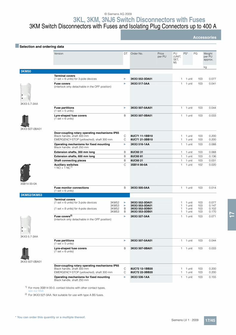
3KL, 3KM, 3NJ6 Switch Disconnectors with Fuses3KM Switch Disconnectors with Fuses and Isolating Plug Connectors up to 400 A
Accessories
17/45Siemens LV 1 · 2009* You can order this quantity or a multiple thereof.
17
n Selection and ordering data
Version DT Order No. Price per PU
PU (UNIT, SET, M)
PS* PG Weight per PU approx.
kg
3KM50
Terminal covers(1 set = 6 units) for 3-pole devices } 3KX3 552-3DA01 1 1 unit 103 0.077
3KX3 5.7-3AA
Fuse covers } 3KX3 517-3AA 1 1 unit 103 0.041(interlock only detachable in the OFF position)
Fuse partitions } 3KX3 507-0AA01 1 1 unit 103 0.044(1 set = 5 units)
3KX3 507-0BA01
Lyre-shaped fuse covers B 3KX3 507-0BA01 1 1 unit 103 0.033(1 set = 6 units)
Door-coupling rotary operating mechanisms IP65Black handle, shaft 300 mm C 8UC71 11-1BB10 1 1 unit 103 0.200
EMERGENCY-STOP (yellow/red), shaft 300 mm C 8UC71 21-3BB10 1 1 unit 103 0.200
Operating mechanisms for fixed mounting } 3KX3 516-1AA 1 1 unit 103 0.088Black handle, shaft 250 mm
Extension shafts, 300 mm long B 8UC60 31 1 1 unit 103 0.068
Extension shafts, 600 mm long B 8UC60 81 1 1 unit 103 0.136
Shaft connecting pieces B 8UC60 21 1 1 unit 103 0.031
3SB14 00-0A
Auxiliary switches C 3SB14 00-0A 1 1 unit 102 0.0201 NO + 1 NC1)
Fuse monitor connections B 3KX3 505-0AA 1 1 unit 103 0.014(1 set = 6 units)
3KM52/3KM53
Terminal covers(1 set = 6 units) for 3-pole devices 3KM52 } 3KX3 552-3DA01 1 1 unit 103 0.077
3KM53 } 3KX3 553-3DA01 1 1 unit 103 0.147(1 set = 8 units) for 4-pole devices 3KM52 B 3KX3 552-3DB01 1 1 unit 103 0.102
3KM53 B 3KX3 553-3DB01 1 1 unit 103 0.170
3KX3 5.7-3AA
Fuse covers2)} 3KX3 527-3AA 1 1 unit 103 0.071
(interlock only detachable in the OFF position)
Fuse partitions } 3KX3 507-0AA01 1 1 unit 103 0.044(1 set = 5 units)
3KX3 507-0BA01
Lyre-shaped fuse covers B 3KX3 507-0BA01 1 1 unit 103 0.033(1 set = 6 units)
Door-coupling rotary operating mechanisms IP65 Black handle, shaft 300 mm C 8UC72 12-1BB20 1 1 unit 103 0.200
EMERGENCY-STOP (yellow/red), shaft 300 mm C 8UC72 22-3BB20 1 1 unit 103 0.200
Operating mechanisms for fixed mounting } 3KX3 536-1AA 1 1 unit 103 0.155Black handle, shaft 250 mm
1) For more 3SB14 00-0. contact blocks with other contact types, see our Mall.
2) For 3KX3 527-3AA: Not suitable for use with type A BS fuses.
© Siemens AG 2009
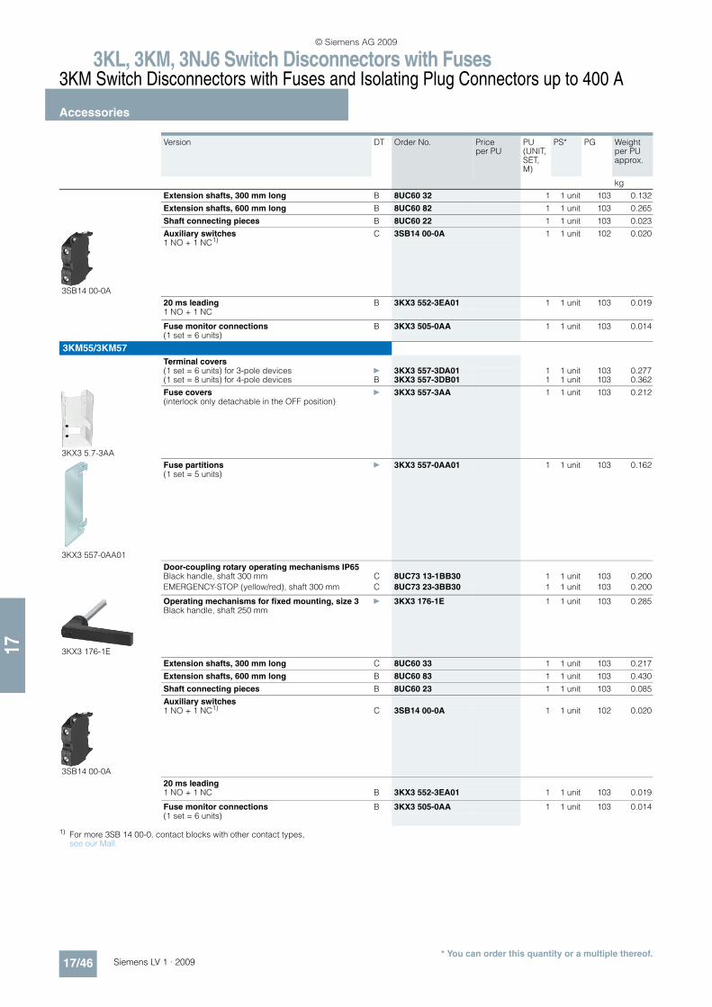
3KL, 3KM, 3NJ6 Switch Disconnectors with Fuses3KM Switch Disconnectors with Fuses and Isolating Plug Connectors up to 400 A
Accessories
17/46 Siemens LV 1 · 2009* You can order this quantity or a multiple thereof.
17
1) For more 3SB 14 00-0. contact blocks with other contact types, see our Mall.
Version DT Order No. Price per PU
PU (UNIT, SET, M)
PS* PG Weight per PU approx.
kg
Extension shafts, 300 mm long B 8UC60 32 1 1 unit 103 0.132
Extension shafts, 600 mm long B 8UC60 82 1 1 unit 103 0.265
Shaft connecting pieces B 8UC60 22 1 1 unit 103 0.023
3SB14 00-0A
Auxiliary switches C 3SB14 00-0A 1 1 unit 102 0.0201 NO + 1 NC1)
20 ms leading B 3KX3 552-3EA01 1 1 unit 103 0.0191 NO + 1 NC
Fuse monitor connections B 3KX3 505-0AA 1 1 unit 103 0.014(1 set = 6 units)
3KM55/3KM57
Terminal covers(1 set = 6 units) for 3-pole devices } 3KX3 557-3DA01 1 1 unit 103 0.277(1 set = 8 units) for 4-pole devices B 3KX3 557-3DB01 1 1 unit 103 0.362
3KX3 5.7-3AA
Fuse covers } 3KX3 557-3AA 1 1 unit 103 0.212(interlock only detachable in the OFF position)
3KX3 557-0AA01
Fuse partitions } 3KX3 557-0AA01 1 1 unit 103 0.162(1 set = 5 units)
Door-coupling rotary operating mechanisms IP65Black handle, shaft 300 mm C 8UC73 13-1BB30 1 1 unit 103 0.200
EMERGENCY-STOP (yellow/red), shaft 300 mm C 8UC73 23-3BB30 1 1 unit 103 0.200
3KX3 176-1E
Operating mechanisms for fixed mounting, size 3 } 3KX3 176-1E 1 1 unit 103 0.285Black handle, shaft 250 mm
Extension shafts, 300 mm long C 8UC60 33 1 1 unit 103 0.217
Extension shafts, 600 mm long B 8UC60 83 1 1 unit 103 0.430
Shaft connecting pieces B 8UC60 23 1 1 unit 103 0.085
Auxiliary switches
3SB14 00-0A
1 NO + 1 NC1) C 3SB14 00-0A 1 1 unit 102 0.020
20 ms leading1 NO + 1 NC B 3KX3 552-3EA01 1 1 unit 103 0.019
Fuse monitor connections B 3KX3 505-0AA 1 1 unit 103 0.014(1 set = 6 units)
© Siemens AG 2009

17
3KL, 3KM, 3NJ6 Switch Disconnectors with Fuses8UC Door-Coupling Rotary Operating Mechanisms
For 3K switch disconnectors
17/47Siemens LV 1 · 2009
n Overview
4 standard sizes of operating mechanisms are available:
1) Operating mechanisms tested with triple torque (according to EN 60947-3). They are therefore qualified for use in all controls, especially for disconnectors.
2) Operation with two hands.
n Application
8UC7 door-coupling rotary operating mechanisms can be used in electrical controls, distribution and switchboards in cases where switches have to be mounted behind covers, end plates and doors that must be opened and where they are to be oper-ated manually from outside.
Operating conditions and ambient conditions
The temperature range for operation of the rotary operating mechanisms is between -25 °C and +60 °C.
Thanks to the use of glass fiber-reinforced molded plastic for handles and masking plates as well as metal components with surface protection, the rotary operating mechanisms are suit-able for rough conditions, high air humidity and aggressive atmospheres.
Degree of protection
Degree of protection when installed is IP65.
Protective measures
All rotary operating mechanisms are fully insulated.
Standards
8UC7 door-coupling rotary operating mechanisms are in line with the following standards:
Size Rated torque1) Shaft profile Masking plate
Nm mm x mm mm x mm
1 4 6 x 6 75 x 75
2 9 8 x 8 75 x 75
3 25 10 x 10 or 12 x 12
100 x 100
4 40/552) 12 x 12 100 x 100
IEC 60204-1, EN 60204-1 (VDE 0113 Part 1)
Electrical equipment of machines
IEC 60439-1, EN 60439-1 (VDE 0660 Part 500)
Low-voltage switchgear and controlgear assemblies
IEC 60947-3, EN 60947-3 (VDE 0660 Part 107)
Low-voltage switchgear and controlgear; switches, disconnec-tors, switch disconnectors and fuse-combination units
© Siemens AG 2009
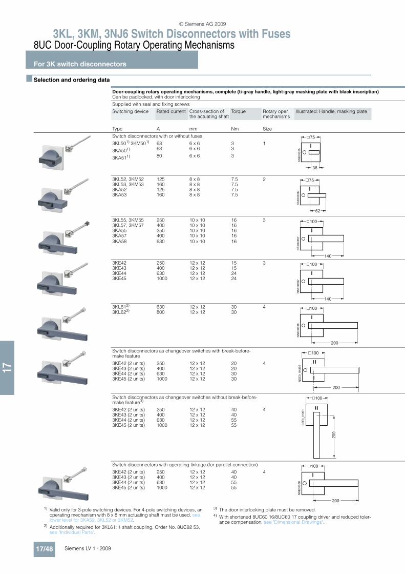
3KL, 3KM, 3NJ6 Switch Disconnectors with Fuses 8UC Door-Coupling Rotary Operating Mechanisms
For 3K switch disconnectors
17/48 Siemens LV 1 · 2009
17
n Selection and ordering data
Door-coupling rotary operating mechanisms, complete (ti-gray handle, light-gray masking plate with black inscription)Can be padlocked, with door interlocking
Supplied with seal and fixing screws
Switching device Rated current Cross-section of the actuating shaft
Torque Rotary oper. mechanisms
Illustrated: Handle, masking plate
Type A mm Nm Size
Switch disconnectors with or without fuses
3KL501) 3KM501) 63 6 x 6 3 1
3KA501) 63 6 x 6 3
3KA511) 80 6 x 6 3
3KL52, 3KM52 125 8 x 8 7.5 2
3KL53, 3KM53 160 8 x 8 7.53KA52 125 8 x 8 7.53KA53 160 8 x 8 7.5
3KL55, 3KM55 250 10 x 10 16 3
3KL57, 3KM57 400 10 x 10 163KA55 250 10 x 10 163KA57 400 10 x 10 16
3KA58 630 10 x 10 16
3KE42 250 12 x 12 15 3
3KE43 400 12 x 12 153KE44 630 12 x 12 243KE45 1000 12 x 12 24
3KL612) 630 12 x 12 30 4
3KL622) 800 12 x 12 30
Switch disconnectors as changeover switches with break-before-make feature
3KE42 (2 units) 250 12 x 12 20 43KE43 (2 units) 400 12 x 12 203KE44 (2 units) 630 12 x 12 303KE45 (2 units) 1000 12 x 12 30
Switch disconnectors as changeover switches without break-before-make feature3)
3KE42 (2 units) 250 12 x 12 40 43KE43 (2 units) 400 12 x 12 403KE44 (2 units) 630 12 x 12 553KE45 (2 units) 1000 12 x 12 55
Switch disconnectors with operating linkage (for parallel connection)
3KE42 (2 units) 250 12 x 12 40 43KE43 (2 units) 400 12 x 12 403KE44 (2 units) 630 12 x 12 553KE45 (2 units) 1000 12 x 12 55
NSE00355
75
36
NSE00356
75
62
NSE00357
100
140
NSE00357
100
140NSE00358
100
200
NSE0_01892
100
200
NSE0_01891
200
100
NSE00358
100
200
1) Valid only for 3-pole switching devices. For 4-pole switching devices, an operating mechanism with 8 x 8 mm actuating shaft must be used, see lower level for 3KA52, 3KL52 or 3KM52.
2) Additionally required for 3KL61: 1 shaft coupling, Order No. 8UC92 53, see "Individual Parts".
3) The door interlocking plate must be removed.4) With shortened 8UC60 16/8UC60 17 coupling driver and reduced toler-
ance compensation, see "Dimensional Drawings".
© Siemens AG 2009
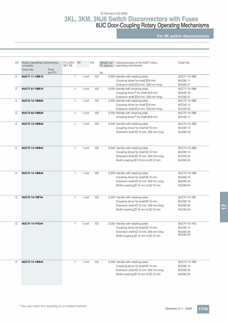
17
3KL, 3KM, 3NJ6 Switch Disconnectors with Fuses8UC Door-Coupling Rotary Operating Mechanisms
For 3K switch disconnectors
17/49Siemens LV 1 · 2009
p DT Rotary operating mechanisms, complete
PU (UNIT, SET, M)
PS* PG Weight per PU approx.
Individual parts of the 8UC7 rotary operating mechanism
Order No.
Order No. Price per PU kg
C 8UC71 11-1BB10 1 1 unit 103 0.200 Handle with masking plate
Coupling driver for shaft @ 6 mm
Extension shaft @ 6 mm, 300 mm long
8UC71 10-1BB
8UC60 11
8UC60 31
C 8UC71 61-1BB10 1 1 unit 103 0.200 Handle with masking plate
Coupling driver4) for shaft @ 6 mm
Extension shaft @ 6 mm, 300 mm long
8UC71 10-1BB
8UC60 16
8UC60 31
C 8UC72 12-1BB20 1 1 unit 103 0.200 Handle with masking plate
Coupling driver for shaft @ 8 mm
Extension shaft @ 8 mm, 300 mm long
8UC72 10-1BB
8UC60 12
8UC60 32
C 8UC72 62-1BB20 1 1 unit 103 0.200 Handle with masking plate
Coupling driver4) for shaft @ 8 mm
8UC72 10-1BB
8UC60 17
C 8UC73 13-1BB30 1 1 unit 103 0.200 Handle with masking plate 8UC73 10-1BB
Coupling driver for shaft @ 10 mm 8UC60 13
Extension shaft @ 10 mm, 300 mm long 8UC60 33
C 8UC73 14-1BB44 1 1 unit 103 0.200 Handle with masking plate 8UC73 10-1BB
Coupling driver for shaft @ 12 mm 8UC60 14
Extension shaft @ 12 mm, 300 mm long 8UC60 34
Shaft coupling @ 12 mm to @ 12 mm 8UC60 24
C 8UC74 14-1BB44 1 1 unit 103 0.200 Handle with masking plate 8UC74 10-1BB
Coupling driver for shaft @ 12 mm 8UC60 14
Extension shaft @ 12 mm, 300 mm long 8UC60 34
Shaft coupling @ 12 mm to @ 12 mm 8UC60 24
C 8UC74 14-1BF44 1 1 unit 103 0.200 Handle with masking plate 8UC74 10-1BF
Coupling driver for shaft @ 12 mm 8UC60 14
Extension shaft @ 12 mm, 300 mm long 8UC60 34
Shaft coupling @ 12 mm to @ 12 mm 8UC60 24
C 8UC74 14-1FG44 1 1 unit 103 0.200 Handle with masking plate 8UC74 10-1FG
Coupling driver for shaft @ 12 mm 8UC60 14
Extension shaft @ 12 mm, 300 mm long 8UC60 34
Shaft coupling @ 12 mm to @ 12 mm 8UC60 24
C 8UC74 14-1BB44 1 1 unit 103 0.200 Handle with masking plate 8UC74 10-1BB
Coupling driver for shaft @ 12 mm 8UC60 14
Extension shaft @ 12 mm, 300 mm long 8UC60 34
Shaft coupling @ 12 mm to @ 12 mm 8UC60 24
* You can order this quantity or a multiple thereof.
© Siemens AG 2009

3KL, 3KM, 3NJ6 Switch Disconnectors with Fuses 8UC Door-Coupling Rotary Operating Mechanisms
For 3K switch disconnectors
17/50 Siemens LV 1 · 2009
17
EMERGENCY-STOP door-coupling rotary operating mechanisms, complete (red handle, yellow masking plate with black inscription)Can be padlocked, with door interlocking
Supplied with seal and fixing screws
Switching device Rated current Cross-section of the actuating shaft
Torque Rotary operating mechanisms
Illustrated: Handle, masking plate
Type A mm Nm Size
Switch disconnectors with or without fuses
3KL501) 3KM501) 63 6 x 6 3 13KA501) 63 6 x 6 33KA511) 80 6 x 6 3
3KL52, 3KM52 125 8 x 8 7.5 2
3KL53, 3KM53 160 8 x 8 7.53KA52 125 8 x 8 7.53KA53 160 8 x 8 7.5
3KL55, 3KM55 250 10 x 10 16 3
3KL57, 3KM57 400 10 x 10 163KA55 250 10 x 10 163KA57 400 10 x 10 163KA58 630 10 x 10 16
3KE42 250 12 x 12 15 3
3KE43 400 12 x 12 153KE44 630 12 x 12 243KE45 1000 12 x 12 24
3KL612) 630 12 x 12 30 4
3KL622) 800 12 x 12
Switch disconnectors with operating linkage (for parallel connection)
3KE42 (2 units) 250 12 x 12 40 43KE43 (2 units) 400 12 x 12 403KE44 (2 units) 630 12 x 12 553KE45 (2 units) 1000 12 x 12 55
NSE00355
75
36
NSE00356
75
62
NSE00357
100
140
NSE00357
100
140NSE00358
100
200
NSE00358
100
200
1) Valid only for 3-pole switching devices. For 4-pole switching devices, an operating mechanism with 8 x 8 mm actuating shaft must be used, see lower level for 3KA52, 3KL52 or 3KM52.
2) Additionally required for 3KL61: 1 shaft coupling, Order No. 8UC92 53, see "Individual Parts".
© Siemens AG 2009

17
3KL, 3KM, 3NJ6 Switch Disconnectors with Fuses8UC Door-Coupling Rotary Operating Mechanisms
For 3K switch disconnectors
17/51Siemens LV 1 · 2009
DT Rotary operating mechanisms, complete
PU (UNIT, SET, M)
PS* PG Weight per PU approx.
Individual parts of the 8UC6 rotary operating mechanism
Order No.
Order No. Price per PU kg
C 8UC71 21-3BB10 1 1 unit 103 0.200 Handle with masking plate 8UC71 20-3BB
Coupling driver for shaft @ 6 mm 8UC60 11
Extension shaft @ 6 mm, 300 mm long 8UC60 31
C 8UC72 22-3BB20 1 1 unit 103 0.200 Handle with masking plate 8UC72 20-3BB
Coupling driver for shaft @ 8 mm 8UC60 12
Extension shaft @ 8 mm, 300 mm long 8UC60 32
C 8UC73 23-3BB30 1 1 unit 103 0.200 Handle with masking plate 8UC73 20-3BB
Coupling driver for shaft @ 10 mm 8UC60 13
Extension shaft @ 10 mm, 300 mm long 8UC60 33
C 8UC73 24-3BB44 1 1 unit 103 0.200 Handle with masking plate 8UC73 20-3BB
Coupling driver for shaft @ 12 mm 8UC60 14
Extension shaft @ 12 mm, 300 mm long 8UC60 34
Shaft coupling @ 12 mm to @ 12 mm 8UC60 24
C 8UC74 24-3BB44 1 1 unit 103 0.200 Handle with masking plate 8UC74 20-3BB
Coupling driver for shaft @ 12 mm 8UC60 14
Extension shaft @ 12 mm, 300 mm long 8UC60 34
Shaft coupling @ 12 mm to @ 12 mm 8UC60 24
* You can order this quantity or a multiple thereof.
© Siemens AG 2009

3KL, 3KM, 3NJ6 Switch Disconnectors with Fuses 8UC Door-Coupling Rotary Operating Mechanisms
Individual parts
17/52 Siemens LV 1 · 2009
17
n Selection and ordering data
1) Non-interchangeability features.2) Shortened coupling driver with reduced tolerance compensation.
For operating mechanism
Cross-section of the actuating shaft
A: Ti-grey han-dle, light-gray mask-ing plate
B: Red handle, yellow masking plate
DT Individual parts for 8UC7 door-coupling rotary operating mechanisms
PU (UNIT, SET, M)
PS* PG Weight per PU approx.
Order No. Price per PU
Type mm × mm kg
8UC71 10-1BB
Handles with masking plate (including flat gasket and fixing screws)
8UC71 6 × 6 A C 8UC71 10-1BB 1 1 unit 103 0.200B C 8UC71 20-3BB 1 1 unit 103 0.200
8UC72 10-6BD
8UC72 8 × 8 A C 8UC72 10-1BB 1 1 unit 103 0.200B C 8UC72 20-3BB 1 1 unit 103 0.200
8UC73 10-1BB
8UC73 10 × 10 A C 8UC73 10-1BB 1 1 unit 103 0.200B C 8UC73 20-3BB 1 1 unit 103 0.200
8UC74 10-1BB
8UC74 12 × 12 A C 8UC74 10-1BB 1 1 unit 103 0.200A C 8UC74 10-1BF 1 1 unit 103 0.200A C 8UC74 10-1FG 1 1 unit 103 0.200B C 8UC74 20-3BB 1 1 unit 103 0.200
For operating mechanism
Cross-section of the actuating shaft
DT Individual parts for 8UC6 door-coupling rotary operating mechanisms
PU (UNIT, SET, M)
PS* PG Weight per PU approx.
Order No. Price per PUType mm × mm kg
8UC60 11
Coupling drivers for 3K
8UC71 6 × 6 B 8UC60 11 1 1 unit 103 0.0788UC712) 6 × 6 A 8UC60 16 1 1 unit 103 0.070
8UC72 8 × 8 B 8UC60 12 1 1 unit 103 0.075
8UC722) 8 × 8 A 8UC60 17 1 1 unit 103 0.0438UC73 10 × 10 B 8UC60 13 1 1 unit 103 0.2518UC73/74 12 × 12 B 8UC60 14 1 1 unit 103 0.253
8UC60 31
Extension shafts 300 mm long
8UC71 6 × 6 B 8UC60 31 1 1 unit 103 0.0688UC72 8 × 8 B 8UC60 32 1 1 unit 103 0.132
8UC73 10 × 10 C 8UC60 33 1 1 unit 103 0.217
8UC73/74 12 × 12 B 8UC60 34 1 1 unit 103 0.315
8UC60 21 to 8UC6024
Extension shafts 600 mm long
8UC71 6 × 6 B 8UC60 81 1 1 unit 103 0.136
8UC72 8 × 8 B 8UC60 82 1 1 unit 103 0.2658UC73 10 × 10 B 8UC60 83 1 1 unit 103 0.4308UC73/74 12 × 12 B 8UC60 84 1 1 unit 103 0.640
8UC92 53
Shaft couplings
8UC71 6 × 6 B 8UC60 21 1 1 unit 103 0.0318UC72 8 × 8 B 8UC60 22 1 1 unit 103 0.0238UC73 10 × 10 B 8UC60 23 1 1 unit 103 0.0858UC73/74 12 × 12 B 8UC60 24 1 1 unit 103 0.0778UC74 (3KL61) 12 × 12 } 8UC92 53 1 1 unit 103 0.115
Reducers
8UC71 8 × 8 to 6 × 6 C 8UC70 58 1 1 unit 103 0.2008UC72 12 × 12 to 8 × 8 C 8UC70 50 1 1 unit 103 0.200
nse0_00372 Rivet
nse0_00373
Rivet
nse0_00374
RivetLug
NSE00375
* You can order this quantity or a multiple thereof.
© Siemens AG 2009
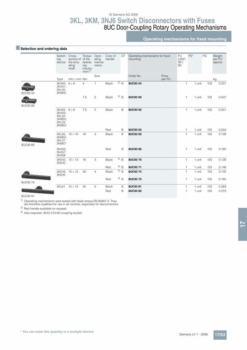
17
3KL, 3KM, 3NJ6 Switch Disconnectors with Fuses8UC Door-Coupling Rotary Operating Mechanisms
Operating mechanisms for fixed mounting
17/53Siemens LV 1 · 2009
n Selection and ordering data
1) Operating mechanisms were tested with triple torque EN 60947-3. They are therefore qualified for use in all controls, especially for disconnectors.
2) Red handle available on request.3) Also required: 3KX2 210-0H coupling socket.
Switch-ing device
Cross-section of the actu-ating shaft
Torque of the operat-ing mecha-nism1)
Oper-ating mecha-nisms
Color of handle
DT Operating mechanisms for fixed mounting
PU (UNIT, SET, M)
PS* PG Weight per PU approx.
Type mm × mm NmSize Order No. Price
per PU kg
8UC93 54
3KA50, 3KA51, 3KL50, 3KM50
6 × 6 4 1 Black 2) B 8UC93 54 1 1 unit 103 0.031
8UC93 60
7.5 2 Black 2) B 8UC93 60 1 1 unit 103 0.047
3KA52 3KA53, 3KL52, 3KM52, 3KL53, 3KM53
8 × 8 7.5 2 Black B 8UC93 62 1 1 unit 103 0.041
Red B 8UC93 63 1 1 unit 103 0.044
8UC93 65
3KL55, 3KM55, 3KL57, 3KM57
10 × 10 16 3 Black B 8UC93 65 1 1 unit 103 0.138
3KA55, 3KA57, 3KA58
Red B 8UC93 66 1 1 unit 103 0.160
3KE42, 3KE43
12 × 12 16 3 Black 3) B 8UC93 70 1 1 unit 103 0.128
Red 3) B 8UC93 71 1 1 unit 103 0.146
8UC93 74
3KE44, 3KE45
12 × 12 30 4 Black 3) B 8UC93 74 1 1 unit 103 0.145
Red 3) B 8UC93 75 1 1 unit 103 0.165
8UC93 81
3KL61 12 × 12 55 5 Black B 8UC93 81 1 1 unit 103 0.264
Red B 8UC93 82 1 1 unit 103 0.273
* You can order this quantity or a multiple thereof.
© Siemens AG 2009
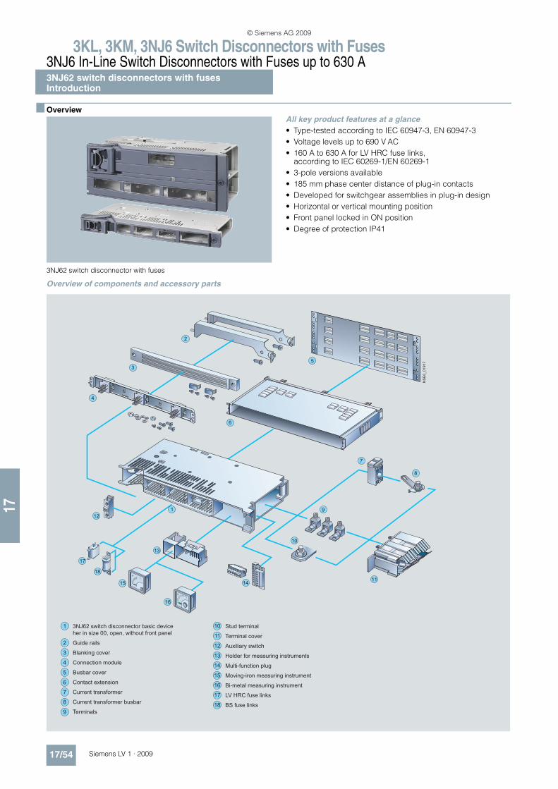
3KL, 3KM, 3NJ6 Switch Disconnectors with Fuses3NJ6 In-Line Switch Disconnectors with Fuses up to 630 A3NJ62 switch disconnectors with fusesIntroduction
17/54 Siemens LV 1 · 2009
17
n Overview
3NJ62 switch disconnector with fuses
All key product features at a glance
• Type-tested according to IEC 60947-3, EN 60947-3
• Voltage levels up to 690 V AC
• 160 A to 630 A for LV HRC fuse links, according to IEC 60269-1/EN 60269-1
• 3-pole versions available
• 185 mm phase center distance of plug-in contacts
• Developed for switchgear assemblies in plug-in design
• Horizontal or vertical mounting position
• Front panel locked in ON position
• Degree of protection IP41
Overview of components and accessory parts
3NJ62 switch disconnector basic device
her in size 00, open, without front panel
Guide rails
Blanking cover
Connection module
Busbar cover
Contact extension
Current transformer
Current transformer busbar
Terminals
1
2
3
4
5
6
7
8
9
Stud terminal
Terminal cover
Auxiliary switch
Holder for measuring instruments
Multi-function plug
Moving-iron measuring instrument
Bi-metal measuring instrument
LV HRC fuse links
BS fuse links
10
11
12
13
14
15
16
17
18
NSE0_01917
© Siemens AG 2009
3KL, 3KM, 3NJ6 Switch Disconnectors with Fuses3NJ6 In-Line Switch Disconnectors with Fuses up to 630 A
3NJ62 switch disconnectors with fusesIntroduction
17/55Siemens LV 1 · 2009
17
n Benefits
Key advantages for switchgear manufacturers due to the following:
• Compact, modular design
• Simple and efficient mounting due to incoming plug-in contact
• High packing density in the distribution board
• Cable connection with cable clamps or cable lugs
• Can be mounted in different switchgear cabinet depths
• Comprehensive range of accessories
The advantages for users are:
• Conversion, retrofitting and replacement without switching off the switchgear
• Dead-state fuse replacement
• Maintenance free
• High personal safety
• Operating handle can be locked in OFF position
• Clear and unambiguous switch position indicator
n Application
The plug-in 3NJ6 switch disconnectors with fuses are installed in low-voltage distribution boards where a minimum amount of space is available for a maximum number of cable ducts to the power distribution. They can be easily fitted in all common switchgear cabinets (minimum depth: 400 mm).
The plug-in 3NJ62 switch disconnectors with fuses are available for rated uninterrupted currents from 160 A to 630 A.
LV HRC fuse links according to IEC 60269-1/EN 60269-1 (sizes LV HRC 00 to LV HRC 3) provide overload and short-circuit pro-tection up to 690 V AC.
The switch disconnectors can be retrofitted at any time with aux-iliary switches, an ammeter (48 mm x 48 mm) and current trans-formers, with no extra space required. For installation in control cabinets of > 400 mm depth, the mounting depth of the switch disconnectors can be increased by 200 mm using a contact ex-tension. Further installation accessories, such as guide rails and blanking covers, complete the product range.
© Siemens AG 2009

3KL, 3KM, 3NJ6 Switch Disconnectors with Fuses3NJ6 In-Line Switch Disconnectors with Fuses up to 630 A3NJ62 switch disconnectors with fusesfor LV HRC fuse links
17/56 Siemens LV 1 · 2009* You can order this quantity or a multiple thereof.
17
n Selection and ordering data
Rated current In Size DT Order No. Price per PU
PU(UNIT, M)
PS* PG Weight per PU approx.
A kg
3-pole, standard switching capacity S
Manually operated 160 00/000 } 3NJ62 03-1AA0@-@@@@ 1 1 unit 143 3.630
250 1 } 3NJ62 13-1AA0@-@@@@ 1 1 unit 143 6.750
400 2/1 } 3NJ62 23-1AA0@-@@@@ 1 1 unit 143 15.000
630 3/2 } 3NJ62 33-1AA0@-@@@@ 15.360
3-pole, high switching capacity H
Manually operated 160 00/000 } 3NJ62 03-3AA0@-@@@@ 1 1 unit 143 3.630
250 1 } 3NJ62 13-3AA0@-@@@@ 1 1 unit 143 7.750
400 2/1 } 3NJ62 23-3AA0@-@@@@ 1 1 unit 143 15.000
630 3/2 } 3NJ62 33-3AA0@-@@@@ 1 1 unit 143 15.360
Order No. supplement Add. price
Standard Order No. supplement (more Order No. supplements on page 17/57 onwards)
Without auxiliary switches, ammeters, current transformers } Without0 0 A A 0
© Siemens AG 2009
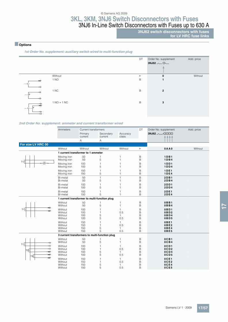
3KL, 3KM, 3NJ6 Switch Disconnectors with Fuses3NJ6 In-Line Switch Disconnectors with Fuses up to 630 A
3NJ62 switch disconnectors with fusesfor LV HRC fuse links
17/57Siemens LV 1 · 2009
17
n Options
2nd Order No. supplement: ammeter and current transformer wired
1st Order No. supplement: auxiliary switch wired to multi-function plug
DT Order No. supplement
3NJ62 ..-.... @-....
Add. price
Without } 0 Without
1 NO B 1
1 NC B 2
1 NO + 1 NC B 3
Ammeters Current transformers DT Order No. supplement
3NJ62 ..-.....-@@@@
Add. price
Primarycurrent
Secondary current
Accuracy class
A A
For size LV HRC 00
Without Without Without Without } 0 A A 0 Without
1 current transformer to 1 ammeter
Moving iron 50 1 1 B 1 D B 1Moving iron 50 5 1 B 1 D B 4
Moving iron 100 1 1 B 1 D D 1Moving iron 100 5 1 B 1 D D 4
Moving iron 150 1 1 B 1 D E 1Moving iron 150 5 1 B 1 D E 4
Bi-metal 50 1 1 B 2 D B 1Bi-metal 50 5 1 B 2 D B 4
Bi-metal 100 1 1 B 2 D D 1Bi-metal 100 5 1 B 2 D D 4
Bi-metal 150 1 1 B 2 D E 1Bi-metal 150 5 1 B 2 D E 4
1 current transformer to multi-function plug
Without 50 1 1 B 0 B B 1Without 50 5 1 B 0 B B 4
Without 100 1 1 B 0 B D 1Without 100 1 0.5 B 0 B D 2Without 100 5 1 B 0 B D 4Without 100 5 0.5 B 0 B D 5
Without 150 1 1 B 0 B E 1Without 150 1 0.5 B 0 B E 2Without 150 5 1 B 0 B E 4Without 150 5 0.5 B 0 B E 5
3 current transformers to multi-function plug
Without 50 1 1 B 0 C B 1Without 50 5 1 B 0 C B 4
Without 100 1 1 B 0 C D 1Without 100 1 0.5 B 0 C D 2Without 100 5 1 B 0 C D 4Without 100 5 0.5 B 0 C D 5
Without 150 1 1 B 0 C E 1Without 150 1 0.5 B 0 C E 2Without 150 5 1 B 0 C E 4Without 150 5 0.5 B 0 C E 5
T1A
T1
T1
T2
T3
© Siemens AG 2009
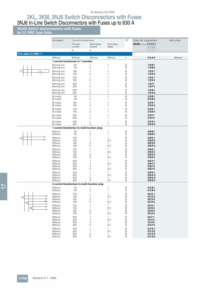
3KL, 3KM, 3NJ6 Switch Disconnectors with Fuses3NJ6 In-Line Switch Disconnectors with Fuses up to 630 A3NJ62 switch disconnectors with fusesfor LV HRC fuse links
17/58 Siemens LV 1 · 2009
17
For size LV HRC 1
Without Without Without Without } 0 A A 0 Without
1 current transformer to 1 ammeter
Moving iron 50 1 1 B 1 D B 1Moving iron 50 5 1 B 1 D B 4
Moving iron 100 1 1 B 1 D D 1Moving iron 100 5 1 B 1 D D 4
Moving iron 150 1 1 B 1 D E 1Moving iron 150 5 1 B 1 D E 4
Moving iron 200 1 1 B 1 D F1Moving iron 200 5 1 B 1 D F 4
Moving iron 250 1 1 B 1 D G1Moving iron 250 5 1 B 1 D G 4
Bi-metal 50 1 1 B 2 D B 1Bi-metal 50 5 1 B 2 D B 4
Bi-metal 100 1 1 B 2 D D 1Bi-metal 100 5 1 B 2 D D 4
Bi-metal 150 1 1 B 2 D E 1Bi-metal 150 5 1 B 2 D E 4
Bi-metal 200 1 1 B 2 D F1Bi-metal 200 5 1 B 2 D F4
Bi-metal 250 1 1 B 2 D G 1Bi-metal 250 5 1 B 2 D G 4
1 current transformer to multi-function plug
Without 50 1 1 B 0 B B 1Without 50 5 1 B 0 B B 4
Without 100 1 1 B 0 B D 1Without 100 1 0.5 B 0 B D 2Without 100 5 1 B 0 B D 4Without 100 5 0.5 B 0 B D 5
Without 150 1 1 B 0 B E 1Without 150 1 0.5 B 0 B E 2Without 150 5 1 B 0 B E 4Without 150 5 0.5 B 0 B E 5
Without 200 1 1 B 0 B F 1Without 200 1 0.5 B 0 B F 2Without 200 5 1 B 0 B F 4Without 200 5 0.5 B 0 B F 5
Without 250 1 1 B 0 B G 1Without 250 1 0.5 B 0 B G 2Without 250 5 1 B 0 B G 4Without 250 5 0.5 B 0 B G 5
3 current transformers to multi-function plug
Without 50 1 1 B 0 C B 1Without 50 5 1 B 0 C B 4
Without 100 1 1 B 0C D 1Without 100 1 0.5 B 0C D 2Without 100 5 1 B 0C D 4Without 100 5 0.5 B 0C D 5
Without 150 1 1 B 0C E 1Without 150 1 0.5 B 0C E 2Without 150 5 1 B 0C E 4Without 150 5 0.5 B 0C E 5
Without 200 1 1 B 0C F 1Without 200 1 0.5 B 0C F 2Without 200 5 1 B 0 C F4Without 200 5 0.5 B 0 C F 5
Without 250 1 1 B 0 C G 1Without 250 1 0.5 B 0 C G 2Without 250 5 1 B 0 C G 4Without 250 5 0.5 B 0 C G 5
Ammeters Current transformers DT Order No. supplement
3NJ62 ..-.....-@@@@
Add. price
Primarycurrent
Secondary current
Accuracy class
A A
T1A
T1
T1
T2
T3
© Siemens AG 2009
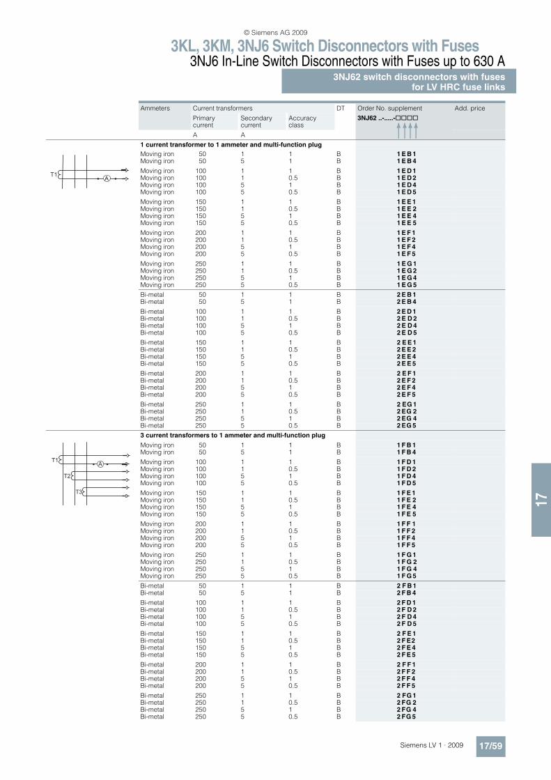
3KL, 3KM, 3NJ6 Switch Disconnectors with Fuses3NJ6 In-Line Switch Disconnectors with Fuses up to 630 A
3NJ62 switch disconnectors with fusesfor LV HRC fuse links
17/59Siemens LV 1 · 2009
17
1 current transformer to 1 ammeter and multi-function plug
Moving iron 50 1 1 B 1 E B 1Moving iron 50 5 1 B 1 E B 4
Moving iron 100 1 1 B 1 E D 1Moving iron 100 1 0.5 B 1 E D 2Moving iron 100 5 1 B 1 E D 4Moving iron 100 5 0.5 B 1 E D 5
Moving iron 150 1 1 B 1 E E 1Moving iron 150 1 0.5 B 1 E E 2Moving iron 150 5 1 B 1 E E 4Moving iron 150 5 0.5 B 1 E E 5
Moving iron 200 1 1 B 1 E F 1Moving iron 200 1 0.5 B 1 E F 2Moving iron 200 5 1 B 1 E F 4Moving iron 200 5 0.5 B 1 E F 5
Moving iron 250 1 1 B 1 E G 1Moving iron 250 1 0.5 B 1 E G 2Moving iron 250 5 1 B 1 E G 4Moving iron 250 5 0.5 B 1 E G 5
Bi-metal 50 1 1 B 2 E B 1Bi-metal 50 5 1 B 2 E B 4
Bi-metal 100 1 1 B 2 E D 1Bi-metal 100 1 0.5 B 2 E D 2Bi-metal 100 5 1 B 2 E D 4Bi-metal 100 5 0.5 B 2 E D 5
Bi-metal 150 1 1 B 2 E E 1Bi-metal 150 1 0.5 B 2 E E 2Bi-metal 150 5 1 B 2 E E 4Bi-metal 150 5 0.5 B 2 E E 5
Bi-metal 200 1 1 B 2 E F 1Bi-metal 200 1 0.5 B 2 E F 2Bi-metal 200 5 1 B 2 E F 4Bi-metal 200 5 0.5 B 2 E F 5
Bi-metal 250 1 1 B 2 EG 1Bi-metal 250 1 0.5 B 2 EG 2Bi-metal 250 5 1 B 2 EG 4Bi-metal 250 5 0.5 B 2 EG 5
3 current transformers to 1 ammeter and multi-function plug
Moving iron 50 1 1 B 1 F B 1Moving iron 50 5 1 B 1 F B 4
Moving iron 100 1 1 B 1 F D 1Moving iron 100 1 0.5 B 1 F D 2Moving iron 100 5 1 B 1 F D 4Moving iron 100 5 0.5 B 1 F D 5
Moving iron 150 1 1 B 1 F E 1Moving iron 150 1 0.5 B 1 F E 2Moving iron 150 5 1 B 1 F E 4Moving iron 150 5 0.5 B 1 F E 5
Moving iron 200 1 1 B 1 F F 1Moving iron 200 1 0.5 B 1 F F 2Moving iron 200 5 1 B 1 F F 4Moving iron 200 5 0.5 B 1 F F 5
Moving iron 250 1 1 B 1 F G 1Moving iron 250 1 0.5 B 1 F G 2Moving iron 250 5 1 B 1 F G 4Moving iron 250 5 0.5 B 1 F G 5
Bi-metal 50 1 1 B 2 F B 1Bi-metal 50 5 1 B 2 F B 4
Bi-metal 100 1 1 B 2 F D 1Bi-metal 100 1 0.5 B 2 F D 2Bi-metal 100 5 1 B 2 F D 4Bi-metal 100 5 0.5 B 2 F D 5
Bi-metal 150 1 1 B 2 F E 1Bi-metal 150 1 0.5 B 2 F E2Bi-metal 150 5 1 B 2 F E 4Bi-metal 150 5 0.5 B 2 F E 5
Bi-metal 200 1 1 B 2 F F 1Bi-metal 200 1 0.5 B 2 F F 2Bi-metal 200 5 1 B 2 F F 4Bi-metal 200 5 0.5 B 2 F F 5
Bi-metal 250 1 1 B 2 FG 1Bi-metal 250 1 0.5 B 2 FG 2Bi-metal 250 5 1 B 2 FG 4Bi-metal 250 5 0.5 B 2 FG 5
Ammeters Current transformers DT Order No. supplement
3NJ62 ..-.....-@@@@
Add. price
Primarycurrent
Secondary current
Accuracy class
A A
AT1
T1
T2
T3
A
© Siemens AG 2009

3KL, 3KM, 3NJ6 Switch Disconnectors with Fuses3NJ6 In-Line Switch Disconnectors with Fuses up to 630 A3NJ62 switch disconnectors with fusesfor LV HRC fuse links
17/60 Siemens LV 1 · 2009
17
For size LV HRC 2
Without Without Without Without } 0 A A 0 Without
1 current transformer to 1 ammeter
Moving iron 300 1 1 B 1 D H 1Moving iron 300 5 1 B 1 D H 4
Moving iron 400 1 1 B 1 D J 1Moving iron 400 5 1 B 1 D J 4
Bi-metal 300 1 1 B 2 D H 1Bi-metal 300 5 1 B 2 D H 4
Bi-metal 400 1 1 B 2 D J 1Bi-metal 400 5 1 B 2 D J 4
1 current transformer to multi-function plug
Without 300 1 1 B 0 B H 1Without 300 1 0.5 B 0 B H 2Without 300 5 1 B 0 B H 4Without 300 5 0.5 B 0 B H 5
Without 400 1 1 B 0 B J 1Without 400 1 0.5 B 0 B J 2Without 400 5 1 B 0 B J 4Without 400 5 0.5 B 0 B J 5
3 current transformers to multi-function plug
Without 300 1 1 B 0 C H 1Without 300 1 0.5 B 0 C H 2Without 300 5 1 B 0 C H 4Without 300 5 0.5 B 0 C H 5
Without 400 1 1 B 0 C J 1Without 400 1 0.5 B 0 C J 2Without 400 5 1 B 0 C J 4Without 400 5 0.5 B 0 C J 5
1 current transformer to 1 ammeter and multi-function plug
Moving iron 300 1 1 B 1 E H 1Moving iron 300 1 0.5 B 1 E H 2Moving iron 300 5 1 B 1 E H 4Moving iron 300 5 0.5 B 1 E H 5
Moving iron 400 1 1 B 1 E J 1Moving iron 400 1 0.5 B 1 E J 2Moving iron 400 5 1 B 1 E J 4Moving iron 400 5 0.5 B 1 E J 5
Bi-metal 300 1 1 B 2 E H 1Bi-metal 300 1 0.5 B 2 E H 2Bi-metal 300 5 1 B 2 E H 4Bi-metal 300 5 0.5 B 2 E H 5
Bi-metal 400 1 1 B 2 E J 1Bi-metal 400 1 0.5 B 2 E J 2Bi-metal 400 5 1 B 2 E J 4Bi-metal 400 5 0.5 B 2 E J 5
3 current transformers to 1 ammeter and multi-function plug
Moving iron 300 1 1 B 1 F H 1Moving iron 300 1 0.5 B 1 F H 2Moving iron 300 5 1 B 1 F H 4Moving iron 300 5 0.5 B 1 F H 5
Moving iron 400 1 1 B 1 F J 1Moving iron 400 1 0.5 B 1 F J 2Moving iron 400 5 1 B 1 F J 4Moving iron 400 5 0.5 B 1 F J 5
Bi-metal 300 1 1 B 2 F H 1Bi-metal 300 1 0.5 B 2 F H 2Bi-metal 300 5 1 B 2 F H 4Bi-metal 300 5 0.5 B 2 F H 5
Bi-metal 400 1 1 B 2 F J 1Bi-metal 400 1 0.5 B 2 F J 2Bi-metal 400 5 1 B 2 F J 4Bi-metal 400 5 0.5 B 2 F J 5
Ammeters Current transformers DT Order No. supplement
3NJ62 ..-.....-@@@@
Add. price
Primarycurrent
Secondary current
Accuracy class
A A
T1A
T1
T1
T2
T3
AT1
T1
T2
T3
A
© Siemens AG 2009
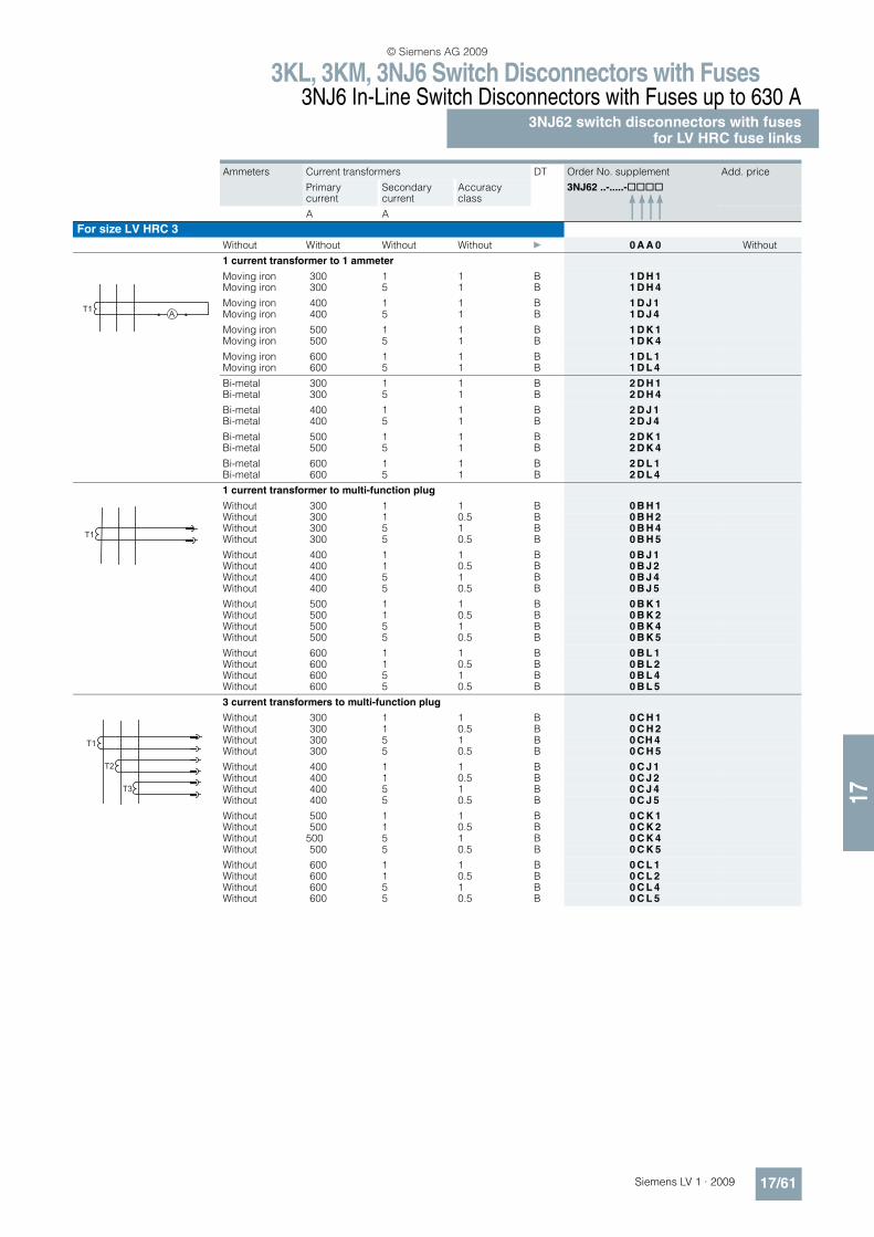
3KL, 3KM, 3NJ6 Switch Disconnectors with Fuses3NJ6 In-Line Switch Disconnectors with Fuses up to 630 A
3NJ62 switch disconnectors with fusesfor LV HRC fuse links
17/61Siemens LV 1 · 2009
17
For size LV HRC 3
Without Without Without Without } 0 A A 0 Without
1 current transformer to 1 ammeter
Moving iron 300 1 1 B 1 D H 1Moving iron 300 5 1 B 1 D H 4
Moving iron 400 1 1 B 1 D J 1Moving iron 400 5 1 B 1 D J 4
Moving iron 500 1 1 B 1 D K 1Moving iron 500 5 1 B 1 D K 4
Moving iron 600 1 1 B 1 D L 1Moving iron 600 5 1 B 1 D L 4
Bi-metal 300 1 1 B 2 D H 1Bi-metal 300 5 1 B 2 D H 4
Bi-metal 400 1 1 B 2 D J 1Bi-metal 400 5 1 B 2 D J 4
Bi-metal 500 1 1 B 2 D K 1Bi-metal 500 5 1 B 2 D K 4
Bi-metal 600 1 1 B 2 D L 1Bi-metal 600 5 1 B 2 D L 4
1 current transformer to multi-function plug
Without 300 1 1 B 0 B H 1Without 300 1 0.5 B 0 B H 2Without 300 5 1 B 0 B H 4Without 300 5 0.5 B 0 B H 5
Without 400 1 1 B 0 B J 1Without 400 1 0.5 B 0 B J 2Without 400 5 1 B 0 B J 4Without 400 5 0.5 B 0 B J 5
Without 500 1 1 B 0 B K 1Without 500 1 0.5 B 0 B K 2Without 500 5 1 B 0 B K 4Without 500 5 0.5 B 0 B K 5
Without 600 1 1 B 0 B L 1Without 600 1 0.5 B 0 B L 2Without 600 5 1 B 0 B L 4Without 600 5 0.5 B 0 B L 5
3 current transformers to multi-function plug
Without 300 1 1 B 0 C H 1Without 300 1 0.5 B 0 C H 2Without 300 5 1 B 0 CH 4Without 300 5 0.5 B 0 C H 5
Without 400 1 1 B 0 C J 1Without 400 1 0.5 B 0 C J 2Without 400 5 1 B 0 C J 4Without 400 5 0.5 B 0 C J 5
Without 500 1 1 B 0 C K 1Without 500 1 0.5 B 0 C K 2Without 500 5 1 B 0 C K 4Without 500 5 0.5 B 0 C K 5
Without 600 1 1 B 0 C L 1Without 600 1 0.5 B 0 C L 2Without 600 5 1 B 0 C L 4Without 600 5 0.5 B 0 C L 5
Ammeters Current transformers DT Order No. supplement
3NJ62 ..-.....-@@@@
Add. price
Primarycurrent
Secondary current
Accuracy class
A A
T1A
T1
T1
T2
T3
© Siemens AG 2009
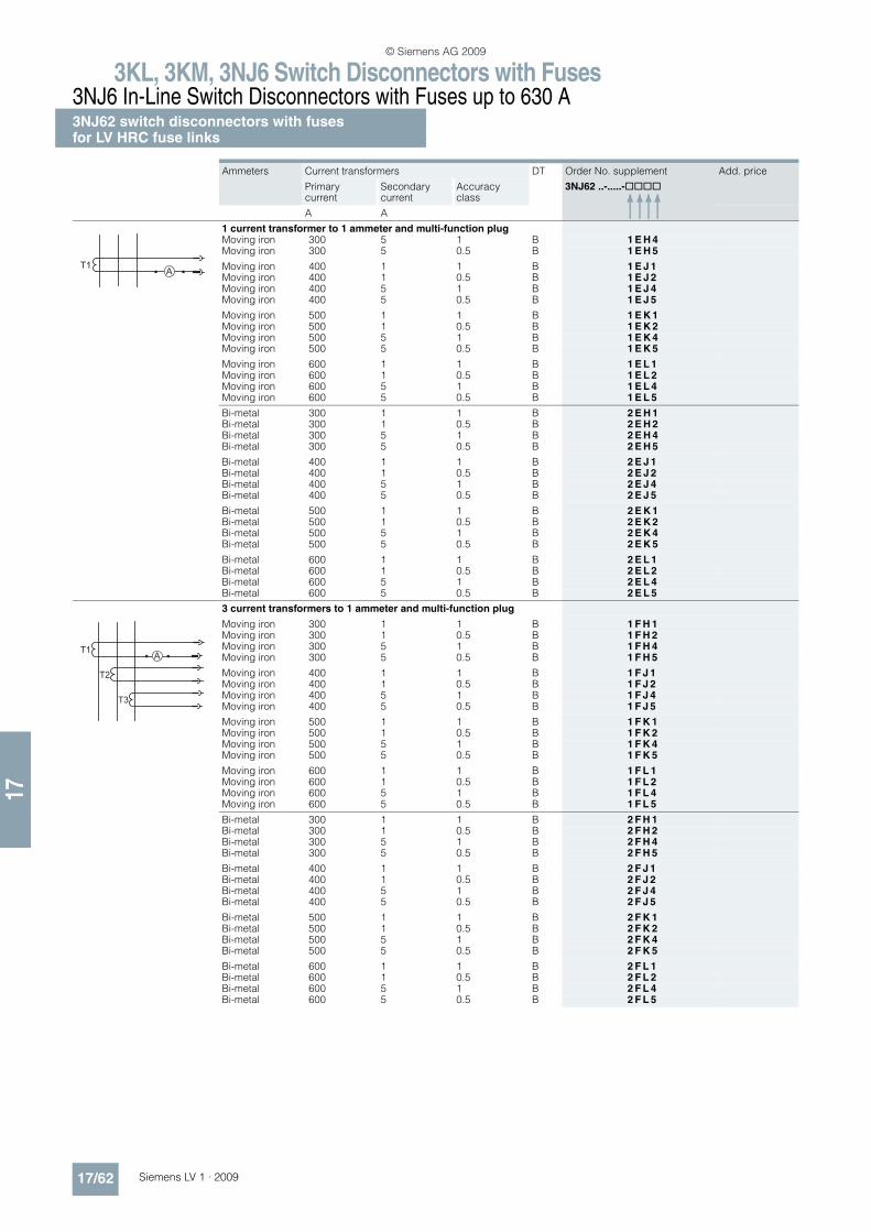
3KL, 3KM, 3NJ6 Switch Disconnectors with Fuses3NJ6 In-Line Switch Disconnectors with Fuses up to 630 A3NJ62 switch disconnectors with fusesfor LV HRC fuse links
17/62 Siemens LV 1 · 2009
17
1 current transformer to 1 ammeter and multi-function plugMoving iron 300 5 1 B 1 E H 4Moving iron 300 5 0.5 B 1 E H 5
Moving iron 400 1 1 B 1 E J 1Moving iron 400 1 0.5 B 1 E J 2Moving iron 400 5 1 B 1 E J 4Moving iron 400 5 0.5 B 1 E J 5
Moving iron 500 1 1 B 1 E K 1Moving iron 500 1 0.5 B 1 E K 2Moving iron 500 5 1 B 1 E K 4Moving iron 500 5 0.5 B 1 E K 5
Moving iron 600 1 1 B 1 E L 1Moving iron 600 1 0.5 B 1 E L 2Moving iron 600 5 1 B 1 E L 4Moving iron 600 5 0.5 B 1 E L 5
Bi-metal 300 1 1 B 2 E H 1Bi-metal 300 1 0.5 B 2 E H 2Bi-metal 300 5 1 B 2 E H 4Bi-metal 300 5 0.5 B 2 E H 5
Bi-metal 400 1 1 B 2 E J 1Bi-metal 400 1 0.5 B 2 E J 2Bi-metal 400 5 1 B 2 E J 4Bi-metal 400 5 0.5 B 2 E J 5
Bi-metal 500 1 1 B 2 E K 1Bi-metal 500 1 0.5 B 2 E K 2Bi-metal 500 5 1 B 2 E K 4Bi-metal 500 5 0.5 B 2 E K 5
Bi-metal 600 1 1 B 2 E L 1Bi-metal 600 1 0.5 B 2 E L 2Bi-metal 600 5 1 B 2 E L 4Bi-metal 600 5 0.5 B 2 E L 5
3 current transformers to 1 ammeter and multi-function plug
Moving iron 300 1 1 B 1 F H 1Moving iron 300 1 0.5 B 1 F H 2Moving iron 300 5 1 B 1 F H 4Moving iron 300 5 0.5 B 1 F H 5
Moving iron 400 1 1 B 1 F J 1Moving iron 400 1 0.5 B 1 F J 2Moving iron 400 5 1 B 1 F J 4Moving iron 400 5 0.5 B 1 F J 5
Moving iron 500 1 1 B 1 F K 1Moving iron 500 1 0.5 B 1 F K 2Moving iron 500 5 1 B 1 F K 4Moving iron 500 5 0.5 B 1 F K 5
Moving iron 600 1 1 B 1 F L 1Moving iron 600 1 0.5 B 1 F L 2Moving iron 600 5 1 B 1 F L 4Moving iron 600 5 0.5 B 1 F L 5
Bi-metal 300 1 1 B 2 F H 1Bi-metal 300 1 0.5 B 2 F H 2Bi-metal 300 5 1 B 2 F H 4Bi-metal 300 5 0.5 B 2 F H 5
Bi-metal 400 1 1 B 2 F J 1Bi-metal 400 1 0.5 B 2 F J 2Bi-metal 400 5 1 B 2 F J 4Bi-metal 400 5 0.5 B 2 F J 5
Bi-metal 500 1 1 B 2 F K 1Bi-metal 500 1 0.5 B 2 F K 2Bi-metal 500 5 1 B 2 F K 4Bi-metal 500 5 0.5 B 2 F K 5
Bi-metal 600 1 1 B 2 F L 1Bi-metal 600 1 0.5 B 2 F L 2Bi-metal 600 5 1 B 2 F L 4Bi-metal 600 5 0.5 B 2 F L 5
Ammeters Current transformers DT Order No. supplement
3NJ62 ..-.....-@@@@
Add. price
Primarycurrent
Secondary current
Accuracy class
A A
AT1
T1
T2
T3
A
© Siemens AG 2009

3KL, 3KM, 3NJ6 Switch Disconnectors with Fuses3NJ6 In-Line Switch Disconnectors with Fuses up to 630 A
3NJ62 switch disconnectors with fusesfor LV HRC fuse links
17/63Siemens LV 1 · 2009* You can order this quantity or a multiple thereof.
17
n Accessories
Version DT Order No. Price per PU
PU(UNIT, M)
PS* PG Weight per PU approx.
kg
Size LV HRC 00
3NJ69 23-1BA00
Terminals
Single terminal for 2-/3-pole devices, 2.5 ... 95 mm2 A 3NJ69 23-1BA00 1 3 units 143 0.210
3NJ69 23-1DA00
Terminal covers
For 2-/3-pole devices A 3NJ69 23-1DA00 1 1 unit 143 0.063
3NJ69 23-1EB00
Contact extensions
3-pole A 3NJ69 23-1EB00 1 1 unit 143 1.700
3NJ69 20-2BB00
3NJ69 00-2BC00
Auxiliary switches
1 NO contact with cover A 3NJ69 20-2BB00 1 1 unit 143 0.080
1 NO contact A 3NJ69 00-2BC00 1 1 unit 143 0.020
1 NC contact with cover A 3NJ69 20-2CB00 1 1 unit 143 0.080
1 NC contact A 3NJ69 00-2CC00 1 1 unit 143 0.020
3NJ69 20-3BD11
Current transformers For main devices and contact extensions
= Feed-through opening diameter
50 A/1 A Class 1 1 VA, 21 mm A 3NJ69 20-3BB11 1 1 unit 143 0.16050 A/5 A Class 1 1 VA, 21 mm A 3NJ69 20-3BB21 1 1 unit 143 0.160
100 A/1 A Class 1 2.5 VA, 21 mm A 3NJ69 20-3BD11 1 1 unit 143 0.160100 A/1 A Class 0.5 2.5 VA, 21 mm A 3NJ69 20-3BD12 1 1 unit 143 0.160100 A/1 A Class 0.5 calibrated 1.5 VA, 14 mm D 3NJ69 20-3BD13 1 1 unit 143 0.160
100 A/5 A Class 1 2.5 VA, 21 mm A 3NJ69 20-3BD21 1 1 unit 143 0.160100 A/5 A Class 0.5 2.5 VA, 21 mm A 3NJ69 20-3BD22 1 1 unit 143 0.160100 A/5 A Class 0.5 calibrated 1.5 VA, 14mm D 3NJ69 20-3BD23 1 1 unit 143 0.160
150 A/1 A Class 1 2.5 VA, 21 mm A 3NJ69 20-3BE11 1 1 unit 143 0.170150 A/1 A Class 0.5 2.5 VA, 21 mm A 3NJ69 20-3BE12 1 1 unit 143 0.170150 A/1 A Class 0.5 calibrated 2.5 VA, 14 mm D 3NJ69 20-3BE13 1 1 unit 143 0.170
150 A/5 A Class 1 2.5 VA, 21 mm A 3NJ69 20-3BE21 1 1 unit 143 0.170150 A/5 A Class 0.5 2.5 VA, 21 mm A 3NJ69 20-3BE22 1 1 unit 143 0.170150 A/5 A Class 0.5 calibrated 2.5 VA, 14 mm D 3NJ69 20-3BE23 1 1 unit 143 0.170
3NJ69 20-3DB00
3NJ69 20-3DC00
3NJ69 20-3DD00
Current transformer busbars for current transformers with feed-through opening 21 mm
For 1 current transformer A 3NJ69 20-3DB00 1 1 unit 143 0.070
For 3 current transformers A 3NJ69 20-3DC00 1 1 unit 143 0.210
For 4 current transformers1) A 3NJ69 20-3DD00 1 1 unit 143 0.280
Current transformer busbars for current transformers with feed-through opening 14 mm
For 1 current transformer A 3NJ69 20-3DE00 1 1 unit 143 0.070
For 3 current transformers A 3NJ69 20-3DF00 1 1 unit 143 0.210
For 4 current transformers1) A 3NJ69 20-3DG00 1 1 unit 143 0.280
1) Not available in combinations with multi-function plug.
© Siemens AG 2009
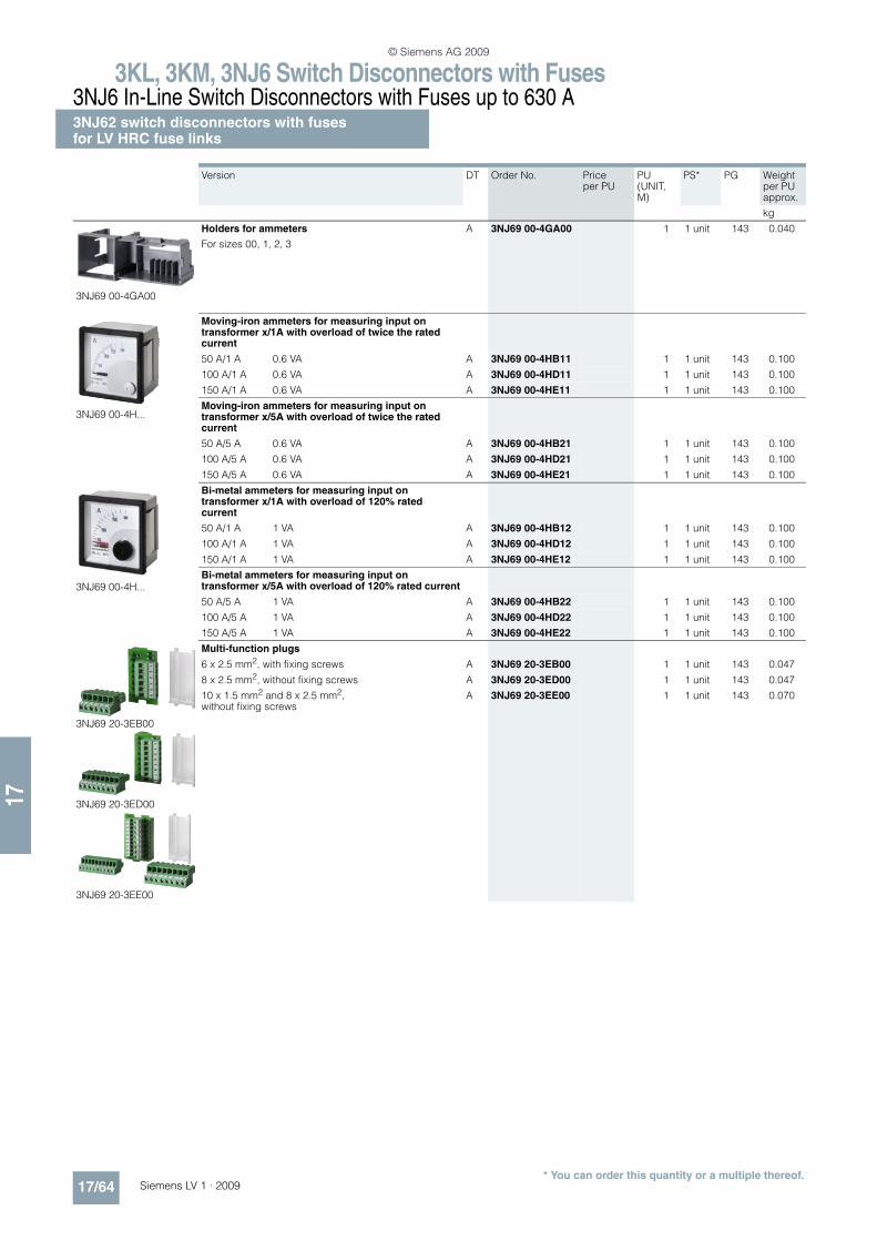
3KL, 3KM, 3NJ6 Switch Disconnectors with Fuses3NJ6 In-Line Switch Disconnectors with Fuses up to 630 A3NJ62 switch disconnectors with fusesfor LV HRC fuse links
17/64 Siemens LV 1 · 2009* You can order this quantity or a multiple thereof.
17
Version DT Order No. Price per PU
PU(UNIT, M)
PS* PG Weight per PU approx.
kg
3NJ69 00-4GA00
Holders for ammeters
For sizes 00, 1, 2, 3
A 3NJ69 00-4GA00 1 1 unit 143 0.040
3NJ69 00-4H...
Moving-iron ammeters for measuring input on transformer x/1A with overload of twice the rated current
50 A/1 A 0.6 VA A 3NJ69 00-4HB11 1 1 unit 143 0.100
100 A/1 A 0.6 VA A 3NJ69 00-4HD11 1 1 unit 143 0.100
150 A/1 A 0.6 VA A 3NJ69 00-4HE11 1 1 unit 143 0.100
Moving-iron ammeters for measuring input on transformer x/5A with overload of twice the rated current
50 A/5 A 0.6 VA A 3NJ69 00-4HB21 1 1 unit 143 0.100
100 A/5 A 0.6 VA A 3NJ69 00-4HD21 1 1 unit 143 0.100
150 A/5 A 0.6 VA A 3NJ69 00-4HE21 1 1 unit 143 0.100
3NJ69 00-4H...
Bi-metal ammeters for measuring input on transformer x/1A with overload of 120% rated current
50 A/1 A 1 VA A 3NJ69 00-4HB12 1 1 unit 143 0.100
100 A/1 A 1 VA A 3NJ69 00-4HD12 1 1 unit 143 0.100
150 A/1 A 1 VA A 3NJ69 00-4HE12 1 1 unit 143 0.100
Bi-metal ammeters for measuring input on transformer x/5A with overload of 120% rated current
50 A/5 A 1 VA A 3NJ69 00-4HB22 1 1 unit 143 0.100
100 A/5 A 1 VA A 3NJ69 00-4HD22 1 1 unit 143 0.100
150 A/5 A 1 VA A 3NJ69 00-4HE22 1 1 unit 143 0.100
3NJ69 20-3EB00
3NJ69 20-3ED00
3NJ69 20-3EE00
Multi-function plugs
6 x 2.5 mm2, with fixing screws A 3NJ69 20-3EB00 1 1 unit 143 0.047
8 x 2.5 mm2, without fixing screws A 3NJ69 20-3ED00 1 1 unit 143 0.047
10 x 1.5 mm2 and 8 x 2.5 mm2, without fixing screws
A 3NJ69 20-3EE00 1 1 unit 143 0.070
© Siemens AG 2009
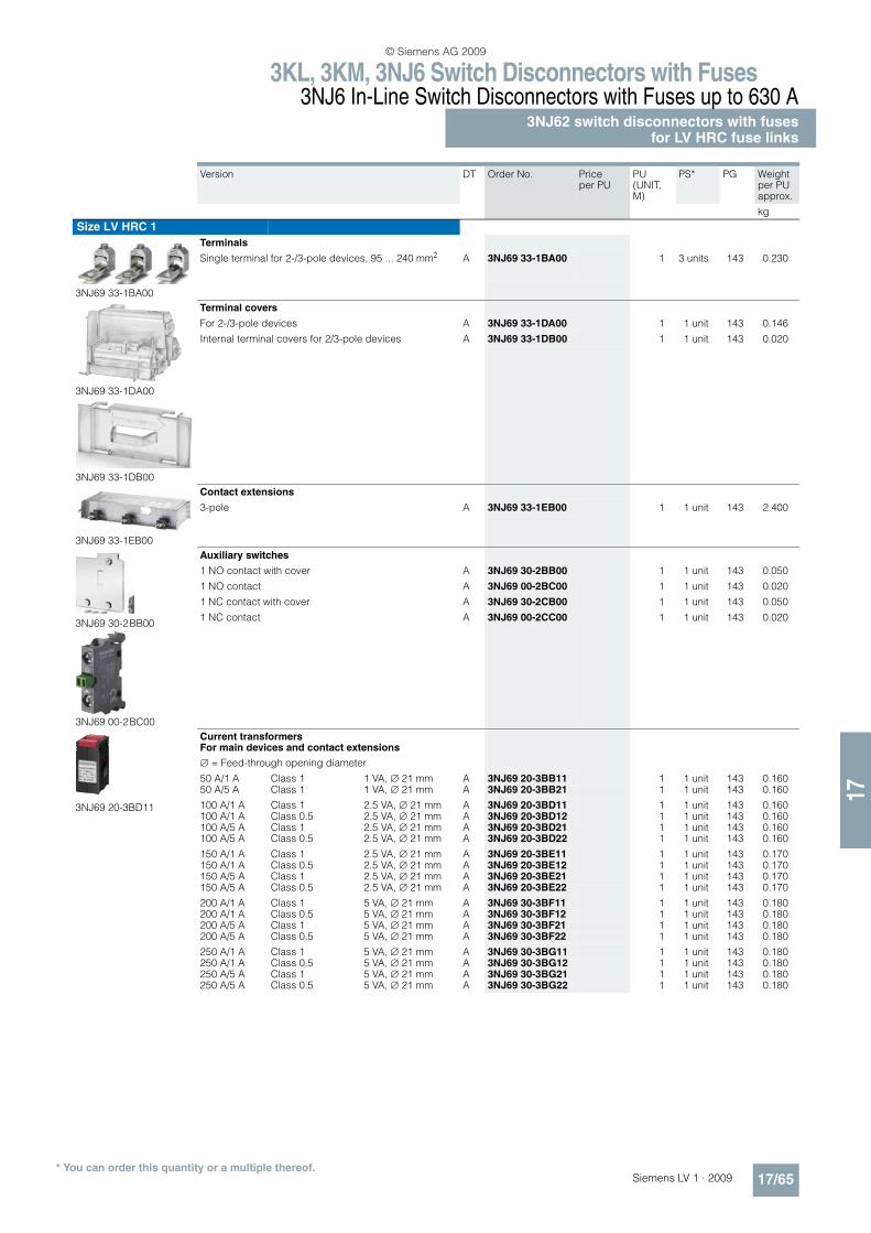
3KL, 3KM, 3NJ6 Switch Disconnectors with Fuses3NJ6 In-Line Switch Disconnectors with Fuses up to 630 A
3NJ62 switch disconnectors with fusesfor LV HRC fuse links
17/65Siemens LV 1 · 2009* You can order this quantity or a multiple thereof.
17
Version DT Order No. Price per PU
PU(UNIT, M)
PS* PG Weight per PU approx.
kg
Size LV HRC 1
3NJ69 33-1BA00
Terminals
Single terminal for 2-/3-pole devices, 95 ... 240 mm2 A 3NJ69 33-1BA00 1 3 units 143 0.230
3NJ69 33-1DA00
3NJ69 33-1DB00
Terminal covers
For 2-/3-pole devices A 3NJ69 33-1DA00 1 1 unit 143 0.146
Internal terminal covers for 2/3-pole devices A 3NJ69 33-1DB00 1 1 unit 143 0.020
3NJ69 33-1EB00
Contact extensions
3-pole A 3NJ69 33-1EB00 1 1 unit 143 2.400
3NJ69 30-2BB00
3NJ69 00-2BC00
Auxiliary switches
1 NO contact with cover A 3NJ69 30-2BB00 1 1 unit 143 0.050
1 NO contact A 3NJ69 00-2BC00 1 1 unit 143 0.020
1 NC contact with cover A 3NJ69 30-2CB00 1 1 unit 143 0.050
1 NC contact A 3NJ69 00-2CC00 1 1 unit 143 0.020
3NJ69 20-3BD11
Current transformers For main devices and contact extensions
= Feed-through opening diameter
50 A/1 A Class 1 1 VA, 21 mm A 3NJ69 20-3BB11 1 1 unit 143 0.16050 A/5 A Class 1 1 VA, 21 mm A 3NJ69 20-3BB21 1 1 unit 143 0.160
100 A/1 A Class 1 2.5 VA, 21 mm A 3NJ69 20-3BD11 1 1 unit 143 0.160100 A/1 A Class 0.5 2.5 VA, 21 mm A 3NJ69 20-3BD12 1 1 unit 143 0.160100 A/5 A Class 1 2.5 VA, 21 mm A 3NJ69 20-3BD21 1 1 unit 143 0.160100 A/5 A Class 0.5 2.5 VA, 21 mm A 3NJ69 20-3BD22 1 1 unit 143 0.160
150 A/1 A Class 1 2.5 VA, 21 mm A 3NJ69 20-3BE11 1 1 unit 143 0.170150 A/1 A Class 0.5 2.5 VA, 21 mm A 3NJ69 20-3BE12 1 1 unit 143 0.170150 A/5 A Class 1 2.5 VA, 21 mm A 3NJ69 20-3BE21 1 1 unit 143 0.170150 A/5 A Class 0.5 2.5 VA, 21 mm A 3NJ69 20-3BE22 1 1 unit 143 0.170
200 A/1 A Class 1 5 VA, 21 mm A 3NJ69 30-3BF11 1 1 unit 143 0.180200 A/1 A Class 0.5 5 VA, 21 mm A 3NJ69 30-3BF12 1 1 unit 143 0.180200 A/5 A Class 1 5 VA, 21 mm A 3NJ69 30-3BF21 1 1 unit 143 0.180200 A/5 A Class 0.5 5 VA, 21 mm A 3NJ69 30-3BF22 1 1 unit 143 0.180
250 A/1 A Class 1 5 VA, 21 mm A 3NJ69 30-3BG11 1 1 unit 143 0.180250 A/1 A Class 0.5 5 VA, 21 mm A 3NJ69 30-3BG12 1 1 unit 143 0.180250 A/5 A Class 1 5 VA, 21 mm A 3NJ69 30-3BG21 1 1 unit 143 0.180250 A/5 A Class 0.5 5 VA, 21 mm A 3NJ69 30-3BG22 1 1 unit 143 0.180
© Siemens AG 2009
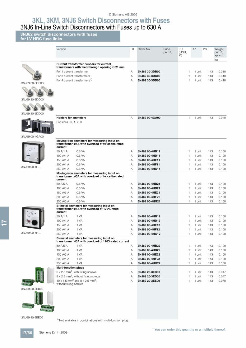
3KL, 3KM, 3NJ6 Switch Disconnectors with Fuses3NJ6 In-Line Switch Disconnectors with Fuses up to 630 A3NJ62 switch disconnectors with fusesfor LV HRC fuse links
17/66 Siemens LV 1 · 2009* You can order this quantity or a multiple thereof.
17
Version DT Order No. Price per PU
PU(UNIT, M)
PS* PG Weight per PU approx.
kg
3NJ69 30-3DB00
3NJ69 30-3DC00
3NJ69 30-3DD00
Current transformer busbars for current transformers with feed-through opening 21 mm
For 1 current transformer A 3NJ69 30-3DB00 1 1 unit 143 0.210
For 3 current transformers A 3NJ69 30-3DC00 1 1 unit 143 0.310
For 4 current transformers1) A 3NJ69 30-3DD00 1 1 unit 143 0.410
3NJ69 00-4GA00
Holders for ammeters
For sizes 00, 1, 2, 3
A 3NJ69 00-4GA00 1 1 unit 143 0.040
3NJ69 00-4H...
Moving-iron ammeters for measuring input on transformer x/1A with overload of twice the rated current
50 A/1 A 0.6 VA A 3NJ69 00-4HB11 1 1 unit 143 0.100
100 A/1 A 0.6 VA A 3NJ69 00-4HD11 1 1 unit 143 0.100
150 A/1 A 0.6 VA A 3NJ69 00-4HE11 1 1 unit 143 0.100
200 A/1 A 0.6 VA A 3NJ69 00-4HF11 1 1 unit 143 0.100
250 A/1 A 0.6 VA A 3NJ69 00-4HG11 1 1 unit 143 0.100
Moving-iron ammeters for measuring input on transformer x/5A with overload of twice the rated current
50 A/5 A 0.6 VA A 3NJ69 00-4HB21 1 1 unit 143 0.100
100 A/5 A 0.6 VA A 3NJ69 00-4HD21 1 1 unit 143 0.100
150 A/5 A 0.6 VA A 3NJ69 00-4HE21 1 1 unit 143 0.100
200 A/5 A 0.6 VA A 3NJ69 00-4HF21 1 1 unit 143 0.100
250 A/5 A 0.6 VA A 3NJ69 00-4HG21 1 1 unit 143 0.100
3NJ69 00-4H...
Bi-metal ammeters for measuring input on transformer x/1A with overload of 120% rated current
50 A/1 A 1 VA A 3NJ69 00-4HB12 1 1 unit 143 0.100
100 A/1 A 1 VA A 3NJ69 00-4HD12 1 1 unit 143 0.100
150 A/1 A 1 VA A 3NJ69 00-4HE12 1 1 unit 143 0.100
200 A/1 A 1 VA A 3NJ69 00-4HF12 1 1 unit 143 0.100
250 A/1 A 1 VA A 3NJ69 00-4HG12 1 1 unit 143 0.100
Bi-metal ammeters for measuring input on transformer x/5A with overload of 120% rated current
50 A/5 A 1 VA A 3NJ69 00-4HB22 1 1 unit 143 0.100
100 A/5 A 1 VA A 3NJ69 00-4HD22 1 1 unit 143 0.100
150 A/5 A 1 VA A 3NJ69 00-4HE22 1 1 unit 143 0.100
200 A/5 A 1 VA A 3NJ69 00-4HF22 1 1 unit 143 0.100
250 A/5 A 1 VA A 3NJ69 00-4HG22 1 1 unit 143 0.100
3NJ69 20-3EB00
3NJ69 40-3EE00
Multi-function plugs
6 x 2.5 mm2, with fixing screws A 3NJ69 20-3EB00 1 1 unit 143 0.047
8 x 2.5 mm2, without fixing screws A 3NJ69 20-3ED00 1 1 unit 143 0.047
10 x 1.5 mm2 and 8 x 2.5 mm2, without fixing screws
A 3NJ69 20-3EE00 1 1 unit 143 0.070
1) Not available in combinations with multi-function plug.
© Siemens AG 2009
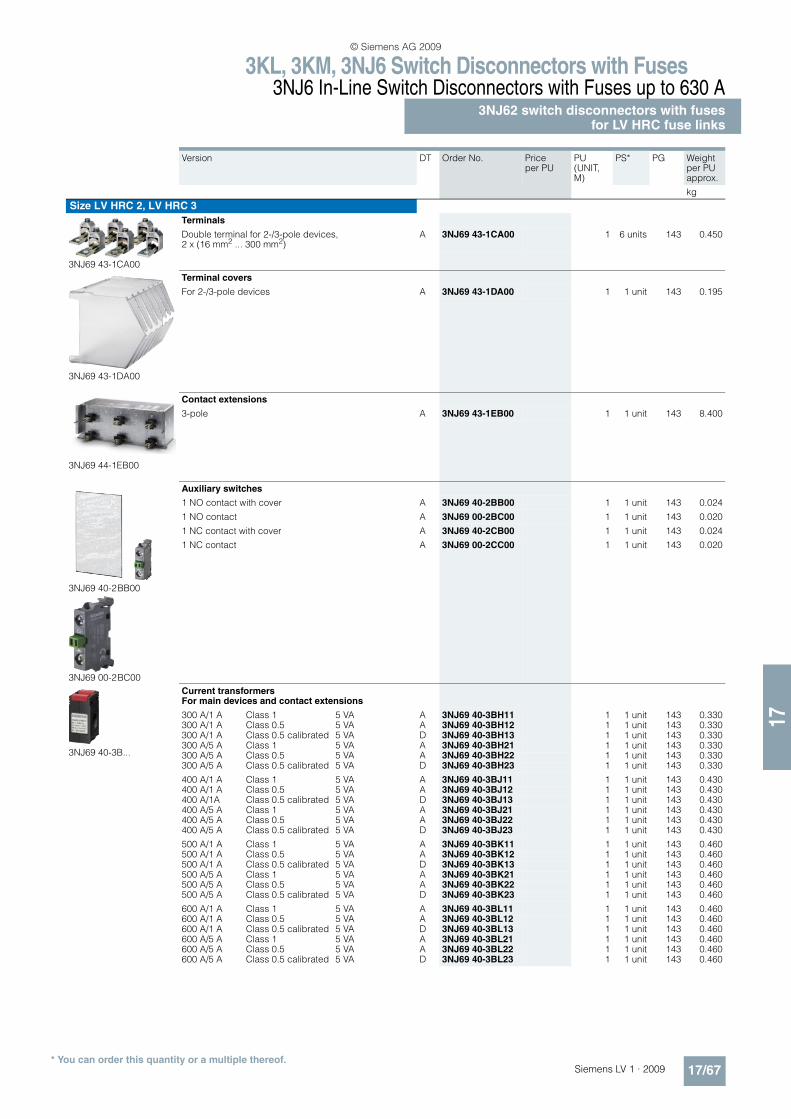
3KL, 3KM, 3NJ6 Switch Disconnectors with Fuses3NJ6 In-Line Switch Disconnectors with Fuses up to 630 A
3NJ62 switch disconnectors with fusesfor LV HRC fuse links
17/67Siemens LV 1 · 2009* You can order this quantity or a multiple thereof.
17
Version DT Order No. Price per PU
PU(UNIT, M)
PS* PG Weight per PU approx.
kg
Size LV HRC 2, LV HRC 3
3NJ69 43-1CA00
Terminals
Double terminal for 2-/3-pole devices, 2 x (16 mm2 ... 300 mm2)
A 3NJ69 43-1CA00 1 6 units 143 0.450
3NJ69 43-1DA00
Terminal covers
For 2-/3-pole devices A 3NJ69 43-1DA00 1 1 unit 143 0.195
3NJ69 44-1EB00
Contact extensions
3-pole A 3NJ69 43-1EB00 1 1 unit 143 8.400
3NJ69 40-2BB00
3NJ69 00-2BC00
Auxiliary switches
1 NO contact with cover A 3NJ69 40-2BB00 1 1 unit 143 0.024
1 NO contact A 3NJ69 00-2BC00 1 1 unit 143 0.020
1 NC contact with cover A 3NJ69 40-2CB00 1 1 unit 143 0.024
1 NC contact A 3NJ69 00-2CC00 1 1 unit 143 0.020
3NJ69 40-3B...
Current transformers For main devices and contact extensions
300 A/1 A Class 1 5 VA A 3NJ69 40-3BH11 1 1 unit 143 0.330300 A/1 A Class 0.5 5 VA A 3NJ69 40-3BH12 1 1 unit 143 0.330300 A/1 A Class 0.5 calibrated 5 VA D 3NJ69 40-3BH13 1 1 unit 143 0.330300 A/5 A Class 1 5 VA A 3NJ69 40-3BH21 1 1 unit 143 0.330300 A/5 A Class 0.5 5 VA A 3NJ69 40-3BH22 1 1 unit 143 0.330300 A/5 A Class 0.5 calibrated 5 VA D 3NJ69 40-3BH23 1 1 unit 143 0.330
400 A/1 A Class 1 5 VA A 3NJ69 40-3BJ11 1 1 unit 143 0.430400 A/1 A Class 0.5 5 VA A 3NJ69 40-3BJ12 1 1 unit 143 0.430400 A/1A Class 0.5 calibrated 5 VA D 3NJ69 40-3BJ13 1 1 unit 143 0.430400 A/5 A Class 1 5 VA A 3NJ69 40-3BJ21 1 1 unit 143 0.430400 A/5 A Class 0.5 5 VA A 3NJ69 40-3BJ22 1 1 unit 143 0.430400 A/5 A Class 0.5 calibrated 5 VA D 3NJ69 40-3BJ23 1 1 unit 143 0.430
500 A/1 A Class 1 5 VA A 3NJ69 40-3BK11 1 1 unit 143 0.460500 A/1 A Class 0.5 5 VA A 3NJ69 40-3BK12 1 1 unit 143 0.460500 A/1 A Class 0.5 calibrated 5 VA D 3NJ69 40-3BK13 1 1 unit 143 0.460500 A/5 A Class 1 5 VA A 3NJ69 40-3BK21 1 1 unit 143 0.460500 A/5 A Class 0.5 5 VA A 3NJ69 40-3BK22 1 1 unit 143 0.460500 A/5 A Class 0.5 calibrated 5 VA D 3NJ69 40-3BK23 1 1 unit 143 0.460
600 A/1 A Class 1 5 VA A 3NJ69 40-3BL11 1 1 unit 143 0.460600 A/1 A Class 0.5 5 VA A 3NJ69 40-3BL12 1 1 unit 143 0.460600 A/1 A Class 0.5 calibrated 5 VA D 3NJ69 40-3BL13 1 1 unit 143 0.460600 A/5 A Class 1 5 VA A 3NJ69 40-3BL21 1 1 unit 143 0.460600 A/5 A Class 0.5 5 VA A 3NJ69 40-3BL22 1 1 unit 143 0.460600 A/5 A Class 0.5 calibrated 5 VA D 3NJ69 40-3BL23 1 1 unit 143 0.460
© Siemens AG 2009
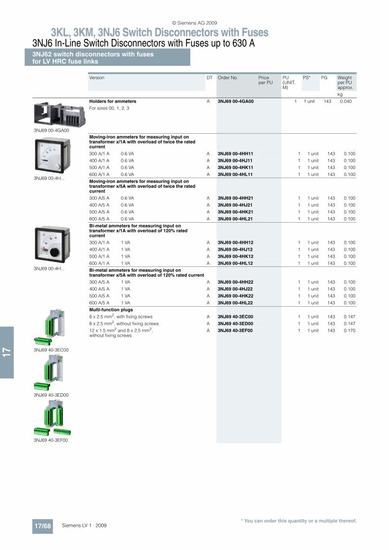
3KL, 3KM, 3NJ6 Switch Disconnectors with Fuses3NJ6 In-Line Switch Disconnectors with Fuses up to 630 A3NJ62 switch disconnectors with fusesfor LV HRC fuse links
17/68 Siemens LV 1 · 2009* You can order this quantity or a multiple thereof.
17
Version DT Order No. Price per PU
PU(UNIT, M)
PS* PG Weight per PU approx.
kg
3NJ69 00-4GA00
Holders for ammeters
For sizes 00, 1, 2, 3
A 3NJ69 00-4GA00 1 1 unit 143 0.040
3NJ69 00-4H...
Moving-iron ammeters for measuring input on transformer x/1A with overload of twice the rated current
300 A/1 A 0.6 VA A 3NJ69 00-4HH11 1 1 unit 143 0.100
400 A/1 A 0.6 VA A 3NJ69 00-4HJ11 1 1 unit 143 0.100
500 A/1 A 0.6 VA A 3NJ69 00-4HK11 1 1 unit 143 0.100
600 A/1 A 0.6 VA A 3NJ69 00-4HL11 1 1 unit 143 0.100
Moving-iron ammeters for measuring input on transformer x/5A with overload of twice the rated current
300 A/5 A 0.6 VA A 3NJ69 00-4HH21 1 1 unit 143 0.100
400 A/5 A 0.6 VA A 3NJ69 00-4HJ21 1 1 unit 143 0.100
500 A/5 A 0.6 VA A 3NJ69 00-4HK21 1 1 unit 143 0.100
600 A/5 A 0.6 VA A 3NJ69 00-4HL21 1 1 unit 143 0.100
3NJ69 00-4H...
Bi-metal ammeters for measuring input on transformer x/1A with overload of 120% rated current
300 A/1 A 1 VA A 3NJ69 00-4HH12 1 1 unit 143 0.100
400 A/1 A 1 VA A 3NJ69 00-4HJ12 1 1 unit 143 0.100
500 A/1 A 1 VA A 3NJ69 00-4HK12 1 1 unit 143 0.100
600 A/1 A 1 VA A 3NJ69 00-4HL12 1 1 unit 143 0.100
Bi-metal ammeters for measuring input on transformer x/5A with overload of 120% rated current
300 A/5 A 1 VA A 3NJ69 00-4HH22 1 1 unit 143 0.100
400 A/5 A 1 VA A 3NJ69 00-4HJ22 1 1 unit 143 0.100
500 A/5 A 1 VA A 3NJ69 00-4HK22 1 1 unit 143 0.100
600 A/5 A 1 VA A 3NJ69 00-4HL22 1 1 unit 143 0.100
3NJ69 40-3EC00
3NJ69 40-3ED00
3NJ69 40-3EF00
Multi-function plugs
8 x 2.5 mm2, with fixing screws A 3NJ69 40-3EC00 1 1 unit 143 0.147
8 x 2.5 mm2, without fixing screws A 3NJ69 40-3ED00 1 1 unit 143 0.147
12 x 1.5 mm2 and 8 x 2.5 mm2, without fixing screws
A 3NJ69 40-3EF00 1 1 unit 143 0.170
© Siemens AG 2009
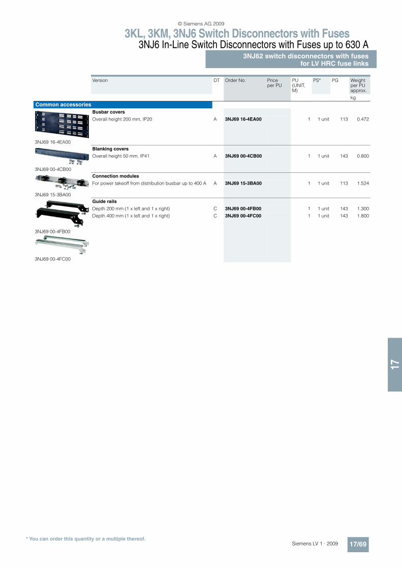
3KL, 3KM, 3NJ6 Switch Disconnectors with Fuses3NJ6 In-Line Switch Disconnectors with Fuses up to 630 A
3NJ62 switch disconnectors with fusesfor LV HRC fuse links
17/69Siemens LV 1 · 2009* You can order this quantity or a multiple thereof.
17
Version DT Order No. Price per PU
PU(UNIT, M)
PS* PG Weight per PU approx.
kg
Common accessories
3NJ69 16-4EA00
Busbar covers
Overall height 200 mm, IP20 A 3NJ69 16-4EA00 1 1 unit 113 0.472
3NJ69 00-4CB00
Blanking covers
Overall height 50 mm, IP41 A 3NJ69 00-4CB00 1 1 unit 143 0.800
3NJ69 15-3BA00
Connection modules
For power takeoff from distribution busbar up to 400 A A 3NJ69 15-3BA00 1 1 unit 113 1.524
3NJ69 00-4FB00
3NJ69 00-4FC00
Guide rails
Depth 200 mm (1 x left and 1 x right) C 3NJ69 00-4FB00 1 1 unit 143 1.300
Depth 400 mm (1 x left and 1 x right) C 3NJ69 00-4FC00 1 1 unit 143 1.800
© Siemens AG 2009
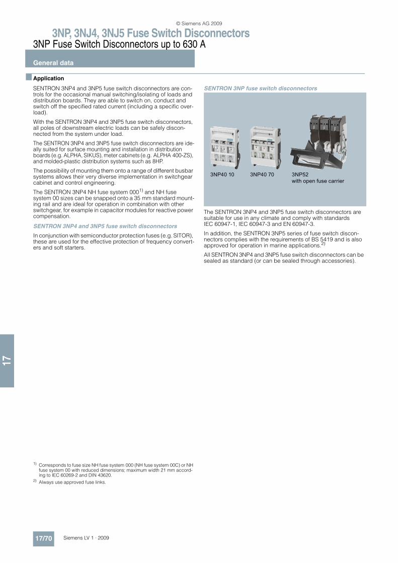
3NP, 3NJ4, 3NJ5 Fuse Switch Disconnectors3NP Fuse Switch Disconnectors up to 630 A
General data
17/70 Siemens LV 1 · 2009
17
n Application
SENTRON 3NP4 and 3NP5 fuse switch disconnectors are con-trols for the occasional manual switching/isolating of loads and distribution boards. They are able to switch on, conduct and switch off the specified rated current (including a specific over-load).
With the SENTRON 3NP4 and 3NP5 fuse switch disconnectors, all poles of downstream electric loads can be safely discon-nected from the system under load.
The SENTRON 3NP4 and 3NP5 fuse switch disconnectors are ide-ally suited for surface mounting and installation in distribution boards (e.g. ALPHA, SIKUS), meter cabinets (e.g. ALPHA 400-ZS), and molded-plastic distribution systems such as 8HP.
The possibility of mounting them onto a range of different busbar systems allows their very diverse implementation in switchgear cabinet and control engineering.
The SENTRON 3NP4 NH fuse system 0001) and NH fuse system 00 sizes can be snapped onto a 35 mm standard mount-ing rail and are ideal for operation in combination with other switchgear, for example in capacitor modules for reactive power compensation.
SENTRON 3NP4 and 3NP5 fuse switch disconnectors
In conjunction with semiconductor protection fuses (e.g. SITOR), these are used for the effective protection of frequency convert-ers and soft starters.
SENTRON 3NP fuse switch disconnectors
The SENTRON 3NP4 and 3NP5 fuse switch disconnectors are suitable for use in any climate and comply with standards IEC 60947-1, IEC 60947-3 and EN 60947-3.
In addition, the SENTRON 3NP5 series of fuse switch discon-nectors complies with the requirements of BS 5419 and is also approved for operation in marine applications.2)
All SENTRON 3NP4 and 3NP5 fuse switch disconnectors can be sealed as standard (or can be sealed through accessories).
1) Corresponds to fuse size NH fuse system 000 (NH fuse system 00C) or NH fuse system 00 with reduced dimensions; maximum width 21 mm accord-ing to IEC 60269-2 and DIN 43620.
2) Always use approved fuse links.
© Siemens AG 2009
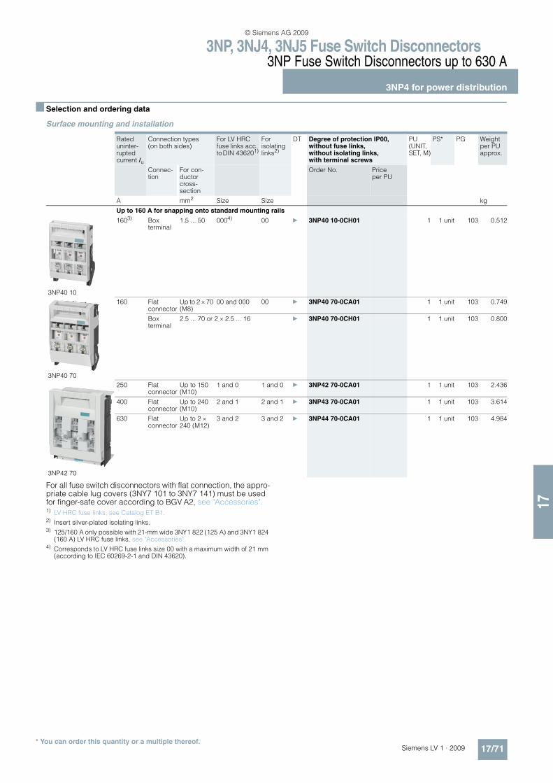
3NP, 3NJ4, 3NJ5 Fuse Switch Disconnectors3NP Fuse Switch Disconnectors up to 630 A
3NP4 for power distribution
17/71Siemens LV 1 · 2009* You can order this quantity or a multiple thereof.
17
n Selection and ordering data
Surface mounting and installation
For all fuse switch disconnectors with flat connection, the appro-priate cable lug covers (3NY7 101 to 3NY7 141) must be used for finger-safe cover according to BGV A2, see "Accessories". 1) LV HRC fuse links, see Catalog ET B1.2) Insert silver-plated isolating links.3) 125/160 A only possible with 21-mm wide 3NY1 822 (125 A) and 3NY1 824
(160 A) LV HRC fuse links, see "Accessories".4) Corresponds to LV HRC fuse links size 00 with a maximum width of 21 mm
(according to IEC 60269-2-1 and DIN 43620).
Rated uninter-rupted current Iu
Connection types (on both sides)
For LV HRC fuse links acc. to DIN 436201)
For isolating links2)
DT Degree of protection IP00, without fuse links, without isolating links, with terminal screws
PU (UNIT, SET, M)
PS* PG Weight per PU approx.
Connec-tion
For con-ductor cross-section
Order No. Price per PU
A mm2 Size Size kg
Up to 160 A for snapping onto standard mounting rails
3NP40 10
1603) Box terminal
1.5 ... 50 0004) 00 } 3NP40 10-0CH01 1 1 unit 103 0.512
3NP40 70
160 Flat connector
Up to 2 × 70 (M8)
00 and 000 00 } 3NP40 70-0CA01 1 1 unit 103 0.749
Box terminal
2.5 ... 70 or 2 × 2.5 ... 16 } 3NP40 70-0CH01 1 1 unit 103 0.800
3NP42 70
250 Flat connector
Up to 150 (M10)
1 and 0 1 and 0 } 3NP42 70-0CA01 1 1 unit 103 2.436
400 Flat connector
Up to 240 (M10)
2 and 1 2 and 1 } 3NP43 70-0CA01 1 1 unit 103 3.614
630 Flat connector
Up to 2 × 240 (M12)
3 and 2 3 and 2 } 3NP44 70-0CA01 1 1 unit 103 4.984
© Siemens AG 2009
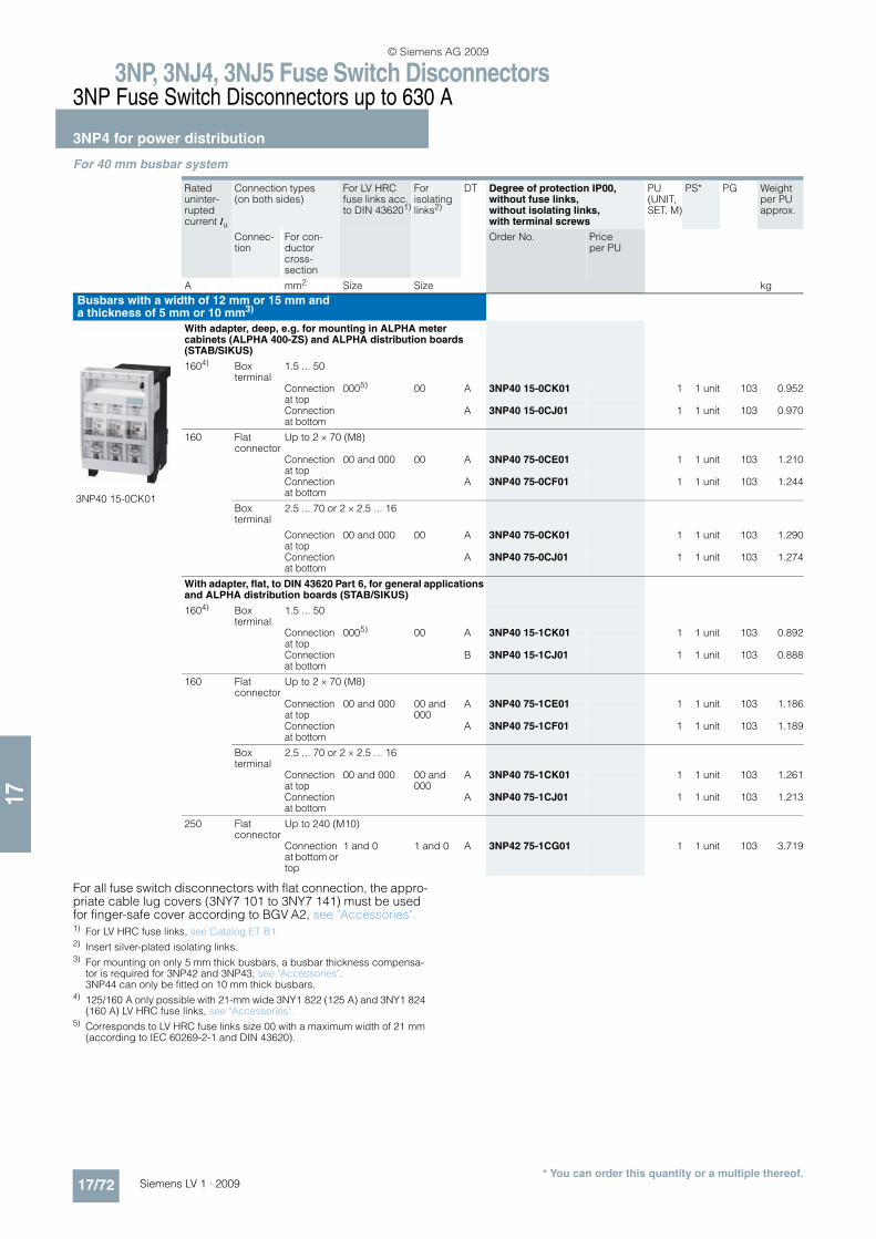
3NP, 3NJ4, 3NJ5 Fuse Switch Disconnectors3NP Fuse Switch Disconnectors up to 630 A
3NP4 for power distribution
17/72 Siemens LV 1 · 2009* You can order this quantity or a multiple thereof.
17
For 40 mm busbar system
For all fuse switch disconnectors with flat connection, the appro-priate cable lug covers (3NY7 101 to 3NY7 141) must be used for finger-safe cover according to BGV A2, see "Accessories". 1) For LV HRC fuse links, see Catalog ET B1.2) Insert silver-plated isolating links.3) For mounting on only 5 mm thick busbars, a busbar thickness compensa-
tor is required for 3NP42 and 3NP43; see "Accessories". 3NP44 can only be fitted on 10 mm thick busbars.
4) 125/160 A only possible with 21-mm wide 3NY1 822 (125 A) and 3NY1 824 (160 A) LV HRC fuse links, see "Accessories".
5) Corresponds to LV HRC fuse links size 00 with a maximum width of 21 mm (according to IEC 60269-2-1 and DIN 43620).
Rated uninter-rupted current Iu
Connection types (on both sides)
For LV HRC fuse links acc. to DIN 436201)
For isolating links2)
DT Degree of protection IP00, without fuse links, without isolating links, with terminal screws
PU (UNIT, SET, M)
PS* PG Weight per PU approx.
Connec-tion
For con-ductor cross-section
Order No. Price per PU
A mm2 Size Size kg
Busbars with a width of 12 mm or 15 mm anda thickness of 5 mm or 10 mm3)
With adapter, deep, e.g. for mounting in ALPHA meter cabinets (ALPHA 400-ZS) and ALPHA distribution boards (STAB/SIKUS)
3NP40 15-0CK01
1604) Box terminal
1.5 ... 50
Connection at top
0005) 00 A 3NP40 15-0CK01 1 1 unit 103 0.952
Connection at bottom
A 3NP40 15-0CJ01 1 1 unit 103 0.970
160 Flat connector
Up to 2 × 70 (M8)
Connection at top
00 and 000 00 A 3NP40 75-0CE01 1 1 unit 103 1.210
Connection at bottom
A 3NP40 75-0CF01 1 1 unit 103 1.244
Box terminal
2.5 ... 70 or 2 × 2.5 ... 16
Connection at top
00 and 000 00 A 3NP40 75-0CK01 1 1 unit 103 1.290
Connection at bottom
A 3NP40 75-0CJ01 1 1 unit 103 1.274
With adapter, flat, to DIN 43620 Part 6, for general applications and ALPHA distribution boards (STAB/SIKUS)
1604) Box terminal
1.5 ... 50
Connection at top
0005) 00 A 3NP40 15-1CK01 1 1 unit 103 0.892
Connection at bottom
B 3NP40 15-1CJ01 1 1 unit 103 0.888
160 Flat connector
Up to 2 × 70 (M8)
Connection at top
00 and 000 00 and 000
A 3NP40 75-1CE01 1 1 unit 103 1.186
Connection at bottom
A 3NP40 75-1CF01 1 1 unit 103 1.189
Box terminal
2.5 ... 70 or 2 × 2.5 ... 16
Connection at top
00 and 000 00 and 000
A 3NP40 75-1CK01 1 1 unit 103 1.261
Connection at bottom
A 3NP40 75-1CJ01 1 1 unit 103 1.213
250 Flat connector
Up to 240 (M10)
Connection at bottom or top
1 and 0 1 and 0 A 3NP42 75-1CG01 1 1 unit 103 3.719
© Siemens AG 2009
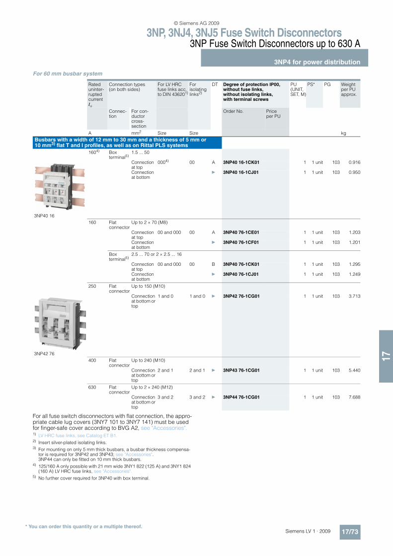
3NP, 3NJ4, 3NJ5 Fuse Switch Disconnectors3NP Fuse Switch Disconnectors up to 630 A
3NP4 for power distribution
17/73Siemens LV 1 · 2009* You can order this quantity or a multiple thereof.
17
For 60 mm busbar system
For all fuse switch disconnectors with flat connection, the appro-priate cable lug covers (3NY7 101 to 3NY7 141) must be used for finger-safe cover according to BVG A2, see "Accessories".1) LV HRC fuse links, see Catalog ET B1.2) Insert silver-plated isolating links.3) For mounting on only 5 mm thick busbars, a busbar thickness compensa-
tor is required for 3NP42 and 3NP43; see "Accessories". 3NP44 can only be fitted on 10 mm thick busbars.
4) 125/160 A only possible with 21 mm wide 3NY1 822 (125 A) and 3NY1 824 (160 A) LV HRC fuse links, see "Accessories".
5) No further cover required for 3NP40 with box terminal.
Rated uninter-rupted current Iu
Connection types (on both sides)
For LV HRC fuse links acc. to DIN 436201)
For isolating links2)
DT Degree of protection IP00, without fuse links, without isolating links, with terminal screws
PU (UNIT, SET, M)
PS* PG Weight per PU approx.
Connec-tion
For con-ductor cross-section
Order No. Price per PU
A mm2 Size Size kg
Busbars with a width of 12 mm to 30 mm and a thickness of 5 mm or 10 mm3) flat T and I profiles, as well as on Rittal PLS systems
1604) Box terminal5)
1.5 ... 50
3NP40 16
Connection at top
0004) 00 A 3NP40 16-1CK01 1 1 unit 103 0.916
Connection at bottom
} 3NP40 16-1CJ01 1 1 unit 103 0.950
160 Flat connector
Up to 2 × 70 (M8)
Connection at top
00 and 000 00 A 3NP40 76-1CE01 1 1 unit 103 1.203
Connection at bottom
} 3NP40 76-1CF01 1 1 unit 103 1.201
Box terminal5)
2.5 ... 70 or 2 × 2.5 ... 16
Connection at top
00 and 000 00 B 3NP40 76-1CK01 1 1 unit 103 1.295
Connection at bottom
} 3NP40 76-1CJ01 1 1 unit 103 1.249
250 Flat connector
Up to 150 (M10)
3NP42 76
Connection at bottom or top
1 and 0 1 and 0 } 3NP42 76-1CG01 1 1 unit 103 3.713
400 Flat connector
Up to 240 (M10)
Connection at bottom or top
2 and 1 2 and 1 } 3NP43 76-1CG01 1 1 unit 103 5.440
630 Flat connector
Up to 2 × 240 (M12)
Connection at bottom or top
3 and 2 3 and 2 } 3NP44 76-1CG01 1 1 unit 103 7.688
© Siemens AG 2009
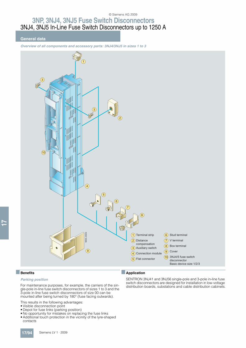
3NP, 3NJ4, 3NJ5 Fuse Switch Disconnectors3NJ4, 3NJ5 In-Line Fuse Switch Disconnectors up to 1250 A
General data
17/94 Siemens LV 1 · 2009
17
Overview of all components and accessory parts: 3NJ4/3NJ5 in sizes 1 to 3
n Benefits
Parking position
For maintenance purposes, for example, the carriers of the sin-gle-pole in-line fuse switch disconnectors of sizes 1 to 3 and the 3-pole in-line fuse switch disconnectors of size 00 can be mounted after being turned by 180° (fuse facing outwards).
This results in the following advantages:• Visible disconnection point• Depot for fuse links (parking position)• No opportunity for mistakes on replacing the fuse links• Additional touch protection in the vicinity of the lyre-shaped
contacts
n Application
SENTRON 3NJ41 and 3NJ56 single-pole and 3-pole in-line fuse switch disconnectors are designed for installation in low-voltage distribution boards, substations and cable distribution cabinets.
4
7
6
8
3
3
1
10
2
9
5
Terminal strip
Distance
compensation
Auxiliary switch
Connection module
Flat connector
Stud terminal
V terminal
Box terminal
Cover
3NJ4/5 fuse switch
disconnector
Basic device size 1/2/3
1
2
3
4
5
6
7
8
9
10
© Siemens AG 2009
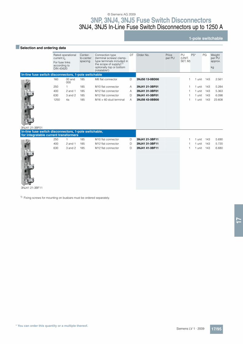
3NP, 3NJ4, 3NJ5 Fuse Switch Disconnectors3NJ4, 3NJ5 In-Line Fuse Switch Disconnectors up to 1250 A
1-pole switchable
17/95Siemens LV 1 · 2009* You can order this quantity or a multiple thereof.
17
n Selection and ordering data
1) Fixing screws for mounting on busbars must be ordered separately.
Rated operational current Ie
Center-to-center spacing
Connection type (terminal screws/ clamp-type terminals included in the scope of supply)1) optionally top or bottom (rotatable!)
DT Order No. Price per PU
PU (UNIT, SET, M)
PS* PG Weight per PUapprox.
kg
For fuse links according to DIN 43620
In-line fuse switch disconnectors, 1-pole switchable
3NJ41 21-3BF01
160 00 and 000
185 M8 flat connector D 3NJ50 13-0BD00 1 1 unit 143 2.561
250 1 185 M10 flat connector A 3NJ41 21-3BF01 1 1 unit 143 5.284
400 2 and 1 185 M12 flat connector A 3NJ41 31-3BF01 1 1 unit 143 5.363
630 3 and 2 185 M12 flat connector D 3NJ41 41-3BF01 1 1 unit 143 6.098
1250 4a 185 M16 × 60 stud terminal A 3NJ56 43-0BB00 1 1 unit 143 23.608
In-line fuse switch disconnectors, 1-pole switchable, for integratable current transformers
3NJ41 21-3BF11
250 1 185 M10 flat connector D 3NJ41 21-3BF11 1 1 unit 143 5.690
400 2 and 1 185 M12 flat connector D 3NJ41 31-3BF11 1 1 unit 143 5.720
630 3 and 2 185 M12 flat connector D 3NJ41 41-3BF11 1 1 unit 143 6.680
© Siemens AG 2009
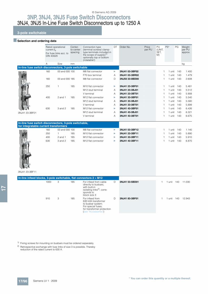
3NP, 3NJ4, 3NJ5 Fuse Switch Disconnectors3NJ4, 3NJ5 In-Line Fuse Switch Disconnectors up to 1250 A
3-pole switchable
17/96 Siemens LV 1 · 2009* You can order this quantity or a multiple thereof.
17
n Selection and ordering data
1) Fixing screws for mounting on busbars must be ordered separately.2) Retrospective exchange with fuse links of size 3 is possible. Thereby
reduction of the rated current to 630 A.
Rated operational current Ie
Center-to-center spacing
Connection type (terminal screws/ clamp-type terminals included in the scope of supply)1) optionally top or bottom (rotatable!)
DT Order No. Price per PU
PU (UNIT, SET, M)
PS* PG Weight per PU approx.For fuse links acc. to
DIN 43620
A Size mm kg
In-line fuse switch disconnectors, 3-pole switchable
3NJ41 23-3BF01
160 00 and 000 100 M8 flat connector } 3NJ41 03-3BF02 1 1 unit 143 1.400
F70 box terminal A 3NJ41 03-3BR02 1 1 unit 143 1.479
160 00 and 000 185 M8 flat connector D 3NJ50 33-0BD00 1 1 unit 143 2.608
250 1 185 M10 flat connector } 3NJ41 23-3BF01 1 1 unit 143 5.481
M12 stud terminal A 3NJ41 23-3BJ01 1 1 unit 143 5.512
V terminal A 3NJ41 23-3BT01 1 1 unit 143 5.908
400 2 and 1 185 M12 flat connector } 3NJ41 33-3BF01 1 1 unit 143 5.540
M12 stud terminal A 3NJ41 33-3BJ01 1 1 unit 143 5.580
V terminal A 3NJ41 33-3BT01 1 1 unit 143 5.899
630 3 and 2 185 M12 flat connector } 3NJ41 43-3BF01 1 1 unit 143 6.426
M12 stud terminal A 3NJ41 43-3BJ01 1 1 unit 143 6.321
V terminal A 3NJ41 43-3BT01 1 1 unit 143 6.675
In-line fuse switch disconnectors, 3-pole switchable, for integratable current transformers
3NJ41 23-3BF11
160 00 and 000 100 M8 flat connector } 3NJ41 03-3BF12 1 1 unit 143 1.140
250 1 185 M10 flat connector } 3NJ41 23-3BF11 1 1 unit 143 5.890
400 2 and 1 185 M12 flat connector } 3NJ41 33-3BF11 1 1 unit 143 5.910
630 3 and 2 185 M12 flat connector } 3NJ41 43-3BF11 1 1 unit 143 6.870
In-line infeed blocks, 3-pole switchable, flat connectors 2 × M12
1000 3 185 For infeed from cable directly to busbars, with built-in isolating links2), corre-sponds to block size 3
D 3NJ41 53-5BD01 1 1 unit 143 11.030
910 3 185 For infeed from 630 kVA transformer to busbar system; For special fuses, for transformer protection (see "Accessories")
D 3NJ41 83-3BF01 1 1 unit 143 12.943
© Siemens AG 2009
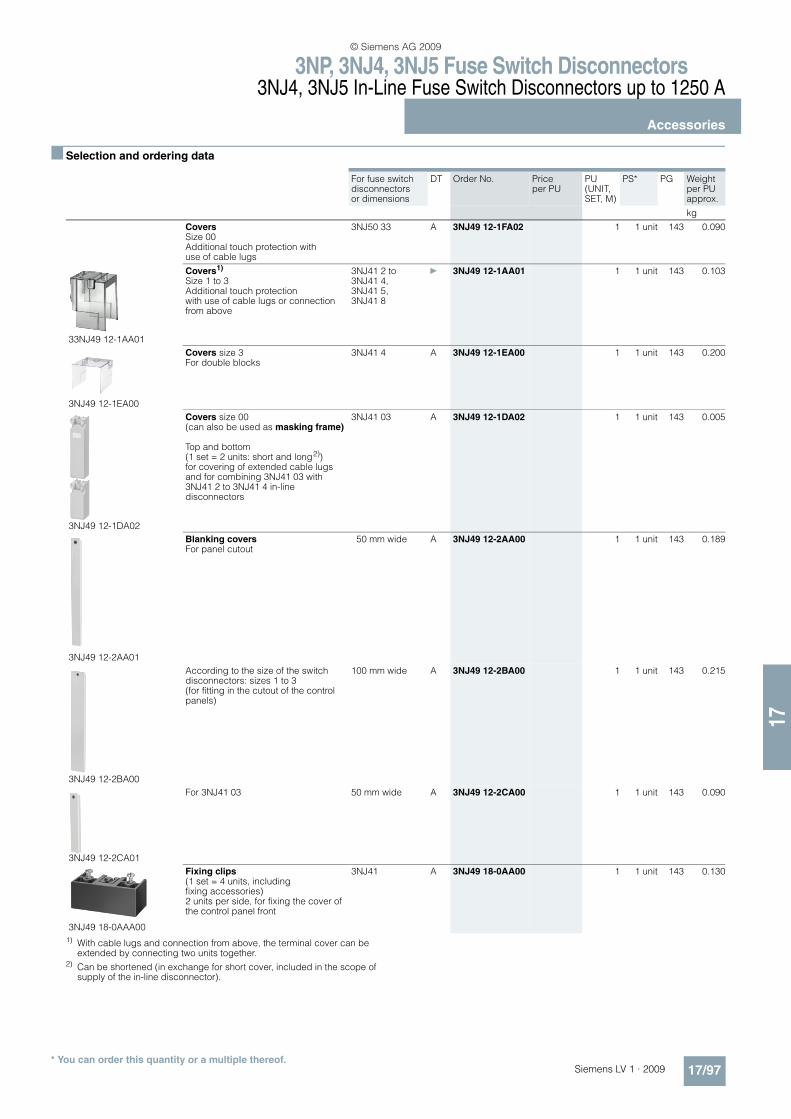
3NP, 3NJ4, 3NJ5 Fuse Switch Disconnectors3NJ4, 3NJ5 In-Line Fuse Switch Disconnectors up to 1250 A
Accessories
17/97Siemens LV 1 · 2009* You can order this quantity or a multiple thereof.
17
n Selection and ordering data
1) With cable lugs and connection from above, the terminal cover can be extended by connecting two units together.
2) Can be shortened (in exchange for short cover, included in the scope of supply of the in-line disconnector).
For fuse switch disconnectors or dimensions
DT Order No. Price per PU
PU (UNIT, SET, M)
PS* PG Weight per PU approx.
kg
Covers
Size 00 Additional touch protection with use of cable lugs
3NJ50 33 A 3NJ49 12-1FA02 1 1 unit 143 0.090
33NJ49 12-1AA01
Covers1) Size 1 to 3 Additional touch protection with use of cable lugs or connection from above
3NJ41 2 to3NJ41 4,3NJ41 5,3NJ41 8
} 3NJ49 12-1AA01 1 1 unit 143 0.103
3NJ49 12-1EA00
Covers size 3 For double blocks
3NJ41 4 A 3NJ49 12-1EA00 1 1 unit 143 0.200
3NJ49 12-1DA02
Covers size 00 (can also be used as masking frame)
Top and bottom (1 set = 2 units: short and long2))for covering of extended cable lugs and for combining 3NJ41 03 with 3NJ41 2 to 3NJ41 4 in-line disconnectors
3NJ41 03 A 3NJ49 12-1DA02 1 1 unit 143 0.005
3NJ49 12-2AA01
Blanking covers For panel cutout
50 mm wide A 3NJ49 12-2AA00 1 1 unit 143 0.189
3NJ49 12-2BA00
According to the size of the switch disconnectors: sizes 1 to 3 (for fitting in the cutout of the control panels)
100 mm wide A 3NJ49 12-2BA00 1 1 unit 143 0.215
3NJ49 12-2CA01
For 3NJ41 03 50 mm wide A 3NJ49 12-2CA00 1 1 unit 143 0.090
3NJ49 18-0AAA00
Fixing clips (1 set = 4 units, including fixing accessories) 2 units per side, for fixing the cover of the control panel front
3NJ41 A 3NJ49 18-0AA00 1 1 unit 143 0.130
© Siemens AG 2009
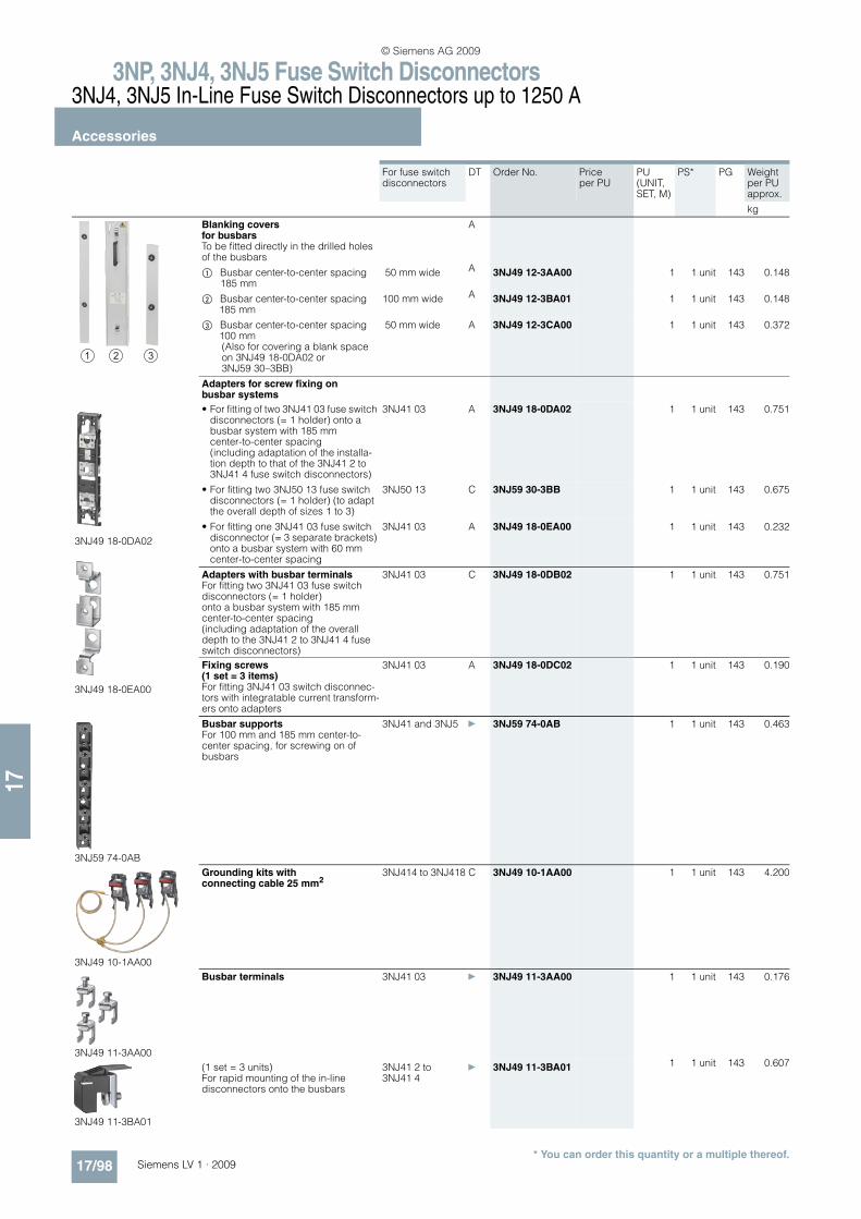
3NP, 3NJ4, 3NJ5 Fuse Switch Disconnectors3NJ4, 3NJ5 In-Line Fuse Switch Disconnectors up to 1250 A
Accessories
17/98 Siemens LV 1 · 2009* You can order this quantity or a multiple thereof.
17
For fuse switch disconnectors
DT Order No. Price per PU
PU (UNIT, SET, M)
PS* PG Weight per PU approx.
kg
Blanking covers for busbars To be fitted directly in the drilled holes of the busbars
A
$ Busbar center-to-center spacing 185 mm
50 mm wide A 3NJ49 12-3AA00 1 1 unit 143 0.148
% Busbar center-to-center spacing 185 mm
100 mm wide A 3NJ49 12-3BA01 1 1 unit 143 0.148
& Busbar center-to-center spacing 100 mm(Also for covering a blank space on 3NJ49 18-0DA02 or 3NJ59 30–3BB)
50 mm wide A 3NJ49 12-3CA00 1 1 unit 143 0.372
Adapters for screw fixing on busbar systems
3NJ49 18-0DA02
3NJ49 18-0EA00
• For fitting of two 3NJ41 03 fuse switch disconnectors (= 1 holder) onto a busbar system with 185 mm center-to-center spacing (including adaptation of the installa-tion depth to that of the 3NJ41 2 to 3NJ41 4 fuse switch disconnectors)
3NJ41 03 A 3NJ49 18-0DA02 1 1 unit 143 0.751
• For fitting two 3NJ50 13 fuse switch disconnectors (= 1 holder) (to adapt the overall depth of sizes 1 to 3)
3NJ50 13 C 3NJ59 30-3BB 1 1 unit 143 0.675
• For fitting one 3NJ41 03 fuse switch disconnector (= 3 separate brackets) onto a busbar system with 60 mm center-to-center spacing
3NJ41 03 A 3NJ49 18-0EA00 1 1 unit 143 0.232
Adapters with busbar terminalsFor fitting two 3NJ41 03 fuse switch disconnectors (= 1 holder) onto a busbar system with 185 mm center-to-center spacing (including adaptation of the overall depth to the 3NJ41 2 to 3NJ41 4 fuse switch disconnectors)
3NJ41 03 C 3NJ49 18-0DB02 1 1 unit 143 0.751
Fixing screws (1 set = 3 items)For fitting 3NJ41 03 switch disconnec-tors with integratable current transform-ers onto adapters
3NJ41 03 A 3NJ49 18-0DC02 1 1 unit 143 0.190
3NJ59 74-0AB
Busbar supports For 100 mm and 185 mm center-to-center spacing, for screwing on of busbars
3NJ41 and 3NJ5 } 3NJ59 74-0AB 1 1 unit 143 0.463
3NJ49 10-1AA00
Grounding kits with connecting cable 25 mm2
3NJ414 to 3NJ418 C 3NJ49 10-1AA00 1 1 unit 143 4.200
3NJ49 11-3AA00
Busbar terminals 3NJ41 03 } 3NJ49 11-3AA00 1 1 unit 143 0.176
3NJ49 11-3BA01
(1 set = 3 units) For rapid mounting of the in-line disconnectors onto the busbars
3NJ41 2 to 3NJ41 4
} 3NJ49 11-3BA01 1 1 unit 143 0.607
© Siemens AG 2009
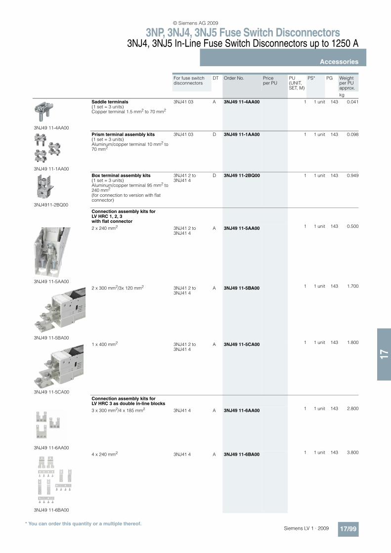
3NP, 3NJ4, 3NJ5 Fuse Switch Disconnectors3NJ4, 3NJ5 In-Line Fuse Switch Disconnectors up to 1250 A
Accessories
17/99Siemens LV 1 · 2009* You can order this quantity or a multiple thereof.
17
For fuse switch disconnectors
DT Order No. Price per PU
PU (UNIT, SET, M)
PS* PG Weight per PU approx.
kg
3NJ49 11-4AA00
Saddle terminals(1 set = 3 units) Copper terminal 1.5 mm2 to 70 mm2
3NJ41 03 A 3NJ49 11-4AA00 1 1 unit 143 0.041
3NJ49 11-1AA00
Prism terminal assembly kits (1 set = 3 units) Aluminum/copper terminal 10 mm2 to 70 mm2
3NJ41 03 D 3NJ49 11-1AA00 1 1 unit 143 0.098
3NJ4911-2BQ00
Box terminal assembly kits (1 set = 3 units) Aluminum/copper terminal 95 mm2 to 240 mm2 (for connection to version with flat connector)
3NJ41 2 to 3NJ41 4
D 3NJ49 11-2BQ00 1 1 unit 143 0.949
Connection assembly kits for LV HRC 1, 2, 3with flat connector
3NJ49 11-5AA00
2 x 240 mm2 3NJ41 2 to 3NJ41 4
A 3NJ49 11-5AA00 1 1 unit 143 0.500
3NJ49 11-5BA00
2 x 300 mm2/3x 120 mm2 3NJ41 2 to 3NJ41 4
A 3NJ49 11-5BA00 1 1 unit 143 1.700
3NJ49 11-5CA00
1 x 400 mm2 3NJ41 2 to 3NJ41 4
A 3NJ49 11-5CA00 1 1 unit 143 1.800
Connection assembly kits for LV HRC 3 as double in-line blocks
3NJ49 11-6AA00
3 x 300 mm2/4 x 185 mm2 3NJ41 4 A 3NJ49 11-6AA00 1 1 unit 143 2.800
3NJ49 11-6BA00
4 x 240 mm2 3NJ41 4 A 3NJ49 11-6BA00 1 1 unit 143 3.800
© Siemens AG 2009
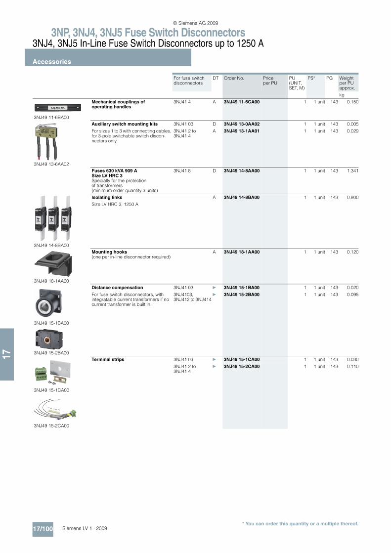
3NP, 3NJ4, 3NJ5 Fuse Switch Disconnectors3NJ4, 3NJ5 In-Line Fuse Switch Disconnectors up to 1250 A
Accessories
17/100 Siemens LV 1 · 2009* You can order this quantity or a multiple thereof.
17
For fuse switch disconnectors
DT Order No. Price per PU
PU (UNIT, SET, M)
PS* PG Weight per PU approx.
kg
3NJ49 11-6BA00
Mechanical couplings of operating handles
3NJ41 4 A 3NJ49 11-6CA00 1 1 unit 143 0.150
3NJ49 13-6AA02
Auxiliary switch mounting kits 3NJ41 03 D 3NJ49 13-0AA02 1 1 unit 143 0.005
For sizes 1 to 3 with connecting cables, for 3-pole switchable switch discon-nectors only
3NJ41 2 to 3NJ41 4
A 3NJ49 13-1AA01 1 1 unit 143 0.029
Fuses 630 kVA 909 A Size LV HRC 3Specially for the protection of transformers (minimum order quantity 3 units)
3NJ41 8 D 3NJ49 14-8AA00 1 1 unit 143 1.341
3NJ49 14-8BA00
Isolating links
Size LV HRC 3, 1250 A
A 3NJ49 14-8BA00 1 1 unit 143 0.800
3NJ49 18-1AA00
Mounting hooks (one per in-line disconnector required)
A 3NJ49 18-1AA00 1 1 unit 143 0.120
3NJ49 15-1BA00
3NJ49 15-2BA00
Distance compensation 3NJ41 03 } 3NJ49 15-1BA00 1 1 unit 143 0.020
For fuse switch disconnectors, with integratable current transformers if no current transformer is built in.
3NJ4103,3NJ412 to 3NJ414
} 3NJ49 15-2BA00 1 1 unit 143 0.095
3NJ49 15-1CA00
3NJ49 15-2CA00
Terminal strips 3NJ41 03 } 3NJ49 15-1CA00 1 1 unit 143 0.030
3NJ41 2 to 3NJ41 4
} 3NJ49 15-2CA00 1 1 unit 143 0.110
© Siemens AG 2009

3NP, 3NJ4, 3NJ5 Fuse Switch Disconnectors3NJ4, 3NJ5 In-Line Fuse Switch Disconnectors up to 1250 A
Accessories
17/101Siemens LV 1 · 2009* You can order this quantity or a multiple thereof.
17
For fuse switch disconnectors
DT Order No. Price per PU
PU (UNIT, SET, M)
PS* PG Weight per PU approx.
kg
Current transformers .../1 A
3NJ49 15-1FB20
100/1 A, Cl. 0.5, 1.5 VA 3NJ41 03 D 3NJ49 15-1EA10 1 1 unit 143 0.250100/1 A, Cl. 1, 2.0 VA 3NJ41 03 C 3NJ49 15-1EA20 1 1 unit 143 0.250150/1 A, Cl. 0.5, 2.5 VA 3NJ41 03 D 3NJ49 15-1FA10 1 1 unit 143 0.250150/1 A, Cl. 0.5 calibrated, 2.5 VA 3NJ41 03 D 3NJ49 15-1FA11 1 1 unit 143 0.250150/1 A, Cl. 1, 3.0 VA 3NJ41 03
}3NJ49 15-1FA20 1 1 unit 143 0.250
75/1 A, Cl. 1, 1.5 VA 3NJ41 2 to 3NJ41 4
D 3NJ49 15-2DA20 1 1 unit 143 0.190
100/1 A, Cl. 0.5, 1.5 VA 3NJ41 2 to 3NJ41 4
D 3NJ49 15-2EA10 1 1 unit 143 0.190
100/1 A, Cl. 1, 2.0 VA 3NJ41 2 to 3NJ41 4
D 3NJ49 15-2EA20 1 1 unit 143 0.190
150/1 A, Cl. 0.5, 2.5 VA 3NJ41 2 to 3NJ41 4
C 3NJ49 15-2FA10 1 1 unit 143 0.190
150/1 A, Cl. 1, 2.5 VA 3NJ41 2 to 3NJ41 4
D 3NJ49 15-2FA20 1 1 unit 143 0.190
250/1 A, Cl. 0.5, 2.5 VA 3NJ41 2 to 3NJ41 4
D 3NJ49 15-2GA10 1 1 unit 143 0.190
250/1 A, Cl. 0.5 calibrated, 2.5 VA 3NJ41 2 to 3NJ41 4
D 3NJ49 15-2GA11 1 1 unit 143 0.190
250/1 A, Cl. 1, 5.0 VA 3NJ41 2 to 3NJ41 4
} 3NJ49 15-2GA20 1 1 unit 143 0.190
3NJ49 15-2HA20
400/1 A, Cl. 0.5, 2.5 VA 3NJ41 2 to 3NJ41 4
D 3NJ49 15-2HA10 1 1 unit 143 0.190
400/1 A, Cl. 0.5 calibrated, 2.5 VA 3NJ41 2 to 3NJ41 4
D 3NJ49 15-2HA11 1 1 unit 143 0.190
400/1 A, Cl. 1, 5.0 VA 3NJ41 2 to 3NJ41 4
} 3NJ49 15-2HA20 1 1 unit 143 0.190
500/1 A, Cl. 0.5, 2.5 VA 3NJ41 2 to 3NJ41 4
D 3NJ49 15-2JA10 1 1 unit 143 0.190
500/1 A, Cl. 1, 5.0 VA 3NJ41 2 to 3NJ41 4
D 3NJ49 15-2JA20 1 1 unit 143 0.190
600/1 A, Cl. 0.5, 2.5 VA 3NJ41 2 to 3NJ41 4
D 3NJ49 15-2KA10 1 1 unit 143 0.190
600/1 A, Cl. 0.5 calibrated, 2.5 VA 3NJ41 2 to 3NJ41 4
D 3NJ49 15-2KA11 1 1 unit 143 0.190
600/1 A, Cl. 1, 5.0 VA 3NJ41 2 to 3NJ41 4
} 3NJ49 15-2KA20 1 1 unit 143 0.190
Current transformers .../5 A
100/5 A, Cl. 0.5, 1.0 VA 3NJ41 03 D 3NJ49 15-1EB10 1 1 unit 143 0.250
3NJ49 15-1FB20
100/5 A, Cl. 1, 1.5 VA 3NJ41 03 D 3NJ49 15-1EB20 1 1 unit 143 0.250150/5 A, Cl. 0.5, 1.5 VA 3NJ41 03 D 3NJ49 15-1FB10 1 1 unit 143 0.250150/5 A, Cl. 0.5 calibrated, 1.5 VA 3NJ41 03 D 3NJ49 15-1FB11 1 1 unit 143 0.250150/5 A, Cl. 1, 2.5 VA 3NJ41 03 } 3NJ49 15-1FB20 1 1 unit 143 0.25075/5 A, Cl. 1, 1.5 VA 3NJ41 2 to
3NJ41 4D 3NJ49 15-2DB20 1 1 unit 143 0.190
100/5 A, Cl. 0.5, 1.0 VA 3NJ41 2 to 3NJ41 4
D 3NJ49 15-2EB10 1 1 unit 143 0.190
100/5 A, Cl. 1, 2.0 VA 3NJ41 2 to 3NJ41 4
D 3NJ49 15-2EB20 1 1 unit 143 0.190
150/5 A, Cl. 0.5, 1.5 VA 3NJ41 2 to 3NJ41 4
D 3NJ49 15-2FB10 1 1 unit 143 0.190
150/5 A, Cl. 1, 2.5 VA 3NJ41 2 to 3NJ41 4
D 3NJ49 15-2FB20 1 1 unit 143 0.190
250/5 A, Cl. 0.5, 2.5 VA 3NJ41 2 to 3NJ41 4
D 3NJ49 15-2GB10 1 1 unit 143 0.190
250/5 A, Cl. 0.5 calibrated, 2.5 VA 3NJ41 2 to 3NJ41 4
D 3NJ49 15-2GB11 1 1 unit 143 0.190
250/5 A, Cl. 1, 3.75 VA 3NJ41 2 to 3NJ41 4
} 3NJ49 15-2GB20 1 1 unit 143 0.190
400/5 A, Cl. 0.5, 2.5 VA 3NJ41 2 to 3NJ41 4
D 3NJ49 15-2HB10 1 1 unit 143 0.190
3NJ49 15-2HB20
400/5 A, Cl. 0.5 calibrated, 2.5 VA 3NJ41 2 to 3NJ41 4
D 3NJ49 15-2HB11 1 1 unit 143 0.190
400/5 A, Cl. 1, 5.0 VA 3NJ41 2 to 3NJ41 4
} 3NJ49 15-2HB20 1 1 unit 143 0.190
500/5 A, Cl. 0.5, 2.5 VA 3NJ41 2 to 3NJ41 4
D 3NJ49 15-2JB10 1 1 unit 143 0.190
500/5 A, Cl. 1, 5.0 VA 3NJ41 2 to 3NJ41 4
D 3NJ49 15-2JB20 1 1 unit 143 0.190
600/5 A, Cl. 0.5, 2.5 VA 3NJ41 2 to 3NJ41 4
D 3NJ49 15-2KB10 1 1 unit 143 0.190
600/5 A, Cl. 0.5 calibrated, 2.5 VA 3NJ41 2 to 3NJ41 4
D 3NJ49 15-2KB11 1 1 unit 143 0.190
600/5 A, Cl. 1, 5.0 VA 3NJ41 2 to 3NJ41 4
} 3NJ49 15-2KB20 1 1 unit 143 0.190
© Siemens AG 2009
Recommended