USG Ceiling Solutions
LOGIX™
I�tegrated Ceiling Systems
ARCHITECTURAL DESIGN GUIDE

Logix™ Brand Integrated Ceiling Systems from USG allow you to design ceilings that meet
building requirements without being constrained by the limits of traditional acoustical ceilings.
Logix transforms visual distractions such as lighting, air vents, and other utilities into dramatic
design elements by concentrating these ixtures on narrow channels. This allows for open
ceilings that are uncluttered by ceiling utilities and ofer a clean, monolithic, custom look with
standard components.
Logix is compatible with a wide selection of 4 in., 6 in., and 12 in. luminaires and utilities,
as well as 100 mm, 150 mm 300 mm luminaires and utilities.
ARCHITECTURAL DESIGN GUIDE
Page
Logix Integrated Ceiling Systems Overview
Relected Ceiling Plan
Deinitions
2
Plan Your System Options
Connector Panels
Logix Yoke
12
Design Considerations Layout Options
Drywall Ceilings
Chilled Beams
19
For More Information Technical Service
800 USG.4YOU
Website
usg.com
2 Architectural Design Guide Logix Integrated Ceiling Systems
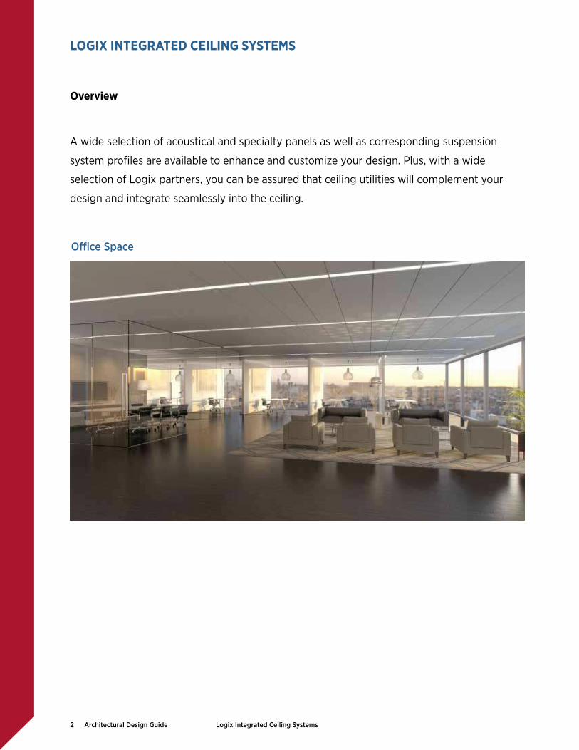
A wide selection of acoustical and specialty panels as well as corresponding suspension
system proiles are available to enhance and customize your design. Plus, with a wide
selection of Logix partners, you can be assured that ceiling utilities will complement your
design and integrate seamlessly into the ceiling.
LOGIX INTEGRATED CEILING SYSTEMS
Oice Space
Overview
3 Architectural Design Guide Logix Integrated Ceiling Systems
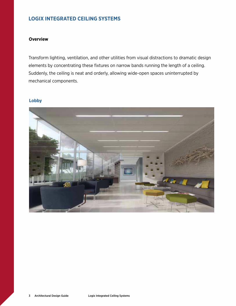
Transform lighting, ventilation, and other utilities from visual distractions to dramatic design
elements by concentrating these ixtures on narrow bands running the length of a ceiling.
Suddenly, the ceiling is neat and orderly, allowing wide-open spaces uninterrupted by
mechanical components.
LOGIX INTEGRATED CEILING SYSTEMS
Lobby
Overview

4 Architectural Design Guide Logix Integrated Ceiling Systems
Accentuate vertical elements and create a custom look without the custom cost while
using standard products, panels, and components. Positioning channels between main
tees allows you to enliven your design with continuous, uninterrupted, decorative, and
functional channels.
Airport
LOGIX INTEGRATED CEILING SYSTEMS
Overview

5 Architectural Design Guide Logix Integrated Ceiling Systems
Relected Ceiling Plan
Example Relected Ceiling
Plan (RCP) Layout1 1 1
2 4 42
6
27 7
2
2
3
5
5
5
8
5
1 Utility Channel
Inill Panel4
Opening for Luminaire,
Mechanical Grille, or Other Utility
2
Channel Panel3
Connector Panel
Yoke
Accessible Stabilizer Bar1
Channel-to-Channel
Module Unit
¹ Stabilizer bar required if opening ≥ 609. For more information about stabilizer bars, please refer to Plank and Large Panel Stabilizer Bars — Application Guide, IC592.
LOGIX INTEGRATED CEILING SYSTEMS

6 Architectural Design Guide Logix Integrated Ceiling Systems
Deinitions
Module The module is the measurement basis for coordinating the dimensions of the various
suspended ceiling materials and layouts to be designed and constructed.
There are two key module measurements in a Logix ceiling system:
Channel Module The measurement from the centerline of two adjacent utility
channels, also referred to as channel-to-channel spacing
Ceiling Module The measurement from the centerline of the suspension system
tees installed perpendicular to the utility channels
Module MeasurementsChannel Module
Cei
ling
Mod
ule
Util
ity c
hann
el
Util
ity c
hann
el
LOGIX INTEGRATED CEILING SYSTEMS
7 Architectural Design Guide Logix Integrated Ceiling Systems
Deinitions
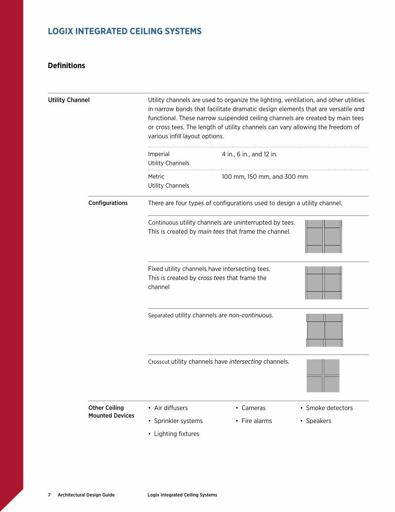
Utility Channel Utility channels are used to organize the lighting, ventilation, and other utilities
in narrow bands that facilitate dramatic design elements that are versatile and
functional. These narrow suspended ceiling channels are created by main tees
or cross tees. The length of utility channels can vary allowing the freedom of
various inill layout options.
Imperial
Utility Channels
4 in., 6 in., and 12 in.
Metric
Utility Channels
100 mm, 150 mm, and 300 mm
Conigurations There are four types of conigurations used to design a utility channel.
Continuous utility channels are uninterrupted by tees.
This is created by main tees that frame the channel.
Fixed utility channels have intersecting tees.
This is created by cross tees that frame the
channel
Separated utility channels are non-continuous.
Crosscut utility channels have intersecting channels.
Other Ceiling
Mounted Devices• Air difusers
• Sprinkler systems
• Lighting ixtures
• Cameras
• Fire alarms
• Smoke detectors
• Speakers
LOGIX INTEGRATED CEILING SYSTEMS

8 Architectural Design Guide Logix Integrated Ceiling Systems
Panels A variety of panel options are available to design a Logix ceiling system.
There are three types of panels.
Channel Panel Channel panels are narrow acoustical or metal ceiling panels used in utility
channels. Channel panels can be installed in a continuous manner creating
a monolithic and uninterrupted aesthetic or in conjunction with lighting,
ventilation and other utilities.
Inill Panel Inill panels are larger acoustical or metal ceiling panels installed in the space
between utility channels.
Connector Panel Connector panels are a unique option for USG Logix ceiling systems. Connector
panels visually connect various utilities in a utility channel such as luminaires
and channel panels. Connector panels are conigured to carry the adjacent
panel or ixture. No special ixture types or tile edges are needed. Connector
panels are metal and available in perforated and smooth inishes. Imperial and
metric sizes are available.
Deinitions
LOGIX INTEGRATED CEILING SYSTEMS

9 Architectural Design Guide Logix Integrated Ceiling Systems
Module Unit A module unit is a representative section of the ceiling system consisting of
two utility channels and the adjoining inill panels. Module units can be used
to estimate the materials needed to install a ceiling assembly. There are two
types of module units.
Of-Module Unit Of-Module units represent assemblies where typical ceiling panel sizes are
utilized between the utility channels. With the addition of the utility channel,
this creates of-module or nonstandard channel module (channel-to-channel)
spacing.
529 Channel Module
On-Module Unit On-Module units represent assemblies where atypical ceiling panel sizes are
utilized between the utility channels. With the addition of the utility channel, this
creates on-module or a standard channel module (channel-to-channel) spacing.
489 Channel Module
24" 24"4" channel panel 4" channel panel
4in
. ch
anne
l
4in
. ch
anne
l
52" Channel Module
Typical Inill Panel Size
22" 22"4" channel panel 4" channel panel
4in
. ch
anne
l
4in
. ch
anne
l
48" Channel Module
Atypical Inill Panel Size
For further module unit options, see page 20.
Deinitions
LOGIX INTEGRATED CEILING SYSTEMS

10 Architectural Design Guide Logix Integrated Ceiling Systems
Suspension Systems There are three types of grid suspension systems used in a Logix system.
Donn® DX®/DXL™
Standard
Centricitee™ DXT™
Narrow
Identitee™ DXI™
Double Reveal
Main Tee
Utility ChannelA utility channel created with main tees that frame that channel. This type of
channel is used in a continuous utility channel coniguration.
Cross Tee
Utility ChannelA utility channel created with cross tees that frame the channel. This type of
channel is used in a ixed, separated, or crosscut utility channel coniguration.
See layout details on page 19.
Cross Tee
Main Tee
Main Tee
Utility Channel
Cross Tee
Main Tee
Cross Tee
Utility Channel
Main Tee
Main Tee
Cross Tee
Cross Tee
Deinitions
LOGIX INTEGRATED CEILING SYSTEMS

11 Architectural Design Guide Logix Integrated Ceiling Systems
Yoke The USG Logix Yoke is an optional suspension system installation accessory
that facilitates the spacing and suspension of parallel main tees with one
hanger wire. The Logix yoke is compatible with both metric and imperial
utility channel sizes. The yoke also keeps hanger wire wraps away from linear
luminaires and can reduce the number of hanger wires required. The yoke
also helps to brace the utility channel.
Accessible Stabilizer Bar The USG Accessible Stabilizer Bar is a suspension system installation accessory
used in plank and large panel suspension systems. Specially notched safety
bars attach to the main tees and cross tees, which prevents the tee ends from
spreading and enhances the rigidity of large ceiling modules.
USG stabilizer bars are available in diferent sizes and options for various
applications. If the panel length is ≥ 60 in., then one stabilizer is required at
midpoint. If the panel length is ≥ 96 in., then two stabilizer bars are required
at the 1/3 and 2/3 points. These safety bars enhance system performance and
safety without limiting accessibility.
See layout details and assemblies on pages 17-18.
Deinitions
LOGIX INTEGRATED CEILING SYSTEMS

12 Architectural Design Guide Logix Integrated Ceiling Systems
1 Utility Channel Coniguration Continuous Fixed Separated Crosscut
5 Inill Panel Speciication Mars™ Mars™ High-NRC Halcyon™ Panz® Metal True™ Wood
6 Inill Panel Edge Proile Square FL SL FLB SLT
7 Grid Proile DXI Identitee DXT Centricitee Donn DX
8 Channel Panel Speciication Mars Mars High-NRC Halcyon Panz Metal
9 Channel Panel Edge Proile Square FL SL FLB SLT
2 Utility Channel Width Imperial Metric Custom
49, 69, 129 100 mm, 150 mm, 300 mm Contact your Sales
Representative
for custom options.3Channel Module Spacing
(Channel-to-Channel)48 58 68 78 88- 69
48- 49 58- 49 68- 69 78- 69 108- 69
48- 69 58- 69 128
1200 mm 1500 mm
1300 mm 1900 mm
1350 mm 1950 mm
4 Ceiling Module Dimension 48, 58, 68 ceiling module 1.25 m, 1.5 m, 1.75 m ceiling module
Selector Options
PLAN YOUR SYSTEM
13 Architectural Design Guide Logix Integrated Ceiling Systems
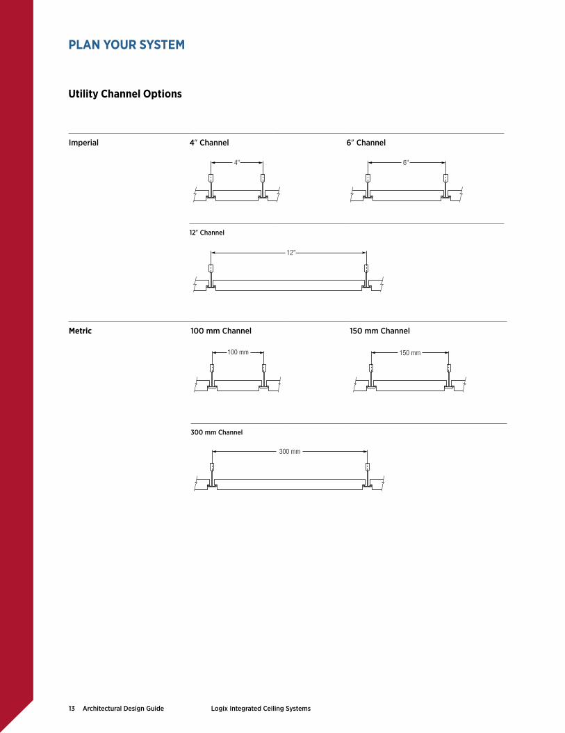
Imperial 49 Channel 69 Channel
4" 6"
129 Channel
12"
Metric 100 mm Channel 150 mm Channel
100 mm 150 mm
300 mm Channel
300 mm
Utility Channel Options
PLAN YOUR SYSTEM

14 Architectural Design Guide Logix Integrated Ceiling Systems
Inill Panel Options Halcyon™ Fiberglass Mars™ X-Technology Mineral Fiber
Mars™ High-NRC X-Technology Mineral Fiber
Panz® Unperforated Metal Aluminum
Panz® Wood ToneMetal
True™ WoodNatural Wood Veneers
Channel Panel Options Halcyon™ Fiberglass Mars™ X-Technology Mineral Fiber
Mars™ High-NRC X-Technology Mineral Fiber
Panz® Unperforated Metal Aluminum
Panz® Perforated, C116 Aluminum
Panz® Perforated, C116D Aluminum
Panz® Wood ToneMetal
The panel options listed below correspond to our standard ixed ceiling modules.
However, virtually all standard ceiling panels are possible with a continuous utility
channel system. Contact your sales representative for more information.
Panel Options
PLAN YOUR SYSTEM

15 Architectural Design Guide Logix Integrated Ceiling Systems
Maximum 28x 28 SQ Edge panels with DXT.
Panel Edge Options
FL FLB SL SLT SQ
Suspension Systems
Centricitee™ DXT™
PanZ® Metal
True™ Wood
Identitee™ DXI™
Panz Metal
Donn® DX®/DXL™
True™ Wood
Suspension System Options
PLAN YOUR SYSTEM

16 Architectural Design Guide Logix Integrated Ceiling Systems
The Logix connector panel is a unique way to visually connect various
utilities such as luminaires and channel panels. The connector panels are
conigured to carry the adjacent panel or ixture. No special ixture types
or tile edges are needed.
Options Finish Smooth, Unperforated Perforated, C116 Perforated, C116D
C116D
Color Flat White Painted
Edge Proile Reveal Edge Flush Mount
49 Channel 69 Channel
Imperial 49 x 129 49 x 249 69 x 129 69 x 249
100 mm Channel 150 mm Channel
Metric 100 mm x 300 mm 100 mm x 600 mm 1500 mm x 300mm 1500 mm x 600 mm
Connector Panels
PLAN YOUR SYSTEM

17 Architectural Design Guide Logix Integrated Ceiling Systems
YokeImperial
49 Channel 69 Channel 129 Channel
8 1/8"
fastener
placement
(2 required)
4 25/32"
8 1/8"
fastener
placement
(2 required)
6 25/32" 12 25/32"
fastener placement(4 required)
cut main tee to be used as a bridge to lengthen yoke
8 1/8"
hanger wires (2 required)
YokeMetric
100 mm Channel 150 mm Channel 300 mm Channel
120.40 mm
fastener
placement
(2 required)
206.38 mm
170.18 mm
206.38 mm
fastener
placement
(2 required)
206.38 mm
fastener placement(4 required)
cut main tee to be used as a bridge to lengthen yoke
hanger wires (2 required)
320.18 mm
The Logix yoke is compatible with both metric and imperial utility channel sizes. The yoke keeps hanger wire wraps
away from linear luminaires and may reduce the number of hanger wires required. The yoke also helps to brace the
utility channel. The yoke is easy to install and is seismic tested.
Note: The USG yoke provides connections that exceed the 180 lb. requirement for Seismic Design Categories D-F.
Logix Yoke
PLAN YOUR SYSTEM

18 Architectural Design Guide Logix Integrated Ceiling Systems
Yoke with Connector Panel The Logix yoke is compatible with all utility channel options and applications.
The connector panel shown is one of many options allowing the freedom to
transform the utilities into dramatic design elements.
The connector panel is secured to the adjacent main tees by folding tabs; the folding tabs should be folded inwards to insure ceiling section alignment.
hanger wire
cross tee
main tee
4" or 6" connector
panel
4" or 6" adjustable yoke
secure tab with 1/8" pop-rivet
Yoke with Recessed Linear Luminaires
Logix is compatible with a wide selection of 49, 69, and 129 luminaires including
Lumination™ LED Luminaires by GE Lighting Solutions. For more information
visit: www.gelightingsolutions.com.
hanger wire
cross tee
main tee
lighting fixture
4" or 6" adjustable yoke
Yoke Assemblies
PLAN YOUR SYSTEM

19 Architectural Design Guide Logix Integrated Ceiling Systems
Utility Channel Created with Main Tees
Utility Channel Created with Cross Tees
lighting fixture
hanger wire
main tee
cross tees
If opening is ≥ 60",
then one stabilizer bar
is required at midpoint.
If opening is ≥ 96",
then two stabilizer bars are
required at 1/3 and 2/3 points.
utility panel
cross tee
nom. 4" to 12"
channel width
accommodates
continuous fixtures
variable
channel width
yoke
connector
panel
main tees
variable length fixtures
lighting fixturefield panel
main tee
hanger wire
If opening is ≥ 60",
then one stabilizer bar is
required at midpoint.
If opening is ≥ 96",
then two stabilizer bars are
required at 1/3 and 2/3 points.
yoke or two
vertical hanger wires
Layout Options
DESIGN CONSIDERATIONS

20 Architectural Design Guide Logix Integrated Ceiling Systems
22"4" 4"22"
48" Channel Module
Ceili
ng M
odule
Utilit
y C
hannel
Utilit
y C
hannel
24"4" 4"24"
52" Channel Module Off-Module On-Module
48" (4'-0")
60" (5'-0")
72" (6'-0")
144" (12'-0")
52" (4'-4")
54" (4'-6")
64" (5'-4")
66" (5'-6")
78" (6'-6")
90" (7'-6")
100" (8'-4")
102" (8'-6")
126" (10'-6")
Ceili
ng M
odule
Utilit
y C
hannel
Utilit
y C
hannel
Module Unit Module Unit
Of-Module Units
Of-Module units represent assemblies where typical ceiling
panel sizes are utilized between the utility channels. With
the addition of the utility channel, this creates of-module or
nonstandard channel-to-channel spacing.
On-Module Units
On-Module units represent assemblies where atypical ceiling
panel sizes are utilized between the utility channels. With
the addition of the utility channel, this creates on-module or
standard channel-to-channel spacing.
Ceiling Modules
DESIGN CONSIDERATIONS

21 Architectural Design Guide Logix Integrated Ceiling Systems
Other ceiling mounted devices not shown
such as:
• Cameras
• Fire Alarms
• Smoke Detectors
• Speakers, etc.
sprinkler
fixture attachment
4", 6" or 12"
4", 6" or 12"
4", 6" or 12"
Air Diffuser
Utility Applications
Sprinkler System
Lighting Fixture
Channel Panel Options • Perforated Metal
• Unperforated Metal
• Halcyon™
• Mars™
• Mars™ High-NRC
Utility Channel Example Layouts
Numerous mechanical conigurations in the utility channel are possible. Coordination of light ixtures, mechanical
grilles, channel panels, and inill panels can vary based on function, code requirements, and architectural design
intent. Contact your sales representative for more information.
Utility Channel Options
DESIGN CONSIDERATIONS

22 Architectural Design Guide Logix Integrated Ceiling Systems
Virtually all suspended ceiling systems are possible with a continuous utility channel system. Nearly all suspended
ceiling systems can be installed between continuous utility channels. Contact your sales representative for more
information.
Standard 28 x 28 Ceiling Layout Standard 28 x 48 Ceiling Layout
continuous
utility channel
standard 2'x 2'
suspended ceiling
continuous
utility channel
standard 2'x4'
suspended ceiling
Standard 309 x 309 Ceiling Layout Standard 48 x 48 Ceiling Layout
continuous
utility channel
standard 30"x 30"
suspended ceiling
continuous
utility channel
standard 4'x 4'
suspended ceiling
DESIGN CONSIDERATIONS
Continuous Utility Channels

23 Architectural Design Guide Logix Integrated Ceiling Systems
DESIGN CONSIDERATIONS
Drywall Ceilings
The USG drywall suspension system is a pre-engineered drywall ceiling system speciically created to simplify
the design and construction of drywall ceilings. The system allows you to create unique and conventional drywall
ceilings. The system assembles quickly and easily for faster installation and allows for the easy transition to
acoustical ceilings, and vertical, horizontal, and curved surfaces. The USG drywall suspension system components
come with a 10-year warranty and the system has a lifetime limited warranty when used with USG Sheetrock® Brand
gypsum panels.
Integrating linear luminaires with the USG drywall suspension system creates a ceiling with advanced engineering,
crisp lines and a strikingly pure aesthetic.
Example Layouts
wall channel
6’ cross tee
main tee
fasteners 6" to 8" o.c.
hanger wire
48" o.c.adjustable yoke
SHEETROCK
gypsum panels
54" wide SHEETROCK
gypsum panels

24 Architectural Design Guide Logix Integrated Ceiling Systems
DESIGN CONSIDERATIONS
Drywall Ceilings
Example Layouts
Example Luminaire Applications
Trim Flange Luminaire Trimless Luminaire
lighting support bracket
drywall suspension tee
screw attached
through drywall
into grid
lighting unit
trim flange
lighting unit
flush light cover
drywall suspension tee
screw attached
through drywall
into grid
tape and
mud finishedflush light cover
lighting unit
wall angle
6' cross tee
main tee
fasteners 6" to 8" o.c.
hanger wire
48" o.c.
lighting
fixture
SHEETROCK
gypsum panels

25 Architectural Design Guide Logix Integrated Ceiling Systems
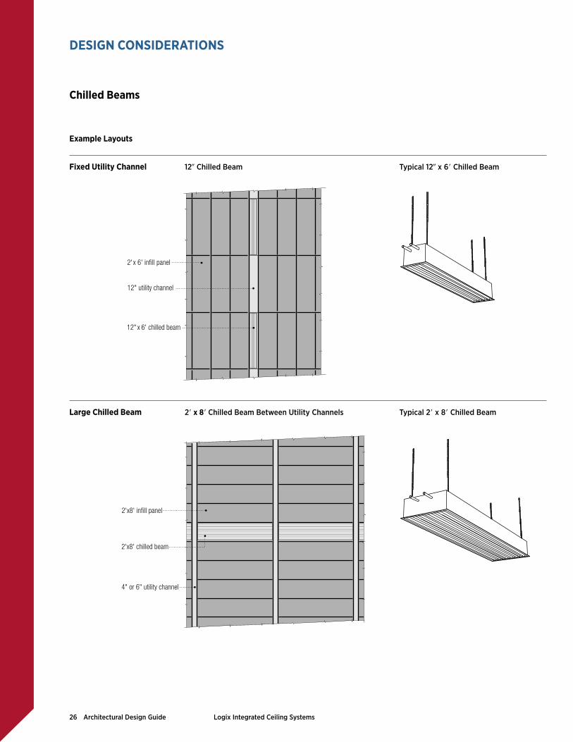
Chilled beams are part of a convection HVAC system where pipes of water are fed through a heat exchanger called
a chilled beam for the purpose of controlling the climate of the space below. Chilled beams can be either active or passive. Active beams provide ventilation air in addition to cooling, while passive beams consist of a cooling
coil in an enclosure. Multi-service chilled beams can integrate a variety of other services including speakers,
lighting, sprinkler heads, etc. Chilled beams can either be exposed below the suspended ceiling or integrated into
the suspended ceiling. Logix is designed to accommodate 12 in. chilled beam ixtures and integrate them into the
12 in. Logix utility channel. Larger chilled beams may be incorporated between utility channels.
Example Layouts
Continuous Utility Channels 129 Chilled Beam Typical 129 x 68 Chilled Beam
129 Chilled Beam Typical 129 x 68 Chilled Beam
DESIGN CONSIDERATIONS
Chilled Beams
12"x 6' chilled beam
30"x 60" infill panel
12" utility channel
12"x 6' chilled beam
2'x 6' infill panel
12" utility channel
26 Architectural Design Guide Logix Integrated Ceiling Systems
Example Layouts
Fixed Utility Channel 129 Chilled Beam Typical 129 x 68 Chilled Beam
Large Chilled Beam 28 x 88 Chilled Beam Between Utility Channels Typical 28 x 88 Chilled Beam
DESIGN CONSIDERATIONS
Chilled Beams
12" x 6' chilled beam
2'x 6' infill panel
12" utility channel
2'x8' infill panel
2'x8' chilled beam
4" or 6" utility channel

27 Architectural Design Guide Logix Integrated Ceiling Systems
LogiX Partners Logix is compatible with a wide selection of 4 in., 6 in., and 12 in. luminaires and
utilities, as well as 100 mm, 150 mm, and 300 mm luminaires and utilities. lumi-
naires and utilities. USG has dedicated a permanent space to test and evaluate
compatible products and prequalify them for it and inish. For more informa-
tion about the dimensions of Logix components and assemblies, please refer to
IC609 Logix Critical System Dimensions.
Lighting • Amerlux
• A Light
• Focal Point
• GE Lighting
• Zumtobel
Difuser • Carnes
Sprinkler • SprinkFlex
DESIGN CONSIDERATIONS
Logix Partners

PRODUCT INFORMATION
See usg.com for the most up-to-date product information.
INSTALLATION
Must be installed in compliance with ASTM C636, ASTM E580, CISCA and standard industry practices, within all applicable code requirements. Alternative assemblies and installation methods may be utilized when approved by the Authority Having Jurisdiction. USG recommends checking with the Authority Having Jurisdiction prior to designing and installing a suspended ceiling system.
CODE COMPLIANCE
The information presented is correct to the best of our knowledge at the date of issuance. Because codes continue to evolve, check with a local oicial prior to designing and install-
ing a ceiling system. Other restrictions and
exemptions may apply. This is only intended
as a quick installation reference.
ICC EVALUATION SERVICE, INC.,
REPORT COMPLIANCE
Suspension systems manufactured by USG
Interiors, Inc., have been reviewed and are
approved by listing in ICC-Evaluation Service
Report ESR-1222. Evaluation Reports are sub-
ject to reexamination, revision and possible
cancellation. Please refer to usgdesignstudio.
com or usg.com for current reports.
L.A. RESEARCH REPORT Compliance
Donn brand suspension systems manufactured
by USG Interiors, Inc., have been reviewed and
are approved by listing in the following
L.A. Research Report number: 25764.
NOTICE
We shall not be liable for incidental and
consequential damages, directly or indirectly
sustained, nor for any loss caused by applica-
tion of these goods not in accordance with
current printed instructions or for other than
the intended use. Our liability is expressly
limited to replacement of defective goods.
Any claim shall be deemed waived unless
made in writing to us within thirty (30) days
from date it was or reasonably should have
been discovered.
SAFETY FIRST!
Follow good safety/industrial hygiene
practices during installation. Wear appropriate
personal protective equipment. Read MSDS
and literature before speciication and
installation.
IS287/10-14
© 2014, USG Corporation or its ailiates. All rights reserved.
The trademarks CENTRICITEE, DX, DXL, DONN, DXI, FINELINE, HALCYON, IDENTITEE, LOGIX, MARS, USG, IT’S YOUR
WORLD BUILD IT, THE USG LOGO and related marks are trademarks of USG Interiors, LLC or a related company.
GE Lighting Solutions, LLC is a subsidiary of the General Electric Company. The GE brand logo, Lumination are trademarks
of the General Electric Company. © 2012 GE Lighting Solutions, LLC.
WEBSITES
usg.com
seismicceilings.com
sustainableceilings.com
usgdesignstudio.com
TECHNICAL SERVICE
800 USG.4YOU (800 874.4968)
CUSTOMER SERVICE
800 950.3839
Recommended