00-02-0671 2016-04-14 Section 15
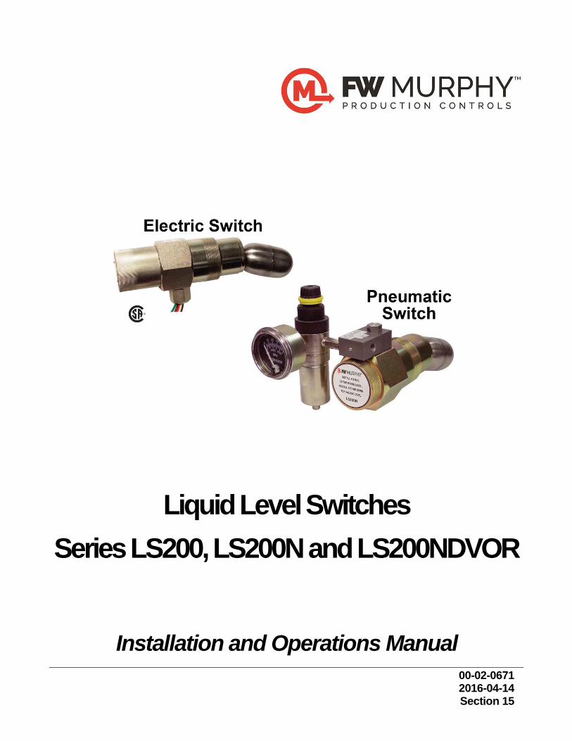
Liquid Level Switches
Series LS200, LS200N and LS200NDVOR
Installation and Operations Manual
CAUTION: LS200 Series parts are not interchangeable with other
FW Murphy liquid level products. Damage caused by using incorrect
parts is not covered by our Limited Warranty.
Please read the following information before installing. A visual inspection for damage during shipping is recommended before mounting.
BEFORE BEGINNING INSTALLATION OF THIS FW MURPHY PRODUCT:
Disconnect all electrical power to the machine.
Make sure the machine cannot operate during installation.
Follow all safety warnings of the machine manufacturer.
Read and follow all installation instructions.
OBSERVE all pressure and electrical ratings and requirements for the devices and the operating environment.
BE SURE all pressure HAS BEEN REMOVED from the vessel before opening any pressure connections.
Please contact FW Murphy immediately if you have any questions.
Table of Contents
Product Information ................................................................................................................... 1
Features .......................................................................................................................1
LS200 ...........................................................................................................................1
LS200NDVOR ..............................................................................................................2
LS200NDVO ................................................................................................................3
LS200N ........................................................................................................................3
Pressure Vessel Installation: LS200 and LS200N ................................................................ 4
Direct Installation into the Wall of the Pressure Vessel ................................................4
Installation with a Weld Collar ......................................................................................5
Installation Using FW Murphy External Float Chamber ................................................5
Installation and Adjustment for Pneumatic Models .......................................................6
Replacing and Installing the DVO Assembly ......................................................................... 7
Models LS200NDVO & LS200NDVOR ........................................................................7
Electrical ...................................................................................................................................... 9
Replacement Parts ..................................................................................................................... 9
Accessories .............................................................................................................................. 10
15050375: Weld Collar .............................................................................................. 10
55050617: DVU150/DVU175 Adapter Bushing ......................................................... 10
15051098: External Float Chamber .......................................................................... 11
15700799: Series 100 External Float Chamber ........................................................ 11
15000478: Float Shaft Extension for the LS200 ........................................................ 11
The FW Murphy Gas Compressor Scrubber Level System (SLS) ............................. 12
Specifications ........................................................................................................................... 13
All Models ................................................................................................................... 13
LS200 ......................................................................................................................... 13
LS200NDVOR ............................................................................................................ 13
LS200NDVO .............................................................................................................. 13
LS200 N ..................................................................................................................... 13
Approximate Shipping Weights and Dimensions ........................................................ 13

THIS PAGE INTENTIONALLY LEFT BLANK
Section 15 00-02-0671 2016-04-14 - 1 -
Product Information
Features
Listed for Class I, Div. 1, Grp. C & D locations
Canadian Registration Number OF1476.2
Minimum Allowable Specific Gravity for LS200
Table 1 LS200 Minimum Allowable Specific Gravity
Model Float Extension length
Pressure Specific Gravity
(inch) (psi)
0 0.55
LS200 1 2000 0.7
6 1
0 0.63
LS200NDVO 1 2000 0.73
6 1.02
*Note: The min. allowable SG will decrease with a decrease in operating pressure
LS200
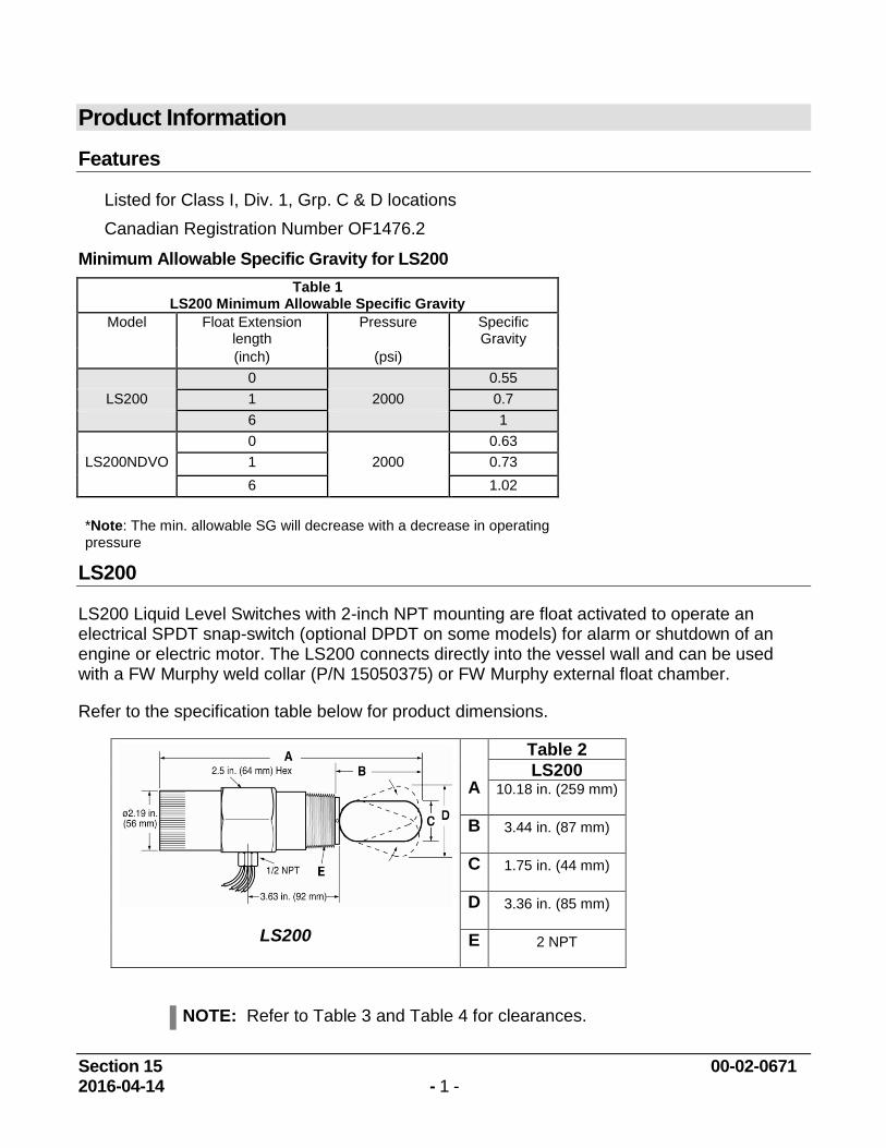
LS200 Liquid Level Switches with 2-inch NPT mounting are float activated to operate an electrical SPDT snap-switch (optional DPDT on some models) for alarm or shutdown of an engine or electric motor. The LS200 connects directly into the vessel wall and can be used with a FW Murphy weld collar (P/N 15050375) or FW Murphy external float chamber.
Refer to the specification table below for product dimensions.
LS200
A
Table 2
LS200 10.18 in. (259 mm)
B 3.44 in. (87 mm)
C 1.75 in. (44 mm)
D 3.36 in. (85 mm)
E 2 NPT
NOTE: Refer to Table 3 and Table 4 for clearances.
Section 15 00-02-0671 2016-04-14 - 2 -
LS200NDVOR
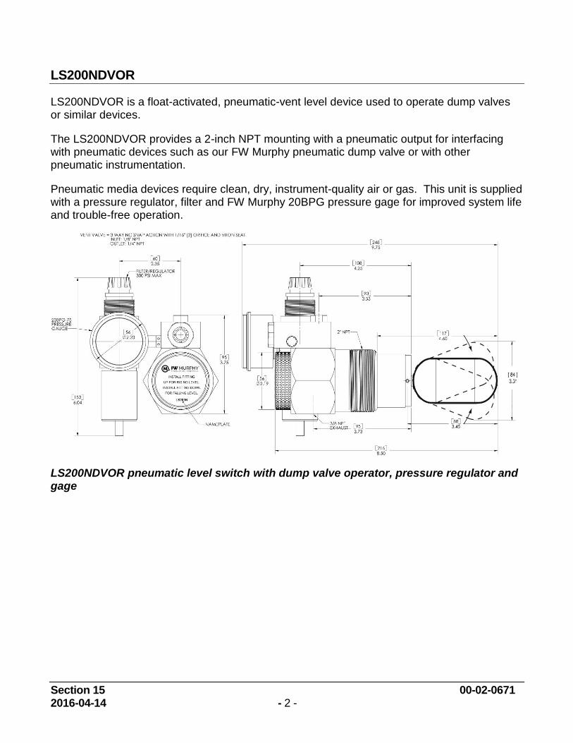
LS200NDVOR is a float-activated, pneumatic-vent level device used to operate dump valves or similar devices.
The LS200NDVOR provides a 2-inch NPT mounting with a pneumatic output for interfacing with pneumatic devices such as our FW Murphy pneumatic dump valve or with other pneumatic instrumentation.
Pneumatic media devices require clean, dry, instrument-quality air or gas. This unit is supplied with a pressure regulator, filter and FW Murphy 20BPG pressure gage for improved system life and trouble-free operation.
LS200NDVOR pneumatic level switch with dump valve operator, pressure regulator and gage
Section 15 00-02-0671 2016-04-14 - 3 -
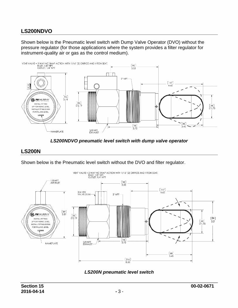
LS200NDVO
Shown below is the Pneumatic level switch with Dump Valve Operator (DVO) without the pressure regulator (for those applications where the system provides a filter regulator for instrument-quality air or gas as the control medium).
LS200NDVO pneumatic level switch with dump valve operator
LS200N
Shown below is the Pneumatic level switch without the DVO and filter regulator.
LS200N pneumatic level switch
Section 15 00-02-0671 2016-04-14 - 4 -
Pressure Vessel Installation: LS200 and LS200N
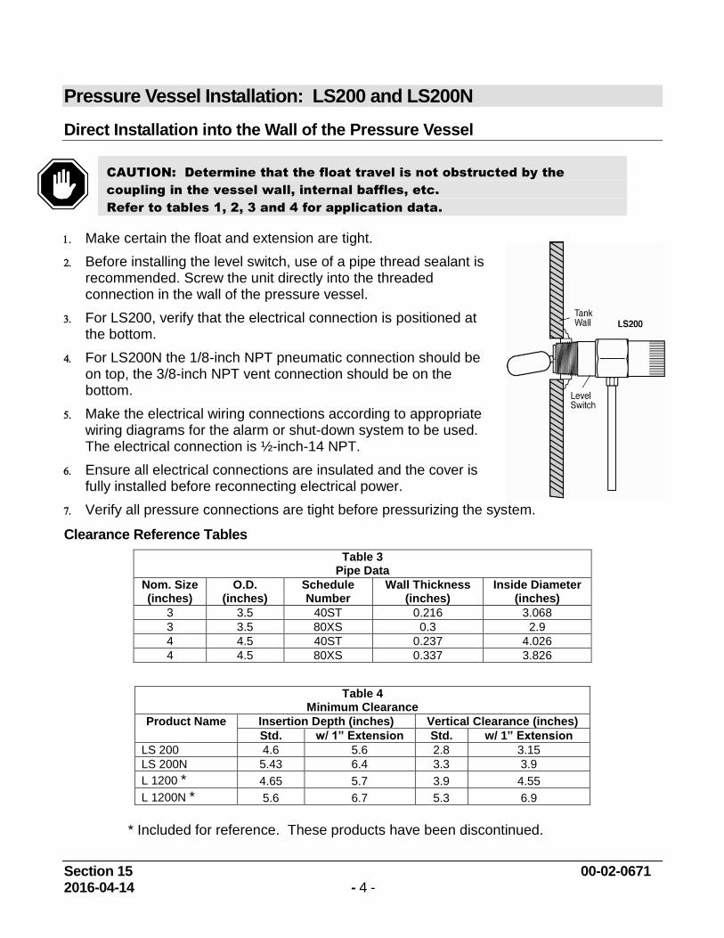
Direct Installation into the Wall of the Pressure Vessel
CAUTION: Determine that the float travel is not obstructed by the
coupling in the vessel wall, internal baffles, etc.
Refer to tables 1, 2, 3 and 4 for application data.
Make certain the float and extension are tight.
Before installing the level switch, use of a pipe thread sealant is recommended. Screw the unit directly into the threaded connection in the wall of the pressure vessel.
For LS200, verify that the electrical connection is positioned at the bottom.
For LS200N the 1/8-inch NPT pneumatic connection should be on top, the 3/8-inch NPT vent connection should be on the bottom.
Make the electrical wiring connections according to appropriate wiring diagrams for the alarm or shut-down system to be used. The electrical connection is ½-inch-14 NPT.
Ensure all electrical connections are insulated and the cover is fully installed before reconnecting electrical power.
Verify all pressure connections are tight before pressurizing the system.
Clearance Reference Tables
Table 3 Pipe Data
Nom. Size (inches)
O.D. (inches)
Schedule Number
Wall Thickness (inches)
Inside Diameter (inches)
3 3.5 40ST 0.216 3.068
3 3.5 80XS 0.3 2.9
4 4.5 40ST 0.237 4.026
4 4.5 80XS 0.337 3.826
Table 4 Minimum Clearance
Product Name Insertion Depth (inches) Vertical Clearance (inches)
Std. w/ 1” Extension Std. w/ 1” Extension
LS 200 4.6 5.6 2.8 3.15
LS 200N 5.43 6.4 3.3 3.9
L 1200 * 4.65 5.7 3.9 4.55
L 1200N * 5.6 6.7 5.3 6.9
* Included for reference. These products have been discontinued.
Section 15 00-02-0671 2016-04-14 - 5 -
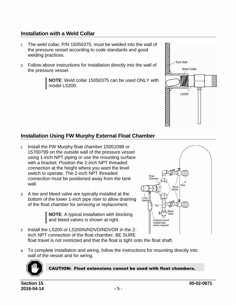
Installation with a Weld Collar
The weld collar, P/N 15050375, must be welded into the wall of the pressure vessel according to code standards and good welding practices.
Follow above instructions for installation directly into the wall of the pressure vessel.
NOTE: Weld collar 15050375 can be used ONLY with model LS200.
Installation Using FW Murphy External Float Chamber
Install the FW Murphy float chamber 15051098 or 15700799 on the outside wall of the pressure vessel using 1-inch NPT piping or use the mounting surface with a bracket. Position the 2-inch NPT threaded connection at the height where you want the level switch to operate. The 2-inch NPT threaded connection must be positioned away from the tank wall.
A tee and bleed valve are typically installed at the bottom of the lower 1-inch pipe riser to allow draining of the float chamber for servicing or replacement.
NOTE: A typical installation with blocking and bleed valves is shown at right.
Install the LS200 or LS200N/NDVO/NDVOR in the 2-inch NPT connection of the float chamber. BE SURE float travel is not restricted and that the float is tight onto the float shaft.
To complete installation and wiring, follow the instructions for mounting directly into wall of the vessel and for wiring.
CAUTION: Float extensions cannot be used with float chambers.
Section 15 00-02-0671 2016-04-14 - 6 -
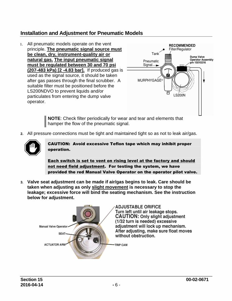
Installation and Adjustment for Pneumatic Models
All pneumatic models operate on the vent principle. The pneumatic signal source must be clean, dry, instrument-quality air or natural gas. The input pneumatic signal must be regulated between 30 and 70 psi (207-483 kPa) [2 -4.83 bar]. If produced gas is used as the signal source, it should be taken after gas passes through the final scrubber. A suitable filter must be positioned before the LS200NDVO to prevent liquids and/or particulates from entering the dump valve operator.
NOTE: Check filter periodically for wear and tear and elements that hamper the flow of the pneumatic signal.
2. All pressure connections must be tight and maintained tight so as not to leak air/gas.
CAUTION: Avoid excessive Teflon tape which may inhibit proper
operation.
Each switch is set to vent on rising level at the factory and should
not need field adjustment. For testing the system, we have
provided the red Manual Valve Operator on the operator pilot valve.
3. Valve seat adjustment can be made if air/gas begins to leak. Care should be taken when adjusting as only slight movement is necessary to stop the leakage; excessive force will bind the seating mechanism. See the instruction below for adjustment.
Section 15 00-02-0671 2016-04-14 - 7 -
Replacing and Installing the DVO Assembly
NOTE: When replacing/installing the DVO assembly, tubing and fitting modifications may be required. We suggest removing the LS200NDVO/DVOR from the vessel. Relieve pressure from the vessel or use block valves before removing the LS200NDVO/DVOR.
Models LS200NDVO & LS200NDVOR
NOTE: Clean, dry, instrument-quality gas should be used. Use and regular maintenance of filters will improve service life and reliability.
Tools Needed
2-1/2 inch hex wrench or pipe wrench with smooth jaws
9/16-inch hex wrench
Tubing cutters and benders
Instructions
Block off and bleed the instrument gas pressure supply to the LS200NDVO/DVOR.
Remove the tubing between the LS200NDVO/DVOR and the scrubber dump valve, and remove the supply gas tubing (regulator [-R-] if used).
Remove the LS200NDVO/DVOR from the vessel (optional).
If the LS200NDVO/DVOR was removed from the vessel, mount it in a suitable vise on a work bench (if possible).
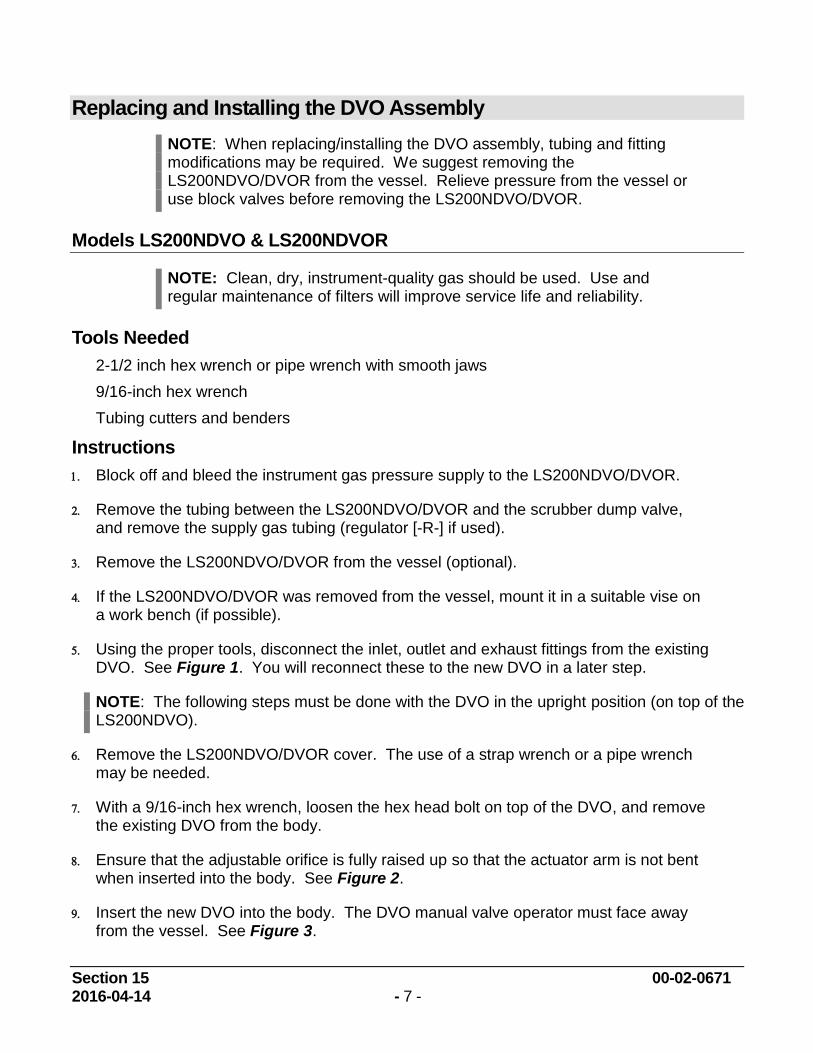
Using the proper tools, disconnect the inlet, outlet and exhaust fittings from the existing DVO. See Figure 1. You will reconnect these to the new DVO in a later step.
NOTE: The following steps must be done with the DVO in the upright position (on top of the LS200NDVO).
Remove the LS200NDVO/DVOR cover. The use of a strap wrench or a pipe wrench may be needed.
With a 9/16-inch hex wrench, loosen the hex head bolt on top of the DVO, and remove the existing DVO from the body.
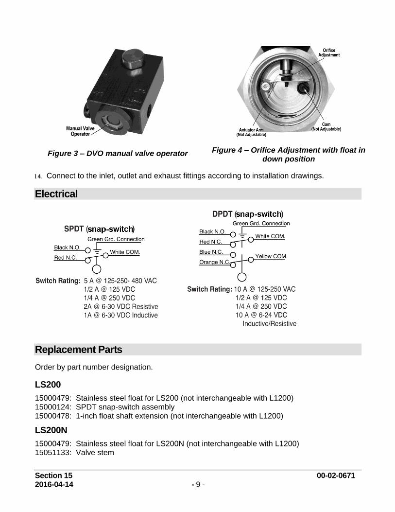
Ensure that the adjustable orifice is fully raised up so that the actuator arm is not bent when inserted into the body. See Figure 2.
Insert the new DVO into the body. The DVO manual valve operator must face away from the vessel. See Figure 3.
Section 15 00-02-0671 2016-04-14 - 8 -
Figure 1 - DVO
Figure 2 – Adjustable Orifice
CAUTION: Ensure that the actuator arm is not bent during
reassembly
With the DVO aligned over the hex on the LS200NDVO body, tighten the valve using the 9/16-inch hex wrench. You may need to hold the DVO while tightening to keep it from rotating.
The pneumatic input signal should be regulated between 30 and 70 psi for proper setting of the adjustable orifice. With the float in the down position, adjust the adjustable orifice down until it touches the seat. See Figure 4. If the DVO is still leaking, make slight adjustments (1/32 turn). Excessive adjustments will lock up mechanisms. After adjusting, make sure float moves freely up and down.
Replace the LS200NDVO/DVOR cover.
Using the appropriate tools reinstall the inlet, outlet and exhaust fittings to the new DVO.
NOTE: Thread sealant is recommended although care should be used to not allow excess to enter valve.
Section 15 00-02-0671 2016-04-14 - 9 -
Connect to the inlet, outlet and exhaust fittings according to installation drawings.
Electrical
Replacement Parts
Order by part number designation.
LS200
15000479: Stainless steel float for LS200 (not interchangeable with L1200) 15000124: SPDT snap-switch assembly 15000478: 1-inch float shaft extension (not interchangeable with L1200)
LS200N
15000479: Stainless steel float for LS200N (not interchangeable with L1200) 15051133: Valve stem
Figure 3 – DVO manual valve operator
Figure 4 – Orifice Adjustment with float in down position
Section 15 00-02-0671 2016-04-14 - 10 -
LS200NDVO and LS200NDVOR
55050621: Regulator only 05704480: 20BPG-D-75 Square Port Pressure gage 0-75 psi (517 kPa) [5.17 bar] 15000237: Regulator Gauge Assembly (includes regulator, gauge and fittings) 15010267: Assembly (LS200N DVO Assembly)
Accessories
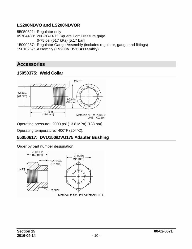
15050375: Weld Collar
Operating pressure: 2000 psi (13.8 MPa) [138 bar].
Operating temperature: 400F (204C).
55050617: DVU150/DVU175 Adapter Bushing
Order by part number designation
Section 15 00-02-0671 2016-04-14 - 11 -
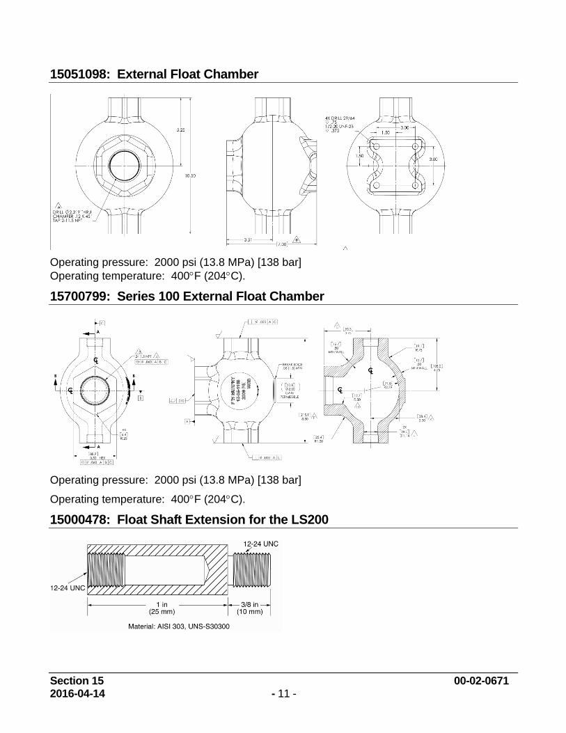
15051098: External Float Chamber
Operating pressure: 2000 psi (13.8 MPa) [138 bar]
Operating temperature: 400F (204C).
15700799: Series 100 External Float Chamber
Operating pressure: 2000 psi (13.8 MPa) [138 bar]
Operating temperature: 400F (204C).
15000478: Float Shaft Extension for the LS200
Section 15 00-02-0671 2016-04-14 - 12 -
CAUTION: Use of 1-inch extension requires additional clearance.
Refer to Tables 1, 2, 3 and 4 for application data.
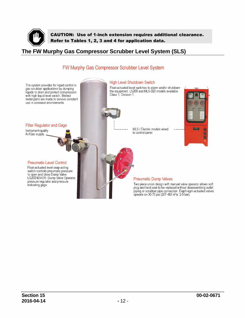
The FW Murphy Gas Compressor Scrubber Level System (SLS)
Section 15 00-02-0671 2016-04-14 - 13 -
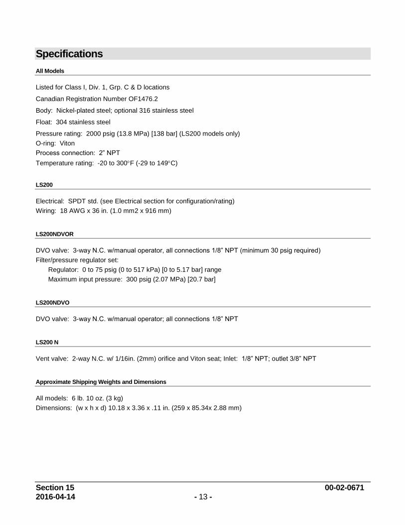
Specifications
All Models
Listed for Class I, Div. 1, Grp. C & D locations
Canadian Registration Number OF1476.2
Body: Nickel-plated steel; optional 316 stainless steel
Float: 304 stainless steel
Pressure rating: 2000 psig (13.8 MPa) [138 bar] (LS200 models only)
O-ring: Viton
Process connection: 2” NPT
Temperature rating: -20 to 300F (-29 to 149C)
LS200
Electrical: SPDT std. (see Electrical section for configuration/rating)
Wiring: 18 AWG x 36 in. (1.0 mm2 x 916 mm)
LS200NDVOR
DVO valve: 3-way N.C. w/manual operator, all connections 1/8” NPT (minimum 30 psig required)
Filter/pressure regulator set:
Regulator: 0 to 75 psig (0 to 517 kPa) [0 to 5.17 bar] range
Maximum input pressure: 300 psig (2.07 MPa) [20.7 bar]
LS200NDVO
DVO valve: 3-way N.C. w/manual operator; all connections 1/8” NPT
LS200 N
Vent valve: 2-way N.C. w/ 1/16in. (2mm) orifice and Viton seat; Inlet: 1/8” NPT; outlet 3/8” NPT
Approximate Shipping Weights and Dimensions
All models: 6 lb. 10 oz. (3 kg)
Dimensions: (w x h x d) 10.18 x 3.36 x .11 in. (259 x 85.34x 2.88 mm)

NOTES

NOTES
Recommended


![Compact Photoelectric Sensor [Amplifier Built-in] CX-400 ...Amplifier Built-in Power Supply Built-in Amplifier-separated C-400 CY-100 E-10 E-20 E-30 E-40 C-440 E-30 E-500 M-W R-LS200](https://img.pdfslide.us/doc/110x75/5f0279117e708231d4046f04/compact-photoelectric-sensor-amplifier-built-in-cx-400-amplifier-built-in.jpg)