Lighting Controllers and Accessories CatalogComplete energy-saving lighting control solutions
INTELLIGENT LIGHTING CONTROLS, INC.
www.ilc-usa.com
Made inthe USA
InSite
L I G H T I N G C O N T R O L S O F T W A R E
G U I U S E R I N T E R F A C E S E C U R I T Y A P P L I C A T I O N S
ILC features a complete line…
L I G H T I N G C O N T R O L L E R S
D A T A L I N E C O N T R O L D E V I C E S
…of lighting control solutions.

For over 25 years, Intelligent Lighting Controls (ILC) has been a leader in the lighting
control industry. We engineer and manufacture all of our products internally, allowing
us to maintain superior quality and ensure your highest satisfaction. At ILC, we’re
constantly improving our products to provide you with the most innovative, reliable
lighting control solutions available. From our superior relays to our sophisticated yet
easy-to-use controllers, we can proudly say that all of our products are completely
designed, built, tested, and shipped directly from our headquarters right here in the USA!
Since lighting control is all we do, we focus all our resources on providing you with:
• User-friendly lighting control systems that offer huge energy savings
• Products to help you achieve LEED certification
• State of the art controllers that allow for easy network expansion
• High quality relays for greater reliability
• Products tailored to meet your individual needs—completely factory wired, tested,
and documented
• Lighting controls that work seamlessly with existing as well as new construction
Our products are marketed through a network of over 80 independent lighting
manufacturers’ representatives throughout the nation who can assist you in deciding
exactly which ILC products are right for your needs. Contact us to find a rep in your
area. For more information about ILC’s products, visit www.ilc-usa.com or call us at
1-800-922-8004. We’ll be happy to personally answer any questions you have.
We’re confident you’ll discover that ILC has the most advanced and complete lighting
control solutions for your project—whether it’s a simple stand-alone remote panel, an
extensive campus-wide system, or anything else in between.
Thank you for choosing ILC!
1
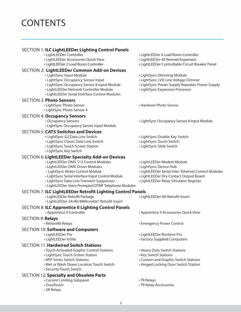
COnTEnTS
2
SECTIOn 1: ILC LightLEEDer Lighting Control Panels• LightLEEDer Controller • LightLEEDer 4 Load Room Controller• LightLEEDer Accessories Quick View • LightLEEDer-4X Remote/Expansion • LightLEEDer 2 Load Room Controller • LightLEEDer Controllable Circuit Breaker Panel
SECTIOn 2: LightLEEDer Common Add-on Devices • LightSync Input Module • LightSync Dimming Module• LightSync Occupancy Sensor Input • LightSync LVD Line Voltage Dimmer• LightSync Occupancy Sensor 8 Input Module • LightSync Power Supply Repeater, Power Supply• LightLEEDer network Controller Module • LightSync Expansion Processor• LightLEEDer Serial Interface Control Modules
SECTIOn 3: Photo Sensors• LightSync Photo Sensor • Hardwire Photo Sensor• LightSync Photo Sensor 4
SECTIOn 4: Occupancy Sensors • Occupancy Sensors • LightSync Occupancy Sensor 8 Input Module• LightSync Occupancy Sensor Input Module
SECTIOn 5: CAT5 Switches and Devices • LightSync G2 Data Line Switch • LightSync Disable Key Switch• LightSync Classic Data Line Switch • LightSync Touch Switch• LightSync Touch Screen Station • LightSync Slide Switch• LightSync Key Switch
SECTIOn 6: LightLEEDer Specialty Add-on Devices• LightLEEDer DMX 512 Control Modules • LightLEEDer Modem Module• LightLEEDer DMX Driver Modules • LightSync Device Hub • LightSync Motor Control Module • LightLEEDer Serial Inter. Ethernet Control Modules
• LightSync Serial Interface Input Control Module • LightLEEDer Dry Contact Output Board• LightSync Data Line Transient Suppressor • LightLEEDer Relay Simulator Register• LightLEEDer Voice Prompted DTMF Telephone Modules
SECTIOn 7: ILC LightLEEDer Retrofit Lighting Control Panels • LightLEEDer Retrofit Package • LightLEEDer-8X Retrofit Insert• LightLEEDer-24/40/48Microlite® Retrofit Insert
SECTIOn 8: ILC Apprentice II Lighting Control Panels• Apprentice II Controller • Apprentice II Accessories Quick View
SECTIOn 9: Relays• Reliant40 Relays • Emergency Power Control
SECTIOn 10: Software and Computers• LightLEEDer Pro • LightLEEDer Runtime Pro• LightLEEDer InSite • Factory Supplied Computers
SECTIOn 11: Hardwired Switch Stations• Touch Activated Graphic Control Stations • Heavy Duty Switch Stations• LightSync Touch Screen Station • Key Switch Stations• nFP Series Switch Stations • Custom and Graphic Switch Stations• Wet or Wash-Down Location Touch Switch • Hinged Locking Door Switch Station• Security Touch Switch
SECTIOn 12: Specialty and Obsolete Parts• Current Limiting Subpanel • TR Relays • DuraTouch • TR Relay Accessories• 2R Relays
Section 1: ILC LightLEEDer Lighting Control Panels
• LightLEEDer Controller
• LightLEEDer Accessories Quick View
• LightLEEDer 2 Load Room Controller
• LightLEEDer 4 Load Room Controller
• LightLEEDer-4X Remote/Expansion
Lighting Controller
• LightLEEDer Controllable Circuit Breaker Panel
3
ILC LightLEEDer Lighting Control Panels

4
ILC LightLEEDer Lighting Control Panels
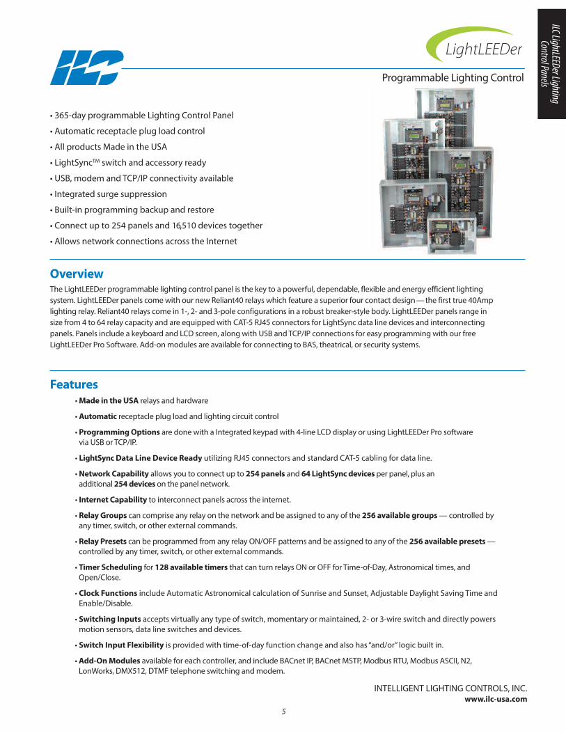
Overview The LightLEEDer programmable lighting control panel is the key to a powerful, dependable, flexible and energy efficient lighting system. LightLEEDer panels come with our new Reliant40 relays which feature a superior four contact design—the first true 40Amplighting relay. Reliant40 relays come in 1-, 2- and 3-pole configurations in a robust breaker-style body. LightLEEDer panels range insize from 4 to 64 relay capacity and are equipped with CAT-5 RJ45 connectors for LightSync data line devices and interconnectingpanels. Panels include a keyboard and LCD screen, along with USB and TCP/IP connections for easy programming with our freeLightLEEDer Pro Software. Add-on modules are available for connecting to BAS, theatrical, or security systems.
• 365-day programmable Lighting Control Panel
• Automatic receptacle plug load control
• All products Made in the USA
• LightSyncTM switch and accessory ready
• USB, modem and TCP/IP connectivity available
• Integrated surge suppression
• Built-in programming backup and restore
• Connect up to 254 panels and 16,510 devices together
• Allows network connections across the Internet
• Made in the USA relays and hardware
• Automatic receptacle plug load and lighting circuit control
• Programming Options are done with a Integrated keypad with 4-line LCD display or using LightLEEDer Pro software via USB or TCP/IP.
• LightSync Data Line Device Ready utilizing RJ45 connectors and standard CAT-5 cabling for data line.
• Network Capability allows you to connect up to 254 panels and 64 LightSync devices per panel, plus an additional 254 devices on the panel network.
• Internet Capability to interconnect panels across the internet.
• Relay Groups can comprise any relay on the network and be assigned to any of the 256 available groups — controlled byany timer, switch, or other external commands.
• Relay Presets can be programmed from any relay On/OFF patterns and be assigned to any of the 256 available presets —controlled by any timer, switch, or other external commands.
• Timer Scheduling for 128 available timers that can turn relays On or OFF for Time-of-Day, Astronomical times, andOpen/Close.
• Clock Functions include Automatic Astronomical calculation of Sunrise and Sunset, Adjustable Daylight Saving Time andEnable/Disable.
• Switching Inputs accepts virtually any type of switch, momentary or maintained, 2- or 3-wire switch and directly powersmotion sensors, data line switches and devices.
• Switch Input Flexibility is provided with time-of-day function change and also has “and/or” logic built in.
• Add-On Modules available for each controller, and include BACnet IP, BACnet MSTP, Modbus RTU, Modbus ASCII, n2, LonWorks, DMX512, DTMF telephone switching and modem.
Features
InTELLIGEnT LIGHTInG COnTROLS, InC.www.ilc-usa.com
5
Programmable Lighting Control
6
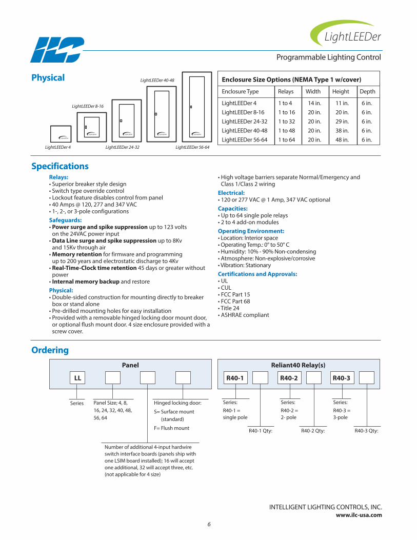
Enclosure Size Options (NEMA Type 1 w/cover)
Enclosure Type Relays Width Height Depth
LightLEEDer 4 1 to 4 14 in. 11 in. 6 in.LightLEEDer 8-16 1 to 16 20 in. 20 in. 6 in.LightLEEDer 24-32 1 to 32 20 in. 29 in. 6 in.LightLEEDer 40-48 1 to 48 20 in. 38 in. 6 in.LightLEEDer 56-64 1 to 64 20 in. 48 in. 6 in.
Relays:• Superior breaker style design• Switch type override control• Lockout feature disables control from panel• 40 Amps @ 120, 277 and 347 VAC• 1-, 2-, or 3-pole configurationsSafeguards:• Power surge and spike suppression up to 123 volts
on the 24VAC power input• Data Line surge and spike suppression up to 8Kv
and 15Kv through air• Memory retention for firmware and programming
up to 200 years and electrostatic discharge to 4Kv• Real-Time-Clock time retention 45 days or greater without
power• Internal memory backup and restorePhysical:• Double-sided construction for mounting directly to breaker
box or stand alone• Pre-drilled mounting holes for easy installation• Provided with a removable hinged locking door mount door,
or optional flush mount door. 4 size enclosure provided with ascrew cover.
• High voltage barriers separate normal/Emergency and Class 1/Class 2 wiring
Electrical:• 120 or 277 VAC @ 1 Amp, 347 VAC optionalCapacities:• Up to 64 single pole relays• 2 to 4 add-on modulesOperating Environment:• Location: Interior space• Operating Temp.: 0° to 50° C • Humidity: 10% - 90% non-condensing • Atmosphere: non-explosive/corrosive • Vibration: StationaryCertifications and Approvals:• UL • CUL• FCC Part 15• FCC Part 68• Title 24• ASHRAE compliant
Ordering
Programmable Lighting Control
Panel Size; 4, 8,16, 24, 32, 40, 48,56, 64
Series
number of additional 4-input hardwireswitch interface boards (panels ship withone LSIM board installed); 16 will accept one additional, 32 will accept three, etc. (not applicable for 4 size)
Series:R40-1 = single pole
R40-1 Qty:
Hinged locking door:
S= Surface mount (standard)
F= Flush mount
LL R40-1 R40-2 R40-3
Panel
Series:R40-2 = 2- pole
R40-2 Qty: R40-3 Qty:
Series:R40-3 = 3-pole
LightLEEDer 4 LightLEEDer 24-32 LightLEEDer 56-64
LightLEEDer 8-16
LightLEEDer 40-48Physical
Specifications
InTELLIGEnT LIGHTInG COnTROLS, InC.www.ilc-usa.com
Reliant40 Relay(s)
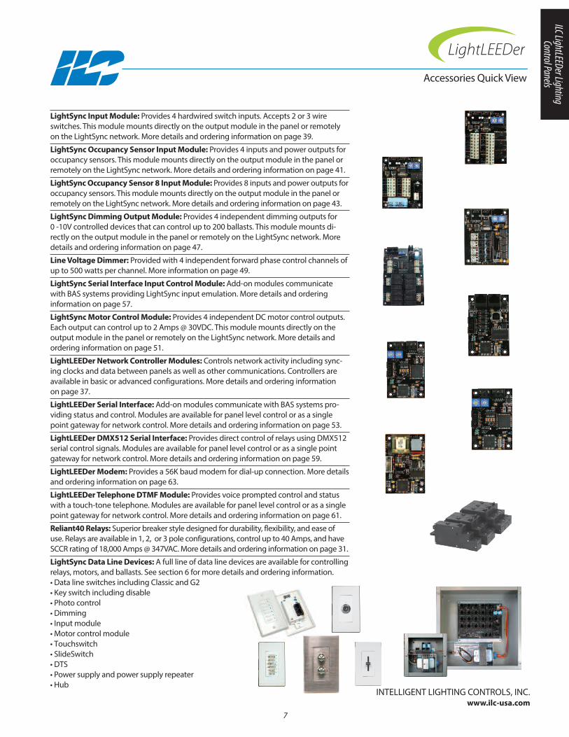
LightSync Input Module: Provides 4 hardwired switch inputs. Accepts 2 or 3 wireswitches. This module mounts directly on the output module in the panel or remotelyon the LightSync network. More details and ordering information on page 39.
LightSync Occupancy Sensor Input Module: Provides 4 inputs and power outputs for occupancy sensors. This module mounts directly on the output module in the panel or remotely on the LightSync network. More details and ordering information on page 41.
LightSync Occupancy Sensor 8 Input Module: Provides 8 inputs and power outputs foroccupancy sensors. This module mounts directly on the output module in the panel orremotely on the LightSync network. More details and ordering information on page 43.
LightSync Dimming Output Module: Provides 4 independent dimming outputs for 0 -10V controlled devices that can control up to 200 ballasts. This module mounts di-rectly on the output module in the panel or remotely on the LightSync network. Moredetails and ordering information on page 47.
Line Voltage Dimmer: Provided with 4 independent forward phase control channels ofup to 500 watts per channel. More information on page 49.
LightSync Serial Interface Input Control Module: Add-on modules communicatewith BAS systems providing LightSync input emulation. More details and ordering information on page 57.
LightSync Motor Control Module: Provides 4 independent DC motor control outputs.Each output can control up to 2 Amps @ 30VDC. This module mounts directly on theoutput module in the panel or remotely on the LightSync network. More details and ordering information on page 51.
LightLEEDer Network Controller Modules: Controls network activity including sync-ing clocks and data between panels as well as other communications. Controllers areavailable in basic or advanced configurations. More details and ordering information on page 37.
LightLEEDer Serial Interface: Add-on modules communicate with BAS systems pro-viding status and control. Modules are available for panel level control or as a singlepoint gateway for network control. More details and ordering information on page 53.
LightLEEDer DMX512 Serial Interface: Provides direct control of relays using DMX512serial control signals. Modules are available for panel level control or as a single pointgateway for network control. More details and ordering information on page 59.
LightLEEDer Modem: Provides a 56K baud modem for dial-up connection. More detailsand ordering information on page 63.
LightLEEDer Telephone DTMF Module: Provides voice prompted control and statuswith a touch-tone telephone. Modules are available for panel level control or as a singlepoint gateway for network control. More details and ordering information on page 61.
Reliant40 Relays: Superior breaker style designed for durability, flexibility, and ease ofuse. Relays are available in 1, 2, or 3 pole configurations, control up to 40 Amps, and haveSCCR rating of 18,000 Amps @ 347VAC. More details and ordering information on page 31.
LightSync Data Line Devices: A full line of data line devices are available for controllingrelays, motors, and ballasts. See section 6 for more details and ordering information.• Data line switches including Classic and G2 • Key switch including disable • Photo control• Dimming• Input module• Motor control module• Touchswitch• SlideSwitch• DTS• Power supply and power supply repeater• Hub
Accessories Quick View
7
InTELLIGEnT LIGHTInG COnTROLS, InC.www.ilc-usa.com
ILC LightLEEDer Lighting Control Panels

8
LightLEEDer 2 Load Room Controller
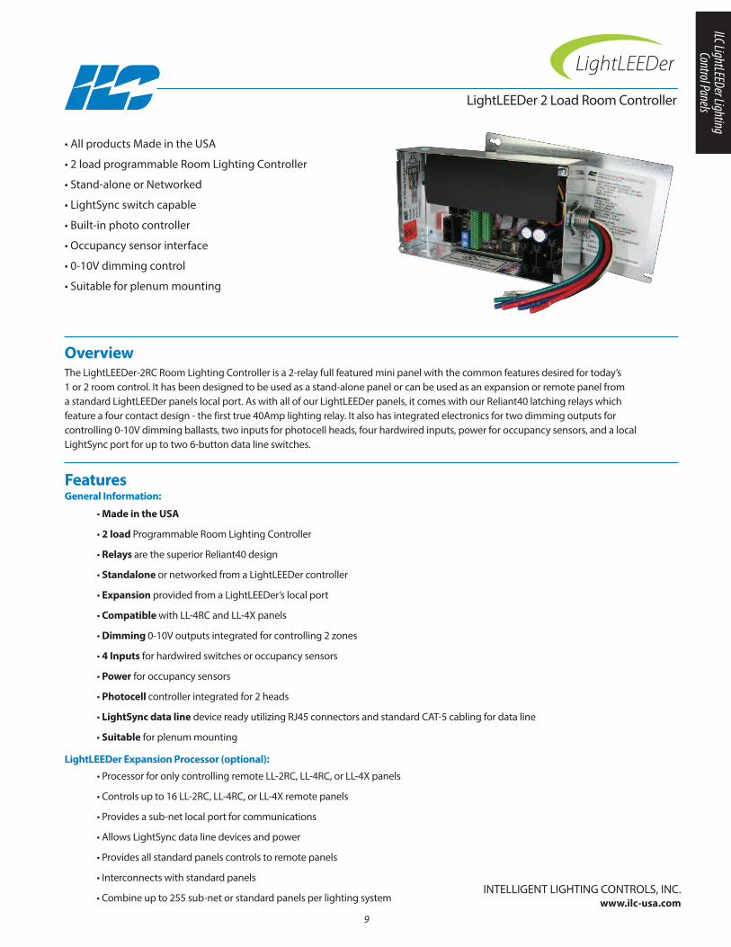
Overview The LightLEEDer-2RC Room Lighting Controller is a 2-relay full featured mini panel with the common features desired for today’s 1 or 2 room control. It has been designed to be used as a stand-alone panel or can be used as an expansion or remote panel from a standard LightLEEDer panels local port. As with all of our LightLEEDer panels, it comes with our Reliant40 latching relays which feature a four contact design - the first true 40Amp lighting relay. It also has integrated electronics for two dimming outputs for controlling 0-10V dimming ballasts, two inputs for photocell heads, four hardwired inputs, power for occupancy sensors, and a localLightSync port for up to two 6-button data line switches.
• All products Made in the USA
• 2 load programmable Room Lighting Controller
• Stand-alone or networked
• LightSync switch capable
• Built-in photo controller
• Occupancy sensor interface
• 0-10V dimming control
• Suitable for plenum mounting
Features General Information:
• Made in the USA
• 2 load Programmable Room Lighting Controller
• Relays are the superior Reliant40 design
• Standalone or networked from a LightLEEDer controller
• Expansion provided from a LightLEEDer’s local port
• Compatible with LL-4RC and LL-4X panels
• Dimming 0-10V outputs integrated for controlling 2 zones
• 4 Inputs for hardwired switches or occupancy sensors
• Power for occupancy sensors
• Photocell controller integrated for 2 heads
• LightSync data line device ready utilizing RJ45 connectors and standard CAT-5 cabling for data line
• Suitable for plenum mounting
• Processor for only controlling remote LL-2RC, LL-4RC, or LL-4X panels
• Controls up to 16 LL-2RC, LL-4RC, or LL-4X remote panels
• Provides a sub-net local port for communications
• Allows LightSync data line devices and power
• Provides all standard panels controls to remote panels
• Interconnects with standard panels
• Combine up to 255 sub-net or standard panels per lighting systemInTELLIGEnT LIGHTInG COnTROLS, InC.
www.ilc-usa.com9
LightLEEDer Expansion Processor (optional):
ILC LightLEEDer Lighting Control Panels

Safeguards:• Power surge and spike suppression up to 123 volts
on the 24VAC power input• Memory retention for firmware and programming up to
200 years and electrostatic discharge to 4kvPhysical:• Enclosure: 5” x 9” x 2” nEMA 1 with screw cover• 3/4” nipple for mounting to an electrical box• 6” wire leads provided for high voltage connections• Push-to-connect low voltage connections• Provided with pre-drilled mounting holes• High voltage barriers separate Class 2 wiringIntegrated Interfaces:• 4 inputs for hard wired switches or occupancy sensors• Power for occupancy sensors• Dimming 0-10V outputs for controlling 2 zones• Photocell controller for 2 heads or zones• LightSync port for up to 2 data line switches
Electrical:• 120/277VAC @.6 amps (120/347VAC Optional)• Input: 24 VDC @ 200mA maximum draw• Dimming: 100mA sinkRelays:• Superior breaker style design• 40 amp relays de-rated to 30 amps • 30 Amps ballast or resistive loads• SCCR to 18,000 symmetrical ampsOperating Environment:• Location: Interior space• Operating Temperature: 0° to 50° C • Humidity: 10% - 90% non-condensing • Atmosphere: non-explosive/corrosive • Vibration: StationaryCertifications and Approvals:• UL and CUL listed• FCC Part 15• Title 24• ASHRAE compliant
Ordering
LightLEEDer 2 Load Room Controller
120/277VAC = Blank120/347VAC = C
Controller
Head quantity
Physical
Specifications
InTELLIGEnT LIGHTInG COnTROLS, InC.www.ilc-usa.com
Photocell Head: Indoor (InD) only
- -IND
Expansion Processor
LL-EPSee LL-EP cut sheet
for more details
LL-EP
10
Series: LightLEEDer 2 LoadRoom Controller
LL-2RC -
5”
9”
2” Deep
3/4” nipple

LightLEEDer 4 Load Room Controller
Overview The LightLEEDer-4RC Room Lighting Controller is a 4-relay full featured panel with the common features desired for today’s 1 or 2room control. It has been designed to be used as a stand-alone panel or can be used as an expansion or remote panel from a standard LightLEEDer panels local port. As with all of our LightLEEDer panels, it comes with our Reliant40 latching relays which feature a four contact design - the first true 40Amp lighting relay. It also has integrated electronics for four dimming outputs for controlling 0-10V dimming ballasts, two inputs for photocell heads, four hardwired inputs, power for occupancy sensors, and a localLightSync port for up to two 6-button data line switches.
• All products Made in the USA
• 4 load programmable Room Lighting Controller
• Automatic receptacle plug load control
• Stand-alone or networked
• LightSync switch capable
• Built-in photo controller
• Occupancy sensor interface
• 0-10V dimming control
• Suitable for plenum mounting
Features General Information:
• Made in the USA
• Automatic receptacle plug load and lighting circuit control
• 4 load Programmable Room Lighting Controller
• Relays are the superior Reliant40 design
• Standalone or networked from a LightLEEDer controller
• Expansion provided from a LightLEEDer’s local port
• Compatible with LL-2RC and LL-4X panels
• Dimming 0-10V outputs integrated for controlling 4 zones
• 4 Inputs for hardwired switches or occupancy sensors
• Power for occupancy sensors
• Photocell controller integrated for 2 heads
• LightSync data line device ready utilizing RJ45 connectors and standard CAT-5 cabling for data line
• Suitable for plenum mounting
• Processor for only controlling remote LL-4RC, LL-2RC, or LL-4X panels
• Controls up to 16 LL-4RC, LL-2RC, or LL-4X remote panels
• Provides a sub-net local port for communications
• Allows LightSync data line devices and power
• Provides all standard panels controls to remote panels
• Interconnects with standard panels
• Combine up to 255 sub-net or standard panels per lighting systemInTELLIGEnT LIGHTInG COnTROLS, InC.
www.ilc-usa.com11
LightLEEDer Expansion Processor (optional):
ILC LightLEEDer Lighting Control Panels
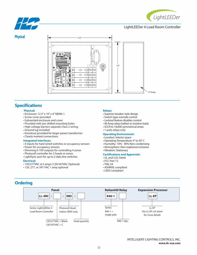
Physical:• Enclosure: 12.5” x 10” x 4” nEMA 1• Screw cover provided• Galvanized enclosure and cover• Provided with pre-drilled mounting holes• High voltage barriers separate Class 2 wiring• Ground lug included• Knockout provided for larger power transformer• Clearly marked connectionsIntegrated Interfaces:• 4 inputs for hard wired switches or occupancy sensors• Power for occupancy sensors• Dimming 0-10V outputs for controlling 4 zones• Photocell controller for 2 heads or zones• LightSync port for up to 2 data line switchesElectrical:• 120/277VAC @.5 amps (120/347VAC Optional)• 120, 277, or 347 VAC 1 amp optional
Relays:• Superior breaker style design• Switch type override control• Lockout feature disables control• 40 Amp relays ballast or resistive loads • SCCR to 18,000 symmetrical amps• 1-pole relays onlyOperating Environment:• Location: Interior space• Operating Temperature: 0° to 50° C • Humidity: 10% - 90% non-condensing • Atmosphere: non-explosive/corrosive • Vibration: StationaryCertifications and Approvals:• UL and CUL listed• FCC Part 15• Title 24• ASHRAE compliant• LEED compliant
Ordering
LightLEEDer 4 Load Room Controller
Physical
Specifications
InTELLIGEnT LIGHTInG COnTROLS, InC.www.ilc-usa.com
12
Series: LightLEEDer 4Load Room Controller
LL-4RC
Panel Expansion Processor
LL-EPSee LL-EP cut sheet
for more details
LL-EP
Series:R40-1 = single pole
R40-1 Qty:
R40-1
Reliant40 Relay
120/277VAC = Blank120/347VAC = C
- -
LSOUT
OUTIN
10”
12.5”
4” Deep
Photocell Head: Indoor (InD) only
IND
Head quantity
-
LightLEEDer-4X Remote/Expansion Lighting Controller
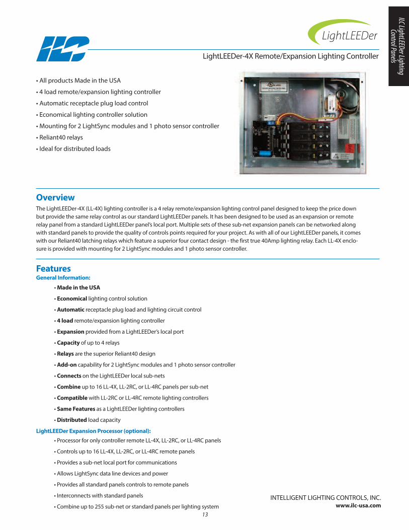
Overview The LightLEEDer-4X (LL-4X) lighting controller is a 4 relay remote/expansion lighting control panel designed to keep the price downbut provide the same relay control as our standard LightLEEDer panels. It has been designed to be used as an expansion or remoterelay panel from a standard LightLEEDer panel’s local port. Multiple sets of these sub-net expansion panels can be networked alongwith standard panels to provide the quality of controls points required for your project. As with all of our LightLEEDer panels, it comeswith our Reliant40 latching relays which feature a superior four contact design - the first true 40Amp lighting relay. Each LL-4X enclo-sure is provided with mounting for 2 LightSync modules and 1 photo sensor controller.
• All products Made in the USA
• 4 load remote/expansion lighting controller
• Automatic receptacle plug load control
• Economical lighting controller solution
• Mounting for 2 LightSync modules and 1 photo sensor controller
• Reliant40 relays
• Ideal for distributed loads
Features General Information:
• Made in the USA
• Economical lighting control solution
• Automatic receptacle plug load and lighting circuit control
• 4 load remote/expansion lighting controller
• Expansion provided from a LightLEEDer’s local port
• Capacity of up to 4 relays
• Relays are the superior Reliant40 design
• Add-on capability for 2 LightSync modules and 1 photo sensor controller
• Connects on the LightLEEDer local sub-nets
• Combine up to 16 LL-4X, LL-2RC, or LL-4RC panels per sub-net
• Compatible with LL-2RC or LL-4RC remote lighting controllers
• Same Features as a LightLEEDer lighting controllers
• Distributed load capacity
13
• Processor for only controller remote LL-4X, LL-2RC, or LL-4RC panels
• Controls up to 16 LL-4X, LL-2RC, or LL-4RC remote panels
• Provides a sub-net local port for communications
• Allows LightSync data line devices and power
• Provides all standard panels controls to remote panels
• Interconnects with standard panels
• Combine up to 255 sub-net or standard panels per lighting system
LightLEEDer Expansion Processor (optional):
InTELLIGEnT LIGHTInG COnTROLS, InC.www.ilc-usa.com
ILC LightLEEDer Lighting Control Panels

Physical:• Enclosure: 12.5” x 10” x 4” nEMA 1• Screw cover provided• Galvanized enclosure and cover• Provided with pre-drilled mounting holes• High voltage barriers separate Class 2 wiring• Ground lug included• Knockout provided for larger power transformer• Clearly marked connectionsElectrical:• 120/277VAC @.5 amps (120/347VAC Optional)• 120, 277, or 347 VAC 1 amp optional
Relays:• Superior breaker style design• Switch type override control• Lockout feature disables control• 40 Amp relays ballast or resistive loads • SCCR to 18,000 symmetrical amps• 1-pole relays onlyOperating Environment:• Location: Interior space• Operating Temperature: 0° to 50° C • Humidity: 10% - 90% non-condensing • Atmosphere: non-explosive/corrosive • Vibration: StationaryCertifications and Approvals:• UL and CUL listed• FCC Part 15• Title 24• ASHRAE compliant• LEED compliant
Ordering
LightLEEDer-4X Remote/Expansion Lighting Controller
LightLEEDer-4X Remote/ExpansionLighting Controller
LL-4X
Panel Expansion Processor
Physical
Specifications
InTELLIGEnT LIGHTInG COnTROLS, InC.www.ilc-usa.com
LL-EPSee LL-EP cut sheet
for more details
LL-EP
14
Series:R40-1 = single pole
R40-1 Qty:
R40-1
Reliant40 Relay
120/277VAC = Blank120/347VAC = C
-
10”
12.5”
4” Deep
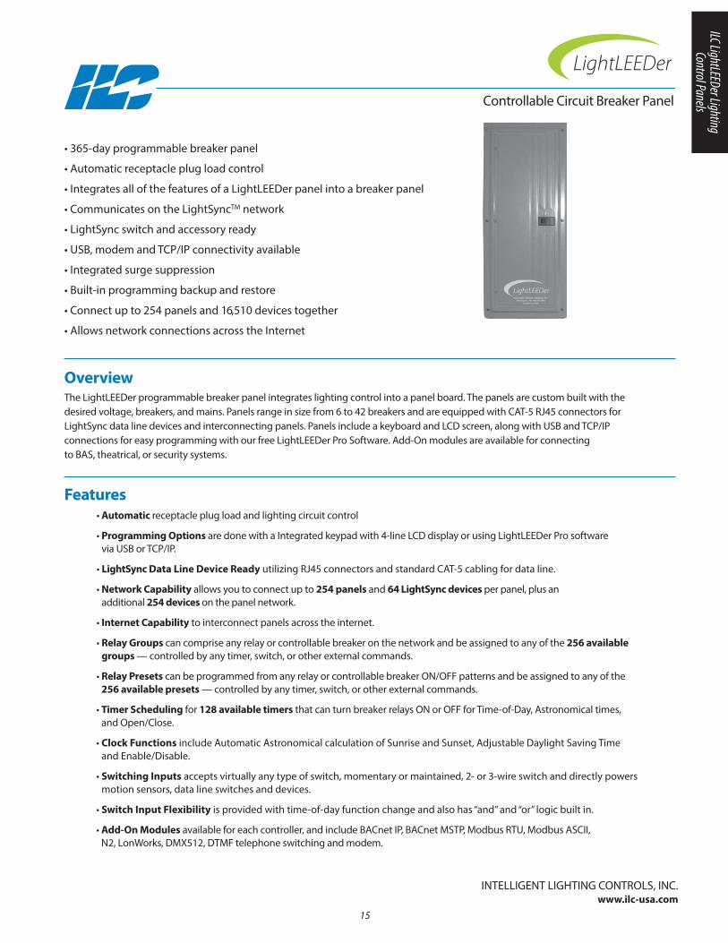
Overview The LightLEEDer programmable breaker panel integrates lighting control into a panel board. The panels are custom built with the desired voltage, breakers, and mains. Panels range in size from 6 to 42 breakers and are equipped with CAT-5 RJ45 connectors forLightSync data line devices and interconnecting panels. Panels include a keyboard and LCD screen, along with USB and TCP/IP connections for easy programming with our free LightLEEDer Pro Software. Add-On modules are available for connecting to BAS, theatrical, or security systems.
• 365-day programmable breaker panel
• Automatic receptacle plug load control
• Integrates all of the features of a LightLEEDer panel into a breaker panel
• Communicates on the LightSyncTM network
• LightSync switch and accessory ready
• USB, modem and TCP/IP connectivity available
• Integrated surge suppression
• Built-in programming backup and restore
• Connect up to 254 panels and 16,510 devices together
• Allows network connections across the Internet
• Automatic receptacle plug load and lighting circuit control
• Programming Options are done with a Integrated keypad with 4-line LCD display or using LightLEEDer Pro software via USB or TCP/IP.
• LightSync Data Line Device Ready utilizing RJ45 connectors and standard CAT-5 cabling for data line.
• Network Capability allows you to connect up to 254 panels and 64 LightSync devices per panel, plus an additional 254 devices on the panel network.
• Internet Capability to interconnect panels across the internet.
• Relay Groups can comprise any relay or controllable breaker on the network and be assigned to any of the 256 availablegroups — controlled by any timer, switch, or other external commands.
• Relay Presets can be programmed from any relay or controllable breaker On/OFF patterns and be assigned to any of the256 available presets — controlled by any timer, switch, or other external commands.
• Timer Scheduling for 128 available timers that can turn breaker relays On or OFF for Time-of-Day, Astronomical times, and Open/Close.
• Clock Functions include Automatic Astronomical calculation of Sunrise and Sunset, Adjustable Daylight Saving Time and Enable/Disable.
• Switching Inputs accepts virtually any type of switch, momentary or maintained, 2- or 3-wire switch and directly powersmotion sensors, data line switches and devices.
• Switch Input Flexibility is provided with time-of-day function change and also has “and” and “or” logic built in.
• Add-On Modules available for each controller, and include BACnet IP, BACnet MSTP, Modbus RTU, Modbus ASCII, n2, LonWorks, DMX512, DTMF telephone switching and modem.
Features
InTELLIGEnT LIGHTInG COnTROLS, InC.www.ilc-usa.com
Controllable Circuit Breaker Panel
15
ILC LightLEEDer Lighting Control Panels
16
Breakers:• 1 or 2 pole controllable breakers
1-, 2-, or 3-pole standard breakers• Amperage: 15 to 100 Amp• Mains: Lugs or breakers -100, 225, 400, and 600 Amp• Voltage: 120/240, 208/120, 480/277 VACPhysical:• 16 gauge nEMA 1 enclosures• Provided with pre-drilled mounting holes • Provided with a hinged locking door for flush or surface
mountingPower Supply:• 120 or 277 VAC @ 1 Amp, 347 VAC optional
Capacities:• Up to 42 breakers• 2 to 4 add-on modulesOperating Environment:• Location: Interior space• Operating Temp.: 0° to 50° C • Humidity: 10% - 90% non-condensing • Atmosphere: non-explosive/corrosive • Vibration: StationaryCertifications and Approvals:• UL and CUL Listed
Physical
Specifications
InTELLIGEnT LIGHTInG COnTROLS, InC.www.ilc-usa.com
Controllable Circuit Breaker Panel
Ordering
Contact ILC for ordering information
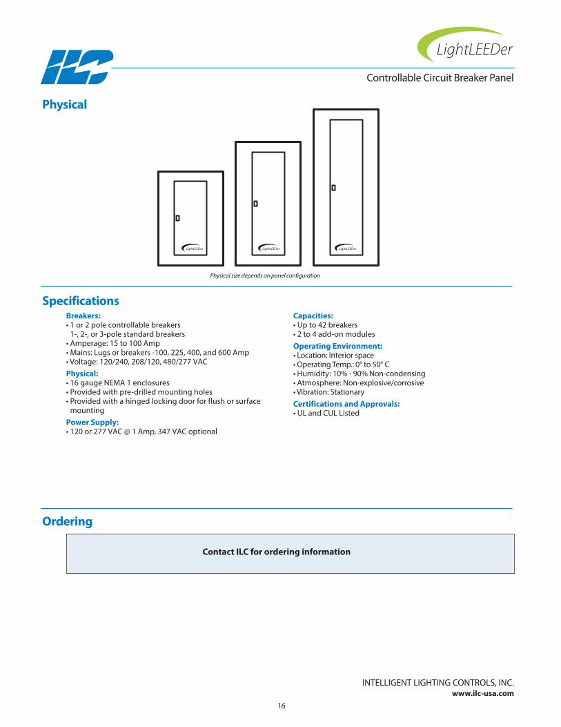
Physical size depends on panel configuration
Section 2: LightLEEDer Common Add-on Devices
• LightSync Input Module
• LightSync Occupancy Sensor Input
• LightSync Occupancy Sensor 8 Input Module
• LightLEEDer network Controller Module
• LightLEEDer Serial Interface Control Modules
• LightSync Dimming Module
• LightSync LVD Line Voltage Dimmer
• LightSync Power Supply Repeater, Power Supply
• LightSync Expansion Processor
17
LightLEEDer Comm
on Add-on Devices

18

Overview The LightSync Input Module is designed to accept up to 4 hardwired switch inputs. Each input accepts a 2 or 3 wire dry contactswitch closure or an equivalent open collect signal from any source. Each input module can also be configured to accept a 12-24VDC signal from security or BAS systems. Any input can be programmed to control any relay(s), group(s), or preset(s) in any or allpanels. Each input has an associated pilot status LED output that indicates the true status of any relay, group, or preset. It may alsobe programmed to a reverse status (LED is On if the relay is OFF) or On always. Inputs have a time-of-day or open/close time of action function which could disable the input or change the input type.
• Provides hardwired inputs
• Installs directly onto output board or remotely
• 4 inputs per module
• Made in the USA
• Easy non-screw push-to-connect terminals
• Optically isolated inputs protect electronics
• Accepts dry contact closures or 12-24 VDC signals
• LED pilot outputs for true relay, group, or preset status
• 4 hardwire inputs and status outputs per module
• Made in the USA
• Installs directly onto the output board
• Digitally addressable device for a unique address
• Remote mounting option for LightSync network
• RJ45 connectors for remote mounting module
• Terminals are an easy non-screw push-to-connect type
• Optically isolated inputs that protect the electronics
• Accepts dry contact closures or open collector outputs
• Configurable to accept 12-24 VDC signals
• Accepts 2 or 3 wire momentary or maintained switches
• Associated LED pilot output is provided for each input
• True status pilot for relay, group, or presets
Features General Information:
InTELLIGEnT LIGHTInG COnTROLS, InC.www.ilc-usa.com
Hardwired Device Interface
Input Module
• Remote mount anywhere on the LightSync network
• Self powered from the network
• RJ45 connectors provided for easy connection
• Mounting plate available
• Great choice for a central switch control station. Eliminates wiring individual switches to panels - only a data line required
Remote Mounting Option:
19
LightLEEDer Comm
on Add-on Devices
1 ON
1 PILOT
1 OFF
1 COM
3 ON
3 OFF
3 COM
3 PILOT
2 ON
2 PILOT
2 OFF
2 COM
4 ON
4 OFF
4 COM
EXT +V
EXTCOM
4 PILOT
OUTIN
77013485A
1 ON
1 PILOT
1 OFF
1 COM
3 ON
3 OFF
3 COM
3 PILOT
2 ON
2 PILOT
2 OFF
2 COM
4 ON
4 OFF
4 COM
EXT +V
EXTCOM
4 PILOT
OUTIN
77013485A
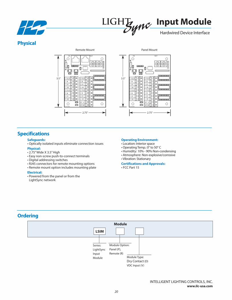
Remote Mount Panel Mount
3.5”
2.75”
3.5”
2.75”
Safeguards:• Optically isolated inputs eliminate connection issuesPhysical:• 2.75” Wide X 3.5” High• Easy non-screw push-to-connect terminals• Digital addressing switches• RJ45 connectors for remote mounting options• Remote mount option includes mounting plateElectrical:• Powered from the panel or from the
LightSync network
Operating Environment:• Location: Interior space• Operating Temp.: 0° to 50° C • Humidity: 10% - 90% non-condensing • Atmosphere: non-explosive/corrosive • Vibration: StationaryCertifications and Approvals:• FCC Part 15
Physical
Specifications
Ordering Module
Hardwired Device Interface
Input Module
InTELLIGEnT LIGHTInG COnTROLS, InC.www.ilc-usa.com
Module Type: Dry Contact (D) VDC Input (V)
Series:LightSyncInput Module
LSIM
Module Option: Panel (P), Remote (R)
20
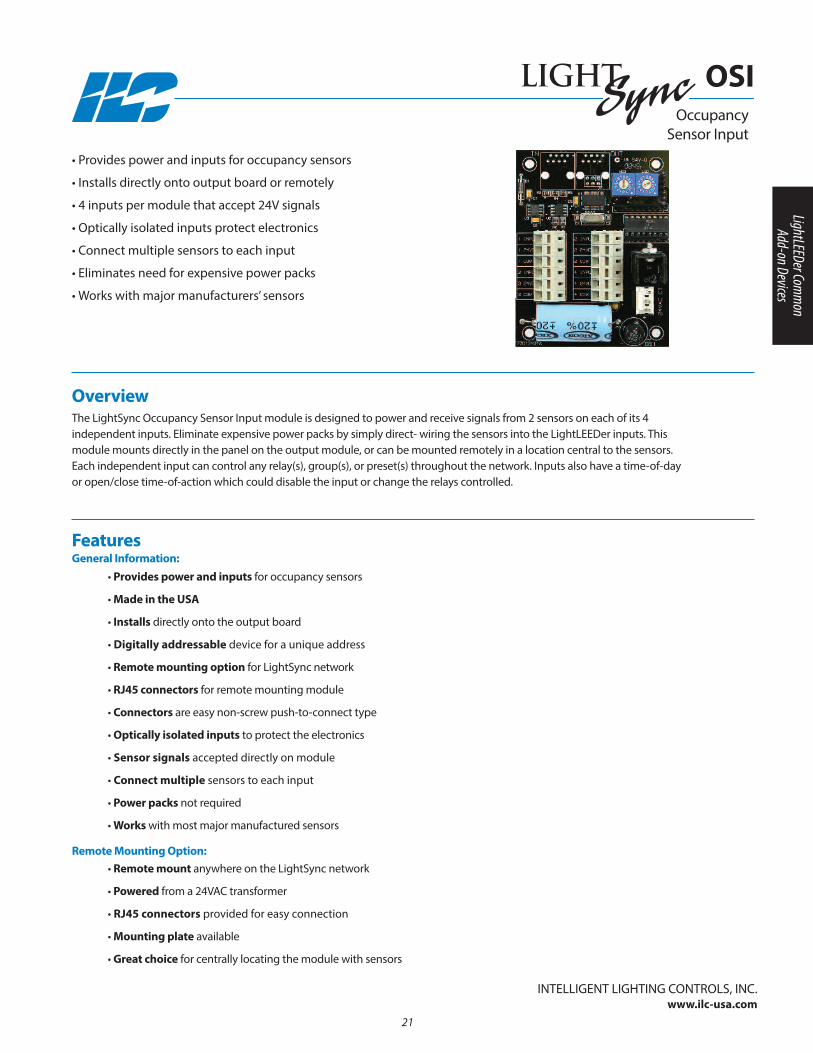
Overview The LightSync Occupancy Sensor Input module is designed to power and receive signals from 2 sensors on each of its 4 independent inputs. Eliminate expensive power packs by simply direct- wiring the sensors into the LightLEEDer inputs. This module mounts directly in the panel on the output module, or can be mounted remotely in a location central to the sensors. Each independent input can control any relay(s), group(s), or preset(s) throughout the network. Inputs also have a time-of-day or open/close time-of-action which could disable the input or change the relays controlled.
• Provides power and inputs for occupancy sensors
• Installs directly onto output board or remotely
• 4 inputs per module that accept 24V signals
• Optically isolated inputs protect electronics
• Connect multiple sensors to each input
• Eliminates need for expensive power packs
• Works with major manufacturers’ sensors
Occupancy Sensor Input
• Provides power and inputs for occupancy sensors
• Made in the USA
• Installs directly onto the output board
• Digitally addressable device for a unique address
• Remote mounting option for LightSync network
• RJ45 connectors for remote mounting module
• Connectors are easy non-screw push-to-connect type
• Optically isolated inputs to protect the electronics
• Sensor signals accepted directly on module
• Connect multiple sensors to each input
• Power packs not required
• Works with most major manufactured sensors
• Remote mount anywhere on the LightSync network
• Powered from a 24VAC transformer
• RJ45 connectors provided for easy connection
• Mounting plate available
• Great choice for centrally locating the module with sensors
FeaturesGeneral Information:
Remote Mounting Option:
InTELLIGEnT LIGHTInG COnTROLS, InC.www.ilc-usa.com
OSI
21
LightLEEDer Comm
on Add-on Devices

1 24VDC
1 INPUT
1 COM
3 INPUT
3 COM
3 24VDC
2 24VDC
2 INPUT
2 COM
4 INPUT
4 COM
4 24VDC
OUTIN
77013494A
24VAC CT
1 24VDC
1 INPUT
1 COM
3 INPUT
3 COM
3 24VDC
2 24VDC
2 INPUT
2 COM
4 INPUT
4 COM
4 24VDC
OUTIN
77013494A
24VAC CT
Remote Mount Panel Mount
3.5”
2.75”
3.5”
2.75”
Occupancy Sensor Input
OSI
Safeguards:• Optically isolated inputs protect electronicsPhysical:• 2.75” W x 3.5” H• Easy non-screw push-to-connect connectors• Digital addressing switches• RJ45 connectors for remote mounting option• Remote mount option includes mounting plate
and transformerElectrical:• Powered from panel transformer (remote option powered by
24VAC transformer).• 200mA @ 24VDC maximum draw per module
Operating Environment:• Location: Interior space• Operating Temp.: 0° to 50° C • Humidity: 10% - 90% non-condensing • Atmosphere: non-explosive/corrosive • Vibration: StationaryCertifications and Approvals:• FCC Part 15
Physical
Specifications
InTELLIGEnT LIGHTInG COnTROLS, InC.www.ilc-usa.com
Ordering
Series:LightSync Occupancy Sensor Input
LSOSI
Device
Mounting: P = PanelR = Remote
22
InTELLIGEnT LIGHTInG COnTROLS, InC.www.ilc-usa.com
23
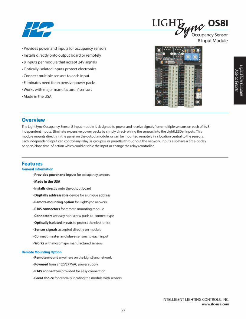
Overview The LightSync Occupancy Sensor 8 Input module is designed to power and receive signals from multiple sensors on each of its 8 independent inputs. Eliminate expensive power packs by simply direct- wiring the sensors into the LightLEEDer inputs. This module mounts directly in the panel on the output module, or can be mounted remotely in a location central to the sensors. Each independent input can control any relay(s), group(s), or preset(s) throughout the network. Inputs also have a time-of-day or open/close time-of-action which could disable the input or change the relays controlled.
• Provides power and inputs for occupancy sensors
• Installs directly onto output board or remotely
• 8 inputs per module that accept 24V signals
• Optically isolated inputs protect electronics
• Connect multiple sensors to each input
• Eliminates need for expensive power packs
• Works with major manufacturers’ sensors
• Made in the USA
Occupancy Sensor 8 Input Module
• Provides power and inputs for occupancy sensors
• Made in the USA
• Installs directly onto the output board
• Digitally addressable device for a unique address
• Remote mounting option for LightSync network
• RJ45 connectors for remote mounting module
• Connectors are easy non-screw push-to-connect type
• Optically isolated inputs to protect the electronics
• Sensor signals accepted directly on module
• Connect master and slave sensors to each input
• Works with most major manufactured sensors
• Remote mount anywhere on the LightSync network
• Powered from a 120/277VAC power supply
• RJ45 connectors provided for easy connection
• Great choice for centrally locating the module with sensors
FeaturesGeneral Information
Remote Mounting Option
OS8I
LightLEEDer Comm
on Add-on Devices

InTELLIGEnT LIGHTInG COnTROLS, InC.www.ilc-usa.com
24
1 24VDC
1 INPUT
1 COM
2 24VDC
2 INPUT
2 COM
3 INPUT
3 COM
3 24VDC
4 INPUT
4 COM
4 24VDC
5 24VDC
5 INPUT
5 COM
6 24VDC
6 INPUT
6 COM
7 INPUT
7 COM
7 24VDC
8 INPUT
8 COM
8 24VDC
77013506B
24VAC
1 24VDC
1 INPUT
1 COM
2 24VDC
2 INPUT
2 COM
3 INPUT
3 COM
3 24VDC
4 INPUT
4 COM
4 24VDC
5 24VDC
5 INPUT
5 COM
6 24VDC
6 INPUT
6 COM
7 INPUT
7 COM
7 24VDC
8 INPUT
8 COM
8 24VDC
77013506B
24VAC
Panel Mount
6.50”
9.25”
3.5”
2.75”
Occupancy Sensor 8 Input Module
OS8I
Safeguards:• Optically isolated inputs protect electronicsPhysical:• 2.75” W x 3.5” H• Easy non-screw push-to-connect connectors• Digital addressing switches• RJ45 connectors for remote mounting optionRemote Mount Physical:• Enclosure: 6.50” x 9.25” x 2.50 ”with screw cover• 1/2”nipple for mounting to an electrical box• 6”wire leads provided for high voltage connection• Push-to-connect low voltage connections• Provided with pre-drilled mounting holes
Electrical:• Electronics powered from LightSync data line• Sensors powered from 120/277VAC power supply• Current: 800mA • Voltage: 24VDC• Current limited circuitOperating Environment:• Location: Interior space• Operating Temp.: 0° to 50° C • Humidity: 10% - 90% non-condensing • Atmosphere: non-explosive/corrosive • Vibration: StationaryCertifications and Approvals:• FCC Part 15• UL
Physical
Specifications
Ordering
Series:LightSync Occupancy Sensor 8 Input
LSOS8I
Device
Mounting: P = PanelR = Remote
-
Remote Mount
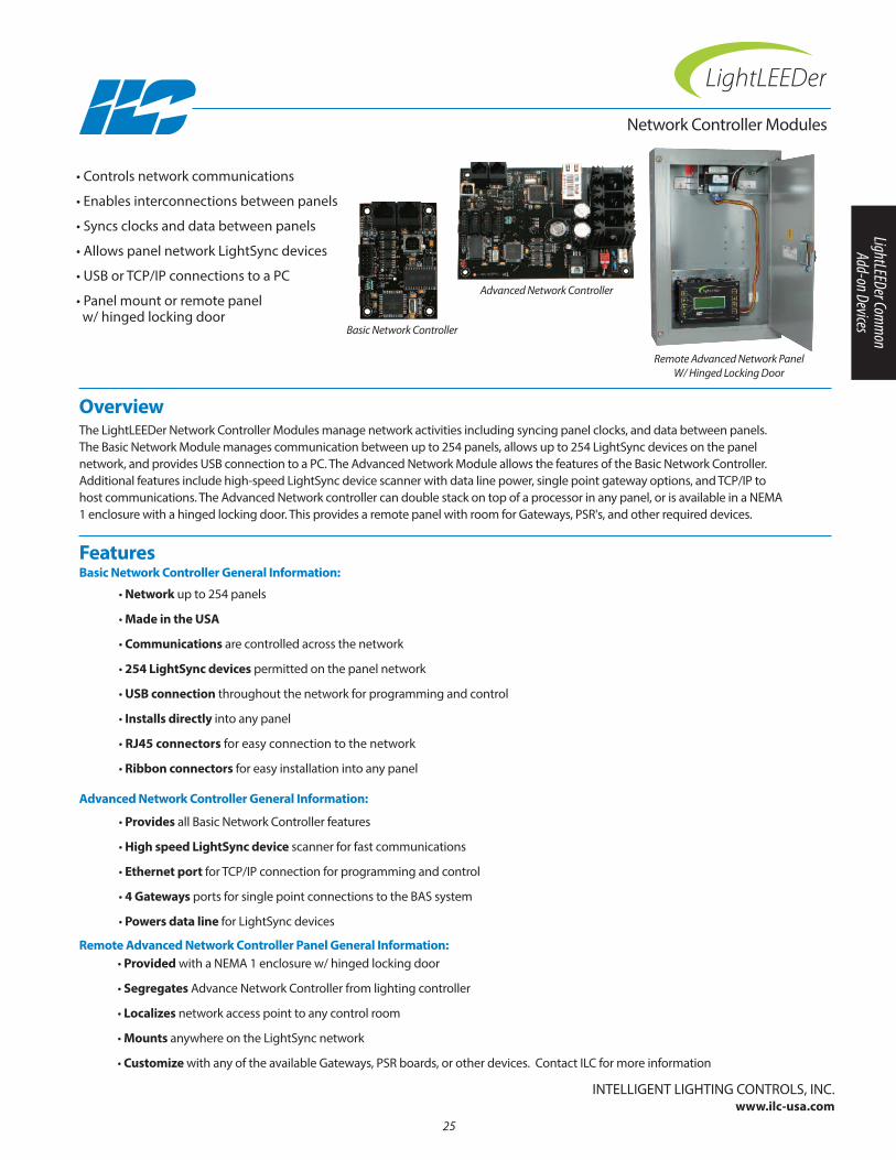
Overview The LightLEEDer network Controller Modules manage network activities including syncing panel clocks, and data between panels. The Basic network Module manages communication between up to 254 panels, allows up to 254 LightSync devices on the panel network, and provides USB connection to a PC. The Advanced network Module allows the features of the Basic network Controller. Additional features include high-speed LightSync device scanner with data line power, single point gateway options, and TCP/IP tohost communications. The Advanced network controller can double stack on top of a processor in any panel, or is available in a nEMA1 enclosure with a hinged locking door. This provides a remote panel with room for Gateways, PSR's, and other required devices.
• Controls network communications
• Enables interconnections between panels
• Syncs clocks and data between panels
• Allows panel network LightSync devices
• USB or TCP/IP connections to a PC
• Panel mount or remote panelw/ hinged locking door
network Controller Modules
• Network up to 254 panels
• Made in the USA
• Communications are controlled across the network
• 254 LightSync devices permitted on the panel network
• USB connection throughout the network for programming and control
• Installs directly into any panel
• RJ45 connectors for easy connection to the network
• Ribbon connectors for easy installation into any panel
Features Basic Network Controller General Information:
InTELLIGEnT LIGHTInG COnTROLS, InC.www.ilc-usa.com
• Provides all Basic network Controller features
• High speed LightSync device scanner for fast communications
• Ethernet port for TCP/IP connection for programming and control
• 4 Gateways ports for single point connections to the BAS system
• Powers data line for LightSync devices
• Provided with a nEMA 1 enclosure w/ hinged locking door
• Segregates Advance network Controller from lighting controller
• Localizes network access point to any control room
• Mounts anywhere on the LightSync network
• Customize with any of the available Gateways, PSR boards, or other devices. Contact ILC for more information
Advanced Network Controller General Information:
Remote Advanced Network Controller Panel General Information:
Advanced Network Controller
Remote Advanced Network PanelW/ Hinged Locking Door
Basic Network Controller
25
LightLEEDer Comm
on Add-on Devices

Panel Mount:• Basic: 2” Wide X 3” High• Advanced: 6” Wide X 4” High• Removable power connector• USB connector• RJ45 Ethernet connector Advanced Remote Panel W/ HLD:• 12" Wide X 18" High X 4" Deep• nEMA1 enclosure with knockouts• Hinged locking door provided• AnSI 61 gray finish• Mounting holes provided• High voltage dividerElectrical:• Panel Mount: Powered from panel• Remote Panel: 120/277 VAC, 1 Amp
Configuration:• Software programming• Directly through keypadOperating Environment:• Location: Interior space• Operating Temp.: 0° to 50° C • Humidity: 10% - 90% non-condensing • Atmosphere: non-explosive/corrosive • Vibration: StationaryCertifications and Approvals:• UL• CUL• FCC Part 15
Ordering
network Controller Modules
Series: LightLEEDer network ControllerModule
LLNC
Module
Type: Basic (B)Advanced (A)Advanced remote panel (A-HLD)
Physical
SpecificationsPhysical
9701349577013495A
OUTIN
OFF ON
12VAC
12VAC
CTPOWER
24VAC CT
77013491C
ALL OFFOFF ON
POWER
77013490 R1
ALL ON
Intelligent Lighting Controls, Inc.
2.0”
3.0”4.0” 18.0”
6.0”
12.0”
4.0” deep
Basic network Controller Advanced network Controller (panel mount)
Remote Advanced network Controller Panel
-
26
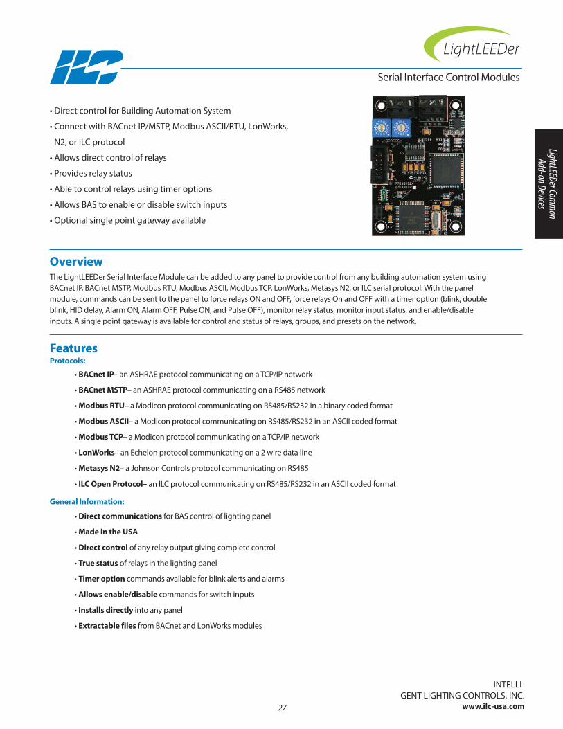
Overview The LightLEEDer Serial Interface Module can be added to any panel to provide control from any building automation system usingBACnet IP, BACnet MSTP, Modbus RTU, Modbus ASCII, Modbus TCP, LonWorks, Metasys n2, or ILC serial protocol. With the panel module, commands can be sent to the panel to force relays On and OFF, force relays On and OFF with a timer option (blink, doubleblink, HID delay, Alarm On, Alarm OFF, Pulse On, and Pulse OFF), monitor relay status, monitor input status, and enable/disable inputs. A single point gateway is available for control and status of relays, groups, and presets on the network.
• Direct control for Building Automation System
• Connect with BACnet IP/MSTP, Modbus ASCII/RTU, LonWorks,
n2, or ILC protocol
• Allows direct control of relays
• Provides relay status
• Able to control relays using timer options
• Allows BAS to enable or disable switch inputs
• Optional single point gateway available
Serial Interface Control Modules
• BACnet IP– an ASHRAE protocol communicating on a TCP/IP network
• BACnet MSTP– an ASHRAE protocol communicating on a RS485 network
• Modbus RTU– a Modicon protocol communicating on RS485/RS232 in a binary coded format
• Modbus ASCII– a Modicon protocol communicating on RS485/RS232 in an ASCII coded format
• Modbus TCP– a Modicon protocol communicating on a TCP/IP network
• LonWorks– an Echelon protocol communicating on a 2 wire data line
• Metasys N2– a Johnson Controls protocol communicating on RS485
• ILC Open Protocol– an ILC protocol communicating on RS485/RS232 in an ASCII coded format
Features Protocols:
InTELLI-GEnT LIGHTInG COnTROLS, InC.
www.ilc-usa.com
• Direct communications for BAS control of lighting panel
• Made in the USA
• Direct control of any relay output giving complete control
• True status of relays in the lighting panel
• Timer option commands available for blink alerts and alarms
• Allows enable/disable commands for switch inputs
• Installs directly into any panel
• Extractable files from BACnet and LonWorks modules
General Information:
27
LightLEEDer Comm
on Add-on Devices

Physical:• Panel Level: 2” Wide X 3” High• Gateway Level: 6” Wide X 4” High
2” Wide X 3” High• RJ45 connectors for Ethernet based
communications• Removable screw connectors for data line
communicationsElectrical:• Powered from the panel
Operating Environment:• Location: Interior space• Operating Temp.: 0° to 50° C • Humidity: 10% - 90% non-condensing • Atmosphere: non-explosive/corrosive • Vibration: StationaryCertifications and Approvals:• FCC Part 15
Ordering
Serial Interface Control Modules
Series: LightLEEDer Serial Interface Module
LLSI
Module
Protocol: BACnet IP = BACIPBACnet MSTP= BACMSTPLonWorks = LOnModbus = MODModbus TCP = MODTCPMetasys n2 = n2ILC Open = ILC
Mount: Panel Level (PL)Gateway (nG)
Physical
Specifications
OUTIN
OFF ON
12VAC
12VAC
CT
POWER
24VAC CT
77013491A
2.0”
3.0”4.0”
2.0”
3.0”
6.0”
Panel Level Module
Gateway Level Modules
- -
nOTE: Physical appearance may vary between protocols.
28

Overview The LightSync Dimming Module is designed for 0-10V device control. It can be used in conjunction with a photocell controller forprogrammable daylight harvesting. This module can be installed in the lighting control panel or remotely mounted on the LightSyncnetwork. Each of the 4 independent channels can control up to 200 ballasts with 256 steps between 0 and 10V. Outputs are designedto sink voltage, and an optional module is available with sink/source/direct drive option. Each output may be programmed to respond to 16 inputs per channel. The intuitive software provided makes it easy to program and adjust the settings. If the power islost to the standard dimming module, the output signal to the ballast will go to 10V for full brightness.
• Controls 0-10V dimmable ballast or other 0-10V devices
• Installs directly onto output board or remotely mounted
• Provides 4 independent output channels per module
• Each output is capable of driving up to 200 ballasts
• Responds to LightSync inputs, hardwired inputs, and timers
• Able to track DMX512 signals
• Standard voltage sink module or optional sink/source/direct module
• Standard module output will go to 10V upon power loss
Features General Information:
InTELLIGEnT LIGHTInG COnTROLS, InC.www.ilc-usa.com
• 4 independent channels per module provide the flexibility to control up to 4 zones
• Made in the USA
• Each output can control up to 200 typical ballasts at .5mA each
• Power-On level settings allow each output to be configured for 0 to 100% levels upon power-up
• Power Loss to dimming module sets dimming to full brightness
• LightSync photocell tracking programmed directly to output point(s)
• Each output may be programmed to respond to 16 LightSync or hardwire inputs. Each input can be programmed to force the output to a preset level, raise or lower at 10% increments, and can work in conjunction with a photocell. Inputs can be set to “revert to photocell control” after a period of time that can range from 5 to 600 minutes in 5 minute increments.
• Fade rate of 0 to 300 seconds can be programmed for each output
• Minimum and maximum output levels can be configured for each output
• With a DMX512 serial interface, each output can be controlled by any of the DMX512 signal channels
• Panel mount installs directly on output board
• Remote mounting option for LightSync network
• RJ45 connectors for remote mounting module
• Removable connectors for easy installation
• Digitally addressable
• Optional sink/source and direct drive output module
Dimming Module
DM
29
LightLEEDer Comm
on Add-on Devices
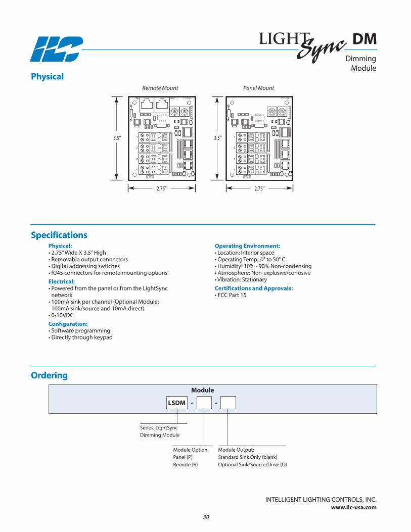
Physical:• 2.75” Wide X 3.5” High• Removable output connectors• Digital addressing switches• RJ45 connectors for remote mounting optionsElectrical:• Powered from the panel or from the LightSync
network• 100mA sink per channel (Optional Module:
100mA sink/source and 10mA direct)• 0-10VDCConfiguration:• Software programming• Directly through keypad
Operating Environment:• Location: Interior space• Operating Temp.: 0° to 50° C • Humidity: 10% - 90% non-condensing • Atmosphere: non-explosive/corrosive • Vibration: StationaryCertifications and Approvals:• FCC Part 15
Ordering
Series: LightSync Dimming Module
LSDM
Module
Module Option: Panel (P)Remote (R)
Physical
Specifications
IN
1
2
3
4
OUT 77013489B
1
2
3
4
77013489B
2.75”
3.5” 3.5”
2.75”
Remote Mount Panel Mount
-
Module Output:Standard Sink Only (blank)Optional Sink/Source/Drive (O)
-
Dimming Module
DM
InTELLIGEnT LIGHTInG COnTROLS, InC.www.ilc-usa.com
30

Overview The LightSync Line Voltage Dimmer is controlled in the ILC lighting control system network. It contains 4 independent forward phasecontrol channels capable of up to 500 watts per channel. It is designed to control incandescent, LED, and cold cathode fixtures anddim loads through the full range with smooth transitioning. Being a LightSync device, it can be directly controlled anywhere on thenetwork with photo sensors, switches, sliders, timers and more.
• Line voltage dimming
• 4 independent dimming outputs
• 500 Watts per channel
• Relay On/Off control for each channel
• Communicates on the LightSync data line
• Controls Incandescent, LED, and cold cathode loads
• Made in the USA
Features General Information:
InTELLIGEnT LIGHTInG COnTROLS, InC.www.ilc-usa.com
• Made in the USA
• 4 independent channels are provided for the flexibility to control up to 4 zones
• Forward phase solid state control
• Relay control for turning loads On/Off
• Each output is capable of controlling up to 500 watts
• Power-On level settings allow each output to be configured for 0 to 100% levels after a building power loss
• LightSync photocell tracking programmed directly to output channel(s)
• Each output may be programmed to respond to 16 LightSync or hardwire inputs. Each input can be programmedto force the output to a preset level, raise or lower at 10% increments and can work in conjunction with a photocell.Inputs can be set to "revert to photocell control" after a period of time that can range from 5 to 600 minutes in 5 minute increments.
• A fade rate of 0 to 300 seconds can be programmed for each output
• Minimum and maximum levels can be configured for each output
• With a DMX512 serial interface, each output can be controlled by any of the 512 signal channels
• Digitally addressable device for a unique address
Line Voltage Dimmer
LVD
31
LightLEEDer Comm
on Add-on Devices
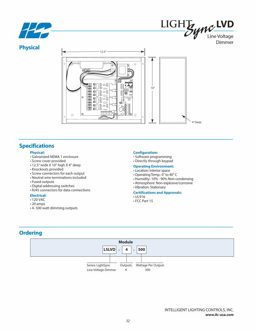
Physical:• Galvanized nEMA 1 enclosure• Screw cover provided• 12.5" wide X 10" high X 4" deep• Knockouts provided• Screw connectors for each output• neutral wire terminations included• Fused outputs• Digital addressing switches• RJ45 connectors for data connectionsElectrical:• 120 VAC• 20 amps• 4- 500 watt dimming outputs
Configuration:• Software programming• Directly through keypadOperating Environment:• Location: Interior space• Operating Temp.: 0° to 40° C • Humidity: 10% - 90% non-condensing • Atmosphere: non-explosive/corrosive • Vibration: StationaryCertifications and Approvals:• UL916• FCC Part 15
Ordering
Series: LightSync Line Voltage Dimmer
LSLVD
Module
Outputs: 4
Physical
Specifications
-
Wattage Per Output:500
-
Line Voltage Dimmer
LVD
InTELLIGEnT LIGHTInG COnTROLS, InC.www.ilc-usa.com
32
4 500
LOA
D 3
LOA
D 1
NE
UT 3
LOA
D 4
NE
UT 4
NE
UT 1
NE
UTR
AL
LOA
D 2
NE
UT 2
IN
OUTIN
770135020
10”
12.5”
4” Deep
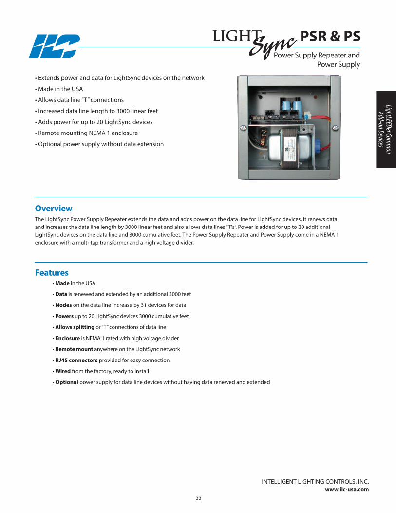
Overview The LightSync Power Supply Repeater extends the data and adds power on the data line for LightSync devices. It renews data and increases the data line length by 3000 Iinear feet and also allows data lines “T's”. Power is added for up to 20 additional LightSync devices on the data line and 3000 cumulative feet. The Power Supply Repeater and Power Supply come in a nEMA 1 enclosure with a multi-tap transformer and a high voltage divider.
• Extends power and data for LightSync devices on the network
• Made in the USA
• Allows data line “T” connections
• Increased data line length to 3000 linear feet
• Adds power for up to 20 LightSync devices
• Remote mounting nEMA 1 enclosure
• Optional power supply without data extension
• Made in the USA
• Data is renewed and extended by an additional 3000 feet
• Nodes on the data line increase by 31 devices for data
• Powers up to 20 LightSync devices 3000 cumulative feet
• Allows splitting or “T” connections of data line
• Enclosure is nEMA 1 rated with high voltage divider
• Remote mount anywhere on the LightSync network
• RJ45 connectors provided for easy connection
• Wired from the factory, ready to install
• Optional power supply for data line devices without having data renewed and extended
Features
InTELLIGEnT LIGHTInG COnTROLS, InC.www.ilc-usa.com
Power Supply Repeater andPower Supply
PSR & PS
33
LightLEEDer Comm
on Add-on Devices
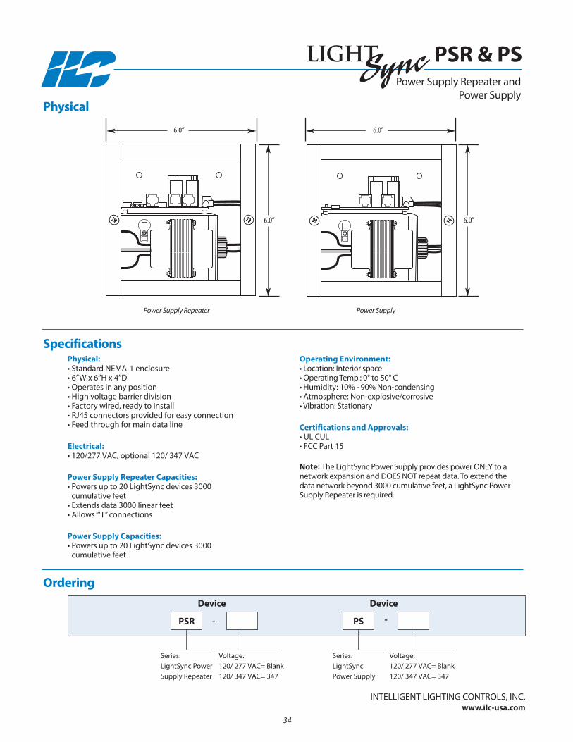
Physical:• Standard nEMA-1 enclosure• 6”W x 6”H x 4”D • Operates in any position• High voltage barrier division• Factory wired, ready to install• RJ45 connectors provided for easy connection• Feed through for main data line
Electrical:• 120/277 VAC, optional 120/ 347 VAC
Power Supply Repeater Capacities:• Powers up to 20 LightSync devices 3000
cumulative feet• Extends data 3000 linear feet• Allows “'T” connections
Power Supply Capacities:• Powers up to 20 LightSync devices 3000
cumulative feet
Operating Environment:• Location: Interior space• Operating Temp.: 0° to 50° C • Humidity: 10% - 90% non-condensing • Atmosphere: non-explosive/corrosive • Vibration: Stationary
Certifications and Approvals:• UL CUL• FCC Part 15
Note: The LightSync Power Supply provides power OnLy to a network expansion and DOES nOT repeat data. To extend thedata network beyond 3000 cumulative feet, a LightSync PowerSupply Repeater is required.
Physical
Specifications
Ordering
Series:LightSync PowerSupply Repeater
Voltage:120/ 277 VAC= Blank120/ 347 VAC= 347
Voltage:120/ 277 VAC= Blank120/ 347 VAC= 347
PSR - -
Device
Series:LightSync Power Supply
PS
Device
Power Supply Repeater andPower Supply
PSR & PS
Power Supply Repeater
6.0”
6.0”
Power Supply
6.0”
6.0”
InTELLIGEnT LIGHTInG COnTROLS, InC.www.ilc-usa.com
34
Expansion Processor
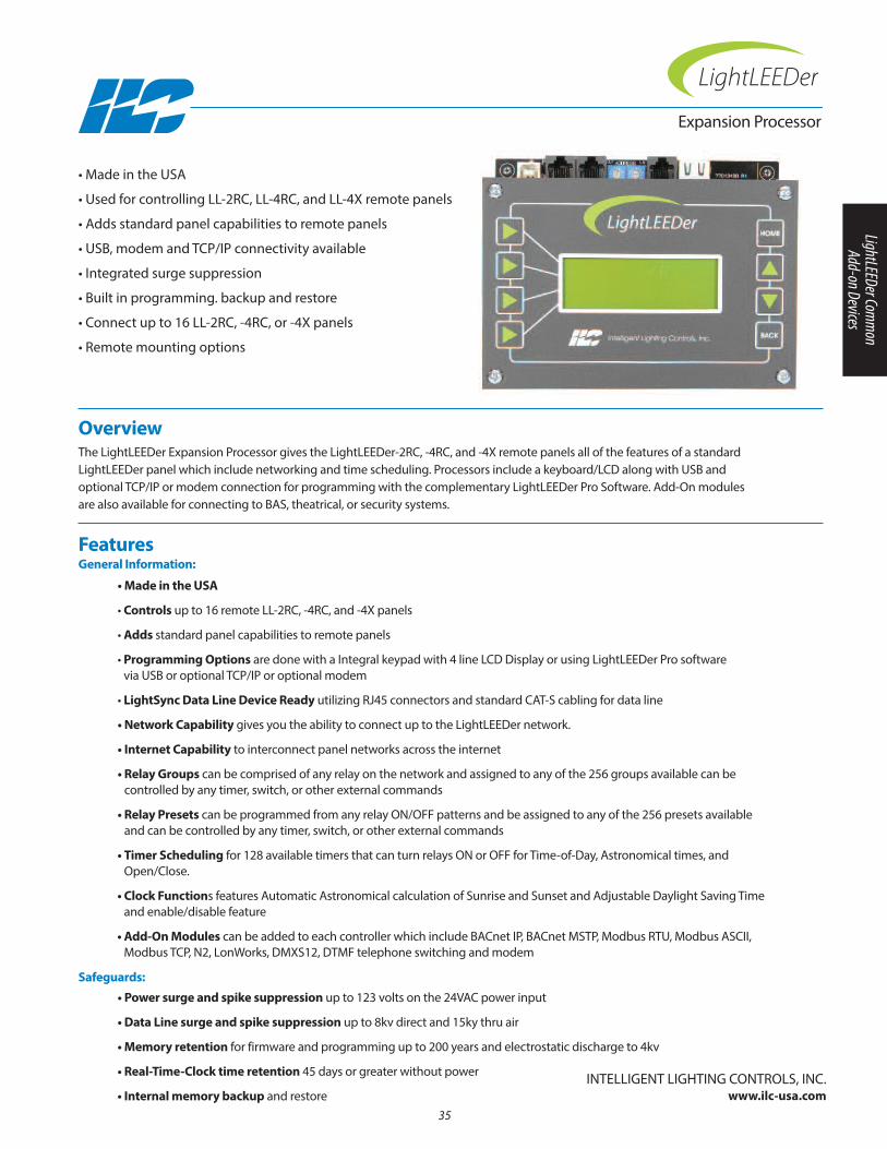
Overview The LightLEEDer Expansion Processor gives the LightLEEDer-2RC, -4RC, and -4X remote panels all of the features of a standardLightLEEDer panel which include networking and time scheduling. Processors include a keyboard/LCD along with USB and optional TCP/IP or modem connection for programming with the complementary LightLEEDer Pro Software. Add-On modules are also available for connecting to BAS, theatrical, or security systems.
• Made in the USA
• Used for controlling LL-2RC, LL-4RC, and LL-4X remote panels
• Adds standard panel capabilities to remote panels
• USB, modem and TCP/IP connectivity available
• Integrated surge suppression
• Built in programming. backup and restore
• Connect up to 16 LL-2RC, -4RC, or -4X panels
• Remote mounting options
Features General Information:
• Made in the USA
• Controls up to 16 remote LL-2RC, -4RC, and -4X panels
• Adds standard panel capabilities to remote panels
• Programming Options are done with a Integral keypad with 4 line LCD Display or using LightLEEDer Pro software via USB or optional TCP/IP or optional modem
• LightSync Data Line Device Ready utilizing RJ45 connectors and standard CAT-S cabling for data line
• Network Capability gives you the ability to connect up to the LightLEEDer network.
• Internet Capability to interconnect panel networks across the internet
• Relay Groups can be comprised of any relay on the network and assigned to any of the 256 groups available can be controlled by any timer, switch, or other external commands
• Relay Presets can be programmed from any relay On/OFF patterns and be assigned to any of the 256 presets availableand can be controlled by any timer, switch, or other external commands
• Timer Scheduling for 128 available timers that can turn relays On or OFF for Time-of-Day, Astronomical times, andOpen/Close.
• Clock Functions features Automatic Astronomical calculation of Sunrise and Sunset and Adjustable Daylight Saving Timeand enable/disable feature
• Add-On Modules can be added to each controller which include BACnet IP, BACnet MSTP, Modbus RTU, Modbus ASCII,Modbus TCP, n2, LonWorks, DMXS12, DTMF telephone switching and modem
• Power surge and spike suppression up to 123 volts on the 24VAC power input
• Data Line surge and spike suppression up to 8kv direct and 15ky thru air
• Memory retention for firmware and programming up to 200 years and electrostatic discharge to 4kv
• Real-Time-Clock time retention 45 days or greater without power
• Internal memory backup and restoreInTELLIGEnT LIGHTInG COnTROLS, InC.
www.ilc-usa.com35
Safeguards:
LightLEEDer Comm
on Add-on Devices
ALL OFFOFF ON
POWER
77013490 R1
ALL ON
Intelligent Lighting Controls, Inc.
77013497A97013497
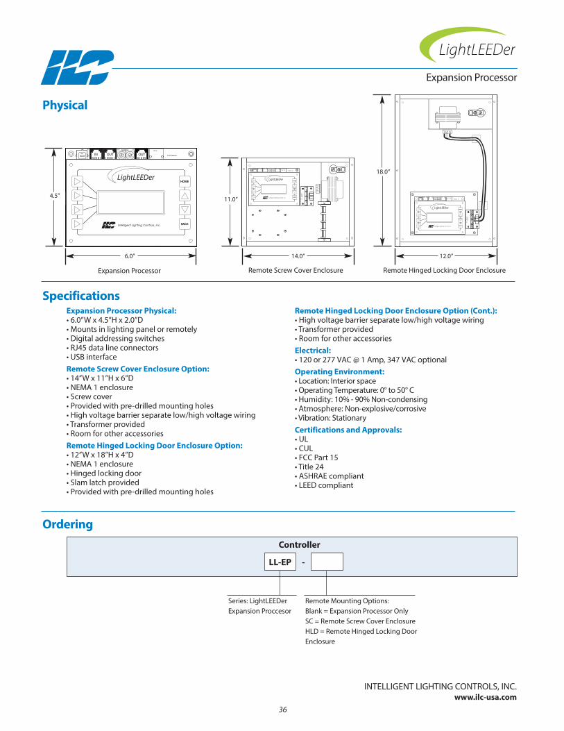
Expansion Processor Physical:• 6.0”W x 4.5”H x 2.0”D• Mounts in lighting panel or remotely• Digital addressing switches• RJ45 data line connectors• USB interfaceRemote Screw Cover Enclosure Option:• 14”W x 11”H x 6”D• nEMA 1 enclosure• Screw cover• Provided with pre-drilled mounting holes• High voltage barrier separate low/high voltage wiring• Transformer provided• Room for other accessoriesRemote Hinged Locking Door Enclosure Option:• 12”W x 18”H x 4”D• nEMA 1 enclosure• Hinged locking door• Slam latch provided• Provided with pre-drilled mounting holes
Remote Hinged Locking Door Enclosure Option (Cont.):• High voltage barrier separate low/high voltage wiring• Transformer provided• Room for other accessoriesElectrical:• 120 or 277 VAC @ 1 Amp, 347 VAC optionalOperating Environment:• Location: Interior space• Operating Temperature: 0° to 50° C • Humidity: 10% - 90% non-condensing • Atmosphere: non-explosive/corrosive • Vibration: StationaryCertifications and Approvals:• UL • CUL• FCC Part 15• Title 24• ASHRAE compliant• LEED compliant
Ordering
Expansion Processor
Controller
Physical
Specifications
InTELLIGEnT LIGHTInG COnTROLS, InC.www.ilc-usa.com
W1
1
ALL OFFALL ON
--
-
+
-
+
+
+
POWER
EP4 EP3 EP2 EP1
-+-+
-+
U17
J9
J3
J6
OUTIN OUT
ADDRESS
+
-
-
LSDMSD
IN LS
J5
OUT
+
98
CB
D
9876
45
A
3
7
4
6
53
2 F1E
12
AC
DB
EF
00
USB
TCP-IP
ONOFF
+
~
~
+
-
77013490 R1
+
TR1
TR2
J7
24VA
C C
T
-
-
C9
C8
C14
C15
U1
U19
U14
U18
Intelligent Lighting Controls, Inc.
36
Series: LightLEEDer Expansion Proccesor
LL-EP
Remote Mounting Options:Blank = Expansion Processor OnlySC = Remote Screw Cover EnclosureHLD = Remote Hinged Locking DoorEnclosure
-
4.5”
18.0”
6.0” 12.0”
Expansion Processor Remote Hinged Locking Door Enclosure
ALL OFFOFF ON
POWER
77013490 R1
ALL ON
Intelligent Lighting Controls, Inc.
77013497A97013497
11.0”
14.0”
Remote Screw Cover Enclosure

Section 3: Photo Sensors
• LightSync Photo Sensor
• LightSync Photo Sensor 4
• Hardwire Photo Sensor
37
Photo Sensors

38
InTELLIGEnT LIGHTInG COnTROLS, InC.www.ilc-usa.com
39
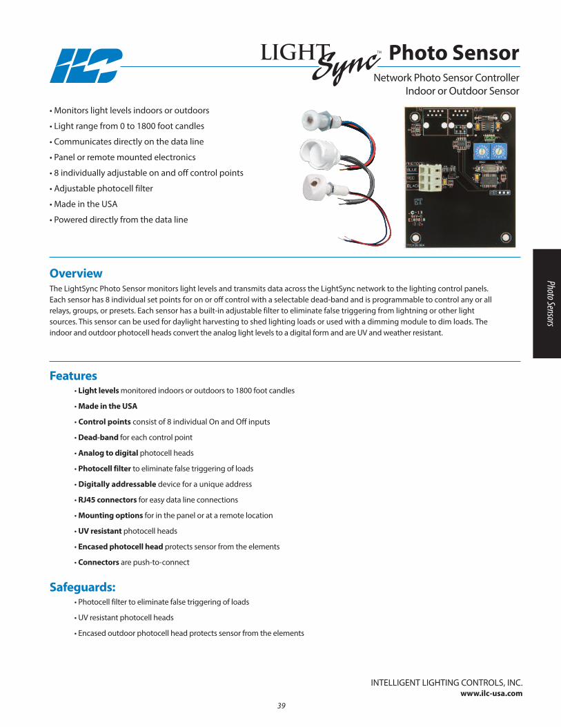
Overview The LightSync Photo Sensor monitors light levels and transmits data across the LightSync network to the lighting control panels.Each sensor has 8 individual set points for on or off control with a selectable dead-band and is programmable to control any or allrelays, groups, or presets. Each sensor has a built-in adjustable filter to eliminate false triggering from lightning or other lightsources. This sensor can be used for daylight harvesting to shed lighting loads or used with a dimming module to dim loads. Theindoor and outdoor photocell heads convert the analog light levels to a digital form and are UV and weather resistant.
• Monitors light levels indoors or outdoors
• Light range from 0 to 1800 foot candles
• Communicates directly on the data line
• Panel or remote mounted electronics
• 8 individually adjustable on and off control points
• Adjustable photocell filter
• Made in the USA
• Powered directly from the data line
• Light levels monitored indoors or outdoors to 1800 foot candles
• Made in the USA
• Control points consist of 8 individual On and Off inputs
• Dead-band for each control point
• Analog to digital photocell heads
• Photocell filter to eliminate false triggering of loads
• Digitally addressable device for a unique address
• RJ45 connectors for easy data line connections
• Mounting options for in the panel or at a remote location
• UV resistant photocell heads
• Encased photocell head protects sensor from the elements
• Connectors are push-to-connect
Features
• Photocell filter to eliminate false triggering of loads
• UV resistant photocell heads
• Encased outdoor photocell head protects sensor from the elements
Safeguards:
Photo SensorTM
network Photo Sensor ControllerIndoor or Outdoor Sensor
Photo Sensors
InTELLIGEnT LIGHTInG COnTROLS, InC.www.ilc-usa.com
40
BLUE
RED
BLACK
77013536A
BLUE
RED
BLACK
77013536A
B
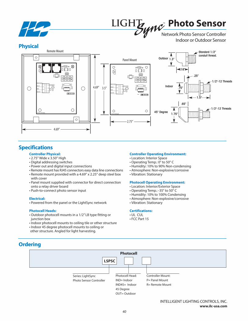
Panel Mount
2.75”
3.5”4.69”
4.69”
Photo SensorTM
network Photo Sensor ControllerIndoor or Outdoor Sensor
Ordering
Photocell Head:InD= IndoorInD45= Indoor45 DegreeOUT= Outdoor
Series: LightSync Photo Sensor Controller
LSPSC
Photocell
Controller Mount:P= Panel MountR= Remote Mount
Specifications
Physical
Controller Physical:• 2.75" Wide x 3.50" High• Digital addressing switches• Power out and digital input connections• Remote mount has RJ45 connectors easy data line connections• Remote mount provided with a 4.69" x 2.25" deep steel box
with cover• Panel mount supplied with connector for direct connection
onto a relay driver board• Push-to-connect photo sensor input
Electrical:• Powered from the panel or the LightSync network
Photocell Heads:• Outdoor photocell mounts in a 1/2” LB type fitting or
junction box • Indoor photocell mounts to ceiling tile or other structure• Indoor 45 degree photocell mounts to ceiling orother structure. Angled for light harvesting.
Controller Operating Environment:• Location: Interior Space• Operating Temp.: 0° to 50° C • Humidity: 10% to 90% non-condensing • Atmosphere: non-explosive/corrosive• Vibration: Stationary
Photocell Operating Environment:• Location: Interior/Exterior Space• Operating Temp.: -35° to 50° C • Humidity: 10% to 100% Condensing • Atmosphere: non-explosive/corrosive• Vibration: Stationary
Certifications:• UL CUL• FCC Part 15
Remote Mount
1.5”
.25”
.65”
.75”
1.75”
1.3”
1.18”
Indoor
45° Degree
Outdoor
Standard 1/2”conduit thread.
1/2"-12 Threads
1/2"-12 Threads
InTELLIGEnT LIGHTInG COnTROLS, InC.www.ilc-usa.com
41
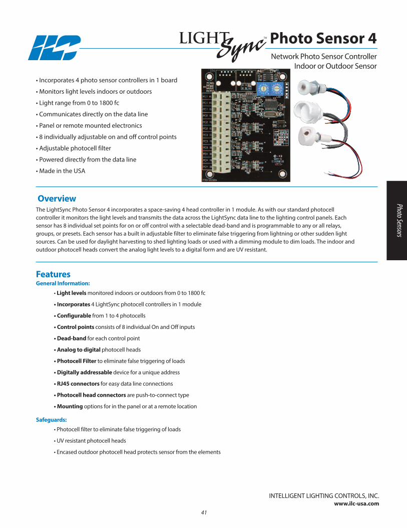
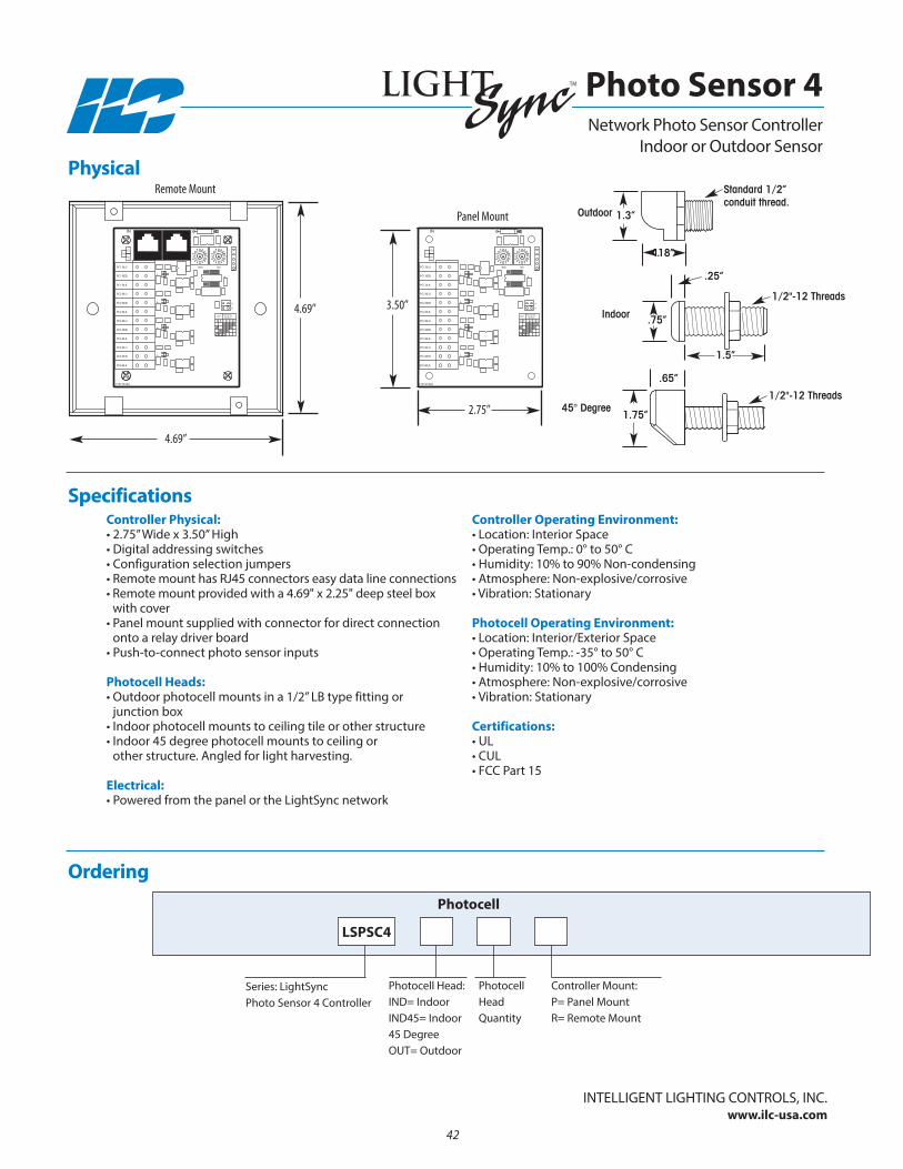
Overview The LightSync Photo Sensor 4 incorporates a space-saving 4 head controller in 1 module. As with our standard photocell controller it monitors the light levels and transmits the data across the LightSync data line to the lighting control panels. Each sensor has 8 individual set points for on or off control with a selectable dead-band and is programmable to any or all relays,groups, or presets. Each sensor has a built in adjustable filter to eliminate false triggering from lightning or other sudden lightsources. Can be used for daylight harvesting to shed lighting loads or used with a dimming module to dim loads. The indoor andoutdoor photocell heads convert the analog light levels to a digital form and are UV resistant.
• Incorporates 4 photo sensor controllers in 1 board
• Monitors light levels indoors or outdoors
• Light range from 0 to 1800 fc
• Communicates directly on the data line
• Panel or remote mounted electronics
• 8 individually adjustable on and off control points
• Adjustable photocell filter
• Powered directly from the data line
• Made in the USA
• Light levels monitored indoors or outdoors from 0 to 1800 fc
• Incorporates 4 LightSync photocell controllers in 1 module
• Configurable from 1 to 4 photocells
• Control points consists of 8 individual On and Off inputs
• Dead-band for each control point
• Analog to digital photocell heads
• Photocell Filter to eliminate false triggering of loads
• Digitally addressable device for a unique address
• RJ45 connectors for easy data line connections
• Photocell head connectors are push-to-connect type
• Mounting options for in the panel or at a remote location
• Photocell filter to eliminate false triggering of loads
• UV resistant photocell heads
• Encased outdoor photocell head protects sensor from the elements
FeaturesGeneral Information:
Safeguards:
Photo Sensor 4TM
network Photo Sensor ControllerIndoor or Outdoor Sensor
Photo Sensors
InTELLIGEnT LIGHTInG COnTROLS, InC.www.ilc-usa.com
42
IN
LSDMSD
77013532A
PC3 BLK
PC4 RED
PC2 BLU
PC2 BLK
PC3 RED
PC1 BLU
PC3 BLU
PC1 BLK
PC2 RED
PC1 RED
PC4 BLK
PC4 BLU
-
-
-
+
-
+
+
-
A B
+
-
+
B
JUMP
2 3 4
A
1
ENABLEDPHOTOCELL
R5
R4
R3
+
-
IN
LSDMSD
77013532A
PC3 BLK
PC4 RED
PC2 BLU
PC2 BLK
PC3 RED
PC1 BLU
PC3 BLU
PC1 BLK
PC2 RED
PC1 RED
PC4 BLK
PC4 BLU
-
-
-
+
-
+
+
-
A B
+
-
+
B
JUMP
2 3 4
A
1
ENABLEDPHOTOCELL
R5
R4
R3
+
-
2.75”
3.50”4.69”
4.69”
Photo Sensor 4TM
network Photo Sensor ControllerIndoor or Outdoor Sensor
Ordering
Photocell Head:InD= IndoorInD45= Indoor45 DegreeOUT= Outdoor
Series: LightSync Photo Sensor 4 Controller
LSPSC4
Photocell
Photocell Head Quantity
Controller Mount:P= Panel MountR= Remote Mount
Specifications
PhysicalRemote Mount
Panel Mount
Controller Physical:• 2.75” Wide x 3.50” High• Digital addressing switches• Configuration selection jumpers• Remote mount has RJ45 connectors easy data line connections• Remote mount provided with a 4.69" x 2.25" deep steel box
with cover• Panel mount supplied with connector for direct connection
onto a relay driver board• Push-to-connect photo sensor inputs
Photocell Heads:• Outdoor photocell mounts in a 1/2” LB type fitting or
junction box • Indoor photocell mounts to ceiling tile or other structure• Indoor 45 degree photocell mounts to ceiling or
other structure. Angled for light harvesting.
Electrical:• Powered from the panel or the LightSync network
Controller Operating Environment:• Location: Interior Space• Operating Temp.: 0° to 50° C • Humidity: 10% to 90% non-condensing • Atmosphere: non-explosive/corrosive• Vibration: Stationary
Photocell Operating Environment:• Location: Interior/Exterior Space• Operating Temp.: -35° to 50° C • Humidity: 10% to 100% Condensing • Atmosphere: non-explosive/corrosive• Vibration: Stationary
Certifications:• UL• CUL• FCC Part 15
1.5”
.25”
.65”
.75”
1.75”
1.3”
1.18”
Indoor
45° Degree
Outdoor
Standard 1/2”conduit thread.
1/2"-12 Threads
1/2"-12 Threads
• Light levels are monitored indoors or outdoors to 1000 foot candles
• Made in the USA
• Hardwire directly to panel inputs
• Adjustable for indoor and outdoor ranges
• Control points consist of 10 adjustable On and Off settings
• Analog to digital photocell heads
• Photocell filter to eliminate false triggering of loads
• Photocell head connectors are screw-to-connect type
• Mounts directly in the panel or in a remote location
• Remote controller can be mounted up to 5000 feet from lighting panel
• UV resistant photocell heads
• Encased photocell head protects sensor from the elements
FeaturesGeneral Information
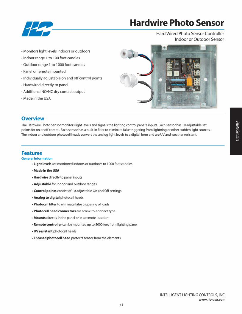
Overview The Hardwire Photo Sensor monitors light levels and signals the lighting control panel's inputs. Each sensor has 10 adjustable setpoints for on or off control. Each sensor has a built-in filter to eliminate false triggering from lightning or other sudden light sources.The indoor and outdoor photocell heads convert the analog light levels to a digital form and are UV and weather resistant.
InTELLIGEnT LIGHTInG COnTROLS, InC.www.ilc-usa.com
Hardwire Photo Sensor
• Monitors light levels indoors or outdoors
• Indoor range 1 to 100 foot candles
• Outdoor range 1 to 1000 foot candles
• Panel or remote mounted
• Individually adjustable on and off control points
• Hardwired directly to panel
• Additional nO/nC dry contact output
• Made in the USA
43
Hard Wired Photo Sensor ControllerIndoor or Outdoor Sensor
Photo Sensors
Ordering
Photocell Head:InD= IndoorOUT= Outdoor
Series: Hardwire Photocell Controller
PSC
Photocell
Controller Mount:P= Panel MountR= Remote Mount
Physical
Specifications
InTELLIGEnT LIGHTInG COnTROLS, InC.www.ilc-usa.com
Hardwire Photo SensorHard Wired Photo Sensor Controller
Indoor or Outdoor Sensor
44
Sensors
1.5”
.25”
.75”
1.3”
1.18”
Indoor
Outdoor
Standard 1/2” conduitthread.
1/2"-12 Threads
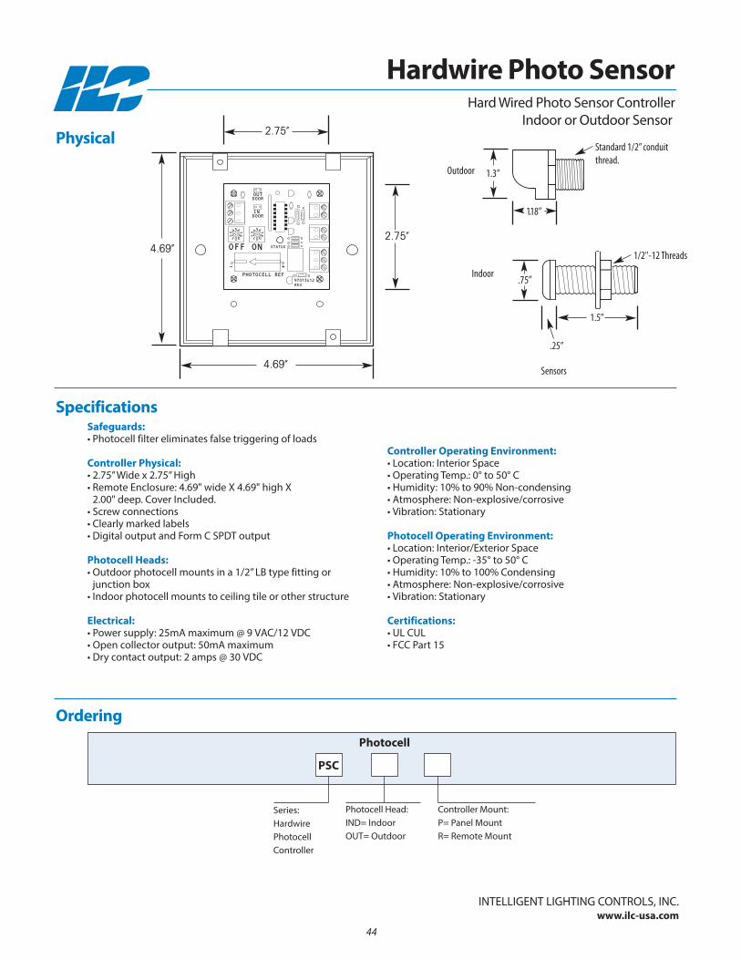
Safeguards:• Photocell filter eliminates false triggering of loads
Controller Physical:• 2.75” Wide x 2.75” High• Remote Enclosure: 4.69" wide X 4.69" high X
2.00" deep. Cover Included.• Screw connections• Clearly marked labels• Digital output and Form C SPDT output
Photocell Heads:• Outdoor photocell mounts in a 1/2” LB type fitting or
junction box • Indoor photocell mounts to ceiling tile or other structure
Electrical:• Power supply: 25mA maximum @ 9 VAC/12 VDC• Open collector output: 50mA maximum• Dry contact output: 2 amps @ 30 VDC
Controller Operating Environment:• Location: Interior Space• Operating Temp.: 0° to 50° C • Humidity: 10% to 90% non-condensing • Atmosphere: non-explosive/corrosive• Vibration: Stationary
Photocell Operating Environment:• Location: Interior/Exterior Space• Operating Temp.: -35° to 50° C • Humidity: 10% to 100% Condensing • Atmosphere: non-explosive/corrosive• Vibration: Stationary
Certifications:• UL CUL• FCC Part 15
PHOTOCELL REF
- +
STATUS
REV97013412
5432 109
87
6
DOOR
DOORIN
OUT
OFF ON
5432 109
87
6
4.69”
4.69”
2.75”
2.75”
Section 4: Occupancy Sensors
• Occupancy Sensors
• LightSync Occupancy Sensor Input Module
• LightSync Occupancy Sensor 8 Input Module
45
Occupancy Sensors

46

Overview ILC provides a full line of occupancy sensors to meet your facilities requirements. Sensors are available with passive infra red detection ordual-technology sensors that combine infrared detection along with sonic detection for a more robust sensor. Sensors are available inmany types including wall switches, ceiling mount, corner mount and surface mount. They are also available with a wide variety of lensesthat focus on the size of the room or hallway providing full coverage of detection.
Sensor Types
Contact ILC for ordering information
• Single or dual technology sensors
• Wall, ceiling, or surface mount
• Direct interface to lighting panels
• Line voltage or low voltage control
• Multiple coverage area patterns
InTELLIGEnT LIGHTInG COnTROLS, InC.www.ilc-usa.com
Occupancy Sensors
Ceiling-mount sensors are appropriate for large areasthat feature obstacles such aspartitions, in addition to nar-row spaces such as corridorsand warehouse aisles.
Wall switch (wall-box) sensors,are easy to install, and are appropriate for smaller, enclosed spaces, such as private offices with a clear line of sight between sensorand task area.
High wall and corner mountextended range sensors areexcellent for areas like class-rooms and gymnasiums.
47
Occupancy Sensors

48
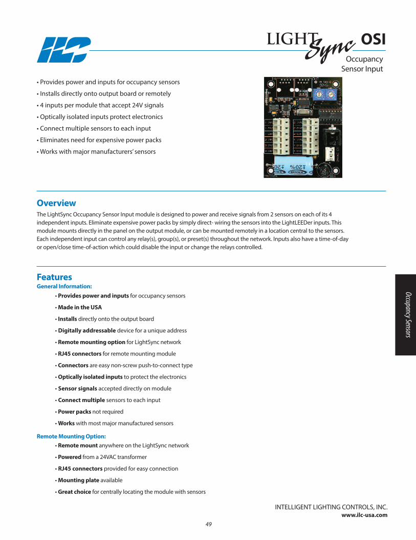
Overview The LightSync Occupancy Sensor Input module is designed to power and receive signals from 2 sensors on each of its 4 independent inputs. Eliminate expensive power packs by simply direct- wiring the sensors into the LightLEEDer inputs. This module mounts directly in the panel on the output module, or can be mounted remotely in a location central to the sensors. Each independent input can control any relay(s), group(s), or preset(s) throughout the network. Inputs also have a time-of-day or open/close time-of-action which could disable the input or change the relays controlled.
• Provides power and inputs for occupancy sensors
• Installs directly onto output board or remotely
• 4 inputs per module that accept 24V signals
• Optically isolated inputs protect electronics
• Connect multiple sensors to each input
• Eliminates need for expensive power packs
• Works with major manufacturers’ sensors
Occupancy Sensor Input
• Provides power and inputs for occupancy sensors
• Made in the USA
• Installs directly onto the output board
• Digitally addressable device for a unique address
• Remote mounting option for LightSync network
• RJ45 connectors for remote mounting module
• Connectors are easy non-screw push-to-connect type
• Optically isolated inputs to protect the electronics
• Sensor signals accepted directly on module
• Connect multiple sensors to each input
• Power packs not required
• Works with most major manufactured sensors
• Remote mount anywhere on the LightSync network
• Powered from a 24VAC transformer
• RJ45 connectors provided for easy connection
• Mounting plate available
• Great choice for centrally locating the module with sensors
FeaturesGeneral Information:
Remote Mounting Option:
InTELLIGEnT LIGHTInG COnTROLS, InC.www.ilc-usa.com
OSI
49
Occupancy Sensors

1 24VDC
1 INPUT
1 COM
3 INPUT
3 COM
3 24VDC
2 24VDC
2 INPUT
2 COM
4 INPUT
4 COM
4 24VDC
OUTIN
77013494A
24VAC CT
1 24VDC
1 INPUT
1 COM
3 INPUT
3 COM
3 24VDC
2 24VDC
2 INPUT
2 COM
4 INPUT
4 COM
4 24VDC
OUTIN
77013494A
24VAC CT
Remote Mount Panel Mount
3.5”
2.75”
3.5”
2.75”
Occupancy Sensor Input
OSI
Safeguards:• Optically isolated inputs protect electronicsPhysical:• 2.75” W x 3.5” H• Easy non-screw push-to-connect connectors• Digital addressing switches• RJ45 connectors for remote mounting option• Remote mount option includes mounting plate
and transformerElectrical:• Powered from panel transformer (remote option powered by
24VAC transformer).• 200mA @ 24VDC maximum draw per module
Operating Environment:• Location: Interior space• Operating Temp.: 0° to 50° C • Humidity: 10% - 90% non-condensing • Atmosphere: non-explosive/corrosive • Vibration: StationaryCertifications and Approvals:• FCC Part 15
Physical
Specifications
InTELLIGEnT LIGHTInG COnTROLS, InC.www.ilc-usa.com
Ordering
Series:LightSync Occupancy Sensor Input
LSOSI
Device
Mounting: P = PanelR = Remote
50

Overview The LightSync Occupancy Sensor 8 Input module is designed to power and receive signals from multiple sensors on each of its 8 independent inputs. Eliminate expensive power packs by simply direct- wiring the sensors into the LightLEEDer inputs. This module mounts directly in the panel on the output module, or can be mounted remotely in a location central to the sensors. Each independent input can control any relay(s), group(s), or preset(s) throughout the network. Inputs also have a time-of-day or open/close time-of-action which could disable the input or change the relays controlled.
• Provides power and inputs for occupancy sensors
• Installs directly onto output board or remotely
• 8 inputs per module that accept 24V signals
• Optically isolated inputs protect electronics
• Connect multiple sensors to each input
• Eliminates need for expensive power packs
• Works with major manufacturers’ sensors
• Made in the USA
Occupancy Sensor 8 Input Module
• Provides power and inputs for occupancy sensors
• Made in the USA
• Installs directly onto the output board
• Digitally addressable device for a unique address
• Remote mounting option for LightSync network
• RJ45 connectors for remote mounting module
• Connectors are easy non-screw push-to-connect type
• Optically isolated inputs to protect the electronics
• Sensor signals accepted directly on module
• Connect master and slave sensors to each input
• Works with most major manufactured sensors
• Remote mount anywhere on the LightSync network
• Powered from a 120/277VAC power supply
• RJ45 connectors provided for easy connection
• Great choice for centrally locating the module with sensors
FeaturesGeneral Information
Remote Mounting Option
InTELLIGEnT LIGHTInG COnTROLS, InC.www.ilc-usa.com
OS8I
51
Occupancy Sensors
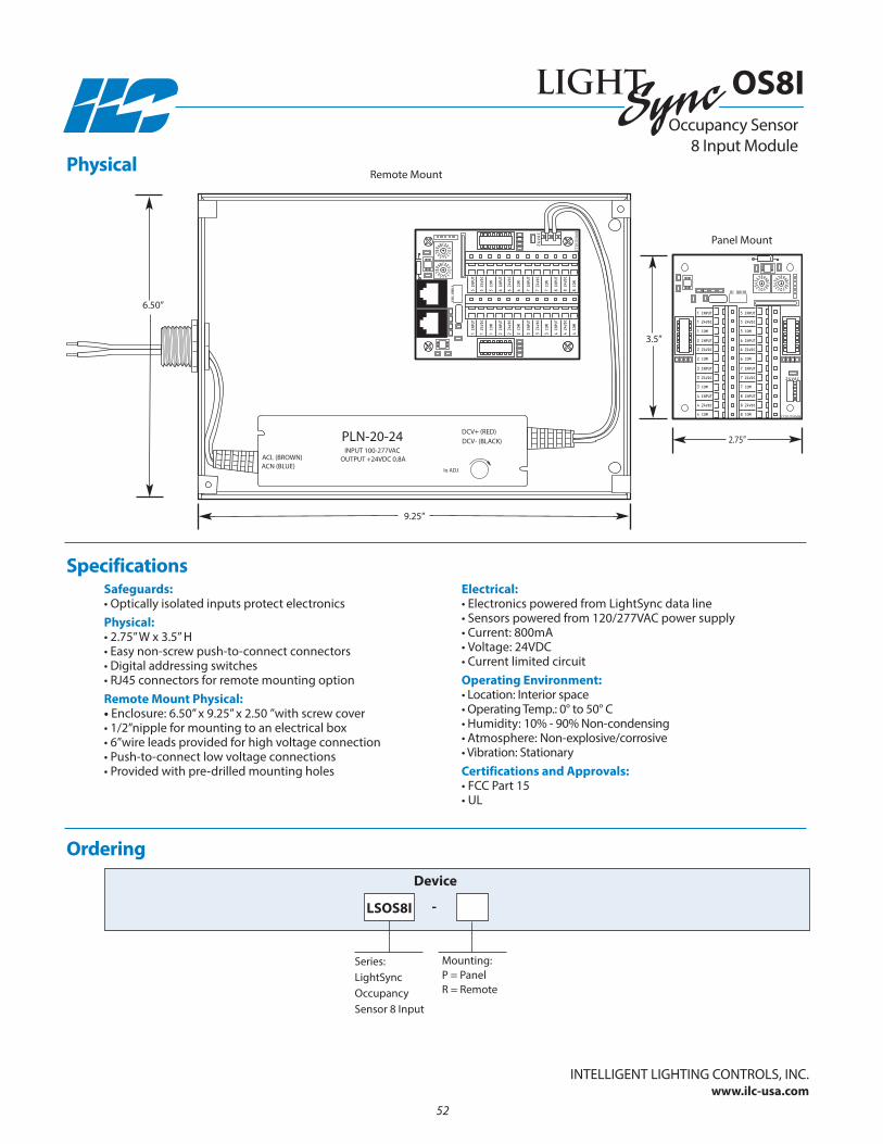
1 24VDC
1 INPUT
1 COM
2 24VDC
2 INPUT
2 COM
3 INPUT
3 COM
3 24VDC
4 INPUT
4 COM
4 24VDC
5 24VDC
5 INPUT
5 COM
6 24VDC
6 INPUT
6 COM
7 INPUT
7 COM
7 24VDC
8 INPUT
8 COM
8 24VDC
77013506B
24VAC
1 24VDC
1 INPUT
1 COM
2 24VDC
2 INPUT
2 COM
3 INPUT
3 COM
3 24VDC
4 INPUT
4 COM
4 24VDC
5 24VDC
5 INPUT
5 COM
6 24VDC
6 INPUT
6 COM
7 INPUT
7 COM
7 24VDC
8 INPUT
8 COM
8 24VDC
77013506B
24VAC
Panel Mount
6.50”
9.25”
3.5”
2.75”
Occupancy Sensor 8 Input Module
OS8I
Safeguards:• Optically isolated inputs protect electronicsPhysical:• 2.75” W x 3.5” H• Easy non-screw push-to-connect connectors• Digital addressing switches• RJ45 connectors for remote mounting optionRemote Mount Physical:• Enclosure: 6.50” x 9.25” x 2.50 ”with screw cover• 1/2”nipple for mounting to an electrical box• 6”wire leads provided for high voltage connection• Push-to-connect low voltage connections• Provided with pre-drilled mounting holes
Electrical:• Electronics powered from LightSync data line• Sensors powered from 120/277VAC power supply• Current: 800mA • Voltage: 24VDC• Current limited circuitOperating Environment:• Location: Interior space• Operating Temp.: 0° to 50° C • Humidity: 10% - 90% non-condensing • Atmosphere: non-explosive/corrosive • Vibration: StationaryCertifications and Approvals:• FCC Part 15• UL
Physical
Specifications
InTELLIGEnT LIGHTInG COnTROLS, InC.www.ilc-usa.com
Ordering
Series:LightSync Occupancy Sensor 8 Input
LSOS8I
Device
Mounting: P = PanelR = Remote
52
-
Remote Mount
Section 5: CAT5 Switches and Devices
• LightSync G2 Data Line Switch• LightSync Classic Data Line Switch• LightSync Touch Screen Station• LightSync Key Switch
• LightSync Disable Key Switch• LightSync Touch Switch• LightSync Slide Switch
53
CAT5 Switches and Devices

54
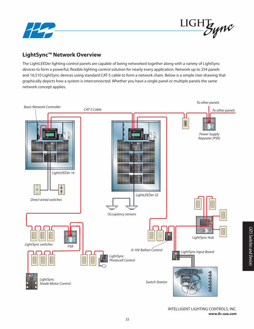
LightSync™ Network OverviewThe LightLEEDer lighting control panels are capable of being networked together along with a variety of LightSync devices to form a powerful, flexible lighting control solution for nearly every application. network up to 254 panels and 16,510 LightSync devices using standard CAT-5 cable to form a network chain. Below is a simple riser drawing thatgraphically depicts how a system is interconnected. Whether you have a single panel or multiple panels the same network concept applies.
1 ON
1 PILOT
1 OFF
1 COM
3 ON
3 OFF
3 COM
3 PILOT
2 ON
2 PILOT
2 OFF
2 COM
4 ON
4 OFF
4 COM
EXT +V
EXTCOM
4 PILOT
OUTIN
77013485A
MOTOR 1
MOTOR 2
MOTOR 3
MOTOR 4
12VAC
12VAC
CT
77013442 REV A97013442 REV
IN
1
2
3
4
OUT 77013489B
MTR1-LS1 LS1BYPASS
LS2BYPASS
LS1BYPASS
IN-1
IN-2
OUT-A
OUT-B
IN-1
IN-2
OUT-A
OUT-B
IN-1
IN-2
OUT-A
OUT-B
IN-1
IN-2
OUT-A
OUT-B
LS2BYPASS
LS1BYPASS
LS2BYPASS
LS1BYPASS
LS2BYPASS
MTR1-LSC
MTR1-LS2
MTR2-LS1
MTR2-LSC
MTR2-LS2
MTR3-LS1
MTR3-LSC
MTR3-LS2
MTR4-LS1
MTR4-LSC
MTR4-LS2
OUTIN
12VAC
12VAC
CT
24VAC CT
1 ON
1 PILOT
1 OFF
1 COM
3 ON
3 OFF
3 COM
3 PILOT
2 ON
2 PILOT
2 OFF
2 COM
4 ON
4 OFF
4 COM
EXT +V
EXTCOM
4 PILOT
POWER
24VAC CT
24VAC CT
77013488A
97013488
POWER
24VAC CT
24VAC CT
77013488A
97013488
1 ON
1 PILOT
1 OFF
1 COM
3 ON
3 OFF
3 COM
3 PILOT
2 ON
2 PILOT
2 OFF
2 COM
4 ON
4 OFF
4 COM
EXT +V
EXTCOM
4 PILOT
24VAC CT
24VAC CT
77013488A
97013488
POWER
24VAC CT
24VAC CT
77013488A
97013488
POWER
24VAC CT
24VAC CT
77013488A
97013488
POWER
24VAC CT
24VAC CT
77013488A
97013488
InTELLIGEnT LIGHTInG COnTROLS, InC.www.ilc-usa.com
Basic Network Controller
LightLEEDer 16
CAT-5 Cable
Direct wired switches
Occupancy sensors
LightLEEDer 32
Power Supply Repeater (PSR)
PSR
LightSync Hub
Switch Station
0-10V Ballast Control
LightSyncPhotocell Control
LightSync switches
LightSync Input Board
LightSyncShade Motor Control
To other panels
To other panels
55
CAT5 Switches and Devices

56
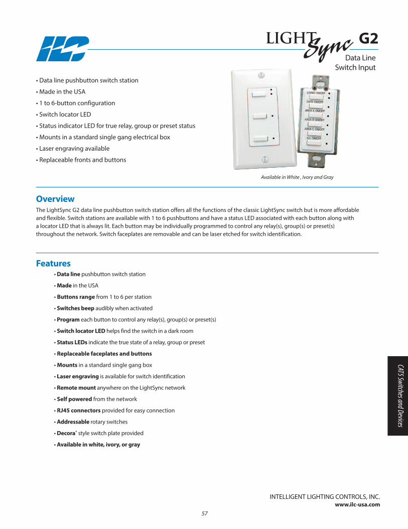
Overview The LightSync G2 data line pushbutton switch station offers all the functions of the classic LightSync switch but is more affordableand flexible. Switch stations are available with 1 to 6 pushbuttons and have a status LED associated with each button along with a locator LED that is always lit. Each button may be individually programmed to control any relay(s), group(s) or preset(s) throughout the network. Switch faceplates are removable and can be laser etched for switch identification.
• Data line pushbutton switch station
• Made in the USA
• 1 to 6-button configuration
• Switch locator LED
• Status indicator LED for true relay, group or preset status
• Mounts in a standard single gang electrical box
• Laser engraving available
• Replaceable fronts and buttons
• Data line pushbutton switch station
• Made in the USA
• Buttons range from 1 to 6 per station
• Switches beep audibly when activated
• Program each button to control any relay(s), group(s) or preset(s)
• Switch locator LED helps find the switch in a dark room
• Status LEDs indicate the true state of a relay, group or preset
• Replaceable faceplates and buttons
• Mounts in a standard single gang box
• Laser engraving is available for switch identification
• Remote mount anywhere on the LightSync network
• Self powered from the network
• RJ45 connectors provided for easy connection
• Addressable rotary switches
• Decora® style switch plate provided
• Available in white, ivory, or gray
Features
InTELLIGEnT LIGHTInG COnTROLS, InC.www.ilc-usa.com
Available in White , Ivory and Gray
Data Line Switch Input
G2
57
CAT5 Switches and Devices
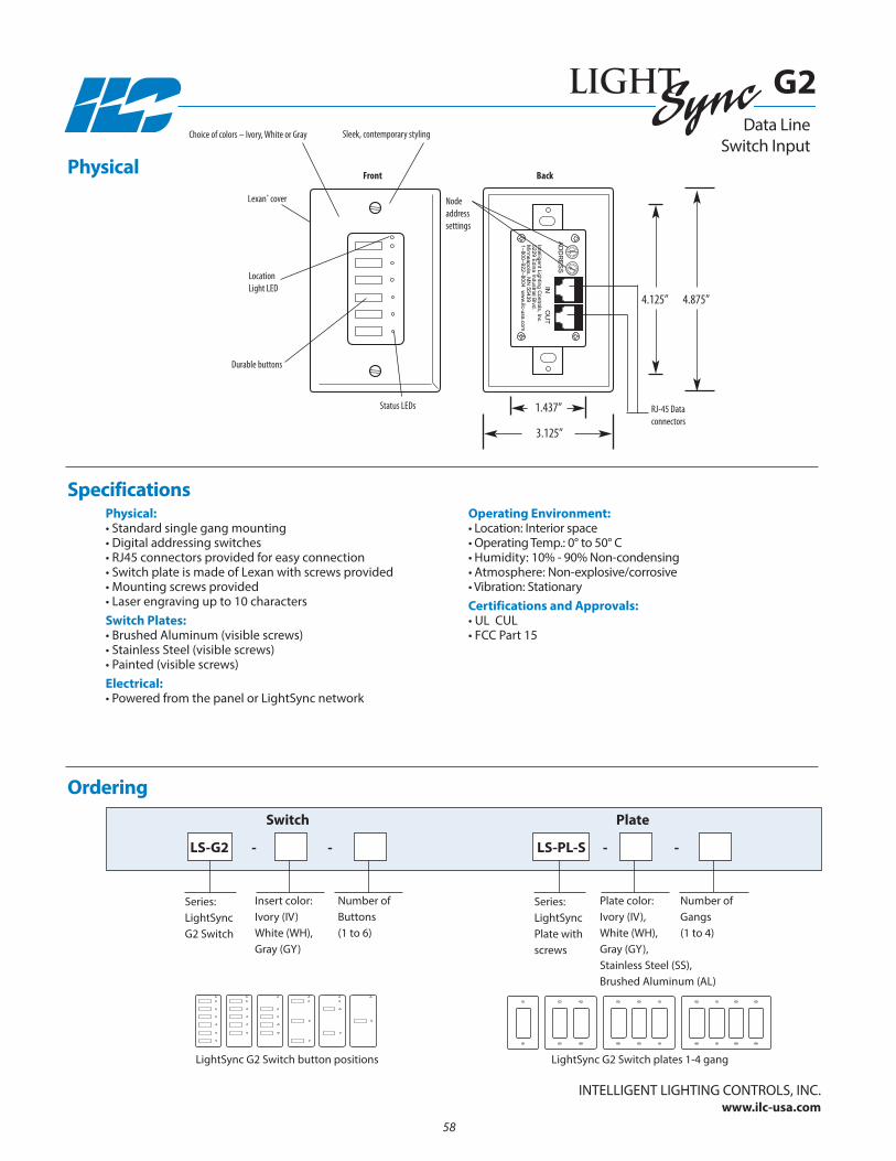
Data Line Switch Input
G2
Physical:• Standard single gang mounting• Digital addressing switches• RJ45 connectors provided for easy connection• Switch plate is made of Lexan with screws provided• Mounting screws provided• Laser engraving up to 10 characters Switch Plates:• Brushed Aluminum (visible screws) • Stainless Steel (visible screws)• Painted (visible screws)Electrical:• Powered from the panel or LightSync network
Operating Environment:• Location: Interior space• Operating Temp.: 0° to 50° C • Humidity: 10% - 90% non-condensing • Atmosphere: non-explosive/corrosive • Vibration: StationaryCertifications and Approvals:• UL CUL• FCC Part 15
Physical
Specifications
Ordering
Insert color: Ivory (IV)White (WH), Gray (Gy)
Series:LightSyncG2 Switch
LS-G2 - - - -
Switch
number of Buttons (1 to 6)
Plate color: Ivory (IV), White (WH), Gray (Gy),Stainless Steel (SS),Brushed Aluminum (AL)
Series:LightSyncPlate withscrews
LS-PL-S
Plate
number of Gangs (1 to 4)
3.125”
4.875”
Sleek, contemporary stylingChoice of colors – Ivory, White or Gray
Durable buttons
Status LEDs
LocationLight LED
RJ-45 Data connectors
Node addresssettings
Lexan® cover
Front Back
1.437”
4.125”
LightSync G2 Switch button positions LightSync G2 Switch plates 1-4 gang
InTELLIGEnT LIGHTInG COnTROLS, InC.www.ilc-usa.com
58
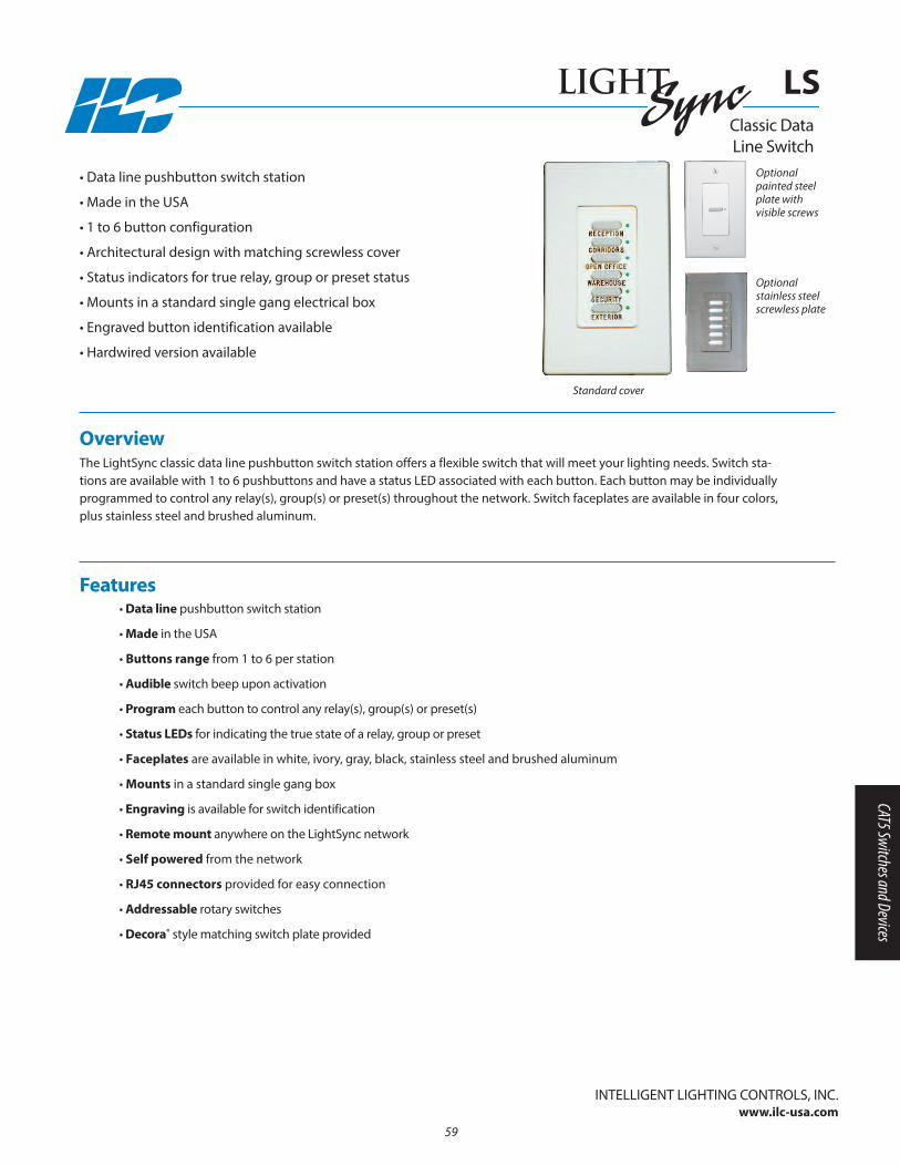
Overview The LightSync classic data line pushbutton switch station offers a flexible switch that will meet your lighting needs. Switch sta-tions are available with 1 to 6 pushbuttons and have a status LED associated with each button. Each button may be individuallyprogrammed to control any relay(s), group(s) or preset(s) throughout the network. Switch faceplates are available in four colors,plus stainless steel and brushed aluminum.
• Data line pushbutton switch station
• Made in the USA
• 1 to 6 button configuration
• Architectural design with matching screwless cover
• Status indicators for true relay, group or preset status
• Mounts in a standard single gang electrical box
• Engraved button identification available
• Hardwired version available
• Data line pushbutton switch station
• Made in the USA
• Buttons range from 1 to 6 per station
• Audible switch beep upon activation
• Program each button to control any relay(s), group(s) or preset(s)
• Status LEDs for indicating the true state of a relay, group or preset
• Faceplates are available in white, ivory, gray, black, stainless steel and brushed aluminum
• Mounts in a standard single gang box
• Engraving is available for switch identification
• Remote mount anywhere on the LightSync network
• Self powered from the network
• RJ45 connectors provided for easy connection
• Addressable rotary switches
• Decora® style matching switch plate provided
Features
InTELLIGEnT LIGHTInG COnTROLS, InC.www.ilc-usa.com
Optionalpainted steelplate with visible screws
Standard cover
Optional stainless steel screwless plate
Classic Data Line Switch
LS
59
CAT5 Switches and Devices
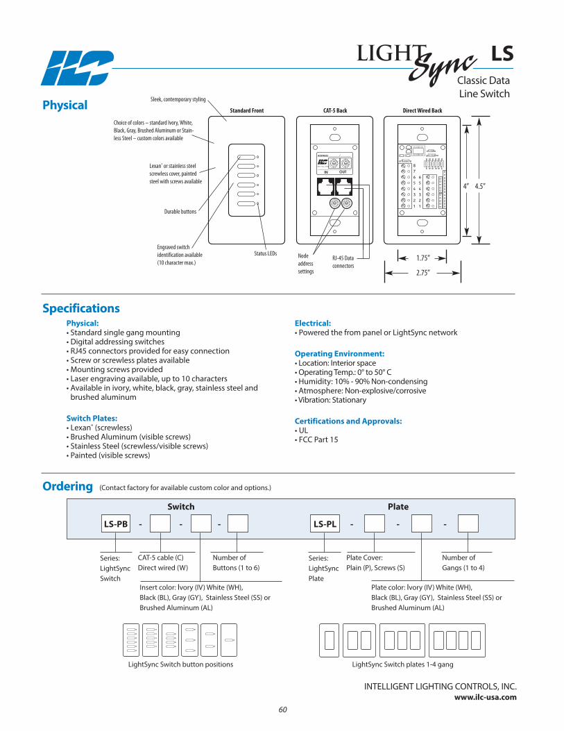
Physical:• Standard single gang mounting• Digital addressing switches• RJ45 connectors provided for easy connection• Screw or screwless plates available• Mounting screws provided• Laser engraving available, up to 10 characters• Available in ivory, white, black, gray, stainless steel and
brushed aluminum
Switch Plates:• Lexan® (screwless) • Brushed Aluminum (visible screws) • Stainless Steel (screwless/visible screws)• Painted (visible screws)
Electrical:• Powered the from panel or LightSync network
Operating Environment:• Location: Interior space• Operating Temp.: 0° to 50° C • Humidity: 10% - 90% non-condensing • Atmosphere: non-explosive/corrosive • Vibration: Stationary
Certifications and Approvals:• UL • FCC Part 15
Physical
Specifications
Ordering
Insert color: Ivory (IV) White (WH), Black (BL), Gray (Gy), Stainless Steel (SS) orBrushed Aluminum (AL)
Plate color: Ivory (IV) White (WH), Black (BL), Gray (Gy), Stainless Steel (SS) orBrushed Aluminum (AL)
Series:LightSyncSwitch
LS-PB
Switch
CAT-5 cable (C)Direct wired (W)
number of Buttons (1 to 6)
Series:LightSyncPlate
LS-PL
Plate
Plate Cover: Plain (P), Screws (S)
number of Gangs (1 to 4)
LightSync Switch button positions LightSync Switch plates 1-4 gang
800-922-8004
IN
ADDRESS
OUT
2.75”
4.5”
Sleek, contemporary styling
Choice of colors – standard Ivory, White,Black, Gray, Brushed Aluminum or Stain-less Steel – custom colors available
Engraved switch identification available(10 character max.)
Durable buttons
Status LEDsRJ-45 Data connectors
Node addresssettings
Lexan® or stainless steelscrewless cover, paintedsteel with screws available
Standard Front CAT-5 Back Direct Wired Back
1.75”
4”
(Contact factory for available custom color and options.)
Classic Data Line Switch
LS
InTELLIGEnT LIGHTInG COnTROLS, InC.www.ilc-usa.com
- - - - - -
60
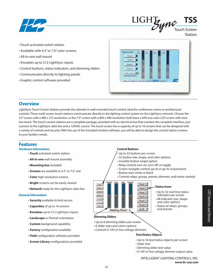
61
• Touch activated switch station
• AII-in-one wall mount assembly
• Mounting box included
• Screens are available in 4.3" or 7.0" size
• Color high resolution screens
• Bright screens can be easily viewed
• Network ready for the LightSync data line
• Security available to limit access
• Capacities of up to 16 screens
• Emulates up to 512 LightSync inputs
• Landscape or Portrait orientation
• Custom background capability
• Factory configuration available
• Field configuration software provided
• Screen Library configurations provided
Overview LightSync Touch Screen Stations provide the ultimate in wall-mounted touch control, ideal for conference rooms or architectural controls. These multi-screen touch stations communicate directly to the lighting control system on the LightSync network. Choose the4.3” screen with a 480 x 272 resolution, or the 7.0" screen with a 800 x 480 resolution; both have a 65K true color LCD screen with resis-tive touch. The touch control stations are a complete package, provided with an electrical box that contains the complete interface, justconnect to the LightSync data line and a 120VAC source. The touch screen has a capacity of up to 16 screens that can be designed witha variety of controls and security. With the use of the included intuitive software, you will be able to design the control station screensto your facility's needs.
• Touch activated switch station
• Available with 4.3” or 7.0” color screens
• All-in-one wall mount
• Emulates up to 512 LightSync inputs
• Control buttons, status indicators, and dimming sliders
• Communicates directly to lighting panels
• Graphic control software provided
InTELLIGEnT LIGHTInG COnTROLS, InC.www.ilc-usa.com
FeaturesHardware Information:
General Information:
• Up to 32 buttons per screen• 32 button size, shape, and color options• Invisible button target option• Relay control; turn on, turn off, or toggle• Screen navigate control; go-to or go-to w/password• Button text; white or black• Controls relays, groups, presets, dimmers, and motor controls
Control Buttons
• Up to 32 real time statusindicators per screen
• 48 indicator size, shape,and color options
• Status of relays, groups,and presets
Status Icons
• Up to 8 dimming sliders per screen• 6 slider sizes and colors options• Controls 0-10V or line voltage dimmers
Dimming Sliders
• Up to 16 text/status objects per screen• Static text• Dimming slider text value• 0-10V or line voltage dimmer output value
Text/Status Objects
TSSTouch Screen
Station
CAT5 Switches and Devices
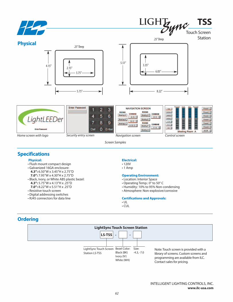
InTELLIGEnT LIGHTInG COnTROLS, InC.www.ilc-usa.com
62
Ordering
Size:-4.3, -7.0
LightSync Touch ScreenStation LS-TSS
LightSync Touch Screen Station
Bezel Color:Black (BK)Ivory (IV)White (WH)
Physical
Specifications
TSS
LS-TSS --
note: Touch screen is provided with alibrary of screens. Custom screens andprogramming are available from ILC.Contact sales for pricing.
4.15”
5.75”
3.75”
5.51”
.25” Deep
.25” Deep
2.15”
8.22”
6.05”
3.35”
Physical:• Flush mount compact design• Galvanized 16GA enclosure:
4.3”: 6.50”W x 3.45”H x 2.75”D7.0”: 7.95"W x 4.30"H x 2.75"D
• Black, Ivory, or White ABS plastic bezel:4.3”: 5.75”W x 4.13”H x .25”D7.0”: 8.22"W x 5.51"H x .25"D
• Resistive touch screen• Digital addressing switches• RJ45 connectors for data line
Electrical:• 120V• 1 Amp
Operating Environment:• Location: Interior Space• Operating Temp.: 0° to 50° C • Humidity: 10% to 95% non-condensing • Atmosphere: non-explosive/corrosive
Certifications and Approvals:• UL• CUL
Home screen with logo Security entry screen
Screen Samples
Navigation screen Control screen
Touch Screen Station
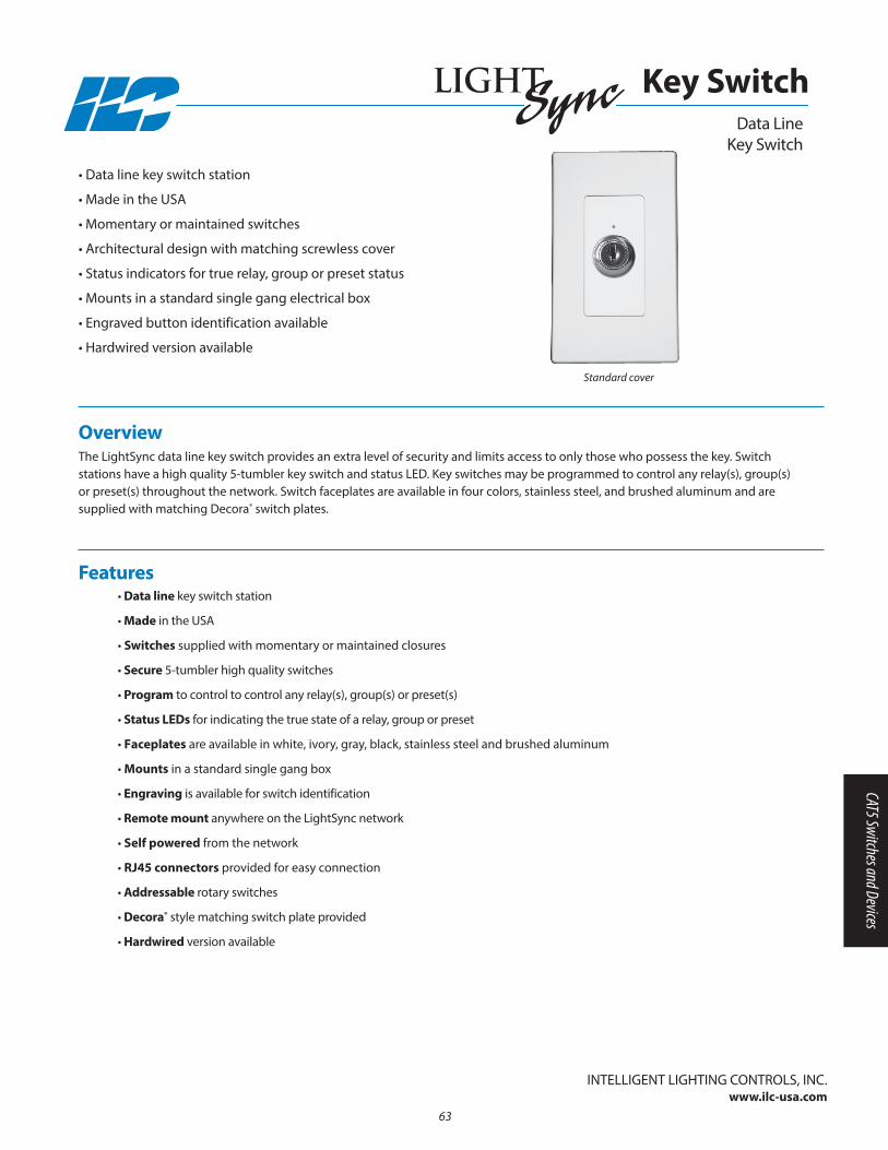
Overview The LightSync data line key switch provides an extra level of security and limits access to only those who possess the key. Switchstations have a high quality 5-tumbler key switch and status LED. Key switches may be programmed to control any relay(s), group(s)or preset(s) throughout the network. Switch faceplates are available in four colors, stainless steel, and brushed aluminum and aresupplied with matching Decora® switch plates.
• Data line key switch station
• Made in the USA
• Momentary or maintained switches
• Architectural design with matching screwless cover
• Status indicators for true relay, group or preset status
• Mounts in a standard single gang electrical box
• Engraved button identification available
• Hardwired version available
• Data line key switch station
• Made in the USA
• Switches supplied with momentary or maintained closures
• Secure 5-tumbler high quality switches
• Program to control to control any relay(s), group(s) or preset(s)
• Status LEDs for indicating the true state of a relay, group or preset
• Faceplates are available in white, ivory, gray, black, stainless steel and brushed aluminum
• Mounts in a standard single gang box
• Engraving is available for switch identification
• Remote mount anywhere on the LightSync network
• Self powered from the network
• RJ45 connectors provided for easy connection
• Addressable rotary switches
• Decora® style matching switch plate provided
• Hardwired version available
Features
InTELLIGEnT LIGHTInG COnTROLS, InC.www.ilc-usa.com
Data Line Key Switch
Key Switch
Standard cover
63
CAT5 Switches and Devices
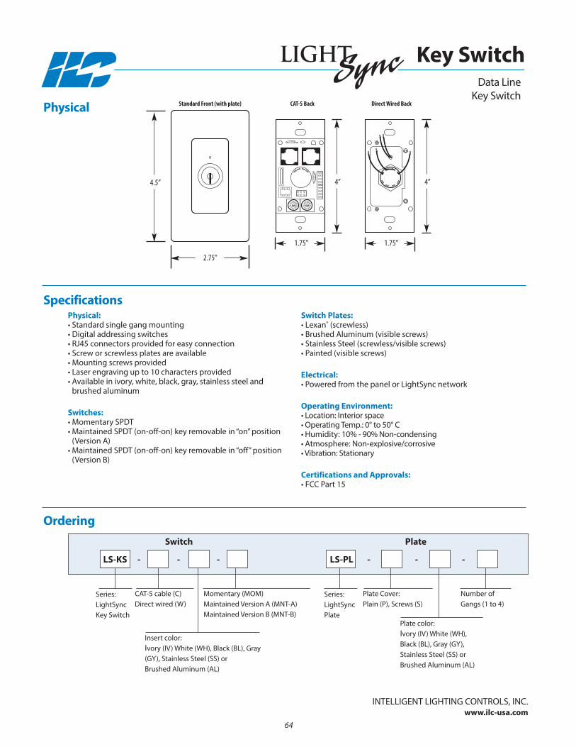
Physical:• Standard single gang mounting• Digital addressing switches• RJ45 connectors provided for easy connection• Screw or screwless plates are available• Mounting screws provided• Laser engraving up to 10 characters provided• Available in ivory, white, black, gray, stainless steel and
brushed aluminum
Switches:• Momentary SPDT • Maintained SPDT (on-off-on) key removable in “on” position
(Version A)• Maintained SPDT (on-off-on) key removable in “off” position
(Version B)
Switch Plates:• Lexan® (screwless) • Brushed Aluminum (visible screws) • Stainless Steel (screwless/visible screws)• Painted (visible screws)
Electrical:• Powered from the panel or LightSync network
Operating Environment:• Location: Interior space• Operating Temp.: 0° to 50° C • Humidity: 10% - 90% non-condensing • Atmosphere: non-explosive/corrosive • Vibration: Stationary
Certifications and Approvals:• FCC Part 15
Physical
Specifications
Ordering
Insert color: Ivory (IV) White (WH), Black (BL), Gray(Gy), Stainless Steel (SS) orBrushed Aluminum (AL)
Plate color: Ivory (IV) White (WH), Black (BL), Gray (Gy), Stainless Steel (SS) orBrushed Aluminum (AL)
Series:LightSyncKey Switch
LS-KS - - - - - -
Switch
CAT-5 cable (C)Direct wired (W)
Momentary (MOM)Maintained Version A (MnT-A)Maintained Version B (MnT-B)
Series:LightSyncPlate
LS-PL
Plate
Plate Cover: Plain (P), Screws (S)
number of Gangs (1 to 4)
Data Line Key Switch
Key Switch
Standard Front (with plate) CAT-5 Back Direct Wired Back
1.75”1.75”
4”4”
2.75”
4.5”
InTELLIGEnT LIGHTInG COnTROLS, InC.www.ilc-usa.com
64

Overview The LightSync disable key switch provides an extra level of security by disabling all Lightsync devices down from the disable switch.Ideal for areas with switches that require control functions to be limited or locked out. Switch stations have a high quality 5-tumblerkey switch and status LED. Faceplates are available in four colors and are supplied with matching switch plates..
• Disables LightSync devices
• Made in the USA
• Maintained switch with removable key
• Architectural design with matching screwless cover
• Status indicator for disable state
• Mounts in a standard single gang electrical box
• Engraved button identification available
• Disables LightSync devices on the data line
• Feed-through allows for normal data line communication
• Made in the USA
• Key Switch maintained type with removable key
• Secure 5-tumbler high quality switches
• Status LED indicates disable state
• Faceplates are available in white, ivory, gray, black, stainless steel and brushed aluminum
• Mounts in a standard single gang box
• Engraving is available for switch identification
• Mount anywhere on the LightSync network
• Self-powered from the network
• RJ45 connectors provided for easy connection
• Decora® matching switch plate provided
Features
InTELLIGEnT LIGHTInG COnTROLS, InC.www.ilc-usa.com
Data Line Disable Key Switch
Disable Key Switch
65
CAT5 Switches and Devices

Physical:• Standard single gang mounting• Data in, data out, and data disable out ports• RJ45 connectors provided for easy connection• Screw or screwless plates available• Mounting screws provided• Laser engraving up to 10 characters available• Available in ivory, white, black, gray, stainless steel and
brushed aluminum
Switches:• Maintained SPST key removable in “on” or “off”
position
Switch Plates:• Lexan® (screwless) • Brushed Aluminum (visible screws) • Stainless Steel (screwless/visible screws)• Painted (visible screws)
Electrical:• Powered from the panel or LightSync network
Operating Environment:• Location: Interior space• Operating Temp.: 0° to 50° C • Humidity: 10% - 90% non-condensing • Atmosphere: non-explosive/corrosive • Vibration: Stationary
Certifications and Approvals:• UL• FCC Part 15
Physical
Specifications
Ordering
Plate color: Ivory (IV) White (WH), Black (BL), Gray (Gy), Stainless Steel (SS) orBrushed Aluminum (AL)
LS-DKS - - - -
Switch
Series:LightSyncPlate
LS-PL
Plate
Plate Cover: Plain (P), Screws (S)
number of Gangs (1 to 4)
Data Line Disable Key Switch
Disable Key Switch
Standard Front (with plate)
InTELLIGEnT LIGHTInG COnTROLS, InC.www.ilc-usa.com
2.75”
4.5”
Back
4”
1.75”
Insert color: Ivory (IV) White (WH), Black (BL), Gray(Gy), Stainless Steel (SS) or BrushedAluminum (AL)
Series:LightSync DisableKey Switch
66
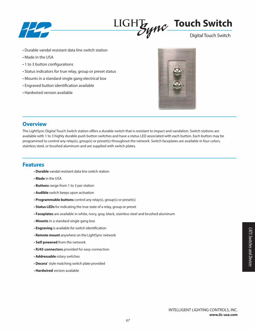
Overview The LightSync Digital Touch Switch station offers a durable switch that is resistant to impact and vandalism. Switch stations areavailable with 1 to 3 highly durable push button switches and have a status LED associated with each button. Each button may beprogrammed to control any relay(s), group(s) or preset(s) throughout the network. Switch faceplates are available in four colors,stainless steel, or brushed aluminum and are supplied with switch plates.
• Durable vandal resistant data line switch station
• Made in the USA
• 1 to 3 button configurations
• Status indicators for true relay, group or preset status
• Mounts in a standard single gang electrical box
• Engraved button identification available
• Hardwired version available
• Durable vandal resistant data line switch station
• Made in the USA
• Buttons range from 1 to 3 per station
• Audible switch beeps upon activation
• Programmable buttons control any relay(s), group(s) or preset(s)
• Status LEDs for indicating the true state of a relay, group or preset
• Faceplates are available in white, ivory, gray, black, stainless steel and brushed aluminum
• Mounts in a standard single gang box
• Engraving is available for switch identification
• Remote mount anywhere on the LightSync network
• Self powered from the network
• RJ45 connectors provided for easy connection
• Addressable rotary switches
• Decora® style matching switch plate provided
• Hardwired version available
Features
InTELLIGEnT LIGHTInG COnTROLS, InC.www.ilc-usa.com
Digital Touch Switch
Touch Switch
67
CAT5 Switches and Devices
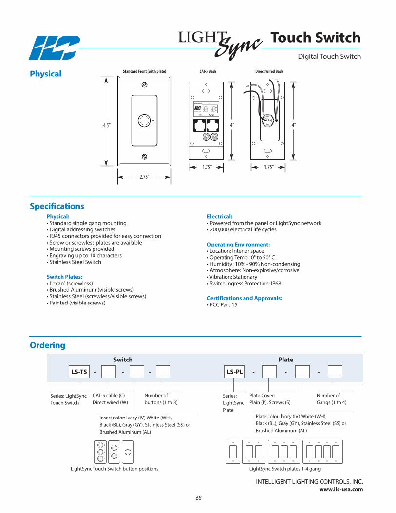
Physical:• Standard single gang mounting• Digital addressing switches• RJ45 connectors provided for easy connection• Screw or screwless plates are available• Mounting screws provided• Engraving up to 10 characters • Stainless Steel Switch
Switch Plates:• Lexan® (screwless) • Brushed Aluminum (visible screws) • Stainless Steel (screwless/visible screws)• Painted (visible screws)
Electrical:• Powered from the panel or LightSync network• 200,000 electrical life cycles
Operating Environment:• Location: Interior space• Operating Temp.: 0° to 50° C • Humidity: 10% - 90% non-condensing • Atmosphere: non-explosive/corrosive • Vibration: Stationary• Switch Ingress Protection: IP68
Certifications and Approvals:• FCC Part 15
Physical
Specifications
Ordering
Insert color: Ivory (IV) White (WH), Black (BL), Gray (Gy), Stainless Steel (SS) orBrushed Aluminum (AL)
Plate color: Ivory (IV) White (WH), Black (BL), Gray (Gy), Stainless Steel (SS) orBrushed Aluminum (AL)
Series: LightSyncTouch Switch
LS-TS - - - - - -
Switch
CAT-5 cable (C)Direct wired (W)
number of buttons (1 to 3)
Series:LightSyncPlate
LS-PL
Plate
Plate Cover: Plain (P), Screws (S)
number of Gangs (1 to 4)
Digital Touch Switch
Touch Switch
800-922-8004
IN
ADDRESS
OUT
Standard Front (with plate) CAT-5 Back Direct Wired Back
1.75”1.75”
4”4”
2.75”
4.5”
InTELLIGEnT LIGHTInG COnTROLS, InC.www.ilc-usa.com
LightSync Switch plates 1-4 gangLightSync Touch Switch button positions
68
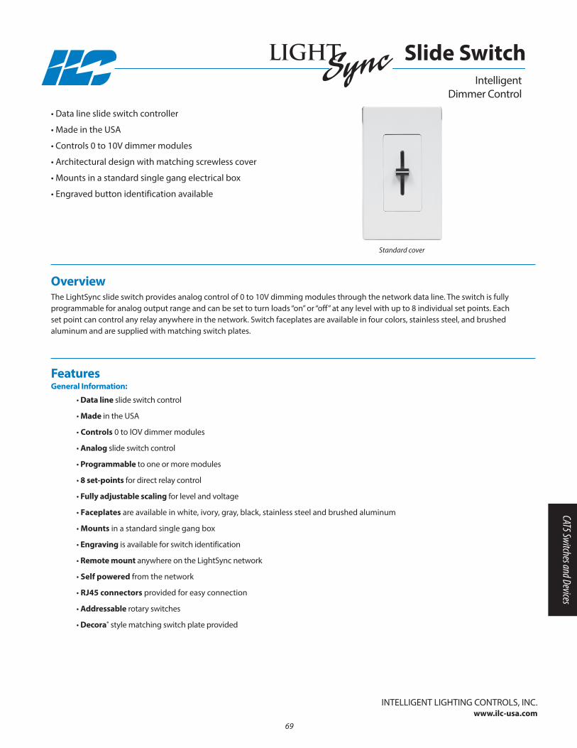
Overview The LightSync slide switch provides analog control of 0 to 10V dimming modules through the network data line. The switch is fullyprogrammable for analog output range and can be set to turn loads “on” or “off” at any level with up to 8 individual set points. Eachset point can control any relay anywhere in the network. Switch faceplates are available in four colors, stainless steel, and brushedaluminum and are supplied with matching switch plates.
• Data line slide switch controller
• Made in the USA
• Controls 0 to 10V dimmer modules
• Architectural design with matching screwless cover
• Mounts in a standard single gang electrical box
• Engraved button identification available
• Data line slide switch control
• Made in the USA
• Controls 0 to lOV dimmer modules
• Analog slide switch control
• Programmable to one or more modules
• 8 set-points for direct relay control
• Fully adjustable scaling for level and voltage
• Faceplates are available in white, ivory, gray, black, stainless steel and brushed aluminum
• Mounts in a standard single gang box
• Engraving is available for switch identification
• Remote mount anywhere on the LightSync network
• Self powered from the network
• RJ45 connectors provided for easy connection
• Addressable rotary switches
• Decora® style matching switch plate provided
Features General Information:
InTELLIGEnT LIGHTInG COnTROLS, InC.www.ilc-usa.com
Intelligent Dimmer Control
Slide Switch
Standard cover
69
CAT5 Switches and Devices
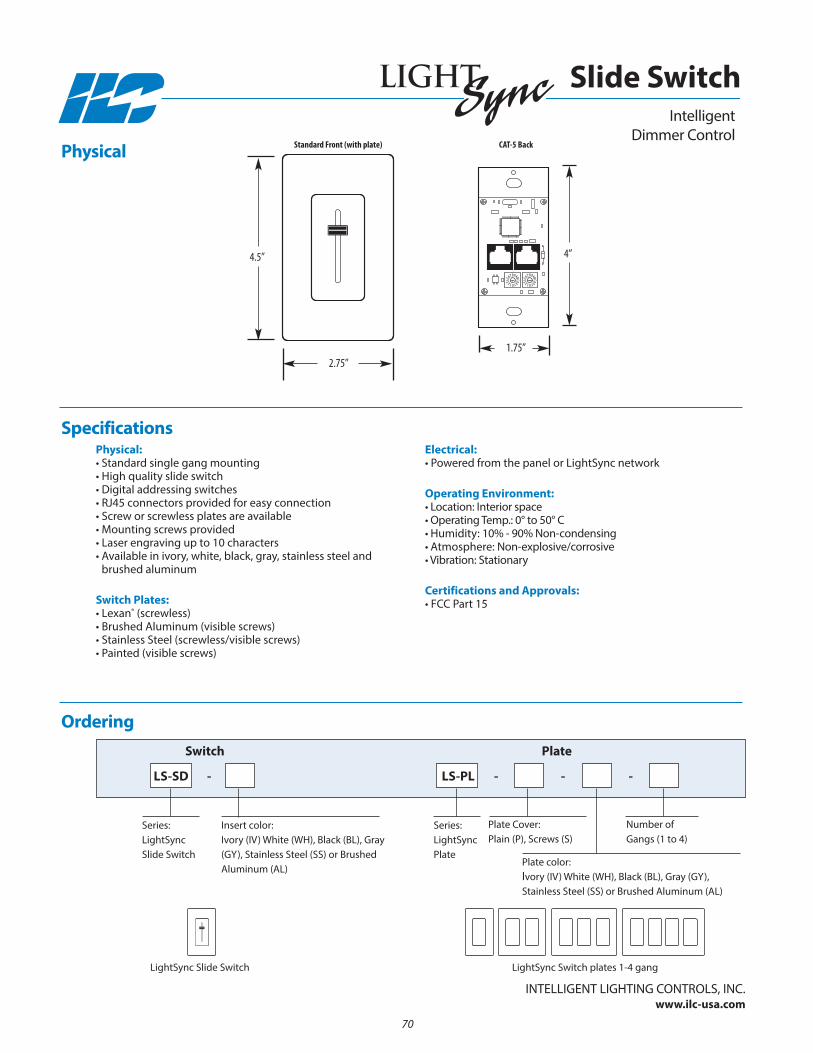
Physical:• Standard single gang mounting• High quality slide switch• Digital addressing switches• RJ45 connectors provided for easy connection• Screw or screwless plates are available• Mounting screws provided• Laser engraving up to 10 characters • Available in ivory, white, black, gray, stainless steel and
brushed aluminum
Switch Plates:• Lexan® (screwless) • Brushed Aluminum (visible screws) • Stainless Steel (screwless/visible screws)• Painted (visible screws)
Electrical:• Powered from the panel or LightSync network
Operating Environment:• Location: Interior space• Operating Temp.: 0° to 50° C • Humidity: 10% - 90% non-condensing • Atmosphere: non-explosive/corrosive • Vibration: Stationary
Certifications and Approvals:• FCC Part 15
Physical
Specifications
Ordering
Insert color: Ivory (IV) White (WH), Black (BL), Gray(Gy), Stainless Steel (SS) or BrushedAluminum (AL)
Plate color: Ivory (IV) White (WH), Black (BL), Gray (Gy), Stainless Steel (SS) or Brushed Aluminum (AL)
Series:LightSyncSlide Switch
LS-SD - - - -
Switch
Series:LightSyncPlate
LS-PL
Plate
Plate Cover: Plain (P), Screws (S)
number of Gangs (1 to 4)
Intelligent Dimmer Control
Slide Switch
InTELLIGEnT LIGHTInG COnTROLS, InC.www.ilc-usa.com
2.75”
4.5”
Standard Front (with plate) CAT-5 Back
1.75”
4”
LightSync Switch plates 1-4 gangLightSync Slide Switch
70
Section 6: LightLEEDer Specialty Add-on Devices
• LightLEEDer DMX 512 Control Modules
• LightLEEDer DMX Driver Modules
• LightSync Motor Control Module
• LightSync Serial Interface Input Control Module• LightSync Conditional Input Module• LightSync Data Line Transient Suppressor
• LightLEEDer Voice Prompted DTMF Telephone
Modules
• LightLEEDer Modem Module• LightSync Device Hub
• LightLEEDer Serial Interface Ethernet Control
Modules
• LightLEEDer Dry Contact Output Board
• LightLEEDer Relay Simulator Register
71
LightLEEDer Specialty Add-on Devices

72
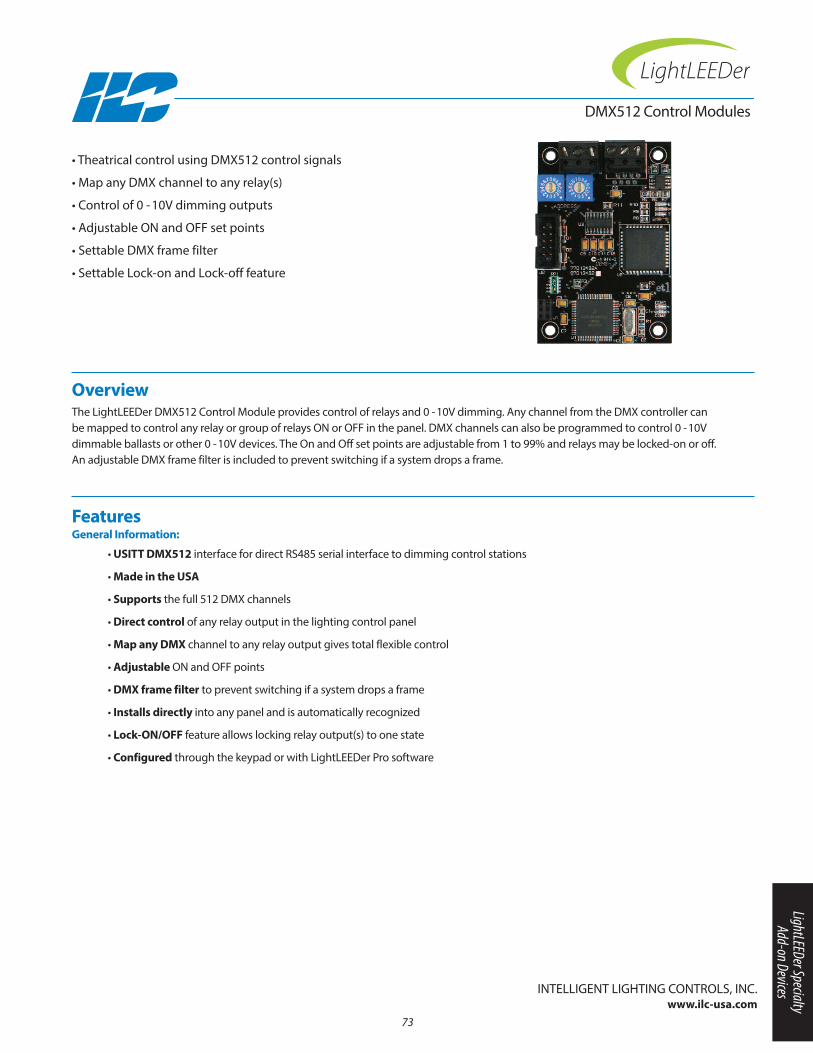
Overview The LightLEEDer DMX512 Control Module provides control of relays and 0 -10V dimming. Any channel from the DMX controller canbe mapped to control any relay or group of relays On or OFF in the panel. DMX channels can also be programmed to control 0 -10Vdimmable ballasts or other 0 -10V devices. The On and Off set points are adjustable from 1 to 99% and relays may be locked-on or off.An adjustable DMX frame filter is included to prevent switching if a system drops a frame.
• Theatrical control using DMX512 control signals
• Map any DMX channel to any relay(s)
• Control of 0 - 10V dimming outputs
• Adjustable On and OFF set points
• Settable DMX frame filter
• Settable Lock-on and Lock-off feature
DMX512 Control Modules
• USITT DMX512 interface for direct RS485 serial interface to dimming control stations
• Made in the USA
• Supports the full 512 DMX channels
• Direct control of any relay output in the lighting control panel
• Map any DMX channel to any relay output gives total flexible control
• Adjustable On and OFF points
• DMX frame filter to prevent switching if a system drops a frame
• Installs directly into any panel and is automatically recognized
• Lock-ON/OFF feature allows locking relay output(s) to one state
• Configured through the keypad or with LightLEEDer Pro software
Features General Information:
InTELLIGEnT LIGHTInG COnTROLS, InC.www.ilc-usa.com
73
LightLEEDer Specialty Add-on Devices
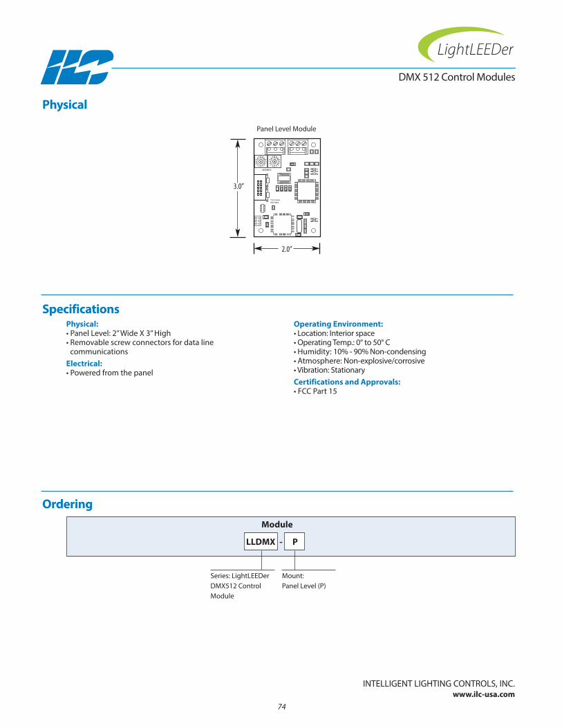
Physical:• Panel Level: 2” Wide X 3” High• Removable screw connectors for data line
communicationsElectrical:• Powered from the panel
Operating Environment:• Location: Interior space• Operating Temp.: 0° to 50° C • Humidity: 10% - 90% non-condensing • Atmosphere: non-explosive/corrosive • Vibration: StationaryCertifications and Approvals:• FCC Part 15
Ordering
DMX 512 Control Modules
Series: LightLEEDer DMX512 Control Module
LLDMX
Module
Mount: Panel Level (P)
Physical
Specifications
InTELLIGEnT LIGHTInG COnTROLS, InC.www.ilc-usa.com
9701349277013492A
ADDRESS
2.0”
3.0”
Panel Level Module
-
74
P

Overview The LightSync DMX Driver Module is designed to drive DMX512 levels from a LightLEEDer lighting controller using RS485 communications. Each LS DMX Driver Module is capable of controlling up to 64 channels per module, per panel in the LightLEEDersystem. Each dimming output channel can be mapped to control from 1 to all of the 512 DMX channels. This module connects to thelocal LightSync port on the LightLEEDer controller and can be mounted in the panel or remotely. The DMX output control channelsare controlled from 0 -100% using the dimming controls in the lighting controller.
• Send DMX512 dimming control signals
• 64 dimming control channels per module
• Map a control channel to any DMX channel
• Control channels controlled by inputs, Presets or other LightLEEDer controls
• Channels are programmable or 1 to 1 control
• Intuitive software provided
• DMX512 output driver
• Supports the full 512 DMX channels
• Direct control of any DMX channel from the lighting control panel
• Map any dimming output channel to any DMX channel
• 64 dimming output channels per panel
• Controlled using LightLEEDer options which include; Timers, Presets, inputs, sliders, and data line devices
• Installs directly into any panel or remotely
• Configured through the keypad or with LightLEEDer Pro software
• DMX mapping can be 1 to 1, or programmable with LightLEEDer DMX Output Map software
Features General Information:
InTELLIGEnT LIGHTInG COnTROLS, InC.www.ilc-usa.com
75
SIICMDMX Driver Module
LightLEEDer Specialty Add-on Devices

Physical:• 3.75" wide X 3.50" high• Screw connector for DMX• USB mini software programming interface• Rotary address and range switches• Configuration dip switches• Status diagnostic LEDs provided• Data line terminator resistor enable jumper• Easy installation into any panelElectrical:• 24VAC @ 150mA
Operating Environment:• Location: Interior space• Operating Temp: 0°-50° C• Humidity: 10%-90% non-condensing• Atmosphere: non-explosive/corrosive• Vibration: StationaryCertifications and Approvals:• UL CUL
Ordering
Series: LightSync DMXDriver Module
LSDMXD
Module
Physical
Specifications
InTELLIGEnT LIGHTInG COnTROLS, InC.www.ilc-usa.com
OUTIN
12VAC
12VAC
CT
77013546 REV A
3.50”
3.75”
DMX Driver Module
76
SIICMDMX Driver Module
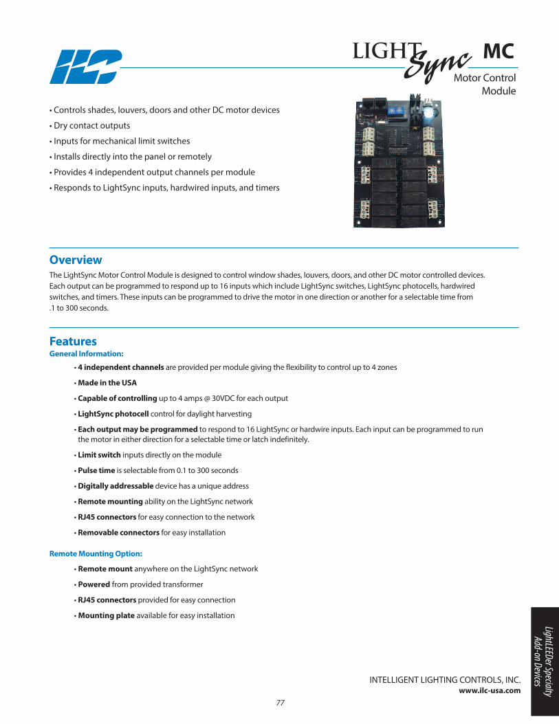
Overview The LightSync Motor Control Module is designed to control window shades, louvers, doors, and other DC motor controlled devices.Each output can be programmed to respond up to 16 inputs which include LightSync switches, LightSync photocells, hardwiredswitches, and timers. These inputs can be programmed to drive the motor in one direction or another for a selectable time from .1 to 300 seconds.
• Controls shades, louvers, doors and other DC motor devices
• Dry contact outputs
• Inputs for mechanical limit switches
• Installs directly into the panel or remotely
• Provides 4 independent output channels per module
• Responds to LightSync inputs, hardwired inputs, and timers
Features General Information:
InTELLIGEnT LIGHTInG COnTROLS, InC.www.ilc-usa.com
• 4 independent channels are provided per module giving the flexibility to control up to 4 zones
• Made in the USA
• Capable of controlling up to 4 amps @ 30VDC for each output
• LightSync photocell control for daylight harvesting
• Each output may be programmed to respond to 16 LightSync or hardwire inputs. Each input can be programmed to runthe motor in either direction for a selectable time or latch indefinitely.
• Limit switch inputs directly on the module
• Pulse time is selectable from 0.1 to 300 seconds
• Digitally addressable device has a unique address
• Remote mounting ability on the LightSync network
• RJ45 connectors for easy connection to the network
• Removable connectors for easy installation
Motor Control Module
MC
• Remote mount anywhere on the LightSync network
• Powered from provided transformer
• RJ45 connectors provided for easy connection
• Mounting plate available for easy installation
Remote Mounting Option:
77
LightLEEDer Specialty Add-on Devices

Physical:• 4.50” Wide X 6.50” High• Removable output connectors• Digital addressing switches• RJ45 connectors for remote mounting optionsElectrical:• Electronics powered from the panel or from
the LightSync network• XFMR: 120, 277 or optional 347 VAC• Motor power from external source• 4 amps @ 30 VDC load capacityConfiguration:• Software programming• Directly through keypad
Operating Environment:• Location: Interior space• Operating Temp.: 0° to 50° C • Humidity: 10% - 90% non-condensing • Atmosphere: non-explosive/corrosive • Vibration: StationaryCertifications and Approvals:• FCC Part 15
Ordering
Series: LightSync Motor Control Module
LSMC
Module
Physical
Specifications
MOTOR 1
MOTOR 2
MOTOR 3
MOTOR 4
MTR1-LS1 LS1BYPASS
LS2BYPASS
LS1BYPASS
IN-1
IN-2
OUT-A
OUT-B
IN-1
IN-2
OUT-A
OUT-B
IN-1
IN-2
OUT-A
OUT-B
IN-1
IN-2
OUT-A
OUT-B
LS2BYPASS
LS1BYPASS
LS2BYPASS
LS1BYPASS
LS2BYPASS
MTR1-LSC
MTR1-LS2
MTR2-LS1
MTR2-LSC
MTR2-LS2
MTR3-LS1
MTR3-LSC
MTR3-LS2
MTR4-LS1
MTR4-LSC
MTR4-LS2
OUTIN
12VAC
12VAC
CT
24VAC CT
4.50”
6.50”
Motor Control Module
MC
InTELLIGEnT LIGHTInG COnTROLS, InC.www.ilc-usa.com
78
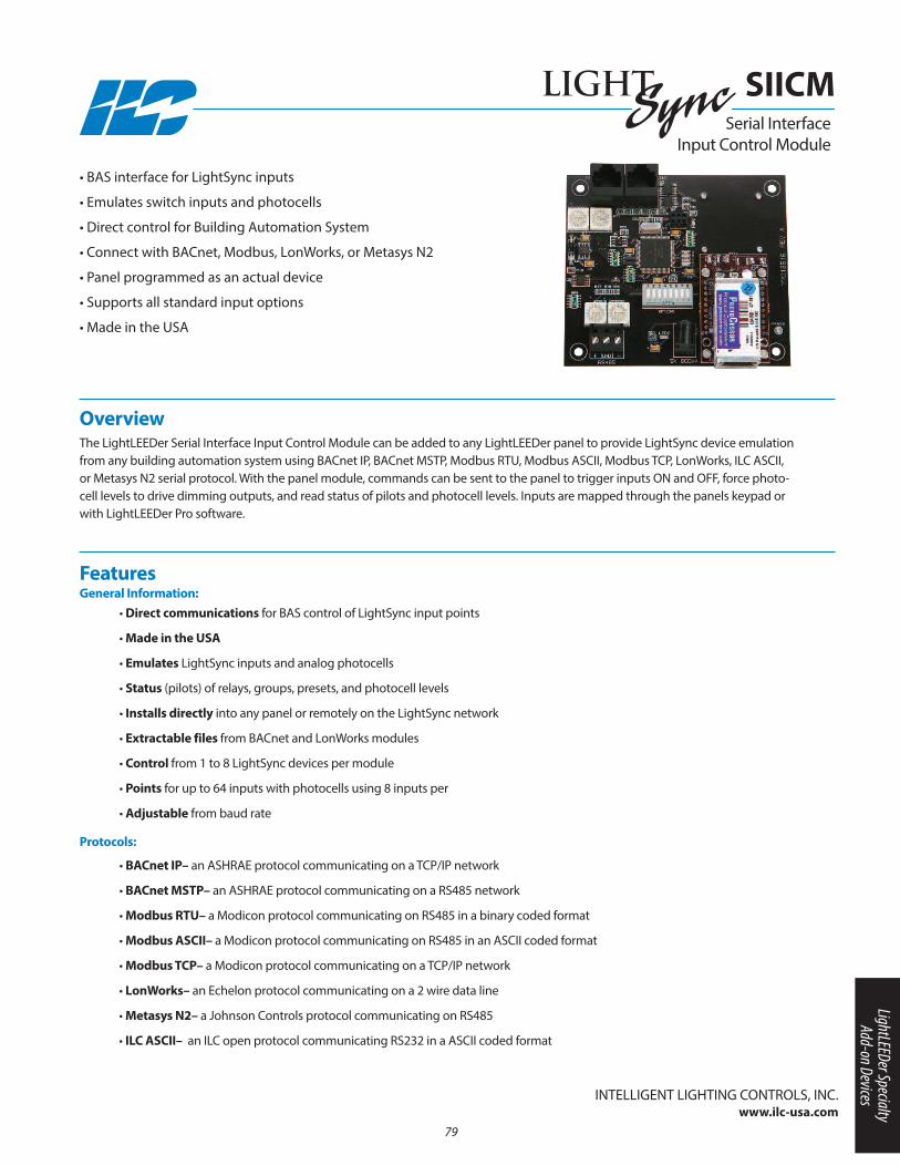
Overview The LightLEEDer Serial Interface Input Control Module can be added to any LightLEEDer panel to provide LightSync device emulationfrom any building automation system using BACnet IP, BACnet MSTP, Modbus RTU, Modbus ASCII, Modbus TCP, LonWorks, ILC ASCII,or Metasys n2 serial protocol. With the panel module, commands can be sent to the panel to trigger inputs On and OFF, force photo-cell levels to drive dimming outputs, and read status of pilots and photocell levels. Inputs are mapped through the panels keypad orwith LightLEEDer Pro software.
• BAS interface for LightSync inputs
• Emulates switch inputs and photocells
• Direct control for Building Automation System
• Connect with BACnet, Modbus, LonWorks, or Metasys n2
• Panel programmed as an actual device
• Supports all standard input options
• Made in the USA
• BACnet IP– an ASHRAE protocol communicating on a TCP/IP network
• BACnet MSTP– an ASHRAE protocol communicating on a RS485 network
• Modbus RTU– a Modicon protocol communicating on RS485 in a binary coded format
• Modbus ASCII– a Modicon protocol communicating on RS485 in an ASCII coded format
• Modbus TCP– a Modicon protocol communicating on a TCP/IP network
• LonWorks– an Echelon protocol communicating on a 2 wire data line
• Metasys N2– a Johnson Controls protocol communicating on RS485
• ILC ASCII– an ILC open protocol communicating RS232 in a ASCII coded format
Features General Information:
InTELLIGEnT LIGHTInG COnTROLS, InC.www.ilc-usa.com
• Direct communications for BAS control of LightSync input points
• Made in the USA
• Emulates LightSync inputs and analog photocells
• Status (pilots) of relays, groups, presets, and photocell levels
• Installs directly into any panel or remotely on the LightSync network
• Extractable files from BACnet and LonWorks modules
• Control from 1 to 8 LightSync devices per module
• Points for up to 64 inputs with photocells using 8 inputs per
• Adjustable from baud rate
Protocols:
79
SIICMSerial Interface
Input Control Module
LightLEEDer Specialty Add-on Devices
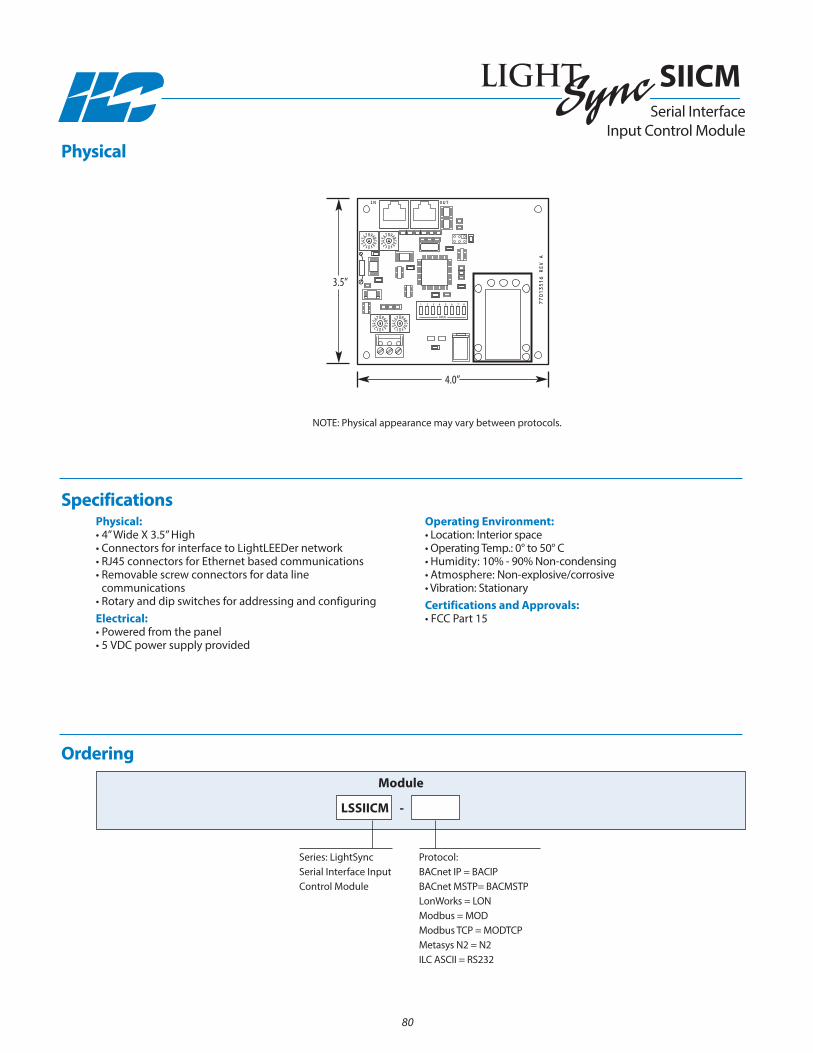
Physical:• 4” Wide X 3.5” High• Connectors for interface to LightLEEDer network• RJ45 connectors for Ethernet based communications• Removable screw connectors for data line
communications• Rotary and dip switches for addressing and configuringElectrical:• Powered from the panel• 5 VDC power supply provided
Operating Environment:• Location: Interior space• Operating Temp.: 0° to 50° C • Humidity: 10% - 90% non-condensing • Atmosphere: non-explosive/corrosive • Vibration: StationaryCertifications and Approvals:• FCC Part 15
Ordering
Series: LightSync Serial Interface InputControl Module
LSSIICM
Module
Protocol: BACnet IP = BACIPBACnet MSTP= BACMSTPLonWorks = LOnModbus = MODModbus TCP = MODTCPMetasys n2 = n2ILC ASCII = RS232
Physical
Specifications
OPEN
1 2 3 4 5 6 7 8
OUTIN
77013516 REV A
3.5”
4.0”
-
nOTE: Physical appearance may vary between protocols.
80
SIICMSerial Interface
Input Control Module

Overview The LightSync Conditional Input Module is designed to accept up to 8 hardwired switch inputs. Each input can be programmed withconditionals related to inputs and pilots in the module. you can setup “AnD”/ “OR” logic schemes for each input that needs to be trueto activate the switch input. This is very useful in certain situations where you want an input active only when certain conditions exist.Any input can be programmed to control any relay(s), group(s), or preset(s) in any or all panels. Each input has an associated pilot sta-tus LED that activates when the input is closed. Inputs have a time-of-day or open/close time of action which could disable the inputor change the relays controlled.
• Provides enhanced conditional hardwired inputs
• Installs directly onto output board or remotely
• 8 inputs per module
• Made in the USA
• Easy non-screw push-to-connect terminals
• Optically isolated inputs protect electronics
• Accepts dry contact closures or optional 12-24VDC signals
• LED pilot input closure status
Features General Information:
• 8 conditional inputs per module
• Conditional input module enhances current LightLEEDer conditionals
• Made in the USA
• Installs directly onto the output board
• Digitally addressable device for a unique address
• Remote mounting option for LightSync network
• RJ45 connectors for remote mounting module
• Connectors are an easy non-screw push-to-connect type
• Optically isolated inputs to protect the electronics
• Accepts dry contact closures or open collector inputs
• Optional module for 12 - 24 VDC signals
• Accepts 2 wire momentary or maintained switch closures
• Switch closure LED status is provided for each input
• Software logic programming
InTELLIGEnT LIGHTInG COnTROLS, InC.www.ilc-usa.com
81
Conditional Input Module
LightLEEDer Specialty Add-on Devices

Remote Mounting Option:• Remote mount anywhere on the local LightSync network• Self powered from the network• RJ45 connectors provided for easy connection• Mounting plate availableSafeguards:• Optically isolated inputs eliminate issues connecting
systems togetherPhysical:• 2.75” Wide 3.50” High• Easy non-screw push-to-connect terminals• Digital addressing switches• Status LED for each input
Electrical:• Powered from the panel or from the LightSync networkOperating Environment:• Location: Interior space• Operating Temperature: 0° to 50° C • Humidity: 10% - 90% non-condensing • Atmosphere: non-explosive/corrosive • Vibration: StationaryCertifications and Approvals:• UL CUL• FCC Part 15
Ordering
Module Option:Panel (P), Remote (R)
Specifications
InTELLIGEnT LIGHTInG COnTROLS, InC.www.ilc-usa.com
Module Type:Dry Contact (O)VOC Input (V)
-
82
Series: LightSyncConditionalInput Module
LSCIM -
W2
W1EXT +V
IN
LSDMSD
77013543A
IN 1
COM
IN 2
COM
COM
COM
COM
COM
IN 5
IN 8
IN 6
IN 3
COM
IN 7
COM
IN 4
EXT COM
-
+
+
-
+
-
OUT
LIGHTSYNCCONDITIONALINPUT MODULE
REFERENCE:
W2
W1EXT +V
IN
LSDMSD
77013543A
IN 1
COM
IN 2
COM
COM
COM
COM
COM
IN 5
IN 8
IN 6
IN 3
COM
IN 7
COM
IN 4
EXT COM
-
+
+
-
+
-
OUT
LIGHTSYNCCONDITIONALINPUT MODULE
REFERENCE:
98 AC
DB
CB
D
9876
45
A
3
7
4
6
53 E
F
0
2 F
0
1E
12
98 AC
DB
CB
D
9876
45
A
3
7
4
6
53 E
F
0
2 F
0
1E
12
3.50” 3.50”
2.75” 2.75”
Remote Mount Panel Mount
Physical
Conditional Input Module

Overview The LightSync Data Line Transient suppressor protects lighting panels and devices from induced spikes and surges on the dataline. Although direct lightning events cannot be completely suppressed, data line surges from magnetic induction or capacitivecoupling can, preventing damage to lighting control equipment. The suppressor features a three stage clamping circuit employ-ing a high capacity gas discharge tube (GOT), 1500W fast clamping transient suppression diodes, and metal oxide varistors (MOV).
• Designed to help protect the LightSync data line from
transient voltage surges and spikes
• Made in the USA
• Protects panels and devices
• Recommended for underground data lines
• Mounting bracket included
• Meets AnSI/IEEE ratings
• Made in the USA
• Data line protection from voltage surges and spikes
• Protects panels and devices
• Suppression for data and power
• Mounts directly in the panel or remotely
• Ideal for underground data cable runs
• Mounting bracket included for easy mounting
• RJ45 connectors provided for easy connection
• Grounding is provided through the mounting bracket
• Power is not required
Features General Information:
InTELLIGEnT LIGHTInG COnTROLS, InC.www.ilc-usa.com
Data LineTransient Suppressor
DTS
83
LightLEEDer Specialty Add-on Devices
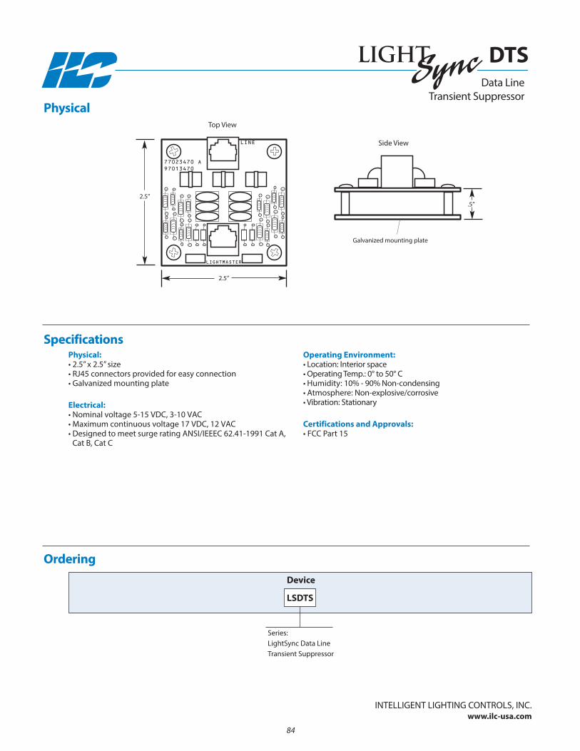
LINE
LIGHTMASTER
77023470 A97013470
Top View
Side View
2.5”.5”
2.5”
Galvanized mounting plate
Physical:• 2.5” x 2.5” size • RJ45 connectors provided for easy connection• Galvanized mounting plate
Electrical:• nominal voltage 5-15 VDC, 3-10 VAC• Maximum continuous voltage 17 VDC, 12 VAC• Designed to meet surge rating AnSI/IEEEC 62.41-1991 Cat A,
Cat B, Cat C
Operating Environment:• Location: Interior space• Operating Temp.: 0° to 50° C • Humidity: 10% - 90% non-condensing • Atmosphere: non-explosive/corrosive • Vibration: Stationary
Certifications and Approvals:• FCC Part 15
Physical
Specifications
Ordering
Series:LightSync Data LineTransient Suppressor
LSDTS
Device
Data LineTransient Suppressor
DTS
InTELLIGEnT LIGHTInG COnTROLS, InC.www.ilc-usa.com
84
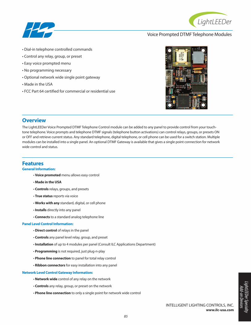
Overview The LightLEEDer Voice Prompted DTMF Telephone Control module can be added to any panel to provide control from your touch-tone telephone. Voice prompts and telephone DTMF signals (telephone button activations) can control relays, groups, or presets Onor OFF and retrieve current status. Any standard telephone, digital telephone, or cell phone can be used for a switch station. Multiplemodules can be installed into a single panel. An optional DTMF Gateway is available that gives a single point connection for networkwide control and status.
• Dial-in telephone controlled commands
• Control any relay, group, or preset
• Easy voice prompted menu
• no programming necessary
• Optional network wide single point gateway
• Made in the USA
• FCC Part 64 certified for commercial or residential use
Voice Prompted DTMF Telephone Modules
• Voice promoted menu allows easy control
• Made in the USA
• Controls relays, groups, and presets
• True status reports via voice
• Works with any standard, digital, or cell phone
• Installs directly into any panel
• Connects to a standard analog telephone line
Features General Information:
• Direct control of relays in the panel
• Controls any panel level relay, group, and preset
• Installation of up to 4 modules per panel (Consult ILC Applications Department)
• Programming is not required, just plug-n-play
• Phone line connection to panel for total relay control
• Ribbon connectors for easy installation into any panel
Panel Level Control Information:
• Network wide control of any relay on the network
• Controls any relay, group, or preset on the network
• Phone line connection to only a single point for network wide control
Network Level Control Gateway Information:
85
InTELLIGEnT LIGHTInG COnTROLS, InC.www.ilc-usa.com
LightLEEDer Specialty Add-on Devices

Physical:• Panel Level: 2” Wide X 3” High• Gateway Level: 6” Wide X 4” High
2” Wide X 3” High• RJll telephone connectorElectrical:• Powered from the panel
Operating Environment:• Location: Interior space• Operating Temp.: 0° to 50° C • Humidity: 10% - 90% non-condensing • Atmosphere: non-explosive/corrosive • Vibration: StationaryCertifications and Approvals:• FCC Part 15• FCC Part 68
Ordering
Voice Prompted DTMF Telephone Modules
Series: LightLEEDer Telephone Interface Module
LLTI
Module
Mount: Panel Level (P)Gateway (G)
Physical
Specifications
InTELLIGEnT LIGHTInG COnTROLS, InC.www.ilc-usa.com
OUTIN
OFF ON
12VAC
12VAC
CT
POWER
24VAC CT
77013491A
2.0”
3.0”4.0”
2.0”
3.0”
6.0”
Panel Level Module
Gateway Level Modules
86
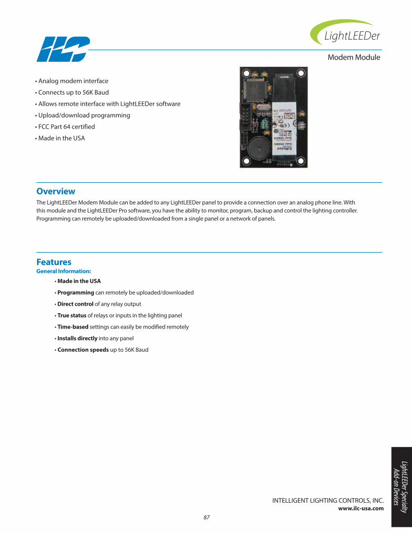
Overview The LightLEEDer Modem Module can be added to any LightLEEDer panel to provide a connection over an analog phone line. Withthis module and the LightLEEDer Pro software, you have the ability to monitor, program, backup and control the lighting controller.Programming can remotely be uploaded/downloaded from a single panel or a network of panels.
• Analog modem interface
• Connects up to 56K Baud
• Allows remote interface with LightLEEDer software
• Upload/download programming
• FCC Part 64 certified
• Made in the USA
Modem Module
• Made in the USA
• Programming can remotely be uploaded/downloaded
• Direct control of any relay output
• True status of relays or inputs in the lighting panel
• Time-based settings can easily be modified remotely
• Installs directly into any panel
• Connection speeds up to 56K Baud
Features General Information:
InTELLIGEnT LIGHTInG COnTROLS, InC.www.ilc-usa.com
87
LightLEEDer Specialty Add-on Devices
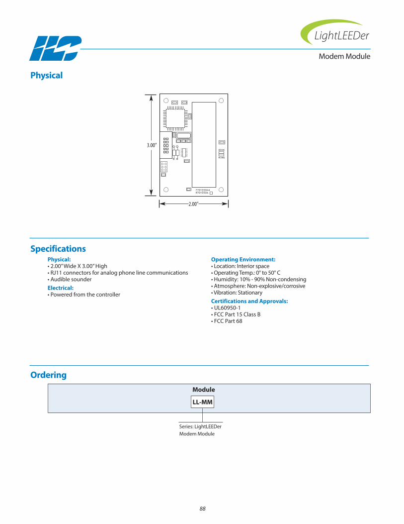
Physical:• 2.00” Wide X 3.00” High• RJ11 connectors for analog phone line communications• Audible sounderElectrical:• Powered from the controller
Operating Environment:• Location: Interior space• Operating Temp.: 0° to 50° C • Humidity: 10% - 90% non-condensing • Atmosphere: non-explosive/corrosive • Vibration: StationaryCertifications and Approvals:• UL60950-1• FCC Part 15 Class B• FCC Part 68
Ordering
Modem Module
Series: LightLEEDer Modem Module
LL-MM
Module
Physical
Specifications
77013504A
HOOK
RING
97013504
3.00”
2.00”
88
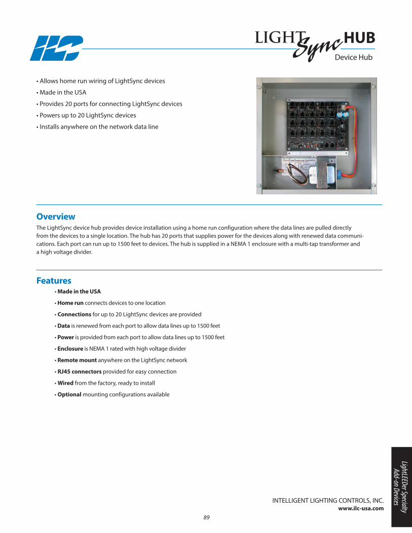
Overview The LightSync device hub provides device installation using a home run configuration where the data lines are pulled directlyfrom the devices to a single location. The hub has 20 ports that supplies power for the devices along with renewed data communi-cations. Each port can run up to 1500 feet to devices. The hub is supplied in a nEMA 1 enclosure with a multi-tap transformer anda high voltage divider.
• Allows home run wiring of LightSync devices
• Made in the USA
• Provides 20 ports for connecting LightSync devices
• Powers up to 20 LightSync devices
• Installs anywhere on the network data line
• Made in the USA
• Home run connects devices to one location
• Connections for up to 20 LightSync devices are provided
• Data is renewed from each port to allow data lines up to 1500 feet
• Power is provided from each port to allow data lines up to 1500 feet
• Enclosure is nEMA 1 rated with high voltage divider
• Remote mount anywhere on the LightSync network
• RJ45 connectors provided for easy connection
• Wired from the factory, ready to install
• Optional mounting configurations available
Features
InTELLIGEnT LIGHTInG COnTROLS, InC.www.ilc-usa.com
Device Hub
HUB
89
LightLEEDer Specialty Add-on Devices
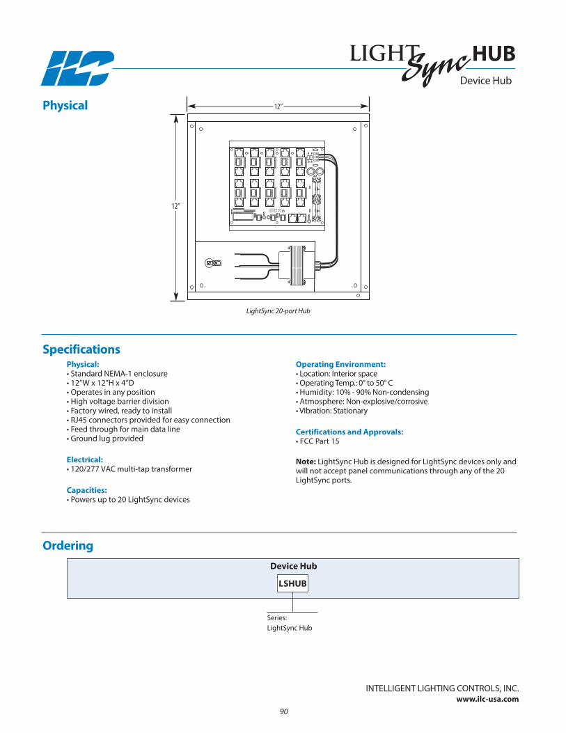
Physical:• Standard nEMA-1 enclosure• 12”W x 12”H x 4”D • Operates in any position• High voltage barrier division• Factory wired, ready to install• RJ45 connectors provided for easy connection• Feed through for main data line• Ground lug provided
Electrical:• 120/277 VAC multi-tap transformer
Capacities:• Powers up to 20 LightSync devices
Operating Environment:• Location: Interior space• Operating Temp.: 0° to 50° C • Humidity: 10% - 90% non-condensing • Atmosphere: non-explosive/corrosive • Vibration: Stationary
Certifications and Approvals:• FCC Part 15
Note: LightSync Hub is designed for LightSync devices only andwill not accept panel communications through any of the 20LightSync ports.
Physical
Specifications
Ordering
Series:LightSync Hub
LSHUB
Device Hub
Device Hub
HUB
12VAC
12VAC
CT
77013442 REV A 97013442 REV
12”
12”
LightSync 20-port Hub
InTELLIGEnT LIGHTInG COnTROLS, InC.www.ilc-usa.com
90
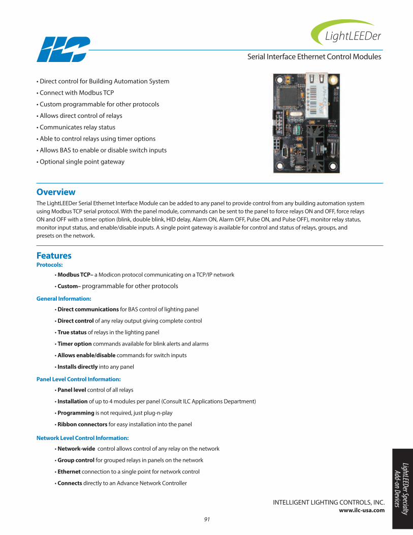
Overview The LightLEEDer Serial Ethernet Interface Module can be added to any panel to provide control from any building automation systemusing Modbus TCP serial protocol. With the panel module, commands can be sent to the panel to force relays On and OFF, force relaysOn and OFF with a timer option (blink, double blink, HID delay, Alarm On, Alarm OFF, Pulse On, and Pulse OFF), monitor relay status,monitor input status, and enable/disable inputs. A single point gateway is available for control and status of relays, groups, and presets on the network.
• Direct control for Building Automation System
• Connect with Modbus TCP
• Custom programmable for other protocols
• Allows direct control of relays
• Communicates relay status
• Able to control relays using timer options
• Allows BAS to enable or disable switch inputs
• Optional single point gateway
Serial Interface Ethernet Control Modules
• Modbus TCP– a Modicon protocol communicating on a TCP/IP network
• Custom– programmable for other protocols
Features Protocols:
InTELLIGEnT LIGHTInG COnTROLS, InC.www.ilc-usa.com
• Direct communications for BAS control of lighting panel
• Direct control of any relay output giving complete control
• True status of relays in the lighting panel
• Timer option commands available for blink alerts and alarms
• Allows enable/disable commands for switch inputs
• Installs directly into any panel
General Information:
• Panel level control of all relays
• Installation of up to 4 modules per panel (Consult ILC Applications Department)
• Programming is not required, just plug-n-play
• Ribbon connectors for easy installation into the panel
Panel Level Control Information:
• Network-wide control allows control of any relay on the network
• Group control for grouped relays in panels on the network
• Ethernet connection to a single point for network control
• Connects directly to an Advance network Controller
Network Level Control Information:
91
LightLEEDer Specialty Add-on Devices
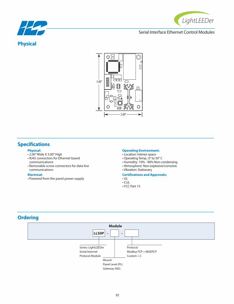
Physical:• 2.00” Wide X 3.00” High• RJ45 connectors for Ethernet based
communications• Removable screw connectors for data line
communicationsElectrical:• Powered from the panel power supply
Operating Environment:• Location: Interior space• Operating Temp.: 0° to 50° C • Humidity: 10% - 90% non-condensing • Atmosphere: non-explosive/corrosive • Vibration: StationaryCertifications and Approvals:• UL• CUL• FCC Part 15
Ordering
Serial Interface Ethernet Control Modules
Series: LightLEEDer Serial InternetProtocol Module
LLSIIP
Module
Protocol: Modbus TCP = MODTCPCustom = C
Mount: Panel Level (PL)Gateway (nG)
Physical
Specifications
+
+
+
-+
-
-
-
-+
+
+
+
--
-
1
9701
3503
7701
3503
A
RX
TX
5VDC800MA
--
+2313
19 21
12
3
18
28
17
11
6 12
22
15
7
8
9
16
10
14
27
20
4
24
25
5
26
2.00”
3.00”
- -
92
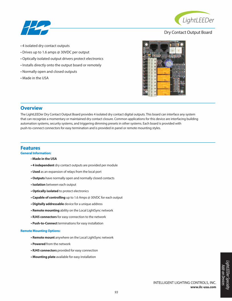
• Made in the USA
• 4 independent dry contact outputs are provided per module
• Used as an expansion of relays from the local port
• Outputs have normally open and normally closed contacts
• Isolation between each output
• Optically isolated to protect electronics
• Capable of controlling up to 1.6 Amps @ 30VDC for each output
• Digitally addressable device for a unique address
• Remote mounting ability on the Local LightSync network
• RJ45 connectors for easy connection to the network
• Push-to-Connect terminations for easy installation
• Remote mount anywhere on the Local LightSync network
• Powered from the network
• RJ45 connectors provided for easy connection
• Mounting plate available for easy installation
Overview The LightLEEDer Dry Contact Output Board provides 4 isolated dry contact digital outputs. This board can interface any system that can recognize a momentary or maintained dry contact closure. Common applications for this device are interfacing building automation systems, security systems, and triggering dimming presets in other systems. Each board is provided with push-to-connect connectors for easy termination and is provided in panel or remote mounting styles.
• 4 isolated dry contact outputs
• Drives up to 1.6 amps @ 30VDC per output
• Optically isolated output drivers protect electronics
• Installs directly onto the output board or remotely
• normally open and closed outputs
• Made in the USA
Features General Information:
Remote Mounting Options:
InTELLIGEnT LIGHTInG COnTROLS, InC.www.ilc-usa.com
Dry Contact Output Board
93
LightLEEDer Specialty Add-on Devices
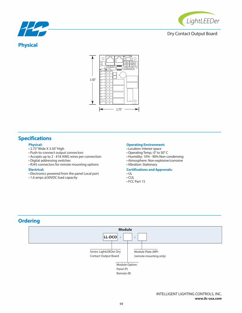
Physical:• 2.75” Wide X 3.50” High• Push-to-connect output connectors• Accepts up to 2 - #18 AWG wires per connection• Digital addressing switches• RJ45 connectors for remote mounting optionsElectrical:• Electronics powered from the panel Local port• 1.6 amps @30VDC load capacity
Operating Environment:• Location: Interior space• Operating Temp.: 0° to 50° C • Humidity: 10% - 90% non-condensing • Atmosphere: non-explosive/corrosive • Vibration: StationaryCertifications and Approvals:• UL• CUL• FCC Part 15
Ordering
Series: LightLEEDer DryContact Output Board
LL-DCO
Module
Module Option: Panel (P)Remote (R)
Module Plate (MP) (remote mounting only)
Physical
Specifications
-
4
LSDMSD
+
-
NC
3
COM
+
NO
COM
NO
1
NC
+
77013525A
COM
2
4
NO
3
NC
4
3
2
COM
2
NO
NC
1
1
+ -
-
2.75”
3.50”
- -
InTELLIGEnT LIGHTInG COnTROLS, InC.www.ilc-usa.com
94
Dry Contact Output Board

• Made in the USA
• Simulated relay output register
• Logic capabilities increased
• Holds relay On and OFF values
• Programs and looks just like a normal relay from the system
• Programming logic used in Input and Output conditionals
• Occupies unused relay points in a panel
• Mounts directly in the panel
• Powered directly from the data line
Overview The LightLEEDer Relay Simulator Register is a device designed to provide an internal register that can be controlled like a relay in the panel. By adding this to the panel, simulated relays can be turned On or OFF and be used in conjunction with Input or Relay conditionals to obtain complicated logic programming. This device is connected to the panels Local data port and can be configuredas simulated relays beyond the physical relays in the panel.
• Made in the USA
• Relay simulator register
• Adds logic control to system
• Holds On or OFF relay logic
• Can be used with relay or input conditionals
• Uses unused relay points in a panel
Features General Information:
InTELLIGEnT LIGHTInG COnTROLS, InC.www.ilc-usa.com
Relay Simulator Register
95
LightLEEDer Specialty Add-on Devices

Physical:• 2.0" wide X 3.00" high• Data In and Data OUT RJ45 connectors• Address switch• Relay count switchElectrical:• Powered directly from the data line
Operating Environment:• Location: Interior space• Operating Temp.: 0° to 50° C • Humidity: 10% - 90% non-condensing • Atmosphere: non-explosive/corrosive • Vibration: StationaryCertifications and Approvals:• UL• CUL• FCC Part 15
Ordering
Series: LightLEEDerRelay Simulator Register
LL-RSR
Module
Physical
Specifications
IN OUT
77013526A
2.00”
3.00”
InTELLIGEnT LIGHTInG COnTROLS, InC.www.ilc-usa.com
96
Relay Simulator Register
Section 7: ILC LightLEEDer Retrofit Lighting Control Panels
• LightLEEDer Retrofit Package
• LightLEEDer-24/40/48Microlite® Retrofit Insert
• LightLEEDer-8X Retrofit Insert
97
ILC LightLEEDer Retrofit Lighting Control Panels

98
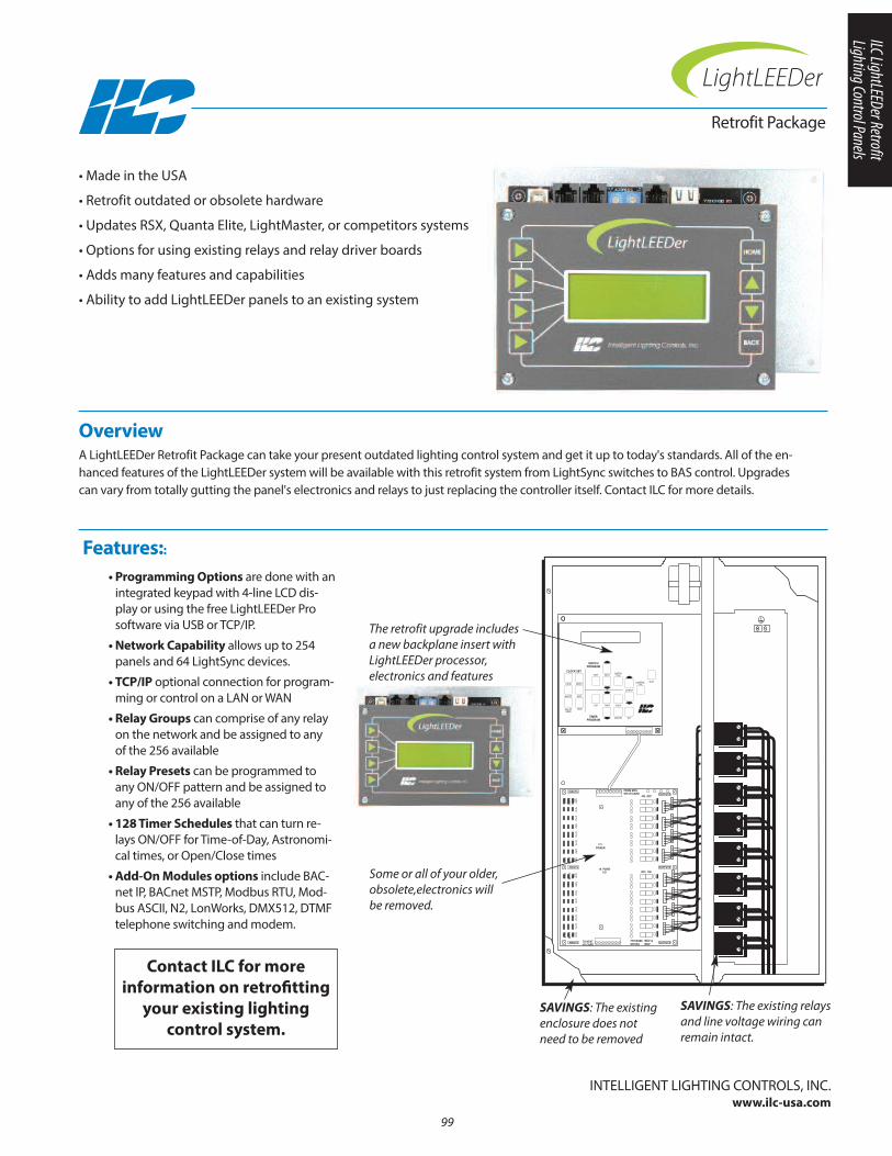
Retrofit Package
Overview A LightLEEDer Retrofit Package can take your present outdated lighting control system and get it up to today's standards. All of the en-hanced features of the LightLEEDer system will be available with this retrofit system from LightSync switches to BAS control. Upgradescan vary from totally gutting the panel's electronics and relays to just replacing the controller itself. Contact ILC for more details.
• Made in the USA
• Retrofit outdated or obsolete hardware
• Updates RSX, Quanta Elite, LightMaster, or competitors systems
• Options for using existing relays and relay driver boards
• Adds many features and capabilities
• Ability to add LightLEEDer panels to an existing system
Features::
99
INPUTS
OFF
COM
ON
OUTPUTSFROM MCUOR I/O CARD
TO NEXTI/O CARD
77013300 REV A970133 REV
ON OFF
POWER
16 POINTI/O
INPUTS OUTPUTS
INPUTS OUTPUTS
OFF
COM
ON
OFF
COM
ON
OFF ON
OFF
COM
ON
CLOCK SET
TIMERPROGRAM
HOUR MONTH
MINUTE DATE
DAY OFWEEK
YEAR
EDIT
EDIT
SWITCHTYPE
CONTROLTYPE
INPUT
TIMER HOUR
MINUTE DAY
OUTPUT
SWITCHPROGRAM
QUIT
• Programming Options are done with anintegrated keypad with 4-line LCD dis-play or using the free LightLEEDer Prosoftware via USB or TCP/IP.
• Network Capability allows up to 254panels and 64 LightSync devices.
• TCP/IP optional connection for program-ming or control on a LAn or WAn
• Relay Groups can comprise of any relayon the network and be assigned to anyof the 256 available
• Relay Presets can be programmed toany On/OFF pattern and be assigned toany of the 256 available
• 128 Timer Schedules that can turn re-lays On/OFF for Time-of-Day, Astronomi-cal times, or Open/Close times
• Add-On Modules options include BAC-net lP, BACnet MSTP, Modbus RTU, Mod-bus ASCII, n2, LonWorks, DMX512, DTMFtelephone switching and modem.
The retrofit upgrade includes a new backplane insert withLightLEEDer processor, electronics and features
Some or all of your older, obsolete,electronics will be removed.
SAVINGS: The existingenclosure does notneed to be removed
SAVINGS: The existing relaysand line voltage wiring can remain intact.
InTELLIGEnT LIGHTInG COnTROLS, InC.www.ilc-usa.com
Contact ILC for more information on retrofitting
your existing lighting control system.
ILC LightLEEDer Retrofit Lighting Control Panels

100
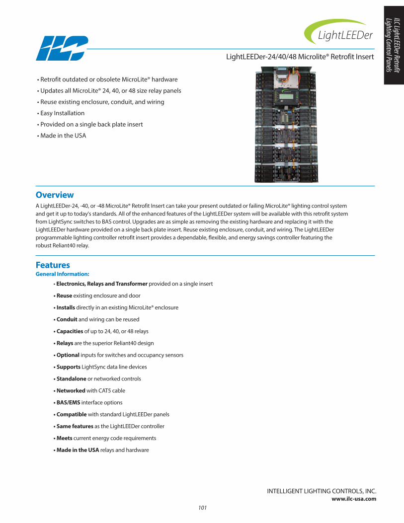
LightLEEDer-24/40/48 Microlite® Retrofit Insert
Overview A LightLEEDer-24, -40, or -48 MicroLite® Retrofit Insert can take your present outdated or failing MicroLite® lighting control systemand get it up to today's standards. All of the enhanced features of the LightLEEDer system will be available with this retrofit systemfrom LightSync switches to BAS control. Upgrades are as simple as removing the existing hardware and replacing it with theLightLEEDer hardware provided on a single back plate insert. Reuse existing enclosure, conduit, and wiring. The LightLEEDer programmable lighting controller retrofit insert provides a dependable, flexible, and energy savings controller featuring the robust Reliant40 relay.
• Retrofit outdated or obsolete MicroLite® hardware
• Updates all MicroLite® 24, 40, or 48 size relay panels
• Reuse existing enclosure, conduit, and wiring
• Easy Installation
• Provided on a single back plate insert
• Made in the USA
Features General Information:
• Electronics, Relays and Transformer provided on a single insert
• Reuse existing enclosure and door
• Installs directly in an existing MicroLite® enclosure
• Conduit and wiring can be reused
• Capacities of up to 24, 40, or 48 relays
• Relays are the superior Reliant40 design
• Optional inputs for switches and occupancy sensors
• Supports LightSync data line devices
• Standalone or networked controls
• Networked with CAT5 cable
• BAS/EMS interface options
• Compatible with standard LightLEEDer panels
• Same features as the LightLEEDer controller
• Meets current energy code requirements
• Made in the USA relays and hardware
101
InTELLIGEnT LIGHTInG COnTROLS, InC.www.ilc-usa.com
ILC LightLEEDer Retrofit Lighting Control Panels
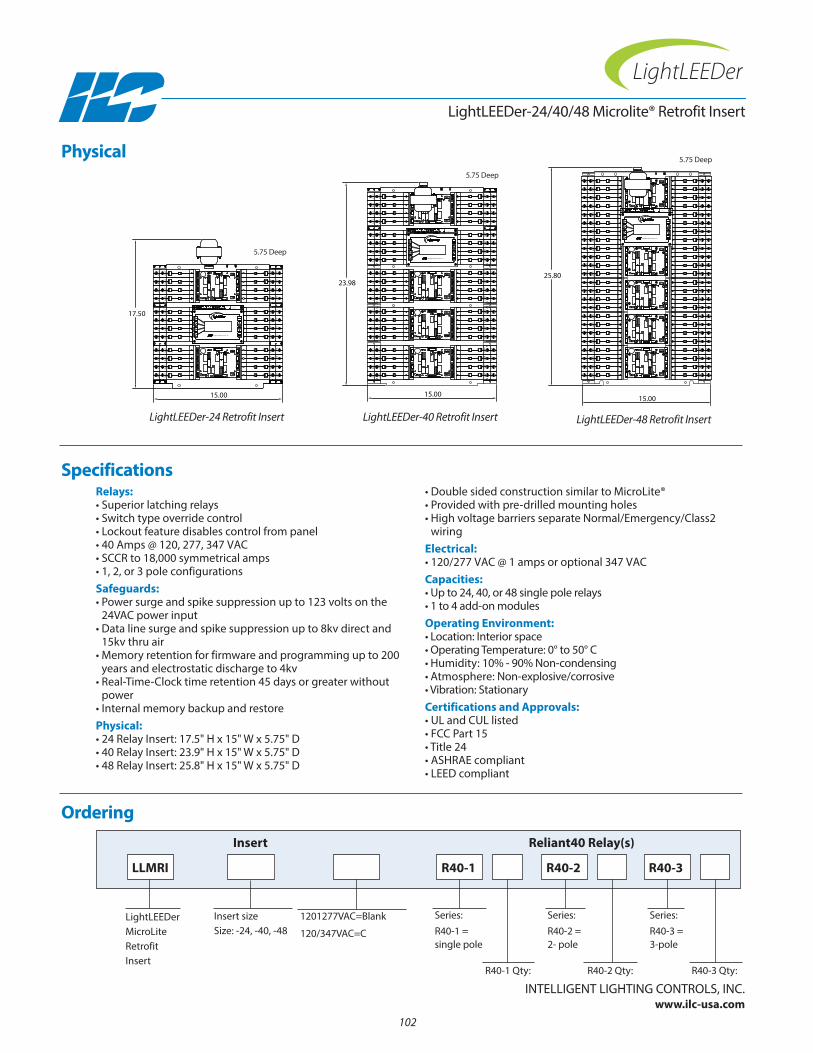
CK MA
L
N NE
AD
FFOLO O
NO
R
LILO
CK MA
L
N NE
AD
FFOLO O
NO
R
LILO
CK MA
L
N NE
AD
FFOLO O
NO
R
LILO
CK MA
L
N NE
AD
FFOLO O
NO
R
LILO
CKMA
L
NNE
AD
FFO LOO NO
R
LI
LO
CKMA
L
NNE
AD
FFO LOO NO
R
LI
LO
CKMA
L
NNE
AD
FFO LOO NO
R
LI
LO
CKMA
L
NNE
AD
FFO LOO NO
R
LI
LO
CK MA
L
N NE
AD
FFOLO O
NO
R
LILO
CKMA
L
NNE
AD
FFO LOO NO
R
LI
LO
CK MA
L
N NE
AD
FFOLO O
NO
R
LILO
CK MA
L
N NE
AD
FFOLO O
NO
R
LILO
CK MA
L
N NE
AD
FFOLO O
NO
R
LILO
CKMA
L
NNE
AD
FFO LOO NO
R
LI
LO
CKMA
L
NNE
AD
FFO LOO NO
R
LI
LO
CKMA
L
NNE
AD
FFO LOO NO
R
LI
LO
CK MA
L
N NE
AD
FFOLO O
NO
R
LILO
CK MA
L
N NE
AD
FFOLO O
NO
R
LILO
CK MA
L
N NE
AD
FFOLO O
NO
R
LILO
CK MA
L
N NE
AD
FFOLO O
NO
R
LILO
CKMA
L
NNE
AD
FFO LOO NO
R
LI
LO
CKMA
L
NNE
AD
FFO LOO NO
R
LI
LO
CKMA
L
NNE
AD
FFO LOO NO
R
LI
LO
CKMA
L
NNE
AD
FFO LOO NO
R
LI
LO
CK MA
L
N NE
AD
FFOLO O
NO
R
LILO
CKMA
L
NNE
AD
FFO LOO NO
R
LI
LO
CK MA
L
N NE
AD
FFOLO O
NO
R
LILO
CK MA
L
N NE
AD
FFOLO O
NO
R
LILO
CK MA
L
N NE
AD
FFOLO O
NO
R
LILO
CKMA
L
NNE
AD
FFO LOO NO
R
LI
LO
CKMA
L
NNE
AD
FFO LOO NO
R
LI
LO
CKMA
L
NNE
AD
FFO LOO NO
R
LI
LO
CK MA
L
N NE
AD
FFOLO O
NO
R
LILO
CKMA
L
NNE
AD
FFO LOO NO
R
LI
LO
CK MA
L
N NE
AD
FFOLO O
NO
R
LILO
CK MA
L
N NE
AD
FFOLO O
NO
R
LILO
CK MA
L
N NE
AD
FFOLO O
NO
R
LILO
CKMA
L
NNE
AD
FFO LOO NO
R
LI
LO
CKMA
L
NNE
AD
FFO LOO NO
R
LI
LO
CKMA
L
NNE
AD
FFO LOO NO
R
LI
LO
CK MA
L
N NE
AD
FFOLO O
NO
R
LILO
CKMA
L
NNE
AD
FFO LOO NO
R
LI
LO
CK MA
L
N NE
AD
FFOLO O
NO
R
LILO
CK MA
L
N NE
AD
FFOLO O
NO
R
LILO
CK MA
L
N NE
AD
FFOLO O
NO
R
LILO
CKMA
L
NNE
AD
FFO LOO NO
R
LI
LO
CKMA
L
NNE
AD
FFO LOO NO
R
LI
LO
CKMA
L
NNE
AD
FFO LOO NO
R
LI
LO
CK MA
L
N NE
AD
FFOLO O
NO
R
LILO
CK MA
L
N NE
AD
FFOLO O
NO
R
LILO
CK MA
L
N NE
AD
FFOLO O
NO
R
LILO
CK MA
L
N NE
AD
FFOLO O
NO
R
LILO
CKMA
L
NNE
AD
FFO LOO NO
R
LI
LO
CKMA
L
NNE
AD
FFO LOO NO
R
LI
LO
CKMA
L
NNE
AD
FFO LOO NO
R
LI
LO
CKMA
L
NNE
AD
FFO LOO NO
R
LI
LO
CK MA
L
N NE
AD
FFOLO O
NO
R
LILO
CK MA
L
N NE
AD
FFOLO O
NO
R
LILO
CK MA
L
N NE
AD
FFOLO O
NO
R
LILO
CK MA
L
N NE
AD
FFOLO O
NO
R
LILO
CKMA
L
NNE
AD
FFO LOO NO
R
LI
LO
CKMA
L
NNE
AD
FFO LOO NO
R
LI
LO
CKMA
L
NNE
AD
FFO LOO NO
R
LI
LO
CKMA
L
NNE
AD
FFO LOO NO
R
LI
LO
CK MA
L
N NE
AD
FFOLO O
NO
R
LILO
CKMA
L
NNE
AD
FFO LOO NO
R
LI
LO
CK MA
L
N NE
AD
FFOLO O
NO
R
LILO
CK MA
L
N NE
AD
FFOLO O
NO
R
LILO
CK MA
L
N NE
AD
FFOLO O
NO
R
LILO
CKMA
L
NNE
AD
FFO LOO NO
R
LI
LO
CKMA
L
NNE
AD
FFO LOO NO
R
LI
LO
CKMA
L
NNE
AD
FFO LOO NO
R
LI
LO
CK MA
L
N NE
AD
FFOLO O
NO
R
LILO
CKMA
L
NNE
AD
FFO LOO NO
R
LI
LO
CK MA
L
N NE
AD
FFOLO O
NO
R
LILO
CK MA
L
N NE
AD
FFOLO O
NO
R
LILO
CK MA
L
N NE
AD
FFOLO O
NO
R
LILO
CKMA
L
NNE
AD
FFO LOO NO
R
LI
LO
CKMA
L
NNE
AD
FFO LOO NO
R
LI
LO
CKMA
L
NNE
AD
FFO LOO NO
R
LI
LO
CK MA
L
N NE
AD
FFOLO O
NO
R
LILO
CKMA
L
NNE
AD
FFO LOO NO
R
LI
LO
CK MA
L
N NE
AD
FFOLO O
NO
R
LILO
CK MA
L
N NE
AD
FFOLO O
NO
R
LILO
CK MA
L
N NE
AD
FFOLO O
NO
R
LILO
CKMA
L
NNE
AD
FFO LOO NO
R
LI
LO
CKMA
L
NNE
AD
FFO LOO NO
R
LI
LO
CKMA
L
NNE
AD
FFO LOO NO
R
LI
LO
CK MA
L
N NE
AD
FFOLO O
NO
R
LILO
CKMA
L
NNE
AD
FFO LOO NO
R
LI
LO
CK MA
L
N NE
AD
FFOLO O
NO
R
LILO
CK MA
L
N NE
AD
FFOLO O
NO
R
LILO
CK MA
L
N NE
AD
FFOLO O
NO
R
LILO
CKMA
L
NNE
AD
FFO LOO NO
R
LI
LO
CKMA
L
NNE
AD
FFO LOO NO
R
LI
LO
CKMA
L
NNE
AD
FFO LOO NO
R
LI
LO
CK MA
L
N NE
AD
FFOLO O
NO
R
LILO
CKMA
L
NNE
AD
FFO LOO NO
R
LI
LO
CK MA
L
N NE
AD
FFOLO O
NO
R
LILO
CK MA
L
N NE
AD
FFOLO O
NO
R
LILO
CK MA
L
N NE
AD
FFOLO O
NO
R
LILO
CKMA
L
NNE
AD
FFO LOO NO
R
LI
LO
CKMA
L
NNE
AD
FFO LOO NO
R
LI
LO
CKMA
L
NNE
AD
FFO LOO NO
R
LI
LO
CK MA
L
N NE
AD
FFOLO O
NO
R
LILO
CKMA
L
NNE
AD
FFO LOO NO
R
LI
LO
CK MA
L
N NE
AD
FFOLO O
NO
R
LILO
CK MA
L
N NE
AD
FFOLO O
NO
R
LILO
CK MA
L
N NE
AD
FFOLO O
NO
R
LILO
CKMA
L
NNE
AD
FFO LOO NO
R
LI
LO
CKMA
L
NNE
AD
FFO LOO NO
R
LI
LO
CKMA
L
NNE
AD
FFO LOO NO
R
LI
LO
POWER
77013488A97013488
RLY 1RLY 3
RLY 5RLY 7
RLY
2RL
Y 4
RLY
6RL
Y 8
+-
+-
-+
24VAC CT
24VAC CT
15.00
POWER
77013488A97013488
RLY 1RLY 3
RLY 5RLY 7
RLY
2RL
Y 4
RLY
6RL
Y 8
+-
+-
-+
24VAC CT
24VAC CT
17.50
POWER
77013488A97013488
RLY 1RLY 3
RLY 5RLY 7
RLY
2RL
Y 4
RLY
6RL
Y 8
+-
+-
-+
24VAC CT
24VAC CT
POWER
77013488A97013488
RLY 1RLY 3
RLY 5RLY 7
RLY
2RL
Y 4
RLY
6RL
Y 8
+-
+-
-+
24VAC CT
24VAC CT
POWER
77013488A97013488
RLY 1RLY 3
RLY 5RLY 7
RLY
2RL
Y 4
RLY
6RL
Y 8
+-
+-
-+
24VAC CT
24VAC CT
POWER
77013488A97013488
RLY 5RLY 7
RLY
2RL
Y 4
RLY
6RL
Y 8
+-
-+
24VAC CT
24VAC CT
15.00
23.98
POWER
77013488A97013488
RLY 1RLY 3
RLY 5RLY 7
RLY
2RL
Y 4
RLY
6RL
Y 8
+-
+-
-+
24VAC CT
24VAC CT
POWER
77013488A97013488
RLY 1RLY 3
RLY 5RLY 7
RLY
2RL
Y 4
RLY
6RL
Y 8
+-
+-
-+
24VAC CT
24VAC CT
POWER
77013488A97013488
RLY 1RLY 3
RLY 5RLY 7
RLY
2RL
Y 4
RLY
6RL
Y 8
+-
+-
-+
24VAC CT
24VAC CT
POWER
77013488A97013488
RLY 1RLY 3
RLY 5RLY 7
RLY
2RL
Y 4
RLY
6RL
Y 8
+-
+-
-+
24VAC CT
24VAC CT
POWER
77013488A97013488
RLY 5RLY 7
RLY
2RL
Y 4
RLY
6RL
Y 8
+-
-+
24VAC CT
24VAC CT
15.00
25.80
77013490 R1
TCP-IP
USB
0 0
F E
BD
CA
2 1E
1 F2
35 6
4
7
3
A
54
6 7 8 9
DBC
8 9
OUT LSIN ADDRESS
OUTIN OUT
77013490 R1
TCP-IP
USB
0 0
F E
BD
CA
2 1E
1 F2
356
4
7
3
A
54
6 7 8 9
DBC
8 9
OUT LSIN ADDRESS
OUTIN OUT
77013490 R10 0
F E
BD
CA
2 1E
1 F2
35 6
4
7
3
A
54
6 7 8 9
DBC
8 9
OUT LSIN ADDRESS
Intelligent Lighting Controls, Inc.
Intelligent Lighting Controls, Inc.
Intelligent Lighting Controls, Inc.
Relays:• Superior latching relays• Switch type override control• Lockout feature disables control from panel• 40 Amps @ 120, 277, 347 VAC• SCCR to 18,000 symmetrical amps• 1, 2, or 3 pole configurationsSafeguards:• Power surge and spike suppression up to 123 volts on the
24VAC power input• Data line surge and spike suppression up to 8kv direct and
15kv thru air• Memory retention for firmware and programming up to 200
years and electrostatic discharge to 4kv• Real-Time-Clock time retention 45 days or greater without
power• Internal memory backup and restorePhysical:• 24 Relay Insert: 17.5" H x 15" W x 5.75" D• 40 Relay Insert: 23.9" H x 15" W x 5.75" D• 48 Relay Insert: 25.8" H x 15" W x 5.75" D
• Double sided construction similar to MicroLite®• Provided with pre-drilled mounting holes• High voltage barriers separate normal/Emergency/Class2
wiringElectrical:• 120/277 VAC @ 1 amps or optional 347 VACCapacities:• Up to 24, 40, or 48 single pole relays• 1 to 4 add-on modules Operating Environment:• Location: Interior space• Operating Temperature: 0° to 50° C • Humidity: 10% - 90% non-condensing • Atmosphere: non-explosive/corrosive • Vibration: StationaryCertifications and Approvals:• UL and CUL listed• FCC Part 15• Title 24• ASHRAE compliant• LEED compliant
Ordering
LightLEEDer-24/40/48 Microlite® Retrofit Insert
Physical
Specifications
InTELLIGEnT LIGHTInG COnTROLS, InC.www.ilc-usa.com
102
Insert size Size: -24, -40, -48
LightLEEDerMicroLiteRetrofitInsert
Series:R40-1 = single pole
R40-1 Qty:
1201277VAC=Blank
120/347VAC=C
LLMRI R40-1 R40-2 R40-3
Insert
Series:R40-2 = 2- pole
R40-2 Qty: R40-3 Qty:
Series:R40-3 = 3-pole
Reliant40 Relay(s)
LightLEEDer-24 Retrofit Insert
5.75 Deep
5.75 Deep
5.75 Deep
LightLEEDer-40 Retrofit Insert LightLEEDer-48 Retrofit Insert
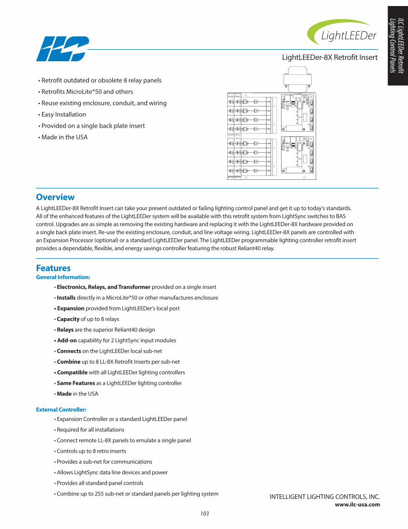
LightLEEDer-8X Retrofit Insert
Overview A LightLEEDer-8X Retrofit Insert can take your present outdated or failing lighting control panel and get it up to today's standards. All of the enhanced features of the LightLEEDer system will be available with this retrofit system from LightSync switches to BAS control. Upgrades are as simple as removing the existing hardware and replacing it with the LightLEEDer-8X hardware provided on a single back plate insert. Re-use the existing enclosure, conduit, and line voltage wiring. LightLEEDer-8X panels are controlled withan Expansion Processor (optional) or a standard LightLEEDer panel. The LightLEEDer programmable lighting controller retrofit insertprovides a dependable, flexible, and energy savings controller featuring the robust Reliant40 relay.
• Retrofit outdated or obsolete 8 relay panels
• Retrofits MicroLite®50 and others
• Reuse existing enclosure, conduit, and wiring
• Easy Installation
• Provided on a single back plate insert
• Made in the USA
Features General Information:
• Electronics, Relays, and Transformer provided on a single insert
• Installs directly in a MicroLite®50 or other manufactures enclosure
• Expansion provided from LightLEEDer's local port
• Capacity of up to 8 relays
• Relays are the superior Reliant40 design
• Add-on capability for 2 LightSync input modules
• Connects on the LightLEEDer local sub-net
• Combine up to 8 LL-8X Retrofit Inserts per sub-net
• Compatible with all LightLEEDer lighting controllers
• Same Features as a LightLEEDer lighting controller
• Made in the USA
103
• Expansion Controller or a standard LightLEEDer panel
• Required for all installations
• Connect remote LL-8X panels to emulate a single panel
• Controls up to 8 retro inserts
• Provides a sub-net for communications
• Allows LightSync data line devices and power
• Provides all standard panel controls
• Combine up to 255 sub-net or standard panels per lighting system
External Controller:
InTELLIGEnT LIGHTInG COnTROLS, InC.www.ilc-usa.com
+ -
+
IN
- +
-
+ -
+
LSDIN
-
MSD
+
-
OUT
CK
MA
L
NNE
AD
FFO LOO NO
R
LI
LO
CK
MA
L
NNE
AD
FFO LOO NO
R
LI
LO
CK
MA
L
NNE
AD
FFO LOO NO
R
LI
LO
CK
MA
L
NNE
AD
FFO LOO NO
R
LI
LO
CK
MA
L
NNE
AD
FFO LOO NO
R
LI
LO
CK
MA
L
NNE
AD
FFO LOO NO
R
LI
LO
CK
MA
L
NNE
AD
FFO LOO NO
R
LI
LO
CK
MA
L
NNE
AD
FFO LOO NO
R
LI
LO
24VAC CT
RLY
1RL
Y 2
RLY
3RL
Y 4
TX
RX
9701350577013505B
24VAC CT
RLY
1RL
Y 2
RLY
3RL
Y 4
TX
RX
9701350577013505B
ILC LightLEEDer Retrofit Lighting Control Panels
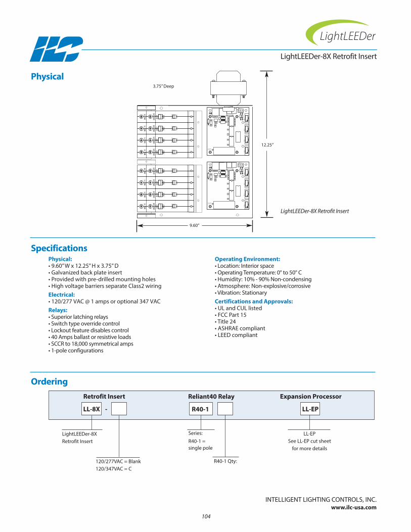
Physical:• 9.60” W x 12.25” H x 3.75” D• Galvanized back plate insert• Provided with pre-drilled mounting holes• High voltage barriers separate Class2 wiringElectrical:• 120/277 VAC @ 1 amps or optional 347 VACRelays:• Superior latching relays• Switch type override control• Lockout feature disables control• 40 Amps ballast or resistive loads• SCCR to 18,000 symmetrical amps• 1-pole configurations
Operating Environment:• Location: Interior space• Operating Temperature: 0° to 50° C • Humidity: 10% - 90% non-condensing • Atmosphere: non-explosive/corrosive • Vibration: StationaryCertifications and Approvals:• UL and CUL listed• FCC Part 15• Title 24• ASHRAE compliant• LEED compliant
Ordering
LightLEEDer-8X Retrofit Insert
LightLEEDer-8XRetrofit Insert
LL-8X
Retrofit Insert Expansion Processor
Physical
Specifications
InTELLIGEnT LIGHTInG COnTROLS, InC.www.ilc-usa.com
LL-EPSee LL-EP cut sheet
for more details
LL-EP
104
Series:R40-1 = single pole
R40-1 Qty:
R40-1
Reliant40 Relay
120/277VAC = Blank120/347VAC = C
-
+ -
+
IN
- +
-
+ -
+
LSDIN
-
MSD
+
-
OUT
CK
MA
L
NNE
AD
FFO LOO NO
R
LI
LO
CK
MA
L
NNE
AD
FFO LOO NO
R
LI
LO
CK
MA
L
NNE
AD
FFO LOO NO
R
LI
LO
CK
MA
L
NNE
AD
FFO LOO NO
R
LI
LO
CK
MA
L
NNE
AD
FFO LOO NO
R
LI
LO
CK
MA
L
NNE
AD
FFO LOO NO
R
LI
LO
CK
MA
L
NNE
AD
FFO LOO NO
R
LI
LO
CK
MA
L
NNE
AD
FFO LOO NO
R
LI
LO
24VAC CT
RLY
1RL
Y 2
RLY
3RL
Y 4
TX
RX
9701350577013505B
24VAC CT
RLY
1RL
Y 2
RLY
3RL
Y 4
TX
RX
9701350577013505B
LightLEEDer-8X Retrofit Insert
12.25”
3.75” Deep
9.60”
Section 8: ILC Apprentice II Lighting Control Panels
• Apprentice II Controller • Apprentice II Accessories Quick View
105
ILC Apprentice II Lighting Control Panels

106
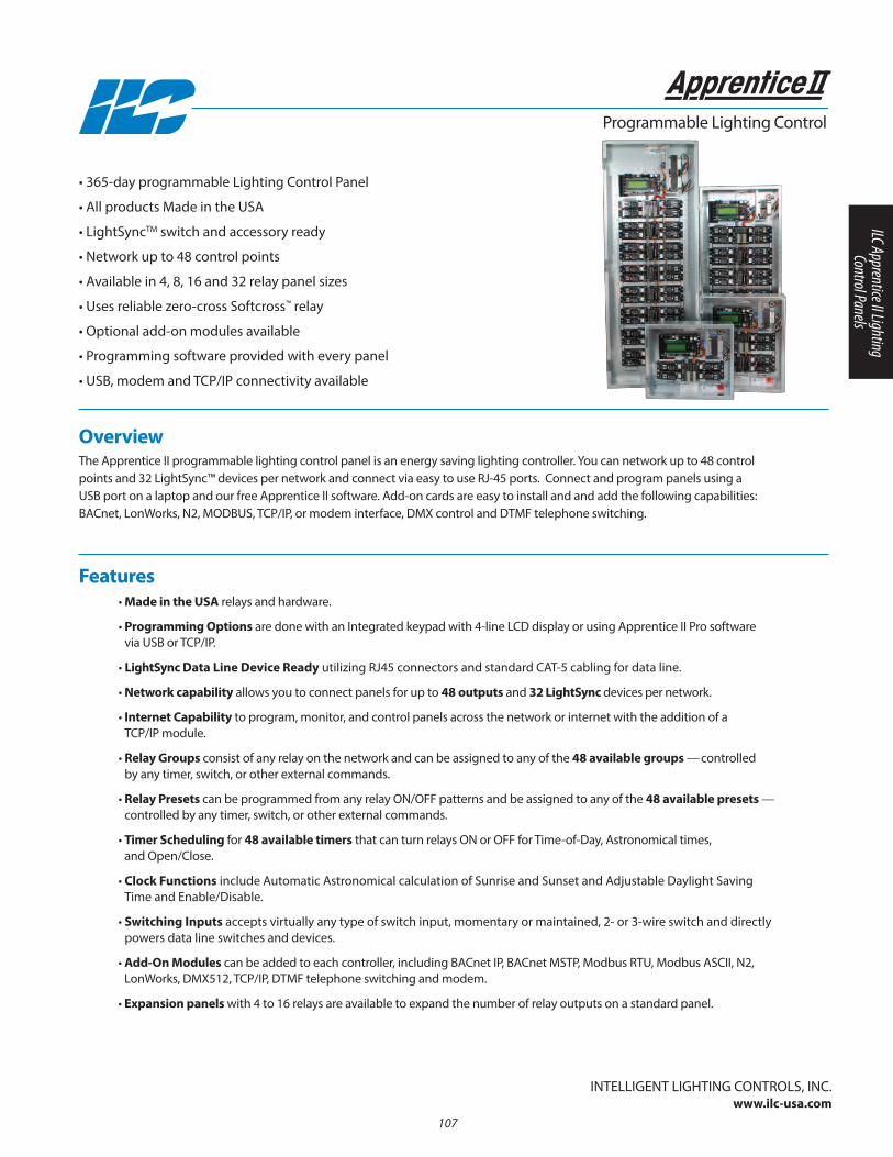
Overview The Apprentice II programmable lighting control panel is an energy saving lighting controller. you can network up to 48 controlpoints and 32 LightSync™ devices per network and connect via easy to use RJ-45 ports. Connect and program panels using a USB port on a laptop and our free Apprentice II software. Add-on cards are easy to install and and add the following capabilities: BACnet, LonWorks, n2, MODBUS, TCP/IP, or modem interface, DMX control and DTMF telephone switching.
• 365-day programmable Lighting Control Panel
• All products Made in the USA
• LightSyncTM switch and accessory ready
• network up to 48 control points
• Available in 4, 8, 16 and 32 relay panel sizes
• Uses reliable zero-cross Softcross™ relay
• Optional add-on modules available
• Programming software provided with every panel
• USB, modem and TCP/IP connectivity available
Programmable Lighting Control
• Made in the USA relays and hardware.
• Programming Options are done with an Integrated keypad with 4-line LCD display or using Apprentice II Pro software via USB or TCP/IP.
• LightSync Data Line Device Ready utilizing RJ45 connectors and standard CAT-5 cabling for data line.
• Network capability allows you to connect panels for up to 48 outputs and 32 LightSync devices per network.
• Internet Capability to program, monitor, and control panels across the network or internet with the addition of a TCP/IP module.
• Relay Groups consist of any relay on the network and can be assigned to any of the 48 available groups —controlled by any timer, switch, or other external commands.
• Relay Presets can be programmed from any relay On/OFF patterns and be assigned to any of the 48 available presets —controlled by any timer, switch, or other external commands.
• Timer Scheduling for 48 available timers that can turn relays On or OFF for Time-of-Day, Astronomical times, and Open/Close.
• Clock Functions include Automatic Astronomical calculation of Sunrise and Sunset and Adjustable Daylight Saving Time and Enable/Disable.
• Switching Inputs accepts virtually any type of switch input, momentary or maintained, 2- or 3-wire switch and directlypowers data line switches and devices.
• Add-On Modules can be added to each controller, including BACnet IP, BACnet MSTP, Modbus RTU, Modbus ASCII, n2, LonWorks, DMX512, TCP/IP, DTMF telephone switching and modem.
• Expansion panels with 4 to 16 relays are available to expand the number of relay outputs on a standard panel.
Features
InTELLIGEnT LIGHTInG COnTROLS, InC.www.ilc-usa.com
107
ILC Apprentice II Lighting Control Panels
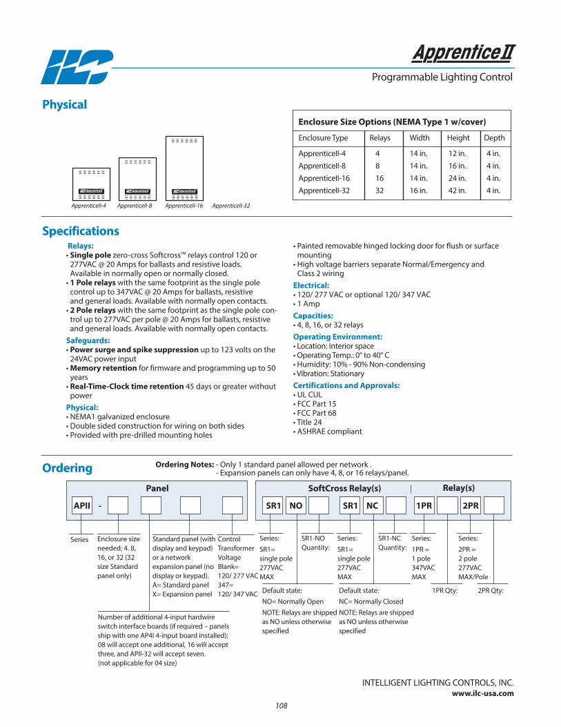
108
Enclosure Size Options (NEMA Type 1 w/cover)
Enclosure Type Relays Width Height Depth
ApprenticeII-4 4 14 in. 12 in. 4 in.ApprenticeII-8 8 14 in. 16 in. 4 in.ApprenticeII-16 16 14 in. 24 in. 4 in.ApprenticeII-32 32 16 in. 42 in. 4 in.
Relays:• Single pole zero-cross Softcross™ relays control 120 or
277VAC @ 20 Amps for ballasts and resistive loads. Available in normally open or normally closed.
• 1 Pole relays with the same footprint as the single pole control up to 347VAC @ 20 Amps for ballasts, resistiveand general loads. Available with normally open contacts.
• 2 Pole relays with the same footprint as the single pole con-trol up to 277VAC per pole @ 20 Amps for ballasts, resistiveand general loads. Available with normally open contacts.
Safeguards:• Power surge and spike suppression up to 123 volts on the
24VAC power input• Memory retention for firmware and programming up to 50
years • Real-Time-Clock time retention 45 days or greater without
powerPhysical:• nEMA1 galvanized enclosure• Double sided construction for wiring on both sides• Provided with pre-drilled mounting holes
• Painted removable hinged locking door for flush or surfacemounting
• High voltage barriers separate normal/Emergency and Class 2 wiring
Electrical:• 120/ 277 VAC or optional 120/ 347 VAC• 1 AmpCapacities:• 4, 8, 16, or 32 relaysOperating Environment:• Location: Interior space• Operating Temp.: 0° to 40° C • Humidity: 10% - 90% non-condensing • Vibration: StationaryCertifications and Approvals:• UL CUL• FCC Part 15• FCC Part 68• Title 24• ASHRAE compliant
Ordering
Programmable Lighting Control
Enclosure sizeneeded; 4. 8,16, or 32 (32size Standardpanel only)
Series
number of additional 4-input hardwireswitch interface boards (if required – panelsship with one AP4I 4-input board installed);08 will accept one additional, 16 will acceptthree, and APII-32 will accept seven.(not applicable for 04 size)
Default state: nO= normally Open nOTE: Relays are shippedas nO unless otherwisespecified
Series:SR1= single pole277VACMAX
SR1-nOQuantity:
Standard panel (withdisplay and keypad) or a network expansion panel (nodisplay or keypad).A= Standard panelX= Expansion panel
Control TransformerVoltageBlank= 120/ 277 VAC347= 120/ 347 VAC
I N T E L L I G E N T L I G H T I N G C O N T R O L S, I N C. M I N N E A P O L I S, M N 8 0 0 9 2 2 8 0 0 4 I N T E L L I G E N T L I G H T I N G C O N T R O L S, I N C. M I N N E A P O L I S, M N 8 0 0 9 2 2 8 0 0 4 I N T E L L I G E N T L I G H T I N G C O N T R O L S, I N C. M I N N E A P O L I S, M N 8 0 0 9 2 2 8 0 0 4
APII - SR1 NO
Panel SoftCross Relay(s) Relay(s)
Default state: nC= normally Closed nOTE: Relays are shippedas nO unless otherwisespecified
Series:SR1= single pole277VACMAX
SR1-nCQuantity:
SR1 NC
2PR Qty:
Series:2PR = 2 pole277VACMAX/Pole
2PR1PR
Series:1PR = 1 pole347VACMAX
1PR Qty:
ApprenticeII-4 ApprenticeII-8 ApprenticeII-16 ApprenticeII-32
Physical
Specifications
InTELLIGEnT LIGHTInG COnTROLS, InC.www.ilc-usa.com
Ordering Notes: - Only 1 standard panel allowed per network .- Expansion panels can only have 4, 8, or 16 relays/panel.
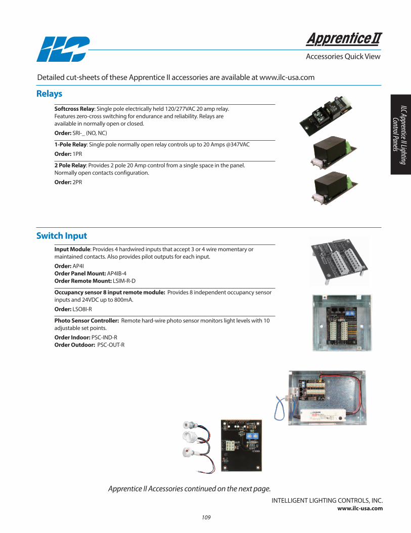
Softcross Relay: Single pole electrically held 120/277VAC 20 amp relay.Features zero-cross switching for endurance and reliability. Relays areavailable in normally open or closed.
Order: SRI-_ (nO, nC)
1-Pole Relay: Single pole normally open relay controls up to 20 Amps @347VAC
Order: 1PR
2 Pole Relay: Provides 2 pole 20 Amp control from a single space in the panel. normally open contacts configuration.
Order: 2PR
Accessories Quick View
Detailed cut-sheets of these Apprentice II accessories are available at www.ilc-usa.com
Apprentice II Accessories continued on the next page.
Relays
Switch Input
InTELLIGEnT LIGHTInG COnTROLS, InC.www.ilc-usa.com
109
Input Module: Provides 4 hardwired inputs that accept 3 or 4 wire momentary or maintained contacts. Also provides pilot outputs for each input.
Order: AP4IOrder Panel Mount: AP4IB-4Order Remote Mount: LSIM-R-D
Occupancy sensor 8 input remote module: Provides 8 independent occupancy sensorinputs and 24VDC up to 800mA.
Order: LSO8I-R
Photo Sensor Controller: Remote hard-wire photo sensor monitors light levels with 10adjustable set points.
Order Indoor: PSC-InD-ROrder Outdoor: PSC-OUT-R
ILC Apprentice II Lighting Control Panels
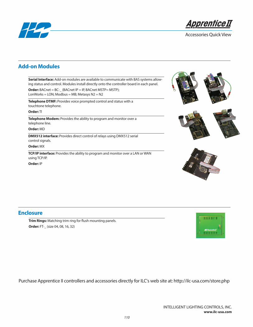
110
Accessories Quick View
InTELLIGEnT LIGHTInG COnTROLS, InC.www.ilc-usa.com
Purchase Apprentice II controllers and accessories directly for ILC's web site at: http://ilc-usa.com/store.php
Add-on Modules
Enclosure
Serial Interface: Add-on modules are available to communicate with BAS systems allow-ing status and control. Modules install directly onto the controller board in each panel.
Order: BACnet = BC-_ (BACnet IP = IP, BACnet MSTP= MSTP); LonWorks = LOn; Modbus = MB; Metasys n2 = n2
Telephone DTMF: Provides voice prompted control and status with a touchtone telephone.
Order: Tl
Telephone Modem: Provides the ability to program and monitor over a telephone line.
Order: MD
DMX512 interface: Provides direct control of relays using DMX512 serial control signals.
Order: MX
TCP/IP interface: Provides the ability to program and monitor over a LAn or WAn using TCP/IP.
Order: IP
Trim Rings: Matching trim ring for flush mounting panels.
Order: FT-_ (size 04, 08, 16, 32)

Section 9: Relays
• Reliant 40 Relays
• Emergency Power Control
111
Relays

112
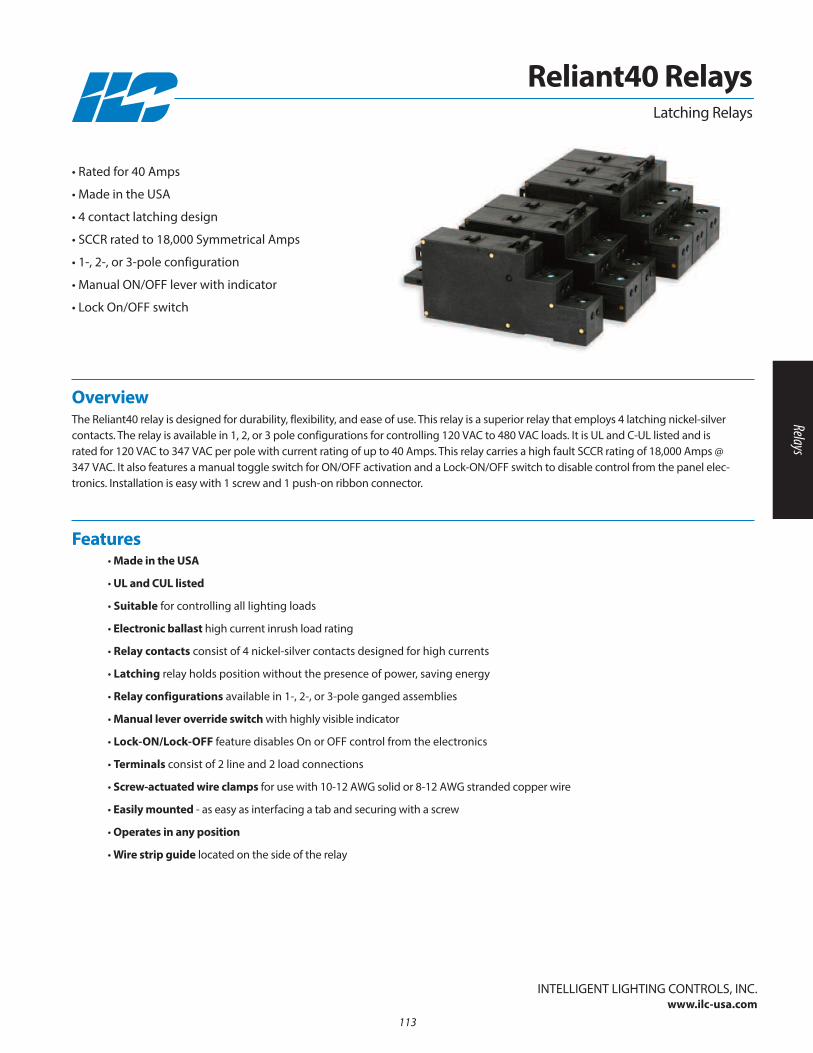
• Made in the USA
• UL and CUL listed
• Suitable for controlling all lighting loads
• Electronic ballast high current inrush load rating
• Relay contacts consist of 4 nickel-silver contacts designed for high currents
• Latching relay holds position without the presence of power, saving energy
• Relay configurations available in 1-, 2-, or 3-pole ganged assemblies
• Manual lever override switch with highly visible indicator
• Lock-ON/Lock-OFF feature disables On or OFF control from the electronics
• Terminals consist of 2 line and 2 load connections
• Screw-actuated wire clamps for use with 10-12 AWG solid or 8-12 AWG stranded copper wire
• Easily mounted - as easy as interfacing a tab and securing with a screw
• Operates in any position
• Wire strip guide located on the side of the relay
Features
Overview The Reliant40 relay is designed for durability, flexibility, and ease of use. This relay is a superior relay that employs 4 latching nickel-silvercontacts. The relay is available in 1, 2, or 3 pole configurations for controlling 120 VAC to 480 VAC loads. It is UL and C-UL listed and israted for 120 VAC to 347 VAC per pole with current rating of up to 40 Amps. This relay carries a high fault SCCR rating of 18,000 Amps @347 VAC. It also features a manual toggle switch for On/OFF activation and a Lock-On/OFF switch to disable control from the panel elec-tronics. Installation is easy with 1 screw and 1 push-on ribbon connector.
• Rated for 40 Amps
• Made in the USA
• 4 contact latching design
• SCCR rated to 18,000 Symmetrical Amps
• 1-, 2-, or 3-pole configuration
• Manual On/OFF lever with indicator
• Lock On/OFF switch
InTELLIGEnT LIGHTInG COnTROLS, InC.www.ilc-usa.com
Reliant40 RelaysLatching Relays
113
Relays
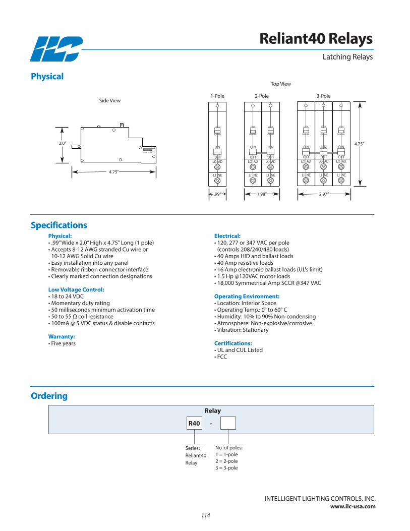
Side View
Top View
1-Pole 2-Pole 3-Pole
4.75”
2.97”
4.75”
1.98”.99”
Physical:• .99” Wide x 2.0” High x 4.75” Long (1 pole)• Accepts 8-12 AWG stranded Cu wire or
10-12 AWG Solid Cu wire• Easy installation into any panel• Removable ribbon connector interface• Clearly marked connection designations
Low Voltage Control:• 18 to 24 VDC • Momentary duty rating• 50 milliseconds minimum activation time • 50 to 55 Ω coil resistance• 100mA @ 5 VDC status & disable contacts
Warranty:• Five years
Electrical:• 120, 277 or 347 VAC per pole
(controls 208/240/480 loads)• 40 Amps HID and ballast loads• 40 Amp resistive loads• 16 Amp electronic ballast loads (UL's limit)• 1.5 Hp @120VAC motor loads• 18,000 Symmetrical Amp SCCR @347 VAC
Operating Environment:• Location: Interior Space• Operating Temp.: 0° to 60° C • Humidity: 10% to 90% non-condensing • Atmosphere: non-explosive/corrosive• Vibration: Stationary
Certifications:• UL and CUL Listed• FCC
Ordering
no. of poles:1 = 1-pole2 = 2-pole3 = 3-pole
Series: Reliant40 Relay
Relay
Specifications
InTELLIGEnT LIGHTInG COnTROLS, InC.www.ilc-usa.com
Reliant40 Relays
R40 -
Physical
Latching Relays
2.0”
114
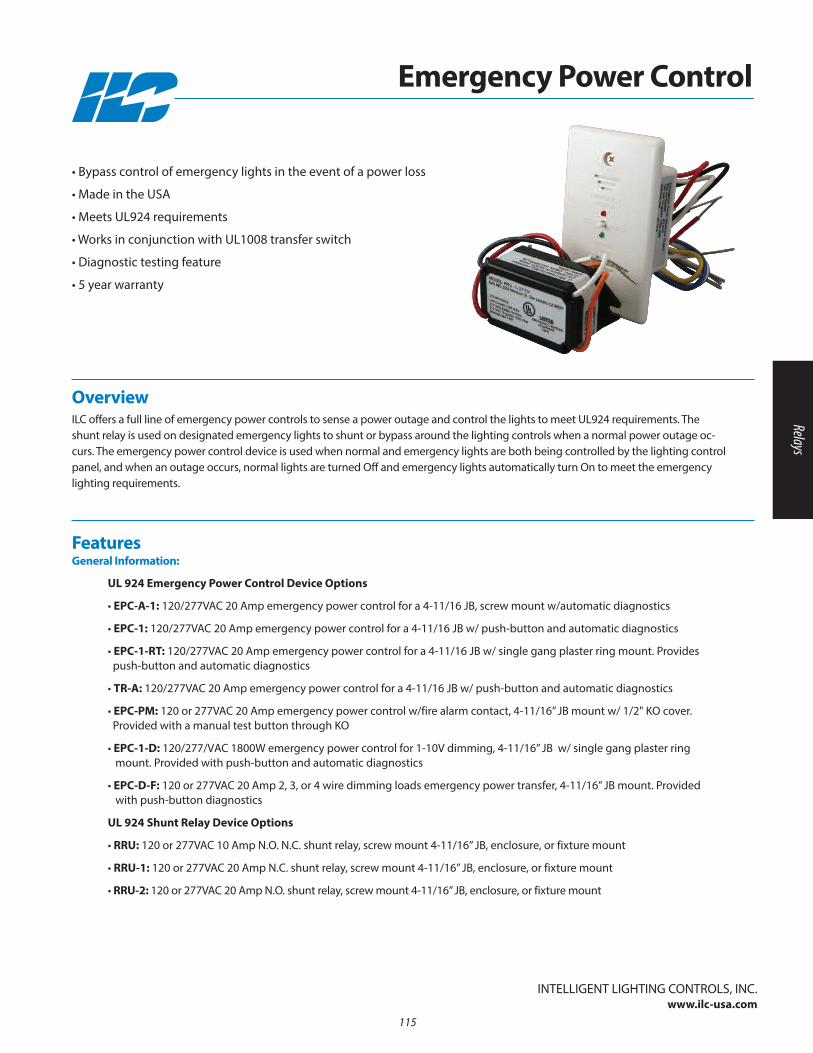
UL 924 Emergency Power Control Device Options
• EPC-A-1: 120/277VAC 20 Amp emergency power control for a 4-11/16 JB, screw mount w/automatic diagnostics
• EPC-1: 120/277VAC 20 Amp emergency power control for a 4-11/16 JB w/ push-button and automatic diagnostics
• EPC-1-RT: 120/277VAC 20 Amp emergency power control for a 4-11/16 JB w/ single gang plaster ring mount. Provides push-button and automatic diagnostics
• TR-A: 120/277VAC 20 Amp emergency power control for a 4-11/16 JB w/ push-button and automatic diagnostics
• EPC-PM: 120 or 277VAC 20 Amp emergency power control w/fire alarm contact, 4-11/16” JB mount w/ 1/2" KO cover. Provided with a manual test button through KO
• EPC-1-D: 120/277/VAC 1800W emergency power control for 1-10V dimming, 4-11/16” JB w/ single gang plaster ring mount. Provided with push-button and automatic diagnostics
• EPC-D-F: 120 or 277VAC 20 Amp 2, 3, or 4 wire dimming loads emergency power transfer, 4-11/16” JB mount. Providedwith push-button diagnostics
UL 924 Shunt Relay Device Options
• RRU: 120 or 277VAC 10 Amp n.O. n.C. shunt relay, screw mount 4-11/16” JB, enclosure, or fixture mount
• RRU-1: 120 or 277VAC 20 Amp n.C. shunt relay, screw mount 4-11/16” JB, enclosure, or fixture mount
• RRU-2: 120 or 277VAC 20 Amp n.O. shunt relay, screw mount 4-11/16” JB, enclosure, or fixture mount
FeaturesGeneral Information:
Overview ILC offers a full line of emergency power controls to sense a power outage and control the lights to meet UL924 requirements. Theshunt relay is used on designated emergency lights to shunt or bypass around the lighting controls when a normal power outage oc-curs. The emergency power control device is used when normal and emergency lights are both being controlled by the lighting controlpanel, and when an outage occurs, normal lights are turned Off and emergency lights automatically turn On to meet the emergencylighting requirements.
• Bypass control of emergency lights in the event of a power loss
• Made in the USA
• Meets UL924 requirements
• Works in conjunction with UL1008 transfer switch
• Diagnostic testing feature
• 5 year warranty
InTELLIGEnT LIGHTInG COnTROLS, InC.www.ilc-usa.com
Emergency Power Control
115
Relays
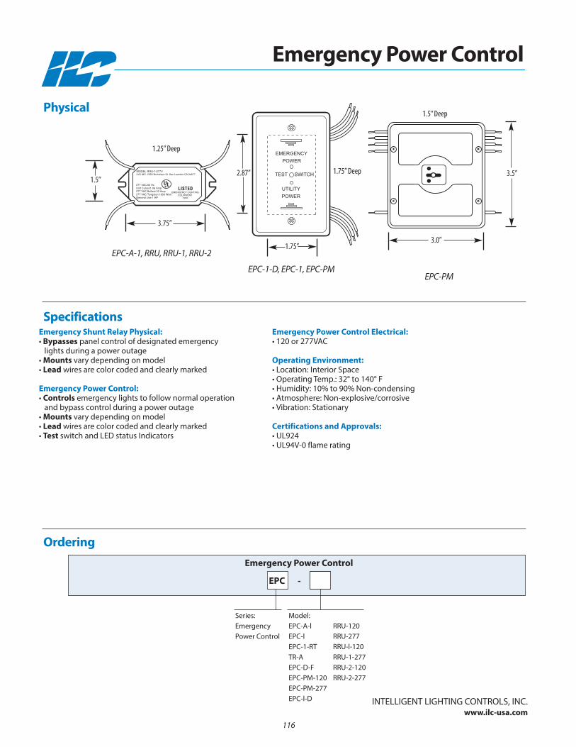
Emergency Shunt Relay Physical:• Bypasses panel control of designated emergency
lights during a power outage• Mounts vary depending on model• Lead wires are color coded and clearly marked
Emergency Power Control:• Controls emergency lights to follow normal operation
and bypass control during a power outage• Mounts vary depending on model• Lead wires are color coded and clearly marked• Test switch and LED status Indicators
Emergency Power Control Electrical:• 120 or 277VAC
Operating Environment:• Location: Interior Space• Operating Temp.: 32° to 140° F • Humidity: 10% to 90% non-condensing • Atmosphere: non-explosive/corrosive• Vibration: Stationary
Certifications and Approvals:• UL924• UL94V-0 flame rating
Ordering
RRU-120RRU-277RRU-l-120RRU-1-277RRU-2-120RRU-2-277
Model: EPC-A-lEPC-lEPC-1-RTTR-AEPC-D-FEPC-PM-120EPC-PM-277EPC-l-D
Emergency Power Control
Series: Emergency Power Control
Specifications
InTELLIGEnT LIGHTInG COnTROLS, InC.www.ilc-usa.com
Emergency Power Control
EPC -
Physical
EPC-A-1, RRU, RRU-1, RRU-2
EPC-1-D, EPC-1, EPC-PMEPC-PM
1.5”
3.75”
2.87” 3.5”
1.25” Deep
1.75” Deep
1.5” Deep
3.0”1.75”
116
EMERGENCY
POWER
TEST SWITCH
UTILITY
POWER
LISTEDEMERGENCY LIGHTING
EQUIPMENT73PK
MODEL RRU-1-277VLVS INC. 2555 Nicholson St. San Leandro CA 94577
277 VAC 60 HzUnit Current .06 Amp277 VAC Ballast 20 Amp277 VAC Tungsten 1800 WattGeneral Use 1 HP

Section 10: Software and Computers
• LightLEEDer Pro
• LightLEEDer InSite
• LightLEEDer Runtime Pro
• Factory Supplied Computers
117
Software and Computers

118
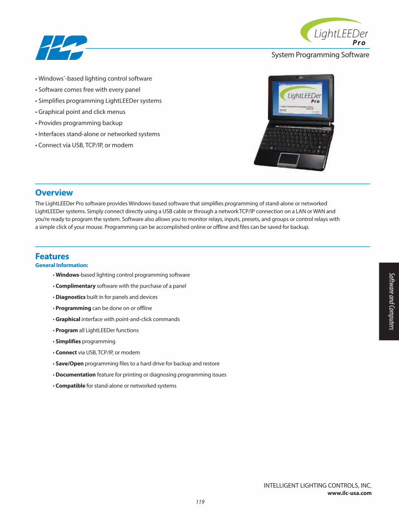
System Programming Software
Overview The LightLEEDer Pro software provides Windows-based software that simplifies programming of stand-alone or networkedLightLEEDer systems. Simply connect directly using a USB cable or through a network TCP/IP connection on a LAn or WAn and you’re ready to program the system. Software also allows you to monitor relays, inputs, presets, and groups or control relays with a simple click of your mouse. Programming can be accomplished online or offline and files can be saved for backup.
• Windows®-based lighting control software
• Software comes free with every panel
• Simplifies programming LightLEEDer systems
• Graphical point and click menus
• Provides programming backup
• Interfaces stand-alone or networked systems
• Connect via USB, TCP/IP, or modem
Features General Information:
• Windows-based lighting control programming software
• Complimentary software with the purchase of a panel
• Diagnostics built in for panels and devices
• Programming can be done on or offline
• Graphical interface with point-and-click commands
• Program all LightLEEDer functions
• Simplifies programming
• Connect via USB, TCP/IP, or modem
• Save/Open programming files to a hard drive for backup and restore
• Documentation feature for printing or diagnosing programming issues
• Compatible for stand-alone or networked systems
InTELLIGEnT LIGHTInG COnTROLS, InC.www.ilc-usa.com
119
Software and Computers
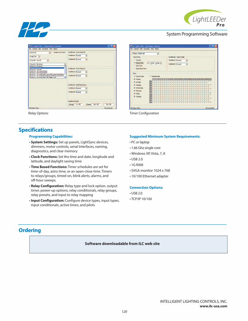
Programming Capabilities:
• System Settings: Set up panels, LightSync devices, dimmers, motor controls, serial Interfaces, naming, diagnostics, and clear memory
• Clock Functions: Set the time and date, longitude and latitude, and daylight saving time
• Time Based Functions: Timer schedules are set for time-of-day, astro time, or an open-close time. Timers to relays/groups, timed-on, blink alerts, alarms, and off-hour sweeps.
• Relay Configuration: Relay type and lock option, outputtimer, power-up options, relay conditionals, relay groups, relay presets, and input to relay mapping
• Input Configuration: Configure device types, input types,input conditionals, active times, and pilots
Suggested Minimum System Requirements:
• PC or laptop
• 1.66 Ghz single core
• Windows XP, Vista, 7, 8
• USB 2.0
• 1G RAM
• SVGA monitor 1024 x 768
• 10/100 Ethernet adapter
Connection Options:
• USB 2.0
• TCP/IP 10/100
Ordering
System Programming Software
Software downloadable from ILC web site
Specifications
InTELLIGEnT LIGHTInG COnTROLS, InC.www.ilc-usa.com
Relay Options Timer Configuration
120
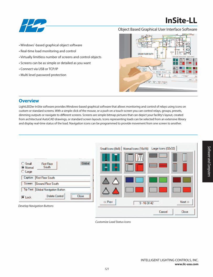
Overview LightLEEDer InSite software provides Windows-based graphical software that allows monitoring and control of relays using icons oncustom or standard screens. With a simple click of the mouse, or a push on a touch-screen you can control relays, groups, presets, dimming outputs or navigate to different screens. Screens are simple bitmap pictures that can depict your facility's layout, createdfrom architectural AutoCAD drawings, or standard screen layouts. Icons representing loads can be selected from an extensive libraryand display real-time status of the load. navigation icons can be programmed to provide movement from one screen to another.
• Windows®-based graphical object software
• Real-time load monitoring and control
• Virtually limitless number of screens and control objects
• Screens can be as simple or detailed as you want
• Connect via USB or TCP/IP
• Multi level password protection
InTELLIGEnT LIGHTInG COnTROLS, InC.www.ilc-usa.com
InSite-LL
Customize Load Status Icons
Object Based Graphical User Interface Software
121
Develop Navigation Buttons
Software and Computers
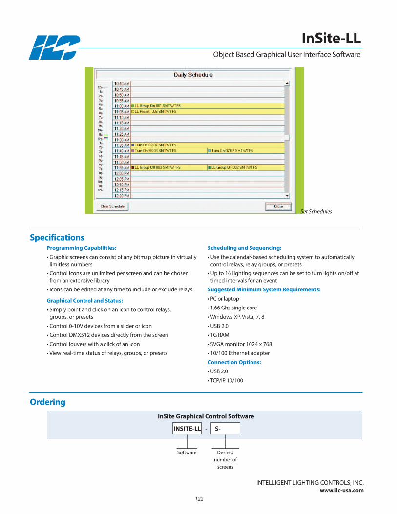
Ordering
Software
InSite Graphical Control Software
InTELLIGEnT LIGHTInG COnTROLS, InC.www.ilc-usa.com
InSite-LL
INSITE-LL
Desirednumber of
screens
S--
Programming Capabilities:
• Graphic screens can consist of any bitmap picture in virtuallylimitless numbers
• Control icons are unlimited per screen and can be chosen from an extensive library
• Icons can be edited at any time to include or exclude relays
Graphical Control and Status:
• Simply point and click on an icon to control relays, groups, or presets
• Control 0-10V devices from a slider or icon
• Control DMX512 devices directly from the screen
• Control louvers with a click of an icon
• View real-time status of relays, groups, or presets
Scheduling and Sequencing:
• Use the calendar-based scheduling system to automaticallycontrol relays, relay groups, or presets
• Up to 16 lighting sequences can be set to turn lights on/off attimed intervals for an event
Suggested Minimum System Requirements:
• PC or laptop
• 1.66 Ghz single core
• Windows XP, Vista, 7, 8
• USB 2.0
• 1G RAM
• SVGA monitor 1024 x 768
• 10/100 Ethernet adapter
Connection Options:
• USB 2.0
• TCP/IP 10/100
Specifications
Object Based Graphical User Interface Software
122
Set Schedules

System Runtime and Trending Software
Overview LightLEEDer Runtime Pro software is a Windows-based software that harvests and documents runtime and trending data of loads instand-alone or networked LightLEEDer systems. Simply connect directly using a USB cable or through a network TCP/IP connectionfrom your LAn or WAn and you’re ready to compile data from the LightLEEDer system. Data harvested can be recorded for single orcombined groups of relays. This data can be displayed as a spreadsheet report or in a graph form for daily or monthly usage. Reportsare able to be directly exported to a comma separated value file that can be opened in Excel. Live usage wattage meters are availablefor displaying single or combined relays.
Features General Information:
• Windows-based Runtime and Trending software
• Harvest data directly from lighting controllers
• Records load states, photocell and dimming levels
• Graphical interface with point-and-click commands
• Connect using USB or TCP/IP
• Runtime recorded to the minute
• Trending generates a graphical chart of On and OFF times
• Wattage settings for each relay
• Export data into a spreadsheet
• Print data directly from graph screen
• Compatible for stand-alone or networked systems
InTELLIGEnT LIGHTInG COnTROLS, InC.www.ilc-usa.com
• Windows®-based Runtime and Trending software
• Harvests data from lighting controllers
• Converts runtime to wattage used
• Monitors photocell and dimming levels
• Graphical point and click menus
• Connect via USB or TCP/IP
• Live usage wattage meters
123
Software and Computers
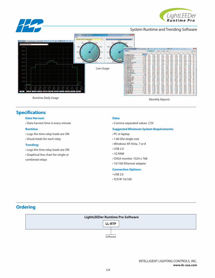
Data Harvest:
• Data harvest time is every minute
Runtime:
• Logs the time relay loads are On
• Visual totals for each relay
Trending:
• Logs the time relay loads are On
• Graphical line chart for single or
combined relays
Data:
• Comma separated values .CSV
Suggested Minimum System Requirements:
• PC or laptop
• 1.66 Ghz single core
• Windows XP, Vista, 7 or 8
• USB 2.0
• 1G RAM
• SVGA monitor 1024 x 768
• 10/100 Ethernet adapter
Connection Options:
• USB 2.0
• TCP/IP 10/100
System Runtime and Trending Software
Specifications
InTELLIGEnT LIGHTInG COnTROLS, InC.www.ilc-usa.com
Ordering
Software
LightLEEDer Runtime Pro Software
LL-RTP
124
Runtime Daily Usage
Live Usage
Monthly Reports
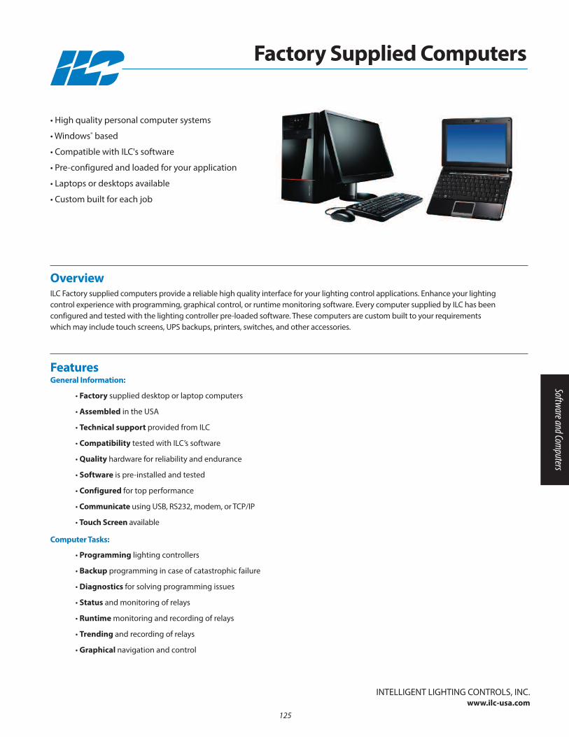
• Factory supplied desktop or laptop computers
• Assembled in the USA
• Technical support provided from ILC
• Compatibility tested with ILC’s software
• Quality hardware for reliability and endurance
• Software is pre-installed and tested
• Configured for top performance
• Communicate using USB, RS232, modem, or TCP/IP
• Touch Screen available
FeaturesGeneral Information:
• Programming lighting controllers
• Backup programming in case of catastrophic failure
• Diagnostics for solving programming issues
• Status and monitoring of relays
• Runtime monitoring and recording of relays
• Trending and recording of relays
• Graphical navigation and control
Computer Tasks:
Overview ILC Factory supplied computers provide a reliable high quality interface for your lighting control applications. Enhance your lightingcontrol experience with programming, graphical control, or runtime monitoring software. Every computer supplied by ILC has beenconfigured and tested with the lighting controller pre-loaded software. These computers are custom built to your requirementswhich may include touch screens, UPS backups, printers, switches, and other accessories.
• High quality personal computer systems
• Windows® based
• Compatible with ILC's software
• Pre-configured and loaded for your application
• Laptops or desktops available
• Custom built for each job
InTELLIGEnT LIGHTInG COnTROLS, InC.www.ilc-usa.com
Factory Supplied Computers
125
Software and Computers

126
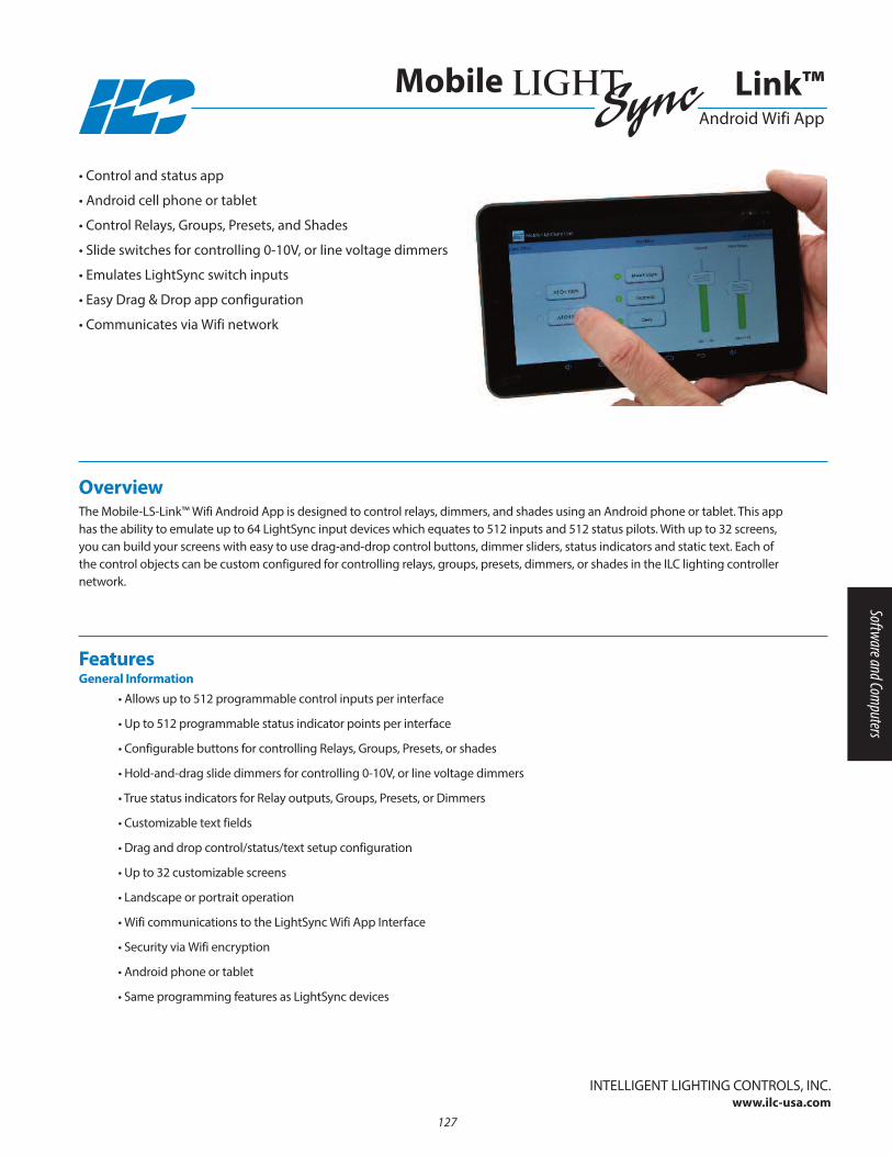
InTELLIGEnT LIGHTInG COnTROLS, InC.www.ilc-usa.com
127
Overview The Mobile-LS-Link™ Wifi Android App is designed to control relays, dimmers, and shades using an Android phone or tablet. This apphas the ability to emulate up to 64 LightSync input devices which equates to 512 inputs and 512 status pilots. With up to 32 screens,you can build your screens with easy to use drag-and-drop control buttons, dimmer sliders, status indicators and static text. Each ofthe control objects can be custom configured for controlling relays, groups, presets, dimmers, or shades in the ILC lighting controllernetwork.
• Control and status app
• Android cell phone or tablet
• Control Relays, Groups, Presets, and Shades
• Slide switches for controlling 0-10V, or line voltage dimmers
• Emulates LightSync switch inputs
• Easy Drag & Drop app configuration
• Communicates via Wifi network
• Allows up to 512 programmable control inputs per interface
• Up to 512 programmable status indicator points per interface
• Configurable buttons for controlling Relays, Groups, Presets, or shades
• Hold-and-drag slide dimmers for controlling 0-10V, or line voltage dimmers
• True status indicators for Relay outputs, Groups, Presets, or Dimmers
• Customizable text fields
• Drag and drop control/status/text setup configuration
• Up to 32 customizable screens
• Landscape or portrait operation
• Wifi communications to the LightSync Wifi App Interface
• Security via Wifi encryption
• Android phone or tablet
• Same programming features as LightSync devices
FeaturesGeneral Information
Link™ Android Wifi App
Mobile
Software and Computers
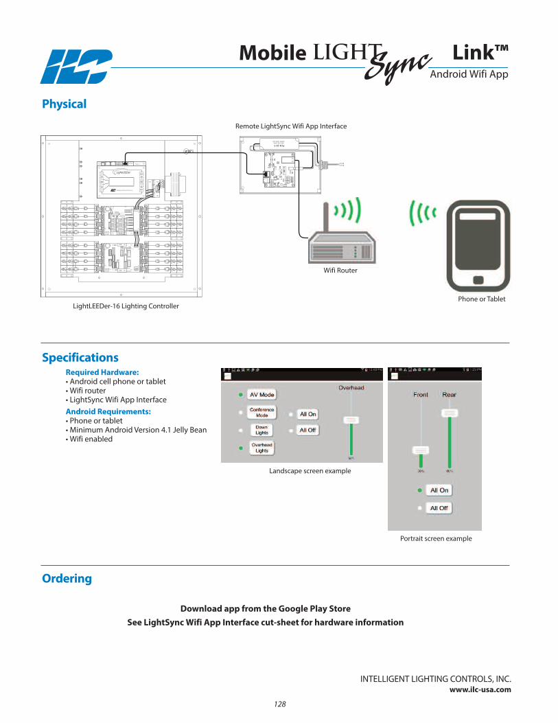
InTELLIGEnT LIGHTInG COnTROLS, InC.www.ilc-usa.com
128
ALL OFFOFF ON
POWER
77013490 R1
ALL ON
POWER
24VAC CT
24VAC CT
77013488A
97013488
POWER
24VAC CT
24VAC CT
77013488A
97013488
1 ON
1 PILOT
1 OFF
1 COM
3 ON
3 OFF
3 COM
3 PILOT
2 ON
2 PILOT
2 OFF
2 COM
4 ON
4 OFF
4 COM
EXT +V
EXTCOM
4 PILOT
OUTIN
77013485A
Intelligent Lighting Controls, Inc.
PLN-20-5
5
Link™ Android Wifi App
Mobile
Required Hardware:• Android cell phone or tablet• Wifi router• LightSync Wifi App InterfaceAndroid Requirements:• Phone or tablet• Minimum Android Version 4.1 Jelly Bean• Wifi enabled
Physical
Specifications
Ordering
Download app from the Google Play StoreSee LightSync Wifi App Interface cut-sheet for hardware information
Remote LightSync Wifi App Interface
LightLEEDer-16 Lighting Controller
Wifi Router
Portrait screen example
Landscape screen example
Phone or Tablet
Section 11: Hardwired Switch Stations
• Touch Activated Graphic Control Stations
• LightSync Touch Screen Station
• nFP Series Switch Stations
• Wet or Wash-Down Location Touch Switch
• Security Touch Switch
• Heavy Duty Switch Stations
• Key Switch Stations
• Custom and Graphic Switch Stations
• Hinged Locking Door Switch Station
129
Hardwired Switch Stations

130

• Touch activated switch station
• Screens are available in sizes from 3.5” to 17”
• High resolution color screens
• Bright screens are easily seen
• Network ready with built in communications
• USB port for back up of programming
• Configured at the factory for easy installation
• Fan-less design for quiet operation
• Security can be enabled to limit access
• Graphics software installed
• Custom enclosures are available as required
FeaturesGeneral Information:
Overview Touch Activated Graphic Control Stations provide the ultimate in graphics and control. These panel touch screens have an integrated touch sensor screen and are designed to be either flush or console mounted. They come equipped with communications connectionsthat communicate directly to the lighting panels. With the use of graphical icons, you can control anything from a single story officespace to the most complex control requirements imaginable. Through the use of high resolution graphics and programmed control objects, users can easily develop meaningful graphic control screens that enhance and simplify the control of any facility.
• Touch activated switch station
• Available with screens from 3.5” to 17”
• High resolution color screens
• Communicates directly with lighting panels
InTELLIGEnT LIGHTInG COnTROLS, InC.www.ilc-usa.com
Touch Activated Graphic Control Stations
131
Hardwired Switch Stations
Ordering
Contact ILC for Ordering Details
Physical
InTELLIGEnT LIGHTInG COnTROLS, InC.www.ilc-usa.com
Touch Activated Graphic Control Stations
Physical:• Contact ILCElectrical:• 120 VAC
Operating Environment:• Location: Interior space• Operating Temp.: 0° to 50° C • Humidity: 10% - 90% non-condensing • Atmosphere: non-explosive/corrosive • Vibration: Stationary application nEMA Level ACertifications and Approvals:• FCC • UL
Specifications
Contact ILC for Specific Physical Details
132
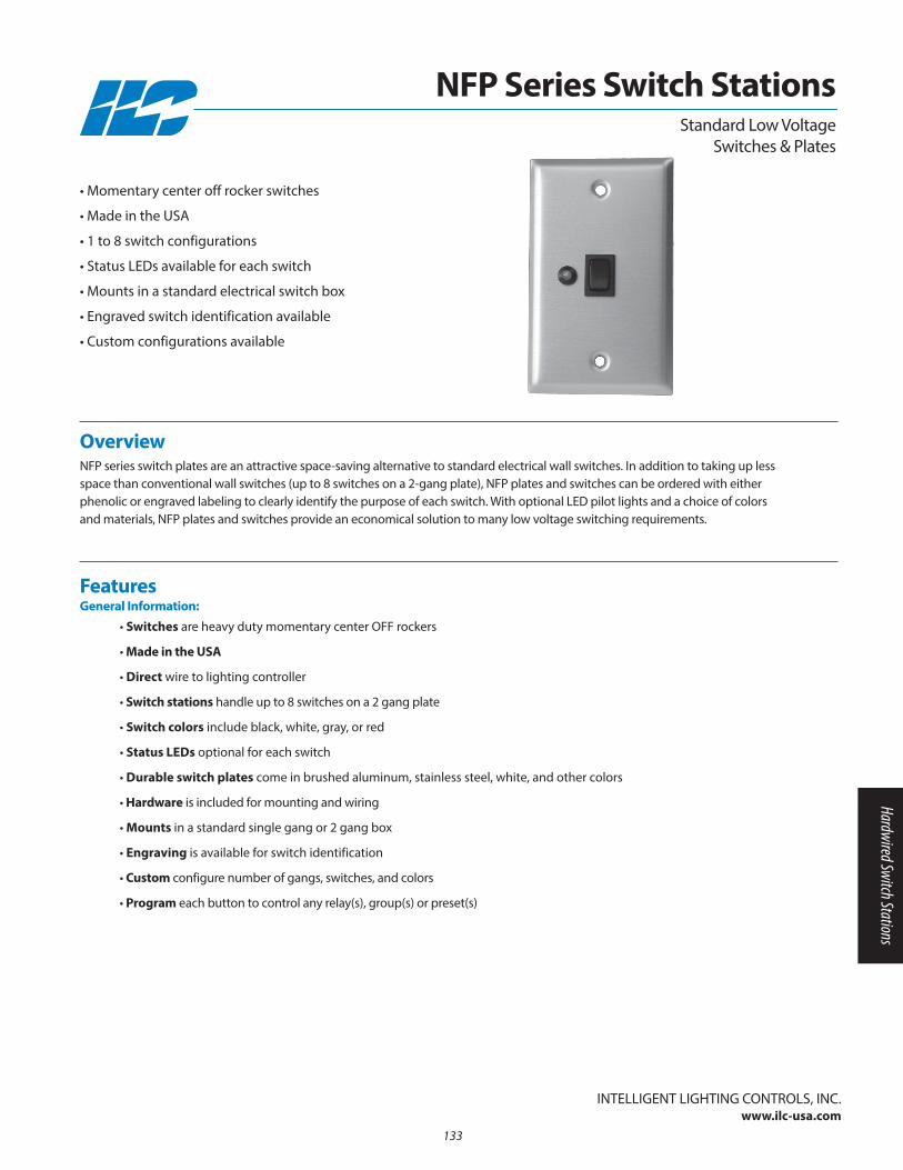
• Switches are heavy duty momentary center OFF rockers
• Made in the USA
• Direct wire to lighting controller
• Switch stations handle up to 8 switches on a 2 gang plate
• Switch colors include black, white, gray, or red
• Status LEDs optional for each switch
• Durable switch plates come in brushed aluminum, stainless steel, white, and other colors
• Hardware is included for mounting and wiring
• Mounts in a standard single gang or 2 gang box
• Engraving is available for switch identification
• Custom configure number of gangs, switches, and colors
• Program each button to control any relay(s), group(s) or preset(s)
Features General Information:
Overview nFP series switch plates are an attractive space-saving alternative to standard electrical wall switches. In addition to taking up lessspace than conventional wall switches (up to 8 switches on a 2-gang plate), nFP plates and switches can be ordered with either phenolic or engraved labeling to clearly identify the purpose of each switch. With optional LED pilot lights and a choice of colors and materials, nFP plates and switches provide an economical solution to many low voltage switching requirements.
• Momentary center off rocker switches
• Made in the USA
• 1 to 8 switch configurations
• Status LEDs available for each switch
• Mounts in a standard electrical switch box
• Engraved switch identification available
• Custom configurations available
InTELLIGEnT LIGHTInG COnTROLS, InC.www.ilc-usa.com
NFP Series Switch StationsStandard Low Voltage
Switches & Plates
133
Hardwired Switch Stations
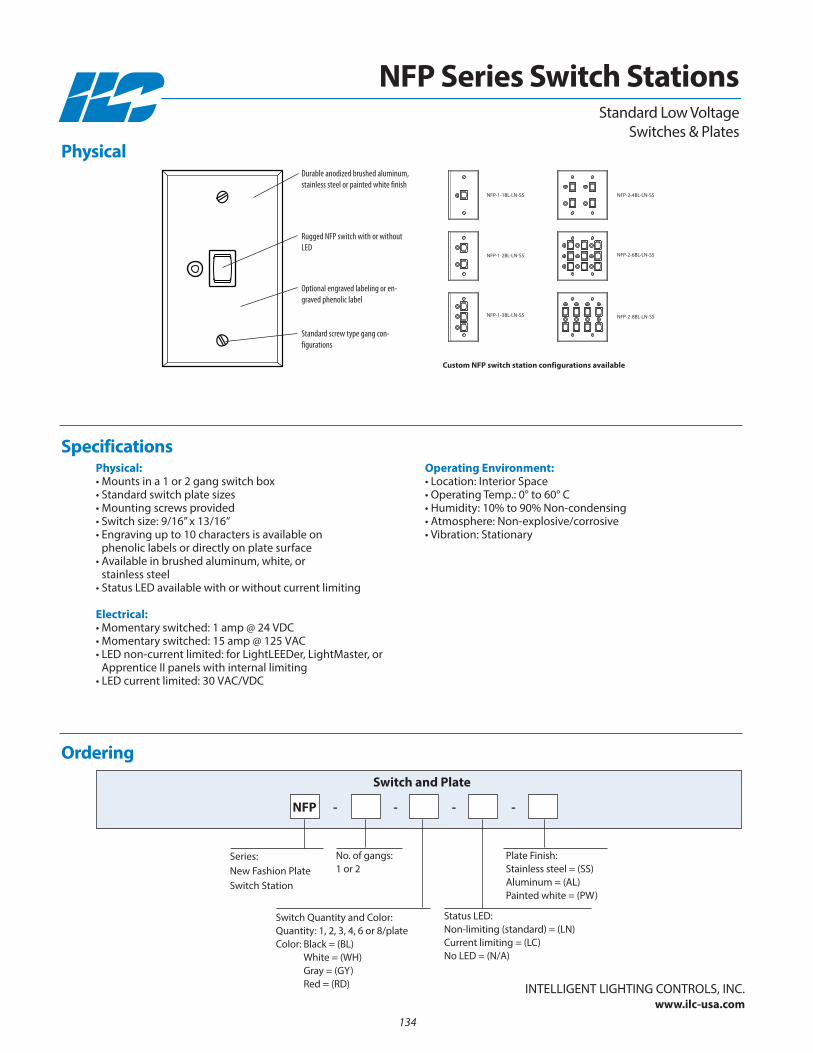
Physical:• Mounts in a 1 or 2 gang switch box• Standard switch plate sizes• Mounting screws provided• Switch size: 9/16” x 13/16”• Engraving up to 10 characters is available on
phenolic labels or directly on plate surface• Available in brushed aluminum, white, or
stainless steel• Status LED available with or without current limiting
Electrical:• Momentary switched: 1 amp @ 24 VDC• Momentary switched: 15 amp @ 125 VAC• LED non-current limited: for LightLEEDer, LightMaster, or
Apprentice II panels with internal limiting• LED current limited: 30 VAC/VDC
Operating Environment:• Location: Interior Space• Operating Temp.: 0° to 60° C • Humidity: 10% to 90% non-condensing • Atmosphere: non-explosive/corrosive• Vibration: Stationary
Ordering
no. of gangs:1 or 2
Series: new Fashion Plate Switch Station
Switch and Plate
Status LED:non-limiting (standard) = (Ln)Current limiting = (LC)no LED = (n/A)
Plate Finish:Stainless steel = (SS)Aluminum = (AL)Painted white = (PW)
Switch Quantity and Color:Quantity: 1, 2, 3, 4, 6 or 8/plateColor: Black = (BL)
White = (WH)Gray = (Gy)Red = (RD)
Specifications
InTELLIGEnT LIGHTInG COnTROLS, InC.www.ilc-usa.com
NFP Series Switch Stations
NFP - - - -
Standard Low VoltageSwitches & Plates
nFP-1-1BL-Ln-SS
nFP-1-2BL-Ln-SS
nFP-1-3BL-Ln-SS
nFP-2-4BL-Ln-SS
nFP-2-6BL-Ln-SS
nFP-2-8BL-Ln-SS
Custom NFP switch station configurations available
Durable anodized brushed aluminum,stainless steel or painted white finish
Rugged NFP switch with or withoutLED
Optional engraved labeling or en-graved phenolic label
Standard screw type gang con-figurations
Physical
134
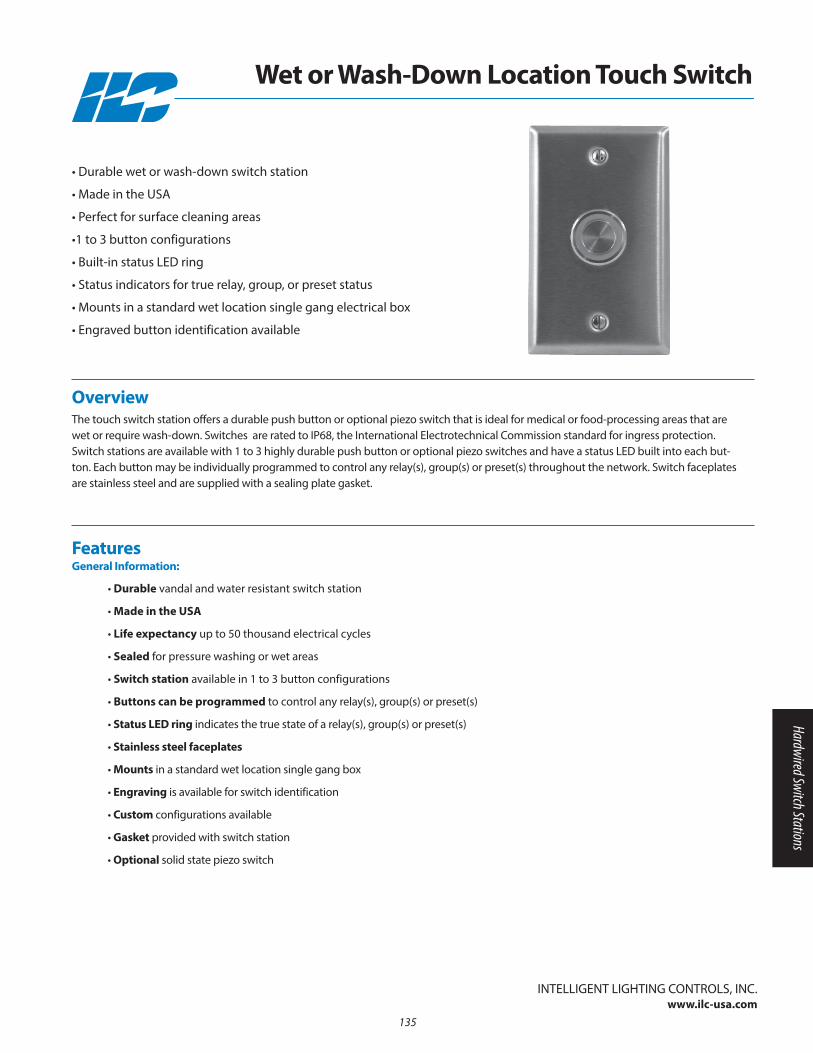
• Durable vandal and water resistant switch station
• Made in the USA
• Life expectancy up to 50 thousand electrical cycles
• Sealed for pressure washing or wet areas
• Switch station available in 1 to 3 button configurations
• Buttons can be programmed to control any relay(s), group(s) or preset(s)
• Status LED ring indicates the true state of a relay(s), group(s) or preset(s)
• Stainless steel faceplates
• Mounts in a standard wet location single gang box
• Engraving is available for switch identification
• Custom configurations available
• Gasket provided with switch station
• Optional solid state piezo switch
FeaturesGeneral Information:
Overview The touch switch station offers a durable push button or optional piezo switch that is ideal for medical or food-processing areas that arewet or require wash-down. Switches are rated to IP68, the International Electrotechnical Commission standard for ingress protection.Switch stations are available with 1 to 3 highly durable push button or optional piezo switches and have a status LED built into each but-ton. Each button may be individually programmed to control any relay(s), group(s) or preset(s) throughout the network. Switch faceplatesare stainless steel and are supplied with a sealing plate gasket.
• Durable wet or wash-down switch station
• Made in the USA
• Perfect for surface cleaning areas
•1 to 3 button configurations
• Built-in status LED ring
• Status indicators for true relay, group, or preset status
• Mounts in a standard wet location single gang electrical box
• Engraved button identification available
InTELLIGEnT LIGHTInG COnTROLS, InC.www.ilc-usa.com
Wet or Wash-Down Location Touch Switch
135
Hardwired Switch Stations
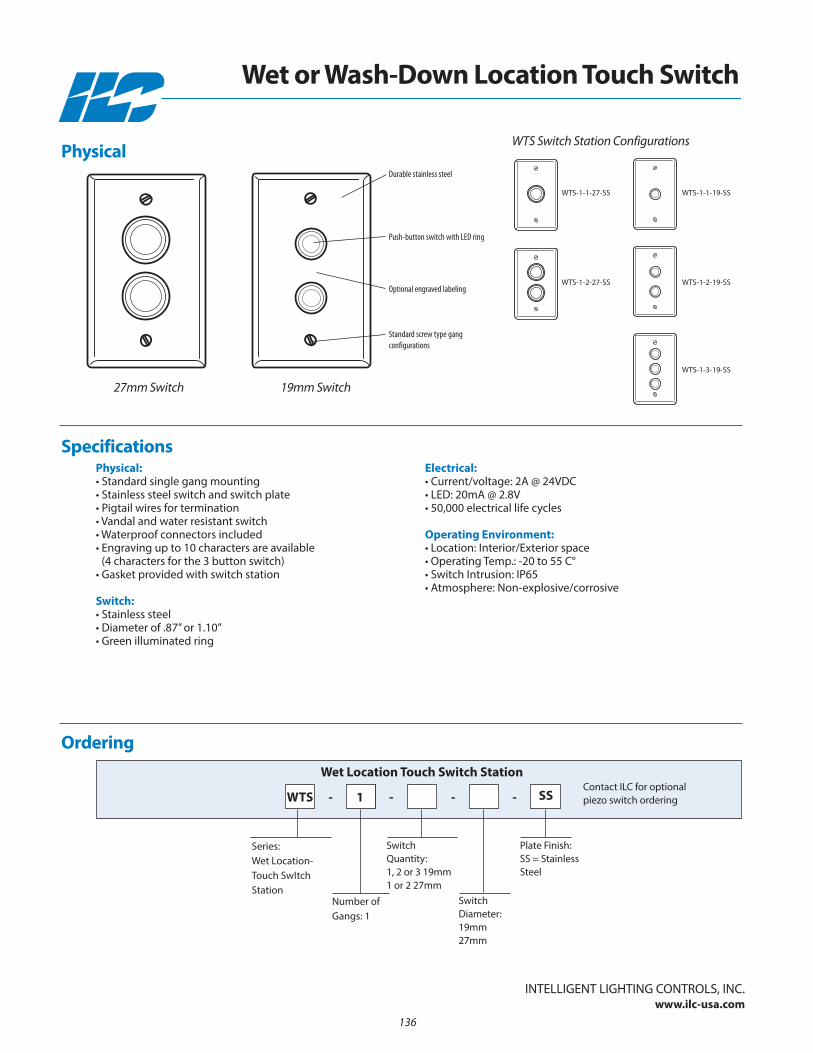
Physical:• Standard single gang mounting• Stainless steel switch and switch plate• Pigtail wires for termination• Vandal and water resistant switch• Waterproof connectors included• Engraving up to 10 characters are available
(4 characters for the 3 button switch)• Gasket provided with switch station
Switch:• Stainless steel• Diameter of .87” or 1.10”• Green illuminated ring
Electrical:• Current/voltage: 2A @ 24VDC• LED: 20mA @ 2.8V• 50,000 electrical life cycles
Operating Environment:• Location: Interior/Exterior space• Operating Temp.: -20 to 55 C° • Switch Intrusion: IP65• Atmosphere: non-explosive/corrosive
Ordering
Switch Quantity:1, 2 or 3 19mm1 or 2 27mm
number ofGangs: 1
Wet Location Touch Switch Station
Series: Wet Location-Touch SwItchStation
Specifications
InTELLIGEnT LIGHTInG COnTROLS, InC.www.ilc-usa.com
Wet or Wash-Down Location Touch Switch
-
Switch Diameter:19mm27mm
-
Plate Finish:SS = StainlessSteel
Contact ILC for optionalpiezo switch ordering-WTS 1 SS-
Physical
27mm Switch 19mm Switch
WTS Switch Station Configurations
Durable stainless steel
Push-button switch with LED ring
Optional engraved labeling
Standard screw type gang configurations
WTS-1-1-27-SS
WTS-1-2-27-SS
WTS-1-1-19-SS
WTS-1-2-19-SS
WTS-1-3-19-SS
136

• Durable vandal resistant switch station
• Made in the USA
• Life expectancy up to 50 thousand cycles
• Plate is made of l0 AWG steel
• Stainless steel push-button switch or optional piezo switch
• Program each button to control any relay, group, or preset
• Mounts in a standard single gang box
• Security screws provided
• Wire Pigtails provided for easy installation
• Painted with durable white powder paint
• Custom configurations available
FeaturesGeneral Information:
Overview The security touch switch station offers a durable push-button or optional piezo switch that is designed to control lighting control panelsor DuraTouch modules. This switch is ideal for security or severe use environment installations where an impact resistant, durable switch isrequired. This switch may be individually programmed to control any relay, group or preset throughout the network. Switch face plates aremade of 10AWG steel and painted with a durable white powder coat.
• Made in the USA
• Durable vandal resistant switch station
• 10 AWG steel plate
• Perfect for severe duty areas
• Mounts on a single gang electrical box
Security Touch SwitchTouch Activated Switch
InTELLIGEnT LIGHTInG COnTROLS, InC.www.ilc-usa.com
137
Hardwired Switch Stations

3.77”
5.52”
TORX SS security screws
.870
InTELLIGEnT LIGHTInG COnTROLS, InC.www.ilc-usa.com
138
Physical:• 10AWG steel plate• White powder coat paint• Standard single gang mounting• Stainless steel pushbutton • Pig tail wires for termination• Engraving up to 10 characters are available
Switch:• Stainless steel• Diameter of .870• nO - SPST• Status LED included
Electrical:• Current/voltage: 2A @ 24VDC
Operating Environment:• Location: Interior space• Operating Temp: -20 to 55 C• Humidity: 10% - 90% non-condensing• Atmosphere: non-explosive/corrosive• Vibration: Stationary
Ordering Touch Switch Station
Contact ILC for optional piezo switch ordering
Series: Security TouchSwItch
Specifications
Security Touch Switch
STS
Physical
Touch Activated Switch
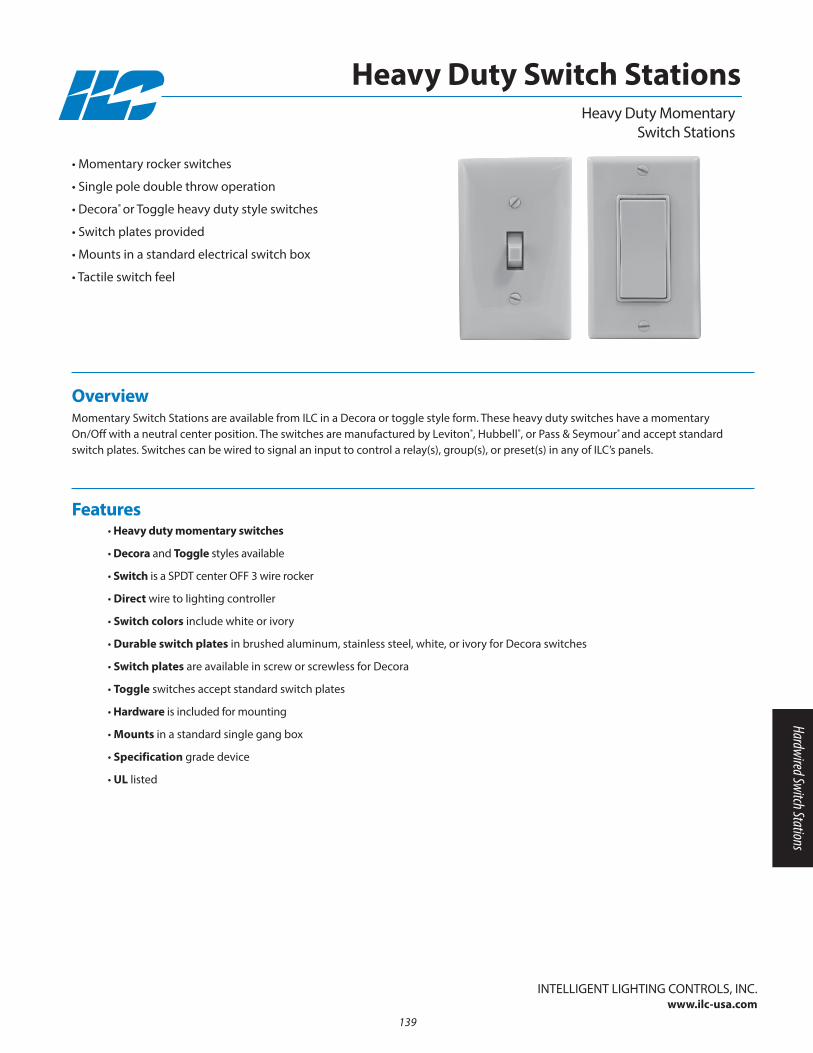
Overview Momentary Switch Stations are available from ILC in a Decora or toggle style form. These heavy duty switches have a momentaryOn/Off with a neutral center position. The switches are manufactured by Leviton®, Hubbell®, or Pass & Seymour® and accept standardswitch plates. Switches can be wired to signal an input to control a relay(s), group(s), or preset(s) in any of ILC’s panels.
• Momentary rocker switches
• Single pole double throw operation
• Decora® or Toggle heavy duty style switches
• Switch plates provided
• Mounts in a standard electrical switch box
• Tactile switch feel
• Heavy duty momentary switches
• Decora and Toggle styles available
• Switch is a SPDT center OFF 3 wire rocker
• Direct wire to lighting controller
• Switch colors include white or ivory
• Durable switch plates in brushed aluminum, stainless steel, white, or ivory for Decora switches
• Switch plates are available in screw or screwless for Decora
• Toggle switches accept standard switch plates
• Hardware is included for mounting
• Mounts in a standard single gang box
• Specification grade device
• UL listed
Features
InTELLIGEnT LIGHTInG COnTROLS, InC.www.ilc-usa.com
Heavy Duty MomentarySwitch Stations
Heavy Duty Switch Stations
139
Hardwired Switch Stations
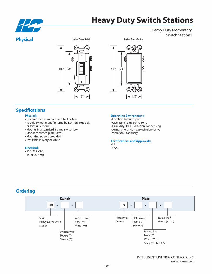
Physical:• Decora® style manufactured by Leviton• Toggle switch manufactured by Leviton, Hubbell,
or Pass & Semour• Mounts in a standard 1 gang switch box• Standard switch plate sizes• Mounting screws provided• Available in ivory or white
Electrical:• 120/277 VAC• 15 or 20 Amp
Operating Environment:• Location: Interior space• Operating Temp.: 0° to 50° C • Humidity: 10% - 90% non-condensing • Atmosphere: non-explosive/corrosive • Vibration: Stationary
Certifications and Approvals:• UL• CSA
Physical
Specifications
Ordering
Plate color: Ivory (IV) White (WH), Stainless Steel (SS)
HD - - - -
Switch Plate
Plate cover: Plain (P) Screws (S)
-
Plate style: Decora
number of Gangs (1 to 4)
Heavy Duty MomentarySwitch Stations
Heavy Duty Switch Stations
Leviton Toggle Switch
InTELLIGEnT LIGHTInG COnTROLS, InC.www.ilc-usa.com
1.37”
4.06” 3.28”
Leviton Decora Switch
1.30”
4.06” 3.28”
Switch color: Ivory (IV) White (WH)
Series:Heavy Duty SwitchStation
Switch style: Toggle (T) Decora (D)
D
140

• Switches are heavy duty momentary or maintained
• Made in the USA
• Secure 5-tumbler high quality switches
• Direct wire to lighting controller
• Switch stations handle up to 8 switches on a 4 gang plate
• Status LEDs are optional for each switch
• Durable switch plates in brushed aluminum, stainless steel, white, or custom configurations
• Hardware is included for mounting and wiring
• Mounts in a standard switch box
• Wires are installed for easy termination
• Optional engraving for switch identification
• Custom configurations available
• Program each button to control any relay(s), group(s) or preset(s)
Features
Overview Key switch stations provide an extra level of security that limits lighting control access to only those with the appropriate key. Switchstations have a high quality 5 tumbler key switch and an optional status LED. Key switches are prewired and ready to install in anystandard switch box. Switch plates are available in brushed aluminum, stainless steel, white, or created to your custom requirements.
• Secure switching and control
• Made in the USA
• Momentary or maintained switches
• 1 to 8 switch configurations
• Status LEDs available for each switch
• Mounts in a standard electrical switch box
• Engraved switch identification available
• Custom configurations available
InTELLIGEnT LIGHTInG COnTROLS, InC.www.ilc-usa.com
Key Switch StationsStandard Low Voltage
Switches & Plates
141
Hardwired Switch Stations
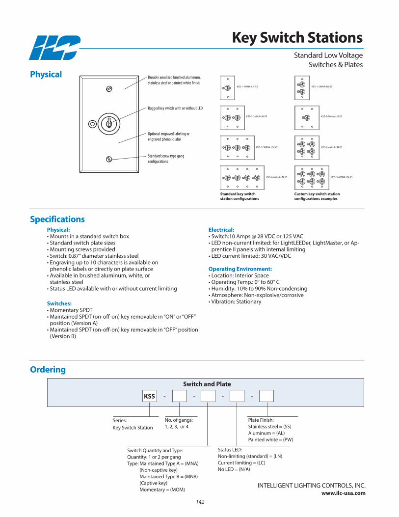
Physical:• Mounts in a standard switch box• Standard switch plate sizes• Mounting screws provided• Switch: 0.87” diameter stainless steel• Engraving up to 10 characters is available on
phenolic labels or directly on plate surface• Available in brushed aluminum, white, or
stainless steel• Status LED available with or without current limiting
Switches:• Momentary SPDT • Maintained SPDT (on-off-on) key removable in “On” or “OFF”
position (Version A)• Maintained SPDT (on-off-on) key removable in “OFF” position
(Version B)
Electrical:• Switch:10 Amps @ 28 VDC or 125 VAC• LED non-current limited: for LightLEEDer, LightMaster, or Ap-
prentice II panels with internal limiting• LED current limited: 30 VAC/VDC
Operating Environment:• Location: Interior Space• Operating Temp.: 0° to 60° C • Humidity: 10% to 90% non-condensing • Atmosphere: non-explosive/corrosive• Vibration: Stationary
Ordering
no. of gangs:1, 2, 3, or 4
Series: Key Switch Station
Switch and Plate
Status LED:non-limiting (standard) = (Ln)Current limiting = (LC)no LED = (n/A)
Plate Finish:Stainless steel = (SS)Aluminum = (AL)Painted white = (PW)
Switch Quantity and Type:Quantity: 1 or 2 per gangType: Maintained Type A = (MnA)
(non-captive key)Maintained Type B = (MnB)(Captive key)Momentary = (MOM)
Physical
Specifications
InTELLIGEnT LIGHTInG COnTROLS, InC.www.ilc-usa.com
Key Switch Stations
KSS - - - -
Standard Low VoltageSwitches & Plates
KSS-1-1MnA-Ln-SS
KSS-1-2MnA-Ln-SS
KSS-3-3MnA-Ln-SS
KSS-4-4MnA-Ln-SS
KSS-1-2MnA-Ln-SS
KSS-2-1MnA-Ln-SS
KSS-2-4MnA-Ln-SS
KSS-3-6MnA-Ln-SS
Custom key switch station configurations examples
Standard key switch station configurations
Durable anodized brushed aluminum,stainless steel or painted white finish
Rugged key switch with or without LED
Optional engraved labeling or engraved phenolic label
Standard screw type gang configurations
142
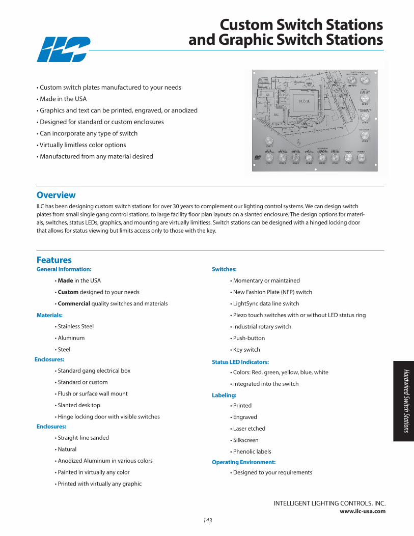
• Made in the USA
• Custom designed to your needs
• Commercial quality switches and materials
FeaturesGeneral Information:
• Stainless Steel
• Aluminum
• Steel
Materials:
• Standard gang electrical box
• Standard or custom
• Flush or surface wall mount
• Slanted desk top
• Hinge locking door with visible switches
Enclosures:
• Straight-line sanded
• natural
• Anodized Aluminum in various colors
• Painted in virtually any color
• Printed with virtually any graphic
Enclosures:
Overview ILC has been designing custom switch stations for over 30 years to complement our lighting control systems. We can design switchplates from small single gang control stations, to large facility floor plan layouts on a slanted enclosure. The design options for materi-als, switches, status LEDs, graphics, and mounting are virtually limitless. Switch stations can be designed with a hinged locking doorthat allows for status viewing but limits access only to those with the key.
• Custom switch plates manufactured to your needs
• Made in the USA
• Graphics and text can be printed, engraved, or anodized
• Designed for standard or custom enclosures
• Can incorporate any type of switch
• Virtually limitless color options
• Manufactured from any material desired
• Momentary or maintained
• new Fashion Plate (nFP) switch
• LightSync data line switch
• Piezo touch switches with or without LED status ring
• Industrial rotary switch
• Push-button
• Key switch
Switches:
• Colors: Red, green, yellow, blue, white
• Integrated into the switch
Status LED Indicators:
• Printed
• Engraved
• Laser etched
• Silkscreen
• Phenolic labels
Labeling:
• Designed to your requirements
Operating Environment:
InTELLIGEnT LIGHTInG COnTROLS, InC.www.ilc-usa.com
Custom Switch Stations and Graphic Switch Stations
143
Hardwired Switch Stations
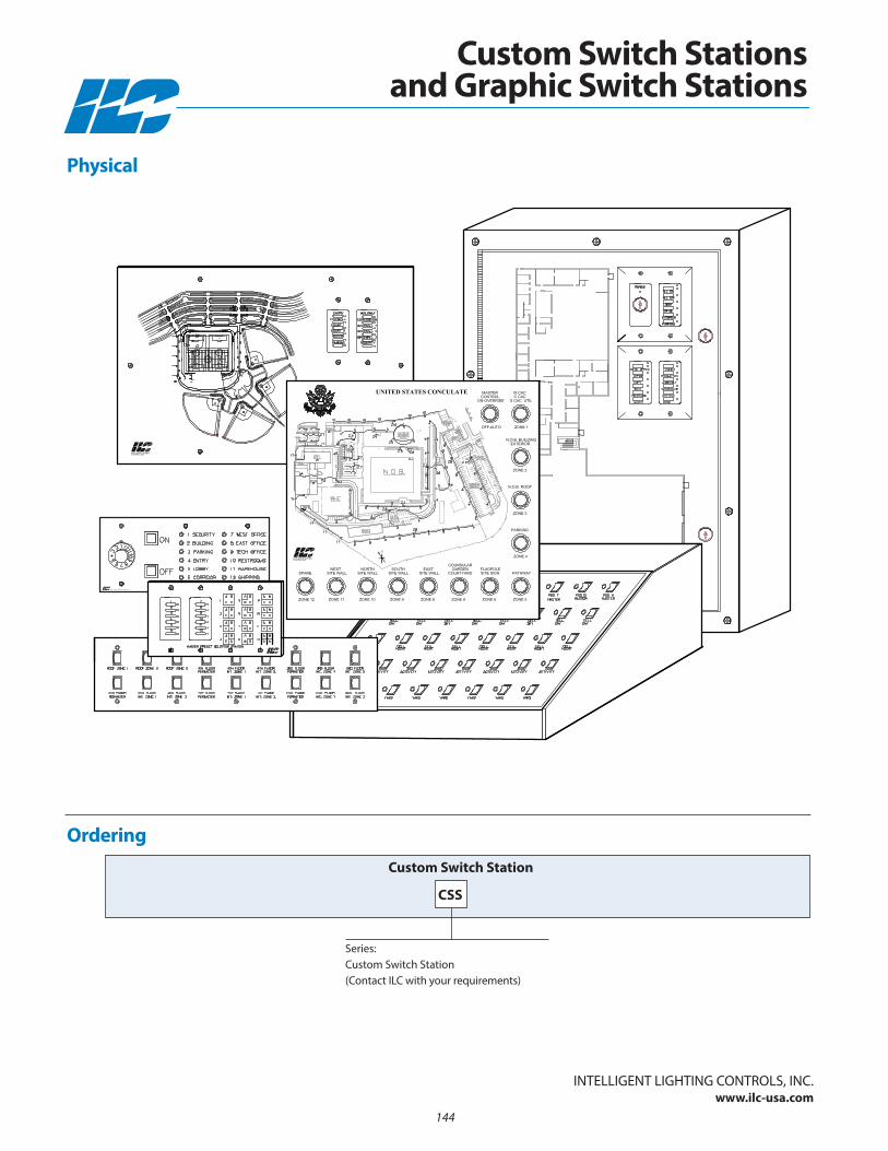
Ordering
Series: Custom Switch Station (Contact ILC with your requirements)
Custom Switch Station
Physical
InTELLIGEnT LIGHTInG COnTROLS, InC.www.ilc-usa.com
Custom Switch Stations and Graphic Switch Stations
CSS
144
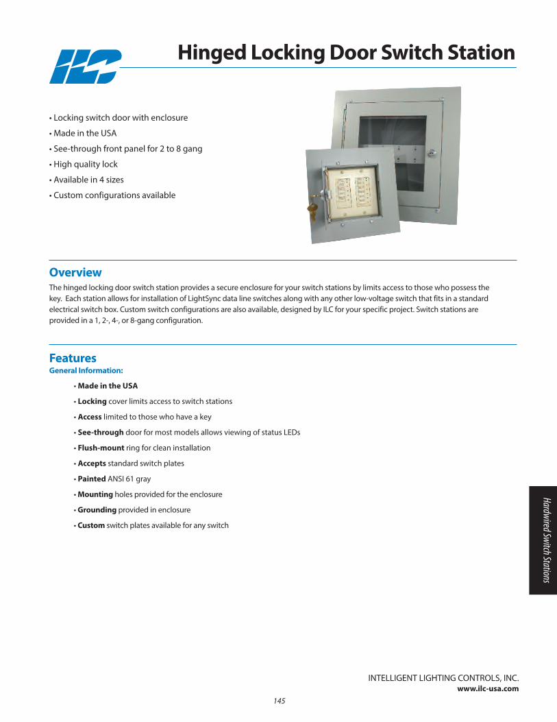
• Made in the USA
• Locking cover limits access to switch stations
• Access limited to those who have a key
• See-through door for most models allows viewing of status LEDs
• Flush-mount ring for clean installation
• Accepts standard switch plates
• Painted AnSI 61 gray
• Mounting holes provided for the enclosure
• Grounding provided in enclosure
• Custom switch plates available for any switch
FeaturesGeneral Information:
Overview The hinged locking door switch station provides a secure enclosure for your switch stations by limits access to those who possess thekey. Each station allows for installation of LightSync data line switches along with any other low-voltage switch that fits in a standardelectrical switch box. Custom switch configurations are also available, designed by ILC for your specific project. Switch stations are provided in a 1, 2-, 4-, or 8-gang configuration.
• Locking switch door with enclosure
• Made in the USA
• See-through front panel for 2 to 8 gang
• High quality lock
• Available in 4 sizes
• Custom configurations available
InTELLIGEnT LIGHTInG COnTROLS, InC.www.ilc-usa.com
Hinged Locking Door Switch Station
145
Hardwired Switch Stations
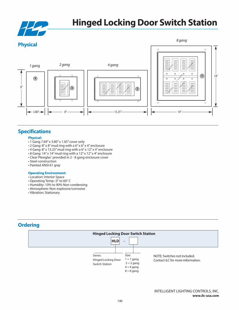
Physical:• 1 Gang 7.69” x 3.80” x 1.05” cover only• 2 Gang: 8” x 8” mud ring with a 6” x 6” x 4” enclosure• 4 Gang: 8” x 13.25” mud ring with a 6” x 12” x 4” enclosure• 8 Gang: 14” x 14” mud ring with a 12” x 12” x 4” enclosure• Clear Plexiglas® provided in 2 - 8 gang enclosure cover• Steel construction• Painted AnSI 61 gray
Operating Environment:• Location: Interior Space• Operating Temp.: 0° to 60° C • Humidity: 10% to 90% non-condensing • Atmosphere: non-explosive/corrosive• Vibration: Stationary
Ordering
Size:1 = 1 gang2 = 2 gang4 = 4 gang8 = 8 gang
Series: Hinged Locking DoorSwitch Station
Hinged Locking Door Switch Station
Specifications
InTELLIGEnT LIGHTInG COnTROLS, InC.www.ilc-usa.com
Hinged Locking Door Switch Station
HLD -
Physical
nOTE: Switches not included. Contact ILC for more information.
2 gang 1 gang 4 gang
8 gang
8”
8”3.80”
14”
13.25” 14”
146

Section 12: Specialty and Obsolete Products
• Current Limiting Subpanel
• DuraTouch
• 2R Relays
• TR Relays
• TR Relay Accessories
147
Specialty and Obsolete Parts

148
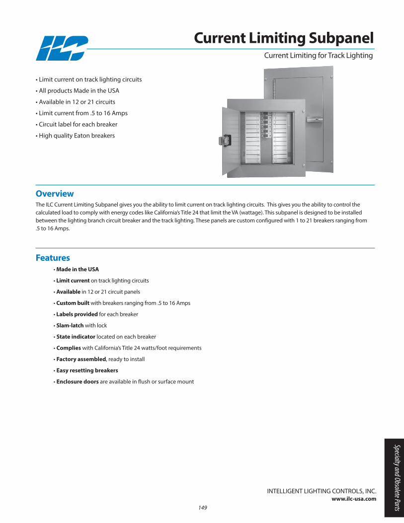
Overview The ILC Current Limiting Subpanel gives you the ability to limit current on track lighting circuits. This gives you the ability to control the calculated load to comply with energy codes like California’s Title 24 that limit the VA (wattage). This subpanel is designed to be installed between the lighting branch circuit breaker and the track lighting. These panels are custom configured with 1 to 21 breakers ranging from .5 to 16 Amps.
• Limit current on track lighting circuits
• All products Made in the USA
• Available in 12 or 21 circuits
• Limit current from .5 to 16 Amps
• Circuit label for each breaker
• High quality Eaton breakers
Current Limiting for Track Lighting
• Made in the USA
• Limit current on track lighting circuits
• Available in 12 or 21 circuit panels
• Custom built with breakers ranging from .5 to 16 Amps
• Labels provided for each breaker
• Slam-latch with lock
• State indicator located on each breaker
• Complies with California’s Title 24 watts/foot requirements
• Factory assembled, ready to install
• Easy resetting breakers
• Enclosure doors are available in flush or surface mount
Features
InTELLIGEnT LIGHTInG COnTROLS, InC.www.ilc-usa.com
Current Limiting Subpanel
149
Specialty and Obsolete Parts
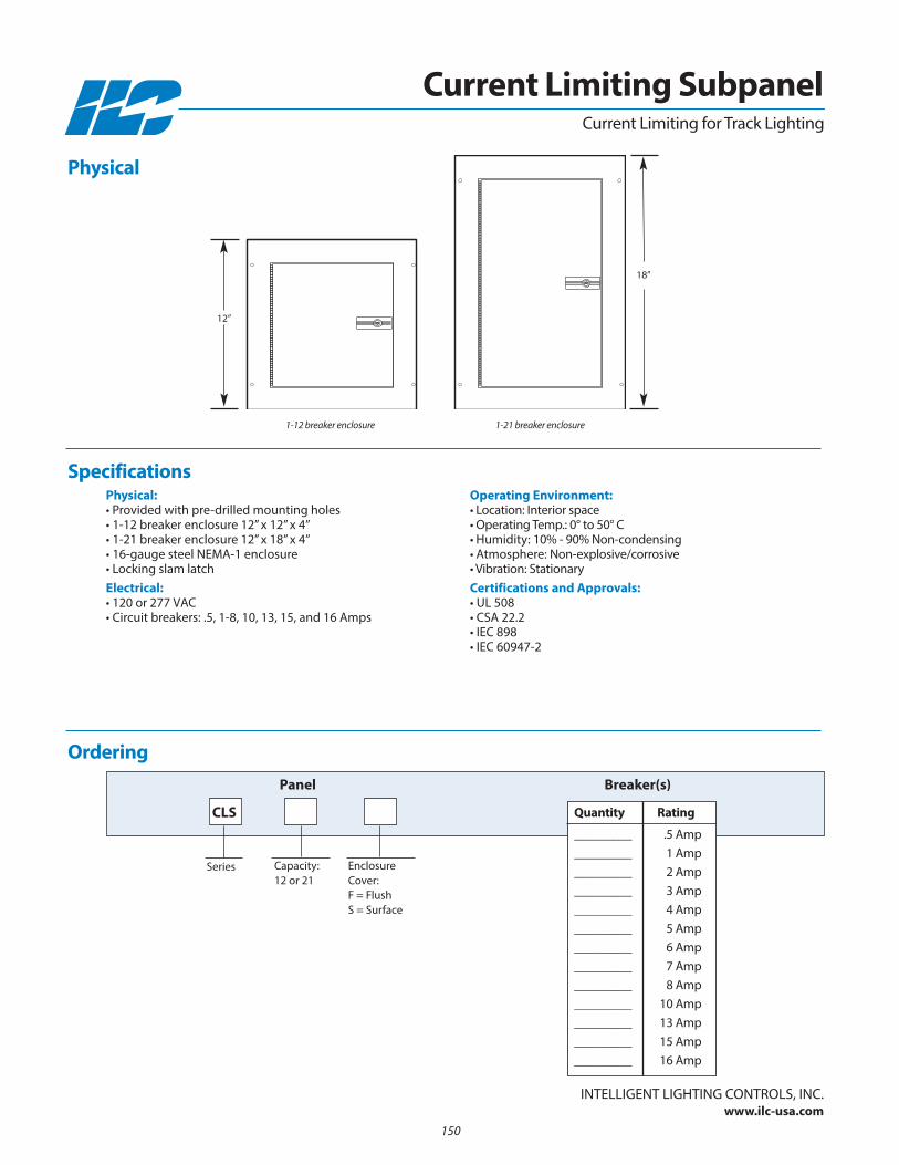
150
Physical:• Provided with pre-drilled mounting holes• 1-12 breaker enclosure 12” x 12” x 4”• 1-21 breaker enclosure 12” x 18” x 4”• 16-gauge steel nEMA-1 enclosure• Locking slam latchElectrical:• 120 or 277 VAC• Circuit breakers: .5, 1-8, 10, 13, 15, and 16 Amps
Operating Environment:• Location: Interior space• Operating Temp.: 0° to 50° C • Humidity: 10% - 90% non-condensing • Atmosphere: non-explosive/corrosive • Vibration: StationaryCertifications and Approvals:• UL 508• CSA 22.2• IEC 898• IEC 60947-2
Ordering
Current Limiting for Track Lighting
Capacity: 12 or 21
Series
CLS
Panel
EnclosureCover: F = FlushS = Surface
Breaker(s)
Physical
Specifications
InTELLIGEnT LIGHTInG COnTROLS, InC.www.ilc-usa.com
Current Limiting Subpanel
1-12 breaker enclosure 1-21 breaker enclosure
18”
12”
Quantity Rating
_________ .5 Amp_________ 1 Amp_________ 2 Amp_________ 3 Amp_________ 4 Amp_________ 5 Amp_________ 6 Amp_________ 7 Amp_________ 8 Amp_________ 10 Amp_________ 13 Amp_________ 15 Amp_________ 16 Amp

• Made in the USA
• Self contained lighting controller
• Packaged in a junction or fixture mount
• Programmable switch sequence control
• Power-up setting sets load to desired state upon power-up
• Solid state zero-cross outputs
• Controls up to 3-120 or 277VAC loads
• Inputs can handle momentary or maintained closures
• Status output provided for each output
• Memory stores programming up to 10 years without power
• Programmed at the factory or in the field
• Touch-switch available for security and harsh areas
• Security plates available for prison applications
FeaturesGeneral Information:
Overview The DuraTouch provides a flexible and cost-effective lighting controller that is ideal for hospitals, prisons, and single room applications.Each unit can be custom programmed to your needs. This module provides 3 switch inputs, 1 timed-on input, 2 override inputs, 3 zero-cross outputs, and low voltage status outputs for each load. Each output is designed to control 120 or 277VAC loads up to 200 watts per output with 1 load isolated. Modules are available in a 4-11/16” junction box mount and a chase mount designed for fluorescent fixtures. With the addition of a piezo solid state switch, this unit is ideal for harsh areas, and for protecting against vandalism..
• Self-contained programmable lighting controller
• Made in the USA
• Programmable switching sequence
• Solid state zero cross switching
• Controls up to 3-120 or 277VAC loads
• Vandal resistant touch switch and security
plates available
InTELLIGEnT LIGHTInG COnTROLS, InC.www.ilc-usa.com
Self-Contained Programmable Lighting Controller
151
Specialty and Obsolete Parts

Physical:• Junction box mount: 4.76” x 4.76” x 1.50”• Fixture mount: 9.50” x 2.50” x 1.50”• .250 push-on high voltage connections• .187 push-on low voltage connections• RJ11 programming jack• Clearly marked connections
Electrical:• 120 or 277VAC• 1 to 3 outputs• 200 watts per channel • Maximum Inrush: 4 amps for 1 cycle, 2 minutes
between cycle
Operating Environment:• Location: Interior Space• Operating Temp.: 0° to 50° C • Humidity: 10% to 90% non-condensing • Atmosphere: non-explosive/corrosive• Vibration: Stationary
Certifications and Approvals:• UL
See Switch Stations for security platesand switches.
Ordering
Mount:JB= Junction BoxFM = Fixture
Series: Dura Touch Programmable Lighting Controller
Dura Touch Controller
Specifications
InTELLIGEnT LIGHTInG COnTROLS, InC.www.ilc-usa.com
DT -
Physical
LOAD
1
N 120LO
AD 2
LOAD
3
LED COM.
LED 1
LED 2
LED 3
INPU
T CO
M.
INPU
T 1
INPU
T 2
INPU
T 3
OR 1
OR 2
TIM
ED O
N
LINE
3
LINE
2N 277LINE
LOAD 3 INTELLIGENT LIGHTING CONTROLS, INC.
LOAD 3 POWER
LOAD 1,2 POWER
LOAD 2
LOAD 1
LOAD 1,2 POWER
277 NEUT
120 NEUT
INPUT 1
RJ-11
INPUT 2
INPUT 3
INPUT 4
INPUT 5
INPUT 6
SWITCH COMMON
STATUS COMMON
STATUS 1
STATUS 2
STATUS 3
MODEL: DURATOUCH-FM P/N REV.
OUTPUT — MAXIMUM 3 LOADS (TUNGSTEN / BALLAST) 120 / 277 VAC, 60Hz, 200 W each
RATINGS: INPUT POWER - 120/277 VAC 60 Hz, 600 W
Junction BoxMount
Fixture Mount
2.5”
9.5”
4.76”
4.76”
Self-Contained Programmable Lighting Controller
152
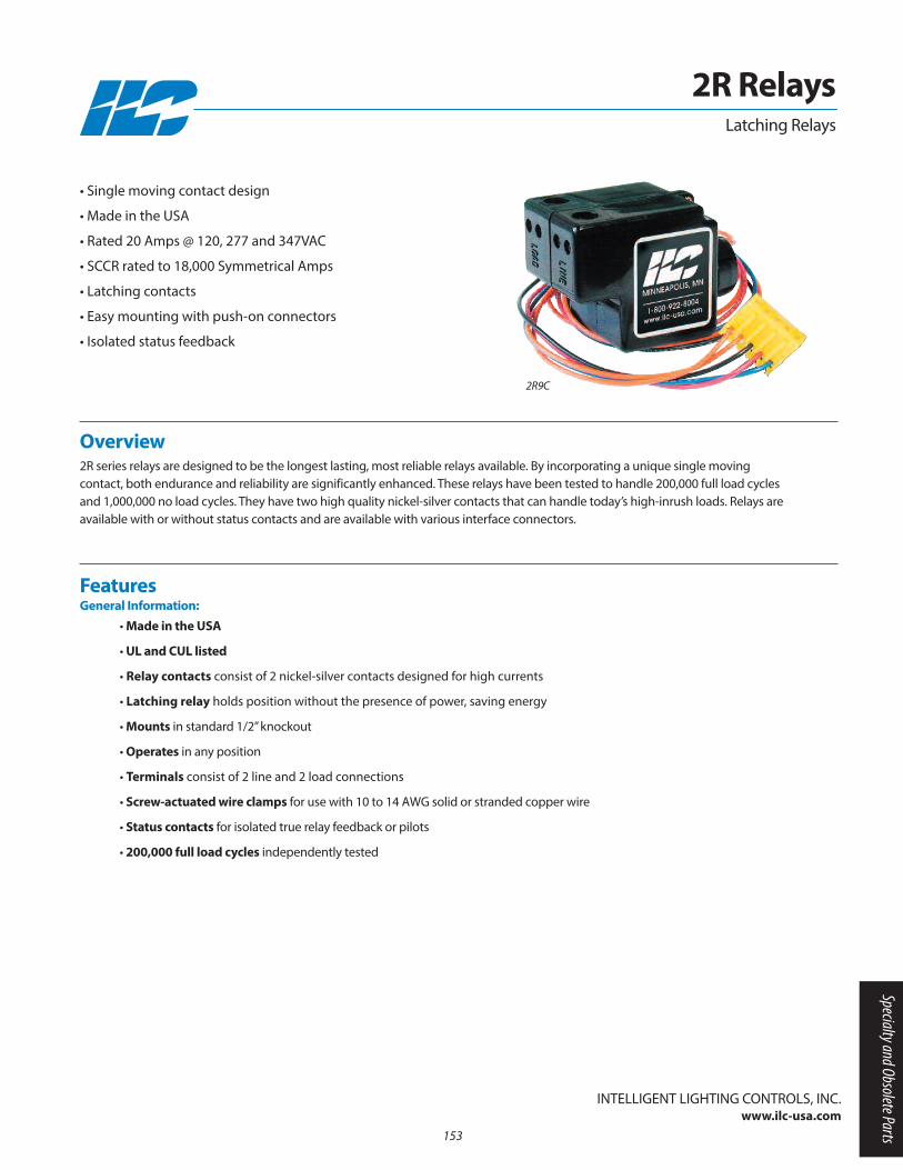
• Made in the USA
• UL and CUL listed
• Relay contacts consist of 2 nickel-silver contacts designed for high currents
• Latching relay holds position without the presence of power, saving energy
• Mounts in standard 1/2” knockout
• Operates in any position
• Terminals consist of 2 line and 2 load connections
• Screw-actuated wire clamps for use with 10 to 14 AWG solid or stranded copper wire
• Status contacts for isolated true relay feedback or pilots
• 200,000 full load cycles independently tested
FeaturesGeneral Information:
Overview 2R series relays are designed to be the longest lasting, most reliable relays available. By incorporating a unique single moving contact, both endurance and reliability are significantly enhanced. These relays have been tested to handle 200,000 full load cyclesand 1,000,000 no load cycles. They have two high quality nickel-silver contacts that can handle today’s high-inrush loads. Relays are available with or without status contacts and are available with various interface connectors.
• Single moving contact design
• Made in the USA
• Rated 20 Amps @ 120, 277 and 347VAC
• SCCR rated to 18,000 Symmetrical Amps
• Latching contacts
• Easy mounting with push-on connectors
• Isolated status feedback
InTELLIGEnT LIGHTInG COnTROLS, InC.www.ilc-usa.com
2R RelaysLatching Relays
2R9C
153
Specialty and Obsolete Parts
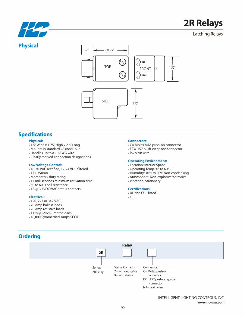
Physical:• 1.5” Wide x 1.75” High x 2.6” Long• Mounts in standard 1⁄2” knock-out• Handles up to a 10 AWG wire• Clearly marked connection designations
Low Voltage Control:• 18-30 VAC rectified, 12-24 VDC filtered• 175-350mA• Momentary duty rating• 17 milliseconds minimum activation time • 50 to 60 Ω coil resistance• 1A @ 30 VDC/VAC status contacts
Electrical:• 120, 277 or 347 VAC• 20 Amp ballast loads• 20 Amp resistive loads• 1 Hp @120VAC motor loads• 18,000 Symmetrical Amps SCCR
Connectors:• C= Molex MTA push-on connector• EZ= .157 push-on spade connector • P= plain wire
Operating Environment:• Location: Interior Space• Operating Temp.: 0° to 60° C • Humidity: 10% to 90% non-condensing • Atmosphere: non-explosive/corrosive• Vibration: Stationary
Certifications:• UL and CUL listed• FCC
Ordering
Status Contacts:7= without status9= with status
Series: 2R Relay
Relay
Connector:C= Molex push-on
connectorEZ= .157 push-on spade
connectornA= plain wire
Specifications
InTELLIGEnT LIGHTInG COnTROLS, InC.www.ilc-usa.com
2R Relays
2.0625”.52”
1.75”
1.50”TOP
2R
Physical
Latching Relays
FROnT
SIDE
154
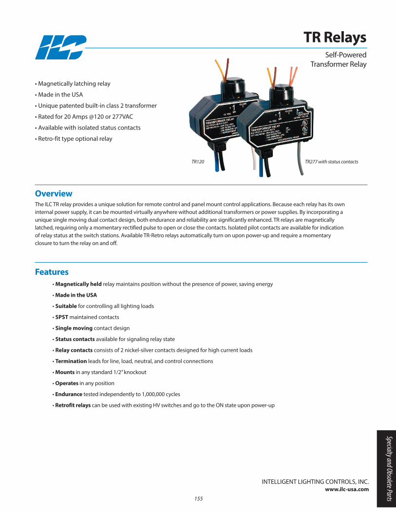
• Magnetically held relay maintains position without the presence of power, saving energy
• Made in the USA
• Suitable for controlling all lighting loads
• SPST maintained contacts
• Single moving contact design
• Status contacts available for signaling relay state
• Relay contacts consists of 2 nickel-silver contacts designed for high current loads
• Termination leads for line, load, neutral, and control connections
• Mounts in any standard 1/2” knockout
• Operates in any position
• Endurance tested independently to 1,000,000 cycles
• Retrofit relays can be used with existing HV switches and go to the On state upon power-up
Features
Overview The ILC TR relay provides a unique solution for remote control and panel mount control applications. Because each relay has its owninternal power supply, it can be mounted virtually anywhere without additional transformers or power supplies. By incorporating aunique single moving dual contact design, both endurance and reliability are significantly enhanced. TR relays are magneticallylatched, requiring only a momentary rectified pulse to open or close the contacts. Isolated pilot contacts are available for indicationof relay status at the switch stations. Available TR-Retro relays automatically turn on upon power-up and require a momentary closure to turn the relay on and off.
• Magnetically latching relay
• Made in the USA
• Unique patented built-in class 2 transformer
• Rated for 20 Amps @120 or 277VAC
• Available with isolated status contacts
• Retro-fit type optional relay
InTELLIGEnT LIGHTInG COnTROLS, InC.www.ilc-usa.com
TR RelaysSelf-Powered
Transformer Relay
TR120 TR277 with status contacts
155
Specialty and Obsolete Parts
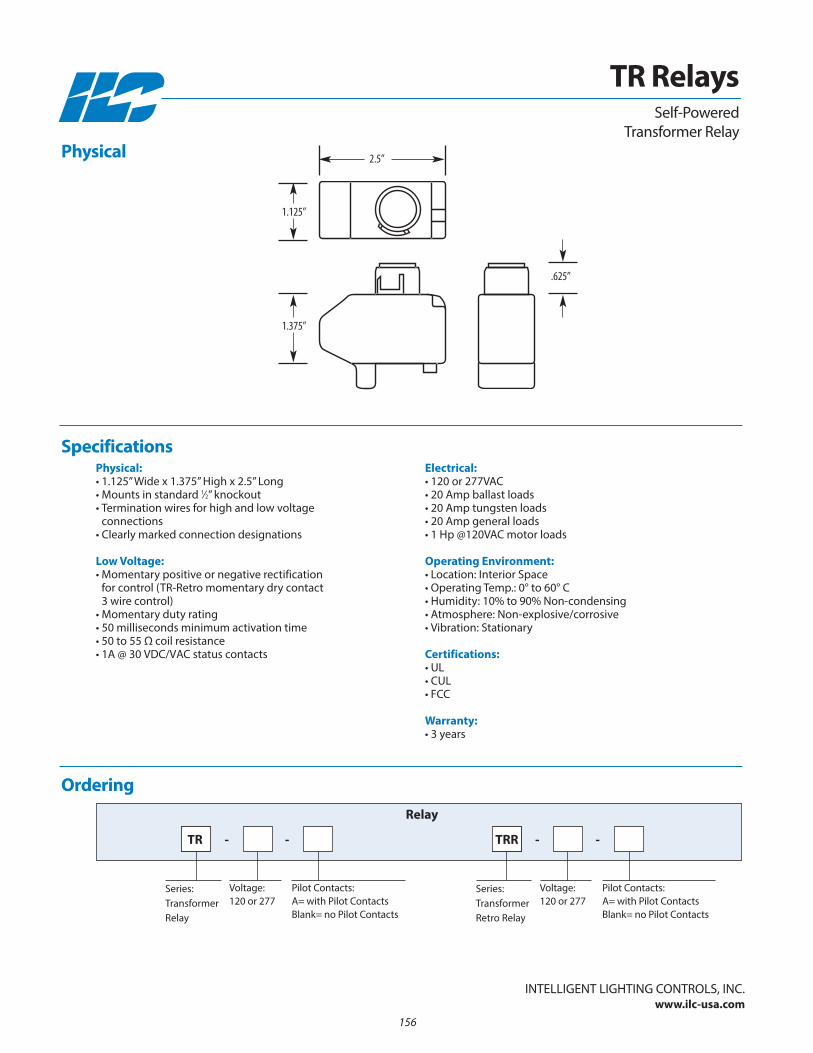
Physical:• 1.125” Wide x 1.375” High x 2.5” Long• Mounts in standard 1⁄2” knockout• Termination wires for high and low voltage
connections• Clearly marked connection designations
Low Voltage:• Momentary positive or negative rectification
for control (TR-Retro momentary dry contact 3 wire control)
• Momentary duty rating• 50 milliseconds minimum activation time • 50 to 55 Ω coil resistance• 1A @ 30 VDC/VAC status contacts
Electrical:• 120 or 277VAC• 20 Amp ballast loads• 20 Amp tungsten loads• 20 Amp general loads• 1 Hp @120VAC motor loads
Operating Environment:• Location: Interior Space• Operating Temp.: 0° to 60° C • Humidity: 10% to 90% non-condensing • Atmosphere: non-explosive/corrosive• Vibration: Stationary
Certifications:• UL• CUL• FCC
Warranty:• 3 years
Ordering
Voltage:120 or 277
Series: TransformerRelay
Relay
Pilot Contacts:A= with Pilot ContactsBlank= no Pilot Contacts
Specifications
InTELLIGEnT LIGHTInG COnTROLS, InC.www.ilc-usa.com
TR Relays
TR - -
Voltage:120 or 277
Series: TransformerRetro Relay
Pilot Contacts:A= with Pilot ContactsBlank= no Pilot Contacts
TRR - -
Physical
Self-Powered Transformer Relay
1.125”
2.5”
1.375”
.625”
156
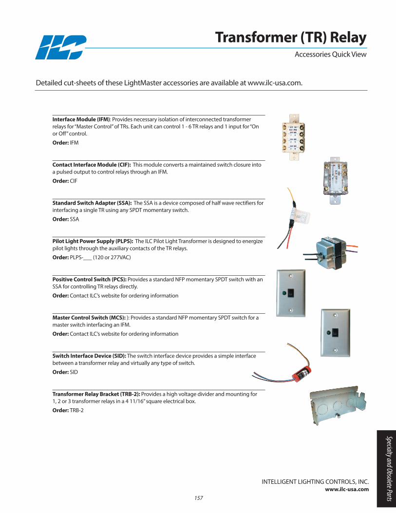
Interface Module (IFM): Provides necessary isolation of interconnected transformer relays for “Master Control” of TRs. Each unit can control 1 - 6 TR relays and 1 input for “On or Off” control.
Order: IFM
Contact Interface Module (CIF): This module converts a maintained switch closure intoa pulsed output to control relays through an IFM.
Order: CIF
Standard Switch Adapter (SSA): The SSA is a device composed of half wave rectifiers forinterfacing a single TR using any SPDT momentary switch.
Order: SSA
Pilot Light Power Supply (PLPS): The ILC Pilot Light Transformer is designed to energizepilot lights through the auxiliary contacts of the TR relays.
Order: PLPS-___ (120 or 277VAC)
Positive Control Switch (PCS): Provides a standard nFP momentary SPDT switch with anSSA for controlling TR relays directly.
Order: Contact ILC’s website for ordering information
Master Control Switch (MCS): ): Provides a standard nFP momentary SPDT switch for amaster switch interfacing an IFM.
Order: Contact ILC’s website for ordering information
Switch Interface Device (SID): The switch interface device provides a simple interfacebetween a transformer relay and virtually any type of switch.
Order: SID
Transformer Relay Bracket (TRB-2): Provides a high voltage divider and mounting for 1, 2 or 3 transformer relays in a 4 11/16” square electrical box.
Order: TRB-2
Detailed cut-sheets of these LightMaster accessories are available at www.ilc-usa.com.
InTELLIGEnT LIGHTInG COnTROLS, InC.www.ilc-usa.com
Accessories Quick View
Transformer (TR) Relay
157
Specialty and Obsolete Parts

158

nOTES
159

160
Recommended