Work Performed Under Contract No. A101-78CS54209
August 31, 1984
LIBRARY COpy
LANGLEY RESEARCH GENTI;RLIBRARY, NASA
H;"r'"~ToN, VIRGIt-\IA
ByH. W. Schneider
DOE/CS/54209-15(DE85004585)
EVALUATION OF HEAT ENGINES FOR HYBRID VEHICLEAPPLICATION
NASA-CR-174163 B~E!,"S
'OS I~ 3JifU . . ,\~g'5 a00 qerS'!
Jet Propulsion LaboratoryPasadena, California
Technical Information Center
Office of Scientific and Technical Information
United States Department of Energy
https://ntrs.nasa.gov/search.jsp?R=19850004937 2018-07-08T13:26:32+00:00Z
DISCLAIMER
This report was prepared as an account of work sponsored by an agency of the United StatesGovernment. Neither the United States Government nor any agency thereof, nor any of theiremployees, makes any warranty, ex.press or implied, or assumes any legal liability or responsi·bility for the accuracy, completeness, or usefulness of any information, apparatus, product, orprocess disclosed, or represents that its use would not infringe privately owned rights. Reference herein to any specific commercial product, process, or service by trade name, trademark,manufacturer, or otherwise does not necessarily constitute or imply its endorsement, recommendation, or favoring by the United States Government or any agency thereof. The viewsand opinions of authors expressed herein do not necessarily state or reflect those of theUnited States Government or any agency thereof.
This report has been reproduced directly from the best available copy.
Available from the National Technical Information Service, U. S. Department of Commerce,Springfield, Virginia 22161.
Price: Printed Copy A04Microfiche AO I
Codes are used for pricing all pubhcations. The code is determined by the number of pages in thepublication. Information pertaining to the pricing codes can be found in the current issues of thefollowing publications, which are generally available in most libraries: Energy Research Abstracts(ERA); Government Reports Announcements and Index (GRA and I); Scientific and TechnicalAbstract Reports (STAR); and publication NTIS-PR-360 available from NTIS at the aboveaddress.
SELECT UTP/EVALUATION *+2 HEATNO HITS SELECTING TERM -OR INVALID REFERENCE NUMBER
================================================================================C:!="l !="CT._':..-:..-:.-.~: UTP;EVALUATION *+2 HEAT
================================================================================
37 RPT*~ fiASA-CR-17416~DOE/CS-5420~jl~o CNT;:
NAS7-918 DE-AI01-78CS-54209 84/08/31 72 PAGES UNCLASSIFIED DOCUMlNTUTTL: Evaluation of heat engjne for hYbrid vehicle apPli·cationAUTH: A/SCHNEIDER, H: W~
CORP: Jet.Propulsion Lab:~ California Inst: of Tech:, Pasade~a:
SAP:HC A04/MF AOI
EXHAtJ:3T FUEL
AB:3; Ti1E: statt~E~ ()f ()f19() i r"%9 f·!eat,-erf~.i ne cie\!e I oPfner!ts~ inc1\Jci i n9 spar~.. - i 9rl it i ()fl,
compression-ignition! internal-combustion, and external-combustion en91nesis preserlte(~~ Trle pc-terlt,ial ()f err~irle c:()r~cept~3 t~n(ier c:or!~3i(lerati()r) f~)r
hYbri-d -veh1cle use is evaluated, using self-imposed criteria forselection: The deficiencies of the engines curre~tly being evaluated inhybrlQ vehicles are-discussed: Focus 18 on recent research withtwo-stroKe~ rotary, and free-piston eu91nes= It is concluded tha th~seengine concepts have the most promising potentj-ai for future 3PP lcationin hYbrid vehlcles~ Recommendations are made for analysis and
-Ef~TER:

.•
5030-568Electric & Hybrid Vehicle SystemResearch & Development Project
DOE/CS/54209·15(DE85004585)
Distribution Category UC·96
Evaluation of Heat Engines forHybrid Vehicle Application
H.W. SChneider
August 31, 1984
Prepared for
U.S. Department of Energy
Through an Agreement withNational Aeronautics and Space Administration
by
Jet Propulsion LaboratoryCalifornia Institute of TechnologyPasadena, California
JPL Publication 84-14

ABSTRACT
The status of ongoing heat-engine developments, including spark-ignition,compression-ignition, internal-combustion, and e<ternal-combustion engines ispresented in this report. The potential of engine concepts under consideration for hybrid vehicle use is evaluated, using self-imposed criteria forselection. The deficiencies of the engines currently being evaluated inhybrid vehicles are discussed. The study focuses on recent research withtwo-stroke, rotary, and free-piston engines and concludes that these engineconcepts have the most promising potential for future application in hybridvehicles. Recommendations are made for analysis and experimentation toevaluate stop-start and transient emission behavior of recommended engineconcepts.
ACKNOWLEDGMENTS
The author wishes to express appreciation to Barbara Bonzo andThedra McMillian, members of the EHV team, and Catherine Edwards, editor,for their valuable contributions to this report.
iii

PART ONE:
A.
CONTENTS
EXECUTIVE SUMMARY
INTRODUCTION AND SCOPE 1
B.
C.
CONCLUSIONS • • •
RECOMMENDATIONS •
• 3
8
D. SUMMARY OF CURRENT HEAT-ENGINE RESEARCHAND DEVELOPMENT • • • • • • • • • • • • . . . . . . . . 8
PART TWO:
I.
EVALUATION OF HEAT ENGINES
METHODOLOGY FOR HYBRID HEAT-ENGINE EVALUATION . . . 1-1
A.
B.
C.
PRIMARY ELECTRIC CAR WITH AUXILIARY HEAT ENGINE
PRIMARY HEAT-ENGINE-DRIVEN CAR WITH AUXILIARYELECTRIC POWERTRAIN ••• • • • • • •
HEAT-ENGINE RECHARGEABLE PRIMARY ELECTRIC CAR
• •
1-1
1-1
1-1
D. TRUE HYBRID HEAT-ENGINE/ELECTRIC CAR . . 1-2
I I. STATUS REVIEW OF VARIOUS HEAT-ENGINE CONCEPTS 2-1
A. SPARK-IGNITION ENGINES . . . . 2-1
1.
2.
3.
Four-Stroke Piston Engines
Four-Stroke Rotary Engines
Two-Stroke Piston Engines •
2-1
2-3
2-4
B. COMPRESSION-IGNITION ENGINES (DIESEL) 2-15
L
2.
Indirect-Injection Diesel Engines
Direct-Injection Diesel Engines
2-15
2-18
C. EXTERNAL COMBUSTION ENGINES • • • •
Brayton Engines (Gas Turbine)
2-18
2-18
2.
3.
Stirling Engines •••••••
Rankine Engines (Steam Engine)
v
•
•
2-20
2-22
D. FUEL-INJECTION SYSTEMS • • • • • • • • • • • • • • • Z-ZZ
E. FREE-PISTON ENGINES • • • • • • • • • • Z-Z3
III. POTENTIAL FOR HYBRID APPLICATION • • • • • • • • • • • • • 3-1
A. BRAYTON ENGINE • • • • • • • • • • • • • • • • • • • • • 3-1
B. STIRLING ENGINE • • • • • • • • • • • • • 3-3
C. DIESEL ENGINE • • • • • • • • • • • • • • • • • • 3-3
D. HIGH-COMPRESSION, FOUR-STROKE, SPARK-IGNITIONPISTON ENGINE • • • • • • • • • · · · • • • • · 3-3
E. lWO-STROKE, SPARK-IGNITION PISTON ENGINE • • • • • • • 3-5
F. FOUR-STROKE, SPARK-IGNITION ROTARY ENGINE • • • • • 3-7
G. FREE-PISTON ENGINE • • • • • • • • • • • 3-7
VI. SU!~Y AND CONCLUSIONS • • • • • • • • • • • • • • 4-1
V. RECOMMENDATIONS • • • • • • • • • • • • • • • 5-1
REFERENCES . . 6-1
APPENDIX A. CONTACTS MADE IN CONJUNCTION WITH HYBRID VEHICLEHEAT-ENGINE EVALUATION TASK • • • • • • • • • •
vi
• • • A-I

Part OneExecutive Summary

EXECUTIVE SUMMARY
A. INTRODUCTION AND SCOPE
The objective of the U.S. Department of Energy (DOE) Electric HybridVehicle (EHV) Program is to evaluate the potential of electric vehicles (EV)and/or hybrid vehicles (HV) to significantly reduce petroleum consumption.The Jet Propulsion Laboratory (JPL) supports the DOE by performing EHV System!<research and development (R&D). In this role, JPL is responsible for thedevelopment and evaluation of hybrid-vehicle concepts. Previous HV activitiesincluded JPL assessments (References 1 and 2) and a DOE/JPL contract toGeneral Electric Company (GE) to demonstrate HV feasibility through development of a complete vehicle (References 3 and 4). A limitation of previousassessments and vehicle development act ivities was that only off-the-shelfengines were considered.
Having demonstrated the technical feasibility of the electric/gasolineengine hybrid-vehicle concept (see Reference 3), JPL initiated a small-scalestudy to evaluate advanced engines by assessing their attributes when appliedto unique HV requirements. Based on a literature search and personal communications with a variety of sources that are actively engaged in heat-engine R&Dwork, this study evaluates the potential of advanced heat-engine concepts forfuture hybrid application, using a system-prioritized rating criteria (Table1) that builds on the findings established in the aforementioned references.In addition to fuel efficiency and emissions, these criteria emphasize stopstart capability, low motoring-power requirements, weight, packaging flexibility, service needs, and accessibility. While most of the criteria areconventional, added emphasis has been placed on weight and packaging flexibility as a result of the experience gained during the GE contract to buildan HV. In addition, a recent assessment of HVs (Reference 5) indicates thestrong influence of these criteria to the viability of the HV.
Included in the evaluation (Table 2) are advanced versions of internalcombustion, four-stroke, spark-ignition piston engines; Wankel-type rotaryengines; spark-ignition, two-stroke piston engines; and external-combustionengines such as Brayton (gas turbine) and Stirling engines. Production sparkignition piston and indirect-injection diesel engines of current design areincluded for comparison. The status and potential of direct-injection, highspeed diesel engines and free-piston engines are briefly discussed. All ofthe engines evaluated are atmospherically aspirated. Turbocharged engineswere not considered because of their incompatibility with rapid stop-startoperations (lag) and because they are too costly for hybrid applications inwhich the heat engine is only an accessory.
The original task plan prOVided for an in-depth, fact-finding follow-upto fill information gaps and for an analytical drive-cycle evaluation of themost promising candidate heat-engine concepts. This portion of the taskcould not be completed because funding was discontinued beyond FY 1983.
1
•Table 1. Priority Rating of Hybrid-Vehicle Engine Properties
Separate System In-Series Parallel
Heat-Engine Properties
PowertrainConcepts
PrimaryElectric
Power
AuxiliaryHeat-Engine
Power
PrimaryHeat-Engine
Power
AuxiliaryElectricPower
PrimaryElectric
Power
Heat-EngineBattery
Charging
CombinedElectric
Heat-EnginePower
Low Brake-Specific Fuel Consumption 2 __--=5~ ---=4::....- -.::.4 _
Low Brake-Specific Emissions
Low Weight
Packaging Advantages
Low Cost
Low Service Needs
Stop:Start Capability
Instant Full-Power Ca
Starting Power Requirements
3 5
3 4
4 4
4 4
5 3
1 1
3 3Conventional
Manual starting I electricdesirable I starter
I
3
3
4
4
5
3
3Cranking tofiring withgenerator
4
3
5
4
5
5
5Cranking up to50% nominal speedwith motor generator desirable
Ratings: 12
UnimportantLess Important
3 - Desirable4 - Important
5 - Very Important
As originally planned, this heat-engine evaluation task consisted ofthree activities:
(1) Literature search and review of on-going R&D.
(2) Hardware evaluation.
(3) Hybrid-vehicle simulations using data from Steps (1) and (2).
This report presents the findings of the first of three subtasks.
A summary of the R&D status for various heat-engine concepts is presentedat the end of this section to prOVide insight into the study's conclusionsand recommendations. An in-depth discussion on the topics summarized beloware presented in the technical discussions beginning in Section I of thisreport.
B. CONCLUS IONS
Figure 1 compares the relative ratings for various engine conceptsagainst three parameters that are key for HV applications. Figure la showsrelative fuel efficiency rankings for engine types while Figure lb showsoverall specific volume rankings, and Figure lc compares the specific weightcharacteristics. From these figures it can be concluded that the uniquerequirements for engines in HVs make it likely that non-conventional enginesoffer the opportunity for substantial improvements in both performance andmarketing of HVs. Furthermore, it seems that the use of off-the-shelf engineshas placed too many constraints on previous HV developments and studies. Thefollowing engine-specific conclusions support the preceding general conclusions.
(1) The advanced, fuel-injected, two-stroke engine is the most attractive choice of a heat-engine concept for use in a hybrid vehiclefor the following reasons:
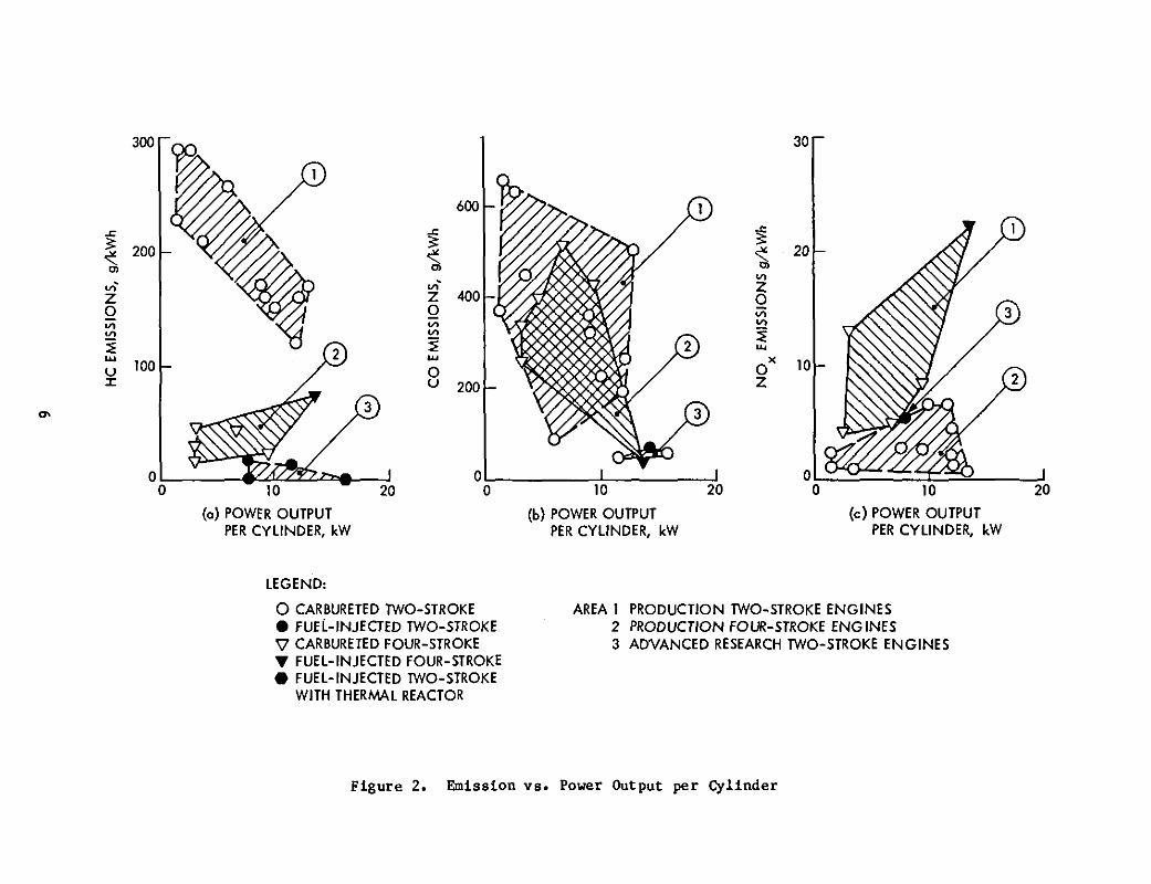
(a) Its fuel efficiency is excellent, exceeding that of a directinjection diesel at part load (see Figure la) while exhibitingemissions that are acceptable without after treatment (Figure2) and are excellent if used in conjunction with a thermalreactor.
(b) Having no valves, the advanced two-stroke engine is simple indesign and its service needs and production cost are low. Itis also eKtremely attractive from the packaging standpoint because it occupies only one-third of the volume (see Figure lb)and is more than 50% lighter (see Figure lc) than a conventional or advanced four-stroke engine of comparable performance.
3
Table 2. Comparison of Engine Design and Performance Criteria
tlternd eo.bUltionEngln..
OiuelsIndirect Injection'Naturaly A.pirated Iraytoa 5tirUna:
(TurbochU8"d)
Rabbit cr-lOO Hod 1YW 0" 1mProduction "0 Re...rch En '"37/5000 75/68000 54/4000I.H.)
22 4.5 Pl 17.5
'" 200 ]0'260/30 3200/<100 2H/6lJ
1.20.05) 1.0 • 3.541.4(1.0 <1.0 1.64
10 498 .fA .fA
Direct injection 2350" turbtne 15 KPa1l1prove. liSle inlet te.perature Hydrogenand power output 2-,haft reSenerated (2117 p.Uby 15% Lo" NClII: cOI'buIUon
including g"aul
...SuzukiOECRe.e.reb En10.
ATAC'CALle.elrell En
Inter""t Co-eu.Uon En tne.
1Wt-871.su..0
Naturally A.plnted Four-SttonSpan-hnitton Engine
Audl 1700Audl/WVProduction
55/5000 88/6000 121/6.500 16/4S0Qlo 80/60001.7(4) 2.0(4 ) ).0(2) 0.372(1) 1.2(3)8.' II .., J. , '/A
m ]0' ]00268/6) 239/67 248/7532.0 42.7 66.3
1.0 .fA 0.'1.0 '/A 0.32
11 978 11 339 17 925
ContinuOUI Fuel In eetioR Pulle Fuel In ecHon
Currently in I Highly I Stratified I Rel1dud g•• StratUled duelule in etlperi-! turbulent I cOlIIbuttion! controlled vortex cOIlbua-_ntal hybricl I c(llllbuatloni I tionvehicles I I Dud fuel I Fuel injection
I I injection I PneulUtlc '~l
I I I Unthrottled Injel:.tlonI I O~l I operationI I ignition II I II I .1I !Prediction I
Engine Concept
Criteria
Relative Weight to Power bUo:Relative VoluM to Power Ratio
Engtne Du1&natlo-nDevClloper. RelleareherStatuI
Maxi..... Power 8SFC. a1kWhOpt. BSFC. &!kWh/l powerPower Concentration kW/
HaxhlUlll Power Output. kW/rfN/-.1n IDhplaC::Ment, (No. Cyl1nden. RotOf,b>lCo. re.,lon beio
Seed Ca ,bUlt kW x rev/lIlin
I Naturally Aapluted. Two-StrokeI I.oury Spuk-lanlt1on Enaine
i + --'P"."•.!.tjl'o'- !-'<I!W!!.""'''."-'L)-f------,------ --"-===="---I MIIy II k1cardo I
R"
-Relative to copventlonal lov-c(lIIIpre,.ion-r.tlo, four-stroke. spark-ignition ell&ine.bRotary (Wankel) Engine.
z
r---. z
_ _ o o
z ." _ zO_ "oz o _ = <_ _ __
§ -
>.7 _o _ oz__o=Z e= -'_ _ 7 ,.,_,o _ <a z_ z o o
m -- _ 0 0_- < _ _ _,_
_: _ E z _ _ _ -- 8 _ __ o
0_ _ z: _ _ o__o _-:zZO_o. ,_°X_ - _- _"X o o_o_ __ ? - , :_ .- .-. ,
. 1 o o_ - - _ _ < Z _o._ ___,u_ _ _< _ '_._ _< > _< o
_> Z I I < {3 u
0.1-- - "--i '< --
I-,.4
0.0 _ _ . 0 - r._
(o) (b) (c)OPTIMUMBRAKE-SPECIFIC SPECIFICOVERALLVOLUME,JVkW SPECIFICWEIGHT,kg/kWFUELCONSUMPTION, kg/kWh
2010(c) POWER OUTPUT
PER CYLINDER, kW
10 20
(b) POWER OUTPUTPER CYLINDER, kW
0~__-''''£J4..<..i<..''-L'''~--:-'
o 10 20(0) POWER OUTPUT
PER CYLINDER, kW
300 30
..<: ..<: ~3: 3:
~200 ~ ~
20Cl
"I'"I
"I' ZZ Z 400 00 Q V;"I "I VI"I VI ~~ 2 ~ ....w .... Xu 100 0 0 10:r U 200 Z
'"
LEGEND:
o CARBURETED TWO-STROKE• FUel-INJECTED TWO-STROKE'\l CARBURETED FOUR-STROKE... FUEL-INJECTED FOUR-STROKE• FUEL-INJECTED TWO-STROKE
WITH THERMAL REACTOR
AREA 1 PRODUCTION TWO-STROKE ENGINES2 PRODUCTION FOUR-STROKE ENG INES3 ADVANCED RESEARCH TWO-STROKE ENGINES
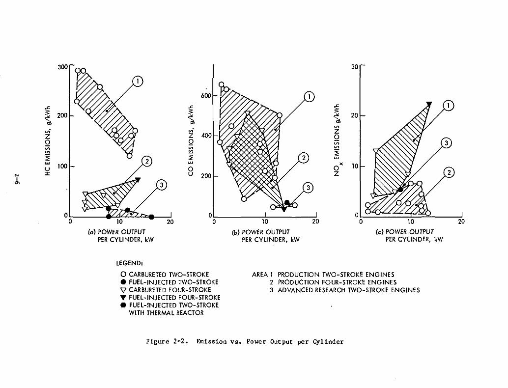
Figure 2. Emission vs. Power Output per Cylinder
(c) The stop-start capability of the advanced two-stroke engine isexcellent, delivering full power instantly without a warmup.Because of its low compression ratio (7.5:1) and the absenceof valve mechanisms, its motoring power is less than half thatrequired for four-stroke engines, which translates into lowtransient energy losses and improved vehicle fuel economy. Inconjunction with an advanced load-dependent metered injectionof the lubricant, its low compression ratio (7.5:1) translatesalso into a long service life under stop-start operatingconditions. Combining this low compression ratio with ahigh degree of internal turbulence allows this engine to betolerant of poor fuel quality (octane).
(2) The (Wankel-type) rotary engine should also be considered forhybrid-vehicle application, despite the fact that its fuel efficiency is not competitive with other candidate engines (see Figurela) because its packaging advantages (see Figure lb) are excellent. Its high speed capability (see Table 2) would permit it tobe coupled directly to and/or integrated with a high-speed alternator. In this case, the elimination of the gear losses wouldcompensate for its lack of fuel efficiency when compared withalternatives that must be geared to the alternator.
(3) Advanced high-compression, four-stroke piston engines have goodfuel efficiency (see Figure la), but they are expected to have NOx emission problems because of higher process tern.peratures and impaired catalytic converter efficiency. In hybrid stop-startoperation the catalytic converter does not reach its full steadystate efficiency (see Reference 3). The motoring power requirementsof high-compression-ratio engines are estimated to be 50% higherthan those of current four-stroke engines and 300% higher thanthose of advanced two-stroke and rotary engines. This fact willreduce their otherwise excellent fuel efficiency in stop-startoperation. The effects of stop-start operation on engine servicelife will also be more pronounced with a high-compress ion-ratiopiston engine.
(4) Free-piston, spark-, and compression-ignition engines (see Figurela) are attractive in terms of fuel efficiency, packaging, andvibration when coupled with a linear alternator for batterycharging. Because of their capability to produce high compressionratio at low friction losses, they are well suited for the implementation of diesel combustion and of spark-ignited combustionwith the use of alcohols or ammonia. If linear alternators showpotential for HV application, additional development of free-pistonengines should be considered because of their ability to enhancefuel econ any.
(5) Based on established criteria, external-combustion Brayton (gasturbine) and Stirling engines have no potential for most hybridvehicle applications because of their inherent inability to be used
7
in rapid start-stop operation. Because of small-size effects,Brayton engines cannot be considered for power outputs below 75 kW;otherwise, they would have a potential for battery charging.
(6) The indirect-injection diesel loses out against other candidateengines in all areas (see Figure 1), including that of fuelefficiency. With direct injection, the diesel will be the mostfuel-efficient, internal-combustion engine available when comparedin terms of grams per kilowatt hour. However, because of its needfor preheating prior to start and its high cranking power requirements, the diesel engine needs to idle instead of being turnedoff. Although its idle fuel-flow rate is only 20 to 25% that ofspark-ignition engines, this requirement will reduce its actualfuel efficiency to some degree in most hybrid applications. Theidling diesel is an attractive alternative because of hybridaccessory power and heating, which are still unresolvE'd problemswith heat-engine stop/start operation.
C. RECOMMENDATIONS
Because of the great potential for improvements in. HV fuel economy,weight, and other factors affecting overall HV Viability, further researchis recommended. The follOwing efforts consider the unique HV requirementsin a prioritized sequence:
(1) Based on available information and the conclusions drawn by thisstudy, it is recommended that heat-engine development be pursuedas indicated in Table 3, which is grouped by hybrid powertrainconcepts. The two-stroke engine is the primary choice of allpowertrain concepts considered, wi th the exception of a primaryheat-engine-powered hybr id car with an auxiliary electric powertrain that requires more than 50 kW of heat-engine power. Thelow-compression, four-stroke, spark-ignition engine is the bestbackup choice if it is equipped with a fuel-injection system andaccessories developed to cope with the special requirements forstop-start operation. The free-piston diesel and the alcoholfueled, spark-ignition, free-piston engines have an at tractivepotential for battery charging with a linear alternator. Thispotential should be re-evaluated, taking the latest technologyand innovative concepts into account.
(2) The study further recOClmends follow-on analysis and experimentationwith candidate engine concepts that are believed necessary tosupport the selection of a heat-engine concept for future hybridvehicles. This effort should concentrate on the determination andevaluation of properties of specific interest to HVs that usuallycannot be supplied by the heat-engine developer. The rationale andobjectives of these recommendations are outlined in detail inSection V of this report.
8
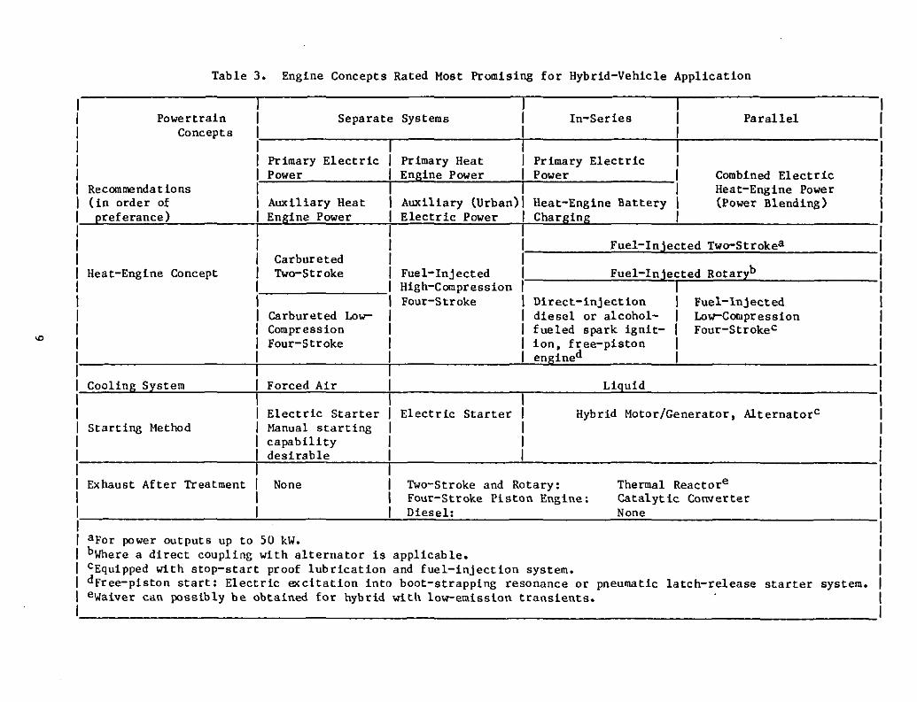
Table 3. Engine Concepts Rated Most Promising for Hybrid-Vehicle Application
PowertrainConcepts
Separate Systems In-Series Parallel
Fuel-Injected Two-Strokea
Fuel-Injected Rotaryb
Recommendations(in order ofpreferance)
Heat-Engine Concept
Cooling System
Primary ElectricPower
Auxiliary HeatEngine Power
CarburetedTwo-Stroke
Carbureted LowCompressionFour-Stroke
Forced Air
Primary HeatEngine Power
Auxiliary (Urban)Electric Power
Fuel-InjectedHigh-CompressionFour-Str oke
Primary ElectricPower
Heat-Engine BatteryCharging
Direct-injectiondiesel or alcoholfueled spark ignition, free-pistonengined
Liquid
Combined ElectricHeat-Engine Power(Power Blending)
Fuel-InjectedLow-CompressionFour-Strokec
Starting MethodElectric StarterManual startingcapabilitydesirable
Electric Starter Hybrid Motor/Generator, AlternatorC
Exhaust After Treatment None Two-Stroke and Rotary:Four-Stroke Piston Engine:Diesel:
Thermal ReactoreCatalytic ConverterNone
aFor power outputs up to 50 kW.bWhere a direct coupling with alternator is applicable.CEquipped with stop-start proof lubrication and fuel-injection system.dFree-piston start: Electric excitation into boot-strapping resonance or pneumatic latch-release starter system.eWaiver can possibly be obtained for hybrid with low-emission transients.
D. SUMMARY OF CURRENT HEAT-ENGINE RESEARCH AND DEVELOPMENT
1. Four-Stroke, Spark-Ignition Piston Engines
Concentrated efforts are being made by well-known developers toimprove the fuel efficiency of the atmospherically aspirated, four-stroke,spark-ignition engine by raising its compression ratio and introducing highlyturbulent, squish-flow agitated combustion to inhibit knocking. Fuel efficiency improvements of up to 15% and increased power output per unit displacement of up to 30% have been demonstrated. Developers are hopeful that highcompression engines can be marketed by 1985 as an option. Flame erosion ofthe pistons, closer head tolerances, and associated higher production costare the pacing problems to be resolved.
2. Four-Stroke, Spark-Ignition (Wankel) Rotary Engines
State-of-the-art, rotary, four-stroke, spark-ignition engines areequivalent to four-stroke piston engines of current low-compression (8.5 to8.7:1) design in fuel efficiency and emissions. This has been achievedprimarily by improving the rotor seals, raising the compression ratio to 9:1,and introducing stratified combustion brought about by dual fuel injectionand ignition. However, with these measures the fuel efficiency potential ofrotary engines is essentially exhausted, with rotor sealing and combustionchamber configuration (high surface to volume ratio) being the primary limiting factors. They are, therefore, incapable of competing with high-compression four-stroke piston engines in the future. A certain potential stillexists to improve the already excellent speed potential of rotaries (see Table2) by means of lift-off seals, which still remain to be developed. The majordevelopers of advanced fuel-injected, rotary (Wankel) engines (Audi-NSU, andCurtiss-Wright), have reassessed their goal of (some day) dominating the automotive market and are now looking for other fields of application where thepackaging advantages, high-speed capability, and smoothness of the rotaryconcept would be of overriding importance. According to dealer information,Mazda will market a fuel-injected rotary engine as an option in 1984 modelcars.
3. Diesel Engines
The uncertainties associated with diesel emission legislation inEurope and the United States as well as declining diesel sales because ofthe diminishing pr ice advantage of diesel fuel relative to gasoline stronglyinhibit the incentive to further improve the small automotive indirect injection diesel engine. A proposed quiet, direct-injection, high-speed dieselengine with an improved (by another 15%) fuel efficiency was initiated by BMWand Steyer in the early 1980s but was shelved because of economical reasonsand the technical difficulties encountered.
4. Two-Stroke, Spark-Ignition Piston Engines
Because they were forced out of the vehicular market more than tenyears ago by emission legislation, the developers of two-stroke engines are
10
making a quiet effort to regain their place in the market. All vehicularapplications-oriented research with two-stroke engines is concentrated inJapan, Switzerland, Ireland, and Australia and has produced significantresults. The emission problem of two-stroke engines has been essentiallyeliminated by introducing cylinder fuel injection and stratified combustiontechniques that allow the engine to be operated unthrottled over a wideoperating range. The part-load fuel efficiencies independently demonstratedwith advanced two-stroke engines in Australia, Japan, and Europe are equivalent to or better than those of an automotive 'diesel of current design. Thepacing problem is that 'of a high-speed, fuel-injection system capable ofreliably handling small amounts of fuel. Developers are confident that thetwo-stroke engine in the advanced form will make a comeback in the smallvehicle market in 3 to 5 years. Ongoing R&D work with two-stroke engines inthe United States is primarily concentrated on improving the performance ofcarbureted outboard marine and utility engines.
5. External-Combustion Engine
R&D work with automotive Brayton and Stirling engines is concentrated in the United States but is progressing slowly because of reducedgovernment funding. The use of high-temperature materials (ceramics) inthe Brayton engine, and of high-pressure hydrogen with its associated sealing difficulties in the Stirling engine, are the pacing problems. There islittle hope that any of the external combustion engines will mature by theend of this .decade.
6. Free-Piston Engine
After a long period of dormancy, sporadic project work and experimentation with diesel, Otto and Stirling free-piston engines have resurfacedin Europe and the United States, using new technology and design approaches.A power output of 75 kW at 5000 cycles per minute has recently been demonstrated by Stelzer in Germany with a spark-ignited, carbureted, free-pistonengine.
In conjunction with a f1irectly coupled linear alternator, free-pistonengines are believed to have potential for the generation of electricalenergy over a wide range of power outputs from 3 to 700 kW because of theirsimplicity and capability of producing high compression ratios with lowinternal friction losses. If the predicted speeds can be achieved (up to30,000 cyCles per minute), a free-piston, linear alternator power unit w11lbe very attractive for the generation of electrical energy in hybrid vehiclesin terms of weight and packaging. According to predictions, free-pistonengines are capable of delivering up to 30% more power at the same fuelconsumption as a crankshaft engine using an identical thermodynamic cycle.However, none of the recent efforts has progressed beyond proving the validityand feasibility of the concept.
11

Part TwoEvaluation of Heat Engines

SECTION 1
METHODOLOGY FOR HYBRID VEHICLE ENGINE EVALUATION
Hybrid vehicles use a heat engine in combination with an electricalpowertrain that derives its energy from a rechargeable battery. The designobjective is to reduce petroleum fuel consumption and air pollution. Thepossible combinations and uses of a heat engine' in a hybrid vehicle (HV) aremany and depend on mission objectives, drive cycle, and minimum vehicle performance requirements. The rationale for heat engine selection is, therefore,difficult to define in general terms, and each individual case must be judgedseparately. The scenario of hybrid-vehicle missions, powertrain arrangements, and related rationale for the selection of heat engines can bedivided into four major categories:
A. PRIMARY ELECTRIC CAR WITH AUXILIARY HEAT ENGINE
The car is used primarily in the electric mode for short-range urbanuse while the heat engine is only used when the battery has been completelydischarged. In this case, simplicity and low cost, engine reliability,low service needs, and manual starting capability have priority over fuelefficiency and emissions.
B. PRIMARY HEAT-ENGINE-DRIVEN CAR WITH AUXILIARY ELECTRIC POWERTRAIN
Hybrid-vehicle developers in Europe (Reference 1-1) envision a vehiclethat is pr imarily heat-engine-driven. It is designed to depend on batterypower only when operating in metropolitan areas where the use of heat enginesmay be banned in the future due to pollution constraints. The heat-enginedesign objectives and selection rationale for a hybrid vehicle of such aconcept are essentially the same as those that govern the engine design andselection of conventional, primarily heat-engine-powered cars, i.e., compliance with minimum performance, drive-cycle fuel economy and emissionsrequirements, packaging advantages, weight, and noise are the primary criteriafor the selection of the heat engine. In hybrids of this type, the engine issized to provide for the power needed to meet vehicle performance requirementswithout the help of the electric motor.
C. HEAT-ENGINE RECHARGEABLE PRIMARY ELECTRIC CAR
For an in-series arrangement in which the heat engine has only the taskof charging the battery whenever the state of charge has dropped to a tolerable minimum, the rationale for the selection of a heat engine is in essencethe same as those for a mobile, standby generator, i.e, sure-start capability,low service needs, low noise, weight, and a low hourly fuel consumption at aconstant speed are the primary criteria for heat-engine selection. Theengine must be sized to meet maximum charge power requirements in an operatingpoint near, or at its best, specific fuel consuQption.
1-1
D. TRUE HYBRID HEAT-ENGINE/ELECTRIC CAR
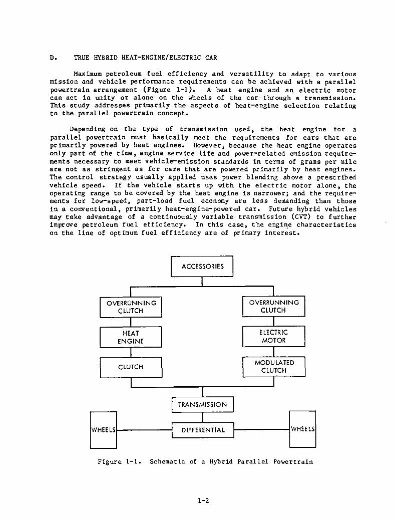
Maximum petroleum fuel efficiency and versatility to adapt to variousmission and vehicle performance requirements can be achieved with a parallelpowertrain arrangement (Figure 1-1). A heat engine and an electric motorcan act in unity or alone on the wheels of the car through a transmission.This study addresses primarily the aspects of heat-engine selection relatingto the parallel power train concept.
Depending on the type of transmission used, the heat engine for aparallel powertrain must basically meet the requirements for cars that areprimarily powered by heat engines. However, because the heat engine operatesonly part of the time, engine service life and power-related emission requirements necessary to meet vehicle-emission standards in terms of grams per mileare not as stringent as for cars that are powered primarily by heat engines.The control strategy usually applied uses power blending above a ,prescribedvehicle speed. If the vehicle starts up with the electric motor alone, theoperating range to be covered by the heat engine is narrower; and the requirements for low-speed, part-load fuel economy are less demanding than thosein a conventional, primarily heat-engine-powered car. Future hybrid vehiclesmay take advantage of a continuously variable transmission (CVT) to furtherimprove petroleum fuel efficiency. In this case, the engi~e characteristicson the line of opticum fuel efficiency are of primary interest.
ACCESSORIES
II I
OVERRUNNING OVERRUNNING
CLUTCH CLUTCH
I IHEAT ELECTRIC
ENGINE MOTOR
I ICLUTCH
MODULATEDCLUTCH
I II
TRANSMISSION
IWHEELS
IDIFFERENTIAL
I WHEELSI I
Figure 1-1. Schematic of a Hybrid Parallel Powertrain
1-2
The efficient use of the parallel powertrain concept requires that theheat engine be fired up on driver or battery demand and be shut off if drivecycle vehicular power demands can be satisfied with the electric motor alone,and when no battery charging is required. To satisfy this requirement, theheat engine must have the capability of starting and delivering full poweralmost instantly. It must be compatible with a repeated stop-start operationin short time intervals (seconds) at low ambient temperatures throughout theengine service life.
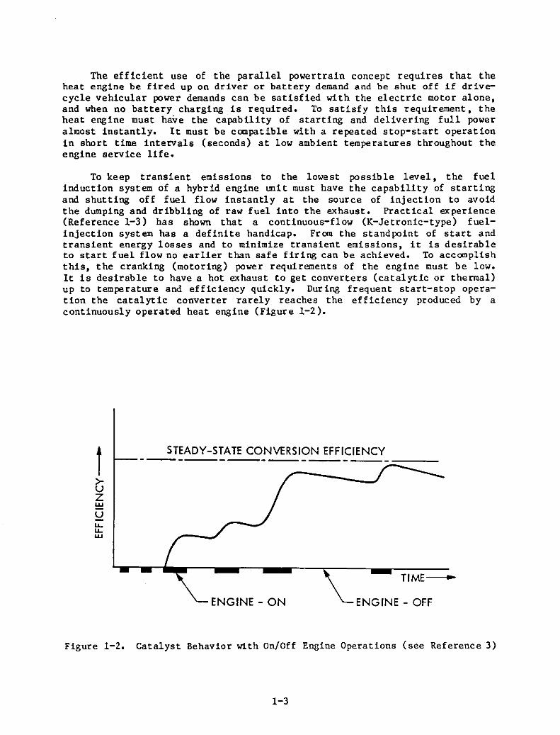
To keep transient emissions to the lowest possible level, the fuelinduction system of a hybrid engine unit must have the capability of startingand shutting off fuel flow instantly at the source of injection to avoidthe dumping and dribbling of raw fuel into the exhaust. Practical experience(Reference 1-3) has shown that a continuous-flow (K-Jetronic-type) fuelinjection system has a definite handicap. From the standpoint of start andtransient energy losses and to minimize transient emissions, it is desirableto start fuel flow no earlier than safe firing can be achieved. To accomplishthis, the cranking (motoring) power requirements of the engine must be low.It is desirable to have a hot exhaust to get converters (catalytic or thermal)up to temperature and efficiency quickly. During frequent start-stop operation the catalytic converter rarely reaches the efficiency produced by acontinuously operated heat engine (Figure 1-2).
t>UZw
uu.u.w
STEADY-STATE CONVERSION EFFICIENCY- --;..:::::::::::--
TIME •
ENGINE - ON ENGINE - OFF
Figure 1-2. Catalyst Behavior with On/Off Engine Operations (see Reference 3)
1-3
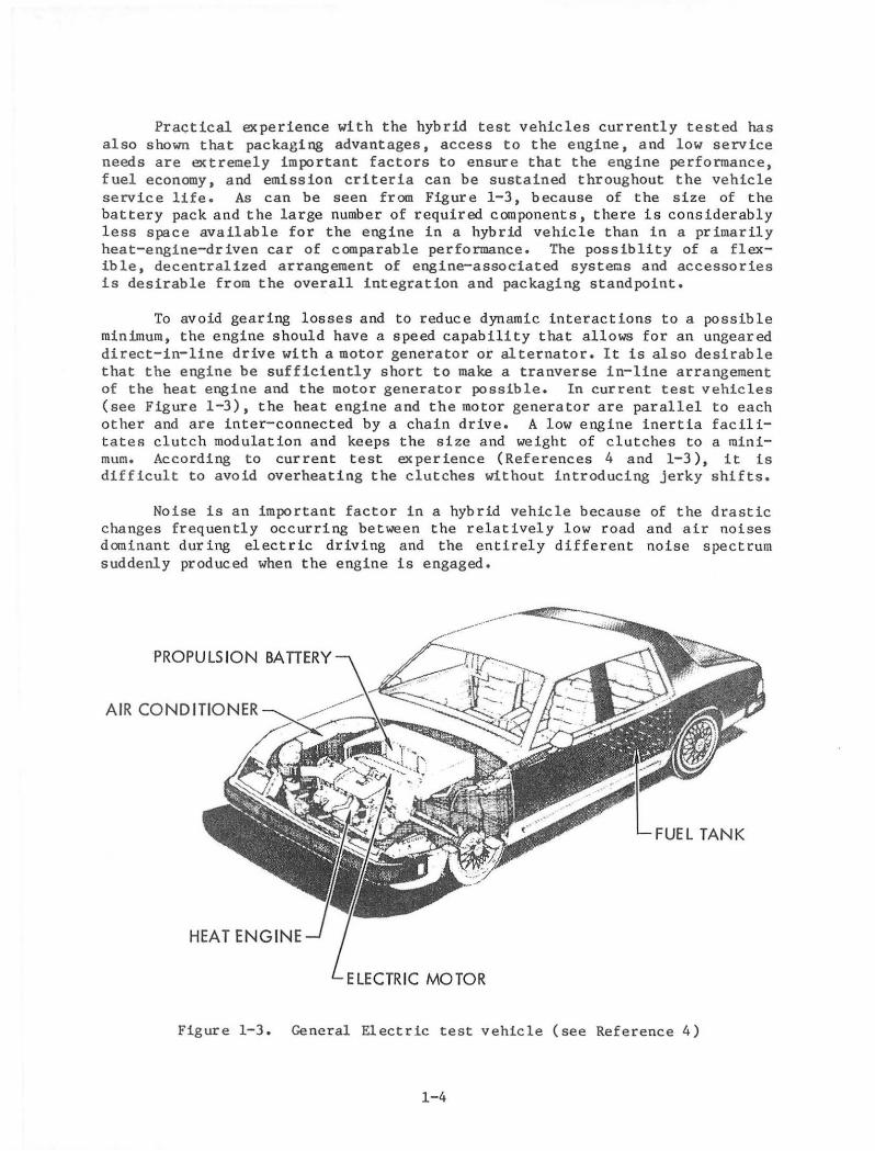
Practical experience with the hybrid test vehicles currently tested hasalso shown that packaging advantages, access to the engine, and low serviceneeds are extremely important factors to ensure that the engine performance,fuel economy, and emission criteria can be sustained throughout the vehicleservice life. As can be seen from Figure 1-3, because of the size of thebattery pack and the large number of required components, there is considerablyless space available for the engine in a hybrid vehicle than in a primarilyheat-engine-driven car of comparable performance. The possiblity of a flexible, decentralized arrangement of engine-associated systems and accessoriesis desirable from the overall integration and packaging standpoint.
To avoid gearing losses and to reduce dynamic interactions to a possibleminimum, the engine should have a speed capability that allows for an ungeareddirect-in-line drive with a motor generator or alternator. It is also desirablethat the engine be sufficiently short to make a tranverse in-line arrangementof the heat engine and the motor generator possible. In current test vehicles(see Figure 1-3), the heat engine and the motor generator are parallel to eachother and are inter-connected by a chain drive. A low engine inertia facilitates clutch modulation and keeps the size and weight of clutches to a minimum. According to current test experience (References 4 and 1-3), it isdifficult to avoid overheating the clutches without introducing jerky shifts.
Noise is an important factor in a hybrid vehicle because of the drasticchanges frequently occurring between the relatively low road and air noisesdominant during electric driving and the entirely different noise spectrumsuddenly produced when the engine is engaged.
PROPU LS ION BAITERY
HEAT ENGINE
FUEL TANK
ELECTRIC MOTOR
Figure 1-3. General Electric test vehicle (see Reference 4)
1-4
SECTION II
STATUS REVIEW OF VARIOUS HEAT ENGINE CONCEPTS
Engine concepts under consideration are internal and external combustionengines of advanced design that have been primarily conceived with vehicularuse in mind. Only those concepts most representative for a specific conceptare discussed. The major design and rating criteria for these engines aresummarized in Table 2-1. The data and discussions are based on open literature and information obtained from personal communication with the indicatedsources. Over 100 papers were reviewed and 19 sources were contacted forconsultation. The development status, projections, potential for improvement,and pacing problems associated with concepts under consideration are discussedin the following subsections.
A. SPARK-IGNITION ENGINES
1. Four-Stroke Piston Engines
For the projected ten-year time frame the three-way, catalystcontrolled, continuous-flow electronically fuel-injected, naturally aspirated, four-stroke, spark-ignition piston engine will dominate the marketfor passenger cars that are primarily powered by heat engines. Multi-sourcefuel injection has brought an improvement of about 15% over the single-sourcecarbureted or fuel-injected engine by significantly reducing the unevendistribution to the cylinders.
A few developers (Saab, Buick, Audi, and others) offer turbocharged,electronically knock-controlled power plants. The relative high cost for themaintenance and repair of turbocharged engines, however, inhibit the broadacceptance of turbocharging by the general public. The high speed and powerboost potential of the turbocharged engine is only attractive to a smallnumber of users. Usually there are no economical advantages although somedevelopers claim that fuel economy advantages can be shown with wastegatedturbochargers sized for maximum torque at medium engine speeds, with a reducedrear-axle ratio and an undersized, lighter engine. Although turbocharger laghas been greatly improved during recent years due to lightweight rotor designand the application of wastegate control strategy, costs and upkeep remain adeterrent for the users of a car that operates predominantly at low to mediumspeeds.
Besides general improvements that are currently being made in enginedesign, materials, components, and production technology, some major developments are being made in the improvement of the naturally aspirated, sparkignition engine by increasing its breathing capability and compression ratio.While the potential to further improve the breathing capability obtainablewith two poppet valves appears to be fairly exhausted, a sizable potential toimprove partload fuel economy still exists by increasing the cocpressionratio. Special precautions, however, have to be taken to inhibit knocking.
2-1
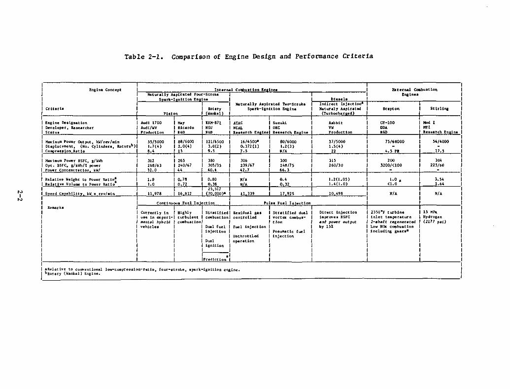
Table 2-1. Comparison of Engine Design and Performance Criteria
NI
N
Engine Concept
Criteria
Engine Duign.tionDeveloper, ResearcherStatuI
Hax1lllum Power Output, kWlrev/min IDisplacement. (No. Cylinders, Rotorsb )ICo resaion Ratio
H.uigum Power 8SFC, g/kWhOpt. 8SFC. g/kWh/:f: powerPower Concentration kW/
Relative Weight to Power Ratio:Relative Volume to Power Ratio
Seed Ca abilit kW x rev/min
Remark.
InterMI Collbultion En lnea b: t ernal Combuat iob.Na.turally Aaplrated Four-Stroke Ena:ine.
Sparlt-Ignition Engine DteullI Naturally Alpirated TlIo-Stroke Indirect Injection-I lotny Spark-Ignition Engine Naturaly .bpirated Brayton SUrUna
Phton I (Wanhl) (Turbocharged)I I
Audl 1700 I lI.oy I 1tIQt-81l ATAC I Suzuki Rabbit Gr-lOO Hod [Audl/WV I Ricardo I .su .eAL I DEC VW ODA H"Production I ",0 ... le.earch En I .. leeeareh En In. Production ... R.llurdt tn In•
55/5000 I 88/6000 121/6500 16/45001' 80/6000 37/5000 75/68000 54/40001.1(4 ) I 2.0(4) ].0(2) 0.372(1) 1.2(] ) 1.5(4 )
••• n .., 7.' .,. 22 4.S PR 17.5
Jl2 '" 360 3D' 300 31' 200 lo.268/61 240/67 305/15 239/67 248/15 260/30 3200/<100 225/60)2.0 .. 40.4 42.7 66.3
1.0 .,. 0.' 1.2(1.05) l.O. 3.541.0 .,. 0.32 1.4(1.0) (1.0 1.64
11 978 11 339 17925 10 498 .,. Nt•
ContlnllOUl Fuel In eetion Pulle Fuel In eetion
Currently in I Highly I Stratified I Realdual gaa Stratified dual Direct injection 2)~O·F turbine IS HPaUSl1l in ex peri-I turbulent I cOIllbusrion I controlled vortell cOIIIbus- illprovea 8St'C inlet telllperature Hydrogenmelle"l hybl"1d I cOlIIbustioni , tion and power output 2-ahatt regenerated (2117 pit)vehicles I I Dual fuel I Fuel injection by IS% Low NOK cOIIIbustion
I I injection I Pneumatic f~l includina gearsa
I 1 I Unthrottled injectionI I D~I I operationI 1 ignition II I II I .1I IPredlctlon I
IlReiative to conventional lov-cOGlpression-r,tio. four-stroke, spark-ignition engine.bRoury (Wankel) Engine.
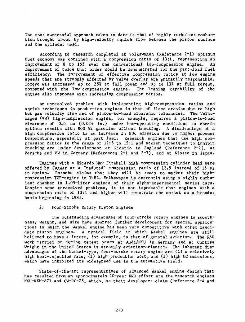
The most successful approach taken to date is that of highly turbulent combustion brought about by high-velocity squish flow between the piston surfaceand the cylinder head.
According to research completed at Volkswagen (Reference 2-1) optimumfuel economy was obtained with a compression ratio of 13:1, representing animprovement of 8 to 15% over the conventional low-compression engine. Animprovement of twice that order could be demonstrated for the part-load fuelefficiency. The improvement of effective compression ratios at low enginespeeds that are strongly affected by valve overlap are primarily responsible.Torque was increased up to 25% at full power and up to 13% at full torque,compared with the low-compression engine. The leaning capability of theengine also improves with increasing compression ratios.
An unresolved problem with implementing high-compression ratios andsquish techniques in production engines is that of flame erosion due to highhot gas velocity flow and of piston-to-head clearance tolerances. The Volkswagen (VW) high-compression engine, for example, requires a piston-to-headclearance of 0.6 mm (0.024 in.) under hot-operating conditions to obtainoptimum results with RON 92 gasoline without knocking. A disadvantage of ahigh compression ratio is an increase in NO>< emission due to higher processtemperature, especially at part load. Research engines that use high compression ratios in the range of 12:5 to 15:1 and squish techniques to inhibitknocking are GIlder development at Ricardo in England (Reference 2-2), atPorsche and VW in Germany (References 2-1 and 2-3), and at Nissan in Japan.
Engines with a Ricardo May Fireball high compression cylinder head wereoffered by Jaguar at a "reduced" compression ratio of 12.5 instead of 15 asan option. Porsche claims that they will be ready to market their highcompression TOP-engine in 1984. Volkswagen is currently using a highly turbulent chamber in l.05-liter engines of their alpha-experimental series cars.Despite some unresolved problems, it is not improbable that engines with acanpression ratio of 13:1 and higher will penetrate the market on a broaderbasis beginning in 1985.
2. Four-Stroke Rotary Piston Engines
The outstanding advantages of four-stroke rotary engines in smoothness, weight, and size have spurred further development for special applications in which the Wankel engine has been very competitive with other candidate piston engines. A typical field in which Wankel engines are stillbelieved to have a future, for example, is that of general aviation. The R&Dwork carried on during recent years at Audi/NSU in Germany and at CurtissWright in the United States is strongly aviation-oriented. The inherent disadvantages of the Wankel-type, four-stroke rotary engine are (1) a relativelyhigh heat-rejection rate, (2) high production cost, and (3) high HC emissions,which have inhibited its widespread use in the automotive field.
State-of-the~art representat ives of advanced Wankel engine design thathas resulted from an approximately 20-year R&D effort are the research enginesNSU-KKM-87l and CW-RC-75, which, as their developers claim (Reference 2-4 and
2-3
2-5), are equivalent to currently designed fuel-injected piston engines infuel economy, emissions, and service life. The improvements have been achievedprimarily by the introduction of dual ignition and two-stage, continuous-flowfuel ignition, stratified combustion, and by an improved seal design capableof producing higher compression ratios (up to 9: 5) at a reduced low-speedblow-by. Housing coolant flow has been improved, rotors are now oil-cooled,and advanced metallurgical methods are used to treat housing interior surfacesfor increased wear resistance.
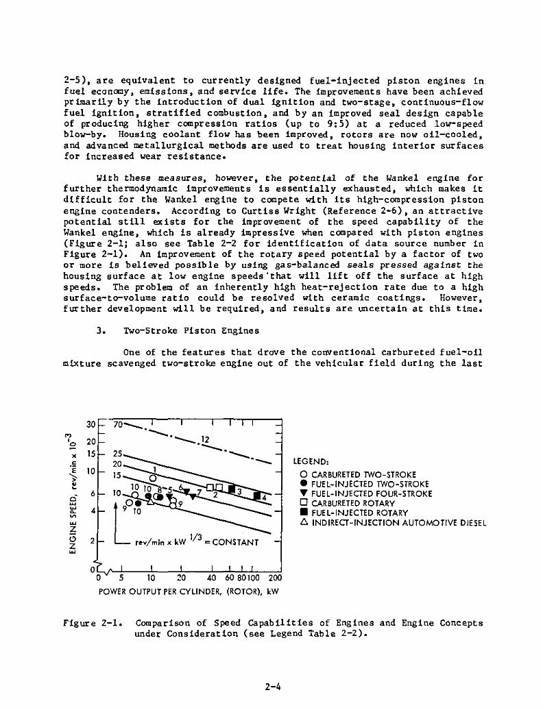
With these measures, however, the potential of the Wankel engine forfurther thermodynamic improvements is essentially exhausted, which makes itdifficult for the Wankel engine to compete with its high-compression pistonengine contenders. According to Curtiss Wright (Reference 2-6), an attractivepotential still exists for the improvement of the speed capability of theWankel engine, which is already impressive when compared with piston engines(Figure 2-1; also see Table 2-2 for identification of data source number inFigure 2-1). An improvement of the rotary speed potential by a factor of twoor more is believed possible by using gas-balanced seals pressed against thehousing surface at low engine speeds' that will lift off the surface at highspeeds. The problem of an inherently high heat-rejection rate due to a highsurface-to-volume ratio could be resolved with ceramic coatings. However,further development will be required, and results are uncertain at this time.
3. Two-Stroke Piston Engines
One of the features that drove the conventional carbureted fuel-oilmixture scavenged two-stroke engine out of the vehicular field during the last
30M'0 20
15
6
4
2
70__
"- "__ 12
"--"--'- LEGEND:
o CARBURETED TWO-STROKE• FUEL-INJECTED TWO-STROKE~ FUEL-INJECTED FOUR-STROKEo CARBURETED ROTARY• FUEL-INJECTED ROTARYt::. INDIRECT-INJECTION AUTOMOTIVE DIESEL
o~O-.../'-~5!--~10:---;f;20:---4:':0:--6;':;0:-:8:'::071O~0:-:2:-:-:00
POWER OUTPUT PER CYLINDER, (ROTOR), kW
Figure 2-1. Comparison of Speed capabilities of Engines and Engine Conceptsunder Consideration (see Legend Table 2-2).
2-4
Table 2-2. Identification of Data Points by Numberin Figure 2-1, 2-3, 2-4
No.
1234567
89
101112
Researcher or Developer
Yamaha Uotor CompanyAudi NSUAudi NSUCurtiss Wright CorporationAudi!lay FireballPorsche
Swiss Instutute of TechnologyaNippon Clean Air LabFuji Heavy IndustryVolkswagenCurtiss Wright Corporation
Location
JapanWest GermanyWest GermanyUnited StatesWest GerIJanySwi tzerlandWest Germany
Swit zerlandJapanJapanWest GermanyUn ited States
Engine Type
RacingRC2-60, ProductionK~~-B77, Research2-75, Research1.74-1, ProductionResearchTOP (Thermodynamically OptimizedPorsche) R&DResearchResearchResearchResearchProductionRotary Researchwith Lif t-offSeals (Estimate)
a Eidgenoessische Technische Hochschule.
decade was an extremely high emission of carbon mo[)ox ide and unburned hydrocarbons (Figures 2-2 and 2-3) which produced sr:loke and an unpleasant odor.The scavenging of large amounts of fuel into the exhaust (short-circuiting)and the relatively large amounts of oil (1:20) mixed into fuel to satisfyworst-case lubrication requirements is primarily responsible for these conditions in carbureted engines. As shown in Figure 2-4(a,b), these conditionsalso resulted in the poor fuel economy of carbureted two-stroke engines compared to four-stroke engines. Fuel economy and hydrocarbons emissions areclosely related.
These deficiencies, which have been considered "inherent" for a longtime, have now been overcome as the result of research conducted in Japan,Switzerland, and Australia. Better fuel efficiencies than those for indirectinjection diesels as well as emissions comparable to those for four-strokeengines have been demonstrated with research fuel-injected, two-stroke engines(see Figures 2-2 and 2-4).
According to publications and personal communications with Japaneseresearchers (Reference 2-7), improvements demonstrated with Japanese researchengines have been achieved primarily by using cylinder fuel injection, carefully metering and minimizing the amounts of lubricating oil, and controllingcylinder charge with the amounts of residual gases in the cylinder with an
2-5
2010
(c) POWER OUTPUTPER CYLINDER, kW
30
10 20
(b) POWER OUTPUTPER CYLINDER, kW
o!:-------4IlLLI~~~t_---Jo 10 20
(0) POWER OUTPUTPER CYLINDER, kW
.c .c .c3: 3: 3:
~200
~ ~20
Cl
",' '"",' ZZ Z 400 Q0 Q '"'" '" '"'" '" ~~ ~ ww
100w x 10u 0 0
N :I: U 200 ZIa-
LEGEND:
o CARBURETED TWO-STROKE• FUEL-INJECTED TWO-STROKE'\1 CARBURETED FOUR-STROKE... FUEL-INJECTED FOUR-STROKE• FUEL-INJECTED TWO-STROKE
WITH THERMAL REACTOR
AREA 1 PRODUCTION TWO-STROKE ENGINES2 PRODUCTION FOUR-STROKE ENGINES3 ADVANCED RESEARCH TWO-STROKE ENGINES
Figure 2-2. Emission vs. Power Output per Cylinder
104
10
LEGEND:
Eo CARBURETED TWO-STROKE
Q.
103 • FUEL-INJECTED TWO-STROKE
Q.
o "UEL-INJECTED TWO-STROKEV>-
WITH THERtML REACTORZ0 '9' FUEL-INJECTED FOUR-STROKEV> ... FUEL-INJECTED FOUR-STROKEV>
:!: WITH CATALYTIC CONVERTERw
102 -- AT OPTIMUM BRAKE-SPECIFICu FUEL CONSUMPTIONJ:
A T MAXIMUM POWER
100
101
102
CO EMISSION, %
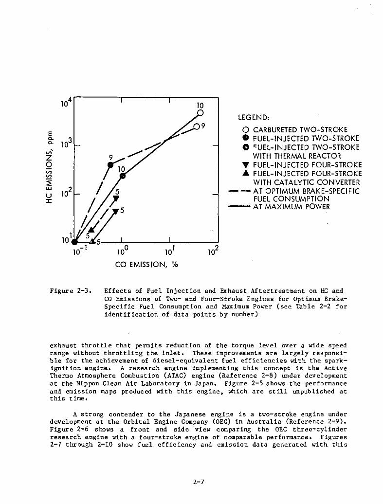
Figure 2-3. Effects of Fuel Injection and Exhaust Aftertreatment on HC andCO Emissions of Two- and Four-Stroke Engines for Optimum BrakeSpecific Fuel Consumption and Maximum Power (see Table 2-2 foridentification of data points by number)
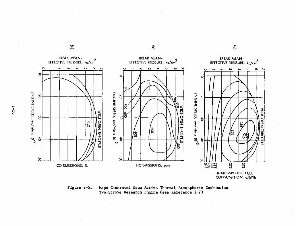
exhaust throttle that permits reduction of the torque level over a wide speedrange without throttling the inlet. These improvements are largely responsible for the achievement of diesel-equivalent fuel efficiencies with the sparkignition engine. A research engine implementing this concept is the ActiveThermo Atmosphere Combustion (ATAC) engine (Reference 2-8) under developmentat the Nippon Clean Air Laboratory in Japan. Figure 2-5 shows the performanceand emission maps produced with this engine, which are still unpublished atthis time.
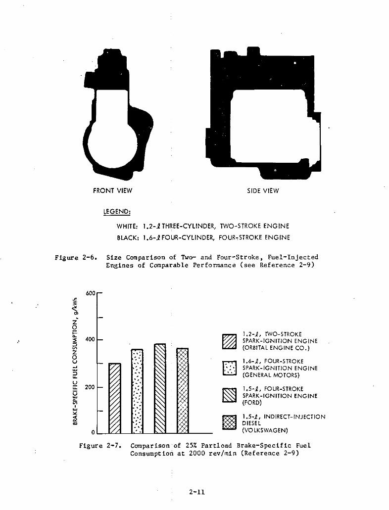
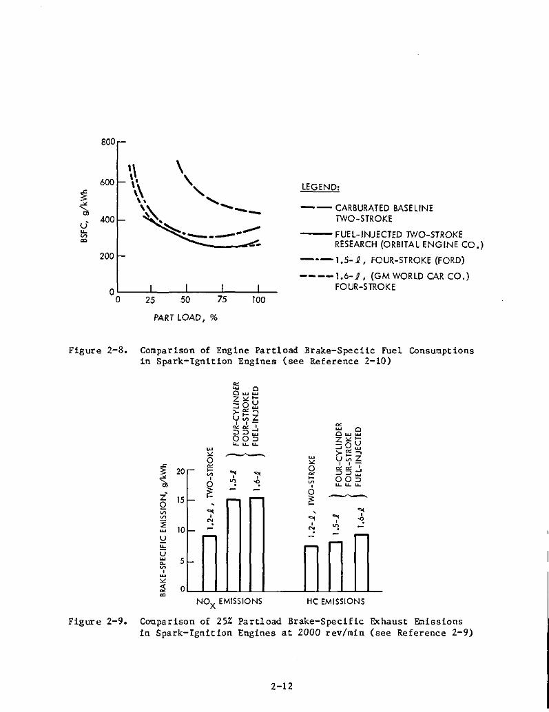
A strong contender to the Japanese engine is a two-stroke engine underdevelopment at the Orbital Engine Company (DEC) in Australia (Reference 2-9).Figure 2-6 shows a front and side view comparing the DEC three-cylinderresearch engine with a four-stroke engine of comparable performance. Figures2-7 through 2-10 show fuel efficiency and emission dal:a generated with this
2-7
10500r----,---,---,.----,---,
8
400
;E 300 ..c 3003:..lI.
~'dl11
U U·u.. "-VI 200 VI 200'" '"
NI
00100
o~-----=':_--f:_---;'::----:o:--___:_~o 20 40 60 80 100
(0) POWER CONCENTRATION FORMAXIMUM POWER, kW/l
LEGEND:
• FUEL-INJECTED ROTARY6. INDIRECT-INJECTION AUTOMOTIVE DIESELo CARBURETED TWO-STROKE• FUEL-INJECTED TWO-STROKEA FUEL-INJECTED TWO-STROKE WITH THERMAL REACTOR'Y FUEL-INJECTED FOUR-STROKE
100
O~-_::::_-____;"';:_--_;';:_--_;!;:::-____;~o 20 40 60 80 100
(b) POWER CONCENTRATION FOROPTIMUM FUEL EFFICIENCY, kW/l
AREA A - CARBURETED SINGLE-STROKEAREA B - FUEL-INJECTED TWO-STROKEAREA C - FUEL-INJECTED FOUR-STROKE
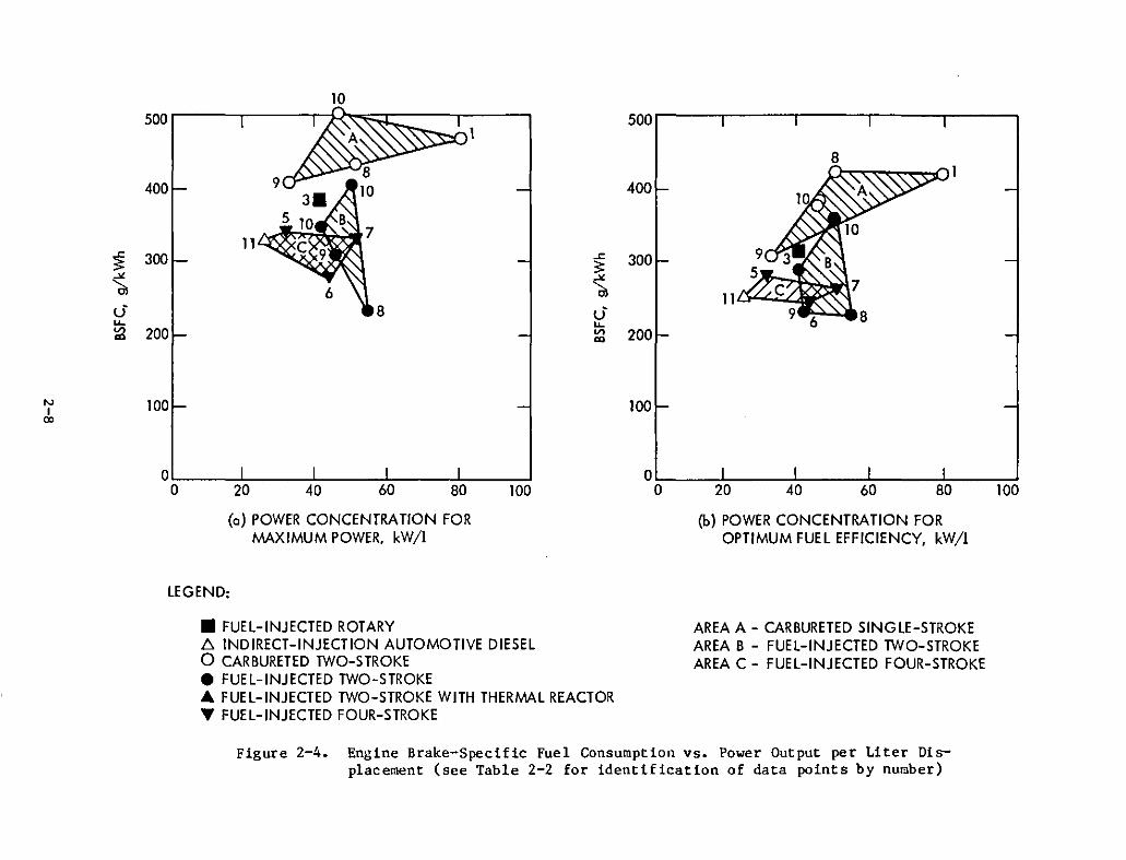
Figure 2-4. Engine Brake-Specific Fuel Consumption vs. Power Output per Liter Displacement (see Table 2-2 for identification of data points by number)
engine that have also not yet been published. As can be seen from Figure 2-11,the two-cycle engine's inherent instability at low speed is nonexistent,and the cycle-to-cycle variation achieved is comparable to those of foureight-stroke engines at lean conditions (>4). According to a presentationgiven by OEC at JPL on August 8, 1983, the "secret" of this extraordinaryperformance is a new dual-vortex stratified combustion process and a pneumaticfuel-injection system, described in Reference 2-10, that ensures propermetering and atomization of the fuel over a wide range of fuel flow rates andengine speeds. These measures together permit the operation of the engine.unthrottled, controlling load primarily with the fuel-to-air ratio. As is thecase with the Japanese ATAC engine, this improvement explains the achievementof a specific fuel consumption comparable to or better than that of a prechamber, indirect-injection, four-stroke diesel engine.
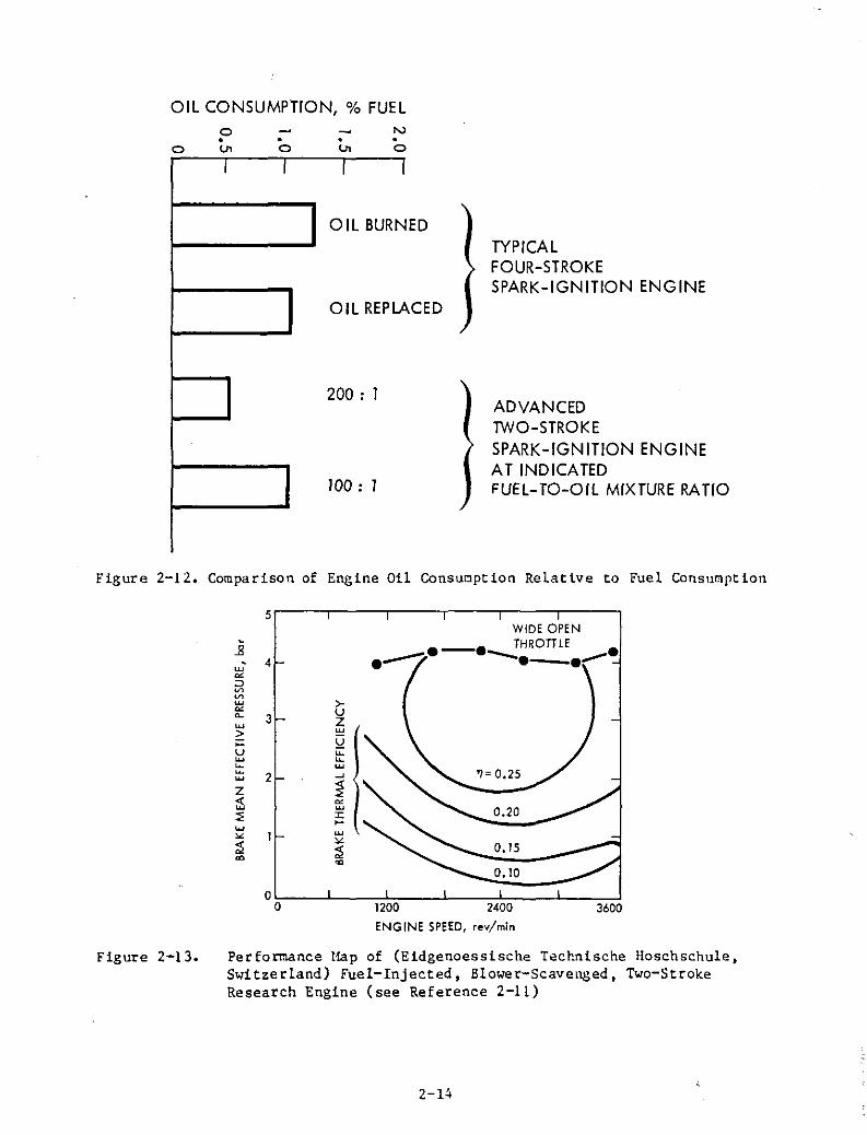
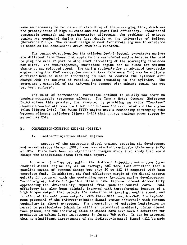
Similar results were also obtained with a cylinder fuel-injected, twostroke engine in Switzerland (References 2-11 and 2-12). The Swiss engine usesa production Motosacoche snowmobile engine modified for fuel injection andequipped with a separate blower instead of the piston to scavenge the engine.This modification makes it possible to lubricate the engine in a conventionalmanner and to improve the emission quality of the two-stroke engine, which,however, does not seem to be necessary. The lube oil consumption achievablewith a carefully metered two-stroke mixture lubrication system (Figure 2-12)is already as good as or better than that of a conventional four-stroke lubrication system. A definite advantage of a blower-scavenged engine, however, isits charge characteristics. As can be seen in Figure 2-13, because of thesquare pressure-speed relationship of the blower, the blower-scavenged engineproduces an amazingly flat torque output over all its speed range. If variablein speed, the blower could be used to control the engine by controlling thescavenging ratio. On the other hand, the required blower, drive mechanism,and required external ducting contribute to unwanted bulk and significantlyimpair the inherent simplicity of the two-stroke engine.
The pacing problems with the cylinder fuel-injected, two-stroke engineare that of high-speed fuel injection and system reliability. The pulse frequency of two-stroke fuel injection systems is twice as high as that neededfor four-stroke engines while the total fuel-injected per unit time is thesame. For research purposes Swiss researchers have used a conventional fourstroke, jerk-pump system running (as with four-stroke engines) at one-halfthe crankshaft speed with two plungers working alternately on one cylinder.The Japanese (see Reference 2-8) have modified a conventional Bosch fourstroke injection pump to work at two-stroke crankshaft speed, which is possible under laboratory conditions for a limited time. Efforts to solve thehigh-speed, fuel-injection problem for two-stroke and for diesel engines areunderway (see subsection II-D).
The inherent physics of the two-stroke engine is sensi t ive to dynamicinteractions between the engine cylinder cavity and the external flow systems,the inlet, and the exhaust. The possibility of scavenging a two-stroke enginewith resonance effects alone was demonstrated by Cadinnacy more than 50 yearsago. Since then the exhaust system of conventional carbureted two-strokeengines have been primarily tuned to boost low end torque and to improve midrange fuel economy by plugging the exhaust port with the returning pressure
2-9
HC EMISSIONS, ppm
<? 0-~ ~
BREAK MEAN- BREAK MEAN-EFFECTIVE PRESSURE, kg/em2
EFFECTIVE PRESSURE, kg/em2
0 N W .... '" 0- " 0 N W .... '" 0- "0 0
0>00m m
Z N Z NG'l 0
G'l 0
Z Zm ~ m
'" 0'" ~." ."m
0- m am m,0 W 8 0 .0 m
0 ."W 00~ m ~ ."m
Z m mZ Z Z3 3 ....5· 5· :I:x x '"00 .... .... =I0 00 0 0
N r-N m
CO EMISSIONS, %
BREAK MEANEFFECTIVE PRESSURE, kg/em
2
-"/ -.....~
~\\\
~6m
0 0;", ."
mZ....:I:'"
~0=lr-m
~
o
No
....o
'"o
mZG'lZm
N'"I .".... m
0 m,0~
m
Z35·x
00
N
BRAKE-SPECIFIC FUELCONSUMPTION, g/kWh
Figure 2-5. Maps Generated from Active Thermal Atmospheric CombustionTwo-Stroke Research Engine (see Reference 2-7)
FRONT VIEW SIDE VIEW
LEGEND:
WHITE: 1.2-1 THREE-CYLINDER, TWO-STROKE ENGINE
BLACK: 1.6-1 FOUR-CYLINDER, FOUR"STROKE ENGINE
Figure 2-6. Size Comparison of TWo- and Four-Stroke, Fuel-InjectedEngines of Comparable Performance (see Reference 2-9)
.Zo>=0-
~V>
Zou-'~
:::>~
uu:U~
0V>,~
'"~'"
~nt..::J
1.2-1, TWO-STROKESPARK-IGNITION ENGINE(ORBITAL ENGINE CO.)
1.6-1, FOUR-STROKESPARK-IGNITION ENGINE(GENERAL MOTORS)
1.5-1, FOUR-STROKESPARK-IGNITION ENGINE(FORD)
1.5-1, INDIRECT-INJECTIONDIESEL(VO LKSWAGEN)
Figure 2-7. Comparison of 25% Partload Brake-Specific FuelConsumption at 2000 rev/min (Reference 2-9)
2-11
100
800
1\ \600 I. \
~ \\ "-'" \ \ ......-as \~ --u' 400 •u.. ~. ----V> _.-'"
200
oL---l...._--l.__.J.-_--l._
a 25 50 75
LEGEND:
-- CARBURATED BASELINETWO-STROKE
--- FUEL-INJECTED TWO-STROKERESEARCH (ORBITAL ENGINE CO.)
---1.5-1, FOUR-STROKE (FORD)
----1.6-.P, (GM WORLD CAR CO.)FOUR-STROKE
PART LOAD, %
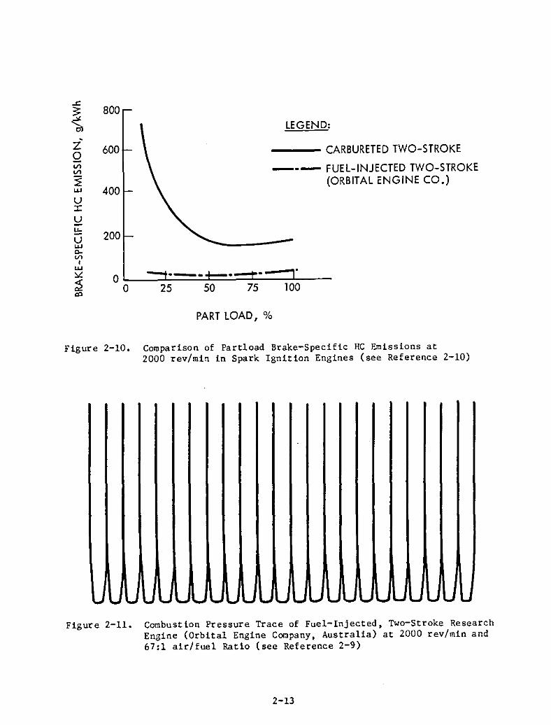
Figure 2-8. Comparison of Engine Partload Brake-Speciic Fuel Consumptionsin Spark-Ignition Engines (see Reference 2-10)
'"w 0Owwz"" .....::::iO~>-"'-,u:;;z, ,",,,,,
w
""o
He EMISSIONSNOX
EMISSIONS
- ..... ... "i' '" :::>:::>-'v>, 0 ..... OO:J0 '" ~ v>
0 u.. u.. u..
1: - - 0- r- - 1: ----,... , ...
0 ... ,... ~": , ,- - ": "l
r- - - r-r- -
-
Figure 2-9. Comparison of 25% Partload Brake-Specific Exhaust Emissionsin Spark-Ignition Engines at 2000 rev/min (see Reference 2-9)
2-12
800
0l......-_....c.:=:..=..:J==~_---l_-
o 25 50 75 100
LEGEND:
___ CARBURETED TWO-STROKE
--- FUEL-INJECTED TWO-STROKE(ORBITAL ENGINE CO.)
200
400
600-z
QV'lV'l
::EuJ
UJ:
~!:!:UuJc..Vl
IuJ~
;2'"
PART LOAD, %
Figure 2-10. Comparison of Partload Brake-Specific HG Emissions at2000 rev/min in Spark Ignition Engines (see Reference 2-10)
Figure 2-11. Combustion Pressure Trace of Fuel-Injected, Two-Stroke ResearchEngine (Orbital Engine Gocpany, Australia) at 2000 rev/min and67:1 air/fuel Ratio (see Reference 2-9)
2-13
OIL CONSUMPTION, % FUEL
oo•lJ1
•o.lJ1
.o
ADVANCEDTWO-STROKESPARK-IGNITION ENGINEAT INDICATEDFUEL- TO-OIL MIXTURE RATIO
TYPICALFOUR-STROKESPARK-IGNITION ENGINE
ED
LACED
I I I I
OIL BURN
OIL REP
200 : 1
100 : 1
Figure 2-12. Comparison of Engine Oil Consucption Relative to Fuel Consucption
5,------,-----,----r----,---,------,
.B• 4
w
'"::>~
~
w
'"~ 3w>;::uw~
::; 2Z~::;
WIDE OPENe-e THROTTLE ee~ -e_.-
0.20
0.15
0.10
o~---l...-____;~--.l.--_;;_;';;:;;----l...-__:_:_=o 1200 2400 3600
ENGINE SPEED, rev/min
Figure 2-13. Perforcance Hap of (Eidgenoessische Technische lIoschschule,Switzerland) Fuel-Injected, Blower-Scavel~ed, Two-StrokeResearch Engine (see Reference 2-11)
2-14
,'/i,
wave as necessary to reduce short-circuiting of the scavenging flow, which wasthe primry cause of high HC emissions and power fuel efficiency. Broad-basedsystematic research and experimentation addressing the problems of exhausttuning was conducted during the last decade at the University of Belfast(Reference 2-13). The exhaust design of most two-stroke engines in existenceis based on the conclusions drawn from this research.
The tuning objectives for the cylinder fuel-injected, two-stroke enginesare different from those that apply to the carbureted engine because the needto plug the exhaust port to stop short-circuiting of the scavenging flow doesnot exist. The fuel-injected, two-stroke engine can be tuned for maximumcharge at any selected speed. The tuning rationale for an advanced two-strokeengine using the ATAC combustion concept (see Reference 2-8) may be entirelydifferent because exhaust throttling is used to control the cylinder aircharge with the amounts of residual gases remaining in the cylinder. Theimprovement potential of the ATAC-engine concept with exhaust tuning has notyet been explored.
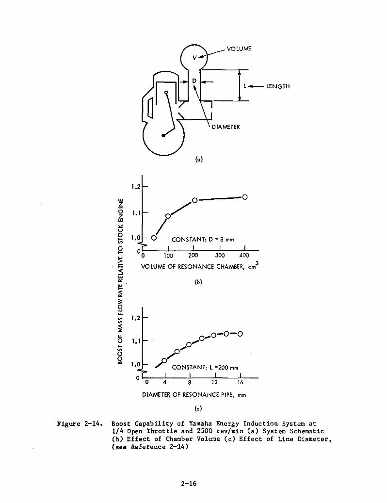
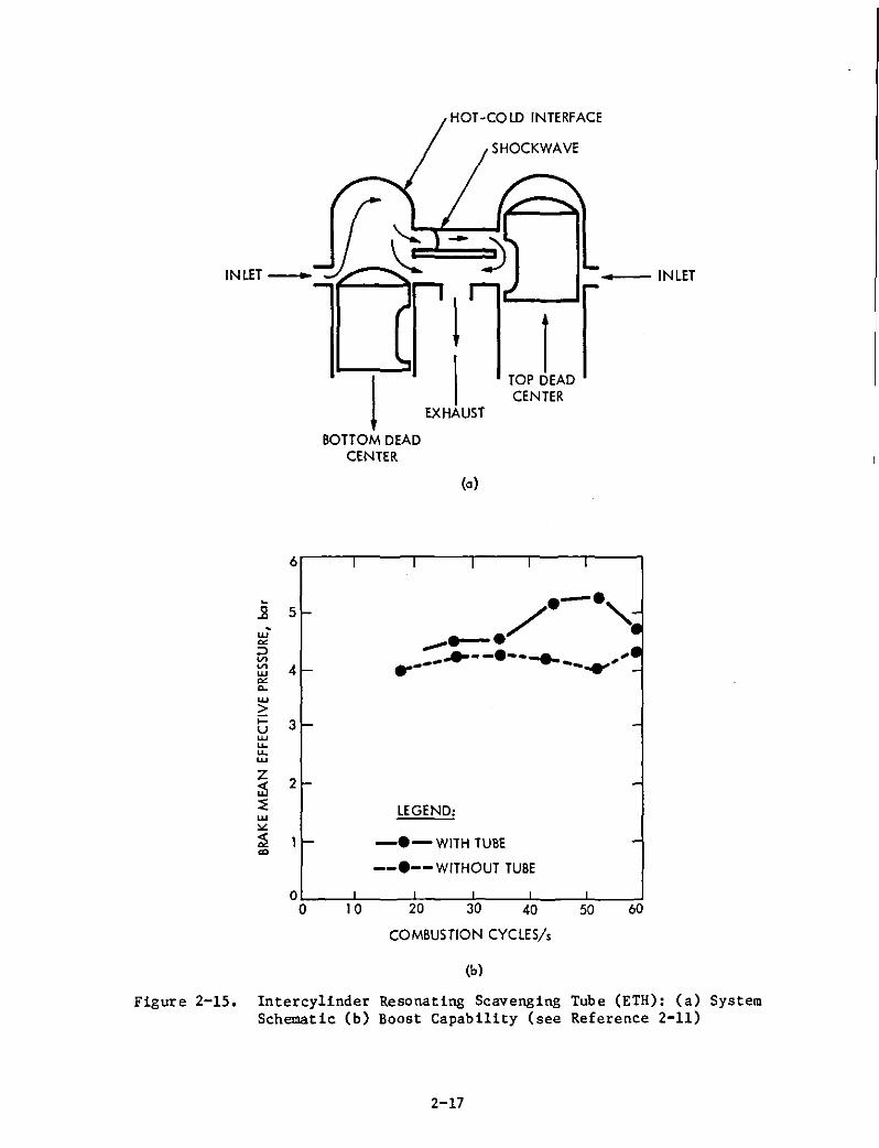
The inlet of conventional two-stroke engines is usually too short toproduce noticeable resonance effects. The Yamaha Motor Company (Reference2-14) solves this problem, for example, by providing an extra "Ton-Raum"chamber branched off from the inlet duct between the carburetor and the engineinlet (Figure 2-14). The Swiss (ETR) engine uses a resonating scavenging tubebetween adjacent cylinders (Figure 2-15) that boosts caximum power torque byas much as 25%.
B. COMPRESSION-IGNITION ENGINES (DIESEL)
1. Indirect-Injection Diesel Engines
Aspects of the automotive diesel engine, covering the developmentand market status through 1981, have been studied preViously (Reference 2-15)at JPL. There have been no significant changes since that study that wouldchange the conclusions drawn from this report.
In terms of miles per gallon the indirect-injection automotive (prechamber) diesel engine is, as an average, 40% more fuel-efficient than agasoline engine of current design but only 20 to 25% if compared with basepetroleum fuel. In addition, the fuel efficiency margin of the diesel narrowsquickly·l£ compared with the contending spark-ignition engine developments.Turbocharging, indirect-injection diesels have improved diesel driveabUityapproaching the driveabUity expected from gasoline-powered cars. Fuelefficiency has also been slightly improved with turbocharging because of ahigh torque output that permits the reduction of gearing, engine speed, andfriction at the same power output. With these measures, however, the improvement potential of the indirect-injecion diesel engine achievable with currenttechnology is almost exhausted. The uncertainty of emission legislation inregard to particulates (which is still an unresolved problem), rising dieselfuel prices, and the declining sales of·diesel cars have been a deterrent forproducers in making large investments in future R&D work. It can be expectedthat no significant improvements of the indirect-injected diesel will be made
2-15
VOLUME
16128
1.2
/0 0wZC> 1.1Z 0w
I>tU0 1.0 CONSTANT: D = 8 mm...V>
000...
100 200 300 400~;:: VOLUME OF RESONANCE CHAMBER, em
3
:5w
'" (b)w...~~
9...V> 1.2V>
~ 0-0-0...0 1.1 0'"... 0"V> 0""0 ,/0
,/J CONSTANT: L =200 mm'" 1.0
DIAMETER OF RESONAI"CE PIPE, mm
(e)
Figure 2-14. Boost Capability of Yamaha Energy Induction System at1/4 Open Throttle and 2500 rev/min (a) System Schematic(b) Effect of Chamber Volume (c) Effect of Line Diameter.(see Reference 2-"14)
2-16
1BOTTOM DEAD
CENTER
HOT-CO LD INTERFACE
SHOCKWAVE
.. INLET
1TOP DEADCENTER
(0)
6...---r---.,--..,----r---r-----.
.w
""::>VIVIW
""0-
W
>i=uwu..u..w
5
4
3
2
e-e,_e-e/~--.--..... '...-_.. --.......'
LEGEND:
-e-WITH TUBE
--e--WITHOUT TUBE
O'--_--L__--L__--,L,__--'-__.1-_--'o 10 20 30 40 50 60
COMBUSTION CYCLES/,
(b)
Figure 2-15. Intercy1inder Resonating Scavenging Tube (ETH): (a) SystemSchematic (b) Boost Capability (see Reference 2-11)
2-17
within the projected ten-year· time frame that will alter the conclusionsdrawn at this time.
2. Direct-Injection Diesel Engines
A still untapped potential for the improvement of the small. highspeed diesel is that of direct-fuel injection. which would improve its poweroutput and fuel economy by approximately 15%. This will be necessary tomaintain the lead against gasoline engine contenders of advanced design. Thepacing problems are those of short-injection times. waterhammer line effects.and diesel knock due to ignition delay. In a joint R&D effort between theBavarian Motor Works (BMW) and Austro-Steyer (Reference 2-16). the basicfeasibility of a direct-injection diesel for passenger cars was demonstratedat BMW/Steyer with a design approach that provides for single-plunger injection pumps for each individual cylinder and for an accoustically attenuatingengine structure. Because of the uncertain future of diesel powered passengercars and technical difficulties encountered. this engine project was discontinued.
Efforts to improve the direct-injection diesel engine by turbocompounding and the introduction of ceramic materials are being done under u. S.Government contract at Cummins. However. these efforts cannot be expectedto have a bearing on the design of passenger-car-sIze diesels within theprojected (ten-year) time frame.
All of the R&D work on automotive diesels is exclusively oriented towardthe four-stroke engine. Two-stroke. direct-injection diesels are successfullyused to power trucks. railroad locomotives. and ships. There is no noticeableR&D work in progress to use the potential of the two-stroke diesel for automotive applications. As in the case of the small four-stroke diesel engines.fuel injection is the pacing problem with two-stroke. direct-injection dieselengines.
C. EXTERNAL COMBUSTION ENGINES
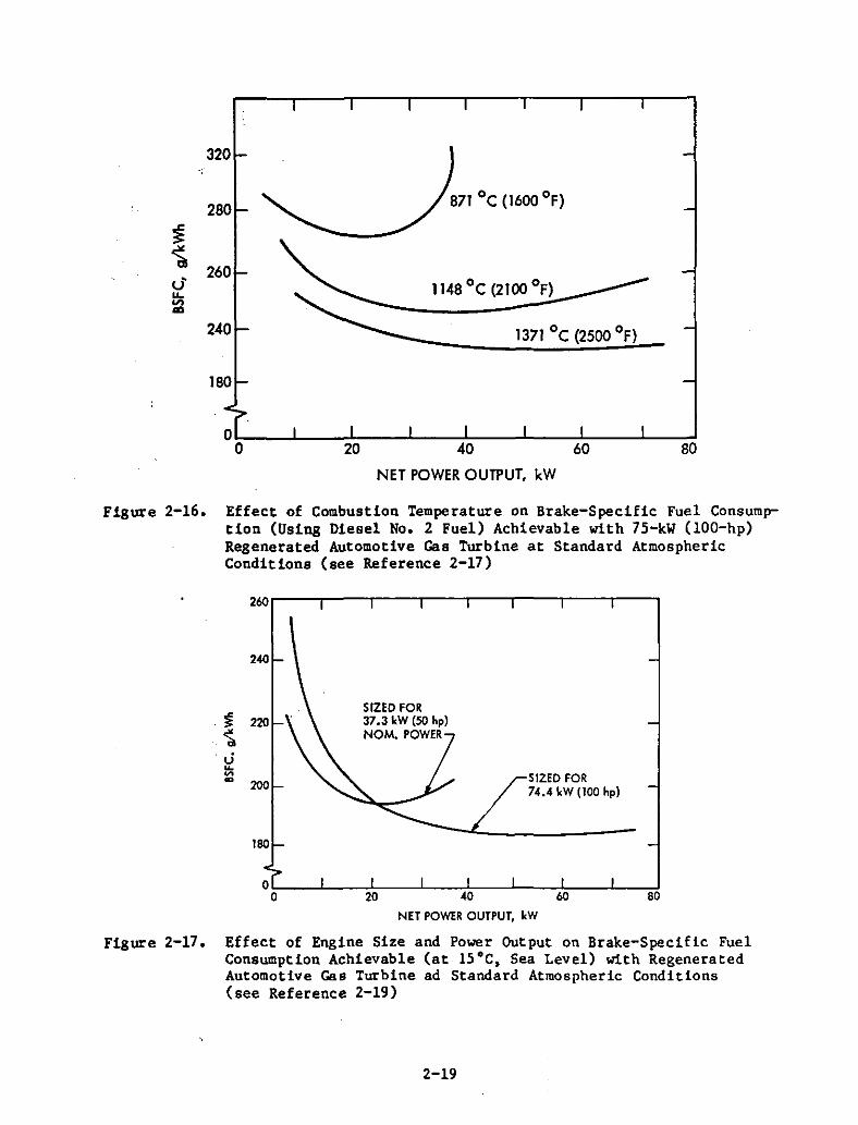
1. Brayton Engines (Gas Turbine)
The development of automotive gas turbines has made significantprogress during the last decade in regard to component efficiency. low NOxcombustion. and the development of a usable regenerator. The inherent problems inhibiting automotive application are those of an inherently poorpart-load fuel efficiency and the high operating temperatures needed to produce a competitive fuel efficiency over a wide speed and power range.
While part-load fuel efficiency can be improved to a certain extent withvariable geometry. high operating temperatures from 1300 to l400·C (2300 to2500·F) are needed to achieve canpet1tive fuel efficiency (Figure 2-16.Reference 2-17). The compatibility of the hot-path components with thesetemperatures requires the introduction of ceramic materials. The strengthof structural ceramics at high temperatures has be'i'n significantly improvedduring the last 10 years. but their brittleness and notch sensitivity still
2-18
8020 40 60
NET POWER OUTPUT, kW
871°C (1600 of)
320
280
$~
260u'....'"<D
240
180
00
Figure 2-16. Effect of Combustion Temperature on Brake-Specific Fuel Consumption (Using Diesel No. 2 Fuel) Achievable with 7S-kW (lOO-hp)Regenerated Automotive Gas Turbine at Standard AtmosphericConditions (see Reference 2-17)
260 '---"'T""---,.---r--"'T""---r---,---r----,
240
180
SIZED FOR37.3 kW (SO hpJNOM. POWER
SIZED FOR74.4 kW (100 hpJ
oI:--....L.--:';,------'---+.----!----;l::---..l--,,,,!o 20 40 60 80
NET POWER OUTPUT, kW
Figure 2-17. Effect of Engine Size and Power Output on Brake-Specific FuelConsumption Achievable (at ISoC. Sea Level) with RegeneratedAutomotive Gas Turbine ad Standard Atmospheric Conditions(see Reference 2-19)
2-19
represent a major design probletl, especially lolhen frequent temperature changesare encountered. Differential thermal expansions of the materials make thedesign of unavoidable metallic-ceramic interfaces and joints problematic.
A problem also for the automotive Brayton engine is size (Figure 2-17,Reference 2-18). The efficiency of Brayton engine compressors and turbinesdeteriorate significantly with diminishing size due to (1) Reynolds numbereffects, (2) increased turbine and' compressor clearance losses, (3) pooraerodynamic quality of the blading, and (4) increased leakage across theregenerator hot-cold interfaces., Unfortunately, a higher operating temperature leads also to a smaller engine for a given power output. This 1n turnoffsets some of the thermodynamic efficiency gains achievable with a higheroperating temperature. /
/State-of-the-art automotive gas turbines are the GT 100, under develop-
ment at the Detroit Diesel Allison (DDA) Division of General Motors (Reference2-19) and the GT 101 >see Reference 2-17), under development at the GarrettAiResearch Corporation. According to specifications of the United StatesDepartment of Energy~ both turbines are designed to develop a maximum power of75 kW (100 hp) at the driveshaft, lolhich is considered the minimum power outputproducible without intolerable, small-size penalties. Using a rotary heatexchanger, bot';lengines are basically of the same thermodynamic concept, butentirely different design approaches are taken to comply with the 100-hp
/requirement./ With an all-concentric design and a single-shaft radial turbine,AiResearch 1s aiming at an optimum achievable minimum overall size andinterior aerodynamic cleanliness and symmetry. With a conventionally angledoff combustion chamber feeding into a convolute and separate axial powerturbine, the DDA design is more conservative and compromising for the benefitof development flexibility.
Despite optimistic projections that predicted the market penetration ofautomotive Brayton engines to start in 1985, it will probably take 10 to 15years for the automotive Brayton engine to mature into a production engine.As in the case of the diesel engine, it also becomes difficult for the Braytonengine to compete with the development of advanced versions of potentialcandidate engines.
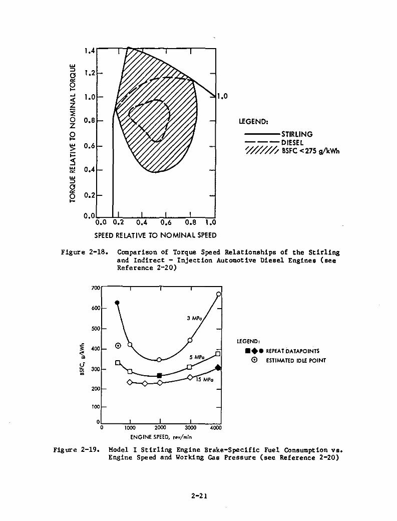
2. Stirling Engines
Theoretically, the Stirling engine is the most efficient heatengine concept. As shown in Figures 2-18 and 2-19, fuel efficiencies equivalent to and better than that of an indirect injection-diesel over a wideoperating range have already been demonstrated with a state-of-the-artautomotive Stirling engine jointly designed and developed by MechanicalTechnology, Inc, and United Stirling in Sweden (Reference 2-20).
Unfortunately, the Stirling concept has twO inherent problems thatinhibit its development into a competitive automotive engine. Changing thepower output requires a change of the mass of the working fluid that participates in the heat cycle. For an increase in power, more mass of working fluidmust be bled into the system from a high-pressure source. The other inherentproblem 1s that of sealing. To size a Stirling engine down into a package
2-20
1.2
1.0
w=>~8....~~o 0.8Z
8~ 0.6i=:s~ 0.4w=>~8 0.2
LEGEND:
---STIRLING---DIESEL~////// 8SFC <275 e/kWh
O.OL-....LL--_L--_..l..-_...l.-_...,J0.0 0.2 0.4 0.6 0.8 1.0
SPEED RELATIVE TO NOMINAL SPEED
Figure 2-18. Compariaon of Torque Speed Relationships of the Stirlingand Indirect - Injection Automotive Diesel Engines (seeReference 2-20)
LEGEND,
••• REPEAT DATAPOINTS
o ESTIMATED IDLE POINT
700
600
SOO
~ 400~u·
300...~m
200
100
00 1000 2000 3000 4000
ENGINE SPEED, rev/min
Figure 2-19. Model I Stirling Engine Brake-Specific Fuel Consumption vs.Engine Speed and Working Gas Pressure (see Reference 2-20)
2-21
that is acceptable for the designer of an automobile, hydrogen must be used asa working fluid, and high operating pressures of about 15 MPa (2175 psi) mustbe applied. The combination of both of these necessities imposes seal ingproblems that to date have not been satisfactorily resolved. As in the caseof the Brayton engine, it is uncertain when the Stirling engine will matureinto an automotive engine within the projected (la-year) time period.
3. Rankine Engines (Steam Engine)
The efficient use of the Rankine process requires deep expansioninto the vacuum generated by a condenser, which is impractical for a passenger-car engine. For piston eKpanders the inherent problem is that of deadvolume. To overcome this problem, the Carter automotive steam engine (Reference 2-21) uses high pressures of about 17 MPa (2500 psi) and a pistonactivated poppet valve in the cylinder head, which is a concept of questionable integrity if used at high engine speeds. A variety of eKpander conceptshave been conceived and tested but have not succeeded in producing sufficiently deep e><pansion without unwanted complexity and bulk.
To achieve fuel efficiencies that only appro~imate those of conventionalspark-ignition engines, the carter engine also applied superheating to temperatures up to 540·C (lOOO·F). These high temperatures impose cylinder lubrication problems that have not been resolved. Lear had the same problems withhis automotive steam-engine project. Because the automotive steam-Rankineengine offers no potential for competition with current automotive designs,government supported R&D was discontinued several years ago.
D. FUEL-INJECTION SYSTEMS
Four-stroke, spark-ignition engines of state-of-the-art design areusually equipped with a single- or multi-source, continuous-flow, fuelinjection system. The fuel flow is primarily controlled by an air-flow meterin conjunction with an oxygen probe positioned in the exhaust. Engines thatdepend on a cyclic injection of fuel into the cylinder are (1) diesels; (2)advanced, two-stroke, spark-ignition engines; and (3) programmed combustion(Ford-PROCO), four-stroke, spark-ignition engines.
For small automotive engines, the pacing problems with cyclic cylinderfuel injection are (1) the short time available for injection, (2) the smallamount of fuel to be injected per cycle, and (3) the achievement of a goodfuel atomization over a wide range of engine speeds and fuel flow rates. Thehigh-speed, fuel-injection problem becomes especially pronounced in two-strokeengines because the number of pulses to be delivered per unit time is twiceas high, whereas the time available for injection and the amounts of fuel tobe injected per cycle are only one half that of a four-stroke engine.
The research with two-stroke engines in Japan and Switzerland (seeReferences 2-8 and 2-11), featured modified production, four-stroke, fuelinjection systems of the Bosch jerk-pump type. These were adequate for laboratory tests but were limited in the time engines could be operated at full powerand speed. Both of the indicated researchers agree that new solutions to thetwo-stroke, fuel-injection problem must be found.
2-22
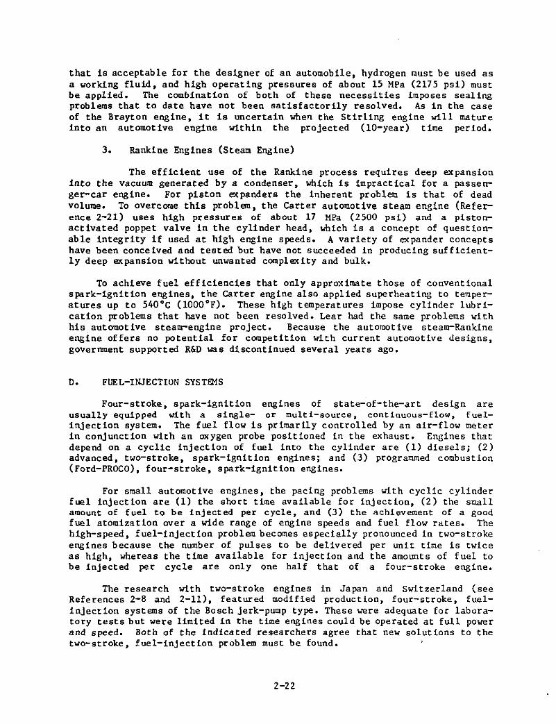
Reportedly (see Reference 2-12), the Federal Swiss Institute of Technology (ETH) is developing an electronically controlled cylinder, fuelinjection system applicable to diesels and spark-ignition engines that iscapable of producing the typical programmed injections at high speeds (Figure2-20). The system is said to be capable of producing 100+ pulses per secondat pressures up to 600 atm. The system is an ETH .proprietary item that hasnot been published.
The Australian researchers have taken an approach to the high-speed,fuel-injection problems of their own (described in detail in Reference 2-10).As shown in Figure 2-21, the concept uses a combination of compressed air andplunger-displacement metering to inject an extemely rich fuel-air mixture intothe cylinder. This system has been successfully used in the OEC-research,two-stroke engine described in subsection A-3. It produced an extremely widerange of total air-to-fuel ratios so that partload could be controlled bymeans of air-to-fuel variation alone without throttling the engine.
According to press publications such as WARDS Engine Update and Automotive News, several prominent producers of fuel-injection systems such asBosch and Lucas are making progress in the development of electronicallycontrolled, cylinder fuel-injection systems for high-speed diesels. It can,therefore, be reasonably assumed that the fuel-injection problems of the twostroke engine can be resolved in the future.
E. FREE-PISTON ENGINES
Because force actions are primarily of an inertial, dynamic nature,free-piston engines have a particularly attractive potential for diesels andfor alcohol-fueled, spark-ignition, combustion cycles. There is no crankshaft,and high compression ratios can be produced without combustion-preosurerelated friction penalties. Figure 2-22 compares the predicted frictionlosses and the power output of a resonating free-piston diesel engine againstdata obtained with a conventional two-stroke crankshaft diesel. As can beseen, the free-piston friction losses are nearly constant whereas the frictionlosses of the crankshaft engine rise steeply with speed by a factor of morethan six. This translates into a power and fuel efficiency gain of up to 40%.The problem is how to efficiently extract the power generated by a free-pistonengine.
Uniflow-scavenged, two-stroke, diesel free-piston engines of the opposedpiston type were first developed by Junkers in Germany and Pescara in Francebetween 1930 and 1950. Because of their compactness, narrow width, and smoothvibration-free operation, diesel free-piston compressors were for many yearsthe preferred source of energy to power jackhammers on construction sites andto pressurize torpedo systems on submarines. Pescara experimentally used twoor more free-piston diesel compressors in parallel as ·a gasifier for gasturbines to power trucks and ships. The Pescara free-piston engine (Figure2-23, Reference 2-22) had a power output of 90 kW at 1800 cycles per minuteand (including power turbine and gears) a weight of 278 kg!kW, which is lightfor a diesel engine. However, including the turbine and reduction gears, thePescara power system was not competitive with diesels of conventional crank-
2-23
(a)
LEGEND:
1 - FUEL PUMP2 - PRESSURE CONTROL VALVE3 - ORIFICES4 - SOLENOID VALVE5 - DIFFERENTIAL PISTON6 - PINTlE7 - COMBUSTION CHAMBER
I!:!~3:
(b) 9.u-...!.w:JU-
CRANK ANGLE
Figure 2-20. Swiss Institute of Technology Fuel-Injection System (a) SystemSchematic (b) Typical Fuel-Injection Pattern CharacteristicsProducible with the System (see Reference 2-12)
2-24
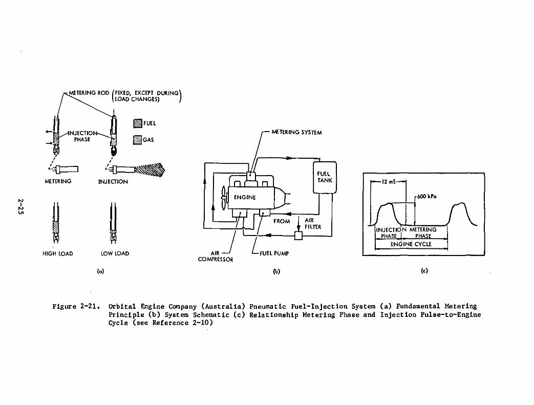
600 kPa
ENGINE CYCLE
INJECTION METERINGPHASE PH S
FUElTANK
AIRFIlTER
ENGINE
COMPRESSOR
~FUEl
ID1I!GAS
,
.'_~~INJECTION
lOW LOAD
METERING ROD (FIXED, EXCEPT DURING)LOAD CHANGES)
INJECTIOPHASE
J,l:{l:::::l
.....
METERING
-
HIGH lOAD
(a) (b) (e)
Figure 2-21. Orbital Engine Company (Australia) Pneumatic Fuel-Injection System (a) Fundamental MeteringPrinciple (b) System Schematic (c) Relationship Metering Phase and Injection Pulse-to-EngineCycle (see Reference 2-10)
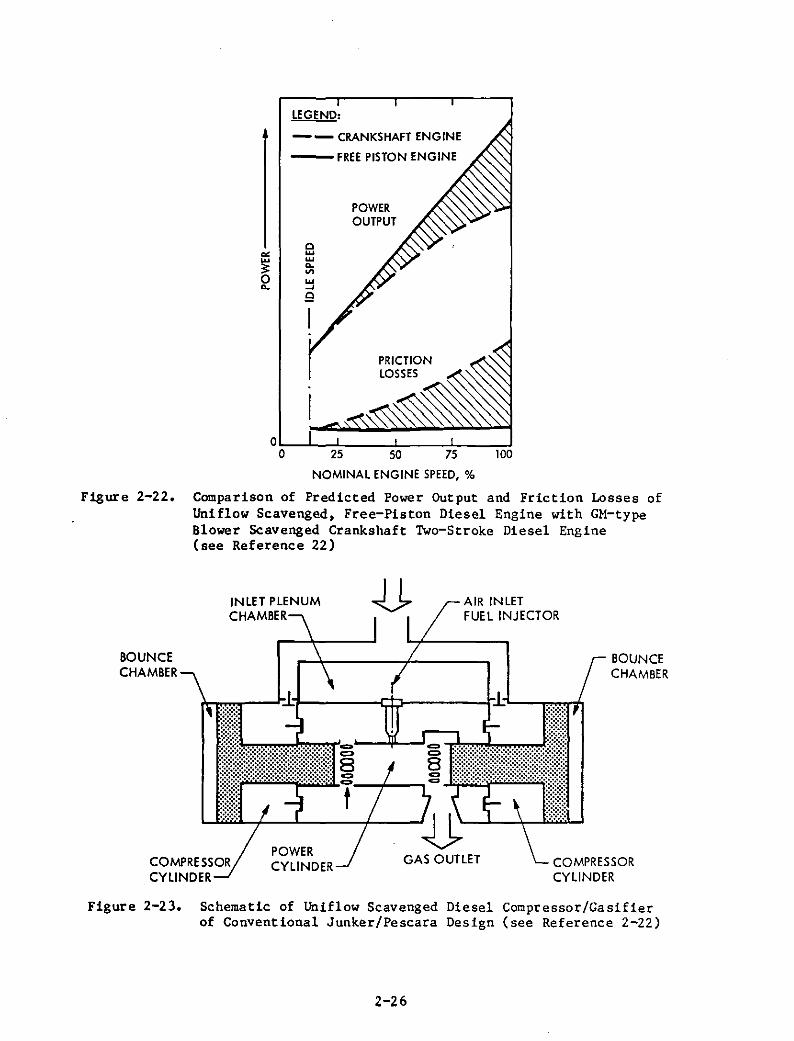
PRICTIONLOSSES
POWEROUTPUT
oww....'"~Q
""~o....
LEGEND:
-- CRANKSHAFT ENGINE
---FREE PISTON ENGINE
oI,-....L.---Jl-----l---,L_--:.."Jo 25 50 75 100
NOMINAL ENGINE SPEED, %
Figure 2-22. Comparison of Predicted Power Output and Friction Losses ofUniflow Scavenged, Free-Piston Diesel Engine with GM-typeBlower Scavenged Crankshaft Two-Stroke Diesel Engine(see Reference 22)
BOUNCECHAMBER
COMPRESSORCYLINDER
AIR INLETFUEL INJECTOR
GAS OUTLETPOWERCYLINDER
INLET PLENUMCHAMBER
COMPRESSORCYLINDER
BOUNCECHAMBER
Figure 2-23. Schematic of Uniflow Scavenged Diesel Compressor/Gasifierof Conventional Junker/Pescara Design (see Reference 2-22)
2-26
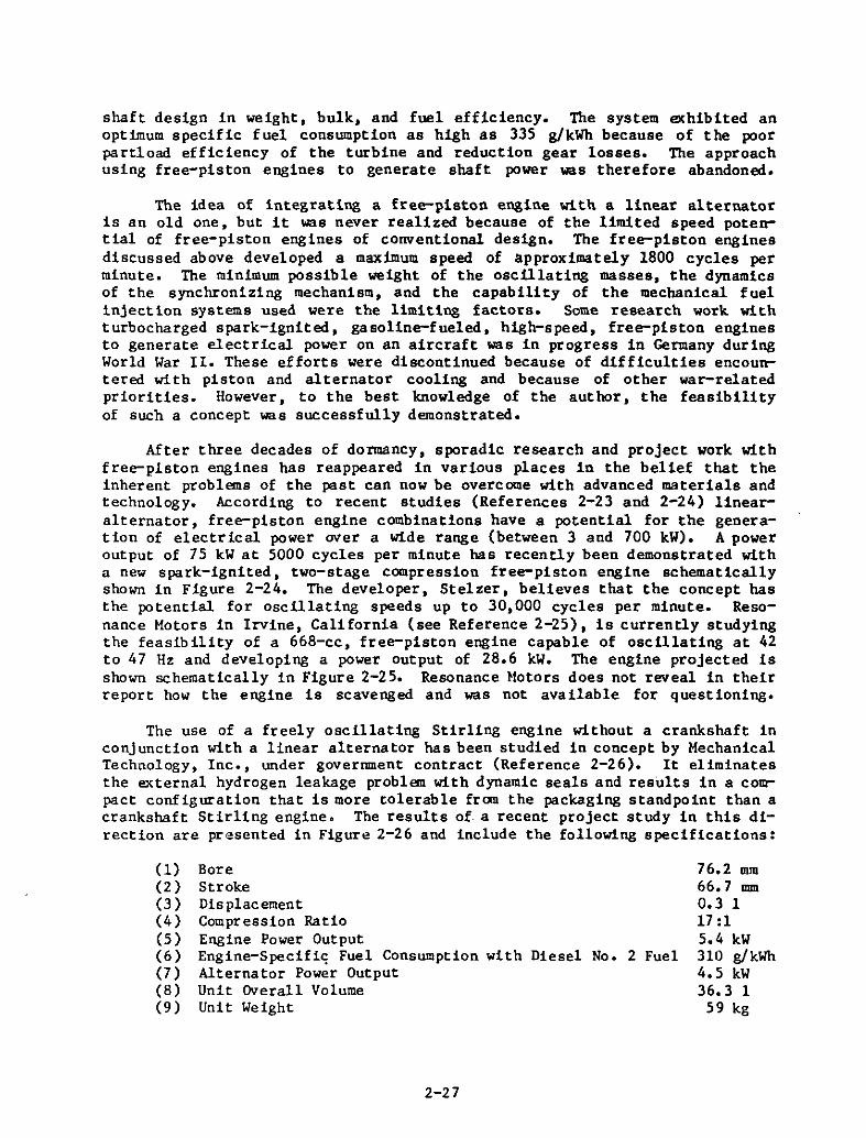
shaft design in weight, bulk, and fuel efficiency. The system exhibited anoptimum specific fuel consumption as high as 335 g/kWh because of the poorpartload efficiency of the turbine and reduction gear losses. The approachusing free-piston engines to generate shaft power was therefore abandoned.
The idea of integrating a free-piston engine with a linear alternatoris an old one, but it was never realized because of the limited speed potential of free-piston engines of conventional design. The free-piston enginesdiscussed above developed a maximum speed of approximately 1800 cycles perminute. The minimum possible weight of the oscUlating masses, the dynamicsof the synchronizing mechanism, and the capability of the mechanical fuelinjection systems used were the limiting factors. Some research work withturbocharged spark-ignited, gasoline-fueled, high-speed, free-piston enginesto generate electrical power on an aircraft was in progress in Germany duringWorld War II. These efforts were discontinued because of difficulties encountered with piston and alternator cooling and because of other war-relatedpriorities. However, to the best knowledge of the author, the feasibilityof such a concept was successfully demonstrated.
After three decades of dormancy, sporadic research and project work withfree-pIston engines has reappeared in various places in the belief that theinherent problems of the past can now be overcome with advanced materials andtechnology. According to recent studies (References 2-23 and 2-24) linearalternator, free-piston engine combinations have a potential for the generation of electrical power over a wide range (between 3 and 700 kW). A poweroutput of 75 kW at 5000 cycles per minute has recently been demonstrated witha new spark-ignited, two-stage compression free-piston engine schematicallyshown in Figure 2-24. The developer, Stelzer, believes that the concept hasthe potential for oscUlating speeds up to 30,000 cycles per minute. Resonance Motors in Irvine, California (see Reference 2-25), is currently studyingthe feasib ility of a 668-cc, free-piston engine capable of oscUlating at 42to 47 Hz and developing a power output of 28.6 kW. The engine projected isshown schematically in Figure 2-25. Resonance Motors does not reveal in theirreport how the engine is scavenged and was not available for questioning.
The use of a freely oscUlating Stirling engine without a crankshaft inconjunction with a linear alternator has been studied in concept by MechanicalTechnology, Inc., under government contract (Reference 2-26). It eliminatesthe external hydrogen leakage problem with dynamic seals and results in a compact configuration that is more tolerable from the packaging standpoint than acrankshaft Stirling engine. The results of· a recent project study in this direction are presented in Figure 2-26 and include the following specifications:
(1) Bore(2) Stroke(3 ) Dis plac ement(4) Compression Ratio(5) Engine Power Output(6) Engine-Specifi~ Fuel Consumption with Diesel No.2 Fuel(7) Alternator Power Output(8) Unit Overall Volume(9) Unit Weight
2-27
76.2 mm66.7 mm0.3 117:15.4 kW310 g/kWh4.5 kW36.3 1
59 kg
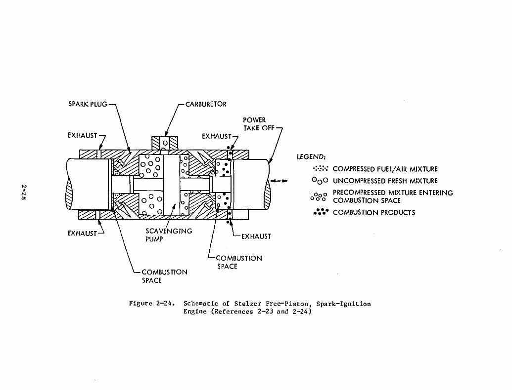
NI
N(Xl
EXHAUST
EXHAUST
CARBURETOR
POWERTAKE OFF
LEGEND:
.:.:.:.: COMPRESSED FUEl/AIR MIXTURE
- 000 UNCOMPRESSED FRESH MIXTURE
'000 PRECOMPRESSED MIXTURE ENTERING000 COMBUSTION SPACE
•••••• COMBUSTION PRODUCTS
EXHAUST
COMBUSTIONSPACE
COMBUSTIONSPACE
Figure 2-24. Schematic of Stelzer Free-Piston, Spark-IgnitionEngine (References 2-23 and 2-24)
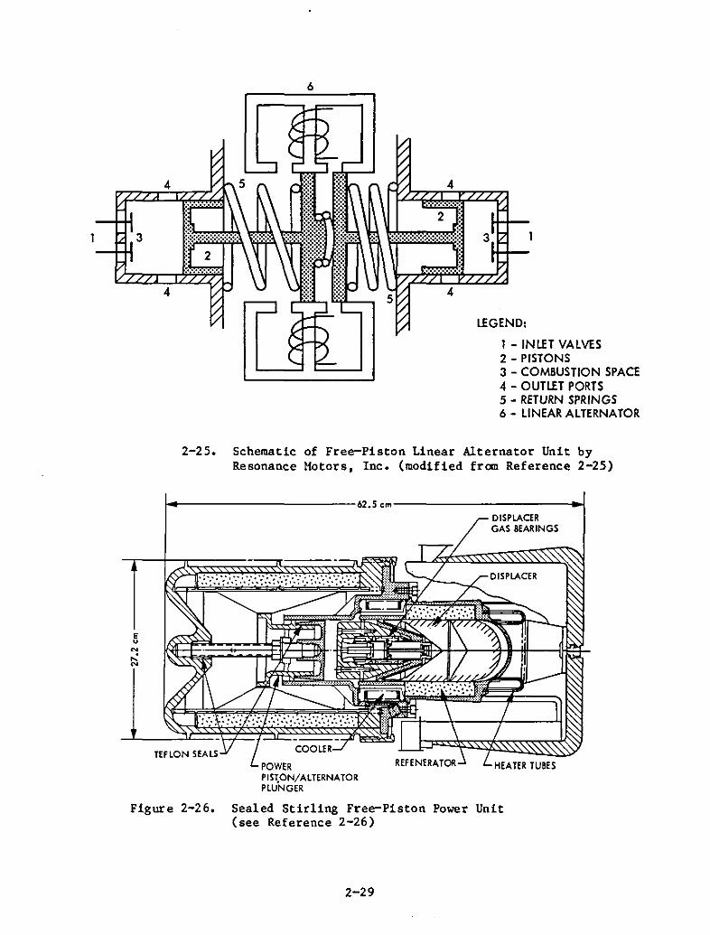
6
3
4
4
3
LEGEND:
1 - INLET VALVES2 - PISTONS3 - COMBUSTION SPACE4 - OUTLET PORTS5 - RETURN SPRINGS6 - LINEAR ALTERNATOR
2-25. Schematic of Free-Piston Linear Alternator Unit byResonance Motors, Inc. (modified from Reference 2-25)
j.-------------62.5cm-------------.jDISPLACERGAS 8EARINGS
HEATER TU8ES
DISPLACER
Eu
'"~
COOLER
POWERPIS,ON/ALTERNATORPLUNGER
Figure 2-26. Sealed Stirling Free-Piston Power Unit(see Reference 2-26)
2-29


SECTION III
POTENTIAL FOR HYBRID VEHICLE APPLICATION
Figure 3-1 generically compares the key properties of the engine concepts under consideration. These concepts are discussed in the followingsuhsections.
A. BRAYTON ENGINE
Fuel efficiencies that theoretically can be obtained with a regeneratedBrayton engine (see Figures 2-16 and 3-1a) are very competitive, provided theprojected component efficiencies and operating temperatures can be achievedwith production hardware. As shown in Figure 3-lb there are no striking sizeor packaging advantages of the Brayton engine over its piston-engine counterparts because of the bulkiness of the heat exchanger, associated ducts, drivemechanisms, and the housings required for gearing down from the turbine to theoutput power shaft.
Because of its multi-fuel capability, the Brayton engine would be theideal heat engine for a hybrid, but the gas turbine does not lend itself tohybrid operations that require rapid stop-start capability. It takes a minimumof 5 s to crank the compressor into the boot-strapping range and another 5 sor more to accelerate the rotor, gears, and the heat eJ<changer mass to fullmaximum speed. It also takes a certain time to achieve the hardware thermalequilibrium necessary to obtain good fuel efficiencies typical of a regenerated Brayton engine. Special precautions to obtain an acceptable stop-startcapabiity could be taken but still remain undeveloped. The compressor inlet,for example, could be shut off during cranking and opened instantly uponreaching boot-strapping speed to reduce compressor and turbine work and toprevent heat exchanger coolout. Low-inertia shutters that can be operatedquickly would probably be needed across the inlet and outlet plane of theheat exchanger to prevent undesirable heat losses during engine shutdowns.
The Brayton engine would have a potential for battery charging if scaledto the desired power output (20 to 30 kW). Because of small-size effectsthis would not be possible without strong fuel-efficiency penalties (seeFigure 2-17). A direct power take-off from the turbine rotor in the form ofelectrical energy would be the ideal way to charge the battery of a hybridvehicle. Assuming that a down-scaling at constant Mach-numbers without animpairment of the engine thermodynamics is possible in the future, withsingle-shaft Brayton engines of advanced design, for the power output ofinterest (20 to 50 kW), the shaft speeds would be in the order of 100,000 to165,000 rev/min.
Unfortunately, the low level of funding currently provided for the development of automotive gas turbines, as well as the dependence on ceramictechnology, makes it difficult to predict at what time an economical gas turbine might be commercially available. It seems probable that no mature Brayton
3-1
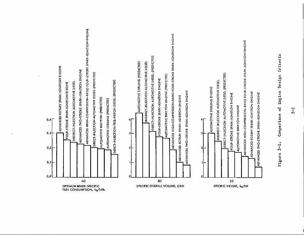
z_8
z zo
_. ,.2 v, _ _ _z - _ -z _. _ - D _ _- ._ _ e o D _ o0o_z _ °___" _v_ z _ o 8 _ z o ,_ _ _, _ oz o _ _ _ "-' '- > __- _ -, _ _. _ _ _ _ __" _ > O_.=__ _ _ o_o__ o _ _-_ _z_ °_ o 9 _, i _ - = v_ ,- _- _ _ z z _" - _- o - "_
z -° z z =ou_ o_ .o__.__z ">- z w-- _ _ _ o z z _ o__ _. _ _ _ ° _ _ 8 s Z o _ _ °
o ,z __ _
_uo___ _o ___-- 0 O -- --_
oo_o____ o_. I-I_;'-" __- _ °0.4 u _ _ O 41--
____ 8 _= o_OO,, _ a-_ _o__-- ,,,-IT
v "_ _ _ 8 ,,_ >. O _.. _
, u u -_ ._ _ __ . - _- _. w _o
°'3 r"_-_ -- z z z _ _, 8 S 8 i_ ° _ --
I I° e >_>_0 _ ± _ _ _ _ _zz ° > _-_°_= = o ._ o
o ,o%,,- ._-,_ o z >__, _ ,-,_ U _, O ,_
oa _ _ _, _- z _ _:
• ._ z __ ,-, ,-, _,
0.0 .
(a) ('o) (c)OPTIMUMBRAKE-SPECIFIC SPECIFICOVERALLVOLUME,J_/kW SPECIFICWEIGHT,kgikWFUELCONSUMPTION, kg/kWh
engine will be available within the 10-year time frame under considerationfor this study.
B. STIRLING ENGINE
Superior fuel efficiency, low NOx emissions, low noise level, and thecapabilty to adapt to a variety of alternative fuels are attractive featuresfor any application in which an inherent relatively slow response and bulkiness do not matter. Because packaging considerations are of primary importance in hybrid-vehicle design, the Stirling engine does not seem to be suitedfor a hybrid powertrain concept where most (two-thirds) of the power muststill be generated by the heat engine. The necessity of using hydrogen andrelatively high operating pressures (>2000 psi) as well as the hazard ofhydrogen leakage are of great concern in the use of a Stirling engine withinthe confines of a passenger car. In addition, it takes a minimum of 30 sfor a cold Stirling engine to develop full power, which precludes its use ina rapid stop-start manner.
A more practical use of the Stirling concept is as a sealed free-pistonengine linear-alternator unit to charge batteries (see Figure 2-26). Thisapplication would eliminate e<ternal leakage (the sealing problem with dynamicseals) and result in a better configuration for packaging. Approaches in thisdirection merit special attention although it is believed that they will haveno bearing on any hybrid development work that will take place within theprojected 10-year time frame.
C. DIESEL ENGINE
Compared with other candidate internal-combustion advanced engines(Figure 3-1), the indirect-injection diesel is less efficient in all categories, including that of fuel efficiency. If the problem of high-speed directinjection can be resolved, an improvement of about 15% over the indirectinjection engine would result. However, the diesel engine's inherently poorstart-up ability in cold weather (requiring preheating) and its high startingtorque and· motoring power requirements would still deter its use in s hybridvehicle. Idling would have to be permitted instead of a cutoff. Although theidle fuel-flow rate of diesels is only 20 to 25% that of spark-ignitionengines, this characteristic reduces their actual fuel efficiency to somedegree in hybrid operations. The idling diesel is an attractive option whenviewed from the practical standpoint. However, hybrid accessory power andheating are still unresolved problems with heat-engine, stop-start operations.
D. HIGH-COMPRESSION, FOUR-STROKE, SPARK-IGNITION PISTON ENGINE
High-compression, four-stroke, spark-ignition piston engines are mostlikely to penetrate the market in the second half of the 1980s. The advancedfour-stroke engine will satisfy hybrid-vehicle requirements in fuel economy,weight, and size (see Figure 3-1). A number of disadvantages and inherentproblems with high-compression-ratio engines, however, should be taken into
3-3
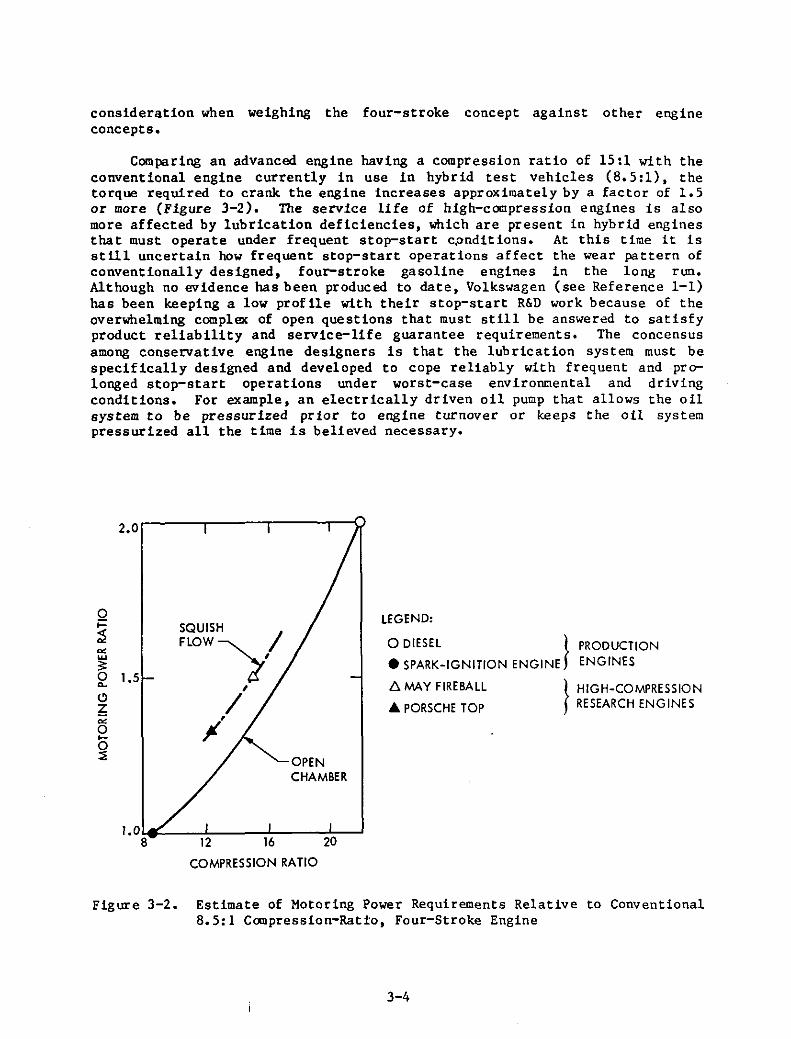
consideration when weighing the four-stroke concept against other engineconcepts.
Comparing an advanced engine having a compression ratio of 15:1 with theconventional engine currently in use in hybrid test vehicles (8.5 :1), thetorque required to crank the engine increases approximately by a factor of 1.5or more (Figure 3-2). The service life of high-compression engines is alsomore affected by lubrication deficiencies, which are present in hybrid enginesthat must operate under frequent stop-start cpnditions. At this time it isstill uncertain how frequent stop-start operations affect the wear pattern ofconventionally designed, four-stroke gasoline engines in the long run.Although no evidence has been produced to date, Volkswagen (see Reference 1-1)has been keeping a low profile with their stop-start R&D work because of theoverwhelming complex of open questions that must still be answered to satisfyproduct reliability and service-life guarantee requirements. The concensusamong conservative engine designers is that the lub rication system must bespecifically designed and developed to cope reliably with frequent and prolonged stop-start operations under worst-case environmental and drivingconditions. For example, an electrically driven oil pump that allows the oilsystem to be pressurized prior to engine turnover or keeps the oil systempressurized all the time is believed necessary•
PRODUCTIONENGINES
}HIGH-COMPRESSIONRESEARCH ENGINES
LEGEND:
o DIESEL }
• SPARK-IGNITION ENGINE
!'>. MAY FIREBAll
... PORSCHE TOP
OPENCHAMBER
SQUISH /
FlOW~,
,/
~'
o~
.----,---.....--.,....--02.0
""w:;:o 1.50-
Cl~
""o....~
1.0 ~:.---:-l:---.....,J'---~--'8 12 16 20
COMPRESSION RATIO
Figure 3-2. Estimate of Motoring Power Requirements Relative to Conventional8.5:1 Compression-Ratio, Four-Stroke Engine
3-4
The No", emission must also be taken into account. High-compression,four-stroke engines are higher in NOx than low-compression engines and dependmore on efficient catalytic converters to meet eQission requirements. Unfortunately, as discussed earlier and shown in Figure 1-2, the converter rarelyachieves its best possible efficiency under frequent stop-start operatingconditions.
Another factor to consider is that all recent four-stroke engine developments, including rotaries, use a continuous-flow, fuel-injection system likethe Bosch K-Jetronic (or similar) system. As discussed earlier (see Reference1-2), tests with hybrid vehicles using a low-compression, four-stroke engineequipped with a continuous fuel-flow injection system have exhibited undesirably high HC emission transients duririg engine start and CO-emission spikesdur ing engine shutdown. The system' s inherent tendency to overshoot at asudden opening of the throttle produces a fuel-rich mixture. At enginecutoff, the manifold vacuum is broken to affect fuel cutoff by opening of aspecial (VW-introduced) vent valve. But with the engine still turning overfor a fe'" times before it comes to a full stop, the system remains partiallyopen, and small amounts of fuel dribble into the engine until the systempressure has decayed below nozzle-opening pressure. This causes a lean tlixtureand high CO emission during every engine cutoff. The built-in, fuel-enrichmentfeatures that provide for a timed injection of extra fuel to facilitate coldstart are also responsible for the high HC emission during engine start.
These deficiencies can be eliminated but will require special development. Instead of developing a stop-start, transient, emission-proof,continuous-flow, fuel-injection system, it would be more straightforward touse a pulse-flo", system that controls fuel· flo'" directly at the injectionnozzle with a solenoid valve. An example is the Bosch K-Jetronic system.Based on the analytical studies conducted at General Electric (see Reference1) a K-Jetronic-equipped, 1.7-1, four-stroke, spark-ignition production Audiengin·e was chosen for use in experimental hybrid vehicles because it wasavailable and because the developer (Volks",agen) already had some stop-starttest experience with this engine. The aforementioned vent valve that breaksthe manifold vacuum at engine cutoff was added later to stop the fuel flowfaster at engine cutoff.
E. TWO-STROKE, SPARK-IGNITION PISTON ENGINE
For the near future, the advanced cylinder, fuel-injected, two-stroke,spark-injection piston engine seems to be the most attractive engine conceptfor use in smaLl automobiles and hybrid vehicles. It has fewer moving parts,is mechanically simple, is most tolerant to poor fuel quality, and rankshighest among all other concepts in service needs and reliability. Its fuelefficiency (see Figures 2-7, 2-8, and 3-la) is competitive with highcanpression, four-stroke, spark-ignition engines and is considerably betterthan that of current four-stroke engines, including the indirect-injectiondiesel engine.
The relatively large amount of residual gases still present at the startof each new cycle represents a built-in EGR that keeps NOx emissions low (see
3-5
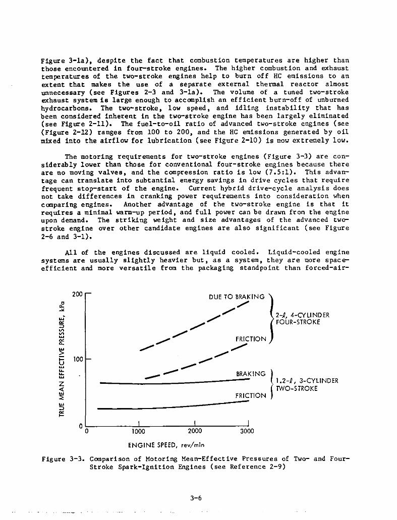
Figure 3-la), despite the fact that cocrbustion temperatures are higher thanthose encountered in four-stroke engines. The higher combustion and exhausttemperatures of the two-stroke engines help to burn off HC emissions to anextent that makes the use of a separate external thermal reactor almostunnecessary (see Figures 2-3 and 3-la). The volume of a tuned two-strokeexhaust system is large enough to accomplish an efficient burn-off of unburnedhydrocarbons. The two-stroke, low speed, and idling instability that hasbeen considered inherent in the two-stroke engine has been largely eliminated(see Figure 2-11). The fuel-to-oil ratio of advanced two-stroke engines (see(Figure 2-12) ranges from 100 to 200, and the HC emissions generated by oilmixed into the airflow for lubrication (see Figure 2-10) is now extremely low.
The motoring requirements for two-stroke engines (Figure 3-3) are considerably lower than those for conventional four-stroke engines because thereare no moving valves, and the compression ratio is low (7.5:1). This advantage can translate into subtantial energy savings in drive cycles that requirefrequent stop-start of the engine. Current hybrid drive-cycle analysis doesnot take differences in cranking power requirements into consideration whencomparing engines. Another advantage of the two-stroke engine is that itrequires a minimal warm-up period, and full power can be drawn from the engineupon demand. The striking weight and size advantages of the advanced twostroke engine over other candidate engines are al so significant (see Figure2-6 and 3-1).
All of the engines discussed are liquid cooled. Liquid-cooled enginesystems are usually slightly heavier but, as a system, they are more spaceefficient and more versatile from the packaging standpoint than forced-air-
2-1, 4-CYLINDERFOUR-STROKE
300020001000
DUE TO BRAKING
.........
~/////~ FRICTION
"..,...................---- BRAKING I____...:-::..- --- 1.2-~, 3-CYLINDER
TWO-STROKEFRICTION
-------
200
~"'"w·
'"=:l
'"'"w'"c..w>.... 100uwu..u..w
Z<I:~w=:l
'"....00
ENGINE SPEED, rev/min
Figure 3-3. Comparison of Motoring Mean-Effective Pressures of Two- and FourStroke Spark-Ignition Engines (see Reference 2-9)
3-6
cooled engine systems. Liquid-cooled engines are also more (=10%) fuelefficient than air-cooled engines. Forced-air cooling, however, seems to bethe better choice from the reliability and cost standpoint, particularlyin case of an auxiliary heat engine for a primary electric car.
F. FOUR-STROKE, SPARK-IGNITION ROTARY ENGINE
Despite the fact that the fuel economy of the advanced rotary engine isnot competitive with advanced two- and four-stroke engines, the rotary engineconcept is still an attractive option for hybrid application because of itsspeed, weight, and size advantages (see Table 2-1, and Figures 3-1 and 3-4).However, if a single-rotor configuration must be chosen to meet hybrid-vehiclepower requirements, the packaging and weight advantages of the rotary engineover its competitors are greatly reduced (Figure 3-5) because of largerbearings and balancing weights.
As shown in Figure 3-6, the motoring requirements for rotary engines areconsiderably lower (up to 50%) than those of four-stroke piston engines. Because it is effectively mixture-lubricated in critical wear areas, the fuelinjected rotary engine requires little, if any, warmup before full power canbe demanded. Another positive feature is its inherent potential for smoothness and speed (see Figure 2-1), which offers the possibility of an integralsingle-shaft design with a high-speed alternator. A shorter service lifethan piston engines may be acceptable for hybrid application because theengine works only part of the total time the vehicle is driven. Advancedrotary engines are expected to be more costly than other advanced candidateengines. However, the cost factor may be acceptable in a hybrid vehicle ifthe advantages it has to offer are of overriding importance.
G. FREE-PISTON ENGINE
The integration of a free-piston engine with a linear alternator ispotentially attractive for battery charging in hybrid vehicles because of itscompactness and smooth operation. Because of its capability of producing highcompression ratios with relatively low friction losses, the free-piston concept lends itself favorably to the implementation of diesel as well as sparkignited (Otto-like) combustion with alternative fuels that tolerate highcompression ratios, such as alcohols and ammonia. Squish techniques as appliedto high-compression gasoline crankshaft engines cannot be applied because thepiston stroke and the points of piston reversal are not fixed in a free-pistonengine. The free-piston diesel has a superior start capability because thepiston stroke is not limited, and a high compression ratio can be produced byelectrically exciting the oscillating masses into resonance. The idle flowrate should also be considerably lower than that of crankshaft engines becauseless friction must be overcome for minimum sustained operation at zero load.
Many of the inherent problems of the free-piston,engine of conventional design that limit its potential toshaft engines can be overcome with modern technology.complex fuel-injection and timing requirements needed for
3-7
internal-combustioncompete with crank
For example, theoptimum free-piston
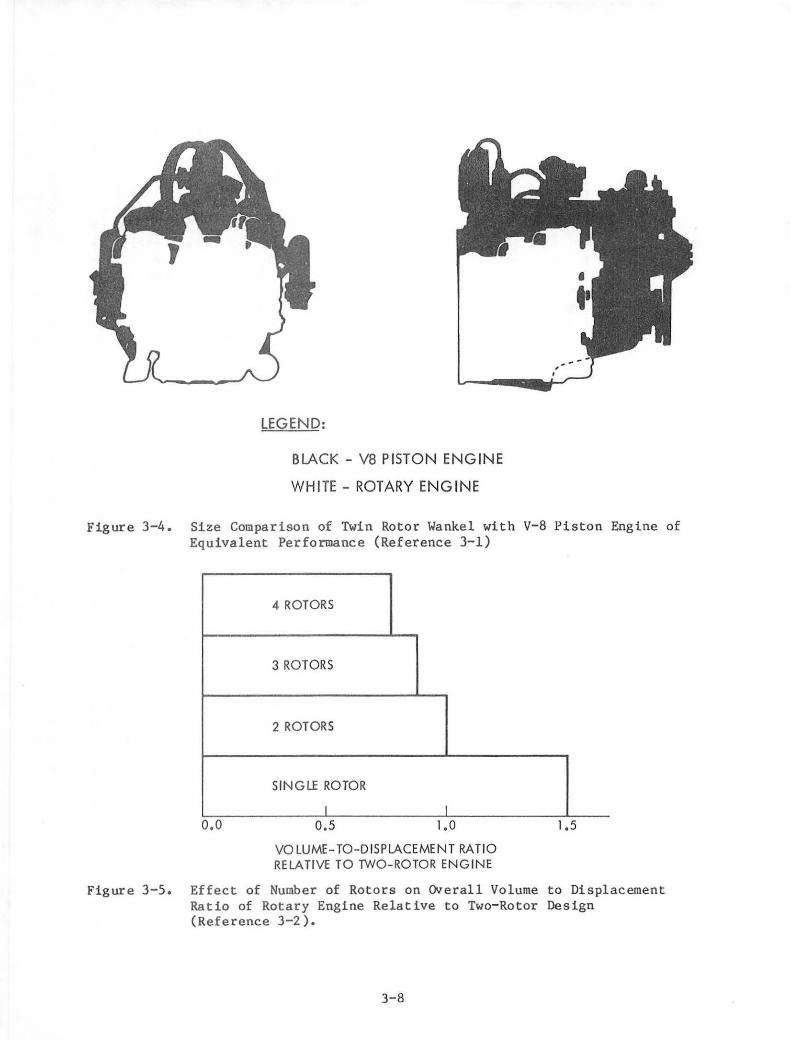
LEGEND:
BLACK - VB PISTON ENGINE
WHITE - ROTARY ENGINE
Figure 3-4. Size Comparison of Twin Rotor Wankel with v-a Piston Engine ofEquivalent Performance (Reference 3-1)
4 ROTORS
3 ROTORS
2 ROTORS
SINGLE ROTOR
I I
0.0 0.5 1.0
VOLUME- TO-DISPLACEMENT RATIORELA TlVE TO TWO-ROTOR ENGINE
1.5
Figure 3-5. Effect of Number of Rotors on Overall Volume to DisplacementRatio of Rotary Engine Relative to Two-Rotor Design(Reference 3-2).
3-8
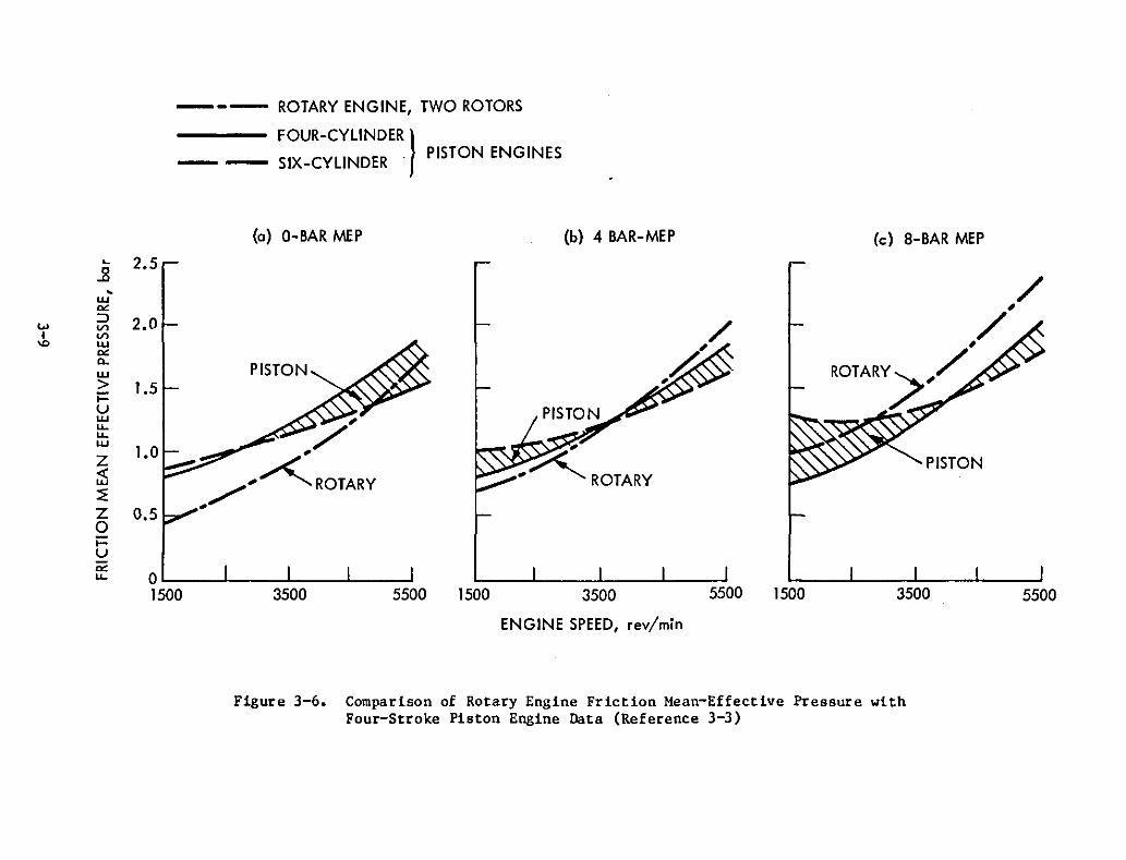
--- ROTARY ENGINE, TWO ROTORS
FOUR-CYLINDER}__ SIX-CYLINDER . PISTON ENGINES
(a) O-BAR MEP (b) 4 BAR-MEP (c) a-BAR MEP~ 2.5
.B•w
"'":> 2.0w VII VI
'" W
"'"Q.
W
> 1.5;::uwu..u..w
1.0 ..Z
"~ROTARY<l:w:EZ 0.50;::u
"'"u.. 01500 3500 5500 1500 3500 5500 1500 3500 5500
ENGINE SPEED, rev/min
Figure 3-6. Comparison of Rotary Engine Friction Mean-Effective Pressure withFour-Stroke Piston Engine Data (Reference 3-3)
operation can be met today with electronic techniques to sense piston speedand reversal points, and to ensure resonance at various load levels by controlling fuel-injection timing, fuel flow, and pressure in the bounce chamber.The application of trip- and miss-control techniques is also possible.
Piston heating, which has been a problem with small, high-speed, freepiston engines, can be overcome with modern high-temperature metallic materials and, perhaps, with ceramics. The free-piston engine lends itself ideallyto the application of ceramic materials and gas lubrication because of itssimple configuration, its relatively low dynamic forces, and the absence oflateral force action on the piston. For battery charging in hybrid passengercars (15-20 kW), a single-mass, turbocompounded, ceramic, free-piston dieselor alcohol-fueled Otto engine with opposing cylinders (Figure 3-7) representsan attractive concept from the fuel efficiency, weight, and packaging standpoint.
As previously mentioned, the free-piston, linear-alternator concept isalso an attractive option for the Stirling engine (see Figure 2-26). It wouldeliminate the external sealing problem with high-pressure hydrogen throughdynamic seals and make the Stirling concept more acceptable for hybrid batterycharging as far as packaging and safety are concerned.
3-10
7.@'10%j
7
:m6 @S S~\"4'1 61'-1
.... 3I 4 FP//M......
LEGEND:
I - BLOWER2 - INLET PLENUM3 - INLET PORTS4 - COMBUSTION SPACE5 - PISTONS6 - FUEL INJECTION NOZZLE
SPARK PLUG (ALCOHOL ENGINE)7 - EXHAUST PORTS8 - EXHAUST PLENUM9 - TURBINE
10 - LINEAR ALTERNATOR, STARTER SOLENOID11 - ALTERNATOR, BLOWER STARTER MOTOR
Figure 3-7. Schematic of TurbocOClpounded Free-Piston Power Unit Concept

SECTION IV
SUMMARY AND CONCLUSION
Based on the information presented and considering the self-imposedrating criteria and restraints for the selection of hybrid-vehicle engines,the study concludes as follows:
(1) Among the advanced engine concepts under consideration, the watercooled cylinder fuel-injected, crankcase-scavenged, two-stroke,spark-ignition piston engine emerges as the best choice for futurehybrid vehicles of the parallel powertrain concept. Because ofits low-compression ratio and large internal turbulence this engineis tolerant of poor quality (low-octane) fuels: The two-strokeinherent lubrication physics prevent long-term wear damage due tostop-start operations. Its specific fuel consumption and the powerrequired to crank the engine are lowest. The number of firingsencountered per unit cranking energy and the chance to fire upduring a given number of turns are highest. In summary, the fuelinjected, two-stroke engine is most cost- and energy-ef ficient,and it satisfies all the other HV needs. A carbureted, air-cooledversion of an advanced two-stroke engine equipped with an up-todate oil-spray lubrication system may satisfy the requirements foran aUXiliary engine for a primarily electrically driven vehicle,depending upon area emission restraints.
(2) The spark-ignition, four-stroke engine of current low-compressiondesign is the best backup choice for a hybrid vehicle of the parallel powertrain concept. However, it should be equipped with afuel-injection system that is positively controlled at the pointof injection to reduce to a minimum transient emissions due todribbling after engine cutoff. It should also be equipped with anelectrical, externally powered oil pump that allows pressurizationof the lubrication system prior to engine start. This shouldeliminate the concern about damages due to long-term wear effectsthat potentially result from frequent stop-start operation.
(3) Rotary four-stroke, spark-ignition engines are not competitive inregard to fuel economy, but their small-volume and high-speedcapability may be a decisive factor where the need for theseproperties exists. The rotary engine's high-speed capabilitypermitting it to run directly coupled with a high-speed alternator,as well as its low starting and motoring power requirements, shouldtranslate into fuel savings that must be taken into account whenthe rotary engine is compared with four-stroke engines in ananalysis of hybrid vehicle performance.
(4) The high-compression, four-stroke, spark-ignition engine is notwell-suited for hybrid operations requiring stop-start capahilitybecause of the inherent problems associated with high-compressionratio engines. These are mainly high starting torque and energy
4-1
losses due to high cranking power requirements, high NOX emissionsin combination with a low catalytic converter efficiency, and anincreased susceptibility to the lubrication deficiencies broughtabout by stop-start operations.
(5) The indirect-injection automotive diesel is not competitive at allfor hybrid vehicle use. The direct-injection diesel could be anal ternative to the spark-ignition, two-stroke engine in applications in which its size and weight do not matter and when it isallowed to idle instead of requiring an engine cutoff. An idlingDr-diesel may have advantages over the two-stroke engine whereprolonged air conditioning and heating times are involved.
(6) A free-piston, direct-injection diesel or a spark-ignition enginefueled with alcohol and coupled directly to a linear alternatorare attractive for future use in battery charging, from the standpoint of packaging, fuel efficiency, low vibration, and noise.
(7) Because of the inherent physical laws governing external combustionengines such as the Brayton, Stirling, and steam engines, they arenot suited for use in hybrid-vehicle, stop-start operations at allwithout special measures that remain to be developed. The largenumber of still-omresolved basic development problems as well asan omcertain funding situation in this area of research precludesthe application of external combustion engines for hybrid useswithin the considered (lO-year) time period.
4-2
SECTION V
RECOMMENDATIONS
This study recommends follow-on analysis and experimentation with candidate engine concepts and components that are necessary to support a finalselection of a heat-engine concept for future hybl:id vehicles. Heat enginesare usually not conceived and developed to meet the specific requirements ofhybrid-vehicle operation. Heat engines must be adapted to meet these requirements. Developers usually cannot provide all the data necessary to evaluatea heat-engine concept in regard to its potential for hybrid use and to assessthe modifications necessal:y. Specific hybrid-related analysis and tests otherthan vehicular tests alone are therefore needed to generate the data basenecessary for hybrid-engine selection and development planning. Listed inorder of priority are the following recommendations resulting from thisstudy.
(1) Conduct a comparative driving cycle analysis with most promisingadvanced engine concepts, including an assessment of the transientenergy losses resulting from the motoring, inertial, and startingcharacteristics of each individual concept known to date. Currenthybrid-vehicle models do not realistically account for transientenergy losses because of high-speed motoring, delayed starts, andclutching during frequent and l:apid stop-start operations.
(2) Conduct evaluation bench tests with the high-speed, fuel-injectionsystems discussed in this report to verify the claims made by theirdevelopers, to understand how they function and to determine how toassess their true potential for hybrid use.
(3) Simulate hybrid typical heat-engine opel:ations on the dynamometer.The capability of determining tl:ansient powel: output, crankingpower input, fuel flow, and emissions must be prOVided. Listed inordel: of priority, the following engine concepts should be tested:
(a) A low-compression, four-stroke, spark-ignition engine (Audi1.7) identical to those installed in the hyb rid vehiclescurrently tested. This is necessal:y to better understand thetransient emission behavior of the vehicles tested and totake measures to l:educe the transient emission of the vehicles using this engine to a pOssible minimum. A test programof this nature that uses hardware and equipment on hand wasproposed in September 1982 (Reference 5-1).
(b) A two- or three-cylinder, two-stroke Marine engine developedin the United States modified to meet the combustion andfuel-injection requirements of the OEC research engine (seeReference. 2-10) discussed in sub sect ion II-A3. The engineshould be equipped initially with a conventional dual plungerBosch-jerk pump, unless suggested otherwise as the resultof the bench tests described in V-(2). Two of the sources
•5-1
contacted (see References 2-7 and 2-11) have offered to conduct a task of this nature at cost with their own researchhardware.
(c) A fuel-injected rotary engine has been recently marketed byMazda that develops 100 kW (130 hpJ. The power of thisengine is more than twice the power output projected forhybrid engines, but data could· be reduced to single-rotorconfiguration after the basic friction and pu",ping lossesof the two-rotor engine have been determined.
(d) A high-compression, spark-ignition, four-stroke engine. A 21 engine with a 13:1 compression ratio may possibly be madeavailable from the discussed sources after their own testswith this engine are completed.
(4) Conduct analysis as described in V-(l). Use the transient datagenerated in tests recommended in V-(3).
(5) Conduct a project design study of an alcohol-fueled spark-ignited,free-piston engine coupled to a linear alternator. Use of thelatest technology and innovative design concepts.
(6) Keep abreast with ongoing developments through literature andpersonal communications. Considerable effort has been made in thecourse of this study to locate and approach competent sources andto encour.age their cooperation. It is important to maintain thesecontacts. The evaluation and demonstration of foreign advancedheat-engine technology represents a unique opportunity to gainexperience and to make contributions to the solution of pacingproblems for the benefit of the DOE Hybrid Vehicle Program aswell as for United States industry in general.
5-2
REFERENCES
1. Near-Term Hybrid Vehicle Program, Final Report, General Electric ReportSRD-79-l34l4, October 8, 1979.
2. Hardy, K. S., et al., Advanced Vehicle Subsystem Technology Assessment,JPL Internal Document D-230, Jet Propulsion Laboratory, Pasadena,Calif., September 1982.
3. Hybrid Vehicle Program, Test Report, Test Bed Mule, General Electric Report SRD-81-o91, November 20, 1981.
4. Hybrid Vehicle Program, Final Report, JPL Publication 9950-912, Jet Propulsion Laboratory, Pasadena, Calif., June 30, 1984.
5. Levin, R., et al., Hybrid Vehicle Assessment, JPL Publication 84-15, JetPropulsion Laboratory, Pasadena, Calif., (in press).
1-1. Personal communication with Volkswagen AG., Wolfsburg, Federal Republicof Germany. April 1981.
1-2. Trummel, M. C" and Burke, A. F., "Development History of theTest Vehicle," IEEE Transactions on Vehicular Technology, Vol.No.1, February 1983.
HybridVT-32 ,
1-3. Hybrid Vehicle Program, Interim Report, General Electric Report SRD-8l012, June 30, 1981.
2-1. Lee, Wenpo and Schaefer, H.T., "Verbrauchsreduzierung am Ottor:1otor durchOptimieren von Brennaumform und Verdichtungsverhaeltnis," MTl Motortechnische Zeitschrift 43 (1982) 7/8.
2-2. May, M. G., Lower Specific Fuel Consumption with High Compression LeanBurn Spark Ignited Four-Stroke Engines, SAE 790386
2-3. Gruden, D.O., and Hahn,R., "T.O.P. - The Thermodynamically OptimizedPorsche Engine," 5th Int'l Automotive Propulsion Systems Symposium,April 14-18, 1980.
2-4. Basshuysen, R. V., and Wilmers, G., An Update of the Development of theNew Audi NSU Rotary Engine Generation, SAE 780418, February 27 to March3, 1978.
2-5. Jones, C., An Update of Applicable Automotive Engine Rotary StratifiedCharge Development, SAE 820347, February 22-26, 1982.
2-6. Jones, C" A Review of Curtiss Wright Rotary Engine Developments withRespect to General Aviation Potential, SAE 790621, April 3-6, 1979.
2-7. Personal Communication with Nippon Clean Air Laboratory, Ishikawa-Ken,Japan, 1982-83.
6-1
2-8. Onishi, Shigero, et al., Active Thermo-Atmosphere CombustionNew Combustion Process for Internal Combustion Engines, SAEFebruary 26 to March 2, 1979.
(ATAC): A79-501,
2-9. Personal Communication with Orbital Engine Co., Balacatta, Australia,Visit and Subject Presentation of OEC at Jet Propulsion Labora tory,Pasadena, Calif., August 1983.
2-10. McKay, M. L., Pneumatic Fuel Metering - A New Approach to AdvancedFuel Control, SAE 820351, February 22-26, 1982.
2-11. Berchtold, M. and Eggard. C., "A New Two-Cycle Spark-ignited Engine,"Coof. Rep. 800419, Vol. 2, Fifth Symposium on Autom. Prop. System,Dearborn, Michigan, April 14, 1980.
2-12. Personal Communication with Prof. H. Berchtold, Eidgenoessische Technische Hochschule, Zuerich, Switzerland, at JPL, February 1983.
2-13. Blair, G. P., and Johnson, M. B., Simplified DesignExpansion Chambers for 2-Cycle Gasoline Engines, SAE12-16, 1970.
Criteria for the700123, January
2-14. Rata, Noriyuki, et al., Modification of 2-Stroke Engine Intake Systemfor Improvement of Fuel Consumption Performance through the YamahaEnergy Induction System (YEIS), SAE 810923, 1981.
2-15. Schneider, H•. W., Conventional Engine Techology - Vol II: Status ofDiesel Engine Technology, JPL Publication 81-65, Jet Propulsion Laboratory, Pasadena, Calif., 1981.
2-16. Personal Communication with Bavarian Motor Works, Munich, FederalRepublic of Germany, visit in April 1982.
2-17. "Garrett/Ford Advanced Gas Turbine Program Sunnnary," Garrett-AiResearchBrochure MS636l.
2-18. Klann, T. L. and Johnsen, R. L., "Automotive Gas Turbine DownsizingStudy", NASA - LeRC Presentation, Contractor Coordination Meeting,Dearborn, Michigan, October 26-29, 19B1.
2-19. Advanced Gas Turbine Powertrain System Development Project, GeneralMotors - Detroit Diesel Allison Progress Report, NASA Contract DEN3168, Dearborn, Michigan, October 26-29, 1983.
2-20. Dowdy, M. W., Automotive Stirling Engine Development Program, MTI Rep.No. 8l-ASE 224 PR17.
2-21. Carter, Jr., J.,W. The Carter System - A New Approach for A SteamPowered Automobile, SAE 750071.
6-2
2-22. Taylor, Charles F., The Internal Combustion Engine, 2nd Edition, Vol.7, p. 481, The MIT Press, Cambridge, Massachusetts, 1966.
2-23. "Der Motor Arbeitet Ohne Mechanik," VDI, Nachrichten Nr. 39/26, p. 4,Sept ember 1980.
2-24. "Stelzer Reworks Free-Piston Engine," Automotive News, p. 4, October12, 1981.
2-25. Internal Report, Resonance Motors, Inc., Irvine, California; communication with W. K. Hardy, JPL, February 5, 1980.·
2-26. Rosenguist, K., Lia, T., and Goldwater, B., The Stirling Engine for theAutomotive Application, SAE 790329, February 26 to March 2, 1979.
3-1. Jones, C., New Rotating Combustion Powerplant Development, SAE 650723,Vol. 74, 1966 (Reprint).
3-2. Jones, C., "The Curtiss Wright Rotating Cocbustion Engines Today," SAETransactions, Vol. 73, Reprint 1965.
3-3. van Basshuysen, R., Stutzenberger, H., and Vogt, R., "Unterschiede imReibungsverhalten zwischen Kreiskolbenmotor und Hubkolbenmotoen vonAudi." ATZ Automobiltechnische Zeitschrift, Vol. 84, 1982.
5-1. Schneider, H. W. to Trummel, M. C., "Simulation and Study of HybridTransient Stop-Start Operations on the Dynamometer," JPL 10M 34VSP-82224. September 28, 1982.
6-3

APPENDIX A
CONTACTS MADE IN CONJUNCTION WITH THE HYBRID JEHICLEHEAT-ENGINE EVALUATION TASK
Prof. Helmuth Hieke1Fachhochschule AngsburgD8900 AugsburgBaumgartner Strasse 16Fed. Republic of Germany
Mr Yasunari HoshinoSr. Research EngineerNissan Motor Co. Ltd.Central Eng. Laboratory1, Natsushima-choYokosuka 237, Japan
Dr. Eberhardt WesnesDr. Wenpo LeeMr. Paulus HeidemeierMr. R. Iller schProf. HeilandVolkswagen A. G.3180 Wolfsburg 1Fed. Republic of Germany
Prof. Stuart A. HoenigThe University of ArizonaTucson, Arizona 85721
Dr. S. H. JoNippon Clean Air LaboratoryCO 205-3 Kitaysane MachiKanizawa-shi Ishikawa-keuJapan 920
Dr. Roy ChoudehoryDept. of Mech. Eng.University of Southern CaliforniaOlin Hall 200University Dr., LA 90007
Mr. Max GrainerRobert Bosch Corp.26877 N.W. HwySuite 220Southfield, MI 48034
Mr. Sadamachi SasakiPresidentFuji Heavy Industries7-2 l-Chome Nishi-ShinjukuShinjuku-ku Tokyo, Japan 160
A-I
Ilo-Werke GmbHPostfach 1620D-2080 PinnebergFed. Republic of Germany
Fa. Fichtel Sachs A.G.Postfach 1140D-8720 SchweinfurtFed. Republic of Germany
Dr. W. Gross, Prog. ManagerRobert Bosch Corp.26877 N.W. Hwy, Suite 220Southfield, MI 48034
Mr. H. Po11ar iOutboard Marine Corp.Seashore Dr.Waukegan, IL
Mr. H. BrookhausMgr. Tech. Devel.·Audi NSU Auto Union AGPostfach 2208070 IngolstadtFed. Republic of Germany
Mr. R. van BasshuysenAudi NSU Auto Union AGPostfach 1144D-7107 NeckarsulmFed. Republic of Germany.
Mr. T.W. Mohr, Dir ResearchOMC Research Center4109 N. 27th St.P.O. Box 663Milwaukee, WI 53201
Dr. T. R. SarichOrbital Engine Compo Pty. Ltd.4 Whipple St.BalaccattaWestern Australia 6021
Fa-Croco Ltd.CH-5043 Holziken-HeliportSwitzerland
Dr. Max BerchtoldSwiss Fed. Institute of TechnologyETH CentrumZuerich 8092, Switzerland
·U. S. GOYERNMtNT PRINTING OFFICE: 1985-544-063/10414
A-2
Mr. C. JohnesDirector of Research Rotary CombustionCurtiss Wright Corp.Passaic St.Woodridge, NJ 07075


J
DOE/CS/54209-15 EVALUATION OF HEAT ENGINES FOR HYBRID VEHICLE APPLICATION DOE
__/ °_-!0o _.
C::jtr_
:_ _. o--4 :_
Recommended